

Page 1
Page 2

DEAR VOLVO OWNER
THANK YOU FOR CHOOSING VOLVO
We hope you will enjoy many years of driving pleasure in your
Volvo. The car has been designed for the safety and comfort
of you and your passengers. Volvo is one of the safest cars in
the world. Your Volvo has also been designed to satisfy all current safety and environmental requirements.
In order to increase your enjoyment of the car, we recommend
that you familiarise yourself with the equipment, instructions
and maintenance information contained in this owner’s
manual.
Page 3
Contents
00 Introduction
Important information .................................. 6
Environment ................................................. 8
01 Safety
Safety in the passenger compartment....... 12
Safety mode............................................... 25
Child safety ................................................ 26
02 Locks and alarm
Remote control key/key............................. 34
Keyless drive.............................................. 40
Locks ......................................................... 42
Alarm* ........................................................ 45
2
Page 4
Contents
03 Your driving environment
Instruments and controls............................ 50
Ignition positions ........................................ 59
Seats .......................................................... 60
Steering wheel............................................ 63
Lighting....................................................... 64
Wipers and washing ................................... 73
Windows, rearview and door mirrors.......... 75
Power sunroof*........................................... 79
Starting the engine ..................................... 81
Gearboxes.................................................. 84
Foot brake .................................................. 87
Parking brake.............................................. 89
04 Comfort and driving pleasure
Menus and messages ................................ 94
Climate control ........................................... 99
Audio system............................................ 109
Trip computer ........................................... 118
Compass*................................................. 119
Stability and traction control system........ 120
Adapting driving characteristics............... 121
Cruise control* ..........................................122
Adaptive cruise control* ........................... 123
Collision warning system with
brake support*.......................................... 127
Parking assistance*.................................. 130
Blind Spot Information System, BLIS* ..... 132
Comfort inside the
passenger compartment .......................... 135
Bluetooth handsfree*................................ 140
Built-in phone*.......................................... 145
05 During your journey
Recommendations during driving ............ 152
Refuelling.................................................. 155
Fuel........................................................... 156
Loading .................................................... 158
Driving with a trailer.................................. 162
Towing ...................................................... 168
3
Page 5
Contents
06 Maintenance and
specifications
Engine compartment ............................... 172
Lamps ...................................................... 177
Wiper blades and washer fluid................. 184
Battery...................................................... 186
Fuses........................................................ 189
Wheels and tyres...................................... 194
Car care.................................................... 210
Type designations .................................... 214
Specifications .......................................... 215
07 Alphabetical index
4
Page 6

5
Page 7
Introduction
Important information
Reading the Owner’s Manual
Introduction
A good way of getting to know your new car
is to read the owner’s manual, ideally before
your first journey. This will give you the opportunity to familiarise yourself with new
functions, to see how best to handle the car
in different situations, and to make the best
use of all the car’s features. Please pay attention to the safety instructions contained in
the manual.
The equipment described in the owner’s
manual is not present in all models. In addition to standard equipment, this manual also
describes options (factory fitted equipment)
and certain accessories (extra equipment).
Volvo cars are adapted for the varying requirements of different markets, as well as
for national or local legal requirements and
regulations.
The specifications, design features and illustrations in this owner’s manual are not binding. We reserve the right to make modifications without prior notice.
© Volvo Car Corporation
Option
Certain functionality and equipment can be
purchased as options when a new car is ordered. The range of options may apply to all
cars or sometimes only to certain variants
and/or certain markets. All types of options
are marked with an asterisk * in the Owner’s
Manual.
Contact your Volvo dealer for more information.
Special texts
WARNING
Texts marked with WARNING advise of risk
of personal injury.
IMPORTANT
Texts marked with IMPORTANT advise of
risk of material damage.
NOTE
Texts marked with NOTE give advice or tips
that facilitate use of features and functions
for example.
Footnote
There is footnote information in the Owner’s
Manual that is located at the bottom of the
page or directly adjacent to a table. This information is an addition to the text that it refers to via a number.
Message texts
There are displays in the car that show text
messages. These text messages are highlighted in the Owner’s Manual by means of
the text being slightly larger and printed in
grey. Example
DIM text.
Procedure lists
Procedures where action must be taken in a
certain sequence are numbered in the Owner’s Manual.
When there is a series of illustrations for
step-by-step instructions each step is
numbered in the same way as the corresponding illustration.
There are numbered and unnumbered
arrows which are used to illustrate a
movement or to point out a component.
If there is no series of illustrations for stepby-step instructions then the different steps
are numbered with normal numbers.
Position lists
Red circles containing a number are used
in overview images where different components are pointed out. The number
recurs in the position list featured in
connection with the illustration that describes the item.
6
Page 8

Introduction
Important information
Step lists
A list of steps is used when there is a numbered sequence in the Owner’s Manual.
Example:
• Coolant
•Engine oil
Recording data
One or more of the computers in your Volvo
are capable of recording detailed information. This information is intended for use in
research to enhance safety and for diagnosing faults in some of the in-car systems. The
data may include details regarding seatbelt
use by the driver and passengers, the functions of various vehicle systems and modules, and status information about the engine, throttle, steering, brakes and other systems. This data can also include details of
the way the car is driven. This type of information can include, without being limited to,
specific details such as vehicle speed, the
use of the brake and accelerator pedals and
steering wheel position. This latter type of
data can be stored for a limited period while
the car is being driven and subsequently during a collision or a near-collision. Volvo Car
Corporation will not disclose the stored information without consent. However, Volvo Car
Corporation may be forced to disclose the information due to national legislation. Volvo
Car Corporation and its authorised workshops may also read and use the information.
Accessories and extra equipment
The incorrect connection and installation of
accessories can negatively affect the car’s
electrical system. Certain accessories only
function when their associated software is installed in the car’s computer system. Always
contact an authorised Volvo workshop before installing accessories which are connected to or affect the electrical system.
7
Page 9

Introduction
Environment
Volvo Cars’ environmental philosophy
Environmental care, safety and quality are
the three core values which influence all operations of the Volvo Car Corporation. We
also believe that our customers share our
consideration for the environment.
Your Volvo complies with strict international
environmental standards and is also manufactured in one of the cleanest and most resource-efficient plants in the world. Volvo
Car Corporation has global certification to
the ISO 14001 environmental standard. This
standard supports the work within the area of
the environment.
EPI (Environmental Product Information) is
supplied for all Volvo models. There you can
see how the car’s lifecycle affects the environment.
Read more at www.volvocars.com/EPI
Fuel consumption
Volvo cars have competitive fuel consumption in each of their respective classes. Lower fuel consumption generally results in lower
emission of the greenhouse gas, carbon dioxide.
It is possible for the driver to influence fuel
consumption. For more information read un-
der the heading, Reducing environmental
impact below.
Efficient emission control
Your Volvo is manufactured following the
concept "Clean inside and out" – a concept
that encompasses a clean interior environment as well as highly efficient emission control. In many cases the exhaust emissions are
well below the applicable standards.
Clean air in the passenger
compartment
A passenger compartment filter prevents
dust and pollen from entering the passenger
compartment via the air intake.
A sophisticated air quality system, IAQS* (Interior Air Quality System) ensures that the incoming air is cleaner than the air in the traffic
outside.
The system consists of an electronic sensor
and a carbon filter. The incoming air is monitored continuously and if there is an increase
in the level of certain unhealthy gases such
as carbon monoxide then the air intake is
closed. Such a situation may arise in heavy
traffic, queues and tunnels for example.
The entry of nitrous oxides, ground-level
ozone and hydrocarbons is prevented by the
carbon filter.
Textile standard
The interior of a Volvo is designed to be
pleasant and comfortable, even for people
with contact allergies and for asthma sufferers. Extreme attention has been given to
choosing environmentally-compatible materials. This means that they also fulfil the requirements in the Öko-Tex 100 standard
major advance towards a healthier passenger compartment environment.
Öko-Tex certification covers seatbelts, carpets, thread and fabrics for example. The
leather in the upholstery undergoes chromium-free tanning with natural plant substances and fulfils the certification requirements.
1
, a
Volvo workshops and the environment
Regular maintenance creates the conditions
for long service life for the car and low fuel
consumption, and this way you contribute to
a cleaner environment. When Volvo’s workshops are entrusted with the repair and
maintenance of the car, it becomes part of
our system. We make clear demands regarding the way in which our workshops are de-
1
More information on www.oekotex.com
8
Page 10
Introduction
Environment
signed in order to prevent spills and discharges into the environment. Our workshop
staff have the knowledge and the tools required to guarantee good environmental
care.
Reducing environmental impact
You can help reduce environmental impact,
for example, by driving economically, by purchasing eco-labelled car care products and
by servicing and maintaining the car according to the instructions in the owner’s manual.
The following hints will help you to care for
the environment:
• Decrease fuel consumption by choosing
ECO tyre pressure, see page 207.
• A roof load and ski box increase air resistance, leading to higher fuel consumption.
Remove them immediately after use.
• Remove unnecessary items from the car.
The greater the load the higher the fuel
consumption.
• If the car is equipped with an engine block
heater use it for a few hours before starting from cold. This reduces fuel consumption and exhaust emissions.
• Drive gently and avoid braking too hard.
• Drive in the highest gear possible. Low
engine speeds result in lower fuel consumption.
• Use engine braking to slow down.
• Avoid idling. Take consideration of local
regulations. Switch off the engine in longer
stationary traffic.
• Always dispose of environmentally hazardous waste, such as batteries and oils,
in an environmentally safe manner. If uncertain about disposal, consult an authorised Volvo workshop for advice.
• Service your car regularly.
• High speed increases consumption considerably due to increased wind resistance. A doubling of speed increases wind
resistance four times.
These hints will help reduce fuel consumption without increasing travel time or lessening the enjoyment of driving. Apart from being kind to your car, you’ll be saving money and the Earth’s resources.
9
Page 11

10
Safety in the passenger compartment..................................................... 12
Safety mode............................................................................................. 25
Child safety .............................................................................................. 26
Page 12
SAFETY
01
Page 13
01 Safety
01
Safety in the passenger compartment
Always use seatbelts
Heavy braking can have serious consequences if the seatbelts are not used. Ensure
that all passengers use their seatbelts.
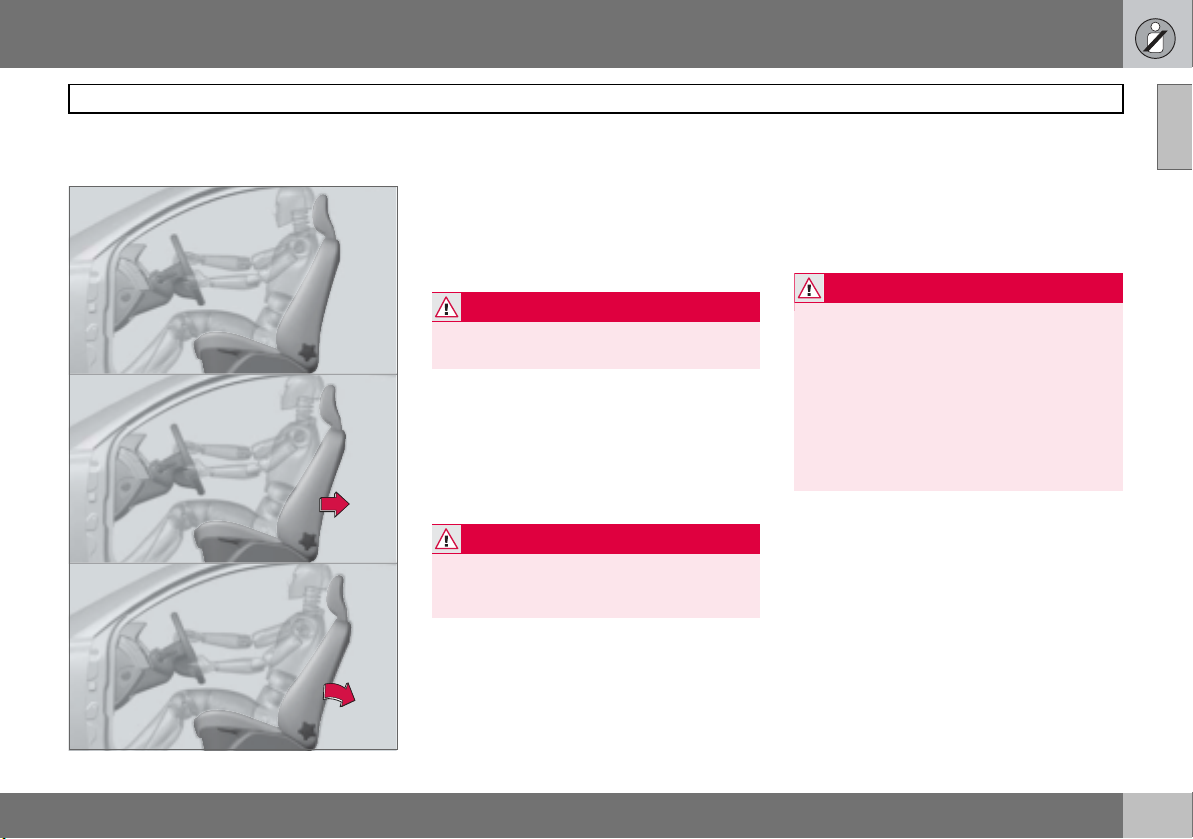
It is important that the seatbelt lies against
the body so it can provide maximum protection. Do not lean the backrest too far back.
The seatbelt is designed to protect in a normal seating position.
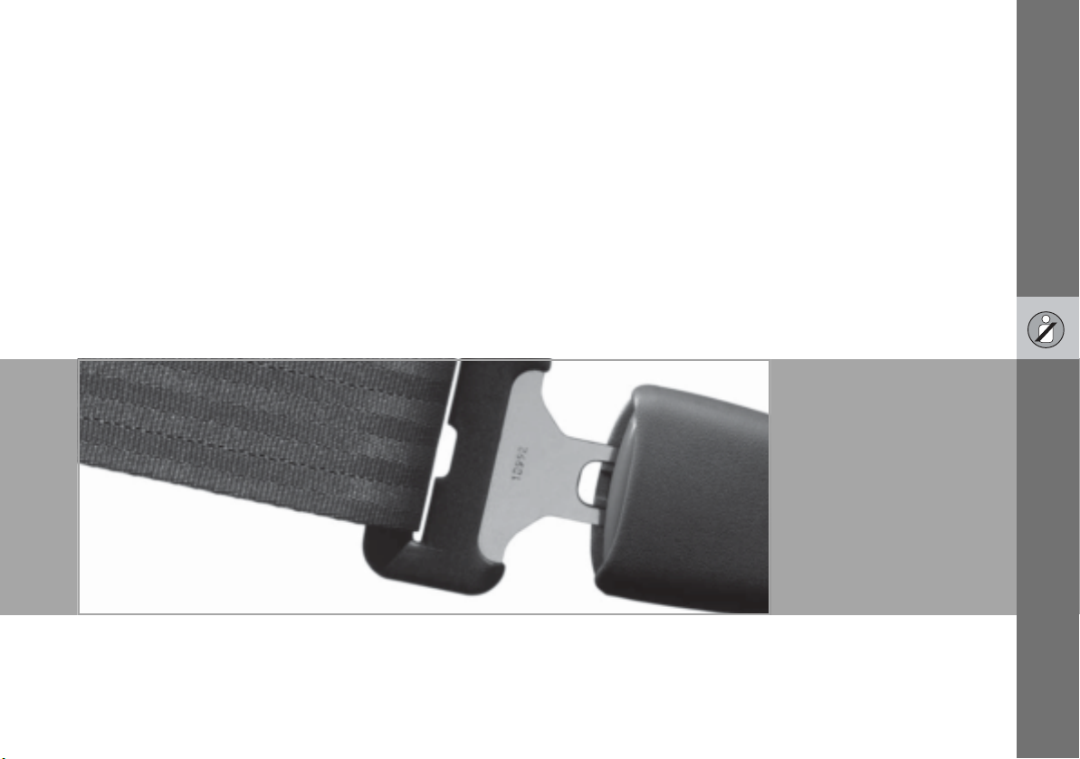
Putting on a seatbelt
Pull the seatbelt out slowly and secure it by
pressing the buckle into the lock. A loud
"click" indicates that the seatbelt has locked.
The buckles only fit the intended lock in the
rear seat
1
1
.
Certain markets
Releasing the seatbelt
Press the red lock button and then let the
seatbelt retract. If the seatbelt does not retract fully, feed the seatbelt in by hand so
that it does not hang loose.
The seatbelt locks and cannot be withdrawn:
• if it is pulled out too quickly.
• during braking and acceleration.
• if the car leans heavily.
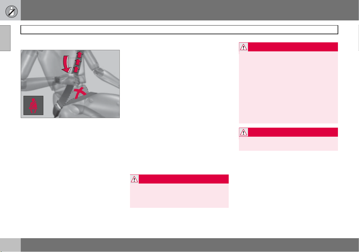
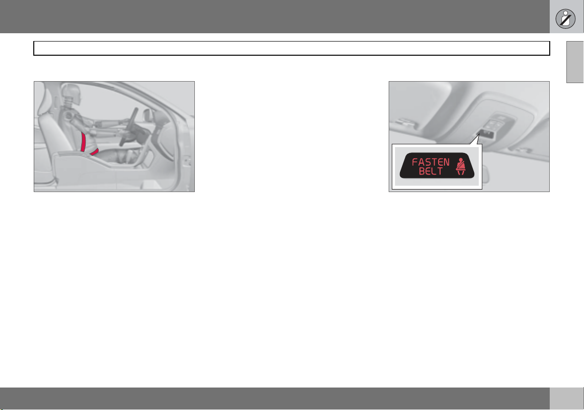
Keep in mind the following:
8803512j
• do not use clips or anything else that can
prevent the seatbelt from fitting properly.
• ensure that the seatbelt is not twisted or
caught on anything.
• the hip strap must be positioned low down
(not over the abdomen).
• tension the hip strap over the lap by
pulling the diagonal shoulder belt as
illustrated.
WARNING
The seatbelts and airbags interact. If a seatbelt is not used or is used incorrectly, this
may diminish the protection provided by the
airbag in the event of a collision.
WARNING
Never modify or repair the seatbelts yourself. Contact an authorised Volvo workshop.
If a seatbelt has been subjected to a major
load, such as in conjunction with a collision,
the entire seatbelt must be replaced. Some
of the protective characteristics of the seatbelt may have been lost, even if it appears
to be undamaged. In addition, replace the
seatbelt if the belt is worn or damaged. The
new seatbelt must be type-approved and
intended for installation in the same position
as the replaced seatbelt.
WARNING
Each seatbelt is designed for only one person.
12
Page 14
01 Safety
Seatbelts and pregnancy
The seatbelt should always be worn during
pregnancy. But it is crucial that it be worn in
the correct way. The diagonal section should
wrap over the shoulder then be routed between the breasts and to the side of the abdomen. The lap section should lay flat over
the thighs and as low as possible under the
abdomen. – It must never be allowed to ride
upward. Remove all slack from the seatbelt
and ensure that it fits close to the body. In
addition, check that there are no twists in the
seatbelt.
As the pregnancy progresses, pregnant drivers should adjust their seats and steering
wheel such that they can easily maintain control of the vehicle as they drive (which means
they must be able to easily operate the foot
pedals and steering wheel). Within this context, they should strive to position the seat
with as large a distance as possible between
the abdomen and the steering wheel.
8704370s
Safety in the passenger compartment
Seatbelt reminder
An audio signal and indicator lamp remind
anyone not wearing a seatbelt to use one.
The audio reminder is speed-dependent. Reminder indicator lamps are located in the roof
console and combined instrument panel. At
low speed, the audio reminder will sound for
the first 6 seconds.
Child seats are not covered by the seatbelt
reminder system.
Rear seat
The seatbelt reminder in the rear seat has
two subfunctions:
• Provides information on which seatbelts
are being used in the rear seat. This is
shown on the information display. The
1
Certain markets
1
01
3905547s
13
Page 15
01 Safety
01
Safety in the passenger compartment
message is automatically cleared after approx. 30 seconds or can be acknowledged manually by pressing the READ
button.
• Provides a warning if one of the rear
seatbelts is unfastened during travel. This
warning takes the form of a message on
the information display along with the
audio/visual signal. The warning ceases
when the seatbelt is re-fastened or can be
acknowledged manually by pressing the
READ button.
The message on the information display
showing which seatbelts are in use is always
available. Press the READ button to see
stored messages.
Certain markets
An audio signal and indicator lamp remind
the driver if not wearing a seatbelt to use one.
At low speed, the audio reminder will sound
for the first 6 seconds.
Seatbelt tensioner
All the seatbelts are equipped with belt tensioners. A mechanism in the belt tensioner
tightens the seatbelt around in the event of a
sufficiently forceful collision. This provides
more effective restraint by the seatbelt for
passengers.
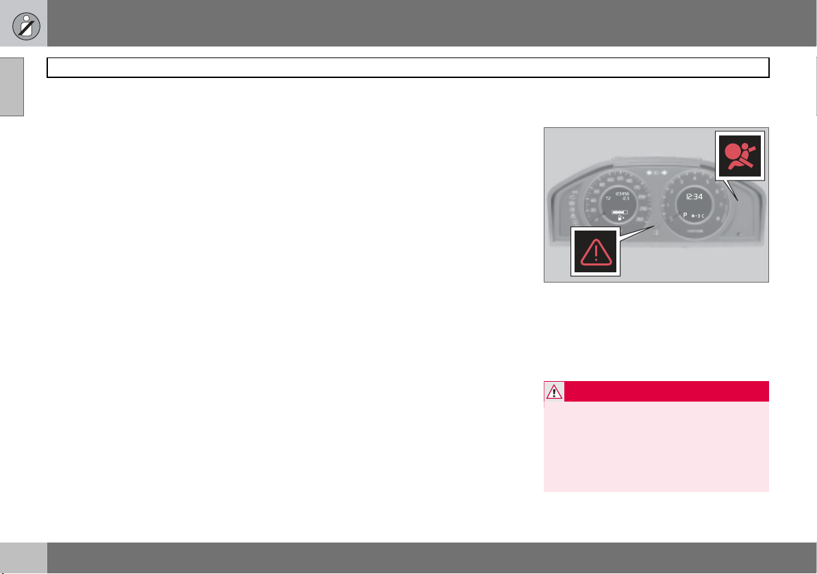
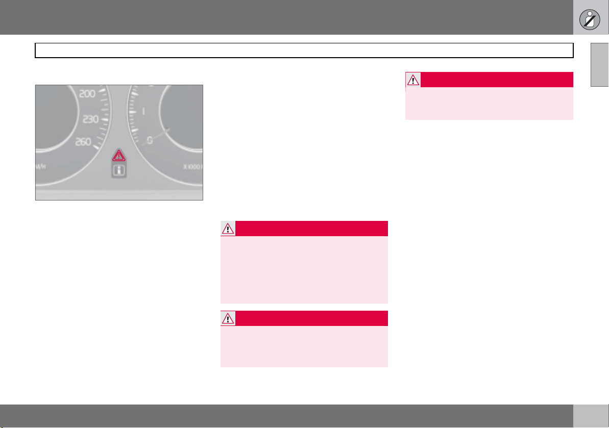
Warning symbol on the combined instrument panel
0
1
o
The airbag system is continually monitored
by the system control module. The warning
symbol on the combined instrument panel illuminates in ignition position II or III. The
symbol goes out after approx. 6 seconds
provided the airbag system is fault-free.
WARNING
If the warning symbol for the airbag system
remains on or illuminates while driving, it
means that the airbag system is not functioning fully. The symbol indicates a fault in
the seatbelt buckle, SIPS, IC system or
other fault in the SRS system. Contact an
authorised Volvo workshop urgently.
3801180s
14
Page 16
01 Safety
As well as the warning symbol, a message
may appear on the information display in
some cases. If the warning symbol malfunctions, the warning triangle illuminates and the
message
SRS Airbag Service urgent appears in the
SRS Airbag Service required or
information display. Contact an authorised
Volvo workshop immediately.
Driver airbag
The car has an SRS airbag (Supplemental
Restraint System) in the steering wheel to
supplement the protection afforded by the
seatbelt. This airbag is fitted into the centre
of the steering wheel. The steering wheel is
marked SRS AIRBAG.
WARNING
The seatbelts and airbags interact. If a seatbelt is not used or is used incorrectly, this
may diminish the protection provided by the
airbag in the event of a collision.
Safety in the passenger compartment
Front passenger airbag
8803515j
The car has an SRS airbag (Supplemental
Restraint System) to supplement the protection afforded by the seatbelt. The passenger
airbag is fitted and stowed above the glovebox. This panel is marked SRS AIRBAG.
WARNING
To minimise the risk of injury if the airbag
deploys, passengers must sit as upright as
possible with their feet on the floor and
backs against the backrest. Seatbelts must
be secured.
WARNING
Do not put objects in front of or above the
dashboard where the passenger airbag is
located.
01
8803516j
15
Page 17
01 Safety
01
Safety in the passenger compartment
WARNING
SRS system
Never place a child in a child seat or on a
booster cushion in the front seat if the airbag (SRS) is activated.
Never allow a child to stand or sit in front of
the front passenger seat. No one shorter
than 140 cm should ever sit in the front passenger seat if the airbag (SRS) is activated.
Failure to follow the advice given above can
endanger the life of the child.
Location, left-hand drive
Location, right-hand drive
8803560s
Left-hand drive
8803561s
Right-hand drive
8803417d
8803418d
The system consists of airbags and sensors.
A sufficiently violent collision trips the sensors and the airbag(s) are inflated with hot
16
Page 18
01 Safety
gas. To cushion the impact, the airbag deflates when compressed. When this occurs,
smoke escapes into the car. This is completely normal. The entire process, including
inflation and deflation of the airbag, occurs
within tenths of a second.
IMPORTANT
Repairs must only be performed by an authorised Volvo workshop. Work on the SRS
system can cause malfunction and result in
serious personal injury.
NOTE
The sensors react differently depending on
the course of the collision and whether or
not the seatbelts on the driver and passenger side are used. It is therefore possible
that only one (or none) of the airbags may
inflate in a collision. The SRS system senses the force of the collision on the car and
adapts accordingly so that one or more airbags are deployed. The capacity of the airbags is also adapted to the collision force to
which the vehicle is subjected.
Safety in the passenger compartment
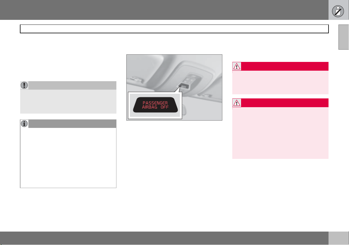
Activating/deactivating the airbag (SRS)*
Indication in roof console
The airbag (SRS) for the front passenger seat
can be deactivated. This is necessary if a
child seat is to be fitted there for example.
A text message on the roof panel indicates
that the passenger airbag (SRS) is deactivated.
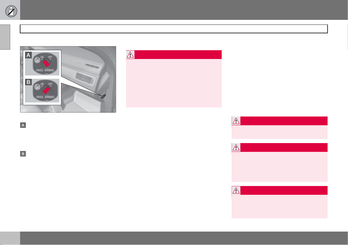
Activating/deactivating
The switch is located on the passenger end
of the dashboard and is accessible when the
passenger door is open. Check that the
switch is in the required position. Volvo recommends that the key blade be used to
change position. For information on the key
blade, see page 37. (Other items with a
shape similar to a key can also be used.) Failure to follow the advice given above can endanger life.
WARNING
If the car is equipped with a front passenger
airbag (SRS), but does not have PACOS
(Passenger Airbag Cut Off Switch), the airbag will always be activated.
WARNING
Activated airbag (passenger seat):
3905550s
Never place a child in a child seat or on a
booster cushion on the front passenger
seat when the airbag is activated. This applies to everyone shorter than 140 cm.
Deactivated airbag (passenger seat): No
one taller than 140 cm should ever sit in the
front passenger seat when the airbag is deactivated.
01
17
Page 19
01 Safety
01
Safety in the passenger compartment
Switch position
PACOS (Passenger Airbag Cut Off Switch)
The airbag (SRS) is activated. With the
switch in this position, persons taller than
140 cm can sit in the front passenger
seat, but never children in a child seat or
on a booster cushion.
The airbag (SRS) is deactivated. With the
switch in this position, children in a child
seat or on a booster cushion can sit in
the front passenger seat, but never persons taller than 140 cm.
WARNING
Do not allow anyone to sit in the front passenger seat if the text message in the roof
panel indicates that the airbag (SRS) is deactivated and if the warning symbol for the
airbag system is also displayed on the combined instrument panel. This indicates that
there has been a severe malfunction. Contact an authorised Volvo workshop immediately.
8803407j
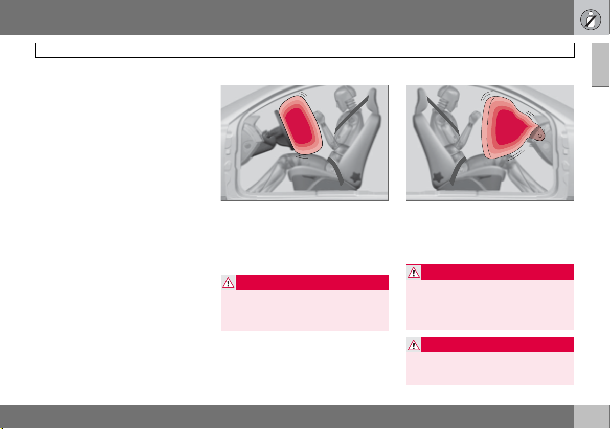
Side airbags SIPS bags
A large proportion of the collision force is
transferred by the SIPS (Side Impact Protection System) to beams, pillars, the floor, the
roof and other structural parts of the body.
The side airbags at the driver’s and front passenger seats protect the chest area and the
hip and are an important part of the SIPS.
The SIPS bag system consists of two main
components, side airbag and sensors. The
side airbags are located in the front seat
backrests.
WARNING
Side airbags are a supplement to the SIPS
system. Always use a seatbelt.
WARNING
Repairs must only be performed by an authorised Volvo workshop.
Work on the SIPS system can cause malfunction and result in serious personal injury.
WARNING
Do not put objects in the area between the
outside of the seat and the door panel,
since this area is required by the side airbag.
18
Page 20
01 Safety
WARNING
Use only seat covers approved by Volvo.
Other seat covers may impede the operation of the side airbags.
Child seats and side airbags
The side airbag does not diminish the protection provided by the car to children seated in
a child seat or on a booster cushion.
A child seat or booster cushion can be
placed on the front passenger seat provided
that the car does not have an activated passenger airbag.
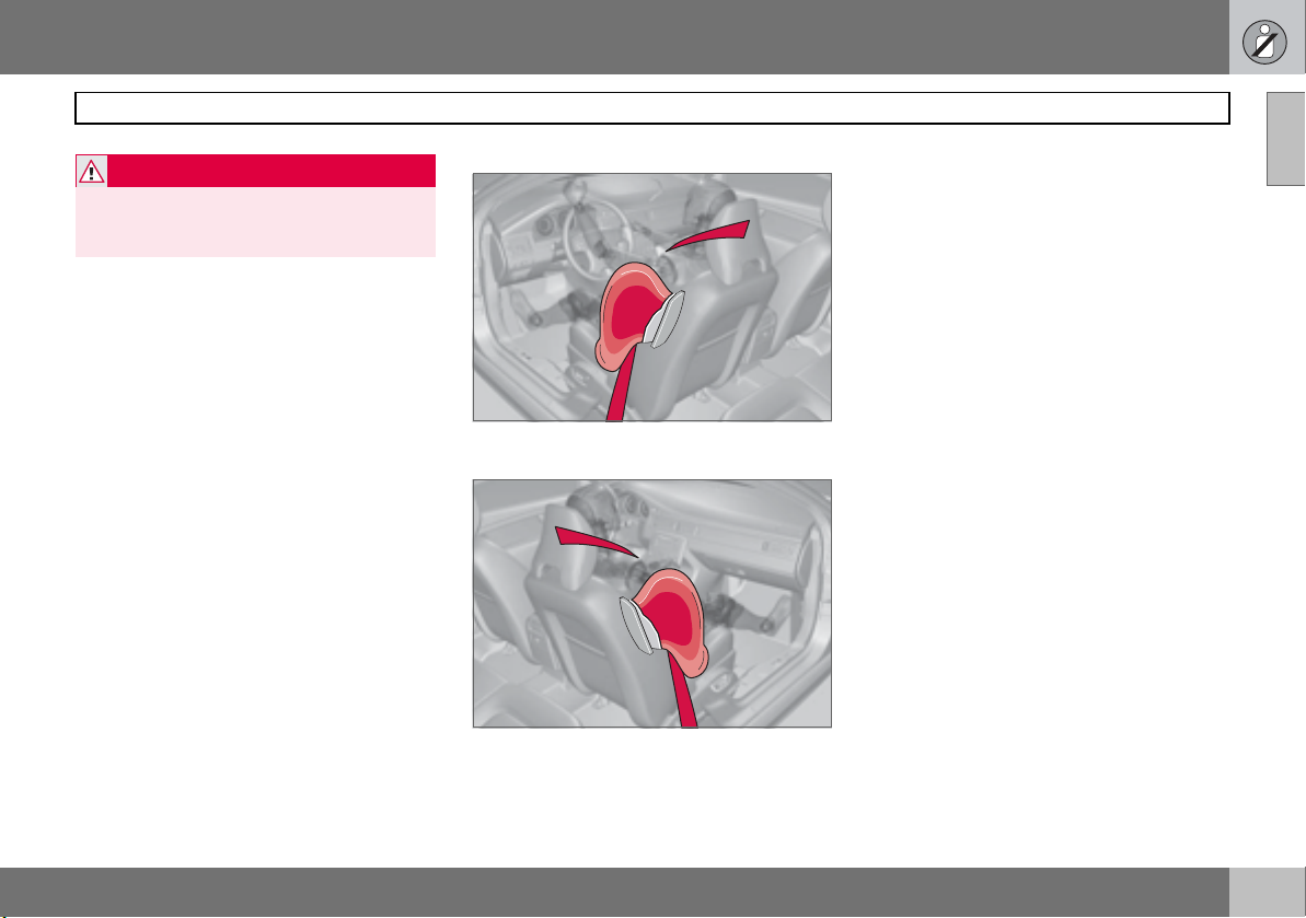
SIPS bag system
Driver’s seat, left-hand drive
Front passenger seat, left-hand drive
Safety in the passenger compartment
The SIPS bag system consists of side airbag
and sensors. A sufficiently violent collision
trips the sensors and the side airbags are inflated. The airbag inflates between the occupant and the door panel and thereby cushions the initial impact while deflating. The
side airbag is only normally deployed on the
side of the collision.
8803566s
8803567s
01
19
Page 21
01 Safety
01
Safety in the passenger compartment
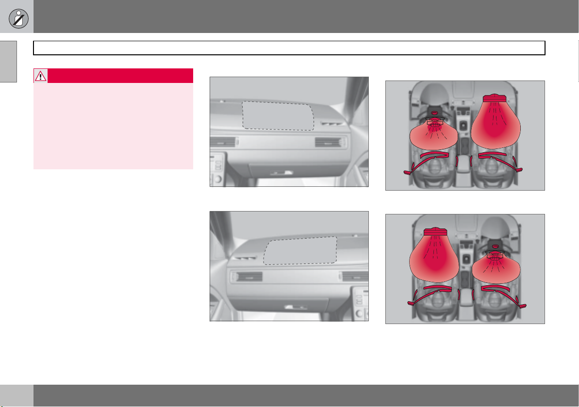
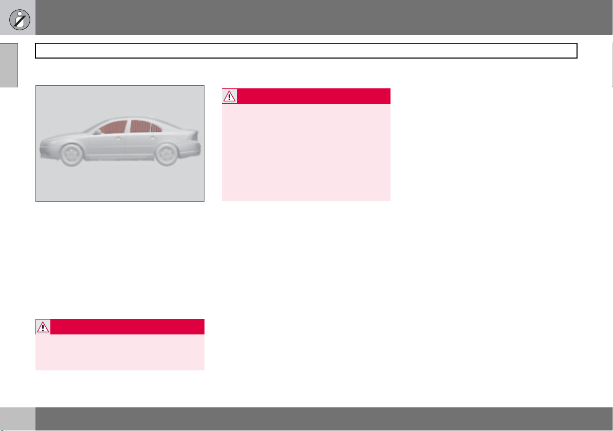
Inflatable Curtain (IC)
The inflatable curtain IC (Inflatable Curtain) is
a supplement to the SIPS and SRS airbags. It
is fitted in the headlining along both sides of
the roof and protects both front and rear seat
passengers. A sufficiently violent collision
trips the sensors and the inflatable curtain is
inflated. The inflatable curtain helps to prevent the driver and front seat passenger from
striking their heads on the inside of the car
during a collision.
WARNING
The inflatable curtain is a supplement to the
seatbelts.
Always use a seatbelt.
WARNING
Never hang or attach heavy items onto the
handles in the roof. The hook is only designed for light clothing (not for solid objects such as umbrellas for example).
Do not screw or install anything onto the
car’s headlining, door pillars or side panels.
This could compromise the intended protection. Only ever use Volvo genuine parts
that are approved for placement in these areas.
8803556s
20
Page 22
01 Safety
Protection against whiplash injury –
WHIPS
The whiplash protection system (WHIPS)
consists of energy absorbing backrests and
specially designed head restraints for the
front seats. The system is actuated by a rearend collision, where the angle and speed of
the collision, and the nature of the colliding
vehicle all have an influence.
WARNING
The WHIPS system is a supplement to the
seatbelts. Always use a seatbelt.
Properties of the seat
When the WHIPS system is deployed, the
front seat backrests are lowered backward to
alter the seating position of the driver and
front seat passenger. This reduces the risk of
whiplash injury.
WARNING
Never modify or repair the seat or WHIPS
system yourself. Contact an authorised
Volvo workshop.
WHIPS system and child seats/booster
cushions
The WHIPS system does not diminish the
protection provided by the car to children
seated in a child seat or on a booster cush-
8803529j
ion.
Safety in the passenger compartment
Correct seating position
For the best possible protection, the driver
and front seat passenger should sit in the
centre of the seat with as little space as possible between the head and the head restraint.
WARNING
If a seat has been subjected to extreme
forces, such as due to a rear-end collision,
the WHIPS system must be checked by an
authorised Volvo workshop.
Part of the WHIPS system’s protective capacity may have been lost even if the seats
appear to be undamaged. Contact an authorised Volvo workshop to have the system checked even after a minor rear-end
collision.
01
21
Page 23
01 Safety
01
Safety in the passenger compartment
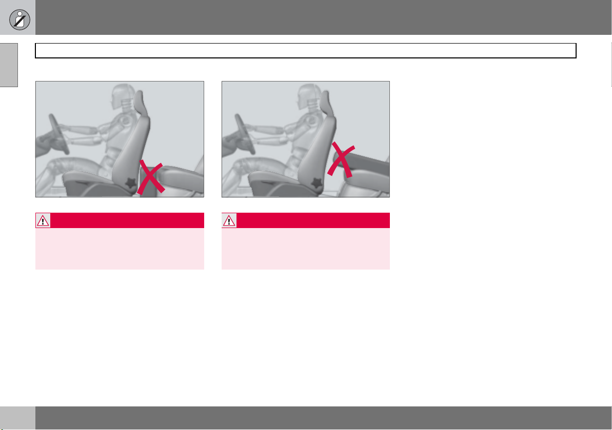
Do not obstruct the WHIPS system
WARNING
Do not squeeze rigid objects between the
rear seat cushion and the front seat backrest. Make sure you do not to obstruct the
function of the WHIPS system.
8803530j
WARNING
If a rear seat backrest is folded down, the
corresponding front seat must be moved
forward so that it does not touch the folded
backrest.
8803531j
22
Page 24
01 Safety
Safety in the passenger compartment
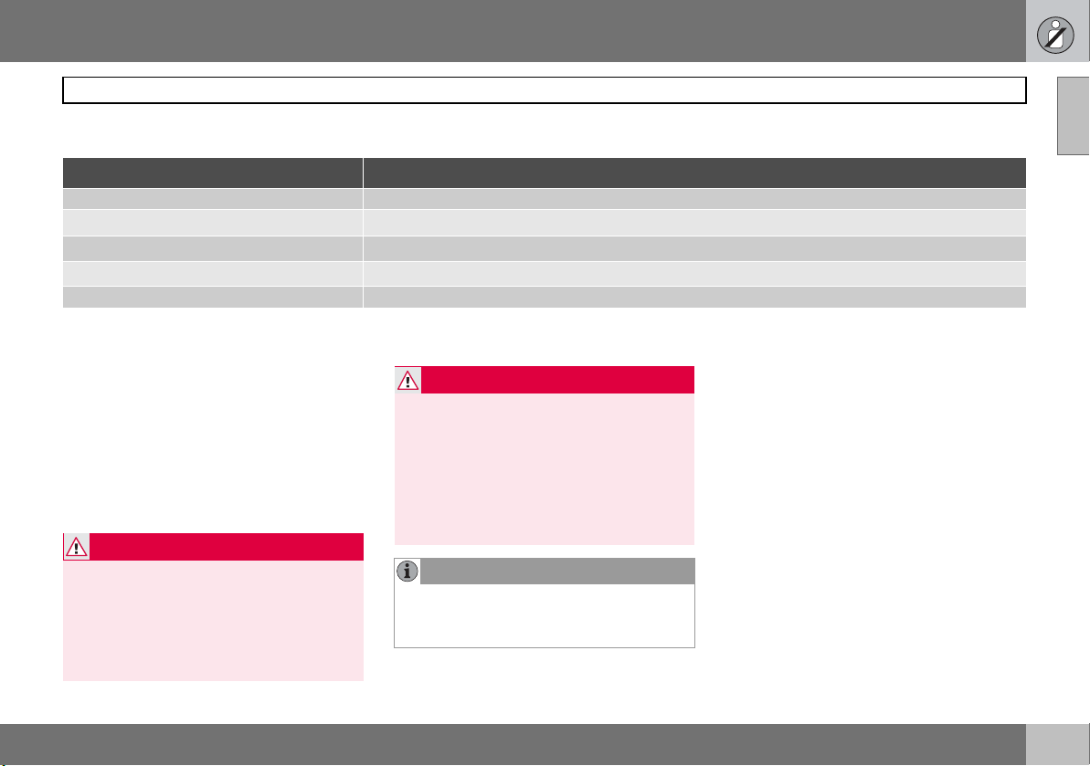
When the systems deploy
System Tr i gg e re d
Seatbelt tensioner In a frontal collision, side-impact accident or a rear-end collision.
Airbags (SRS)
Side airbags (SIPS)
Inflatable Curtain IC
Whiplash protection WHIPS In a rear-end collision.
1
The bodywork of the car could be greatly deformed in a collision even without airbag deployment. A number of factors such as the rigidity and weight of the object
hit, the speed of the car, the angle of the collision etc. affects how the different safety systems of the car are activated.
If the airbags have been deployed, Volvo recommends:
• Have the car transported to an authorised
Volvo workshop.Do not drive with deployed airbags.
• Let an authorised Volvo workshop replace
components in the car’s safety system.
• Always contact a doctor.
WARNING
The airbag control module is located in the
centre console. If the centre console is
drenched with water or other liquid, disconnect the battery cables. Do not attempt to
start the car since the airbags may deploy.
Have the car transported to an authorised
Volvo workshop.
In a frontal collision1.
In a side-impact accident1.
In a side-impact accident and in some cases in a frontal collision1.
WARNING
Never drive with deployed airbags. They
can make steering difficult. Other safety
systems may also be damaged. The smoke
and dust created when the airbags are deployed can cause skin and eye irritation/injury after intensive exposure. In case of
irritation, wash with cold water. The rapid
deployment sequence and airbag fabric
may cause friction and skin burns.
NOTE
The SRS, SIPS, IC and belt tensioner systems are deployed only once during a collision.
01
23
Page 25
01 Safety
01
Safety in the passenger compartment
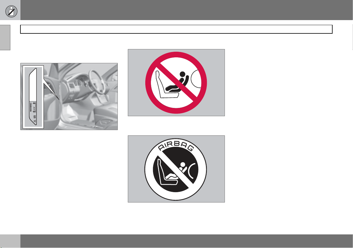
AIRBAG decals
SIPS airbag decal
THIS CAR USE EQUIPPED WITH SIPSBAG IN EACH FRONT SEAT
DO NOT INSTALL ANY ACCESSORIES ON THE SIDE OR NEAR THE SIPSBAG
DO NOT USE EXCESSIVE FORCE ON THE SIDE OF THE SEAT
DO NOT USE ASSESSOY SEAT COVERS UNLESS THEY MEET VOLVO´S SPECIFICATION
USE OF OTHER SEAT COVERS COULD REDUCE THE EFFECT OF THE SYSTEM
FOR FURTHER INFORMATION SEE OWNER´S MANUAL
BAG
The SIPS airbag decal is located on the door
pillar
SRS airbag warning decal
8803559s
SRS airbag warning decal (Australia)
The SRS airbag warning decal is located on
the end face of the dashboard on the passenger side.
8803558s 8803557s
24
Page 26
01 Safety
Safety mode
If the car is involved in a collision, the text
Safety mode - See manual may appear on
the information display. This means that the
car has reduced functionality. Safety mode is
a protective state that is enforced when the
collision may have damaged any of the car’s
vital functions, such as the fuel lines, sensors
for one of the safety systems, or the brake
system.
Attempting to start the car
First, check that no fuel is leaking from the
car. There must be no smell of fuel either.
If everything seems normal and you have
checked for indications of fuel leakage, you
may attempt to start the car.
Firstly, remove the remote control key and
then reinsert it. The car’s electronics will then
try to reset themselves to normal mode. Then
try to start the car. If
shown on the display then the car must not
be driven or towed. Even if the car appears to
be driveable, hidden damage may make the
car impossible to control once moving.
Safety mode is still
Moving the car
If Normal mode is shown after Safety mode
has been reset, the car can be moved care-
3801152s
fully out of a dangerous position. Do not
move the car further than necessary.
WARNING
Never attempt to repair your car or reset the
electronics yourself if the car has been in
safety mode. This could result in personal
injury or the car not functioning as normal.
Always allow an authorised Volvo workshop
to check and restore the car to normal status after
Safety mode has been displayed.
WARNING
Never, under any circumstances, attempt to
restart the car if it smells of fuel when the
Safety mode message is displayed. Leave
the car at once.
Safety mode
WARNING
If the car is in safety mode it must not be
towed. It must be transported to an authorised Volvo workshop.
01
25
Page 27
01 Safety
01
Child safety
General
The position of a child in the car and the
choice of equipment are dictated by the
child’s weight and size, for more information
see page 27.
NOTE
Regulations regarding the placement of
children in cars vary from country to country.
Children of all ages and sizes must always sit
correctly secured in the car. Never allow a
child to sit on the knee of a passenger.
Volvo’s own child safety equipment is designed for your car. Use Volvo genuine
equipment to best ensure that the mounting
points and attachments are correctly positioned and are sufficiently strong.
Child seats
Volvo has child safety products that are designed for and tested by Volvo.
When using other child safety products it is
important to read the installation instructions
included with the product.
Do not attach the straps for the child seat to
the horizontal adjustment bar, springs, rails
or beams under the seat. Sharp edges can
damage the straps.
Allow the back of the child seat to rest
against the dashboard. This applies to cars
without a passenger airbag, or where the airbag is deactivated.
WARNING
Never place the child seat in the front seat if
the car is equipped with an activated front
passenger airbag. If problems arise when
fitting child safety products, contact the
manufacturer for clearer instructions.
Location of child seats
You may place:
• a child seat or booster cushion on the
front passenger seat, provided the passenger airbag is not activated.
• a rear-facing child seat in the rear seat that
uses the back of the front seat as support.
Child seats and activated airbags are not
compatible.
Always place a child in the rear seat if the
passenger airbag is activated. A child in the
front passenger seat may suffer serious injury if the airbag deploys.
WARNING
Persons shorter than 140 cm may only sit in
the front passenger seat if the passenger
airbag is deactivated.
26
Page 28
01 Safety
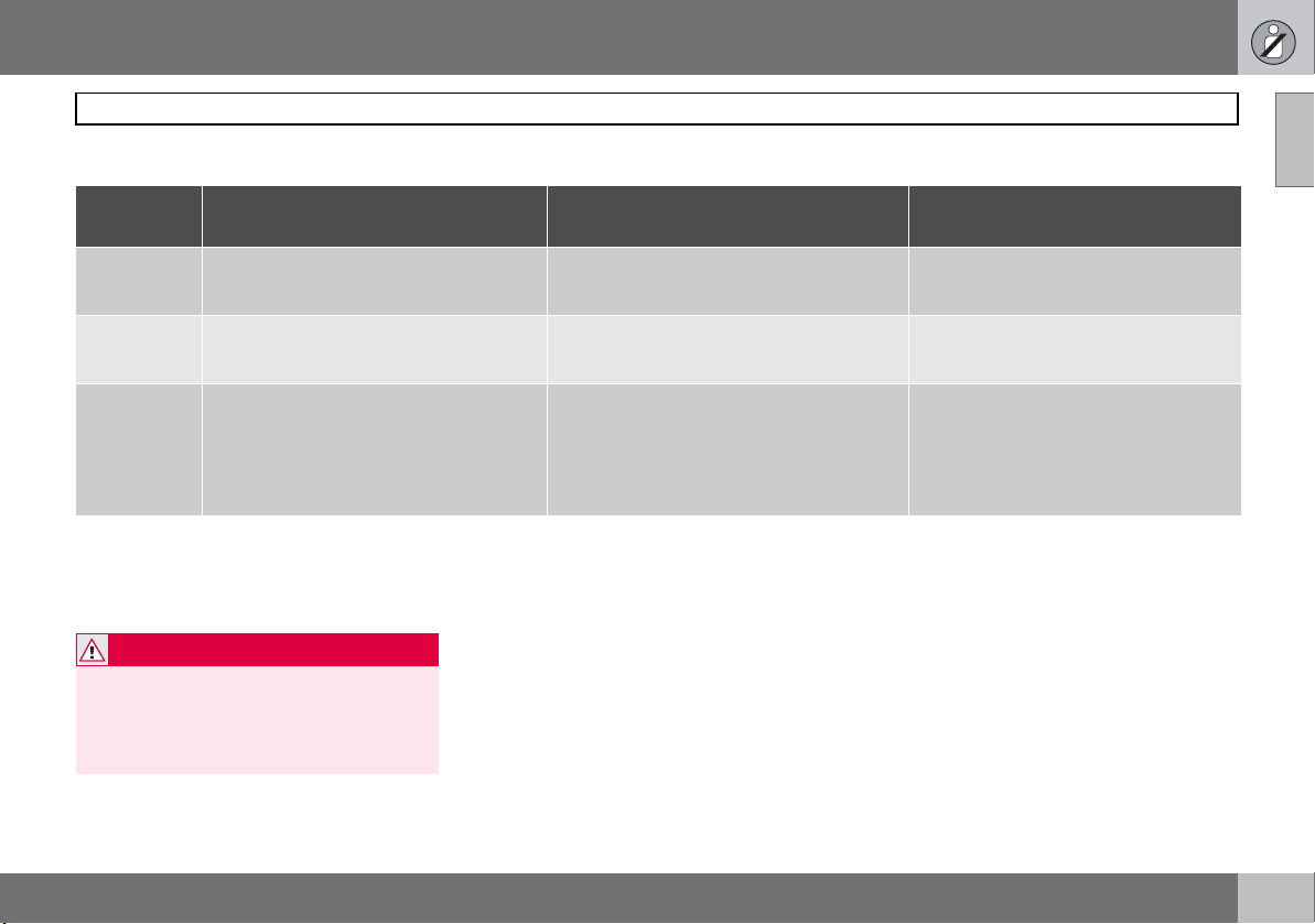
Placement of children in the car
Weight/
Age
<10 kg
(0–9 months)
9–18 kg
(9–36
months)
15–36 kg
(3–12 yr)
1
Suitable for certain child seats as listed in the specified type approval. Child seats can be vehicle-specific, limited, semi-universal or universal.
2
Integrated and approved for this age group.
Front seat Outer rear seat Centre rear seat
Rear-facing child seat, secured with
seatbelt and straps.
1
L
: Type approval no. E5 03135
Rear-facing child seat, secured with
seatbelt and straps.
1
: Type approval no. E5 03135
L
Booster cushion with or without backrest.
1
L
: Type approval no. E5 03139
Rear-facing child seat, secured with
seatbelt, support legs and straps.
1
L
: Type approval no. E5 03135
Rear-facing child seat, secured with
seatbelt, support legs and straps.
1
: Type approval no. E5 03135
L
Booster cushion with or without backrest.
1
L
: Type approval no. E5 03139
Rear-facing child seat, secured with
seatbelt, support legs and straps.
1
L
: Type approval no. E5 03135
Rear-facing child seat, secured with
seatbelt, support legs and straps.
1
: Type approval no. E5 03135
L
Options:
• Booster cushion with or without
backrest.
L1: Type approval no. E5 03139
• Integrated booster cushion.
2
B
: Type approval no. E5 03140
WARNING
Never place the child seat in the front seat if
the car is equipped with an activated front
passenger airbag. If problems arise when
fitting child safety products, contact the
manufacturer for clearer instructions.
Child safety
01
27
Page 29
01 Safety
01
Child safety
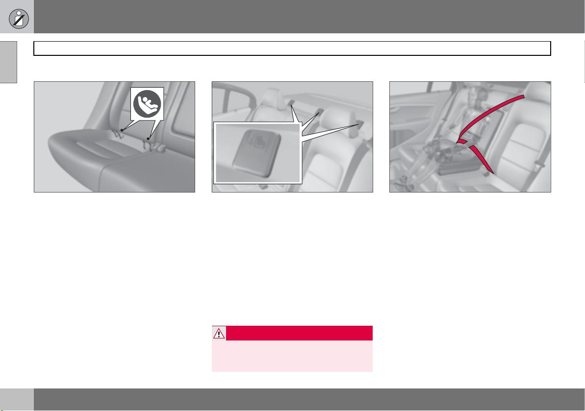
ISOFIX fixture system for child seats*
Mounting points for the ISOFIX fixture system are concealed behind the lower section
of the rear seat backrest, in the outer seats.
The location of the mounting points is indicated by symbols in the backrest upholstery
(see illustration above).
Press the seat cushion down to access the
mounting points.
Always follow the manufacturer’s instructions when connecting a child seat to ISOFIX
mounting points.
Upper mounting points for child seats
8704364s
The car is equipped with upper mounting
points for child seats. These mounting points
are located on the parcel shelf and are concealed by plastic covers. Bend aside the
plastic covers to access each respective
mounting point.
For cars with folding head restraints on the
outside seats the head restraints should be
folded to facilitate installation.
For detailed information on how the child
seat should be tensioned in the upper
mounting points, see the seat manufacturer’s
instructions.
WARNING
The child seat’s belts must always be routed under the rear head restraints before
they are tensioned at the mounting point.
Integrated booster cushion*
8904139s
Volvo’s integrated booster cushion for the
centre rear seat is specially designed to provide optimum safety for children. Combined
with the regular seatbelt, the booster cushion
is approved for children weighing between
15 and 36 kg. Check before driving that:
• the seatbelt is in contact with the child’s
body and is not slack or twisted
• the seatbelt is positioned correctly across
the shoulder
• the lap section of the seatbelt is positioned low over the pelvis to provide optimal protection
• the seatbelt does not lie across the child’s
throat or below the shoulder
• the head restraint is adjusted to suit the
child’s head.
8803565s
28
Page 30
01 Safety
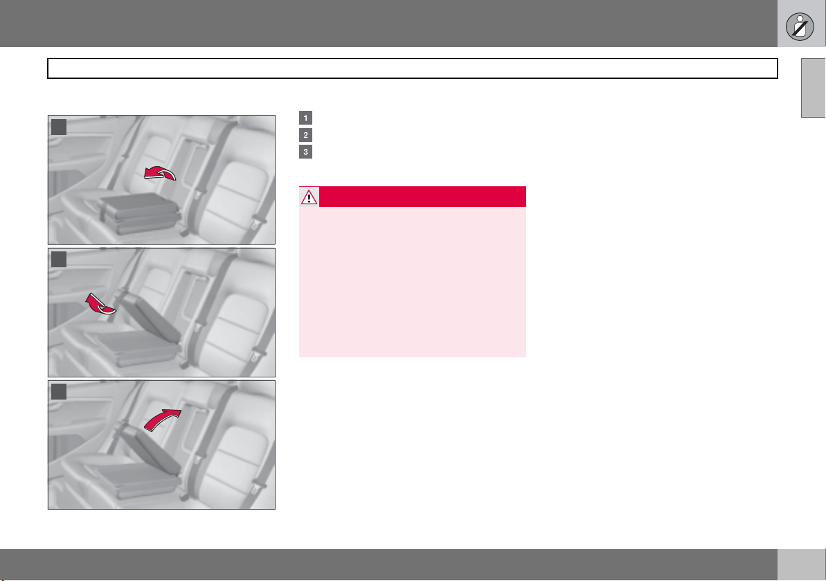
Lowering the booster cushion
1
2
3
Fold down the booster cushion.
Release the Velcro fastener.
Lift back the upper section.
WARNING
Repair or replacement should only be performed by an authorised Volvo workshop.
8505333s
Do not make any modifications or additions
to the booster cushion. If an integrated
booster cushion has been subjected to a
major load, such as in conjunction with a
collision, the entire booster cushion must
be replaced. Even if the booster cushion
appears to be undamaged, it may not afford
the same level of protection. The booster
cushion must also be replaced if it is heavily
worn.
8505330s
Child safety
01
8505343s
29
Page 31

01 Safety
01
Child safety
Raising the booster cushion
1
2
3
Fold down the upper section.
Secure the Velcro fastener.
Fold the booster cushion into the seat
backrest.
NOTE
Make sure that both sections of the booster
cushion are secured with the Velcro strap
before folding up. Otherwise the upper sec-
8505334s
tion can become trapped in the rear seat
backrest when the booster cushion is folded down again.
8505344s
Child safety locks
Manual locking of the rear doors
8302555s
The child safety locks are located on the trailing edge of the rear doors and are only accessible when the doors are open. Use the
key blade to turn the lock and thus activate
or deactivate the child safety lock.
The doors cannot be opened from inside.
The doors can be opened from inside.
NOTE
Cars with electric child safety locks do not
have manual child locks.
30
8505335s
Page 32

01 Safety
Electrical locking of the rear doors* and
power windows
The child safety locks can be activated in ignition position I or II. When the electric child
safety locks are activated, the rear windows
can only be opened from the driver’s door.
The rear doors cannot be opened from inside.
Press the switch on the driver’s door. A message appears on the information display. The
lamp on the button illuminates when the
locks are activated.
WARNING
Always keep the lock buttons pulled up
when driving. In the event of an accident,
this allows the emergency services to get
into the car quickly. Passengers in the rear
seat cannot open the doors from inside if
the child safety locks are activated.
s
98
7
3
0
63
Child safety
01
31
Page 33

32
Remote control key/key ........................................................................... 34
Keyless drive............................................................................................ 40
Locks........................................................................................................ 42
Alarm*....................................................................................................... 45
Page 34

LOCKS AND ALARM
02
Page 35

02 Locks and alarm
Remote control key/key
General
The car is supplied with two remote control
02
keys or PCCs (Personal Car Communicator).
Up to six keys can be ordered. They are used
to start the car and for locking and unlocking.
The PCC has increased functionality compared with the remote control key. Only the
remote control key is referred to in the remainder of this chapter when describing
functions available in both the PCC and remote control key.
A maximum of six remote control keys can
be programmed and used for one single car.
WARNING
If there are children in the car:
Always remember to switch off the power
supply to locks, power windows and sunroof by removing the remote control key if
the driver leaves the car.
Detachable key blades
A remote control key contains a detachable
metal key blade for mechanical locking/unlocking the driver’s door, boot lid and glovebox (service locking).
For key blade functions, see page 37. For
service locking, see page 38.
The key blades’ unique code is available at
authorised Volvo workshops, which can produce new key blades.
Loss of a remote control key
If you lose a remote control key, take the other remote control keys to an authorised Volvo
workshop. The code of the missing remote
control key must be erased from the system
as a theft prevention measure.
The current number of keys registered to the
car can be checked under
Car key memory Number of keys. For a
description of the menu system, see
page 94.
Car settings
Key memory – door mirrors and driver’s
seat*
The settings are automatically connected to
each respective remote control key, see
page 61 and 77.
The function can be activated/deactivated
under
Car settings Car key memory
Seat & mirror positions. For a description of
the menu system, see page 94.
For cars with Keyless drive function, see
page 41.
Indicator for locking/unlocking
When the car is locked or unlocked using the
remote control key, the direction indicators
confirm that locking/unlocking was correctly
performed:
• locking: one flash
• unlocking: two flashes.
After locking the indication is only given if all
locks are activated once the doors have been
closed.
The function can be activated/deactivated
under
Car settings Light settings
Lock feedback light or Car settings
Light settings Unlock feedback light.
For a description of the menu system, see
page 94.
Immobiliser
Each remote control key has a unique code.
The car can only be started with the correct
remote control key with the correct code.
The following error messages in the information display (on the combined instrument
panel) are related to the electronic
immobiliser:
34
Page 36

02 Locks and alarm
Remote control key/key
Message Specification
Key error
Try again
Car key
Not found
Immobiliser
See manual
For starting the car, see page 81.
Error reading remote
control key during start.
Try to start the car
again.
Applies only to the
Keyless drive
PCC’s
function.
reading the PCC during
starting. Try to start the
car again.
Remote control key
function error during
start. Contact an
authorised Volvo
workshop.
Errors
Low battery in remote control key
The batteries should be replaced if:
• the information symbol illuminates and
Car key Battery low is shown in the
display and/or
• the locks repeatedly do not react to signals from the remote control key within
20 metres.
For changing the battery, see page 39.
Functions – remote control key/PCC
1
3
2
4
5
Remote control key
2
1
3
PCC (Personal Car Communicator)
4
5
Locking
Unlocking
Approach lighting
Boot lid
Panic function
Total airing function (global opening)
One long press (at least 4 seconds) on
button or opens or closes all windows
(also closes the sunroof).
3905616s
WARNING
If the sunroof and windows are closed using
the remote control key, check that no one is
in danger of getting hands caught.
The function can be used to quickly air the
car in hot weather for example.
Function buttons
Locking – Locks the doors and boot lid and
then activates the alarm.
Unlocking – Unlocks the doors and boot lid
and deactivates the alarm.
3603821s
The function can be changed from unlocking
all doors simultaneously, to opening the driver’s door after one press of the button and
opening the remaining doors after a further
press of the button (within 10 seconds). The
02
35
Page 37

02 Locks and alarm
Remote control key/key
function is changed under Car settings
Lock settings Unlocking, doors. For a
02
description of the menu system, see
page 94.
Approach lighting – Used to switch on the
car’s lighting at a distance. For more information, see page 69.
Boot lid – Unlocks the boot lid only (without
opening it). For more information, see
page 43.
Panic function – Used to attract attention in
an emergency. Press and hold the red button
for at least 3 seconds or press it twice within
3 seconds to activate the direction indicators
and the horn. The function can be turned off
with the same button once it has been active
for at least 5 seconds. Otherwise the function
switches off automatically after 2 minutes
and 45 seconds.
Range
The remote control has a range of up to 20 m
from the car.
NOTE
The remote control key functions can be
disrupted by surrounding radio waves,
buildings, topographical conditions etc. The
car can always be locked/unlocked using
the key blade, see page 37.
Unique functions – PCC
2
2
1
2
Information button
Indicator lamps
Using the information button enables access to certain information from the car via
the indicator lamps .
Using the information button
1. Press the information button .
2. All indicator lamps flash for approximately 7 seconds and the light travels
around on the PCC. This indicates that
the information from the car has been
read. If any if the other buttons are
pressed during this time then the reading is interrupted.
NOTE
If none of the indicator lamps illuminates
with repeated use of the information button
and in different locations (as well as after
7 seconds and after the light has travelled
around on the PCC), contact an authorised
Volvo workshop.
The indicator lamps provide the information shown in the following illustration.
3603840s
1
3
Green continuous light: the car is locked.
Yellow continuous light: the car is un-
locked.
Red continuous light: the alarm has been
triggered.
Red light flashing alternately in the two
indicator lamps: indicates, using the HBS
(Heart beat sensor), that someone may
2
4
3603841s
36
Page 38

02 Locks and alarm
Remote control key/key
be in the car. This indication is only
displayed if the alarm was triggered.
Range
The PCC lock functions have a range of up
to 20 m from the car.
The approach lighting, panic function and the
functions controlled by the information button have a range of up to a maximum of
100 m from the car.
NOTE
The information button functions can be
disrupted by surrounding radio waves,
buildings, topographical conditions etc.
Out of PCC range
If the PCC is too far away from the car for the
information to be read then the status the car
was last left in is shown, without the light
travelling around on the PCC.
The PCC that was last used for locking/unlocking will show the correct status.
NOTE
If no indicator lamps illuminate when the information button is used then this can be
because the last communication between
the PCC and the car was disrupted by surrounding radio waves, buildings, topographical conditions etc.
Heart Beat Sensor
The function operates using an HBS
(Heart beat sensor). HBS is a supplement to
the car’s alarm system and can indicate at a
distance whether anybody is in the car. This
indication is only displayed if the alarm was
triggered.
The HBS detects an individual’s heartbeat
that is transmitted to the car’s bodywork. For
this reason the function of the HBS can be
disturbed in an environment subject to noise
and vibration.
Keyless drive
See page 40.
Detachable key blade
Use the remote control key’s detachable key
blade to block access to the glovebox and
cargo area
trol key without key blade can only be used
to open the doors and to drive the car.
This key blade is used for locking the glovebox before leaving the car, such as for servicing or valet parking at a hotel for example
(so-called service locking, see page 38).
Hand over the remote control key and keep
the removable key blade.
1
. This means that the remote con-
Unlocking with the key blade
The key blade can be used if the remote control key functions are disrupted or if the remote control key’s batteries have been discharged.
Unlocking the boot lid, see page 44.
The driver’s door is unlocked (without acti-
vating central locking) using the key blade in
the door handle’s keyhole. However, this
triggers the alarm. Deactivate the alarm by
inserting the remote control key in the ignition switch.
02
1
Applies to certain markets
37
Page 39

02 Locks and alarm
Remote control key/key
Removing the key blade
02
1
2
Slide the spring-loaded catch to the side
while pulling the key blade straight out
backwards .
Inserting the key blade
Carefully refit the key blade in place in the remote control key to avoid damaging it.
1. Hold the remote control key with the slot
pointed up and lower the key blade into its
slot.
2. Lightly press the key blade. You should
hear a "click" when the key blade is
locked in.
Service locking*
3603822s
Active locks for remote control key when service
locking is not activated.
Active locks for remote control key when service
locking is activated.
Service locking: turn the key blade in the
glovebox clockwise 180 degrees. This also
means that the boot lid is blocked against
opening with the remote control key (a message is shown in the information display).
Locking the glovebox, see page 43.
8302565s8302564s
38
Page 40

02 Locks and alarm
Remote control key/key
Replacing the remote control key battery
1
1
2
2
3
Battery type: CR2430, 3 V (one in remote
control key and two in the PCC).
Opening
Slide the spring-loaded catch to the
side while pulling the key blade straight
out backwards .
Insert a screwdriver in the hole behind
the spring-loaded catch and gently prise
the remote control key up.
NOTE
Turn the remote control key over with the
buttons facing up, this is to avoid the batteries falling out when it is opened.
IMPORTANT
Avoid touching the battery and its terminals
3603816s
with your fingers, as this could damage their
functionality.
Battery replacement
3603817s
Closely study how the battery/batteries
are secured on the inside of the cover,
with regard to their (+) and (–) sides.
Remote control key
Carefully prise out the battery. Install a
new one with the (+) side down.
PCC
Carefully prise out the batteries. First
install one new one with the (+ ) side up.
Position the white plastic tab in between
and finally install a second new battery
with the (+) side down.
Assembly
1. Press the remote control key together.
2. Hold the remote control key with the
slot pointed up and lower the key blade
into its slot.
3. Lightly press the key blade. You should
hear a "click" when the key blade is
locked in.
IMPORTANT
Dispose of old batteries in an environmentally responsible manner.
G015518
02
39
Page 41

02 Locks and alarm
Keyless drive
Keyless drive (PCC only)
02
Keyless lock and ignition system
The keyless drive function in the PCC allows
the car to be unlocked, driven and locked
without the need for a key. You simply have
to have the PCC with you. The system makes
it easier and more convenient to open the
car, for example when your hands are full.
The car’s two PCCs incorporate the Keyless
function. Additional PCCs can be ordered.
PCC range
In order to open a door or the boot lid, a PCC
must be no more than approx. 1.5 metres
from the car door handle or boot lid. This
means that the person who wishes to lock or
unlock a door must have the PCC with him or
her. It is not possible to lock or unlock a door
if the PCC is on the other side of the car to
the door.
The red circles in the illustration indicate the
range covered by the system’s antennas.
If all PCCs are removed from the car and if all
doors are closed then a warning message is
shown in the information display and an audio reminder signal sounds at the same time.
The message disappears when a PCC is
brought back to the car.
The warning message and audio reminder
signal disappear when the PCC is brought
back to the car after:
8302561s
• a door has been opened and closed
• the PCC is inserted into the ignition switch
•the READ button has been pressed.
Handling the PCC safely
If a PCC with keyless drive function is left in
the car, it is deactivated temporarily when the
car is locked. This prevents unauthorised entry.
However, if someone breaks into the car,
opens the door and finds the PCC, it can be
reactivated. It is therefore important to handle all PCCs with equal care.
IMPORTANT
Never leave a PCC behind in the car.
Interference to PCC function
Electromagnetic fields and screening can interfere with the keyless drive system. For this
reason, do not place the PCC near mobile
phones or metallic objects.
If interference is experienced nonetheless,
use the PCC and key blade in the normal
way, see page 35.
Unlocking
Open the doors with the door handles or
open the boot lid with its handle.
Unlocking with the key blade
If the keyless drive function in the PCC is not
operating, then the driver’s door can be unlocked with the key blade. In this case central
locking is not activated.
NOTE
Unlocking with the key blade triggers the
alarm. For deactivation, see page 46.
40
Page 42

Key memory – driver’s seat and door
mirrors*
PCC memory function
If several people with PCCs approach the
car, then the settings for the person who
opens the driver’s door are implemented.
The settings are changed in two ways after
the driver’s door has been opened:
• from the driver’s seat position: press the
unlock button on the PCC, see page 35
• press the button for seat settings, see
page 61.
Locking
Lock the doors and boot lid by pushing in the
lock button on one of the door handles on
the outside.
All doors and the boot lid must be closed before the car can be locked. Otherwise the car
will not be locked.
Lock settings
The keyless function can be adapted to
specify which of the car doors are to be unlocked, under
settings
of the menu system, see page 94.
Car settings Lock
Keyless entry. For a description
02 Locks and alarm
Keyless drive
02
41
Page 43

02 Locks and alarm
Locks
Locking and unlocking
02
From the outside
The remote control key locks/unlocks all
doors and the boot lid simultaneously. The
lock buttons and inside handles of the doors
are disengaged during locking
The fuel filler flap can be opened when the
car is unlocked. It cannot be opened if the
car is locked and the alarm is armed.
NOTE
The car can be locked even if a door is
1
open
. It is also locked when the door is
closed, and there is a risk that the remote
control key will be locked in.
1
Only applies to cars in certain markets, but not
to cars with Keyless drive.
WARNING
Be aware that there is a risk that you can be
locked in the car if it is locked from the outside.
1
Applies to certain markets
From the inside
Automatic relocking
If none of the doors or the boot lid is opened
within two minutes of unlocking, all are
locked again automatically. This function
prevents the car from being left unlocked unintentionally. For cars with alarms, see
1
.
page 45.
Automatic locking
The doors and boot lid can be locked automatically when the car starts to move.
8302562s
This function can be activated/deactivated
under
All of the doors and the boot lid can be
locked or unlocked simultaneously using the
door buttons on the door panel.
Car settings Lock settings Au-
tolock, doors
. For a description of the menu
system, see page 94.
Unlocking
Press the door unlock button. Press and hold
to also open all windows.
Locking
Press the door lock button after the front
doors are closed. Press and hold to also
close all of the windows and the sunroof if fitted.
All the doors can be locked manually with
their respective lock buttons after they have
been closed. Pull the door handle once to
unlock the door. Pull the door handle twice to
open the door.
42
Page 44

02 Locks and alarm
Locks
Glovebox
A B
Unlock the glovebox by turning the key a
quarter of a turn (90 degrees) anticlockwise. The keyhole is vertical in the unlocked position.
Lock the glovebox by turning the key a
quarter of a turn (90 degrees) clockwise.
The keyhole is horizontal in the locked
position.
The glovebox can only be locked and unlocked with the removable key blade in the
remote control key.
Service locking, see page 38.
Unlocking/locking the boot lid
8302560s
Unlocking with the remote control key
Press the remote control key button to unlock the boot lid.
NOTE
The function does not open the boot lid.
The alarm indicator on the instrument panel
goes out to show that the whole car is not
armed. The alarm’s level and movement sensors and the sensors for opening the boot lid
are automatically disconnected. The doors
remain locked and armed.
Locking with the remote control key
Press the remote control key button for locking, see page 35.
The alarm indicator on the instrument panel
starts to flash, which shows that the alarm is
armed.
If the doors are locked when the boot lid is
closed then it remains unlocked until the car
is locked with the remote control.
Unlocking the car from inside
3905612s
1
Press the headlamp control panel button
to unlock the boot lid.
02
3603845s
43
Page 45

02 Locks and alarm
Locks
Unlocking with the key blade
02
1
2
If the remote control key button for opening
the boot lid is not working then the boot lid
can be unlocked with the key blade.
Prise off the plug covering the keyhole.
Unlock the boot lid by turning the key
blade one half turn anticlockwise as
illustrated.
Deadlocks
8302568s
1
When deadlocked, the doors cannot be
opened from the inside if they are locked.
The deadlocks are activated with the remote
control key and are set after a 10 second delay after the doors are locked.
The car can only be unlocked from a dead-
8302569s
lock state with the remote control key. The
driver’s door can also be unlocked from the
outside with the key.
Temporary deactivation of deadlocks
If someone wants to stay in the car and the
doors still need to be locked from the outside, then the deadlocks can be deactivated.
1. Remove the remote control key from the
ignition switch. Deactivation is only possi-
1
Applies to certain markets
ble within one minute after the engine has
stopped.
2. Press the button.
If the car is equipped with an alarm, the
movement and tilt detectors* are also deactivated at the same time, see page 47.
The light in the button remains on until the
car is locked with the remote control key. A
message remains on the display for
10 seconds or until the car is locked. The detectors and deadlocks are reactivated the
3905611s
next time the car is started.
WARNING
Do not allow anyone to remain in the car
without first deactivating the deadlocks to
avoid the risk of anyone being locked in.
44
Page 46

02 Locks and alarm
Alarm*
General
The alarm is triggered if:
• a door, the bonnet or the boot lid is
opened
• a non-approved key is used in the keyhole
or if force is exerted on the keyhole.
• a movement is detected in the passenger
compartment (if fitted with a movement
detector)
• the car is raised or towed away (if fitted
with a tilt detector*)
• a battery cable is disconnected.
• anyone tries to disconnect the siren.
If there is a fault in the alarm system, a message appears on the information display.
Contact an authorised Volvo workshop.
NOTE
The movement detectors trigger the alarm
in the event of movements in the passenger
compartment. For this reason the alarm
could be triggered is the car is left with a
window open or if an electric passenger
compartment heater is used. To avoid this:
close the windows when leaving the car and
aim the air from the passenger compartment heater so that it is not directed up into
the passenger compartment.
NOTE
Do not attempt to repair or modify alarm
system components. All such attempts
could affect the terms of insurance.
Alarm indicator
An alarm indicator on the dashboard indicates the alarm system’s status:
• lamp off – the alarm is disarmed
• the lamp flashes once a second – the
alarm is armed
• the lamp flashes rapidly after disarming
the alarm (and until the remote control key
is inserted in the ignition switch and ignition position I is reached) – the alarm has
been triggered.
Arming the alarm
Press the remote control key lock button. A
long flash from the car’s direction indicators
confirms that the alarm is armed and that the
doors are locked.
The way in which the car confirms that the
alarm is armed can be adapted to your requirements under
settings
of the menu system, see page 94.
8302563s
Car settings Lock
Keyless entry. For a description
02
45
Page 47

02 Locks and alarm
Alarm*
Disarming the alarm
Press the remote control key unlock button.
02
Two short flashes from the car’s direction indicators confirm that the alarm is disarmed
and that the doors are unlocked.
Deactivating a triggered alarm
Press the remote control key unlock button
or insert the remote control key in the ignition
switch. Confirmation is given by two short
flashes from the direction indicators.
Other alarm functions
Automatic arming of the alarm
This function prevents the car being left with
alarm disarmed unintentionally.
If the car is unlocked with the remote control
key (and the alarm is disarmed) and none of
the doors or the boot lid is opened within two
minutes then the alarm is automatically
armed. The car is locked at the same time.
Alarm signals
When the alarm is triggered, the following
happens:
• A siren sounds for less than 30 seconds.
The siren has its own battery which is
independent of the car battery.
• The direction indicators flash for five minutes or until the alarm has been deactivated.
Remote control key not working
If the remote control key is not working, the
alarm can still be switched off and the car
started as follows:
1. Open the driver’s door with the key blade.
The alarm is triggered and the siren
sounds.
2. Insert the remote control key in the
keyhole. The alarm is deactivated. The
alarm indicator flashes quickly until the
remote control key is inserted.
46
Page 48

02 Locks and alarm
Alarm*
Temporary disarming of the alarm
Deactivation of the detectors
To prevent the alarm being triggered erroneously, such as during a ferry journey, the
movement and tilt detectors can be temporarily disengaged.
Press the button for disengagement. Disengagement is only possible within one minute
after the engine has stopped. The light in the
button remains on until the car is locked.
A message remains on the display for
10 seconds or until the car is locked.
The detectors are reactivated the next time
the car is started.
If the car is equipped with deadlocks then
this is engaged at the same time, see
page 44.
Testing the alarm system
Testing the movement detector in the
passenger compartment
1. Close all windows. Remain in the car.
2. Arm the alarm, see page 45.
3. Wait 15 seconds.
4. Trigger the alarm by moving your arms
forward and back at backrest height. A
siren sounds and all direction indicators
flash.
5. Deactivate the alarm by unlocking the
car with the remote control key.
3905611s
Testing the alarm sensors in the doors
1. Arm the alarm, see page 45.
2. Wait 15 seconds.
3. Unlock the driver’s door using the key
blade.
4. Open the driver’s door. A siren sounds
and all direction indicators flash.
5. Deactivate the alarm by unlocking the
car with the remote control key.
Testing the alarm sensors in the bonnet
1. Sit in the car and deactivate the alarm, see
page 46.
2. Arm the alarm, see page 45. Remain in
the car and lock the doors with the
button on the remote control key.
3. Wait 15 seconds.
4. Open the bonnet with the handle under
the dashboard. A siren sounds and all
direction indicators flash.
5. Deactivate the alarm by unlocking the
car with the remote control key.
02
47
Page 49

48
Instruments and controls ......................................................................... 50
Ignition positions...................................................................................... 59
Seats ........................................................................................................ 60
Steering wheel ......................................................................................... 63
Lighting .................................................................................................... 64
Wipers and washing................................................................................. 73
Windows, rearview and door mirrors ....................................................... 75
Power sunroof*......................................................................................... 79
Starting the engine................................................................................... 81
Gearboxes................................................................................................ 84
Foot brake................................................................................................ 87
Parking brake ........................................................................................... 89
Page 50

YOUR DRIVING ENVIRONMENT
03
Page 51

03 Your driving environment
Instruments and controls
Instrument overview
03
20
9
10
19
Left-hand drive
1 2 3
18 17 16
4 5 6 7 8
15
11
12
13
14
9
10
8505311s
50
Page 52

03 Your driving environment
Instruments and controls
Function Page Function Page
Menus and messages, direction indicators, main/
dipped beam, trip computer
Cruise control 122, 58 Climate control, ECC 102
Horn, airbags 63, 15 Gear selector 84
Combined instrument panel 54, 58 Controls for active chassis (Four-C) 121
Menu, audio and phone control 94, 109,
Ignition switch 81 Steering wheel adjustment 63
Start/stop button 59 Parking brake 89, 89
Hazard warning flashers 67 Bonnet opener 172
Door handle – Seat adjustment 60
Control panel 75, 77, 31,
97, 67, 65,
118
140
42
Menu control, climate control and audio system 94, 102,
Wipers and washing 73, 74
Headlamp control, opener for fuel filler flap and boot
lid
112
64, 155,
158
03
51
Page 53

03 Your driving environment
Instruments and controls
1 2 3 4 5 6 7 8
03
9
Right-hand drive
52
10
11
20
19
18
17
16
10
11
15 14 13
12
8505325s
Page 54

03 Your driving environment
Instruments and controls
Function Page Function Page
Hazard warning flashers 67 Control panel 75, 77, 31,
Ignition switch 59 Seat adjustment 60
Start/stop button 81 Bonnet opener 172
Cruise control 122, 123 Parking brake 89, 89
Combined instrument panel 54, 58 Steering wheel adjustment 63
Horn, airbags 63, 15 Menus and messages, direction indicators, main/
Menu, audio and phone control 94, 109,
Wipers and washing 73, 74 Gear selector 84
Headlamp control, opener for fuel filler flap and boot
lid
Door handle – Menu control, climate control and audio system 94, 102,
140
64, 155,
158
dipped beam, trip computer
Controls for active chassis (Four-C) 121
Climate control, ECC 102.
42
97, 67, 65,
118
112
03
53
Page 55

03 Your driving environment
Instruments and controls
Information displays
03
0
1
1
Information displays
The information displays show information on some of the car’s functions, e.g.
cruise control, trip computer and messages.
The information is shown with text and symbols.
There are further descriptions under the
functions that use the information displays.
Meters
1 2 3
0
1
3603843s
Meters in the combined instrument panel
Speedometer
Fuel gauge, see also refuelling, page 155.
Tachometer
The meter indicates engine speed in
thousands of revolutions per minute
(rpm).
Indicator, information and warning symbols
3
123456
T2
3801154s
12.3
0
1
12:34
P
211 2
_3 C
o
Indicator and warning symbols
Indicator and information symbols
Indicator and warning symbols
Main beam and direction indicator sym-
bol
Functionality check
All indicator and warning symbols illuminate
in ignition position II or when the engine is
started. When the engine has started, all the
symbols should go out except the parking
brake symbol, which only goes out when the
brake is disengaged.
1
For certain engine variants, the symbol for low
oil pressure is not used. Warnings are given
via display text, see page 173.
3603801s
1
54
Page 56

03 Your driving environment
Instruments and controls
If the engine does not start or if the functionality check is carried out in ignition position II
then all symbols go out after 5 seconds except the symbol for a faults in the car’s emissions system and the symbol for low oil pressure.
Indicator and information symbols
Symbol Specification
Direction indicators on
trailer
Fault in emissions system
ABS fault
Rear fog lamp
Stability system
Engine preheater (diesel)
Low level in fuel tank
Information, read display
text
Main beam On
Left-hand direction
indicators
Right-hand direction
indicators
Direction indicators on trailer
This symbol flashes when the direction indicators are used and the trailer is connected. If the symbol flashes more quickly,
then one of the lamps on the trailer or the car
is faulty.
Fault in emissions system
Drive to an authorised Volvo work-
shop to have the system checked.
ABS fault
If this symbol illuminates then the system is not working. The car’s regular brake
system continues to work, but without the
ABS function.
1. Stop the car in a safe place and turn off
the engine.
2. Restart the engine.
3. Drive to an authorised Volvo workshop
to have the ABS checked if the symbol
remains lit.
Rear fog lamp
This symbol illuminates when the rear
fog lamp is on.
Stability system
A flashing symbol indicates that the
stability system is operating. If the symbol illuminates with constant glow then there is a
fault in the system.
Engine preheater (diesel)
This symbol illuminates during engine
preheating. Preheating occurs when the temperature is below –2 C. The car can be started once the symbol goes out.
03
55
Page 57

03 Your driving environment
Instruments and controls
Low level in fuel tank
This symbol illuminates when there
are approximately eight litres of fuel left in a
petrol-engined car, or seven litres in a dieselengined car.
03
Information, read display text
When one of the car’s systems does
not behave as intended, this information
symbol illuminates and a text appears on the
information display. The message text is
cleared using the READ button, see page 97
or it disappears automatically after a time
(time depending on which function is indicated). The information symbol can also illuminate in conjunction with other symbols.
NOTE
When a service message is shown, the
symbol and message are cleared using the
READ button, or disappear automatically
after a time.
Main beam On
The symbol illuminates when main
beam is on and with main beam flash
Left-hand direction indicators
Right-hand direction indicators
Both direction indicator symbols flash when
the hazard warning flashers are used.
Indicator and warning symbols
Symbol Specification
Low oil pressure
Parking brake applied
Airbags – SRS
Seatbelt reminder
Alternator not charging
Fault in brake system
Warnin g
1
For certain engine variants, the symbol
for low oil pressure is not used. Warnings
are given via display text, see page 173
and 174.
1
Low oil pressure
If this symbol illuminates during driving then the engine’s oil pressure is too low.
Stop the engine immediately and check the
engine oil level, top up if necessary. If the
symbol lights up and the oil level is normal,
contact an authorised Volvo workshop.
Parking brake applied
This symbol illuminates with a constant glow when the parking brake is applied.
With the electric parking brake, this symbol
flashes while it is being applied and then illuminates with a constant glow.
A flashing symbol means that a fault has arisen. Read the message on the information
display.
NOTE
This symbol also illuminates when the mechanical parking brake is only lightly applied.
Airbags – SRS
If this symbol remains on or illuminates while driving, it means a fault has been
detected in the seatbelt buckle, SRS, SIPS,
or IC systems. Drive immediately to an authorised Volvo workshop to have the system
checked.
Seatbelt reminder
This symbol illuminates if someone in
a front or rear seat has not put on his or her
seatbelt.
56
Page 58

03 Your driving environment
Instruments and controls
Alternator not charging
This symbol illuminates during driving
if a fault has occurred in the electrical system. Contact an authorised Volvo workshop.
Fault in brake system
If this symbol lights, the brake fluid
level may be too low. Stop the car in a safe
place and check the level in the brake fluid
reservoir, see page 176.
If the brake and ABS symbols illuminate at
the same time, there may be a fault in the
brake force distribution system.
1. Stop the car in a safe place and turn off
the engine.
2. Restart the engine.
• If both symbols extinguish, continue driv-
ing.
• If the symbols remain on, check the level
in the brake fluid reservoir. See page 176.
If the brake fluid level is normal but the
symbols are still illuminated, the car can
be driven, with great care, to an authorised Volvo workshop to have the brake
system checked.
WARNING
If the level in the reservoir is below MIN,
the car should be transported to an authorised Volvo workshop to have the
brake system checked.
WARNING
If the brake and ABS symbols are on at the
same time, there is a risk that the rear end
will skid during heavy braking.
Warning
The red warning symbol illuminates
when a fault has been indicated which could
affect the safety and/or driveability of the car.
An explanatory text is shown on the information display at the same time. The symbol remains visible until the fault has been rectified
but the text message can be cleared with the
READ button, see page 97. The warning
symbol can also illuminate in conjunction
with other symbols.
Action:
1. Stop in a safe place. Do not drive the car
further.
2. Read the information on the information
display. Implement the action in accordance with the message in the display.
Clear the message using READ.
Reminder – doors not closed
If one of the doors, the bonnet1 or boot lid is
not closed properly then the information or
warning symbol illuminates together with an
explanatory text message in the combined
instrument panel. Stop the car in a safe place
as soon as possible and close the door, bonnet or boot lid, whichever is open.
If the car is driven at a speed lower
than 7 km/h then the information sym-
bol illuminates.
If the car is driven at a speed higher
than 7 km/h then the warning symbol il-
luminates.
1
Only cars with alarm
03
57
Page 59

03 Your driving environment
Instruments and controls
Trip meter
1
03
Trip meter and button
The meters are used to measure short distances. A short press on switches between the two trip meters
press (more than 2 seconds) resets an active
trip meter to zero. The distance is shown in
the display .
12.3
T2
0
1
12:34
P
T1 and T2. A long
_3 C
Clock
123456
T2
12.3
0
o
o
1
12:34
_3 C
o
Controls for trip meter and clock
2 1
2
3801156s
Clock and setting knob
Turn the knob clockwise/anticlockwise to
set the time. The set time is shown in the information display .
The clock can be temporarily replaced by a
symbol in conjunction with a message, see
page 97.
3801157s
Location of controls
G016141
58
Page 60

03 Your driving environment
Ignition positions
Functions
Ignition switch with remote control key, start/
stop button
Inser t and remove the remote control
key
The remote control key is inserted into the ignition switch. With one gentle push the remote control key is captured into the correct
position.
The remote control key is withdrawn from the
ignition switch by means of one touch. The
key is then ejected and can be removed.
Automatic transmission* must be in
position P.
For information on the audio system’s functions with remote control key removed, see
page 109.
NOTE
The brake/clutch must not be depressed if
ignition positions
I or II are required.
NOTE
Foreign objects in the ignition switch can
impair the function or destroy the lock.
Ignition position 0
Insert the remote control key in the ignition
3905610s
switch.
Ignition position I
Press the remote control key into the ignition
switch and press START/ STOP.
Ignition position II
Press the remote control key into the ignition
switch and press START/ STOP for approx.
2 seconds.
Starting the engine III
Start the engine, see page 81.
Stopping the engine
Press START/ STOP. (If the engine is running
and the car is moving, keep the button depressed until the engine stops).
Return to ignition position 0
Press START/ STOP to return from I, II, or III
to ignition position 0.
NOTE
During towing, ignition position II should be
used so that the lighting can be switched
on.
Position Function
0
I
II
Odometer, clock and temperature gauge are illuminated. The
steering lock is deactivated. The
audio system can be used.
Sunroof, power windows,
phone, ventilation fan, ECC,
windscreen wipers can be used.
The headlamps come on.
Warning/indicator lamps
illuminate for 5 seconds. All
equipment operates apart from
heated seats and rear window
defroster which only work when
the engine is running.
03
59
Page 61

03 Your driving environment
Seats
Front seats
03
1
2
3
Lumbar support, turn the wheel1.
Forward/backward: lift the handle to ad-
just the distance to the steering wheel
and pedals. Check that the seat is locked
after changing position.
Raise/lower front edge of seat cushion,
pump up/down.
Adjust backrest rake, turn the wheel.
Raise/lower the seat, pump up/down.
Control panel for power seat*.
WARNING
Adjust the position of the driver’s seat before setting off, never while driving. Check
that the seat is locked in position.
1
Also applies to power seat.
Lowering the front seat backrest
2
4
1
3
3
Power seat*
5
6
8505315s
The passenger seat backrest can be folded
forward to make room for long loads.
Move the seat as far back/down as possible.
Adjust the backrest to an upright position
Lift the catches on the rear of the back-
rest and fold it forward.
Push the seat forward so that the head restraint "locks" in under the glovebox.
8505326s
Front edge of seat cushion up/down
Seat forward/backward and up/down
Backrest rake
The power front seats have overload protection which is tripped if a seat is blocked by an
object. If this happens, turn off the ignition
and wait a short time before adjusting the
seat again.
Only one of the electric motors can be used
at a time.
1 2 3
3603820s
60
Page 62

03 Your driving environment
Seats
Preparations
The seats can be adjusted for a certain time
after unlocking the door with the remote control key without the key in the ignition switch.
Seat adjustment is normally made when the
ignition is on and can always be made when
the engine is running.
Seat with memory function*
1 2 3 4
Store setting
1. Adjust the seat and the door mirrors.
2. Press and hold the button, while
depressing the , or button.
Using a stored setting
Press one of the memory buttons –
until the seat and the door mirrors stop. If you
release the button then the movement of the
seat will stop.
Key memory* in remote control key
The positions of the driver’s seat and the
door mirrors are stored in the key memory
when the car is locked with the remote control key.
8505312s
When the car is unlocked with the same remote control and the driver’s door is opened
the driver’s seat and also the door mirrors
automatically adopt the positions stored in
the key memory.
NOTE
The seat and the door mirrors do not move
if they are already in the relevant position.
It is also possible to use the key memory by
pressing the unlock button on the remote
control key when the driver’s door is open.
The key memory can be activated/deactivated under
positions
tem, see page 94.
Car key memory Seat & mirror
. For a description of the menu sys-
NOTE
The key memory in the two remote controls
and the seat memory are completely independent of each other.
G014387
03
61
Page 63

03 Your driving environment
Seats
Emergency stop
If the seat accidentally begins to move, press
one of the buttons to stop the seat.
Restarting to reach the seat position stored
in the key memory is performed by pressing
the unlock button on the remote control key.
03
In this situation the driver’s door must be
open.
WARNING
Risk of crushing! Make sure that children do
not play with the controls. Check that there
are no objects in front of, behind or under
the seat during adjustment. Ensure that
none of the backseat passengers will be
trapped.
Heated/ventilated seats*
See page 102.
Rear seats
Lowering the rear seat backrest
See information, page 159.
Head restraint, centre seat, rear
The head restraint is adjusted vertically according to the height of the passenger. The
top of the head restraint is adjusted to the
rear centre of the head. Slide it up as required. To lower the head restraint again the
button by the left-hand shaft must be
pressed in while the head restraint is pressed
down.
Lowering the outer head restraints, rear
seat*
1. The ignition must be in position I or II.
2. Press the button to lower the rear head
8505332s
restraints to improve visibility.
Do not lower the head restraints if there are
passengers using the outer seats. The head
restraint is moved back manually.
NOTE
The head restraints must be in locked position after being raised.
3801190s
62
Page 64

03 Your driving environment
Steering wheel
Adjusting
1
2
Adjusting the steering wheel
The steering wheel can be adjusted for both
height and depth:
1. Pull the lever towards you to release
the steering wheel.
2. Adjust the steering wheel to the
position that suits you.
3. Push back the lever to fix the steering wheel in place. If the lever is stiff,
press the steering wheel lightly at the
same time as you push the lever back.
WARNING
Adjust and secure the steering wheel before
driving.
With speed related power steering* the level
of steering force can be adjusted, see
page 121.
Keypads
6401073s
Keypads in the steering wheel
Cruise control, see page 122
Adaptive cruise control, see page 125
Audio and phone control, see page 109
1 2
Horn
3603792s
Horn
Press the centre of the steering wheel to signal.
03
3603793s
63
Page 65

03 Your driving environment
Lighting
Light switches
03
1 2 3 4 5
Overview, light switches
Thumbwheel for adjusting display and
instrument lighting
Rear fog lamp
Front fog lamps*
Light switches
Headlamp levelling
Instrument lighting
Different display and instrument lighting is
switched on depending on ignition position.
The display lighting is automatically subdued in darkness and the sensitivity is set
with the thumbwheel .
The intensity of the instrument lighting is adjusted with the thumbwheel.
Headlamp levelling
The load in the car changes the vertical alignment of the headlamp beam, which could
dazzle oncoming motorists. Avoid this by adjusting the height of the beam. Lower the
beam if the car is heavily laden.
1. Have the engine running or use ignition
position I.
2. Roll the thumbwheel up/down to
raise/lower beam alignment.
Cars with Bi-Xenon headlamps and Active
Bi-Xenon headlamps* have automatic head-
3501881s
lamp levelling and are not equipped with a
thumbwheel.
64
Page 66

03 Your driving environment
Lighting
Main/dipped beam
1
2
Headlamp control and stalk switch
Position Specification
Automatic*/deactivated
dipped beam. Only main
beam flash.
Position/parking lamps
Automatic dipped beam.
Main beam and main beam
flash work in this position.
NOTE
Main beam can only be activated in
position
.
Dipped beam
When the engine is started, dipped beam is
activated automatically* if the headlamp control is in position . If necessary, automatic dipped beam for this position can be
deactivated by an authorised Volvo workshop.
In position dipped beam is always activated automatically when the engine is running or with ignition position II.
Main beam
3501888s
Main beam can only be activated when the
headlamp control is in position . Activate/deactivate main beam by moving the
stalk switch to the end position towards
the steering wheel and release.
When main beam has been activated the
symbol illuminates in the combined instrument panel.
Main beam flash
Move the stalk switch gently to position
toward the steering wheel. Main beam
comes on until the stalk switch is released.
Active Bi-Xenon Lights*
03
3501889s
Headlamp pattern with function deactivated (left)
and activated (right) respectively
If the car is equipped with active headlamps
(Active Bi-Xenon Lights, ABL) the light from
the headlamps follows the steering wheel
movement in order to provide maximum
lighting in bends and junctions and so provide increased safety.
The function is activated automatically when
the car is started. Following which, it can be
deactivated/activated with the button
in the centre console.
The function is only active in twilight or darkness and only when the car is moving.
65
Page 67

03 Your driving environment
Lighting
Position/parking lamps
03
Headlamp control in position for position/parking lamps
Turn the headlamp control to the centre position (number plate lighting comes on at the
same time).
The lighting also comes on when the boot lid
is opened in order to alert anybody behind.
Brake light
The brake light automatically comes on during braking.
Emergency brake light and automatic
hazard warning flashers, EBL
Emergency Brake Lights, EBL are activated
in the event of heavy braking or if the ABS
brakes are activated. This function means
that the brake light flashes to immediately
alert cars travelling behind.
3603815s
The system is activated if ABS is used for
more than 0.5 seconds or in the event of
heavy braking, however, only at speeds
above 50 km/h. When the speed of the car is
lower than 30 km/h the brake lights shine
normally again and the hazard warning flashers are switched on automatically. The hazard warning flashers remain on until the car is
driven off again but can be deactivated with
the button for hazard warning flashers.
Front fog lamps*
3501900s
Button for front fog lamps
The front fog lamps can be switched on
along with main/dipped beam or the position
lamps/parking lamps.
Press the button for on/off. The light in the
button illuminates when the fog lamps are
on.
NOTE
Regulations for using front fog lamps vary
between different countries.
66
Page 68

03 Your driving environment
Lighting
Rear fog lamp
Button for rear fog lamp
The rear fog lamp consists of one rear lamp
and can only be switched on in combination
with main/dipped beam or the front fog
lamps.
Press the button for on/off. The light in the
button illuminates when the rear fog lamp is
on.
The rear fog lamp indicator symbol on
the combined instrument panel and the light
in the button illuminate when the rear fog
lamp is switched on.
NOTE
Regulations for using rear fog lamps vary
between different countries.
Hazard warning flashers
3501901s
Hazard warning flashers
Press the button to activate the hazard warning flashers. Both direction indicator symbols
in the combined instrument panel flash when
the hazard warning flashers are in use.
The hazard warning flashers are activated
automatically when the car brakes so suddenly that the emergency brake lights (EBL)
are activated and speed is below 30 km/h.
They remain on when the car has stopped
and are deactivated automatically when the
car is driven off again or the button is depressed.
Direction indicators/flashers
2
1
1
2
s
90
9
1
0
53
Direction indicators/flashers
Continuous flash sequence
Move the stalk switch up or down to
position .
The stalk switch remains in its position and is
moved back manually, or automatically by
the steering wheel movement.
Short flash sequence
Move the stalk switch up or down to
position and release. The direction indicators flash three times.
Direction indicator symbols
See page 54.
03
3603798s
67
Page 69

03 Your driving environment
Lighting
Interior lighting
Front roof lighting
03
1
2
3
Controls for reading lamps and front roof lighting
Reading lamp, left-hand side, on/off
Reading lamp, right-hand side, on/off
Interior lighting
The front reading lamps are controlled with
the and buttons in the roof console.
Switch has three positions for all passenger compartment lighting:
• Off – right-hand side depressed, automatic lighting deactivated.
• Neutral position – automatic lighting activated.
• On – left-hand side depressed, passenger
compartment lighting on.
Automatic lighting
The passenger compartment lighting is
switched on and off automatically when
button is in neutral position.
The lighting comes on and remains on for
30 seconds if:
• the car is unlocked from the outside with
the key or remote control
• the engine is switched off and the ignition
is in position 0
The lighting switches off when:
• the engine is started.
3501882s
• the car is locked from outside
The lighting comes on and remains on for
two minutes if one of the doors is open.
The passenger compartment lighting can be
switched on and off manually within
30 minutes from when the car is unlocked.
If the lighting is switched on manually and the
car is locked then it will be switched off automatically after one minute.
Rear roof lighting
3501886s
Rear roof lighting
The lamps are switched on or off by pressing
each respective button.
Courtesy lighting/Step lighting*
The courtesy lighting/step lighting is
switched on/off automatically when one of
the front doors is opened/closed.
Glovebox lighting
The glovebox lighting is switched on/off automatically when its door is opened/closed.
68
Page 70

03 Your driving environment
Lighting
Home safe lighting
Some of the exterior lighting can be kept
switched on to work as home safe lighting after the car has been locked.
1. Remove the remote control key from the
ignition switch.
2. Move the left-hand stalk switch toward
the steering wheel to the end position
and release.
3. Get out of the car and lock the door.
The time for which the home safe lighting can
be kept switched on can be set under
settings
lighting
Light settings Home safe
. For a description of the menu sys-
tem, see page 94.
Car
Approach lighting
Approach lighting is switched on with the remote control key, see page 35, and is used
to switch on the car’s lighting at a distance.
When the function is activated with the remote control the parking lamps, indicator
lamps, door mirror lamps, number plate lighting, inner roof lamps and step lighting are illuminated.
The time for which the approach lighting can
be kept switched on can be set under
settings
lighting
Light settings Approach
. For a description of the menu sys-
tem, see page 94.
Car
Adjusting headlamp pattern
03
3501890s
Headlamp pattern, left-hand traffic
3501891s
Headlamp pattern, right-hand traffic
The headlamp pattern must be adjusted to
avoid dazzling oncoming motorists and be
set for either right or left-hand traffic. The
69
Page 71

03 Your driving environment
Lighting
correct pattern will also better illuminate the
verge.
Bi-Xenon and Active Bi-Xenon
headlamps*
03
A
B
Headlamp control for adjusting headlamp pattern
Normal position – the headlamp pattern
is correct for the country in which the car
was delivered.
Adapted position – designed for opposite
headlamp pattern.
WARNING
The headlamps must be handled with extreme care due to the Xenon lamp being
supplied from a high-voltage unit.
The country in which the car is delivered determines whether position is designed for
right or left-hand traffic.
Example 1
If a car that is delivered in Sweden shall be
driven in the UK then the headlamps should
be set to the adjusted position .
Example 2
A car that is delivered in the UK is designed
for left-hand traffic and is driven there with
the headlamps in normal position .
Halogen headlamps
The headlamp pattern for halogen headlamps is readjusted by masking the head-
3501895s
lamp lens. The headlamp pattern may not be
as good.
Masking the headlamps
1. Copy the A and B templates for left-hand
drive cars or the C and D templates for
right-hand drive cars with a scale of 1:2,
for templates, see page 72. Use a photocopier with a zoom function for example.
2. Transfer the template to a self-adhesive
waterproof material and cut it out. Also
mark out the red dots.
3. Position the self-adhesive templates so
that the red dots correspond with the
dots on the headlamp lenses that form
reference points, see page 71.
70
Page 72

Masking the halogen headlamps
Masking left-hand drive cars
03 Your driving environment
Lighting
03
Masking right-hand drive cars
71
Page 73

03 Your driving environment
Lighting
Figures, halogen headlamps
03
A
LHD RIGHT
B
LHD LEFT
D
RHD LEFT
C
RHD RIGHT
0300430s
72
Page 74

03 Your driving environment
Wipers and washing
Windscreen wipers
0
2 1
Windscreen wipers and windscreen washers
Rain sensor on/off
Thumbwheel sensitivity/frequency
Windscreen wipers off
Move the stalk switch to
0
position 0 to switch off the wind-
screen wipers.
Single sweep
Raise the stalk switch and release
to make one sweep.
Intermittent wiping
Set the number of sweeps per
time unit with the thumbwheel
when intermittent wiping is selected.
Continuous wiping
The wipers sweep at normal
speed.
The wipers sweep at high speed.
IMPORTANT
Use plenty of washer fluid when the wipers
are cleaning the windscreen. The windscreen must be wet when the windscreen
wipers are operating.
3603799s
Rain sensor*
The rain sensor automatically starts the
windscreen wipers based on how much water it detects on the windscreen. The sensitivity of the rain sensor can be adjusted using
the thumbwheel.
When the rain sensor is activated a light in
the button the rain sensor symbol is
shown in the right-hand display in the combined instrument panel.
Activating and setting the sensitivity
When activating the rain sensor, the car must
be running or in ignition position I or II while
the windscreen wiper stalk switch must be in
position 0.
Activate the rain sensor by pressing the
button . The windscreen wipers make
one sweep.
Press the stalk switch up for the wipers to
make an extra sweep.
Turn the thumbwheel upward for higher sensitivity and downward for lower sensitivity.
(An extra sweep is made when the thumbwheel is turned upward.)
Deactivating
Deactivate the rain sensor by pressing the
button or move the stalk switch down
to another wiper program.
The rain sensor is automatically deactivated
when the key is removed from the ignition
switch or five minutes after the ignition is
switched off.
IMPORTANT
The windscreen wipers could start and be
damaged in an automatic car wash. Deactivate the rain sensor while the car is running
or in ignition position
the combined instrument panel and the light
in the button go out.
I or II. The symbol in
03
73
Page 75

03 Your driving environment
Wipers and washing
Headlamp washing and windscreen washing
03
Washing function
Operation
Move the stalk switch toward the steering
wheel to start the windscreen and headlamp washers.
After the stalk switch is released the wipers
make several extra sweeps. The headlamps
are washed alternately to prevent light intensity being reduced.
NOTE
One headlamp is washed at a time.
Heated washer nozzles*
The washer nozzles are heated automatically
in cold weather to prevent the washer fluid
freezing solid.
High-pressure headlamp washing*
1
High-pressure headlamp washing consumes
a large quantity of washer fluid. To save fluid,
the headlamps are washed automatically
every fifth time.
3603805s
74
Page 76

03 Your driving environment
Windows, rearview and door mirrors
General
Laminated glass
The glass is reinforced which provides better protection against
break-ins and improved sound insulation in the passenger compartment. The windscreen and side win-
dows* have laminated glass.
Water and dirt-repellent coating*
The front side windows and/or door
mirrors are treated with a coating that
improves the view in difficult weather conditions. Maintenance, see page 210.
Door mirrors
In certain weather conditions, the function of
the dirt-repellent coating is improved if the
door mirror defrosters are used.
Heat the door mirrors:
• if they are covered with ice or snow
• in heavy rain and dirty road conditions
• if they are misted.
IMPORTANT
Do not use a metal ice scraper to remove
ice from the windows. The water and dirtrepellent coating could be damaged. Use
the defroster to remove ice from the mirrors.
An ice scraper could scratch the mirror
glass!
Power windows
21 3
Driver’s door control panel
Switch for electric child safety locks* and
disengaging rear power window buttons,
see page 31.
Rear window controls
Front window controls
WARNING
Check that none of the rear seat passengers is in danger of becoming trapped in
any way caught when closing the windows
from the driver’s door.
WARNING
Make sure that children or other passengers
are not in danger of becoming trapped in
any way when closing the windows, in particular when the remote control key is used.
WARNING
If there are children in the car:
Remember to always switch off the supply
to the power windows by removing the re-
s09730
mote control key if the driver leaves the car.
6
3
03
75
Page 77

03 Your driving environment
Windows, rearview and door mirrors
Operating
2
03
1
1
2
Operating the power windows
Operating without auto
Operating with auto
All power windows can be operated using
the control panel in the driver’s door. Each
control panel in the other doors can only control its own respective power window. The
power windows can only be controlled with
one control panel at a time.
In order that the power windows can be used
the car must be in ignition position I or II. After the car has been running the power windows can be operated for several minutes
even when the remote control key has been
removed, but not however after the door has
been opened.
Closing of the windows is stopped and the
window is opened if anything prevents its
movement. It is possible to force the pinch
protection when closing has been interrupted, e.g. with ice, by continuously holding the
button up until the window is closed. The
pinch protection is reactivated after a brief
pause.
Operating without auto
Move one of the controls up/down gently.
The power windows move up/down as long
3603813s
as the control is held in position.
Operating with auto
Move one of the controls up/down to the end
position and release it. The window runs automatically to its end position.
Remote control and central locking buttons
All side windows can be opened/closed automatically with the remote control or the
central locking buttons:
Press and hold the lock button until the windows start to open/close. To interrupt opening/closing, press the lock button again.
Resetting
If the battery is disconnected then the function for automatic opening must be reset so
that it can work correctly.
1. Gently raise the front section of the button
to raise the window to its end position and
hold it there for one second.
2. Release the button briefly.
3. Raise the front section of the button
again for one second.
WARNING
Resetting must be carried out to ensure that
pinch protection works.
76
Page 78

03 Your driving environment
Windows, rearview and door mirrors
Door mirrors
Door mirror controls
Adjusting
1. Press the L button for the left-hand door
mirror or the R button for the right-hand
door mirror. The light in the button illuminates.
2. Adjust the position with the joystick in
the centre.
3. Press the L or R button again. The light
should no longer be on.
WARNING
The mirrors are the wide angle type for optimum surveillance. Objects may appear further away than they actually are.
Retractable power door mirrors*
The mirrors can be retracted for parking/driving in narrow spaces:
1. Press down the L and R buttons at the
same time.
2. Release them after approximately one
second. The mirrors automatically stop
in the fully retracted position.
Fold out the mirrors by pressing down the L
and R buttons at the same time. The mirrors
automatically stop in the fully extended position.
3905556s
Storing the position*
The mirror positions are stored in the key
memory when the car has been locked with
the remote control key. When the car is unlocked with the same remote control the mirrors and the driver’s seat adopt the stored
positions when the driver’s door is opened.
The function can be activated/deactivated
under
Car key memory Seat & mirror po-
sitions
. For a description of the menu sys-
tem, see page 94.
Angling the door mirror when parking*
The door mirror can be angled down for the
driver to view the side of the road when parking for example. Engage reverse gear and
press the L or R button. The door mirror resets when reverse gear is disengaged.
Automatic retraction when locking
When the car is locked/unlocked with the remote control key the door mirrors are automatically retracted/extended.
The function can be activated/deactivated
under
Car settings Retract mirrors when
locking
. For a description of the menu sys-
tem, see page 94.
Resetting to neutral
Mirrors that have been moved out of position
by an external force must be electrically reset
to the neutral position for electric retracting/
extending to work.
• Retract the mirrors with the L and R
buttons.
• Fold them out again with the L and R
buttons.
The mirrors are now reset in neutral position.
Home safe and approach lighting
The light on the door mirrors illuminates
when approach lighting or home safe lighting
is selected, see page 69.
03
77
Page 79

03 Your driving environment
Windows, rearview and door mirrors
Rear window and door mirror defrosters
03
Use the defroster to quickly remove misting
and ice from the rear window and the door
mirrors.
Press the button once to start simultaneous
rear window and door mirror defrosting. The
light in the button indicates that the function
is active. Defrosting is deactivated automatically and its duration is controlled by the outside temperature.
The rear window is demisted/defrosted automatically if the car is started in an outside
temperature lower than +7 C.
Defrosting can be selected under
settings Auto. rear defroster.
tween
On or Off.
Climate
Select be-
Interior rearview mirror
1
3801191s
Manual dimming
Bright light from behind could be reflected in
the rearview mirror and dazzle the driver. Use
dimming when disturbed by light from behind.
Dipping
Control for dimming
Normal position
Dimmed position.
Automatic dimming*
Bright light from behind is automatically
dimmed by the rearview mirror. The control
is not available in mirrors with automatic
dimming.
8803553s
78
Page 80

03 Your driving environment
Power sunroof*
General
The sunroof controls are located in the roof
panel. The sunroof can be opened vertically
and horizontally. Ignition position I or II is required for the sunroof to be opened.
Horizontal opening
1
2
3
4
Horizontal opening, backward/forward
Opening, automatic
Opening, manual
Closing, manual
Closing, automatic
Opening
For maximum sunroof opening, move the
control back to position and release.
Open manually by pulling the control backward to the point of resistance . The sun-
roof moves to maximum open position as
long as the button is kept depressed.
Closing
Close manually by pressing the control forward to the point of resistance . The sunroof moves to closed position as long as the
button is kept depressed.
WARNING
The sunroof’s pinch-protection function
only operates during automatic closing, not
manual. Make sure that hands are clear
when closing the sunroof.
Close automatically by pressing the control
to position and then release it.
The power supply to the sunroof is switched
off by removing the remote control key from
8302558s
the ignition switch.
WARNING
If there are children in the car:
Remember to always switch off the power
supply to the sunroof by removing the remote control key if the driver leaves the car.
Vertical opening
5
6
Vertical opening, raised at the rear edge
Opening: open by pressing the rear edge
of the control upward.
Closing: close by pressing the rear edge
of the control downward.
03
s95520
3
8
79
Page 81

03 Your driving environment
Power sunroof*
Closing using the remote control key or
central locking button
03
Press and hold the lock button for
2 seconds. The sunroof and windows close.
The doors lock. To interrupt closing, press
the lock button again.
WARNING
If the sunroof is closed using the remote
control key, check that no one is in danger
of getting hands caught.
Sunscreen
The sunroof features a manual, sliding interior sunscreen. The sunscreen slides back automatically when the sunroof is opened. Grip
the handle and slide the screen forward to
close it.
Pinch protection
The sunroof’s pinch protection function is
triggered if it is blocked by an object during
automatic closing. If blocked, the sunroof will
stop and automatically open to the previous
position.
8302556s
80
Page 82

03 Your driving environment
Starting the engine
Petrol and diesel engines
1. For cars with remote control key, insert
the remote control key into the ignition
switch. Gently push it forward until it is
pulled in.
2. Hold the clutch pedal fully depressed
1
Depress the brake pedal in cars with
automatic gearbox.
3. Press the START/STOP button and release the button.
The starter motor works until the engine has
started, but for no longer than 10 seconds
(diesel up to 60 seconds). If the engine has
not started after 10 seconds try again by
holding in the START/STOP button until the
engine starts.
WARNING
Always remove the remote control key from
the ignition switch when leaving the car, especially if there are children in the car.
1
If the car is moving then it is enough to press
START/STOP button to start the car.
the
WARNING
Never remove the remote control key from
the ignition switch while driving or when the
car is being towed. The steering lock could
be activated which would mean that the car
.
cannot be steered. Never remove the remote control key with keyless drive* function from the car while driving or during
towing.
n
NOTE
The idling speed can be noticeably higher
than normal for certain engine types during
cold starting. This is so that the emissions
system can reach normal operating temperature as quickly as possible, which minimises exhaust emissions and protects the
environment.
Keyless drive*
Follow steps 2–3 for starting petrol and diesel
engines.
NOTE
One precondition for starting the car is that
the car’s remote control keys with the keyless drive* function are located inside the
passenger compartment or the cargo area.
Steering lock
The steering lock is deactivated when the remote control key is inserted into the ignition
2
switch
and activated when the remote con-
trol key is removed from the ignition switch.
Activate the steering lock when leaving the
car to reduce the risk of car theft.
2
On cars with Keyless drive* the steering lock
is deactivated when the start button is
pressed in for the first time. The steering lock
is activated when the engine is started and
the driver’s door is opened.
03
81
Page 83

03 Your driving environment
Starting the engine
Diesel particle filter (DPF)
Diesel cars are equipped with a particle filter,
which results in more efficient emission control. The particles in the exhaust gases are
collected in the filter during normal driving.
So-called "regeneration" is started in order to
03
burn away the particles and empty the filter.
This requires the engine to have reached normal operating temperature.
Regeneration of the filter takes place automatically at an interval of approximately
300–900 km depending on driving conditions. Regeneration normally takes between
10 and 20 minutes. During this time fuel consumption may increase slightly.
Regeneration in cold weather
If the car is frequently driven short distances
in cold weather then the engine does not
reach normal operating temperature. This
means that regeneration of the diesel particle
filter does not take place and the filter is not
emptied.
When the filter has become approximately
80% full of particles, a yellow warning triangle illuminates on the dashboard, and a message is shown,
shown on the dashboard display.
Soot filter full. See manual is
Start regeneration of the filter by driving the
car until the engine reaches normal operating
temperature, preferably on a main road or
motorway. The car should then be driven for
approximately 20 minutes more.
When regeneration is complete the warning
text is cleared automatically.
Use the parking heater* in cold weather so
that the engine reaches normal operating
temperature more quickly.
IMPORTANT
If the filter fills up with particles then it can
be difficult to start the engine and the filter
will be incapable of functioning. Then there
is a risk that the filter will have to be replaced.
82
Page 84

03 Your driving environment
Starting the engine
Jump starting
4
2
+
-
1 3
If the battery is flat then the car can be started with current from another battery.
The following points are recommended when
using a donor battery in order to avoid the
risk of an explosion:
1. Turn the car’s ignition to position 0, see
page 59.
2. Ensure that the donor battery is 12 volt.
3. If the donor battery is in another car,
switch off the donor car’s engine in the
other car and ensure that the cars do
not touch one another.
4. Connect the red jump lead to the positive terminal on the donor battery .
5. Open the clips on the front cover of the
battery in your car and remove the
cover, see page 187.
6. Connect the starter cable to the positive
terminal on the battery in your car,
located under a folding plastic cover.
7. Connect one clamp from the black jump
lead to the donor battery’s negative
terminal .
8. Connect the other clamp to an earthing
point, (right-hand engine mounting at
the top, the outer screw head) .
3100230s
Check that the jump lead clamps are fixed
securely so that there are no sparks during
the starting procedure.
IMPORTANT
Connect the start cable carefully to avoid
short circuits with other components in the
engine compartment.
9. Start the engine of the "donor car". Let
the engine run a few minutes at a speed
slightly higher than idle (1500 rpm).
10.Start the engine of the car with the flat
battery. Do not touch the crocodile clips
during the start procedure. There is a
risk of sparks forming.
11.Remove the jump leads, first the black
and then the red. Make sure that none
of the clamps on the black jump lead
comes into contact with the battery’s
positive terminal or the clamp connected to the red jump lead.
WARNING
The battery can generate oxyhydrogen gas,
which is highly explosive. One spark, which
can be generated if you connect a jump
lead incorrectly, is sufficient to make the
battery explode. The battery contains sulphuric acid, which can cause serious burns.
If the acid comes into contact with eyes,
skin or clothing, flush with large quantities
of water. If acid splashes into the eyes, seek
medical attention immediately.
03
83
Page 85

03 Your driving environment
Gearboxes
Manual gearbox
03
Depress the clutch pedal fully during each
gear change. Take your foot off the clutch
pedal between gear changes. Follow the
shifting pattern indicated.
For the best possible fuel economy, use the
highest gear possible as often as possible.
Reverse gear inhibitor
4304160s
Only engage reverse gear when the car is
stationary.
Automatic gearbox
4304161s
Parking position (P)
Select P when starting the engine or when
the car is parked. The brake pedal must be
depressed to disengage the gear selector
from the P position. The gearbox is mechanically blocked when P is engaged. Always apply the parking brake when parking the car or
press the button if the car is equipped with
electric parking brake, see page 89.
IMPORTANT
The car must be stationary when position P
is selected.
4304157s
84
Page 86

03 Your driving environment
Gearboxes
Reverse (R)
The car must be stationary when position R
is selected.
Neutral position (N)
No gear is engaged and the engine can be
started. Apply the parking brake if the car is
stationary with the gear selector in position
N.
Drive (D)
D is the normal driving position. Shifting up
and down takes place automatically based
on the level of acceleration and speed. The
car must be stationary when the gear selector is moved to position D from position R.
Geartronic – manual gear positions
To move from the drive D to a manual position, move the gear selector to position M. To
go from position M to the automatic driving
position D, move the selector to position D.
Manual gear position, M, can be selected at
any time during the journey. Then move the
gear selector to – to change down a gear.
The car engine-brakes and the accelerator
pedal is released. Move the gear selector to
+ to change up a gear.
The selected gear is indicated on the combined instrument panel, see page 54.
Safety functions
When kickdown is activated the car can
change one or more gears at a time depending on engine speed. The car changes up
when the engine reaches its maximum speed
in order to prevent damage to the engine.
Geartronic automatically shifts down if the
driver allows the speed to decrease lower
than a level suitable for the selected gear, in
order to avoid jerking and stalling.
Geartronic does not permit downshifting/
kickdown which would result in an engine
speed high enough to damage the engine.
Nothing happens if the driver tries to shift
down in this way at high engine speed. The
original gear remains engaged.
Mechanical gear selector inhibitor
The gear selector can be moved freely between N and D. Other positions are locked
with a latch that is released with the inhibitor
button on the gear selector. The gear selector can be moved between R, N and D after
pressing the inhibitor button.
Automatic gear selector inhibitor
The automatic gearbox has special safety
systems:
Keylock
To remove the remote control key from the
ignition switch, the gear selector must be in
the P position. The remote control key is
locked in all other positions.
Parking position (P)
Stationary car with engine running:
Keep your foot on the brake pedal when
moving the gear selector to another position.
Electric gear inhibitor – Shiftlock Parking position (
To be able to move the gear selector from P
to other gear positions, the brake pedal must
be depressed and the ignition must be in position II, see page 81.
P)
Shiftlock – Neutral (N)
If the gear selector is in the N position and
4304164s
the car has been stationary for at least
03
85
Page 87

03 Your driving environment
Gearboxes
3 seconds (irrespective of whether the engine is running) then the gear selector is
locked.
To be able to move the gear selector from N
to another gear position, the brake pedal
must be depressed and the ignition must be
03
in position II, see page 81.
Deactivating the automatic gear
selector inhibitor
1
If the car cannot be driven, e.g. due to a flat
battery, the gear selector must be moved
from the P position so that the car can be
moved.
Lift away the rubber mat on the floor
behind the centre console and open the
hatch.
Fully insert the key blade. Press the key
blade down and keep it held down. Move
the gear selector from the P position. For
information on the key blade, see
page 34.
All Wheel Drive – AWD*
All Wheel Drive is always engaged. All Wheel
Drive means that the car is driving all four
wheels at the same time. The power is automatically distributed between the front and
rear wheels. An electronically controlled
clutch system distributes the power to the
wheels that have the best grip on the current
road surface. This provides the best traction
and prevents wheel spin. Under normal driving conditions, the majority of power is transmitted to the front wheels. All Wheel Drive
improves driving safety in rain, snow and icy
conditions.
2
4900001s
86
Page 88

03 Your driving environment
Foot brake
General
The car is equipped with two brake circuits. If
one brake circuit is damaged then this will
mean that the brakes engage at a deeper level and harder pressure on the pedal is needed to produce the normal braking effect.
The driver’s brake pedal pressure is reinforced by a brake servo.
WARNING
The brake servo only works when the engine is running.
If the brake is used when the engine is
switched off then the pedal will feel stiff and
more force must be used to brake the car.
In very hilly terrain or when driving with a
heavy load the brakes can be relieved by using engine braking. Engine braking is most
efficiently used if the same gear is used
downhill as up.
For more general information on heavy loads
on the car, see page 218.
Anti-lock braking system
The car is equipped with ABS (Anti-lock
Braking System) that prevents the wheels
from locking during braking. This means the
ability to steer is maintained and it is easier to
swerve to avoid a hazard for example. Vibration may be felt in the brake pedal when this
is engaged and this is normal.
After the engine has been started and the car
has reached 20 km/h there is a short automatic test of the ABS system. The test may
be felt as pulses in the brake pedal.
Cleaning the brake discs
Coatings of dirt and water on the brake discs
may result in delayed brake function. This
delay is minimised by cleaning the brake linings.
Manual cleaning is advisable with wet road
surfaces, prior to long-stay parking and after
the car has been washed. Carry this out by
braking gently during a short period while en
route.
Emergency Brake Assistance*
Emergency Brake Assistance (EBA) helps to
increase brake force and so reduce braking
distance. The EBA system detects the driver’s braking style and increases brake force
as necessary. The brake force can be reinforced up to the level when the ABS system
is engaged. The EBA function is interrupted
when the pressure on the brake pedal is reduced.
NOTE
When EBA is activated the brake pedal lowers slightly more than usual, depress (hold)
the brake pedal as long as necessary. If the
brake pedal is released then all braking
ceases.
03
87
Page 89

03 Your driving environment
Foot brake
Symbols in the combined instrument
panel
Symbol Specification
Constant glow – Check the brake
fluid level. If the level is low, fill
03
If and illuminate at the same time
then a fault may have arisen in the brake
system.
If the level in the brake fluid reservoir is normal at this stage, drive carefully to the nearest authorised Volvo workshop and have
the brake system checked.
If the brake fluid is under the MIN level in the
brake fluid reservoir, do not drive further before topping up the brake fluid.
The reason for the loss of brake fluid must
be investigated.
with brake fluid and check for the
cause of the brake fluid loss.
Constant glow for two seconds
when the engine is started –
There was a fault in the brake
system’s ABS function when the
engine was last running.
WARNING
88
Page 90

03 Your driving environment
Parking brake
Parking brake, manual
2
1
The parking brake is located far left .
NOTE
The warning symbol in the combined instrument panel illuminates irrespective of how
hard the parking brake pedal is depressed.
How to apply the parking brake
1. Press the foot brake pedal down firmly.
2. Depress the parking brake pedal
firmly as far as possible.
3. Release the foot brake pedal and make
sure that the car is at a standstill position.
4. If the vehicle rolls, the parking brake
pedal must be depressed further.
5. When parking the vehicle always put the
gear selector in position 1 (for manual
transmission) or P (for automatic transmission).
Parking on a hill
If the car is parked facing uphill; turn the
wheels away from the kerb.
If the car is parked facing downhill, turn the
wheels towards the kerb.
How to release the parking brake
5500134s
1. Press the foot brake pedal down firmly.
2. Pull the control .
Parking brake, electric*
An electric parking brake has the same applications as a manual parking brake, e.g. when
starting uphill.
Function
A faint electric motor noise can be heard
when the parking brake is being applied. The
noise can also be heard during the automatic
function checking of the parking brake.
If the car is stationary when the parking brake
is applied then it only acts on the rear wheels.
If it is applied when the car is moving then
the normal foot brake is used, i.e. the brake
acts on all four wheels. Brake function
changes over to the rear wheels when the car
is almost stationary.
Low battery voltage
If the battery voltage is too low then the parking brake can neither be released nor applied. Connect a donor battery if the battery
voltage is too low, see page 83.
03
89
Page 91

03 Your driving environment
Parking brake
How to apply the parking brake
03
Parking brake control
1. Press the foot brake pedal down firmly.
2. Press the control.
3. Release the foot brake pedal and make
sure that the car is at a standstill position.
4. When parking the vehicle always put the
gear selector in position 1 (for manual
transmission) or P (for automatic transmission).
The symbol in the combined instrument
panel flashes until the parking brake is fully
applied. When the symbol illuminates the
parking brake is applied.
In an emergency the parking brake can be
applied when the vehicle is moving by holding in the control. When the control is released or the accelerator pedal is depressed
the braking is interrupted.
NOTE
In the event of emergency braking at
speeds above 10 km/h a signal sounds
during the braking procedure.
Parking on a hill
If the car is parked facing uphill; turn the
wheels away from the kerb.
If the car is parked facing downhill, turn the
wheels towards the kerb.
5500133s
How to release the parking brake
Parking brake control
Cars with manual gearbox
Releasing manually
1. Insert the remote control key in the ignition
switch.
2. Depress the brake pedal firmly.
3. Pull the control.
NOTE
The parking brake can also be released
manually by depressing the clutch pedal instead of the brake pedal. Volvo recommends the use of the brake pedal.
Releasing automatically
1. Start the engine.
2. Ease up the clutch and depress the
accelerator.
IMPORTANT
The parking brake can also be released automatically when the gear selector is in neutral position if the engine is running.
5500132s
90
Page 92

03 Your driving environment
Parking brake
Cars with automatic gearbox
Releasing manually
1. Insert the remote control key in the ignition
switch.
2. Depress the brake pedal firmly.
3. Pull the control.
Releasing automatically
1. Start the engine.
2. Put on the seatbelt.
3. Move the gear selector to position D
or R and depress the accelerator.
NOTE
For safety reasons, the parking brake is only
released automatically if the engine is running and the driver is wearing a seatbelt.
The parking brake is released immediately
on cars with automatic gearbox when the
accelerator pedal is depressed and the gear
selector is in position
D or R.
Heavy load uphill
A heavy load, such as a trailer, can cause the
car to roll backward when the parking brake
is released automatically on a steep incline.
Avoid this by holding in the control while pulling away. Release the control when the engine engages the traction point.
Cars with Keyless drive* function
Release manually by pressing the START/
STOP button, then depress the brake or
clutch pedal and pull the control.
Symbols
Symbol Specification
(P)!
Read the message on the information display
A flashing symbol indicates
that the parking brake is
applied.
If the symbol flashes in any
other situation then this means
that a fault has arisen. Read the
message on the information
display.
Messages
Parking brake not fully released – A fault is
preventing the parking brake from being released. Contact an authorised Volvo workshop. A warning signal sounds if you pull
away with this error message.
Parking brake not applied – A fault is pre-
venting the parking brake from being applied.
Try to apply and release. Contact a Volvo
workshop if the message remains.
The message is also illuminated on cars with
manual gearbox when the car is driven at low
speed with the door open in order to alert the
driver that the parking brake may have been
unintentionally disengaged.
Parking brake Service required – A fault has
arisen. Contact a Volvo workshop if the fault
remains.
If the car has to be parked before the fault
has been rectified then the wheels must be
turned as if parking on a hill and the gear
selector must be in position 1 (manual
gearbox) or P (automatic gearbox).
Replacing the brake linings
The rear brake linings must be replaced by
an authorised Volvo workshop due to the design of the electric parking brake.
G016166
03
91
Page 93

92
Menus and messages.............................................................................. 94
Climate control......................................................................................... 99
Audio system ......................................................................................... 109
Trip computer......................................................................................... 118
Compass*............................................................................................... 119
Stability and traction control system ..................................................... 120
Adapting driving characteristics ............................................................ 121
Cruise control* .......................................................................................122
Adaptive cruise control*......................................................................... 123
Collision warning system with
brake support* ....................................................................................... 127
Parking assistance*................................................................................ 130
Blind Spot Information System, BLIS*................................................... 132
Comfort inside the
passenger compartment........................................................................ 135
Bluetooth handsfree* ............................................................................. 140
Built-in phone* ....................................................................................... 145
Page 94

COMFORT AND DRIVING PLEASURE
04
Page 95

04 Comfort and driving pleasure
Menus and messages
Centre console
Some functions are controlled from the centre console via the menu system or via the
keypad in the steering wheel. Each function
is described under its respective section.
The current menu level is shown at the top
right of the centre console’s display.
Centre console controls
04
1
2
Centre console with information display and
controls for menus.
Navigation button – scrolls and selects
among menu options
ENTER – selects menu options
MENU – leads to the menu system
EXIT – leads back one step in the menu
structure. A long press leads out from the
menu system.
Steering wheel keypad
1
2
3
ENTER*
3
4
EXIT*
Navigation buttons – up/down.
If the steering wheel keypad has ENTER and
3905554s
EXIT then the buttons to have the
same function as in the centre console.
settings
following is carried out beforehand:
1. Press MENU.
2. Scroll to
3. Scroll to
The navigation button can be used instead of
ENTER and EXIT when navigating the menu
hierarchy. The right-hand arrow is equal to
ENTER and the left-hand arrow to EXIT.
The menu options are numbered and can
also be selected directly with the numerical
keypad (only 1 – 9).
3905597s
, which is on the assumption that the
Menu and press ENTER.
Submenu and press ENTER.
Search paths
Access to some functions is provided directly via the function buttons and some are
reached via the menu system.
Search paths to the menu system functions
are stated in the form:
Car settings Lock
94
Page 96

04 Comfort and driving pleasure
Menus and messages
Menu overview
The phone and audio sources have different
main menus. The following menus are included in all main menus:
Car key memory
Seat & mirror positions*
Car settings
Fold mirr. when locking*
Collision warn. settings*
Information
Light settings
Lock settings
Parking camera settings*
Steering force level*
Climate control settings
Automatic blower adjust
Auto. rear defroster
Recirculation timer
Reset climate settings
Main menu AM
Audio settings
1
Sound stage
Equalizer, front
Equalizer, rear
Auto. volume control
Reset the audio settings
Main menu FM
FM settings
News
TP (Traffic information)
Radio text
PTY (Programme type)
Advanced radio settings
Audio settings
1
The menu option for audio settings is available
in all audio sources.
Main menu CD
Random
Off
2
Folder
2
Disc
Single disc
All discs
3
3
CD settings
Disc text*
News
TP (Traffic information)
Audio settings
Main menu AUX
Volume, AUX input
Audio settings
2
Only in systems where it is possible to playback audio files in MP3 and WMA formats.
3
Only in systems with CD changer.
04
95
Page 97

04 Comfort and driving pleasure
Menus and messages
Main menu Bluetooth
Last 10 missed calls
Last 10 received calls
Last 10 dialled calls
Phone book
Search
Copy fr. mobile phone
04
Bluetooth*
Connect the phone
Change phone
Remove phone
Phone settings
Call options
Sounds and volume
Synchronize phone book
Main menu Built-in phone
Call list
Last 10 missed calls
Last 10 received calls
Last 10 dialled calls
Erase list
Call duration
Phone book
New contact
Search
Copy all
Erase SIM
Erase phone
Memory status
Messages
Read
Write new
Message settings
Call options
Send my number
Call waiting
Automatic answer
Voice mail number
Diversions
Phone settings
Network selection
SIM security
Edit PIN code
Sounds and volume
IDIS
Reset Phone settings
96
Page 98

04 Comfort and driving pleasure
Menus and messages
Combined instrument panel
1 2 3
Information display and controls for menus
READ – access to message list and
message confirmation.
Thumbwheel – browse between menu
options.
RESET – reset the active function. Used
in certain cases to select/activate a func-
tion, see the explanation under each re-
spective function.
The menus shown on the information displays in the combined instrument panel are
controlled with the left-hand stalk switch.
The menus shown depend on ignition position. If a message appears then this must be
acknowledged with READ for the menus to
be shown.
Menu overview
To empty fuel tank
Average
Current consumption
Average speed
Lane departure warning
Tyre pressure Calibration
Current speed
Park heat timer AM/PM
3603794s
Park vent timer AM/PM
Park timer mode
Direct start Park heat
Direct start Park el.heat
Direct start Park vent
Additional heat auto
Rest heat start
DSTC
1
Certain menu options are optional
1
Message
o
_3 C
P
Text message in the information display.
04
3801153s
When a warning, information or indicator
symbol illuminates, a corresponding message appears on the information display. An
error message is stored in a memory list until
the fault is rectified.
Press READ to acknowledge and browse
between the messages.
NOTE
If a warning message appears while you are
using the trip computer, the message must
be read (press
activity can be resumed.
READ) before the previous
97
Page 99

04 Comfort and driving pleasure
Menus and messages
Message Specification
Stop safely
Stopping the
engine
04
Service urgent
Service required
See manual
Stop and switch off the
engine. Serious risk of
damage. Contact an
authorised Volvo
workshop.
Stop and switch off the
engine. Serious risk of
damage. Contact an
authorised Volvo
workshop.
Have the car checked by
an authorised Volvo
workshop immediately.
Have the car checked by
an authorised Volvo
workshop as soon as
possible.
Read the owner’s
manual.
Message Specification
Time for regular
service
Maintenance
overdue
Temporarily OFF
Power save
mode
Time for regular service
at an authorised Volvo
workshop. The timing is
determined by the
number of kilometres
driven, number of
months since the last
service, engine running
time and oil grade.
If the service intervals
are not followed then the
warranty does not cover
any damaged parts.
Contact an authorised
Volvo workshop for
service.
A function has been
temporarily switched off
and is reset automatically while driving or
after starting again.
The audio system is
switched off to save
energy. Charge the
battery.
98
Page 100

04 Comfort and driving pleasure
Climate control
General
Air conditioning
The car is equipped with Electronic Climate
Control (ECC). The climate control system
cools or heats as well as dehumidifies the air
in the passenger compartment.
NOTE
The air conditioning can be switched off,
but to ensure the best possible climate
comfort in the passenger compartment and
to prevent the windows from misting, it
should always be on.
Actual temperature
The temperature you select corresponds to
the physical experience with reference to
factors such as air speed, humidity and solar
radiation in and around the car.
Sensor location
• The sun sensor is located on the top side
of the dashboard.
• The temperature sensor for the passenger
compartment is located below the climate
control panel.
• The outside temperature sensor is located
on the door mirror.
• The humidity sensor* is located in the
interior rearview mirror.
NOTE
Do not cover or block the sensors with
clothing or other objects.
Side windows and sunroof
To ensure that the air conditioning works optimally, the side windows, and sunroof if appropriate, should be closed.
Misting windows
Remove misting on the insides of the windows by primarily using the defroster function.
To reduce the risk of misting, clean the windows with a normal window cleaning agent.
Vents in the parcel shelf
NOTE
To avoid misting, do not block the vents furthest back on the parcel shelf with clothing
or other objects.
Temporary shut-off of the air conditioning
When the engine requires full power, e.g. for
full acceleration or driving uphill with a trailer,
the air conditioning is temporarily shut-off.
There may be a temporary increase in temperature.
Condensation
In warm weather, condensation from the air
conditioning may drip under the car. This is
normal.
Ice and snow
Remove ice and snow from the climate control system air intake (the grille between the
bonnet and the windscreen).
Fault tracing and repair
Entrust fault tracing and repair of the climate
control system to an authorised Volvo workshop only.
Refrigerant
The climate control system contains R134a
refrigerant. This refrigerant contains no chlorine, which means that it is harmless to the
ozone layer. Have an authorised Volvo workshop carry out the filling/changing of refrigerant.
Total airing function
The function opens/closes all side windows
simultaneously and can be used for example
to quickly air the car during hot weather, see
page 35.
04
99
 Loading...