

Page 1
VO LVO
TP 397920 2
2005
S8 0 PREMI ER
Page 2

Vehicles with SRS (Airbag)/SIPS bag/
IC (Inflatable curtain)
Warning!
Extra caution must be exercised when working on vehicles equipped with SRS/SIPS bag/IC
in order to avoid:
1. Personal injuries when performing repair work.
2. Damage or malfunction of the SRS/SIPS bag/IC system.
Work involving the SRS/SIPS bag/IC systems or other components in the vehicle that may
affect the SRS/SIPS bag/IC systems must always be performed by an authorized Volvo
workshop.
In case of doubt, consult the SRS and SIPS bag/IC service manual.
Is the vehicle equipped with SRS/SIPS bag/IC?
Vehicles with SRS are most easily recognised by the letters SRS in the centre of the steering
wheel. If the vehicle also has a passenger side airbag, the letters SRS are stamped on the
dashboard above the glove compartment. SRS vehicles from 1993 and onward also have
explosive seat belt tensioners. SIPS bags are only installed on SRS vehicles from 1995 and
onward. SIPS bag decals are located on the windscreen and seat compartment. Vehicles with
IC can be recognised by the letters IC on the C/D panel (4 door) or the B panel (5 door).
General recommendations
• Be especially careful when working on or around SRS, SIPS, and IC components.
• Make sure that no wires are pinched, frayed, or pierced.
• Never fit accessories by the sensors.
• Where applicable, work on the steering wheel, steering shaft, or steering gear must be done
in accordance with the methods in the SRS section of VADIS.
• Certain components of the aforementioned systems must be grounded while working. Read
the appropriate sections in VADIS.
• Do not install any accessories in the areas between the A and B-pillars, the B and C-pillars,
and the C and D-pillars.
Test terminal
Data link connector in the passenger compartment.
Changes introduced up to and including June 2004
Any changes made to the vehicles after this date are not included in the
manual. If necessary refer to service bulletins.
Volvo models are sold in versions adapted for different markets. These
adaptations depend on factors such as legal requirements, taxation, and
market demands.
This manual may therefore include illustrations and text that do not apply to
the vehicles in your country.
© Volvo Car Corporation
Page 3

Table of Contents
Vehicles with SRS (Airbag)/SIPS bag/IC
(Inflatable curtain).......................................................... 2
Abbreviations................................................................. 4
How to use the wiring diagram 1:2 ................................ 5
Electrical distribution 1:2................................................ 7
Fuses
Fuses by the battery ....................................................... 9
Fuses in auxiliary fuse box ........................................... 10
Relays
Relays in the cargo compartment................................ 11
Ground connections
31/10 - 31/93 ............................................................... 12
Group 36 Additional electrical equipment
12 V outlet ................................................................... 13
Group 39 Other, Accessories
Rear Seat Entertainment (RSE) .................................. 14
Electrically heated rear seat ........................................ 15
Group 87 Climate control system
Coolbox rear seat ........................................................ 16
Group 88 Internal equipment
Switch, sun blind.......................................................... 17
Connectors
54/33 - 54/64................................................................ 18
54/73 - 54/272B ........................................................... 19
54/274 ........................................................................ 20
54/275 - 54/276............................................................ 21
54/277 - 54/305............................................................ 22
Junction points
53/550 - 53/726............................................................ 23
53/737 - 53/738............................................................ 24
Cable harness routing in vehicle
Rear Seat Entertainment (RSE) harness......................25
Rear seat harness ........................................................26
Component illustrations
2/30 - 9/8...................................................................... 27
9/9 - 16/83.................................................................... 28
16/122 - 31/93.............................................................. 29
54/33 - 54/275B ........................................................... 30
Index
List of components
TP3 979 20 2 S8 0 Premier 20 05
Page 4

Explanations
Abbreviations
Groups
Group 23 = Fuel system
Group 26 = Cooling system
Group 27 = Engine controls
Group 32 = Alternator and voltage regulator
Group 33 = Starting system
Group 35 = Lighting
Group 36 = Additional electrical equipment
Group 37 = Wiring and fuses
Group 38 = Instruments
Group 39 = Other
Group 43 = Transmission
Group 59 = Brake system
Group 64 = Steering
Group 76 = Shock absorbers
Group 83 = Doors and openings
Group 84 = Exterior decorative elements etc.
Group 85 = Interior equipment
Group 87 = Climate controls
Group 88 = Internal equipment
Ignition switch symbols
X= Accessories (audio position)
S= Powered upon insertion of key
15 = The switch remains connected during
start
15l = Contact is broken while starting
30 = Constant power from the battery
50 = Start
Countries/ Markets
A= Austria
AUS = Australia
B= Belgium
CDN = Canada
CH = Switzerland
D= Germany
DK = Denmark
E= Spain
EU/OS = Markets outside USA and Canada
FIN = Finland
GB = Great Britain
ISR = Israel
J= Japan
KO R = Korea
N= Norway
NL = Netherlands
S= Sweden
USA = United States of America
WEU = Western Europe
Other
AMP = Amplifier
AUX = External equipment outlet AUX
AUDIO = Audio system
CEM = Central Electronic Module
DVD = External equipment outlet AUX
IR = IR transmitter
M2D = Control module M2D
RAS = Rear Audio Separation module (RAS)
REM = Rear Electronic Module
RSE = Rear Seat Entertainment module
(RSE)
TFT = TV display in head restraint
TV-Tuner = TV receiver
VGA = Voic e Guid e Amp lifi er module (VG A)
Colours
BL = Blue
BN = Brown
GN = Green
GR = Grey
LBL = Light Blue
LG N = Li ght G reen
OR = Orange
P= Pink
R= Red
SB = Black
VO = Violet
W= White
Y= Yellow
TP3 979 20 2 S8 0 Premier 20 05 4
Page 5

How to use the wiring diagram 1:2
The descriptions below apply in general
to all wiring diagram manuals, although
not all sections are necessarily contained in this manual.
A. Component designation
Every component has a component designation that
consists of two parts.
The first part is a type number that describes the
type of component in question, for example 3/xx.
The second part of the designation is a serial number, for example x/2.
Combined these give a component designation, for
example 3/2.
At the end of the manual is a list of components,
where, with the help of the component designation,
you can read off the name of the component, for
example, 3/2 = light switch.
List of type numbers
The list shows which type of component that respective type numbers refer to, for example, 3/x = switch,
6/x = electric motor, etc.
1Battery
2Relay
3Switch
4Control module
5Combined instrument panel
6Electric motor
7Sensor
8Actuator
9Heating element
10 Light
11 Fuse
15 Electrical distribution rail/box
16 Audio
17 Service/diagnostics
18 Contact reel
19 Meter
20 Ignition component/shunt
26 Converter
27 Optics
31 Ground connection
53 Junction point
54 Connector
B. Junction points
The wiring diagrams contain numbered junction
points, for example 53/352.
This manual contains a section with a list of junction
points. This list shows all the components which are
connected to each junction point.
The location of the junction points is shown in the
"Cable harness routing in vehicle" section.
C. Connectors
Connectors provide a bridge between two cable harnesses and are described in the "Connectors" section.
D: Electrical distribution
Operation of the fuses and relays is shown in the
"Electrical distribution" section.
E. Data communication
To da y ’s ca r s a re eq u ip p ed wi t h C AN & M O ST n etworks that transmit information. Connections to
these networks are shown in their entirety on the
respective wiring diagram. Complete information on
CAN & MOST communication can be found in the
section entitled "Control modules".
F. Ab brev iat ions
A number of different abbreviations are used in the
manual. These are explained in the section "Abbreviations".
G. Comp onen t lo catio n
There is a section at the end of the manual in which
the appearance and location of components is
described in numerical order.
TP3 979 20 2 S8 0 Premier 20 05 5
Page 6
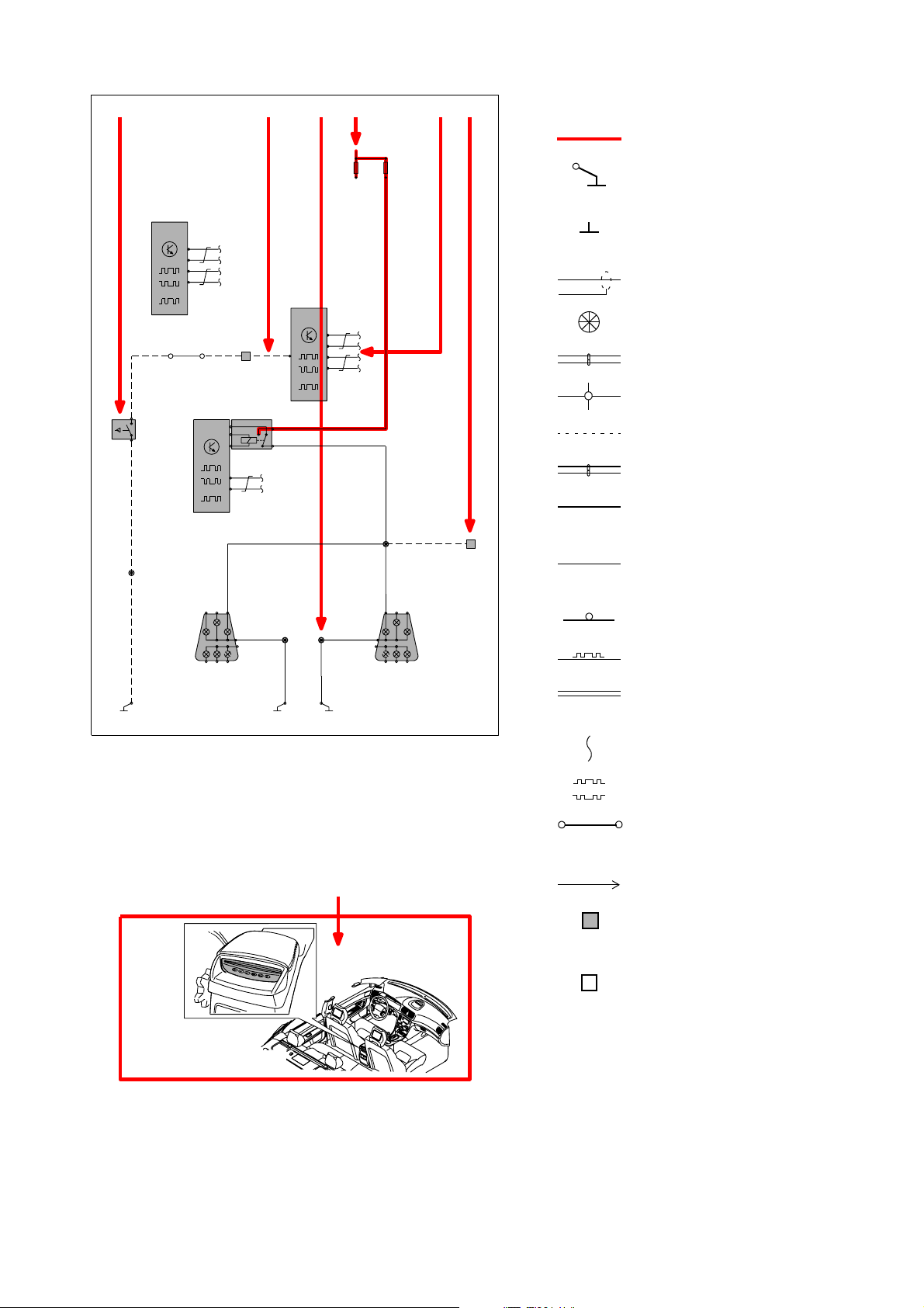
How to use the wiring diagram 2:2
A
4/28
TCM
B:1
B:13
B:2
CAN
B:14
15/20:13
Y-GR Y-GR Y-GR
MAN
3/10
2
1
SB
MAN
53/326
SB
31/96
15/24:2
REM
10/18
F BD E C
List of symbols
30+
11
11D/3
11D/4
2
2
R
4/56
CEM
D:2
54/3LF
A:1
3
4/58
CAN
2/80
RMI4
4
5
3
1
2
1
3
A:14
A:16
B:3
53/601
B:1
SB
31/72
D:3
B:17
CAN
B:18
BL
54/51
BL
12
SB
31/73
53/615
BL
10/17
B:3
10/4810/55
B:1
SB
BL
53/604
SB
= System voltage
= Ground connection
via wiring
= Ground connection on
component/chassis
= Screened wire
= Junction point
= Twisted cable
= Electrical connection
= Variant
= CAN communication
= CAN high data signal
(CAN H)
= CAN low data signal
(CAN L)
= MOST communication
= LIN communication
= DIN cable, coaxial cable,
etc.
16/82
= Data communication
CAN
= CAN communication
= Connection with distribution
box
G
1
= Further connection to...
= Connector between
wiring harnesses
1
= Connector connected
to component
TP3 979 20 2 S8 0 Premier 20 05 6
Page 7
R
C1:1
R
C1:2
C3:1
C3:3
C4:2
A1:13
C4:9
SB
53/397
BN
31/93
17/17
C6:12
C6:13
C3:4
C6:4
C3:2
C4:11
C5:14
A1:1
A1:5
C4:6
SB
R
BL-R
F
R
E
D
C
CNG/LPG
A1:10
A1:11
C4:10
C6:2
R
20/16
1
53/329
SB
2
11B/24
1
11B/23
1
2
2
2/32
FMA2
3
1
5
2
11B/22
1
11A
2
8
11B/21
1
11B/20
1
2
2/14
2
2
FMA3
3
5
1
2
C4:4
C4:3
C2:2
C4:5
R-W
BL
B
A
11B/19
1
11A
22
7
11B/18
1
2
2
2/91
FST1
45
3
1
2
C6:1
C4:8
11B/17
1
2
11B/16
11A
6
1
11B/15
1
FST2
2/182
4
3
2
2
5
1
2
2/90
FST3
45
3
1
2
C6:9
C6:8
C5:15
C5:12
11B/14
1
2
11B/13
1
11A
2
5
11A
4
2 222
3
2
11B/12
1
11B/11
1
11B/10
1
11B/9
1
11B/8
1
11B/7
1
11B/6
1
11B/5
1
11B/4
11
11B/3
11B/2
1
2
2
FMI2
2/33
2/22
2/35
3
1
FMI1
3
2
FMA4
3
1
5 45 4
2
1
5
2
2
2
2
2
2
2
2
2
2
22
C6:6
C6:11
C5:2
A1:6
C5:11
C4:14
C4:15
A1:8
C4:12
C4:16
C6:10
TP397 92 02 S8 0 Premier 2 005 7
11B /1
1
11A 11A 11A
1
A1:2
C5:13
A1:3
A1:7
A1:14
C6:3
C6:7
15/30
C2:1
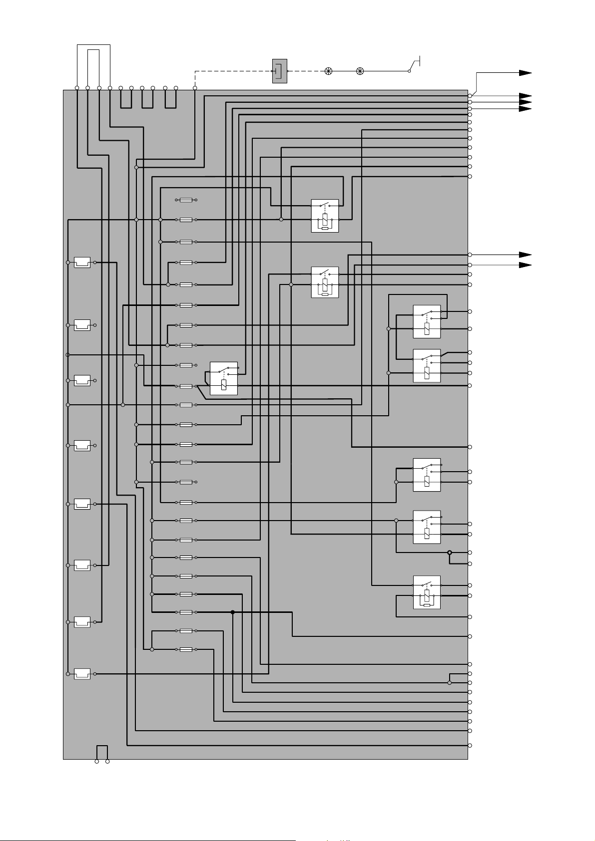
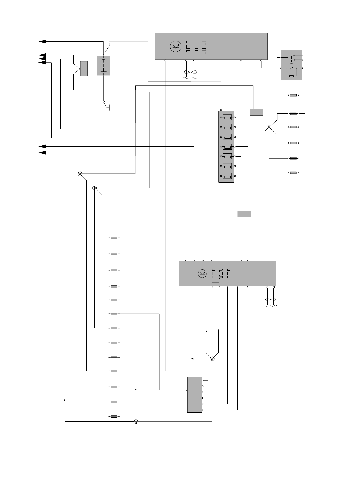
Electrical distribution 1:2
Overview S80 Premier
15/31
C4:1
A1:12
Page 8
F
E
AB DC
SB
LIN
C:14
CAN
C:13
11E
4
3
K:1
F
1
L
B
2 5
2/52
11F/6
2
1
R
R
1
1
23
R-W
2
54/40C
R
22
R
53/724
RRR
1
11
R
2
1
R
R
R
45
22
2
67
2
R
R
1 1
R
11F/12
11F/4
222
11F/3
11F/2
11F/1
2 2
R
+
12V
-
1/1
6/25:1
R
SB
REM
4/58
A:29
6/26A:1
31/53
R
BL-R
R-W
BL
53/415
53/403
3/157:1
1
2
54/40D
R
2 2
1 1
11C/1111C/1
11
11C/10
11C/9
2 22
1
11C/8
11
11C/7
11C/6
2 22
1
11C/5
1
11C/4
222
11
VO
11C/3
11C /2
1 1
2 2
4/9B:27/55
VO
VO
53/408
R-SB
BL
B:2
B:24
B:3
B:16
CEM
CAN
4/56
D:15
C:14
D:16
4/9B:28/56
3/157:2
BL-R
BL-R
Y
BL-R
BL-R
16/65:1
53/443
BL-R
8
15
1
30
4
15 15I
6
X
5
37
S
50
3/1
11C/1311C/12
R
R
R
LIN
D:60
Y-W
R
E:A
R
E:B
D:8
D:35
D:50
TP397 92 02 S8 0 Premier 2 005 8
Electrical distribution 2:2
Overview S80 Premier
VO
Page 9
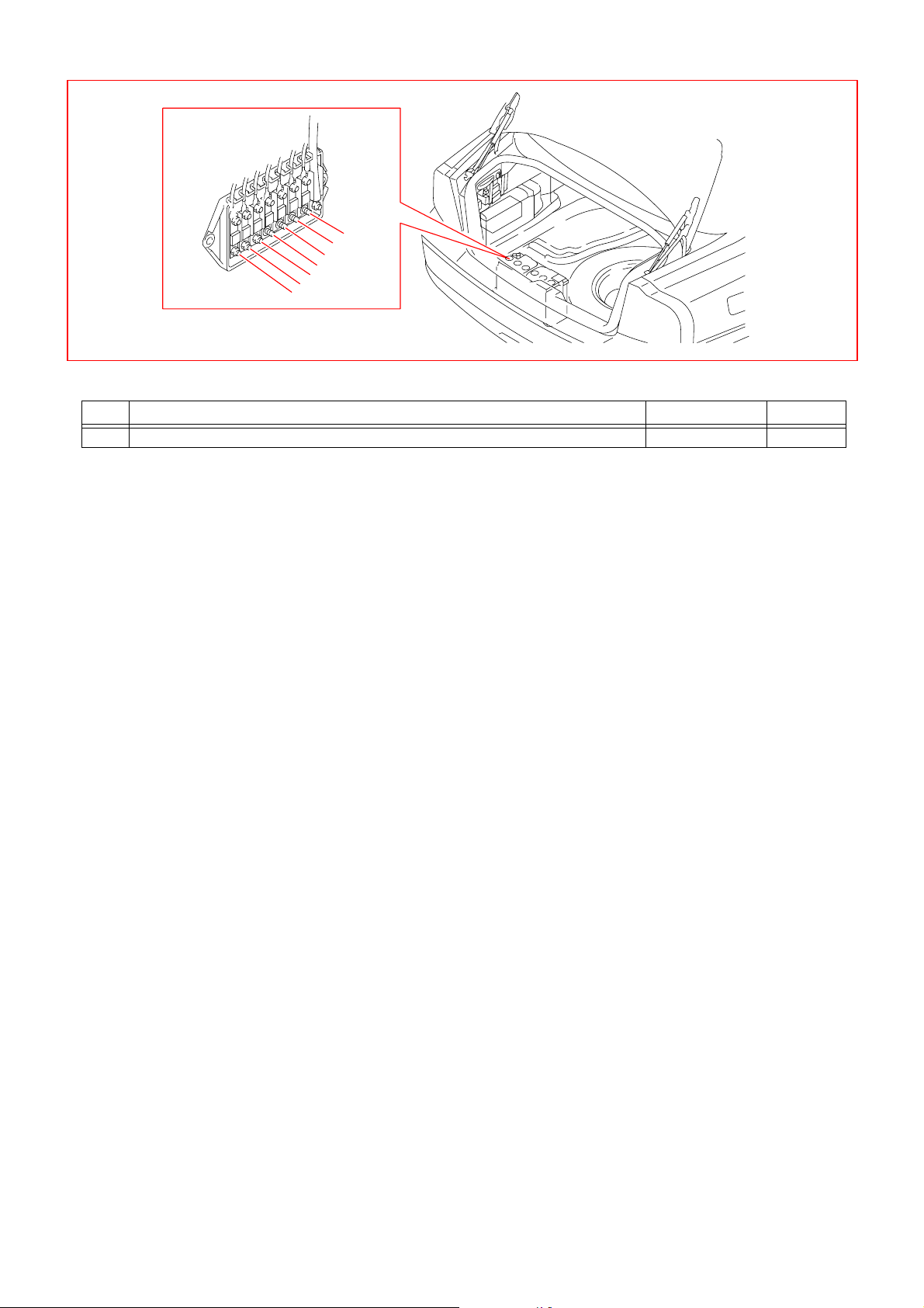
Fuses
Fuses by the battery
11E/1
11E/2
11E/3
11E/4
11E/5
11E/6
11E/7
11E Fuses by the battery
No. Fuse function via A
216/124Rear Seat Entertainment module (RSE) - 40
TP3 979 20 2 S8 0 Premier 20 05 9
Page 10
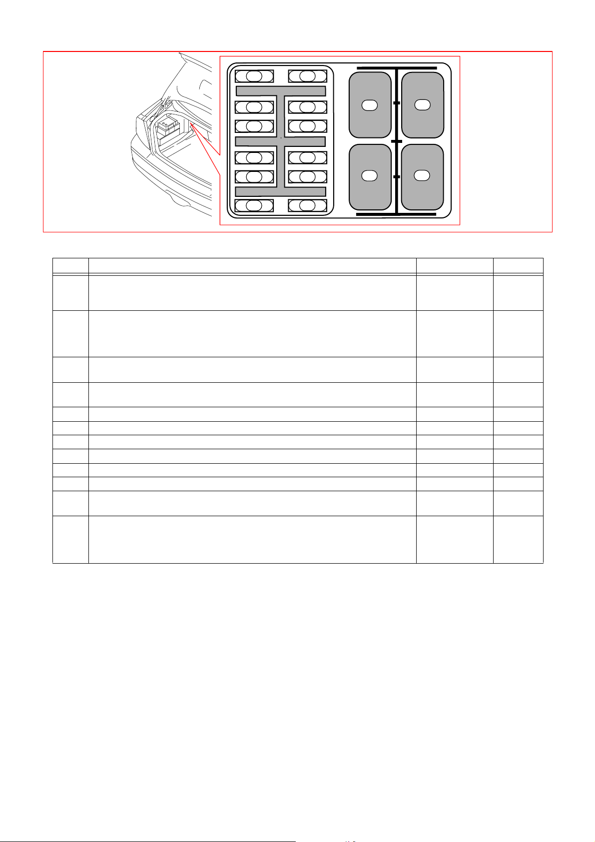
Fuses
Fuses in auxiliary fuse box
10
11
12
7
8
1
2
9
3
4
1
2
3
4
5
6
11F Fuses in cargo compartment auxiliary fuse box
No. Fuse function via A
12/52 Relay, 15l feed, rear
4/55 Sun blind control module
9/24 Coolbox rear seat
22/30 X feed overload relay
3/104 Sun blind switch
9/14 Electrically heated right-hand rear seat
9/15 Electrically heated left-hand rear seat
3 2/84 Relay, electrically heated left-hand rear seat
9/14 Electrically heated right-hand rear seat
4 2/85 Relay, electrically heated right-hand rear seat
9/15 Electrically heated left-hand rear seat
59/24 Coolbox rear seat - 10
616/124Rear Seat Entertainment module (RSE) - 5
73/64 Electrically heated rear seat switch - 5
83/64 Electrically heated rear seat switch - 5
93/104Sun blind switch - 5
10 4/55 Sun blind control module - 10
11 16 /8 3 Voice Gu ide Am plifie r modu le (VG A)
16/124 Rear Seat Entertainment module (RSE)
12 11F/6 Fuses in cargo compartment auxiliary fuse box
8/80 Control module M2D
16/83 Voice Guide Amplifier module (VGA)
16/122 Rear Audio Separation module (RAS)
-20
-10
-15
-15
-5
-10
TP3 979 20 2 S8 0 Premier 20 05 10
Page 11
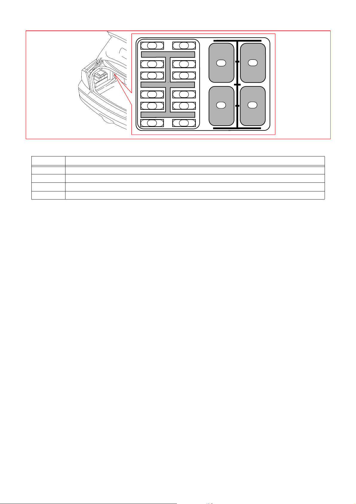
Relays
Relays in the cargo compartment
1
2
3
4
5
6
7
8
9
10
11
12
Relays in cargo compartment fuse box
Pos Relay function
2F1 2/52 Relay, 15l feed, rear
2F2 2/30 X feed overload relay
2F3 2/84 Relay, electrically heated left-hand rear seat
2F4 2/85 Relay, electrically heated right-hand rear seat
1
3
2
4
TP3 979 20 2 S8 0 Premier 20 05 11
Page 12

Ground connections
31/10 - 31/93
31/10 A-post, right-hand side
9/37 12V outlet Premier
17/21:2 12V outlet rear seat
31/48 Rear seat support, right-hand side
3/64:5 Electrically heated rear seat switch
3/104:2 Sun blind switch
4/55A:1 Sun blind control module
9/14:1 Sun blind control module
9/15:1 Electrically heated left-hand rear seat
9/24:3 Coolbox rear seat
31/53 Firewall
1/1 Battery
31/72 Rear seat support, left-hand side
8/80A Control module M2D
16/36A TV receiver
16/83B Voice Guide Amplifier module (VGA)
16/122 Rear Audio Separation module (RAS)
16/124 Rear Seat Entertainment module (RSE)
31/93 Left MacPherson strut tower
20/16B Capacitor
TP3 979 20 2 S8 0 Premier 20 05 12
Page 13

1
2 534
VO
VO
VO
SB
9/25
31/48
54/36
1
11F /2
2
11
F11
2 3
CEM
4/56
D:12
A:17
CAN
41 2 3 85 6 7
54/272A
31/10
VO
SB
SB
SB
Y-VO
Four-C
SB
Four-C
W/O Four-C
9/1
54/272B
Y/W
VO
R
VO
53/406
SB
SB
54/33
1 2 3
Y/W
SB
SB
B1 B3
1
1
2
2
SB
Y/W
10/72
BL
R
2/30
53/550
53/551
53/723
53/724
30+
11E/2
2
1
1
2
Group 36 Additional electrical equipment
12 V outlet
TP3 979 20 2 S8 0 Premier 20 05 13
Page 14

8
7
6
5
4
DVD
16/82
87
6
4
2
1
10
9
8
7
6
5
TFT
4
3
2
1
SP RIGHT
AMP
SP LEFT
11
8 12
DVD
7
6 109
5
4
M2D
CAN
2
8/80
A:1
A:7
A:2
A:8
RA:6
GN
SCRN
W
BN
7
W
62
BN
GN
2
1
AMP
2
1
2
1
2
1
R-W
2
1
2
1
16/36
SB
R
BL
GN
SB/W
BL-W
GN-W
TV-TUNER
A:1
181513 232221
A:2
A:8
A:9
A:7
GR
SB
A:11
Y
A:13
A:13
BN
A:15
A:9
12
SB
R
GN
BN
W
SB
11
10
9
8
Y-SPLIT
CN2
7
6
4
CONTROLBOX
2
1
12
10
9
78
CN3
56
2114
1
SB
SB
16/124
53/737
9
7
8
10
54/277
VOSBRBLP
9
7
8
10
54/275
VOSBRBLPGRYGNBN
20
185
17
15 16
14
12 13
11
10
9 19
8
76
432
1
WBNGNYGRPBLRSB
4
2
1
3
54/274
WBNGNYGRPBLRSB
4
2
1
3
54/276
6
6
5
5
5
GR
5
6
6
3
4
YGNBN
3
4
8
7
8
7
2
2
9
9
W
W
VO
VO
1
1
10
10
16/81B
98
710
63
5
TFT
4
2
1
RIGHT
IR
4 132
16/125
11F/6
1
11F/12
1
30+
11F/11
1
X
Group 39 Other, Accessories
Rear Seat Entertainment (RSE)
Y
GN
BN
W
2
2
2
1
2
3
4
16/122
R
R
3
54/305
R
R
RAS
VO
1
VO
LEFT
16/81A
GN
Y
OR
BN
W
132 54 6 8 9 1110 12
R
53/738
53/649
2
VGA
16/83
B:2
VO
B:6
GR-R
B:18
GR
B:1
B:11
R
SCRN
BN
GN
GR
Y
5
5
3
RED
R
AUX
-panel
16/123
2
21
1
421 3
5
4
WHITE
6
1
2
YELLOW
W
SB
31/72
TP397 92 02 S8 0 Premier 2 005 14
16/26
54/73
Page 15

4
5
3
2
0
1
B:4
B:1
B:3
B:2
C:2
C:1
B:4
B:1
B:3
B:2
C:2
C:1
1
4
BN
GR
Y
Y
BN
SB
BN
GR
Y
Y
BN
SB
SB
31/48
9/14
9/9
7/66
9/8
9/10
7/67
9/11
9/15
1
2 534
2/85
4352
2/84
1
2
11F/7
1
BL-
W
BL
2 2 4
1
C:1
B:2
B:3
C:2
B:1
B:4 B:4
B:1
C:2
B:3
B:2
C:1
54/272B
1 32 54 876
SB
R
BL
BL
SB
SB
53/552
53/551
SB
BL-
W
54/272A
1 32 54 876
SB
SB
SB
SB
BL-W
3/64
2
11F/8
1
VO
VO
2
11F/3
1
R
2
11F/4
1
R
R
1
2 534
VO
2
11F/2
1
BL
R
R
SB
SB
SB
53/723
53/726
53/724
2/30
53/725
53/565
53/574
53/550
30+
11E /2
2
1
Group 39 Other, Accessories
Electrically heated rear seat
TP3 979 20 2 S8 0 Premier 20 05 15
Page 16

R
31/48
1
2 534
BL
SB
1
2
11F/5
10A
BL
SB
SB
R
9/24
1
3
SB
SB
SB
BL
REM
4/58
CAN
F
BL
1
2
11F/1
R
R
2/52
53/724
53/726
53/551
53/565
53/550
30+
11E/2
2
1
Group 87 Climate control system
Coolbox rear seat
TP3 979 20 2 S8 0 Premier 20 05 16
Page 17

4
2
A:1
A:3
A:2
B:2
B:1
1
54/64
31
UP/D
30
BL
11F/1
2
1
4352
1
1
11F/10
2
R
SB
W
GN
6
3/104
5
1
2
VO/W
4/55
6/74
BL-R
R
BN
BL
31/48
SB
1
2
11F/9
M
41 2 3 85 6 7
54/272A
BL
VO
SB
SB
53/552
54/272B
VO/W
VO
4352
1
VO
SB
1
2
11F/2
R
R
R
53/724
R
BL
SB
REM
4/58
CAN
F
2/30 2/52
53/726
53/723
53/574
53/550
53/551
53/565
SB
SB
SB
30+
11E/2
2
1
Group 88 Internal equipment
Switch, sun blind
TP3 979 20 2 S8 0 Premier 20 05 17
Page 18

Connectors
54/33 - 54/64
54/33
3 pin grey
No. Rear Seat Entertainment harness 12V outlet
154/36:1 Connector
254/36:2 Connector
354/36:3 Connector
54/36
3 pin grey
No. Rear Seat Entertainment harness 12V outlet
154/33 Connector
254/33 Connector
354/33 Connector
VO
Y- W
SB
Y-VO
Y-W
SB
9/25:1 Rear 12V socket
-
9/25:2 Rear 12V socket
54/272A Connector
54/272B Connector
4/56D:12 Central Electronic Module
(CEM)
4/56D:12 Central Electronic Module
(CEM)
VO
-
SB
VO
Y-W
Y-W
54/64
4 pin grey
No. Sun blind control module Rear seat harness
14/55A:2Sun blind control module
24/55A:3Sun blind control module
3-
44/55A:1Sun blind control module
BL-R
R
-
BN
11F /10 Fuse
54/272A:5 Connector
-
2/30:2 X feed overload relay
2/52:2 Relay, 15l feed, rear
-
SB
TP3 979 20 2 S8 0 Premier 20 05 18
Page 19

Connectors
54/73 - 54/272B
54/73
2 pin grey
No. Rear Seat Entertainment harness Voice Guide Amplifier module (VGA)
116/26:1 Loudspeaker instrument board
centre
216/26:2 Loudspeaker instrument board
centre
54/272A and 54/272B
8 pin grey
No. Rear seat harness Rear seat harness
13/64:3 Electrically heated rear seat
switch
23/64:4 Electrically heated rear seat
switch
33/64:2 Electrically heated rear seat
switch
43/104:5 Sun blind switch
53/104:1 Sun blind switch
63/64:5 Electrically heated rear seat
switch
7-
82/52 Relay, 15l feed, rear
GR-R
GR
BL
BL-W
VO
VO
VO-W
SB
-
VO
16/83B:6 Voice Guide Amplifier module
(VGA)
16/83B:18 Voice Guide Amplifier module
(VGA)
11F/7 Fuse
2/84 Relay, electrically heated left-
hand rear seat
2/85 Relay, electrically heated right-
hand rear seat
11F/8:2 Fuse
11F/9:2 Fuse
54/64:2 Connector
53/GND5 Junction point
-
54/36:1 Connector
GR-R
GR
-
TP3 979 20 2 S8 0 Premier 20 05 19
Page 20

Connectors
54/274
54/274
10 pin grey
No. TV display harness Rear Seat Entertainment (RSE) harness
154/276 Connector
254/276 Connector
354/276 Connector
454/276 Connector
554/276 Connector
654/276 Connector
754/276 Connector
854/276 Connector
954/276 Connector
10 54/276 Connector
W
BN
GN
Y
GR
P
BL
R
SB
VO
16/124:1 Rear Seat Entertainment mod-
ule (RSE)
16/124:2 Rear Seat Entertainment mod-
ule (RSE)
16/124:3 Rear Seat Entertainment mod-
ule (RSE)
16/124:4 Rear Seat Entertainment mod-
ule (RSE)
16/124:5 Rear Seat Entertainment mod-
ule (RSE)
16/124:6 Rear Seat Entertainment mod-
ule (RSE)
16/124:7 Rear Seat Entertainment mod-
ule (RSE)
16/124:8 Rear Seat Entertainment mod-
ule (RSE)
16/124:9 Rear Seat Entertainment mod-
ule (RSE)
16/124:10 Rear Seat Entertainment mod-
ule (RSE)
W
BN
GN
Y
GR
P
BL
R
SB
VO
TP3 979 20 2 S8 0 Premier 20 05 20
Page 21

Connectors
54/275 - 54/276
54/275
10 pin grey
No. TV display harness Rear Seat Entertainment (RSE) harness
154/277:1Connector
254/277:2Connector
354/277:3Connector
454/277:4Connector
554/277:5Connector
654/277:6Connector
754/277:7Connector
854/277:8Connector
954/277:9Connector
10 54/277:10 Connector
W
BN
GN
Y
GR
P
BL
R
SB
VO
16/124:11 Rear Seat Entertainment mod-
ule (RSE)
16/124:12 Rear Seat Entertainment mod-
ule (RSE)
16/124:13 Rear Seat Entertainment mod-
ule (RSE)
16/124:14 Rear Seat Entertainment mod-
ule (RSE)
16/124:15 Rear Seat Entertainment mod-
ule (RSE)
16/124:16 Rear Seat Entertainment mod-
ule (RSE)
16/124:17 Rear Seat Entertainment mod-
ule (RSE)
16/124:18 Rear Seat Entertainment mod-
ule (RSE)
16/124:19 Rear Seat Entertainment mod-
ule (RSE)
16/124:20 Rear Seat Entertainment mod-
ule (RSE)
W
BN
GN
Y
GR
P
BL
R
SB
VO
54/276
10 pin grey
No. TV display TV display harness
116/81A:1TV display, LH head restraint
216/81A:2TV display, LH head restraint
316/81A:3TV display, LH head restraint
416/81A:4TV display, LH head restraint
516/81A:5TV display, LH head restraint
616/81A:6TV display, LH head restraint
716/81A:7TV display, LH head restraint
816/81A:8TV display, LH head restraint
916/81A:9TV display, LH head restraint
10 16/81A:10 TV display, LH head restraint
W
BN
GN
Y
GR
P
BL
R
SB
VO
54/274:1 Connector
54/274:2 Connector
54/274:3 Connector
54/274:4 Connector
54/274:5 Connector
54/274:6 Connector
54/274:7 Connector
54/274:8 Connector
54/274:9 Connector
54/274:10 Connector
W
BN
GN
Y
GR
P
BL
R
SB
VO
TP3 979 20 2 S8 0 Premier 20 05 21
Page 22

Connectors
54/277 - 54/305
54/277
10 pin grey
No. TV display TV display harness
116/81B:1TV display, RH head restraint
216/81B:2TV display, RH head restraint
316/81B:3TV display, RH head restraint
416/81B:4TV display, RH head restraint
516/81B:5TV display, RH head restraint
616/81B:6TV display, RH head restraint
716/81B:7TV display, RH head restraint
816/81B:8TV display, RH head restraint
916/81B:9TV display, RH head restraint
10 16/81B:10 TV display, RH head restraint
54/305
3 pin grey
W
BN
GN
Y
GR
P
BL
R
SB
VO
54/275:1 Connector
54/275:2 Connector
54/275:3 Connector
54/275:4 Connector
54/275:5 Connector
54/275:6 Connector
54/275:7 Connector
54/275:8 Connector
54/275:9 Connector
54/275:10 Connector
W
BN
GN
Y
GR
P
BL
R
SB
VO
No. Fuses in cargo compartment auxiliary
fuse box
1 11F/12 Fuse
2 11F/11 Fuse
3 11F/6 Fuse
R
VO
R
Rear Seat Entertainment (RSE) harness
53/738 Junction point
53/649 Junction point
16/124:6 Rear Seat Entertainment mod-
ule (RSE)
R
VO
R
TP3 979 20 2 S8 0 Premier 20 05 22
Page 23

VO VO
VO
53/649
16/124:1
(CN2)
54/305
2
P2S04_53-649
16/83B:2
V
VOVO
53/723
11/F8
11/F9
2/30:5
P2S04_53-723
R
R
R
R
R
R
11E/2
53/724
2
1
11/F1
11/F2
11/F3
11/F4
11/F12
P2S04_53-724
BL-W BL-W
BL-W
53/725
2/85:1
2/84:1
P2S04_53-725
54/272A
2
BL
BL
BL
BL
53/726
11/F5
11/F10
11/F7
2/52:5
P2S04_53-726
Junction points
53/550 - 53/726
53/550
9/14:1
53/551
2/84:2
2/30:2
2/52:2
53/552
53/649
53/550
SB
SB
SB
SB
SB
31/48
53/552
53/551
53/565
P2S04_53-550
53/723
SB
SB
SB
53/551
SB
SB
2/85:2
53/550
P2S04_53-551
53/724
3/104:20
3/64:50
53/565
54/272A
53/574
9/24:3
SB
SB
53/552
SB
54/272B
6
P2S04_53-552
53/725
SB
6
SB
53/565
SB
53/550
P2S04_53-565
53/726
54/64
4
SB SB
53/574
SB
53/550
9/5:1
P2S04_53-574
TP3 979 20 2 S8 0 Premier 20 05 23
Page 24

R
R
53/738
16/83B:1
16/122:1
P2S04_53-738
8/80A:9
54/305
1
Junction points
53/737 - 53/738
53/737 53/738
53/737
16/83:11
16/124:12
(CN2)
SB
SB
SB
SB
SB
16/122:13
8/80H:13
31/72
P2S04_53-737
TP3 979 20 2 S8 0 Premier 20 05 24
Page 25

Cable harness routing in vehicle
Rear Seat Entertainment (RS E) harness
16/81A
54/276
54/274
16/124
16/124
16/124
16/82
53/555
16/123
W/H REAR SEAT / RSE
53/554
16/123
16/36
8/80
16/36
8/80
MELBUS
MELBUS
16/122A
16/122B
16/17
16/81B
16/125
54/277
16/124
54/275
16/124
AMP
16/18
TP3 979 20 2 S8 0 Premier 20 05 25
Page 26

Cable harness routing in vehicle
Rear seat harness
3/64
3/104
54/36
9/37
54/272
9/14
54/64
9/24
RSE
53/724
53/554
4/59E:F
11E/2
31/48
9/15
53/723
TP3 979 20 2 S8 0 Premier 20 05 26
Page 27

Component illustrations
2/30 - 9/8
2/30 X feed overload relay
7
1
2
8
2
3
4
5
6
9
10
11
12
1
4
3
P2_S_2-30
2/52 Relay, 15l feed, rear
7
1
2
8
2
3
4
5
6
9
10
11
12
1
4
3
P2_S_2-52
2/84 Relay, electrically heated left-hand
rear seat
3/104 Sun blind switch
P2_S_3-104
4/55 Sun blind control module
P2_S_4-55
6/74 Window antenna amplifier 2
7
1
2
8
2
3
4
5
6
9
10
11
12
1
4
3
P2_S_2-84
2/85 Relay, electrically heated right-hand
rear seat
7
1
2
8
2
3
4
5
6
9
10
11
12
1
4
3
P2_S_2-85
3/64 Electrically heated rear seat switch
P2_S_6-74
8/80 Control module M2D
P2_S_8-80
9/8 Seat heating element left-hand rear
seat
P2_S_3-64
P2_S_9-8
TP3 979 20 2 S8 0 Premier 20 05 27
Page 28

Component illustrations
9/9 - 16/83
9/9 Back support heating element left-
hand rear seat
9/25 12V outlet, rear seat
P2_S_9-9
9/10 Seat heating element right-hand rear
seat
P2_S_9-10
9/11 Back support heating element right-
hand rear seat
P2_S_9-11
9/14 Electrically heated right-hand rear
seat
9/15 Electrically heated left-hand rear seat
P2_S_17-21
16/36 TV receiver
P2_S_16-36
16/81A TV display, LH head restraint
16/81B TV display, RH head restraint
P2_S_16-81A,B
16/82 DVD player rear
9/24 Coolbox rear seat
P2_S_9-14-15
P2_S_16-82
16/83 Voice Guide Amplifier module VGA
P2_S_9-24
TP3 979 20 2 S8 0 Premier 20 05 28
P2_S_16-83
Page 29

Component illustrations
16/122 - 31/93
16/122 Rear Audio Separation module (RAS)
P2_S_16-122
16/123 External equipment outlet AUX
P2_S_16-123
16/124 Rear Seat Entertainment module
(RSE)
31/10 Ground connection
P2_S_31-10_31-84
31/48 Ground connection
P2_S_31-48
31/53 Ground connection
16/125 IR transmitter
17/21 12V outlet, rear seat
P2_S_16-124
P2_S_16-125
P2_S_17-21
P2_S_31-53
31/72 Ground connection
P2_S_31-72
31/93 Ground connection
P2_S_31-93
TP3 979 20 2 S8 0 Premier 20 05 29
Page 30

Component illustrations
54/33 - 54/275B
54/33 Connector
54/36 Connector
54/272AConnector
P2_S_54-33
P2_S_54-36
54/272BConnector
P2_S_54-272B
54/274 Connector
54/275 Connector
P2_S_54-274_54-275
P2_S_54-272A
TP3 979 20 2 S8 0 Premier 20 05 30
Page 31

TP3 979 20 2 S8 0 Premier 20 05 31
Page 32

Index
Nr.
12V outlet ................................................................................... 13
A
Abbreviations ...............................................................................4
Accessories
Additional electrical equipment, Group 36 ....................... 13
....................................................................... 14, 15
C
Cable harness routing in vehicle ........................................ 25
Climate control system, Group 87 ...................................... 16
Colour abbreviations
Component illustrations ......................................................... 27
Connectors ................................................................................ 18
Coolbox rear seat
Countries/Markets, abbreviations ..........................................4
.................................................................4
.................................................................... 16
E
Electrical distribution overview ...............................................7
Electrically heated rear seat .................................................15
F
Fuses by the battery, 11E ........................................................ 9
Fuses in cargo compartment auxiliary fuse box, 11F
.. 10
G
Ground connections ............................................................... 12
Groups ...........................................................................................4
H
How to use the wiring diagrams ............................................5
I
Ignition switch symbols ............................................................. 4
Internal equipment, Group 88
.............................................. 17
J
Junction points ......................................................................... 23
L
List of components ..................................................................33
List of symbols .............................................................................6
O
Other, Group 39 ....................................................................... 14
R
Rear Seat Entertainment (RSE) ......................................... 14
Rear Seat Entertainment (RSE) harness ........................ 25
Rear seat harness
Relays in cargo compartment fuse box ............................ 11
................................................................... 26
S
Switch, sun blind ...................................................................... 17
T
Table of Contents .......................................................................3
TP3 979 20 2 S8 0 Premier 20 05
Page 33

List of components
2/30 X feed overload relay
2/52 Relay, 15l feed, rear
2/84 Relay, electrically heated left-hand rear seat
2/85 Relay, electrically heated right-hand rear
seat
3/64 Electrically heated rear seat switch
3/104 Sun blind switch
4/55 Sun blind control module
6/74 Window antenna amplifier 2
8/80 Control module M2D
9/8 Seat heating element left-hand rear seat
9/9 Back support heating element left-hand rear
seat
9/10 Seat heating element right-hand rear seat
9/11 Back support heating element right-hand
rear seat
9/14 Electrically heated right-hand rear seat
9/15 Electrically heated left-hand rear seat
9/24 Coolbox rear seat
9/25 12V outlet, rear seat
16/36 TV receiver
16/81A TV display, LH head restraint
16/81B TV display, RH head restraint
16/82 DVD player rear
16/83 Voice Guide Amplifier module VGA
16/122 Rear Audio Separation module (RAS)
16/123 External equipment outlet AUX
16/124 Rear Seat Entertainment module (RSE)
16/125 IR transmitter
17/21 12V outlet, rear seat
31/10 Ground connection
31/48 Ground connection
31/53 Ground connection
31/72 Ground connection
31/93 Ground connection
54/33 Connector
54/36 Connector
54/272A Connector
54/272B Connector
54/274 Connector
54/275 Connector
TP3 979 20 2 S8 0 Premier 20 05 33
Page 34

TP 3 97 92 02 ( US Engl ish) . Pri nted i n Sw ede n, G oth enbu rg 06 -20 04
Page 35

Index
Nr.
12V outlet ................................................................................... 13
A
Abbreviations ............................................................................... 4
Accessories
Additional electrical equipment, Group 36 ....................... 13
....................................................................... 14, 15
C
Cable harness routing in vehicle ........................................ 25
Climate control system, Group 87 ...................................... 16
Colour abbreviations
Component illustrations ......................................................... 27
Connectors ................................................................................ 18
Coolbox rear seat
Countries/Markets, abbreviations ..........................................4
.................................................................4
.................................................................... 16
E
Electrical distribution overview ............................................... 7
Electrically heated rear seat ................................................. 15
F
Fuses by the battery, 11E ........................................................ 9
Fuses in cargo compartment auxiliary fuse box, 11F
.. 10
G
Ground connections ............................................................... 12
Groups ...........................................................................................4
H
How to use the wiring diagrams ............................................ 5
I
Ignition switch symbols ............................................................. 4
Internal equipment, Group 88
.............................................. 17
J
Junction points ......................................................................... 23
L
List of components .................................................................. 33
List of symbols ............................................................................. 6
O
Other, Group 39 ....................................................................... 14
R
Rear Seat Entertainment (RSE) ......................................... 14
Rear Seat Entertainment (RSE) harness ........................ 25
Rear seat harness
Relays in cargo compartment fuse box ............................ 11
................................................................... 26
S
Switch, sun blind ...................................................................... 17
T
Table of Contents .......................................................................3
TP3 9 79 20 2 S8 0 Pr emier 20 05
Page 36

List of components
2/30 X feed overload relay
2/52 Relay, 15l feed, rear
2/84 Relay, electrically heated left-hand rear seat
2/85 Relay, electrically heated right-hand rear
seat
3/64 Electrically heated rear seat switch
3/104 Sun blind switch
4/55 Sun blind control module
6/74 Window antenna amplifier 2
8/80 Control module M2D
9/8 Seat heating element left-hand rear seat
9/9 Back support heating element left-hand rear
seat
9/10 Seat heating element right-hand rear seat
9/11 Back support heating element right-hand
rear seat
9/14 Electrically heated right-hand rear seat
9/15 Electrically heated left-hand rear seat
9/24 Coolbox rear seat
9/25 12V outlet, rear seat
16/36 TV receiver
16/81A TV display, LH head restraint
16/81B TV display, RH head restraint
16/82 DVD player rear
16/83 Voice Guide Amplifier module VGA
16/122 Rear Audio Separation module (RAS)
16/123 External equipment outlet AUX
16/124 Rear Seat Entertainment module (RSE)
16/125 IR transmitter
17/21 12V outlet, rear seat
31/10 Ground connection
31/48 Ground connection
31/53 Ground connection
31/72 Ground connection
31/93 Ground connection
54/33 Connector
54/36 Connector
54/272A Connector
54/272B Connector
54/274 Connector
54/275 Connector
TP3 9 79 20 2 S8 0 Pr emier 20 05 33
Page 37

Table of Contents
Vehicles with SRS (Airbag)/SIPS bag/IC
(Inflatable curtain).......................................................... 2
Abbreviations................................................................. 4
How to use the wiring diagram 1:2 ................................ 5
Electrical distribution 1:2................................................ 7
Fuses
Fuses by the battery ....................................................... 9
Fuses in auxiliary fuse box ........................................... 10
Relays
Relays in the cargo compartment................................ 11
Ground connections
31/10 - 31/93 ............................................................... 12
Group 36 Additional electrical equipment
12 V outlet ................................................................... 13
Group 39 Other, Accessories
Rear Seat Entertainment (RSE) .................................. 14
Electrically heated rear seat ........................................ 15
Group 87 Climate control system
Coolbox rear seat ........................................................ 16
Group 88 Internal equipment
Switch, sun blind.......................................................... 17
Connectors
54/33 - 54/64................................................................ 18
54/73 - 54/272B ........................................................... 19
54/274 ........................................................................ 20
54/275 - 54/276............................................................ 21
54/277 - 54/305............................................................ 22
Junction points
53/550 - 53/726............................................................ 23
53/737 - 53/738............................................................ 24
Cable harness routing in vehicle
Rear Seat Entertainment (RSE) harness......................25
Rear seat harness ........................................................26
Component illustrations
2/30 - 9/8...................................................................... 27
9/9 - 16/83.................................................................... 28
16/122 - 31/93.............................................................. 29
54/33 - 54/275B ........................................................... 30
Index
List of components
TP3 979 20 2 S8 0 Pr emier 20 05
 Loading...