

Page 1

OWNER'S MANUAL
Page 2

Page 3

VÄLKOMMEN!
We trust that you will enjoy many years of safe driving in your Volvo, an
automobile designed with your safety and comfort in mind. To help get
the most from your Volvo, we urge you to familiarize yourself with the
instructions and maintenance information in this owner’s manual. The
owner’s manual can also be found in a mobile app (Volvo manual) and
on Volvo Car’s support site at support.volvocars.com.
We also urge you and your passengers to wear seat belts at all times in
this (or any other) vehicle. And, of course, please do not operate a vehi-
cle if you may be affected by alcohol, medication or any impairment that
could hinder your ability to drive.
Your Volvo is designed to meet all applicable federal safety and emission standards. If you have any questions regarding your vehicle, please
contact your Volvo retailer or see the article "Contacting Volvo" for information on getting in touch with Volvo in the United States and Canada.
Page 4

2
INTRODUCTION
On-board owner's manual
10
Owner's information
12
Contacting Volvo
13
About this manual
13
Change of ownership
17
Crash event data
17
Volvo Structural Parts Statement
18
Information on the Internet
19
Volvo ID
20
Open Source Software Notice
20
Volvo and the environment
21
Important warnings
22
Volvo Roadside Assistance
23
Technician certification
23
SAFETY
Occupant safety
26
Recall information
26
Reporting safety defects
27
Seat belts – general
28
Seat belts – buckling/unbuckling
29
Seat belt reminder
30
Seat belts – pregnancy
31
Supplemental Restraint System (SRS)
31
Front airbags
33
Occupant Weight Sensor
36
Side impact protection (SIPS) airbags
39
Inflatable Curtain (IC)
41
Whiplash Protection System (WHIPS)
42
Crash mode – general information
44
Crash mode – starting the vehicle
45
Crash mode – moving the vehicle
45
Child safety
46
Child restraints
47
Infant seats
49
Convertible seats
52
Booster cushions
54
ISOFIX/LATCH lower anchors
55
Top tether anchors
56
Child safety locks
58
INSTRUMENTS AND CONTROLS
Instrument overview
60
Information displays – introduction
63
Eco Guide* and Power Meter*
66
Information displays – indicator symbols
67
Information displays – warning symbols
69
My Car – introduction
71
Information displays – ambient temperature sensor
72
Information displays – trip odometer
and clock
73
Inserting/removing remote key
73
Ignition modes
74
Front seats
75
Front seats – folding backrest*
76
Front seats – power seat
76
Key memory – power driver's seat*
and door mirrors
78
Rear seats – head restraints
79
Rear seats – folding backrest
81
Steering wheel
82
Electrically heated* steering wheel
83
Lighting panel
83
High/low beam headlights
84
Active high beams (AHB)*
85
Tunnel detection (models with the
rain sensor* only)
86
TABLE OF CONTENTS
Page 5

3
Active Bending Lights (ABL)*
86
Auxiliary lights*
87
Instrument and "theater" lighting
88
Parking lights
88
Rear fog lights
89
Hazard warning flashers
89
Turn signals
90
Front interior lighting
91
Rear interior lighting
92
Home safe lighting
92
Approach lighting
92
Windshield wipers
93
Rain sensor*
94
Windshield washer
94
Tailgate wiper/washer
95
Power windows
96
Sun shades
97
Power door mirrors
97
Power door mirrors – automatic tilting/retraction
98
Heated windshield*, rear window and
door mirror defrosters
99
Interior rearview mirror
100
Digital compass*
100
Power moonroof – introduction
101
Power moonroof – operation
102
HomeLink® Wireless Control System* – introduction
103
HomeLink® Wireless Control System* – programming
104
Volvo Sensus
107
Information display – menu controls
108
Information display – menu overview
108
Information display – messages
109
Trip computer – introduction
110
Trip computer – functions, analog
instrument panel
111
Trip computer – functions, digital
instrument panel
114
Trip computer – Supplementary
information
116
Trip computer – Trip statistics
117
CLIMATE
Climate – general information
120
Climate – sensors
121
Air quality
121
Interior Air Quality System (IAQS)*
122
Climate – menu settings
123
Air distribution – general
123
Electronic climate control (ECC)
125
Heated seats
126
Temperature and blower control
127
Automatic climate control
127
Air conditioning
128
Max. defroster and electrically heated
windshield*
128
Air distribution – function
129
Air distribution – recirculation
130
Air distribution – table
131
Page 6

4
LOADING AND STORAGE
Storage spaces
134
Tunnel console
136
Tunnel console – 12-volt sockets
136
Glove compartment
137
Vanity mirror
137
12-volt socket in the trunk*
137
Loading – general
138
Ski hatch
138
Loading – roof load carriers
139
Load anchoring eyelets
140
Grocery bag holder
141
LOCKS AND ALARM
Remote key and key blade
144
Remote key – loss
144
Key memory
145
Locking/unlocking confirmation
146
Immobilizer (start inhibitor)
146
Remote key – functions
147
Remote key – range
148
Detachable key blade – general
information
149
Detachable key blade – detaching/
reinserting
149
Detachable key blade – unlocking
150
Valet locking
150
Remote key – replacing the battery
151
Keyless drive*– locking/unlocking
153
Keyless drive* – unlocking with key blade
154
Keyless drive* – key memory
155
Keyless drive* – messages
155
Keyless drive* – antenna locations
156
Locking/unlocking – from the outside
157
Manual locking
158
Locking/unlocking – from inside
158
Locking/unlocking – glove compartment
160
Locking/unlocking – trunk
160
Alarm – general information
162
Alarm indicator
162
Alarm – arming/disarming
163
Alarm signal
163
Alarm – turning off
164
Alarm-related functions
164
Page 7

5
DRIVER SUPPORT
Stability system – introduction
166
Stability system – operation
167
Stability system – symbols and messages
168
Adjustable steering force*
170
Road Sign Information (RSI)* – introduction
170
Road Sign Information (RSI) – operation
171
Road Sign Information (RSI) – limitations
172
Cruise control (CC) – introduction
172
Cruise control (CC) – engaging and
setting speed
173
Toggling between ACC and CC
(standard Cruise Control)
174
Cruise control (CC) – deactivating
175
Adaptive Cruise Control – introduction
175
Adaptive Cruise Control – function
177
Adaptive Cruise Control – engaging
179
Adaptive Cruise Control – setting speed
179
Adaptive Cruise Control – setting
time interval
180
Adaptive Cruise Control – deactivating
181
Adaptive Cruise Control – passing
another vehicle
182
Adaptive Cruise Control (ACC) –
Queue Assist
183
Radar sensor
185
Adaptive Cruise Control – limitations
185
Adaptive Cruise Control – symbols
and messages
187
Adaptive Cruise Control – troubleshooting
189
Distance Alert – introduction
190
Distance Alert – operation
190
Distance Alert – limitations
191
Distance Alert – symbols and messages
193
City Safety – introduction
194
City Safety – function
195
City Safety – operation
196
City Safety – limitations
196
City Safety – troubleshooting
197
City Safety – symbols and messages
199
City Safety – Laser sensor
200
Collision warning – introduction
201
Collision warning* – function
203
Collision warning* – operation
204
Collision warning* – Cyclist detection
205
Collision warning* – Pedestrian detection
206
Collision warning* – limitations
207
The camera’s limitations
209
Collision warning – troubleshooting
210
Collision warning – symbols and
messages
212
Driver Alert System
214
Driver Alert Control (DAC) – introduction
214
Driver Alert Control (DAC) – operation
215
Driver Alert Control (DAC) – function
216
Driver Alert Control (DAC) – limitations
216
Driver Alert Control (DAC) – symbols
and messages
218
Lane Departure Warning (LDW) –
introduction
220
Lane Departure Warning (LDW) –
operation
221
Lane Departure Warning (LDW) limitations
222
Lane Departure Warning (LDW) –
symbols and messages
223
Lane Keeping Aid (LKA) – introduction
225
Lane Keeping Aid (LKA) – operation
226
Lane Keeping Aid (LKA) – limitations
228
Lane Keeping Aid (LKA) – symbols
and messages
229
Park assist – introduction
230
Park assist – function
230
Park assist – operation
232
Park assist – limitations
233
Park Assist Pilot (PAP)* – introduction
234
Page 8

6
Park Assist Pilot (PAP)* – function
234
Park Assist Pilot (PAP)* – operation
235
Park Assist Pilot (PAP)* – limitations
237
Park Assist Pilot (PAP)* – symbols
and messages
238
Park assist – troubleshooting
238
Rear Park Assist Camera (PAC) –
introduction
239
Rear Park Assist Camera (PAC) –
function
239
Rear Park Assist Camera (PAC) –
operation
240
Rear Park Assist Camera (PAC) –
guiding and marker lines
241
Rear Park Assist Camera (PAC) –
limitations
243
BLIS* – introduction
243
BLIS* – function
244
BLIS* – operation
245
BLIS* – Cross Traffic Alert (CTA)
246
BLIS* – limitations
247
BLIS* – messages
248
STARTING AND DRIVING
Starting the engine
250
Switching off the engine
252
Engine Remote Start (ERS)* – introduction
252
Engine Remote Start (ERS)* – starting the engine
253
Engine Remote Start (ERS)* –
switching off the engine
253
Jump starting
254
Transmission – general information
255
Transmission – positions
255
Transmission – Geartronic
257
Transmission – shiftlock override
259
Start/Stop – Hill Start Assist (HSA)
260
Start/Stop – introduction
260
Start/Stop – function
261
Start/Stop – Auto-stop exceptions
262
Start/Stop – Auto-start exceptions
262
Start/Stop – settings
263
Start/Stop – symbols and messages
264
ECO*
265
All Wheel Drive (AWD)
267
Brakes – general
267
Brakes – symbols
269
Anti-lock braking system (ABS)
269
Brake lights
270
Emergency Brake Assistance (EBA)
270
Parking brake – general information
271
Parking brake – applying
271
Parking brake – releasing
272
Parking brake – symbols and messages
274
Driving through water
275
Engine and cooling system
275
Conserving electrical current
276
Before a long distance trip
276
Driving in cold weather
277
Refueling – fuel requirements
277
Refueling – octane rating
278
Refueling – opening/closing fuel
filler door
280
Refueling – opening/closing fuel cap
281
Emission controls
281
Economical driving
282
Towing a trailer
283
Trailer Stability Assist (TSA)
285
Towing the vehicle
286
Towing eyelet
286
Towing by tow truck
287
Page 9

7
WHEELS AND TIRES
Tires – general information
290
Tires – storage and age
291
Tires – tread wear indicator
292
Tires – tire economy
292
Changing a wheel – direction of rotation
293
Changing a wheel – removing wheel
293
Changing a wheel – spare wheel
296
Changing a wheel – accessing the
spare wheel
297
Changing a wheel – installing a wheel
297
Tire inflation – general information
298
Tire inflation – checking pressure
299
Tire specifications
300
Loading specifications
302
Loading specifications – load limit
302
Tire specifications – terminology
303
Tire specifications – Uniform Tire
Quality Grading
304
Snow chains
305
Snow tires/studded tires
306
Tire pressure monitoring - overview
306
Tire Monitor - introduction
307
Calibrating Tire Monitor
308
Tire Monitor status information
309
Tire Monitor – messages
309
Tire Pressure Monitoring System
(TPMS) – general information
310
Tire Pressure Monitoring System
(TPMS) – changing wheels
311
Tire Pressure Monitoring System
(TPMS) – recalibrating
312
Tire Pressure Monitoring System
(TPMS) – activating/deactivating
312
Tire Pressure Monitoring System
(TPMS) – messages
313
Tire sealing system* – general information
314
Tire sealing system* – overview
315
Tire sealing system* – sealing a hole
317
Tire sealing system – checking inflation pressure
319
Tire sealing system* – inflating tires
319
Tire sealing system* – sealing compound container
320
MAINTENANCE AND SERVICING
Maintenance – introduction
322
Maintenance – owner maintenance
323
Maintenance – hoisting
324
Onboard Diagnostic System
325
Booking service and repairs
325
Maintenance – opening/closing hood
327
Engine compartment – overview
328
Engine compartment – engine oil
329
Engine compartment – coolant
332
Engine compartment – brake fluid
333
Engine compartment – power steering fluid
333
Bulbs – introduction
334
Bulbs – headlight housing
335
Bulbs – cover
336
Bulbs – low beam, Halogen
337
Bulbs – high beam, Halogen
337
Bulbs – extra high beam
338
Bulbs – front turn signals
338
Bulbs – location of taillight bulbs
339
Bulbs – taillight housing
340
Bulbs – license plate lighting
340
Bulbs – trunk lighting
341
Bulbs – vanity mirror lighting
341
Bulbs – specifications
341
Page 10

8
Wiper blades – service position
342
Wiper blades – windshield
343
Engine compartment – washer fluid
344
Battery – symbols
344
Battery – handling
345
Battery – maintenance
346
Battery – changing
347
Fuses – introduction
349
Fuses – engine compartment
350
Fuses – glove compartment
353
Fuses – cargo area/trunk
356
Fuses – engine compartment cold
zone (Start/Stop only)
357
Washing the vehicle
359
Automatic car wash
360
Polishing and waxing
361
Cleaning the interior
361
Touching up paintwork
363
SPECIFICATIONS
Label information
366
Dimensions
369
Weights
371
Engine specifications
372
Oil specifications
373
Oil volume
374
Coolant – specification and volume
375
Transmission oil – specification and
volumes
375
Brake fluid – specification and volume
375
Power steering – specification
376
Fuel tank volume – specification and
volume
376
Tire inflation – pressure table
377
Air conditioning – specification and
volume
378
Battery specifications
378
Symbols – general information
378
Warning symbols
379
Indicator symbols
380
Information symbols
380
Information symbols – ceiling console
381
Information symbols – center console
382
INDEX
Index 383
Page 11

INTRODUCTION
Page 12
INTRODUCTION
10
On-board owner's manual
The owner's manual can be displayed on the
center console screen and you can carry out
searches for the information that you require.
To open the owner's manual, press the MY CAR
button on the center console, press OK/MENU
and select
Owner's manual.
For basic information, see "Infotainment - operating the system." The following sections also provide more detailed information.
The on-board owner's manual start page
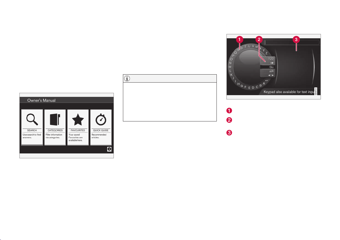
There are four ways of finding information articles
in the on-board owner's manual:
•
Searching: search for an article.
•
Categories: All of the articles are sorted by
category.
•
Favorites: Quick access to frequently read
articles.
•
Quick Guide: A selection of articles cover-
ing commonly used functions.
Select the symbol in the lower right-hand corner
for additional information about the on-board
owner's manual.
NOTE
•
The on-board owner's manual cannot be
accessed while the vehicle is moving.
•
Specifications regarding your vehicle are
not found in the on-board information.
This information is listed in the printed
owner's manual.
Searching for information
Searching using the text wheel
List of characters
Switching between character entry modes
(see the following table)
Surf history
Use the text wheel to enter a web address.
1.
Turn TUNE to the desired letter and press
OK/MENU to confirm. The number/letter
keys on the center console can also be used.
2. Continue to the next letter, etc. The results of
the search will be displayed in the phone
book.
Page 13
INTRODUCTION
}}
11
3. To switch from letter entry mode to the entry
mode for numbers or special characters, or
to go view surf history, turn TUNE to one of
the selections (see the explanation in the following table) in the list for switching character entry mode (2) and press OK/MENU.
123/A
BC
Toggle between letters and numbers by pressing OK/MENU.
=>
This leads to surf history. Turn
TUNE to select a web address and
press OK/MENU to go to the website.
Go
Go to the website by pressing OK/
MENU.
a|A
Toggle between upper and lower
case letters by pressing OK/MENU.
| | }
Switch from the text wheel to the
Address: field. Use TUNE to move
the cursor and erase characters by
pressing EXIT. Press OK/MENU to
return to the text wheel.
The number/letter keys on the center console can also be used to edit
the
Address: field.
Press EXIT briefly to erase a single character.
Press and hold EXIT to erase all characters.
Pressing a number key on the center console
while the text wheel is displayed (see the previous illustration) will display a list of characters.
Press the desired key repeatedly to enter the
desired letter and continue to the next letter, etc.
To enter a number, press and hold the button.
Categories
The articles in the on-board owner's manual are
divided into main categories and sub-categories.
The same article may be listed in several applicable categories to help make searches easier.
Turn TUNE to navigate in the category structure
and press OK/MENU to open a category (indi-
cated by the
symbol) or an article (indicated
by the
symbol). Press EXIT to return to the
previous view.
Favorites
Articles that have been marked as favorites can
be found here. For information about marking an
article as a favorite, see "Navigating in an article"
below.
Turn TUNE to navigate in the list of favorites and
press OK/MENU to open an article. Press EXIT
to return to the previous view.
Quick Guide
This is a selection of articles that will help you
become familiar with some of the vehicle's most
common functions. These articles can also be
found in their respective categories but are listed
here for quick access.
Turn TUNE to navigate in the Quick Guide and
press OK/MENU to open an article. Press EXIT
to return to the previous view.
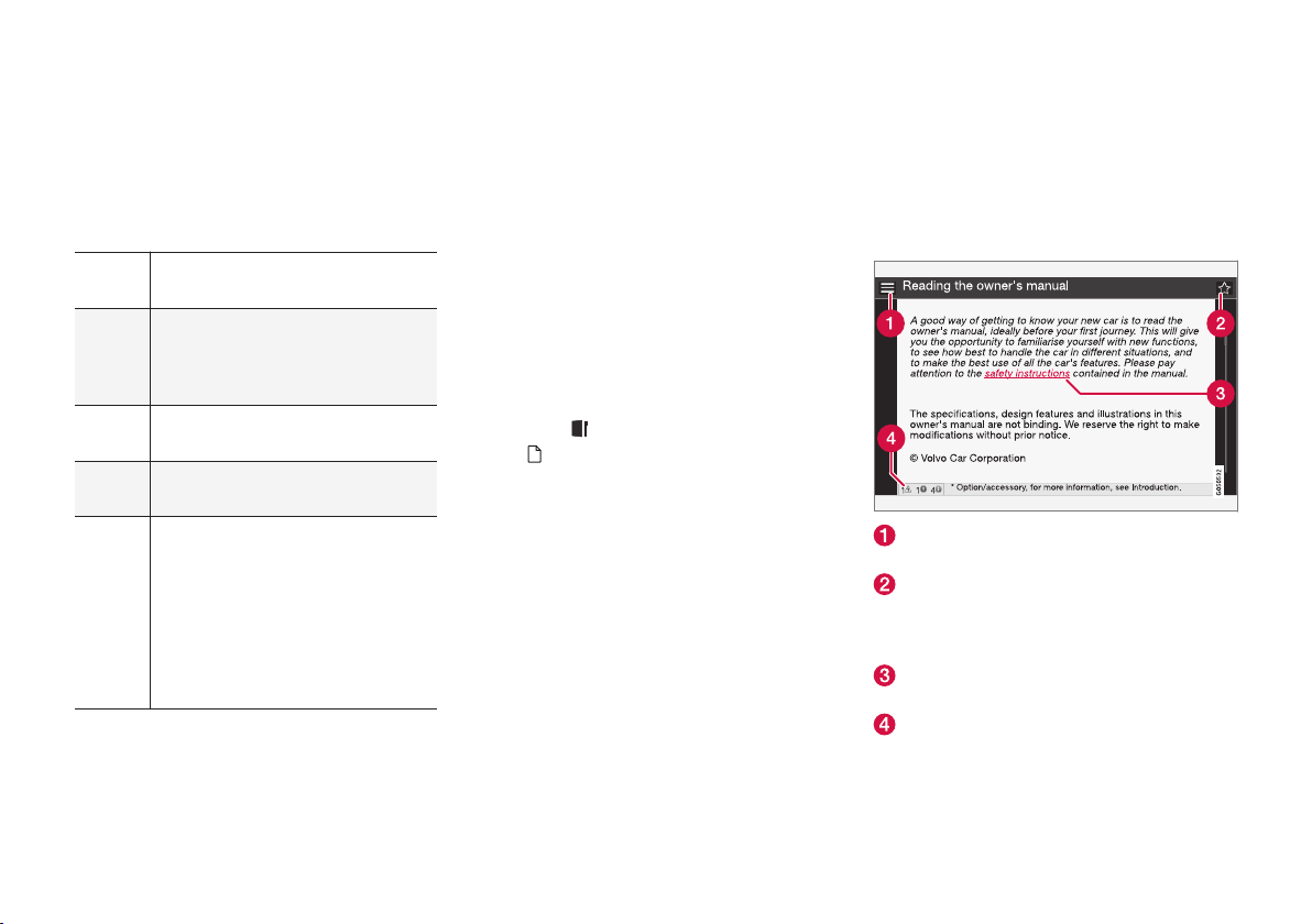
Navigating in an article
Home: Returns you to the owner's manual
start page.
Favorites: Add/remove an article from the
list of favorites. This can also be done by
pressing the FAV button on the center console keypad.
Highlighted link: takes you to the linked
article.
Important information: if the article contains warnings, cautions or notes, symbols for
these types of information and the number of
Page 14

||
INTRODUCTION
12
such texts in the article will be displayed
here.
Turn TUNE to navigate among the links or scroll
in an article. When you have scrolled to the
beginning/end of an article, you can return to the
start page or a favorite by scrolling one additional
step up/down. Press OK/MENU to activate a
selection or highlighted link. Press EXIT to return
to the previous view.
Related information
•
Information on the Internet (p. 19)
Owner's information
Your vehicle is equipped with a screen on which
you can display information about your vehicle's
features and functions. The printed owner's
manual supplements the on-board information
and contains important texts, the latest updates
and instructions that can be useful in situations
when it is not practical to read the information on
the screen.
Changing the language used for the on-board
information could mean that some of the information displayed may not comply with national
or local statutes and regulations.
NOTE
•
Do not export your Volvo to another
country before investigating that country's applicable safety and exhaust emission requirements. In some cases it may
be difficult or impossible to comply with
these requirements. Modifications to the
emission control system(s) may render
your Volvo not certifiable for legal operation in the U.S., Canada and other countries.
•
All information, illustrations and specifications contained in this manual are based
on the latest product information available at the time of publication. Please note
that some vehicles may be equipped differently, depending on market-specific
adaptations or special legal requirements.
Optional equipment described in this
manual may not be available in all markets.
•
Some of the illustrations shown are
generic and are intended as examples
only, and may not depict the exact model
for which this owner's information is
intended.
•
Volvo reserves the right to make model
and product changes at any time, or to
change specifications or design without
notice and without incurring obligation.
Page 15
INTRODUCTION
}}
13
WARNING
The driver is always responsible for operating
the vehicle in a safe manner and for complying with current statutes and regulations.
It is also essential to maintain and service the
vehicle according to Volvo's recommendations
as stated in the owner's information and the
service and warranty booklet.
If the on-board information differs from the
printed owner's manual, the printed information always takes precedence.
Contacting Volvo
In the USA:
Volvo Car USA, LLC
Customer Care Center
1 Volvo Drive,
P.O. Box 914
Rockleigh, New Jersey 07647
1-800-458-1552
www.volvocars.com/us
In Canada:
Volvo Car Canada Ltd.
Customer Care Centre
9130 Leslie Street, Suite 101
Richmond Hill, Ontario L4B 0B9
1-800-663-8255
www.volvocars.com/ca
Related information
•
About this manual (p. 13)
•
Important warnings (p. 22)
•
Crash event data (p. 17)
•
Volvo Structural Parts Statement (p. 18)
About this manual
Reading your owner's manual is a good way to
familiarize yourself with the features and systems
in your vehicle.
•
Before you operate your vehicle for the first
time, we recommend that you look through
the information found in the chapters "Your
Driving Environment" and "During Your Trip."
•
Information contained in the balance of the
manual is extremely useful and should be
read after operating the vehicle for the first
time.
•
The manual is structured so that it can be
used for reference. For this reason, it should
be kept in the vehicle for ready access.
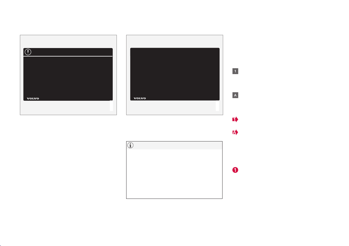
On-board owner's manual
When the printed manual refers to the on-board
owner's manual, this pertains to the information
displayed on the center console screen.
The language used on the center console screen
and instrument panel can be changed in the
MY
CAR system settings menu.
NOTE
Please be aware that changing languages to
one that you do not understand may make it
difficult to change back to the original language.
Page 16
||
INTRODUCTION
14
There are four ways of finding information articles
in the on-board owner's manual:
•
Searching: search for an article.
•
Categories: All of the articles are sorted by
category.
•
Favorites: Quick access to frequently read
articles.
•
Quick Guide: A selection of articles cover-
ing commonly used functions.
Select the symbol in the lower right-hand corner
for additional information about the on-board
owner's manual.
NOTE
•
The on-board owner's manual cannot be
accessed while the vehicle is moving.
•
Specifications regarding your vehicle are
not found in the on-board information.
This information is listed in the printed
owner's manual.
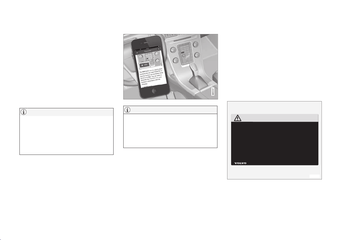
The owner's manual in mobile devices
NOTE
The owner's manual mobile app can be downloaded at www.volvocars.com.
The mobile app also contains videos and
searchable content, and provides easy navigation between the various articles.
Footnotes
Certain pages of this manual contain information
in the form of footnotes at the bottom of the
page. This information supplements the text that
the footnote number refers to (a letter is used if
the footnote refers to text in a table).
Display texts
There are several displays in the driver’s field of
vision that show messages generated by various
systems and functions in the vehicle. These texts
are indicated in the Owner’s Manual by being in
slightly larger type than the surrounding text and
are printed in gray, (for example:
Change doors
unlock setting).
Decals
There are various types of decals in the vehicle
whose purpose is to provide important information in a clear and concise way. The importance
of these decals is explained as follows, in
descending order of importance.
Risk of injury
G031590
Black ISO symbols on a yellow warning background, white text/image on a black background.
Decals of this type are used to indicate potential
danger. Ignoring a warning of this type could
result in serious injury or death.
Page 17
INTRODUCTION
}}
15
Risk of damage to the vehicle
G031592
White ISO symbols and white text/image on a
black or blue warning background and space for
a message. If the information on decals of this
type is ignored, damage to the vehicle could
result.
Information
G031593
White ISO symbols and white text/image on a
black background. These decals provide general
information.
NOTE
The decals shown in the Owner’s Manual are
examples only and are not intended to be
reproductions of the decals actually used in
the vehicle. The purpose is to give an indication of how they look and their approximate
location in the vehicle. The applicable information for your particular vehicle can be
found on the respective decals in the vehicle.
Types of lists used in the owner's information
Procedures
Procedures (step-by-step instructions), or actions
that must be carried out in a certain order, are
arranged in numbered lists in this manual.
If there is a series of illustrations associated
with step-by-step instructions, each step in
the procedure is numbered in the same way
as the corresponding illustration.
Lists in which letters are used can be found
with series of illustrations in cases where the
order in which the instructions are carried out
is not important.
Arrows with or without numbers are used to
indicate the direction of a movement.
Arrows containing letters are used to indicate movement.
If there are no illustrations associated with a
step-by-step list, the steps in the procedure are
indicated by ordinary numbers.
Position lists
Red circles containing a number are used in
general overview illustrations in which certain
components are pointed out. The corresponding number is also used in the position
list's description of the various components.
Page 18
||
INTRODUCTION
16
Bullet lists
Bullets are used to differentiate a number of
components/functions/points of information that
can be listed in random order.
For example:
•
Coolant
•
Engine oil
Continues on next page
} }This symbol can be found at the lower right
corner to indicate that the current topic continues
on the following page.
Continuation from previous page
|| This symbol can be found at the upper left
corner to indicate that the current topic is a continuation from the previous page.
Options and accessories
Optional or accessory equipment described in
this manual is indicated by an asterisk.
Optional or accessory equipment may not be
available in all countries or markets. Please note
that some vehicles may be equipped differently,
depending on special legal requirements.
Contact your Volvo retailer for additional information.
WARNING
If your vehicle is involved in an accident,
unseen damage may affect its drivability and
safety.
WARNING
CALIFORNIA proposition 65
Engine exhaust, some of its constituents, and
certain vehicle components contain or emit
chemicals known to the state of California to
cause cancer, and birth defects or other
reproductive harm. In addition, certain fluids
contained in vehicles and certain products of
component wear contain or emit chemicals
known to the State of California to cause cancer, and birth defects or other reproductive
harm.
WARNING
Certain components of this vehicle such as air
bag modules, seat belt pretensioners, adaptive steering columns, and button cell batteries may contain Perchlorate material. Special
handling may apply for service or vehicle end
of life disposal.
See www.dtsc.ca.gov/hazardouswaste/
perchlorate.
Shiftlock
When your vehicle is parked, the gear selector is
locked in the P (Park) position. To release the
selector from this position, the ignition must be in
mode II (p. 74) or the engine must be running.
Depress the brake pedal, press the button on the
front side of the gear selector and move the
selector from P (Park).
Anti-lock Brake System (ABS)
The ABS system performs a brief self-diagnostic
test when the engine has been started and driver
releases the brake pedal. Another automatic test
may be performed when the vehicle first reaches
a speed of approximately 6 mph (10 km/h). The
brake pedal will pulsate several times and a
sound may be audible from the ABS control
module. This is normal.
Fuel filler door
Press the button on the light switch panel (see
the illustration in Refueling – opening/closing
fuel filler door (p. 280)) when the vehicle is at a
standstill to unlock the fuel filler door. It will
relock when closed and there will be an audible
click.
Points to keep in mind
•
Do not export your Volvo to another country
before investigating that country's applicable
safety and exhaust emission requirements. In
some cases it may be difficult or impossible
to comply with these requirements. Modifications to the emission control system(s) may
render your Volvo not certifiable for legal
Page 19

INTRODUCTION
}}
17
operation in the U.S., Canada and other
countries.
•
All information, illustrations and specifications contained in this manual are based on
the latest product information available at the
time of publication. Please note that some
vehicles may be equipped differently,
depending on special legal requirements.
Optional equipment described in this manual
may not be available in all markets.
•
Some of the illustrations shown are generic
and may not depict the exact model for
which this manual is intended.
•
Volvo reserves the right to make model
changes at any time, or to change specifications or design without notice and without
incurring obligation.
Related information
•
Information on the Internet (p. 19)
•
Volvo and the environment (p. 21)
•
Important warnings (p. 22)
Change of ownership
When the vehicle changes owners, all personal
settings should be reset to the factory defaults.
To reset, press the MY CAR button in the center
console followed by OK/MENU and select
Settings Reset to factory settings.
User data e.g., for apps, the web browser and for
personal settings in menus such as the climate
system and vehicle settings should be reset to
factory defaults.
For vehicles equipped with the optional Volvo On
Call, personal settings stored in the vehicle
should be deleted, see Changing ownership of a
vehicle with Volvo On Call.
Related information
•
Volvo ID (p. 20)
Crash event data
This vehicle is equipped with an event data
recorder (EDR). The main purpose of an EDR is
to record, in certain crash or near crash-like situations, such as an air bag deployment or hitting
a road obstacle, data that will assist in understanding how a vehicle's systems performed.
The EDR is designed to record data related to
vehicle dynamics and safety systems for a short
period of time, typically 30 seconds or less. The
EDR in this vehicle is designed to record such
data as:
•
How various systems in your vehicle were
operating;
•
Whether or not the driver and passenger
safety belts were buckled/fastened;
•
How far (if at all) the driver was depressing
the accelerator and/or brake pedal; and,
•
How fast the vehicle was traveling.
These data can help provide a better understanding of the circumstances in which crashes and
injuries occur.
EDR data are recorded by your vehicle only if a
non-trivial crash situation occurs; no data are
recorded by the EDR under normal driving conditions and the EDR never registers who is driving
the vehicle or the location of a crash or a near
crash-like situation. However, other parties, such
as law enforcement, could combine the EDR data
with the type of personally identifying data rou-
Page 20

||
INTRODUCTION
18
tinely acquired during a crash investigation. To
read data recorded by an EDR, special equipment
is required, and access to the vehicle or the EDR
is needed.
Furthermore, your vehicle is equipped with a
number of computers whose task is to continuously control and monitor the vehicle’s operation.
They can also register some of this information
during normal driving conditions, most importantly
if they detect a fault relating to the vehicle’s operation and functionality or upon activation of the
vehicle’s active safety systems (e.g. City Safety
and the auto-brake function). Some of the registered information is required by technicians when
carrying out service and maintenance to enable
them to diagnose and rectify any faults that have
occurred in the vehicle and to enable Volvo to fulfill legal and other regulatory requirements. Information thus registered in the vehicle is registered
in the vehicle’s computers until the vehicle is
serviced or repaired. In addition to the above, the
registered information may – on an aggregated
basis – be used for research and product development purposes in order to continuously
improve the safety and quality of Volvo vehicles.
For additional information, contact:
In the United States
Volvo Car USA, LLC
Customer Care Center
1 Volvo Drive, P.O. box 914
Rockleigh, New Jersey 07647
1-800-458-1552
www.volvocars.com/us
In Canada
Volvo Car Canada Ltd.
Customer Care Centre
9130 Leslie Street
Richmond Hill, Ontario L4B 0B9
1-800-663-8255
www.volvocars.com/ca
Related information
•
Information on the Internet (p. 19)
•
Contacting Volvo (p. 13)
Volvo Structural Parts Statement
Volvo has always been and continues to be a
leader in automotive safety.
Volvo engineers and manufactures vehicles
designed to help protect vehicle occupants in the
event of a collision.
Volvos are designed to absorb the impact of a
collision. This energy absorption system including,
but not limited to, structural components such as
bumper reinforcement bars, bumper energy
absorbers, frames, rails, fender aprons, A-pillars,
B-pillars and body panels must work together to
maintain cabin integrity and protect the vehicle
occupants.
The supplemental restraint system including but
not limited to air bags, side curtain air bags, and
deployment sensors work together with the
above components to provide proper timing for
air bag deployment.
Due to the above, Volvo Car USA, LLC does not
support the use of aftermarket, alternative or anything other than original Volvo parts for collision
repair.
In addition Volvo does not support the use or reuse of structural components from an existing
vehicle that has been previously damaged.
Although these parts may appear equivalent, it is
difficult to tell if the parts have been previously
replaced with non-OE parts or if the part has
been damaged as a result of a prior collision. The
Page 21
INTRODUCTION
* Option/accessory.
19
quality of these used parts may also have been
affected due to environmental exposure.
Related information
•
Important warnings (p. 22)
•
Information on the Internet (p. 19)
•
Contacting Volvo (p. 13)
Information on the Internet
Additional information regarding your vehicle can
be found at www.volvocars.com.
Support on the Internet
Go to support.volvocars.com or use the QR code
below to visit the site, which is available in most
markets.
QR code to the support site
The information on the support site is searchable
and is grouped into different categories. It
includes support for e.g., Internet-based services
and functions, Volvo On Call (VOC), the navigation system* and apps. Video and step-by-step
instructions explain various procedures such as
how to connect the vehicle to the Internet via a
cell phone.
Downloadable information
Maps
Sensus Navigation system* maps can be downloaded from the support site.
Mobile apps
For certain model year 2014 and 2015 Volvos,
the owner's manual is available in the form of an
app. The VOC* app can also be found here.
Owner's manuals for earlier model Volvos
Owner's manuals for earlier model Volvos are
available in PDF format. Quick Guides and supplements can also be found on the support site.
Select a model and a model year and download
the desired information.
Contact
Contact information for customer support and the
nearest Volvo retailer are available on the site.
Related information
•
About this manual (p. 13)
•
Contacting Volvo (p. 13)
Page 22

INTRODUCTION
* Option/accessory.
20
Volvo ID
This is your personal ID that can be used to
access a number of services
1
Creating a Volvo ID
To create a Volvo ID, provide your personal email
address and then follow the instructions provided
in the email that you will receive from Volvo. This
can be done from:
•
An Internet-connected vehicle: Enter your
email address in the app that requires a
Volvo ID and follow the instructions provides
or press the Internet connect (
) button on
the center console and select
Apps,
Settings and follow the instructions provi-
ded.
•
Volvo On Call (VOC*): download the latest
version of the VOC app and create a Volvo ID
on the start page.
Open Source Software Notice
The systems in your Volvo contain certain free/
open source and other software.
This product uses certain free / open source and
other software originating from third parties, that
is subject to the GNU General Public License
version 2 and 3 (GPLv2/GPLv3), GNU Lesser
General Public License version 3 (LGPLv3), The
FreeType Project License (“FreeType License”)
and other different and/or additional copyright
licenses, disclaimers and notices. The links how
to access the exact terms of GPLv2, GPLv3,
LGPLv3, and the other open source software
licenses, disclaimers, acknowledgements and
notices are provided to you below. Please refer to
the exact terms of the relevant License, regarding
your rights under said licenses. Volvo Car
Corporation (VCC) offers to provide the source
code of said free/open source software to you
for a charge covering the cost of performing such
distribution, such as the cost of media, shipping
and handling, upon written request. Please
contact your nearest Volvo retailer.
This offer is valid for a period of at least three (3)
years from the date of the distribution of this
product by VCC / or for as long as VCC offers
spare parts or customer support.
Portions of this product uses software
copyrighted © v2.4.3/2010 The FreeTypeProject
(www.freetype.org). All rights reserved.
This product includes software under
following licenses:
GPL v2 : http://www.gnu.org/licenses/oldlicenses/gpl-2.0.html
•
Linux kernel (merge between MontaVista
2.6.31 kernel and kernel from
L2.6.31_MX51_ER_1007 BSP)
•
uBoot (based on v2009.08)
•
busybox (based on version 1.13.2.)
GCC runtime library exception: http://
www.gnu.org/licenses/gcc-exception.html
•
libgcc_s.so.1
LGPL v3: http://www.gnu.org/licenses/lgpl.html
•
Libc.so.6, libpthread.so.0, Librt.so.1
The FreeType Project License: http://
www.freetype.org/FTL.TXT
•
libfreetype.so.6 (version 2.4.3)
Related information
•
About this manual (p. 13)
1
These services vary and may be subject to change. Consult your Volvo retailer.
Page 23

INTRODUCTION
21
Volvo and the environment
Volvo is committed to the well being of its customers. As a natural part of this commitment, we
care about the environment in which we all live.
Concern for the environment means an everyday
involvement in reducing our environmental
impact.
Volvo's environmental activities are based on a
holistic view, which means we consider the overall environmental impact of a product throughout
its complete life cycle. In this context, design, production, product use, and recycling are all important considerations. In production, Volvo has
partly or completely phased out several chemicals
including CFCs, lead chromates, asbestos, and
cadmium; and reduced the number of chemicals
used in our plants 50% since 1991.
Volvo was the first in the world to introduce into
production a three-way catalytic converter with a
Lambda sond, now called the heated oxygen sensor, in 1976. The current version of this highly
efficient system reduces emissions of harmful
substances (CO, HC, NOx) from the exhaust pipe
by approximately 95 – 99% and the search to
eliminate the remaining emissions continues.
Volvo is the only automobile manufacturer to
offer CFC-free retrofit kits for the air conditioning
system of all models as far back as the 1975
model 240. Advanced electronic engine controls
and cleaner fuels are bringing us closer to our
goal. In addition to continuous environmental
refinement of conventional gasoline-powered
internal combustion engines, Volvo is actively
looking at advanced technology alternative-fuel
vehicles.
When you drive a Volvo, you become our partner
in the work to lessen the car's impact on the
environment. To reduce your vehicle's environmental impact, you can:
•
Maintain proper air pressure in your tires.
Tests have shown decreased fuel economy
with improperly inflated tires.
•
Follow the recommended maintenance
schedule in your Warranty and Service
Records Information booklet.
•
Drive at a constant speed whenever possible.
•
See a trained and qualified Volvo service
technician as soon as possible for inspection
if the check engine (malfunction indicator)
light illuminates, or stays on after the vehicle
has started.
•
Properly dispose of any vehicle-related waste
such as used motor oil, used batteries, brake
pads, etc.
•
When cleaning your vehicle, please use genuine Volvo car care products. All Volvo car
care products are formulated to be environmentally friendly.
FSC
®
The FSC® (Forest Stewardship Council®) symbol
indicates that the wood pulp used in this publication comes from FSC® certified forests and other
responsible sources.
Related information
•
Economical driving (p. 282)
•
Tires – tire economy (p. 292)
Page 24

INTRODUCTION
22
Important warnings
Please keep the following warnings in mind
when operating/servicing your vehicle.
Driver distraction
A driver has a responsibility to do everything possible to ensure his or her own safety and the
safety of passengers in the vehicle and others
sharing the roadway. Avoiding distractions is part
of that responsibility.
Driver distraction results from driver activities that
are not directly related to controlling the vehicle
in the driving environment. Your new Volvo is, or
can be, equipped with many feature-rich entertainment and communication systems. These
include hands-free cellular telephones, navigation
systems, and multipurpose audio systems. You
may also own other portable electronic devices
for your own convenience. When used properly
and safely, they enrich the driving experience.
Improperly used, any of these could cause a distraction.
For all of these systems, we want to provide the
following warning that reflects the strong Volvo
concern for your safety. Never use these devices
or any feature of your vehicle in a way that distracts you from the task of driving safely. Distraction can lead to a serious accident. In addition to
this general warning, we offer the following guidance regarding specific newer features that may
be found in your vehicle:
WARNING
•
Never use a hand-held cellular telephone
while driving. Some jurisdictions prohibit
cellular telephone use by a driver while
the vehicle is moving.
•
If your vehicle is equipped with a navigation system, set and make changes to
your travel itinerary only with the vehicle
parked.
•
Never program your audio system while
the vehicle is moving. Program radio presets with the vehicle parked, and use your
programmed presets to make radio use
quicker and simpler.
•
Never use portable computers or personal digital assistants while the vehicle
is moving.
Accessory installation
•
We strongly recommend that Volvo owners
install only genuine, Volvo-approved accessories, and that accessory installations be
performed only by a trained and qualified
Volvo service technician.
•
Genuine Volvo accessories are tested to
ensure compatibility with the performance,
safety, and emission systems in your vehicle.
Additionally, a trained and qualified Volvo
service technician knows where accessories
may and may not be safely installed in your
Volvo. In all cases, please consult a trained
and qualified Volvo service technician before
installing any accessory in or on your vehicle.
•
Accessories that have not been approved by
Volvo may or may not be specifically tested
for compatibility with your vehicle. Additionally, an inexperienced installer may not be
familiar with some of your car's systems.
•
Any of your car's performance and safety
systems could be adversely affected if you
install accessories that Volvo has not tested,
or if you allow accessories to be installed by
someone unfamiliar with your vehicle.
•
Damage caused by unapproved or improperly
installed accessories may not be covered by
your new vehicle warranty. See your Warranty
and Service Records Information booklet for
more warranty information. Volvo assumes no
responsibility for death, injury, or expenses
that may result from the installation of nongenuine accessories.
Related information
•
About this manual (p. 13)
•
Volvo Structural Parts Statement (p. 18)
Page 25

INTRODUCTION
23
Volvo Roadside Assistance
Your new Volvo comes with a four year roadside
assistance program.
Additional information, features, and benefits of
this program are described in a separate information package in your glove compartment.
If you require assistance, dial:
In the U.S. 1-800-638-6586 (1-800-63-
VOLVO)
In Canada 1-800-263-0475
Related information
•
Information on the Internet (p. 19)
Technician certification
In addition to Volvo factory training, Volvo supports certification by the National Institute for
Automotive Service Excellence (A.S.E.).
Certified technicians have demonstrated a high
degree of competence in specific areas. Besides
passing exams, each technician must also have
worked in the field for two or more years before a
certificate is issued. These professional technicians are best able to analyze vehicle problems
and perform the necessary maintenance procedures to keep your Volvo at peak operating condition.
Page 26

Page 27

SAFETY
Page 28

SAFETY
26
Occupant safety
Safety is Volvo's cornerstone.
Volvo's concern for safety
Our concern for safety dates back to 1927 when
the first Volvo rolled off the production line.
Three-point seat belts (a Volvo invention), safety
cages, and energy-absorbing impact zones were
designed into Volvo vehicles long before it was
fashionable or required by government regulation.
We will not compromise our commitment to
safety. We continue to seek out new safety features and to refine those already in our vehicles.
You can help. We would appreciate hearing your
suggestions about improving automobile safety.
We also want to know if you ever have a safety
concern with your vehicle. Call us in the U.S. at:
1-800-458-1552 or in Canada at:
1-800-663-8255.
Occupant safety reminders
How safely you drive doesn't depend on how old
you are but rather on:
•
How well you see.
•
Your ability to concentrate.
•
How quickly you make decisions under
stress to avoid an accident.
The following suggestions are intended to help
you cope with the ever changing traffic environment.
•
Never drink and drive.
•
If you are taking any medication, consult your
physician about its potential effects on your
driving abilities.
•
Take a driver-retraining course.
•
Have your eyes checked regularly.
•
Keep your windshield and headlights clean.
•
Replace wiper blades when they start to
leave streaks.
•
Take into account the traffic, road, and
weather conditions, particularly with regard to
stopping distance.
•
Never send text messages while driving.
•
Refrain from using or minimize the use of a
cell phone while driving.
Related information
•
Recall information (p. 26)
•
Reporting safety defects (p. 27)
Recall information
Information regarding recalls or other service
campaigns is available on our website at
www.volvocars.com/us/.
On our website, select the "Own" tab on the
upper left side of the screen and click the heading "Recall Information" on the right side of the
screen. Enter your Vehicle Identification Number
(VIN) for your vehicle (found at the base of the
windshield). If your vehicle has any open Recalls,
they will be displayed on this page.
Volvo customers in Canada
For any questions regarding open recalls for your
vehicle, please contact your authorized Volvo
retailer. If your retailer is unable to answer your
questions, please contact Volvo Customer Relations at 800-663-8255, Monday through Friday,
8:30 A.M. to 5:00 P.M. EST or volvocars.com/ca.
You may also write us at:
Volvo Car Canada Ltd.
Customer Care Centre
9130 Leslie Street, Suite 101
Richmond Hill, Ontario L4B 0B9
Related information
•
Occupant safety (p. 26)
•
Reporting safety defects (p. 27)
Page 29

SAFETY
27
Reporting safety defects
The following information will help you report any
perceived safety-related defects in your vehicle.
Reporting safety defects in the U.S.
If you believe that your vehicle has a
defect which could cause a crash or
could cause injury or death, you should
immediately inform the National Highway Traffic Safety Administration
(NHTSA) in addition to notifying Volvo
Car USA, LLC. If NHTSA receives similar complaints, it may open an investigation, and if it finds that a safety
defect exists in a group of vehicles, it
may order a recall and remedy campaign. However, NHTSA cannot
become involved in individual problems
between you, your retailer, or Volvo Car
USA, LLC. To contact NHTSA, you may
either call the Auto Safety Hotline tollfree at
1-888-327-4236
(TTY: 1-800-424-9153) or write to:
NHTSA, U.S. Department of Transportation, Washington D.C. 20590.
You can also obtain other information
about motor vehicle safety from http://
www.safercar.gov, where you can also
enter your vehicle's VIN (Vehicle Identification Number) to see if it has any
open recalls.
Volvo strongly recommends that if your
vehicle is covered under a service campaign, safety or emission recall or similar action, it should be completed as
soon as possible. Please check with
your local retailer or Volvo Car USA,
LLC if your vehicle is covered under
these conditions.
NHTSA can be reached at:
Internet:
http://www.nhtsa.gov
Telephone:
1-888-DASH-2-DOT
(1-888-327-4236).
Reporting safety defects in Canada
If you believe your vehicle has a defect that could
cause a crash or could cause injury or death, you
should immediately inform Transport Canada in
addition to notifying Volvo Car Canada Ltd.
Transport Canada can be contacted at:
1-800-333-0510
Teletypewriter (TTY): 613 990-4500
Fax: 1-819-994-3372
Mailing Address: Transport Canada - Road
Safety, 80 rue Noël, Gatineau, (Quebec) J8Z 0A1
Related information
•
Occupant safety (p. 26)
•
Recall information (p. 26)
Page 30

SAFETY
28
Seat belts – general
Seat belts should always be worn by all occupants of your vehicle. Children should be properly restrained, using an infant, car, or booster
seat determined by age, weight and height.
Volvo also believes no child should sit in the
front seat of a vehicle.
Adjusting the seat belt
Most states and provinces make it mandatory for
occupants of a vehicle to use seat belts.
Seat belt pretensioners
All seat belts are equipped with pretensioners
that reduce slack in the belts. These pretensioners are triggered in situations where the front or
side impact airbags deploy, and in certain impacts
from the rear. The front seat belts also include a
tension reducing device which, in the event of a
collision, limits the peak forces exerted by the
seat belt on the occupant.
Seat belt maintenance
Check periodically that the seat belts are in good
condition. Use water and a mild detergent for
cleaning. Check seat belt mechanism function as
follows: attach the seat belt and pull rapidly on
the strap.
WARNING
Never use a seat belt for more than one
occupant. Never wear the shoulder portion of
the belt under the arm, behind the back or
otherwise out of position. Such use could
cause injury in the event of an accident. As
seat belts lose much of their strength when
exposed to violent stretching, they should be
replaced after any collision, even if they
appear to be undamaged.
WARNING
•
Never repair the belt yourself; have this
work done by a trained and qualified
Volvo service technician only.
•
Any device used to induce slack into the
shoulder belt portion of the three-point
belt system will have a detrimental effect
on the amount of protection available to
you in the event of a collision.
•
The seat back should not be tilted too far
back. The shoulder belt must be taut in
order to function properly.
•
Do not use child safety seats or child
booster cushions/backrests in the front
passenger's seat. We also recommend
that children who have outgrown these
devices sit in the rear seat with the seat
belt properly fastened.
Related information
•
Seat belts – buckling/unbuckling (p. 29)
•
Seat belt reminder (p. 30)
•
Seat belts – pregnancy (p. 31)
Page 31

SAFETY
}}
29
Seat belts – buckling/unbuckling
Seat belts should be used by all occupants in
the vehicle when it is in motion.
Buckling a seat belt
Pull the belt out far enough to insert the latch
plate into the receptacle until a distinct click is
heard. The seat belt retractor is normally
"unlocked" and you can move freely, provided
that the shoulder belt is not pulled out too far.
Adjusting seat belt height (front seat belts only)
Adjusting seat belt height
The height of the shoulder section of the seat
belt must be correctly adjusted. Press the button
and move the upper seat belt anchor to position
it as high as possible so that the shoulder section
of the belt is across the seat occupant's collarbone and not across the throat.
Correct height adjustment
Incorrect height adjustment
Seat belt retractor
The seat belt retractor will lock up in the following situations:
•
if the belt is pulled out rapidly
•
during braking and acceleration
•
if the vehicle is leaning excessively
•
when driving in turns
•
if the Automatic Locking Retractor/Emergency Locking Retractor (ALR/ELR) is activated
NOTE
Each seat belt (except for the driver's belt) is
equipped with the ALR/ELR function, which
is designed to help keep the seat belt taut.
ALR/ELR activates if the seat belt is pulled
out as far as possible. If this is done, a sound
from the seat belt retractor will be audible,
which is normal, and the seat belt will be
pulled taut and locked in place. This function
is automatically disabled when the seat belt is
unbuckled and fully retracted.
See also Child restraints (p. 47) for information
about using a seat belt's ALR/ELR function to
anchor a child seat.
When wearing the seat belt remember:
•
The belt should not be twisted or turned.
•
The lap section of the belt must be positioned low on the hips (not pressing against
the abdomen).
•
Make sure that the shoulder belt is rolled up
into its retractor and that the shoulder and
lap belts are taut.
Page 32

||
SAFETY
30
Unbuckling the seat belt
To remove the seat belt, press the red section on
the seat belt receptacle. Before exiting the vehicle, check that the seat belt retracts fully after
being unbuckled. If necessary, guide the belt
back into the retractor slot.
Related information
•
Seat belt reminder (p. 30)
•
Seat belts – pregnancy (p. 31)
Seat belt reminder
The seat belt reminder is intended to alert all
occupants of the vehicle that their seat belts
should be fastened before the vehicle begins to
move.
G017726
Seat belt reminder light in ceiling console
The seat belt reminder consists of an audible signal, an indicator light near the rearview mirror and
a symbol in the instrument panel that alert all
occupants of the vehicle to fasten their seat
belts (p. 28). The indicator light will be on for several seconds from the time the ignition is
switched on. There will also be an audible signal
if the driver's seat belt is not fastened.
If the front seat belts are unbuckled while the
vehicle is in motion, the audible signal and warning light will be active for a several seconds.
Rear seats
The seat belt reminder in the rear seat has two
additional functions:
•
It provides information about which seat belts
are fastened in the rear seat. A message will
appear in the information display when a belt
is being used. This message will disappear
after several seconds or can be erased by
pressing the OK button on the left steering
wheel lever.
•
It also provides a reminder if one of the
occupants of the rear seat has unbuckled
his/her seat belt while the vehicle is in
motion. A visual and audible signal will be
given. These signals will stop when the seat
belt has been re-buckled or can be stopped
by pressing the OK button.
•
The message
Unbelted in rear seat will
appear in the information display if one of the
rear doors has been opened.
The message in the information display can
always be accessed, even if it has been erased,
by pressing the OK button to display stored messages.
Related information
•
Seat belts – pregnancy (p. 31)
Page 33
SAFETY
}}
* Option/accessory.
31
Seat belts – pregnancy
The seat belt should always be worn during
pregnancy. However, it is crucial that it be worn
correctly.
G020998
The diagonal section should wrap over the shoulder then be routed between the breasts and to
the side of the belly. The lap section should lay
flat over the thighs and as low as possible under
the belly. It must never be allowed to ride upward.
Remove all slack from the belt and ensure that it
fits close to the body without any twists.
As a pregnancy progresses, pregnant drivers
should adjust their seats and steering wheel such
that they can easily maintain control of the vehicle as they drive (which means they must be able
to easily operate the foot pedals and steering
wheel). Within this context, they should strive to
position the seat with as large a distance as possible between their belly and the steering wheel.
Related information
•
Seat belts – buckling/unbuckling (p. 29)
•
Seat belt reminder (p. 30)
•
Child restraints (p. 47)
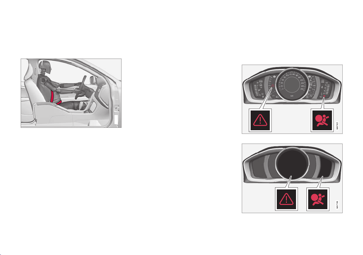
Supplemental Restraint System (SRS)
As an enhancement to the three-point seat
belts (p. 28), your Volvo is equipped with a
Supplemental Restraint System (SRS).
Models with an analog instrument panel
Models with an digital instrument panel*
Page 34

||
SAFETY
32
Volvo's SRS consists of seat belt pretensioners,
front airbags (p. 33), side impact airbags (p. 39), a front passenger occupant
weight sensor (p. 36), and inflatable curtains (p. 41). All of these systems are monitored by the SRS control module. An SRS warning light in the instrument panel (see the illustration) illuminates when the ignition is in modes I
or II, and will normally go out after approximately
6 seconds if no faults are detected in the system.
Where applicable, a text message will also be
displayed when the SRS warning light illuminates.
If this warning symbol is not functioning properly,
the general warning symbol illuminates and a text
message will be displayed.
See also Information displays – indicator symbols
(p. 67) and Information displays – warning symbols (p. 69) for more information about indicator and warning lights.
WARNING
•
If the SRS warning light stays on after the
engine has started or if it illuminates
while you are driving, have the vehicle
inspected by a trained and qualified Volvo
service technician as soon as possible.
•
Never try to repair any component or part
of the SRS yourself. Any interference in
the system could cause malfunction and
serious injury. All work on these systems
should be performed by a trained and
qualified Volvo service technician.
WARNING
If your vehicle has become flood-damaged in
any way (e.g., soaked carpeting/standing
water on the floor of the vehicle), do not
attempt to start the vehicle or insert the
remote key into the ignition slot before disconnecting the battery (see below). This may
cause airbag deployment which could result in
serious injury. Have the vehicle towed to a
trained and qualified Volvo service technician
for repairs.
Before attempting to tow the vehicle:
1. Switch off the ignition for at least
10 minutes and disconnect the battery.
2. Follow the instructions for manually overriding the shiftlock system Transmission –
shiftlock override (p. 259).
Related information
•
Crash mode – general information (p. 44)
Page 35

SAFETY
}}
33
Front airbags
The front airbags supplement the three-point
seat belts (p. 28). For these airbags to provide
the protection intended, seat belts must be worn
at all times.
G018665
The front airbag system
The front airbag system includes gas generators
surrounded by the airbags, and deceleration sensors that activate the gas generators, causing the
airbags to be inflated with nitrogen gas.
Location of the passenger's side front airbag
As the movement of the seats' occupants compresses the airbags, some of the gas is expelled
at a controlled rate to provide better cushioning.
Both seat belt pretensioners also deploy, minimizing seat belt slack. The entire process, including inflation and deflation of the airbags, takes
approximately one fifth of a second.
The location of the front airbags is indicated by
SRS AIRBAG embossed on the steering wheel
pad and above the glove compartment, and by
decals on both sun visors and on the front and
far right side of the dash.
The driver's side front airbag is folded and
located in the steering wheel hub.
The passenger's side front airbag is folded
behind a panel located above the glove compartment.
WARNING
•
The airbags in the vehicle are designed to
be a SUPPLEMENT to–not a replacement for–the three-point seat belts. For
maximum protection, wear seat belts at all
times. Be aware that no system can prevent all possible injuries that may occur in
an accident.
•
Never drive with your hands on the steering wheel pad/airbag housing.
•
The front airbags are designed to help
prevent serious injury. Deployment occurs
very quickly and with considerable force.
During normal deployment and depending on variables such as seating position,
one may experience abrasions, bruises,
swellings, or other injuries as a result
from deployment of one or both of the
airbags.
•
When installing any accessory equipment,
make sure that the front airbag system is
not damaged. Any interference in the system could cause malfunction.
Front airbag deployment
•
The front airbags are designed to deploy during certain frontal or front-angular collisions,
impacts, or decelerations, depending on the
crash severity, angle, speed and object
impacted. The airbags may also deploy in
Page 36

||
SAFETY
34
certain non-frontal collisions where rapid
deceleration occurs.
•
The SRS (p. 31) sensors, which trigger the
front airbags, are designed to react to both
the impact of the collision and the inertial
forces generated by it, and to determine if
the intensity of the collision is sufficient for
the seat belt pretensioners and/or airbags to
be deployed.
However, not all frontal collisions activate the
front airbags.
•
If the collision involves a nonrigid object (e.g.,
a snow drift or bush), or a rigid, fixed object
at a low speed, the front airbags will not necessarily deploy.
•
Front airbags do not normally deploy in a
side impact collision, in a collision from the
rear or in a rollover situation.
•
The amount of damage to the bodywork
does not reliably indicate if the airbags
should have deployed or not.
WARNING
If any of the airbags have deployed:
•
Do not attempt to drive the vehicle. Have
it towed to a qualified repair facility.
•
If necessary seek medical attentIon.
WARNING
•
Do not use child safety seats or child
booster cushions/backrests in the front
passenger's seat. We also recommend
that occupants under 4 feet 7 inches
(140 cm) in height who have outgrown
these devices sit in the rear seat with the
seat belt fastened1.
•
Never drive with the airbags deployed.
The fact that they hang out can impair the
steering of your vehicle. Other safety systems can also be damaged.
•
The smoke and dust formed when the
airbags are deployed can cause skin and
eye irritation in the event of prolonged
exposure.
Should you have questions about any component
in the SRS system, please contact a trained and
qualified Volvo service technician or Volvo customer support:
In the USA
Volvo Car USA, LLC
Customer Care Center
1 Volvo Drive
P.O. Box 914
Rockleigh, New Jersey 07647
1-800-458-1552
www.volvocars.com/us
In Canada
Volvo Car Canada Ltd.
Customer Care Centre
9130 Leslie Street, Suite 101
Richmond Hill, Ontario L4B 0B9
1-800-663-8255
www.volvocars.com/ca
1
See also the Occupant Weight Sensor information, (p. 36).
Page 37
SAFETY
}}
35
NOTE
•
Deployment of front airbags occurs only
one time during an accident. In a collision
where deployment occurs, the airbags
and seat belt pretensioners activate.
Some noise occurs and a small amount
of powder is released. The release of the
powder may appear as smoke-like matter.
This is a normal characteristic and does
not indicate fire.
•
Volvo's front airbags use special sensors
that are integrated with the front seat
buckles. The point at which the airbag
deploys is determined by whether or not
the seat belt is being used, as well as the
severity of the collision.
•
Collisions can occur where only one of
the airbags deploys. If the impact is less
severe, but severe enough to present a
clear injury risk, the airbags are triggered
at partial capacity. If the impact is more
severe, the airbags are triggered at full
capacity.
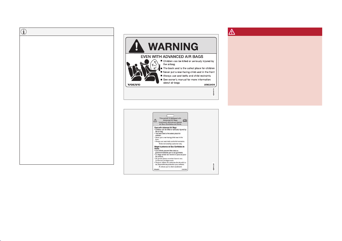
Airbag decals
Airbag decal on the outside of both sun visors
Passenger's side airbag decal
WARNING
•
Children must never be allowed in the
front passenger's seat.
•
Occupants in the front passenger's seat
must never sit on the edge of the seat, sit
leaning toward the instrument panel or
otherwise sit out of position.
•
The occupant's back must be as upright
as comfort allows and be against the seat
back with the seat belt properly fastened.
•
Feet must be on the floor, e.g., not on the
dash, seat or out of the window.
Page 38

||
SAFETY
36
WARNING
•
No objects or accessory equipment, e.g.
dashboard covers, may be placed on,
attached to, or installed near the air bag
hatch (the area above the glove compartment) or the area affected by airbag
deployment.
•
There should be no loose articles, such
as coffee cups on the floor, seat, or dashboard area.
•
Never try to open the airbag cover on the
steering wheel or the passenger's side
dashboard. This should only be done by a
trained and qualified Volvo service technician.
•
Failure to follow these instructions can
result in injury to the vehicle occupants.
Related information
•
Occupant Weight Sensor (p. 36)
•
Side impact protection (SIPS) airbags
(p. 39)
•
Inflatable Curtain (IC) (p. 41)
•
Supplemental Restraint System (SRS)
(p. 31)
Occupant Weight Sensor
The Occupant Weight Sensor (OWS) is
designed to meet the regulatory requirements of
Federal Motor Vehicle Safety Standard (FMVSS)
208 and is designed to disable (will not inflate)
the passenger's side front airbag under certain
conditions.
2
2
G017724
Occupant Weight Sensor (OWS) indicator light
Disabling the passenger's side front airbag
Volvo recommends that ALL occupants (adults
and children) shorter than 4 feet 7 inches
(140 cm) be seated in the back seat of any vehicle with a front passenger side airbag (p. 33), and
be properly restrained for their size and weight.
For child safety recommendations, see Child
safety (p. 46).
The OWS works with sensors that are part of the
front passenger's seat and seat belt (p. 28). The
sensors are designed to detect the presence of a
properly seated occupant and determine if the
passenger's side front airbag should be enabled
(may inflate) or disabled (will not inflate).
The OWS will disable (will not inflate) the passenger's side front airbag when:
•
the front passenger's seat is unoccupied, or
has small/medium objects in the front seat,
•
the system determines that an infant is present in a rear-facing infant seat that is installed according to the manufacturer's instructions,
•
the system determines that a small child is
present in a forward-facing child restraint
that is installed according to the manufacturer's instructions,
•
the system determines that a small child is
present in a booster seat,
•
a front passenger takes his/her weight off of
the seat for a period of time,
•
a child or a small person occupies the front
passenger's seat.
The OWS uses a PASSENGER AIRBAG OFF
indicator lamp which will illuminate and stay on to
remind you that the passenger's side front airbag
is disabled. The PASSENGER AIRBAG OFF indicator lamp is located in the overhead console,
near the base of the rearview mirror.
Page 39

SAFETY
}}
37
NOTE
When the ignition is switched on, the OWS
indicator light will illuminate for several seconds while the system performs a self-diagnostic test.
However, if a fault is detected in the system:
•
The OWS indicator light will stay on
•
The SRS warning light (p. 31) will come on
and stay on
•
The message
Pass. Airbag OFF Service
urgent will be displayed in the information
display.
WARNING
If a fault in the system is detected and indicated as described, be aware that the passenger's side front airbag will not deploy in
the event of a collision. In this case, the SRS
system and Occupant Weight Sensor should
be inspected by a trained and qualified Volvo
service technician as soon as possible.
WARNING
•
Never try to open, remove, or repair any
components in the OWS system. This
could result in system malfunction. Maintenance or repairs should only be carried
out by an a trained and qualified Volvo
service technician.
•
The front passenger's seat should not be
modified in any way. This could reduce
pressure on the seat cushion, which
might interfere with the OWS system's
function.
Passenger's
seat occupancy status
OWS indicator light
status
Passenger's
side front airbag status
Seat unoccupied
OWS indicator light
lights up.
Passenger's
side front airbag disabled
Seat occupied by low
weight occupant/object
A
OWS indicator light
lights up
Passenger's
side front airbag disabled
Seat occupied by heavy
occupant/
object
OWS indicator light is
not lit
Passenger's
side front airbag enabled
A
Volvo recommends that children always be properly restrained
in appropriate child restraints in the rear seats. Do not assume
that the passenger's side front airbag is disabled unless the
PASSENGER AIRBAG OFF indicator lamp is lit. Make sure the
child restraint is properly installed. If there is any doubt as to the
status of the passenger's side front airbag, move the child
restraint to the rear seat.
The OWS is designed to enable (may inflate) the
passenger's side front airbag in the event of a
collision anytime the system senses that a person of adult size is sitting properly in the front
passenger's seat. The PASSENGER AIRBAG
OFF indicator lamp will be off and remain off.
If a person of adult size is sitting in the front passenger's seat, but the PASSENGER AIRBAG
OFF indicator lamp is on, it is possible that the
Page 40

||
SAFETY
38
person isn't sitting properly in the seat. If this
happens:
•
Turn the vehicle off and ask the person to
place the seatback in an upright position.
•
Have the person sit upright in the seat, centered on the seat cushion, with the person's
legs comfortably extended.
•
Restart the vehicle and have the person
remain in this position for about two minutes.
This will allow the system to detect that person and enable the passenger's frontal airbag.
•
If the PASSENGER AIRBAG OFF indicator
lamp remains on even after this, the person
should be advised to ride in the rear seat.
This condition reflects limitations of the OWS
classification capability. It does not indicate OWS
malfunction.
Modifications
If you are considering modifying your vehicle in
any way to accommodate a disability, for example
by altering or adapting the driver's or front passenger's seat(s) and/or airbag systems, please
contact Volvo at:
In the USA
Volvo Car USA, LLC
Customer Care Center
1 Volvo Drive
P.O. Box 914
Rockleigh, New Jersey 07647
1-800-458-1552
In Canada
Volvo Car Canada Ltd.
Customer Care Centre
9130 Leslie Street, Suite 101
Richmond Hill, Ontario L4B 0B9
1-800-663-8255
WARNING
•
No objects that add to the total weight on
the seat should be placed on the front
passenger's seat. If a child is seated in
the front passenger's seat with any additional weight, this extra weight could
cause the OWS system to enable the airbag, which might cause it to deploy in the
event of a collision, thereby injuring the
child.
•
The seat belt should never be wrapped
around an object on the front passenger's seat. This could interfere with the
OWS system's function.
•
The front passenger's seat belt should
never be used in a way that exerts more
pressure on the passenger than normal.
This could increase the pressure exerted
on the weight sensor by a child, and
could result in the airbag being enabled,
which might cause it to deploy in the
event of a collision, thereby injuring the
child.
Page 41

SAFETY
}}
39
WARNING
•
Keep the following points in mind with
respect to the OWS system. Failure to
follow these instructions could adversely
affect the system's function and result in
serious injury to the occupant of the front
passenger's seat:
•
The full weight of the front seat passenger should always be on the seat cushion.
The passenger should never lift him/
herself off the seat cushion using the
armrest in the door or the center console,
by pressing the feet on the floor, by sitting on the edge of the seat cushion, or
by pressing against the backrest in a way
that reduces pressure on the seat cushion. This could cause OWS to disable the
front, passenger's side airbag.
WARNING
•
Do not place any type of object on the
front passenger's seat in such a way that
jamming, pressing, or squeezing occurs
between the object and the front seat,
other than as a direct result of the correct
use of the Automatic Locking Retractor/
Emergency Locking Retractor (ALR/ELR)
seat belt (Child restraints (p. 47)).
•
No objects should be placed under the
front passenger's seat. This could interfere with the OWS system's function.
Related information
•
Supplemental Restraint System (SRS)
(p. 31)
Side impact protection (SIPS) airbags
As an enhancement to the structural side impact
protection built into your vehicle, it is also equipped with Side Impact Protection System (SIPS)
airbags.
G032949
Location of the side impact (SIPS) airbags (front seats
only)
The SIPS airbag system is designed to help
increase occupant protection in the event of certain side impact collisions. The SIPS airbags are
designed to deploy only during certain sideimpact collisions, depending on the crash
severity, angle, speed and point of impact.
Page 42

||
SAFETY
40
Driver's side SIPS airbag
Passenger's side SIPS airbag
NOTE
SIPS airbag deployment (one airbag) occurs
only on the side of the vehicle affected by the
impact. The airbags are not designed to
deploy in all side impact situations.
Components in the SIPS airbag system
This SIPS airbag system consists of a gas generator, the side airbag modules built into the outboard sides of both front seat backrests, and
electronic sensors/wiring.
WARNING
•
The SIPS airbag system is a supplement
to the structural Side Impact Protection
System and the three-point seat belt system. It is not designed to deploy during
collisions from the front or rear of the
vehicle or in rollover situations.
•
The use of seat covers on the front seats
may impede SIPS airbag deployment.
•
No objects, accessory equipment or stickers may be placed on, attached to or
installed near the SIPS airbag system or
in the area affected by SIPS airbag
deployment.
•
Never try to open or repair any components of the SIPS airbag system. This
should be done only by a trained and
qualified Volvo service technician.
•
In order for the SIPS airbag to provide its
best protection, both front seat occupants
should sit in an upright position with the
seat belt properly fastened.
•
Failure to follow these instructions can
result in injury to the occupants of the
vehicle in the event of an accident.
Page 43

SAFETY
}}
41
Related information
•
Supplemental Restraint System (SRS)
(p. 31)
•
Front airbags (p. 33)
•
Inflatable Curtain (IC) (p. 41)
Inflatable Curtain (IC)
The inflatable curtain is designed to help protect
the heads of the occupants of the front seats
and the occupant of the outboard rear seating
positions in certain side impact collisions.
This system consists of inflatable curtains located
along the sides of the roof liners, stretching from
the center of both front side windows to the rear
edge of the rear side door windows.
In certain side impacts, both the Inflatable Curtain (IC) and the Side Impact Airbag System (p. 39) (SIPS airbag) will deploy. The IC and
the SIPS airbag deploy simultaneously.
NOTE
If the inflatable curtain deploys, it remains
inflated for approximately 6 seconds.
WARNING
•
The IC system is a supplement to the
Side Impact Protection System. It is not
designed to deploy during collisions from
the rear of the vehicle.
•
Never try to open or repair any components of the IC system. This should be
done only by a trained and qualified Volvo
service technician.
•
Never hang heavy items from the ceiling
handles. This could impede deployment
of the Inflatable Curtain.
•
The rear seat should not be loaded to a
level higher than 2 in. (5 cm) below the
upper edge of the rear side windows.
Objects placed higher than this level
could impede the function of the Inflatable Curtain.
WARNING
In order for the IC to provide its best protection, both front seat occupants and both outboard rear seat occupants should sit in an
upright position with the seat belt properly
fastened; adults using the seat belt and children using the proper child restraint system.
Failure to follow these instructions can result
in injury to the vehicle occupants in an accident.
Page 44

||
SAFETY
42
Related information
•
Supplemental Restraint System (SRS)
(p. 31)
•
Front airbags (p. 33)
•
Child safety (p. 46)
Whiplash Protection System (WHIPS)
The WHIPS system consists of specially
designed hinges and brackets on the front seat
backrests designed to help absorb some of the
energy generated in a collision from the rear
(when the vehicle is rear-ended).
In the event of a rear-end collision, the hinges
and brackets of the front seat backrests are
designed to change position slightly to allow the
Page 45

SAFETY
}}
43
backrest/head restraint to help support the occupant's head before moving slightly rearward. This
movement helps absorb some of the forces that
could result in whiplash.
WARNING
•
The WHIPS system is designed to supplement the other safety systems in your
vehicle. For this system to function properly, the three-point seat belt must be
worn. Please be aware that no system
can prevent all possible injuries that may
occur in an accident.
•
The WHIPS system is designed to function in certain collisions from the rear,
depending on the crash severity, angle
and speed.
WARNING
•
Occupants in the front seats must never
sit out of position. The occupant's back
must be as upright as comfort allows and
be against the seat back with the seat
belt properly fastened.
•
If your vehicle has been involved in a rearend collision, the front seat backrests
must be inspected by a trained and qualified Volvo service technician, even if the
seats appear to be undamaged. Certain
components in the WHIPS system may
need to be replaced.
•
Do not attempt to service any component
in the WHIPS system yourself.
WARNING
•
Boxes, suitcases, etc. wedged behind the
front seats could impede the function of
the Whiplash Protection System.
•
If the rear seat backrests are folded
down, cargo must be secured to prevent
it from sliding forward against the front
seat backrests in the event of a collision
from the rear. This could interfere with
the action of the Whiplash Protection
System.
Page 46

||
SAFETY
* Option/accessory.
44
WARNING
Any contact between the front seat backrests
and the folded rear seat or a rear-facing child
seat could impede the function of the WHIPS
system. If the rear seat is folded down, the
occupied front seats must be adjusted forward so that they do not touch the folded rear
seat.
Related information
•
Seat belts – general (p. 28)
Crash mode – general information
After a collision, the functionality of some of the
vehicle's systems may be reduced as a safety
precaution.
Warning symbol: analog instrument panel
Warning symbol: digital instrument panel*
If the vehicle has been involved in a collision, the
text
Safety mode See manual may appear in
the information display.
NOTE
This text can only be shown if the display is
undamaged and the vehicle's electrical system is intact.
Crash mode is a feature that is triggered if one or
more of the safety systems (e.g. front (p. 33) or
side airbags (p. 39), an inflatable curtain (p. 41),
or one or more of the seat belt pretensioners)
has deployed. The collision may have damaged
an important function in the vehicle, such as the
fuel lines, sensors for one of the safety systems,
the brake system, etc.
Page 47

SAFETY
45
WARNING
•
Never attempt to repair the vehicle yourself or to reset the electrical system after
the vehicle has displayed
Safety mode
See manual. This could result in injury or
improper system function.
•
Restoring the vehicle to normal operating
status should only be done by a trained
and qualified Volvo service technician.
•
After
Safety mode See manual has
been displayed, if you detect the odor of
fuel vapor, or see any signs of fuel leakage, do not attempt to start the vehicle.
Leave the vehicle immediately.
Related information
•
Crash mode – starting the vehicle (p. 45)
•
Crash mode – moving the vehicle (p. 45)
Crash mode – starting the vehicle
If Crash mode has been set Crash
mode (p. 44)) and damage to the vehicle is
minor and there is no fuel leakage, you may
attempt to start the engine.
To do so:
1. Remove the remote key from the ignition slot
and open the driver's door. If a message is
displayed that the ignition is on, press the
start button.
2. Close the driver's door and reinsert the
remote key in the ignition slot.
3. Try to start the vehicle.
WARNING
If the message Safety mode See manual is
still displayed, the vehicle should not be driven
and must be towed. Concealed faults may
make the vehicle difficult to control.
Related information
•
Crash mode – general information (p. 44)
•
Crash mode – moving the vehicle (p. 45)
Crash mode – moving the vehicle
If the message
Normal mode appears after an
attempt has been made to start the engine, Starting the vehicle after a crash (p. 45), the vehicle
may be moved carefully from its present position,
if for example, it is blocking traffic. It should,
however, not be moved farther than is absolutely
necessary.
WARNING
Even if the vehicle appears to be drivable after
Crash mode has been set, it should not be
driven or towed (pulled by another vehicle).
There may be concealed damage that could
make it difficult or impossible to control. The
vehicle should be transported on a flatbed
tow truck to a trained and qualified Volvo
service technician for inspection/repairs.
Related information
•
Crash mode – general information (p. 44)
Page 48

SAFETY
46
Child safety
Children should always be seated safely when
traveling in the vehicle.
General information
Volvo recommends the proper use of restraint
systems (p. 47) for all occupants including children. Remember that, regardless of age and size,
a child should always be properly restrained in a
vehicle.
Your vehicle is also equipped with ISOFIX/
LATCH attachments (p. 55), which make it
more convenient to install child seats.
Some restraint systems for children are designed
to be secured in the vehicle by lap belts or the
lap portion of a lap-shoulder belt. Such child
restraint systems can help protect children in
vehicles in the event of an accident only if they
are used properly. However, children could be
endangered in a crash if the child restraints are
not properly secured in the vehicle. Failure to follow the installation instructions for your child
restraint can result in your child striking the vehicle's interior in a sudden stop.
Holding a child in your arms is NOT a suitable
substitute for a child restraint system. In an accident, a child held in a person's arms can be
crushed between the vehicle's interior and an
unrestrained person. The child could also be
injured by striking the interior, or by being ejected
from the vehicle during a sudden maneuver or
impact. The same can also happen if the infant or
child rides unrestrained on the seat. Other occupants should also be properly restrained to help
reduce the chance of injuring or increasing the
injury of a child.
All states and provinces have legislation governing how and where children should be carried in
a vehicle. Find out the regulations existing in your
state or province. Recent accident statistics have
shown that children are safer in rear seating
positions than front seating positions when properly restrained. A child restraint system can help
protect a child in a vehicle. Here's what to look
for when selecting a child restraint system:
It should have a label certifying that it meets
applicable Federal Motor Vehicle Safety Standards (FMVSS 213) – or in Canada, CMVSS 213.
Make sure the child restraint system is approved
for the child's height, weight and development –
the label required by the standard or regulation,
or instructions for infant restraints, typically provide this information.
In using any child restraint system, we urge you
to carefully look over the instructions that are
provided with the restraint. Be sure you understand them and can use the device properly and
safely in this vehicle. A misused child restraint
system can result in increased injuries for both
the infant or child and other occupants in the
vehicle.
When a child has outgrown the child safety seat,
you should use the rear seat with the standard
seat belt fastened. The best way to help protect
the child here is to place the child on a cushion
so that the seat belt is properly located on the
hips (see Booster cushions (p. 54) for illustration). Legislation in your state or province may
mandate the use of a child seat or cushion in
combination with the seat belt, depending on the
child's age and/or size. Please check local regulations.
A specially designed and tested booster cushion
and backrest can be obtained from your Volvo
retailer. See also Booster cushions (p. 54)
Page 49

SAFETY
}}
47
WARNING
•
Do not use child safety seats or child
booster cushions/backrests in the front
passenger's seat. We also recommend
that children under 4 feet 7 inches
(140 cm) in height who have outgrown
these devices sit in the rear seat with the
seat belt fastened.
•
Sedan models: Keep vehicle doors and
trunk locked and keep remote controls
out of a child’s reach. Unsupervised children could lock themselves in an open
trunk and risk injury. Children should be
taught not to play in vehicles.
•
On hot days, the temperature in the vehicle interior can rise very quickly. Exposure
to these high temperatures for even a
short period of time can cause heat-related injury or death. Small children are particularly at risk.
Child seat should always be registered. See Child
restraints (p. 47) for more information.
Volvo's recommendations
Why does Volvo believe that no child should sit in
the front seat of a car? It's quite simple really. A
front airbag (p. 33) is a very powerful device
designed, by law, to help protect an adult.
Because of the size of the airbag and its speed
of inflation, a child should never be placed in the
front seat, even if he or she is properly belted or
strapped into a child safety seat. Volvo has been
an innovator in safety for over seventy-five years,
and we'll continue to do our part. But we need
your help. Please remember to put your children
in the back seat, and buckle them up.
Volvo has some very specific recommendations:
•
Always wear your seat belt (p. 28).
•
Airbags are a SUPPLEMENTAL safety
device which, when used with a three-point
seat belt can help reduce serious injuries
during certain types of accidents. Volvo recommends that you do not disconnect the airbag system in your vehicle.
•
Volvo strongly recommends that everyone in
the vehicle be properly restrained.
•
Volvo recommends that ALL occupants
(adults and children) shorter than 4 feet
7 inches (140 cm) be seated in the back
seat of any vehicle with a front passenger
side airbag.
•
Drive safely!
Related information
•
Infant seats (p. 49)
•
Convertible seats (p. 52)
•
Booster cushions (p. 54)
•
Child safety locks (p. 58)
•
Top tether anchors (p. 56)
Child restraints
Suitable child restraints should always be used
when children travel in the vehicle.
Child restraint systems
G022840
Infant seat
There are three main types of child restraint systems: infant seats (p. 49), convertible
seats (p. 52), and booster cushions (p. 54).
They are classified according to the child's age
and size.
The following section provides general informa-
tion on securing a child restraint using a threepoint seat belt (p. 28). Refer to ISOFIX/LATCH
lower anchors (p. 55) and Top tether anchors
(p. 56) for information on securing a child
restraint using ISOFIX/LATCH lower anchors
and/or top tether anchorages.
Page 50

||
SAFETY
48
G022847
Convertible seat
WARNING
A child seat should never be used in the front
passenger seat of any vehicle with a front
passenger airbag – not even if the "Passenger airbag off" symbol near the rear-view mirror is illuminated (on vehicles equipped with
Occupant Weight Sensor). If the severity of an
accident were to cause the airbag to inflate,
this could lead to serious injury or death to a
child seated in this position.
G023269
Booster cushion
WARNING
Always refer to the child restraint manufacturer's instructions for detailed information on
securing the restraint.
WARNING
•
When not in use, keep the child restraint
system secured or remove it from the
passenger compartment to help prevent it
from injuring passengers in the event of a
sudden stop or collision.
•
A small child's head represents a considerable part of its total weight and its neck
is still very weak. Volvo recommends that
children up to age 4 travel, properly
restrained, facing rearward. In addition,
Volvo recommends that children should
ride rearward facing, properly restrained,
as long as possible.
Automatic Locking Retractor/ Emergency Locking Retractor (ALR/ ELR)
To make child seat installation easier, each seat
belt (except for the driver's belt) is equipped with
a locking mechanism to help keep the seat belt
taut.
Page 51

SAFETY
}}
49
When attaching the seat belt to a child seat:
1. Attach the seat belt to the child seat according to the child seat manufacturer's instructions.
2. Pull the seat belt out as far as possible.
3. Insert the seat belt latch plate into the buckle
(lock) in the usual way.
4. Release the seat belt and pull it taut around
the child seat.
A sound from the seat belt retractor will be audible at this time and is normal. The belt will now
be locked in place. This function is automatically
disabled when the seat belt is unlocked and the
belt is fully retracted.
WARNING
Do not use child safety seats or child booster
cushions/backrests in the front passenger's
seat. We also recommend that children who
have outgrown these devices sit in the rear
seat with the seat belt properly fastened.
Child restraint registration and recalls
Child restraints could be recalled for safety reasons. You must register your child restraint to be
reached in a recall. To stay informed about child
safety seat recalls, be sure to fill out and return
the registration card that comes with new child
restraints.
Child restraint recall information is readily available in both the U.S. and Canada. For recall information in the U.S., call the U.S. Government's
Auto Safety Hotline at 1-800-424-9393 or go to
http://www-odi.nhtsa.dot.gov/cars/problems/
recalls/register/childseat/index.cfm. In Canada,
visit Transport Canada's Child Safety website at
http://www.tc.gc.ca/roadsafety/childsafety/
menu.htm.
Related information
•
Child safety locks (p. 58)
Infant seats
Suitable child restraints should always be used
when children (depending on their age/size) are
seated in the vehicle.
Securing an infant seat with a seat belt
G022844
Do not place the infant seat in the front passenger's
seat
NOTE
Refer to (p. 55) and (p. 56) for information on securing a child restraint using ISOFIX/LATCH lower anchors and/or top tether
anchorages.
1. Place the infant seat in the rear seat of the
vehicle.
Page 52
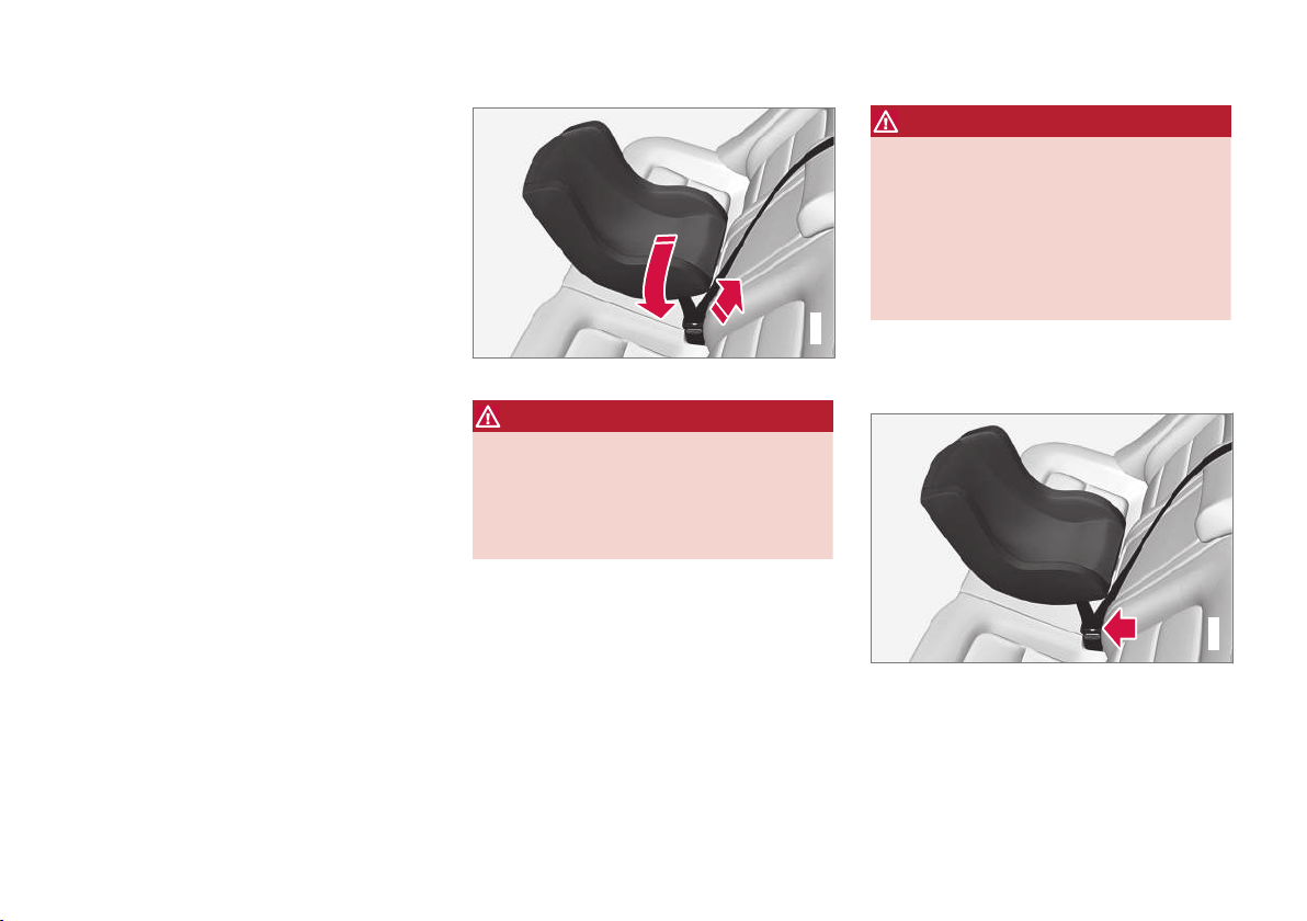
||
SAFETY
50
2. Attach the seat belt to the infant seat
according to the manufacturer's instructions.
G023270
Positioning the seat belt through the infant seat
WARNING
•
An infant seat must be in the rear-facing
position only.
•
The infant seat should not be positioned
behind the driver's seat unless there is
adequate space for safe installation.
WARNING
A child seat should never be used in the front
passenger seat of any vehicle with a front
passenger airbag – not even if the "Passenger airbag off" symbol near the rear-view mirror is illuminated (on vehicles equipped with
Occupant Weight Sensor). If the severity of an
accident were to cause the airbag to inflate,
this could lead to serious injury or death to a
child seated in this position.
3. Fasten the seat belt by inserting the latch
plate into the buckle (lock) until a distinct
click is audible.
G023271
Fasten the seat belt
Page 53

SAFETY
51
G022846
Pull out the shoulder section of the seat belt
4. Pull the shoulder section of the seat belt out
as far as possible to activate the belt's automatic locking function.
NOTE
The locking retractor will automatically
release when the seat belt is unbuckled and
allowed to retract fully.
5. Press the infant seat firmly in place, let the
seat belt retract and pull it taut. A sound from
the seat belt retractor's automatic locking
function will be audible at this time and is
normal. The seat belt should now be locked
in place.
G022850
Ensure that the seat is securely in place
6. Push and pull the infant seat along the seat
belt path to ensure that it is held securely in
place by the seat belt.
WARNING
It should not be possible to move the child
restraint (child seat) more than 1 in. (2.5 cm)
in any direction along the seat belt path.
The infant seat can be removed by unbuckling
the seat belt and letting it retract completely.
Related information
•
Child safety (p. 46)
•
Child restraints (p. 47)
•
Convertible seats (p. 52)
•
ISOFIX/LATCH lower anchors (p. 55)
•
Top tether anchors (p. 56)
Page 54

SAFETY
52
Convertible seats
Suitable child restraints should always be used
when children (depending on their age/size) are
seated in the vehicle.
Securing a convertible seat with a seat belt
G018630
Do not place the convertible seat in the front passenger's seat
NOTE
Refer to (p. 55) and (p. 56) for information
on securing a child restraint using ISOFIX/
LATCH lower anchors and/or top tether
anchorages.
Convertible seats can be used in either a forward
or rearward-facing position, depending on the
age and size of the child.
G022847
Route the seat belt through the convertible seat
WARNING
Always use a convertible seat that is suitable
for the child's age and size. See the convertible seat manufacturer's recommendations.
1. Place the convertible seat in the rear seat of
the vehicle.
WARNING
•
A small child's head represents a considerable part of its total weight and its neck is
still very weak. Volvo recommends that
children up to age 4 travel, properly
restrained, facing rearward. In addition,
Volvo recommends that children should
ride rearward facing, properly restrained, as
long as possible.
•
Convertible child seats should be installed
in the rear seat only.
•
A rear-facing convertible seat should not
be positioned behind the driver's seat
unless there is adequate space for safe
installation.
2. Attach the seat belt to the convertible seat
according to the manufacturer's instructions.
Page 55

SAFETY
}}
53
G022848
Fasten the seat belt
3. Fasten the seat belt by inserting the latch
plate into the buckle (lock) until a distinct
click is audible.
4. Pull the shoulder section of the seat belt out
as far as possible to activate the belt's automatic locking function.
NOTE
The locking retractor will automatically
release when the seat belt is unbuckled and
allowed to retract fully.
5. Press the convertible seat firmly in place, let
the seat belt retract and pull it taut. A sound
from the seat belt retractor's automatic locking function will be audible at this time and is
normal. The seat belt should now be locked
in place.
G022849
Pull out the shoulder section of the seat belt
6. Push and pull the convertible seat along the
seat belt path to ensure that it is held
securely in place by the seat belt.
WARNING
It should not be possible to move the child
restraint (child seat) more than 1 in. (2.5 cm)
in any direction along the seat belt path.
The convertible seat can be removed by unbuckling the seat belt and letting it retract completely.
G022850
Ensure that the seat is securely in place
WARNING
A child seat should never be used in the front
passenger seat of any vehicle with a front
passenger airbag – not even if the "Passenger airbag off" symbol near the rear-view mirror is illuminated. If the severity of an accident
were to cause the airbag to inflate, this could
lead to serious injury or death to a child
seated in this position.
Page 56

||
SAFETY
54
Related information
•
Child safety (p. 46)
•
Child restraints (p. 47)
•
Infant seats (p. 49)
•
ISOFIX/LATCH lower anchors (p. 55)
•
Top tether anchors (p. 56)
Booster cushions
Booster cushions should be properly positioned
in the vehicle.
Securing a booster cushion
G022851
Position the child correctly on the booster cushion
Booster cushions are recommended for children
who have outgrown convertible seats (p. 52).
1. Place the booster cushion in the rear seat of
the vehicle.
2. With the child properly seated on the booster
cushion, attach the seat belt to or around the
cushion according to the manufacturer's
instructions.
3. Fasten the seat belt by inserting the latch
plate into the buckle (lock) until a distinct
click is audible.
G022852
Positioning the seat belt
4. Ensure that the seat belt is pulled taut and
fits snugly around the child.
WARNING
•
The hip section of the three-point seat
belt must fit snugly across the child's
hips, not across the stomach.
•
The shoulder section of the three-point
seat belt should be positioned across the
chest and shoulder.
•
The shoulder belt must never be placed
behind the child's back or under the arm.
Page 57

SAFETY
}}
55
Related information
•
Child safety (p. 46)
•
Child restraints (p. 47)
•
Infant seats (p. 49)
•
Convertible seats (p. 52)
•
ISOFIX/LATCH lower anchors (p. 55)
•
Top tether anchors (p. 56)
ISOFIX/LATCH lower anchors
Lower anchors for ISOFIX/LATCH-equipped
child seats are located in the rear, outboard
seats, hidden below the backrest cushions.
Using the ISOFIX/LATCH lower child seat anchors
Symbols on the seat back upholstery mark the
ISOFIX/LATCH anchor positions as shown. To
access the anchors, kneel on the seat cushion
and locate the anchors by feel. Always follow your
child seat manufacturer's installation instructions,
and use both ISOFIX/LATCH lower anchors and
top tethers (p. 56) whenever possible.
To access the anchors
1. Put the child restraint in position.
2. Kneel on the child restraint to press down
the seat cushion and locate the anchors by
feel.
3. Fasten the attachment on the child
restraint's lower straps to the ISOFIX/
LATCH/LATCH lower anchors.
4. Firmly tension the lower child seat straps
according to the manufacturer's instructions.
WARNING
Volvo's ISOFIX/LATCH anchors conform to
FMVSS/CMVSS standards. Always refer to
the child restraint system's manual for weight
and size ratings.
NOTE
•
The rear seat's center position is not
equipped with ISOFIX/LATCH lower
anchors. When installing a child restraint
in this position, attach the restraint's top
tether strap (if it is so equipped) to the
top tether anchorage point and secure
the restraint with the vehicle's center seat
belt.
•
Always follow your child seat manufacturer's installation instructions, and use both
ISOFIX/LATCH lower anchors and top
tethers whenever possible.
Page 58

||
SAFETY
56
G018631
Fasten the attachment correctly to the ISOFIX/LATCH
lower anchors
WARNING
•
Be sure to fasten the attachment correctly to the anchor (see the illustration).
If the attachment is not correctly fastened, the child restraint may not be
properly secured in the event of a collision.
•
The ISOFIX/LATCH lower child restraint
anchors are only intended for use with
child seats positioned in the outboard
seating positions. These anchors are not
certified for use with any child restraint
that is positioned in the center seating
position. When securing a child restraint
in the center seating position, use only
the vehicle's center seat belt.
Related information
•
Child safety (p. 46)
•
Infant seats (p. 49)
•
Convertible seats (p. 52)
Top tether anchors
Your Volvo is equipped with child restraint top
tether anchorages in the rear seat. They are
located on the rear parcel shelf.
Child restraint anchorages
Page 59

SAFETY
57
Securing a child seat
1. Place the child restraint on the rear seat.
2. Fold up the plastic cover over the anchorage
to be used.
3. Route the top tether strap under the head
restraint and attach it to the anchor.
4. Fold down the outboard head restraints or
lower the center head restraint for easier
access to the ISOFIX/LATCH anchor.
5. Attach lower tether straps to the lower ISOFIX/LATCH anchors. If the child restraint is
not equipped with lower tether straps, or the
restraint is used in the center seating position, follow instructions for securing a child
restraint using the Automatic Locking
Retractor seat belt (see Child restraints
(p. 47)).
6. Firmly tension all straps.
Refer also to the child seat manufacturer's
instructions for information on securing the child
seat.
WARNING
•
Always refer to the recommendations
made by the child restraint manufacturer.
•
Volvo recommends that the top tether
anchors be used when installing a forward-facing child restraint.
•
Never route a top tether strap over the
top of the head restraint. The strap
should be routed beneath the head
restraint.
•
Child restraint anchorages are designed
to withstand only those loads imposed by
correctly fitted child restraints. Under no
circumstances are they to be used for
adult seat belts or harnesses. The anchorages are not able to withstand excessive
forces on them in the event of collision if
full harness seat belts or adult seat belts
are installed to them. An adult who uses a
belt anchored in a child restraint anchorage runs a great risk of suffering severe
injuries should a collision occur.
•
Do not install rear speakers that require
the removal of the top tether anchors or
interfere with the proper use of the top
tether strap.
Related information
•
Child safety (p. 46)
•
Infant seats (p. 49)
•
Convertible seats (p. 52)
•
ISOFIX/LATCH lower anchors (p. 55)
Page 60

SAFETY
58
Child safety locks
Child safety locks help prevent children from
inadvertently opening one of the rear doors from
inside the vehicle.
Manual child safety locks
Child safety locks – rear doors
The controls are located on the rear door jambs.
Use the remote control's key blade or a screwdriver to adjust these controls.
The rear doors can only be opened from the
outside when the slot is in the horizontal
position.
The rear doors can be opened from the
inside when the slot is in the vertical position.
Related information
•
Detachable key blade – general information
(p. 149)
•
Locking/unlocking – from inside (p. 158)
Page 61

INSTRUMENTS AND CONTROLS
Page 62

INSTRUMENTS AND CONTROLS
60
Instrument overview
This overview shows the location of the instrument panel and center console displays, and
controls/buttons/switches.
Page 63

INSTRUMENTS AND CONTROLS
}}
61
Page 64

||
INSTRUMENTS AND CONTROLS
* Option/accessory.
62
Function See
Controls for menus and
messages, turn signals,
high/low beams, trip
computer
(p. 71),
(p. 90),
(p. 83),
(p. 110)
Paddles for manually
shifting gears*
(p. 257)
Cruise control (p. 172)
Horn, airbag (p. 82),
(p. 33)
Main instrument panel (p. 63)
Infotainment system/
Bluetooth hands-free
controls
Sensus Infotainment supplement
START/STOP ENGINE
button
(p. 73)
Ignition slot (p. 73)
Display for infotainment
system functions and
menus
(p. 108), Sensus Infotainment supplement
Door handle -
Function See
In-door control panels
(power windows, mirrors, central locking button)
(p. 96),
(p. 97),
(p. 158)
Hazard warning flashers (p. 89)
Controls for the infotainment system and
menus
(p. 71),
(p. 125), Sensus Infotainment supplement
Climate system controls (p. 125)
Gear selector (p. 255)
Not in use -
Wipers and washers (p. 93),
(p. 94)
Steering wheel adjustment
(p. 82)
Hood opening control (p. 327)
Parking brake (p. 271)
Function See
Power seat* adjustment
controls
(p. 76)
Lighting panel, buttons
for opening fuel filler
door and unlocking and
opening the trunk
(p. 83),
(p. 280),
(p. 160)
Related information
•
Information displays – ambient temperature
sensor (p. 72)
•
Information displays – trip odometer and
clock (p. 73)
Page 65

INSTRUMENTS AND CONTROLS
}}
* Option/accessory.
63
Information displays – introduction
The displays show information on some of the
vehicle's functions, such as cruise control, the
trip computer and messages. The information is
shown with text and symbols.
Information displays: analog instrument panel
Information displays: digital instrument panel*
More detailed information can be found in the
descriptions of the functions that use the information displays.
Gauges and indicators: analog instrument panel
Fuel gauge: When the indicator shows one
white marking1, a yellow indicator light will
illuminate to indicate a low fuel level. See
also Trip computer – introduction (p. 110)
and Refueling – fuel requirements (p. 277)
for additional information.
Eco meter: Indicates how economically the
vehicle is being driven. The higher the needle
moves on the scale, the more economically
the vehicle is being driven.
Speedometer
Tachometer: Shows engine speed in thousands of revolutions per minute (rpm)
Gear indicator: Shows the currently selected
gear
1
When the message
Distance to empty fuel tank: shows "----", the marker turns red
Page 66

||
INSTRUMENTS AND CONTROLS
* Option/accessory.
64
Gauges and indicators: digital instrument panel*
Different themes (display alternatives) can be
selected for the digital instrument panel:
•
Elegance
•
Eco
•
Performance
To change themes, press the OK button on the
left steering wheel lever and use the thumb
wheel to scroll to
Themes. Press OK to confirm
your choice.
Theme Elegance: gauges and indicators
Fuel gauge. When the indicator shows one
white marking, a yellow indicator light will illuminate to indicate a low fuel level. See also
Trip computer – introduction (p. 110) and
Refueling – fuel requirements (p. 277) for
additional information.
Coolant temperature gauge
Speedometer
Tachometer (engine speed in thousands of
revolutions per minute (rpm))
Gear indicator: Shows the currently selected
gear
Theme Eco: gauges and indicators
Fuel gauge. When the indicator shows a
white marking, a yellow indicator light will illuminate to indicate a low fuel level. See also
Trip computer – introduction (p. 110) and
Refueling – fuel requirements (p. 277) for
additional information.
Eco Guide (see Eco Guide* and Power
Meter* (p. 66))
Speedometer
Tachometer (engine speed in thousands of
revolutions per minute (rpm))
Gear indicator: Shows the currently selected
gear
Theme Performance: gauges and indicators
Fuel gauge. When the indicator shows a
white marking, a yellow indicator light will illuminate to indicate a low fuel level. See also
Trip computer – introduction (p. 110) and
Refueling – fuel requirements (p. 277) for
additional information.
Coolant temperature gauge
Speedometer
Tachometer (shows engine speed in thousands of revolutions per minute (rpm))
Page 67

INSTRUMENTS AND CONTROLS
* Option/accessory.
65
Power Meter (see Eco Guide* and Power
Meter* (p. 66)).
Gear indicator: Shows the currently selected
gear
Indicator and warning symbols
Indicator and warning symbols: analog instrument panel
Indicator symbols
Indicator and warning symbols
Warning symbols
Indicator and warning symbols: digital instrument panel
Indicator symbols
Indicator and warning symbols
Warning symbols
Function check
All indicator and warning symbols light up in ignition mode II or when the engine is started. When
the engine has started, all the symbols should go
out except the parking brake symbol, which only
goes out when the brake is disengaged.
If the engine does not start or if the function
check is carried out in ignition mode II, all symbols go out after 5 seconds except the malfunction indicator light, which may indicate a fault in
the vehicle's emissions system, and the symbol
for low oil pressure.
Some of the symbols shown may not be available
in all markets or models.
Related information
•
Instrument overview (p. 60)
•
Information displays – indicator symbols
(p. 67)
•
Information displays – warning symbols
(p. 69)
Page 68

INSTRUMENTS AND CONTROLS
* Option/accessory.
66
Eco Guide* and Power Meter*
Eco guide and Power guide are two gauges in
the instrument panel that help improve driving
economy.
The vehicle also stores driving-related statistics
in the form of a bar graph, see Trip computer –
Trip statistics (p. 117).
Introduction
To display or remove these functions from the
instrument panel, select the "Eco" theme (see
Information displays – introduction (p. 63)).
Driving statistics are also stored and can be displayed in the form of a bar chart (see Trip computer – Trip statistics (p. 117)).
Eco Guide
This gauge gives an indication of how economically the vehicle is being driven.
Current (instantaneous) reading
Average
Current (instantaneous) reading
This is the current level of economical driving; the
higher the reading, the more economically the
vehicle is being driven.
This value is calculated based on the vehicle's
speed, engine speed (rpm), engine load and
brake use.
The optimal speed range is between approximately 30–50 mph (50–80 km/h), preferably at
as low rpm as possible. The markers fall when
the brake or accelerator pedal is pressed.
If the current reading is very low, the red field in
the gauge will illuminate after a slight delay, indicating low driving economy.
Average
The average reading changes gradually according to changes in the current reading to indicate
how economically the vehicle has been driven
recently. The higher the average reading, the
more economically the vehicle has been driven.
Power Meter
This gauge indicates the engine power that has
been utilized and the amount of power remaining.
Available power
Utilized power
Available power
The smaller, upper indicator shows the engine's
available power2. The higher the reading on the
scale, the greater the amount of power remaining
in the current gear.
2
Depending on rpm
Page 69

INSTRUMENTS AND CONTROLS
}}
* Option/accessory.
67
Utilized power
The larger, lower indicator shows the amount of
engine power that has been utilized2. The higher
the reading on the scale, the greater the amount
of power that is being utilized.
The larger the gap between the two indicators,
the greater the amount of power remaining.
Information displays – indicator symbols
The indicator symbols alert the driver when certain functions are activated, that a system is
actively working or that a fault may have occurred in a system or function.
Symbol Description
Fault in the Active Bending Light
(ABL)*system
Malfunction indicator light
Anti-lock brake system (ABS)
Rear fog lights on
Stability system
The stability system's Sport mode is
activated
Low fuel level
Information symbol, read the text
displayed in the instrument panel
High beam indicator
Symbol Description
Left turn signal indicator
Right turn signal indicator
Tire pressure monitoring sensor
(TPMS)
A
The Eco function is on.
TheStart/Stop function is active
(the engine has auto-stopped)
A
Option in Canada
Fault in the Active Bending Light (ABL) system
This symbol will illuminate if there is a fault in the
ABL system. See Active Bending Lights (ABL)*
(p. 86) for more information about this system.
2
Depending on rpm
Page 70

||
INSTRUMENTS AND CONTROLS
* Option/accessory.
68
Malfunction Indicator Light
As you drive, a computer called On-Board Diagnostics II (OBDII) monitors your vehicle's engine,
transmission, electrical and emission systems.
The malfunction indicator light will illuminate if
the computer senses a condition that potentially
may need correcting. When this happens, please
have your vehicle checked by a trained and qualified Volvo service technician as soon as possible.
A malfunction indicator light may have many causes. Sometimes, you may not notice a change in
your car's behavior. Even so, an uncorrected condition could hurt fuel economy, emission controls,
and drivability. Extended driving without correcting the cause could even damage other components in your vehicle.
This light may illuminate if the fuel filler cap is not
closed tightly or if the engine was running while
the vehicle was refueled.
Anti-lock Brake System (ABS)
If the warning light comes on, there may be a
malfunction in the ABS system (the standard
braking system will still function). Check the system by:
1. Stopping in a safe place and switching off
the ignition.
2. Restart the engine.
3. If the warning light goes off, no further action
is required.
If the indicator light remains on, the vehicle
should be driven to a trained and qualified Volvo
service technician for inspection, see Brakes –
general (p. 267) for additional information.
Rear fog lights
This symbol indicates that the rear fog lights are
on.
Stability system
This indicator symbol flashes when the stability
system is actively working to stabilize the vehicle,
see Stability system – introduction (p. 166) for
more detailed information.
Stability system - Sport mode
This symbol illuminates to indicate that the stability system's Sport mode has been activated to
help provide maximum tractive force, for example
when driving with snow chains, or driving in deep
snow or loose sand.
Low fuel level
When this light comes on, the vehicle should be
refueled as soon as possible. See Refueling –
fuel requirements (p. 277) for information about
fuel and refueling.
Information symbol
The information symbol lights up and a text message is displayed to provide the driver with necessary information about one of the vehicle's systems. The message can be erased and the symbol can be turned off by pressing the OK button
(see Information display – menu controls
(p. 108) for information) or this will take place
automatically after a short time (the length of
time varies, depending on the function affected).
The information symbol may also illuminate
together with other symbols.
High beam indicator
This symbol illuminates when the high beam
headlights are on, or if the high beam flash function is used.
Left turn signal indicator
Right turn signal indicator
NOTE
•
Both turn signal indicators will flash when
the hazard warning flashers are used.
•
If either of these indicators flash faster
than normal, the direction indicators are
not functioning properly.
Tire pressure monitoring system (TPMS)*
This symbol illuminates to indicate that tire pressure in one or more tires is low, see Tire Pressure
Monitoring System (TPMS) – general information
(p. 310) for detailed information.
Eco* function on
The symbol will illuminate when the Eco function
is activated.
Start/stop*
The symbol illuminates when the engine has
auto-stopped.
Page 71

INSTRUMENTS AND CONTROLS
}}
69
Related information
•
Information displays – introduction (p. 63)
•
Information displays – warning symbols
(p. 69)
Information displays – warning symbols
The warning lights alert the driver that an important function is activated or that a serious fault
has occurred.
Symbol Description
Low oil pressure
A
Parking brake applied
B
SRS airbags
Seat belt reminder
Generator not charging
Fault in the brake system
Warning symbol, read the text displayed in the instrument panel
A
Certain engines do not use this symbol to indicate low oil pressure. On these models, a text message will be displayed on the
instrument panel instead, see Engine compartment – engine oil
(p. 329).
B
The symbol is Park only on models with the optional digital
instrument panel.
Low oil pressure
If the light comes on while driving, stop the vehicle, stop the engine immediately, and check the
engine oil level. Add oil if necessary. If the oil
level is normal and the light stays on after restart,
have the vehicle towed to the nearest trained and
qualified Volvo service technician.
Parking brake applied
This symbol flashes while the brake is being
applied and then glows steadily when the parking
brake has been set.
See Parking brake – general information (p. 271)
for more information about using the parking
brake.
Airbags – SRS
If this light comes on while the vehicle is being
driven, or remains on for longer than approximately 10 seconds after the vehicle has been
started, the SRS system's diagnostic functions
have detected a fault in a seat belt lock or pretensioner, a front airbag, side impact airbag,
and/or an inflatable curtain. Have the system(s)
inspected by a trained and qualified Volvo service
technician as soon as possible.
See Supplemental Restraint System (SRS)
(p. 31) for more information about the airbag system.
Seat belt reminder
This symbol comes on for approximately 6 seconds if the driver has not fastened his or her seat
belt.
Generator not charging
This symbol comes on during driving if a fault has
occurred in the electrical system. Contact an
authorized Volvo workshop.
Page 72

||
INSTRUMENTS AND CONTROLS
70
Engine temperature
Engine overheating can result from low oil or
coolant levels, towing or hard driving at high heat
and altitude, or mechanical malfunction. Engine
overheating will be signaled with text and a red
warning triangle in the middle of the instrument
display. The exact text will depend on the degree
of overheating. It may range from
High engine
temp Reduce speed to High engine temp
Stop engine. If appropriate, other messages,
such as Coolant level low, Stop safely will
also be displayed. If your engine does overheat
so that you must stop the engine, always allow
the engine to cool before attempting to check oil
and coolant levels.
See Engine compartment – coolant (p. 332) for
more information.
Fault in brake system
If this symbol lights, the brake fluid level may be
too low. Stop the vehicle in a safe place and
check the level in the brake fluid reservoir, see
Engine compartment – brake fluid (p. 333). If the
level in the reservoir is below MIN, the vehicle
should be transported to an authorized Volvo
workshop to have the brake system checked.
If the
and symbols come on at
the same time, there may be a fault in the brake
force distribution system.
1. Stop the vehicle in a safe place and turn off
the engine.
2. Restart the engine.
•
If both symbols extinguish, continue driving.
•
If the symbols remain on, check the level in
the brake fluid reservoir, see Engine compartment – brake fluid (p. 333). If the brake
fluid level is normal but the symbols are still
lit, the vehicle can be driven, with great care,
to an authorized Volvo workshop to have the
brake system checked.
•
If the level in the reservoir is below MIN, the
vehicle should be transported to an authorized Volvo workshop to have the brake system checked.
WARNING
•
If the fluid level is below the MIN mark in
the reservoir or if a warning message is
displayed in the text window: DO NOT
DRIVE. Have the vehicle towed to a
trained and qualified Volvo service technician and have the brake system inspected.
•
If the
and symbols are
on at the same time, there is a risk of
reduced vehicle stability.
Warning symbol
The red warning symbol lights up to indicate a
problem related to safety and/or drivability. A
message will also appear in the instrument panel.
The symbol remains visible until the fault has
been rectified but the text message can be
cleared with the OK button, see Information display – menu controls (p. 108). The warning symbol can also come on in conjunction with other
symbols.
Action:
1. Stop in a safe place. Do not drive the vehicle
further.
2. Read the information on the display. Implement the action in accordance with the message in the display. Clear the message using
OK.
Page 73

INSTRUMENTS AND CONTROLS
}}
71
Reminder – doors not closed
If one of the doors is not closed properly, the
information or warning symbol illuminates
(depending on the vehicle's speed), a graphic will
be displayed in instrument panel and an explanatory text message3 will also be displayed in the
instrument panel. Stop the vehicle in a safe place
as soon as possible and close the door.
If the vehicle is driven at a speed lower
than approximately 5 mph (7 km/h),
the information symbol illuminates.
If the vehicle is driven at a speed
higher than approximately 5 mph
(7 km/h), the warning symbol illumi-
nates.
If the hood is not closed properly, the warning
symbol illuminates, a graphic will be displayed in
instrument panel and an explanatory text message3 will also be displayed in the instrument
panel. Stop the vehicle in a safe place as soon as
possible and close the hood.
If the trunk is not closed properly, the informa-
tion symbol illuminates and a graphic will be displayed in instrument panel. Stop the vehicle in a
safe place as soon as possible and close the
trunk.
Related information
•
Information displays – introduction (p. 63)
•
Information displays – indicator symbols
(p. 67)
•
Engine compartment – coolant (p. 332)
My Car – introduction
The MY CAR menu system provides access to
menus for operating many of the vehicle's functions, such as setting the clock, door mirrors,
lock and alarm settings, etc.
Some of the features or functions are standard;
others are optional and vary according to model/
market.
Operation
Use the buttons on the center console or the
steering wheel keypad to navigate in the menus.
3
Text message applies only to models with the optional digital instrument panel
Page 74

||
INSTRUMENTS AND CONTROLS
* Option/accessory.
72
The center console control panel and the steering wheel
keypad. The illustration is generic and the appearance/
location of the buttons may vary.
MY CAR: opens the MY CAR menu system.
OK/MENU: Press the button on the center
console or the thumb wheel on the steering
wheel keypad to select a menu alternative or
to store a selected function in the system's
memory.
TUNE: Turn this control on the center console or the thumb wheel on the steering
wheel keypad to navigate up/down in a
menu.
EXIT
EXIT functions
Depending on which function the cursor is pointing to and the menu level, briefly pressing EXIT
will result in:
•
An in-coming phone call will be rejected
•
The current function will be cancelled
•
Characters entered will be erased
•
The most recent selection will be cancelled
•
Go back/up in the menu system
Pressing and holding EXIT takes you to the normal view for MY CAR. If you are already in normal
view, this will take you to the main source menu.
Menu selections and paths
Please consult your Sensus Infotainment supplement for a description of the MY CAR menu
selections and paths.
Information displays – ambient temperature sensor
Location of the ambient temperature sensor, A: digital
instrument panel*, B: analog instrument panel
NOTE
When the ambient temperature is between
23° and 36 °F (–5° and +2 °C), a snowflake
symbol will be displayed next to the temperature. This symbol serves as a warning for possible slippery road surfaces. Please note that
this symbol does not indicate a fault with your
vehicle.
At low speeds or when the vehicle is not moving, the temperature readings may be slightly
higher than the actual ambient temperature.
Related information
•
Information displays – introduction (p. 63)
Page 75

INSTRUMENTS AND CONTROLS
}}
* Option/accessory.
73
Information displays – trip odometer and clock
The trip odometers
T1 and T2 and clock are dis-
played in the instrument panel.
Trip odometers
Trip odometer
4
Odometer display
Turn the thumb wheel on the left steering wheel
lever to display the desired trip odometer.
Press and hold the RESET button on the left
steering wheel lever for at least 1 second to
reset the selected trip odometer5.
Clock
Clock, digital instrument panel*
Display
6
Setting the clock
The clock can be set in the MY CAR menu system. See My Car – introduction (p. 71) for additional information about these menus.
Go to
Settings System options Time
settings
. Set Auto time to ON (check the box)
and select the correct time zone under Location.
Related information
•
Information displays – introduction (p. 63)
Inserting/removing remote key
The remote key is used to start the engine or to
use various electrical functions without starting
the engine.
Inserting and removing the remote key
Ignition slot with remote key and START/STOP
ENGINE button.
Inserting the remote key
7
Holding the end of the remote key with the base
of the key blade, insert the remote key into the
ignition slot as shown in the illustration and press
it in as far as possible.
4
The trip odometer will be displayed differently in analog and digital instrument panels
5
Models with a digital information panel: press and hold RESET for more than approximately 4 seconds to reset all trip computer information
6
Models with an analog instrument panel: the time will be displayed in the center of the instrument panel
7
Not necessary in vehicles with the optional keyless drive.
Page 76

||
INSTRUMENTS AND CONTROLS
* Option/accessory.
74
CAUTION
Foreign objects in the ignition slot can impair
function or cause damage.
Removing the remote key
The remote key can be removed from the ignition
slot by pulling it out.
Related information
•
Ignition modes (p. 74)
Ignition modes
The vehicle's ignition has 3 modes: 0, I, and II
that can be used without starting the engine.
The following table shows examples of which
functions are available in the respective modes.
NOTE
To access ignition modes I or II without starting the engine, the brake pedal must not be
depressed.
Mode Function
0
The odometer, clock and temperature
gauge are illuminated. Power seats*
can be adjusted and the infotainment
system can be used for a limited time
(to minimize battery drain, see the
Sensus Infotainment Supplement).
I
The Moonroof*, power windows,12volt sockets in the passenger compartment, navigation system*, climate
system blower, windshield wipers can
be used.
II
The headlights/taillights illuminate.
Warning/indicator lights illuminate for
5 seconds. Other systems are activated. However, the heated seats* and
heated rear window function can only
be activated when the engine is running. Mode II should only be used
for very short periods to help avoid
draining the battery.
Ignition modes
Ignition mode 0
–
The vehicle is unlocked.
Page 77

INSTRUMENTS AND CONTROLS
* Option/accessory.
75
Ignition mode I
–
With the remote key fully pressed into the
ignition slot8, press START/STOP ENGINE
briefly.
Ignition mode II
–
With the remote key fully pressed into the
ignition slot8, press START/STOP ENGINE
for approximately 2 seconds.
Returning to mode 0
To return to mode 0 from mode II or I, press
START/STOP ENGINE briefly.
Starting and stopping the engine
See Starting the engine (p. 250) and Switching
off the engine (p. 252) for information on starting the engine and switching it off.
Emergency towing
See Towing the vehicle (p. 286) for important
information about the remote key when the vehicle is being towed.
Related information
•
Inserting/removing remote key (p. 73)
Front seats
The front seats can be adjusted in a number of
ways to help provide the most comfortable seating position.
Raise/lower the seat, pump up/down.
Front-rear adjustment: lift the bar and move
the seat to the position of your choice.
Raise/lower front edge of seat cushion,
pump up/down.
Backrest tilt: turn the control to adjust the
angle of the backrest.
Electronic lumbar support*. Press the button
to adjust.
Control panel for power seat*, see Front
seats – power seat (p. 76).
WARNING
•
Do not adjust the seat while driving. The
seat should be adjusted so that the brake
pedal can be depressed fully. In addition,
position the seat as far rearward as comfort and control allow.
•
Check that the seat is securely locked
into position after adjusting.
Related information
•
Front seats – power seat (p. 76)
•
Rear seats – folding backrest (p. 81)
•
Rear seats – head restraints (p. 79)
8
Not necessary in vehicles with the optional keyless drive.
Page 78

INSTRUMENTS AND CONTROLS
* Option/accessory.
76
Front seats – folding backrest*
9
The front passenger's seat backrest can be
folded down to make it easier to transport long
objects.
The front passenger seat backrest can be folded
to a horizontal position to make room for a long
load. Fold the backrest as follows:
Move the seat as far back and down as possible.
Adjust the backrest to an upright position.
Lift the catches on the rear of the backrest.
Without releasing the catches, push the
backrest forward.
Move the seat as far forward as possible so
that the head restraint slides under the glove
compartment.
Return the seat to its upright position in the
reverse order.
WARNING
•
When transporting long objects, cover
sharp edges on the load to help prevent
injury to occupants. Secure the load to
help prevent shifting during sudden stops.
•
When the seat's backrest is returned to
the upright position, push and pull it to be
sure that it is securely locked in this position.
Related information
•
Front seats (p. 75)
•
Front seats – power seat (p. 76)
•
Rear seats – folding backrest (p. 81)
•
Rear seats – head restraints (p. 79)
Front seats – power seat
10
The power seat(s) can be adjusted for a short
period after unlocking the door with the remote
control without the key in the ignition slot. Seat
adjustment is normally made when the ignition is
on and can always be made when the engine is
running.
Power seat
Power seat adjustment controls
Front edge of seat cushion up/down
Raise/lower the seat
Seat forward/rearward
Backrest tilt
Electronic lumbar support*
9
The front passenger's seat backrest on models equipped with the optional sport seat cannot be folded down
10
Optional on certain models
Page 79

INSTRUMENTS AND CONTROLS
* Option/accessory.
77
Operation
NOTE
•
Only one of the power seat's controls can
be used at the same time.
•
The power seats have an overload protector that activates if a seat is blocked
by any object. If this occurs, switch off the
ignition (key in position 0) and wait for a
short period before operating the seat
again.
Power seat memory function
Power seat memory buttons
Button for storing a position
Button for storing a position
Button for storing a position
M (memory) button
Programming the seat's memory
Three different seating and door mirror positions
can be stored in the driver seat's memory.
The following example explains how button (1)
can be programmed. Buttons (2) and (3) are programmed in the same way.
To program (store) a seat and door mirror position in button (1):
1. Move the seat (and door mirrors) to the
desired positions using the seat and mirror
adjustment controls.
2.
Press and hold down the M (memory) button
(4).
3. With the memory button depressed, press
button (1) briefly to store the current position
for the seat/mirrors.
To move the seat and mirrors to the position
that they were in when a button was programmed:
–
Press and hold down button (1) until the
seat and mirrors stop moving.
NOTE
As a safety precaution, the seat will stop
automatically if the button is released before
the seat has reached the preset position.
Heated seats*
See Heated seats (p. 126).
Related information
•
Front seats (p. 75)
•
Rear seats – folding backrest (p. 81)
•
Rear seats – head restraints (p. 79)
Page 80

INSTRUMENTS AND CONTROLS
* Option/accessory.
78
Key memory – power driver's seat*
and door mirrors
Each remote key has a memory that enables it to
store (remember) the position of the power driver's seat and door mirrors when the vehicle is
locked with that remote key.
Remote key memory and the power
driver's seat* and door mirrors
11
The key memory has to be activated for each of
the remote keys used in the vehicle as fol-
lows:
1. Insert a remote key in the ignition slot.
2.
Go into the MY CAR menu and go to
Settings Car settings Car key
memory
3. To activate the remote key memory feature,
press ENTER (check the box).
> The remote key is now ready to store the
position of the power driver's seat and
door mirrors.
Repeat this procedure for each of the vehicle's
remote keys.
See My Car – introduction (p. 71) for a description of the menu system.
Storing the positions of the power driver's seat/mirrors in the remote key
1. Move the seat and door mirrors to the
desired position using the seat and mirror
adjustment controls.
2. Exit the vehicle and lock the doors with the
remote key (or close the driver's door and
press the lock button on the door handle
with the remote key in your possession on
vehicles with the optional keyless drive).
> The positions of the power driver's seat
and door mirrors are now stored in the
remote key's memory.
NOTE
The remote key's memory feature and the
power driver's seat memory function (the settings made using the buttons on the side of
the seat, see the section "Power seat memory function" in Front seats – power seat
(p. 76)) work independently of each other.
11
This information also applies to vehicles with the optional keyless drive.
Page 81

INSTRUMENTS AND CONTROLS
}}
79
Returning the seat/mirrors to the stored positions
To move the seat and door mirrors to the position
stored in the remote key:
1.
Unlock the driver's door with the same
remote key (the one used to lock the doors).
For models equipped with the optional keyless drive, you must have the same remote
key in your possession.
2. Open the driver's door within 2 minutes.
The driver's seat and door mirrors will automatically move to the position in which you left them
(if the vehicle has been unlocked with one of the
other keys and new seat/mirror adjustments have
been made).
NOTE
•
The seat will move to this position even if
someone else has moved it to a different
position and locked the vehicle with a dif-
ferent remote key.
•
This feature will work in the same way
with all of the remote keys that you use
with your vehicle.
Emergency stop
WARNING
•
Because the driver's seat can be adjusted
with the ignition off, children should never
be left unattended in the vehicle.
•
Movement of the seat can be STOPPED
at any time by pressing any button on the
power seat control panel.
•
Do not adjust the seat while driving. The
seat should be adjusted so that the brake
pedal can be depressed fully. In addition,
position the seat as far rearward as comfort and control allow.
•
The seat rails on the floor must not be
obstructed in any way when the seat is in
motion.
Related information
•
Remote key – functions (p. 147)
Rear seats – head restraints
The rear seat head restraints can be folded
down. The center head restraint can be raised/
lowered according to the passenger's height.
Rear center head restraint
Page 82

||
INSTRUMENTS AND CONTROLS
80
The center head restraint should be adjusted
according to the passenger's height. The
restraint should be carefully adjusted to support
the occupant's head.
•
Pull the head restraint up as required.
•
To lower, press the button at the base of the
head restraint’s left support while pressing
the head restrain down carefully.
WARNING
The center rear seat head restraint should
only be in its lowest position when this seat is
NOT occupied. When the center seat is occupied, the head restraint must be correctly
adjusted to the passenger’s height so that, if
possible, the entire back of the head is covered.
Automatically folding down the rear seat’s outboard head restraints
1.
The ignition must be in mode II.
2. Press the button to lower the rear head
restraints for improved visibility.
NOTE
•
The head restraint must be returned to
the upright position manually.
•
The outboard head restraints cannot be
folded down on models that are not
equipped with this button.
CAUTION
The rear head restraints should not be kept
folded down for prolonged periods. This could
result in pressure marks in leather upholstery.
WARNING
For safety reasons, no one should be allowed
to sit in the outboard rear seat positions if the
head restraints are folded down. If these positions are occupied, the head restraints should
be in the upright (fixed) position.
Related information
•
Front seats (p. 75)
•
Front seats – power seat (p. 76)
•
Rear seats – head restraints (p. 79)
Page 83

INSTRUMENTS AND CONTROLS
81
Rear seats – folding backrest
The rear seat head restraints and backrests can
be folded down. The center head restraint can
be raised/lowered according to the passenger's
height.
Folding down the rear seat backrests
The rear seat backrests are split and can be folded
down together or separately
1. Pull the release control handle(s).
2. Fold the backrest forward. Adjust the center
seat head restraint if necessary.
NOTE
When the backrests are folded down, move
the outboard head restraints forward slightly
so that they do not press on the seat cushion.
CAUTION
To help avoid damage to the upholstery, there
should be no objects on the rear seat and the
seat belt should not be buckled when the
backrest is folded down.
WARNING
•
Keep vehicle doors and trunk locked and
keep keys out of a child’s reach. Unsupervised children could lock themselves in an
open trunk and risk injury. Children should
be taught not to play in vehicles.
•
On hot days, the temperature in the trunk
or vehicle interior can rise very quickly.
Exposure of people to these high temperatures for even a short period of time can
cause heat-related injury or death. Small
children are particularly at risk.
WARNING
•
When one or more sections of the backrest is returned to the upright position,
check that it is properly locked in place by
pushing and pulling it.
•
Return the outboard head restraints to
the upright position.
•
Long loads should always be securely
anchored to help avoid injury in the event
of a sudden stop.
•
Always turn the engine off and apply the
parking brake when loading/unloading
the vehicle.
•
Place the transmission in the Park (P)
position to help prevent inadvertent
movement of the gear selector.
•
On hot days, the temperature in the vehicle interior can rise very quickly. Exposure
of people to these high temperatures for
even a short period of time can cause
heat-related injury or death. Small children are particularly at risk.
Related information
•
Front seats (p. 75)
•
Front seats – power seat (p. 76)
•
Rear seats – head restraints (p. 79)
Page 84

INSTRUMENTS AND CONTROLS
* Option/accessory.
82
Steering wheel
The steering wheel can be adjusted to various
positions and has controls for the horn, cruise
control*, menus, the infotainment system and
Bluetooth®-connected cell phone.
Adjusting
G021138
Adjusting the steering wheel
Lever for releasing/locking the steering
wheel
Possible positions
To adjust the steering wheel's height and reach:
1. Pull the lever toward you to release the
steering wheel.
2. Adjust the steering wheel to the position that
suits you.
3. Push back the lever to lock the steering
wheel in place. If the lever is difficult to push
into place, press the steering wheel lightly at
the same time as you push the lever.
WARNING
Never adjust the steering wheel while driving.
Keypads and steering wheel paddles*
Steering wheel keypads and paddles*
Cruise control, see Cruise control (CC) –
introduction (p. 172). Adaptive cruise control*, see Adaptive Cruise Control – introduction (p. 175).
Paddles for manually shifting gears (Geartronic), see Transmission – Geartronic
(p. 257).
Infotainment system controls, see Sensus
Infotainment supplement.
Horn
Horn
–
Press the steering wheel hub to sound the
horn.
Related information
•
Electrically heated* steering wheel (p. 83)
Page 85

INSTRUMENTS AND CONTROLS
}}
* Option/accessory.
83
Electrically heated* steering wheel
The steering wheel can be heated electrically.
Button for steering wheel heating
With the engine running, press this button once
to begin warming the steering wheel (press again
to switch off). The indicator light in the button will
illuminate when the function is active.
This function can also be started automatically
(the setting can be activated/deactivated in the
MY CAR menu) if the vehicle is cold and the
ambient temperature is below approximately 50°
F (10° C).
Lighting panel
The lighting panel is used to control the daytime
running lights, parking lights, etc., and to adjust
the instrument panel lighting and "theater" lighting (p. 88).
Lighting panel overview
Thumb wheel for adjusting display, instrument and "theater" lighting (see Instrument
and "theater" lighting (p. 88))
Rear fog lights (see Rear fog lights (p. 89))
Headlight switch
Volvo recommends using the
position
whenever possible.
Headlight switch positions
Daytime running lights function as follows:
With the headlight switch in the
posi-
tion:
•
In the US: the daytime running lights will be
off
•
In Canada: the daytime running lights will be
on
With the headlight switch in the
12
position and the ignition in mode II or if the
engine is running (see Ignition modes (p. 74))
•
In the US: the daytime running lights will be
off
•
In Canada: the daytime running lights will be
on
With the headlight switch in the
posi-
tion:
•
The daytime running lights will be on (the
low beam headlights will automatically switch
on in dark conditions)
US models only: The daytime running lights in
mode can be switched on or off in the
MY CAR menu system under
Settings Car
settings
Light settings Daytime running
lights
.
12
The parking lights will be on in this position, even if the ignition is switched off.
Page 86

INSTRUMENTS AND CONTROLS
* Option/accessory.
84
NOTE
Volvo recommends the use of Daytime Running Lights in the United States. The use of
these lights is mandatory in Canada.
With the headlight switch in the position:
•
The daytime running lights will be off and the
low beam headlights will be on
High/low beam headlights
When the engine is started, the low beams are
activated automatically if the headlight control is
in position
.
Headlight switch and steering wheel lever
High beam flash
Toggle between high and low beams
Continuous high beam headlights
With the headlight switch in the (in dark
conditions only, when the daytime running lights
have automatically switched off and the low beam
headlights have switched on) or
position:
•
Pull the lever toward the steering wheel to
position 2 and release it to toggle between
low and high beams.
High beam flash
Pull the lever toward the steering wheel to position 1. The high beams come on until the lever is
released.
Related information
•
Active Bending Lights (ABL)* (p. 86)
•
Active high beams (AHB)* (p. 85)
•
Lighting panel (p. 83)
•
Tunnel detection (models with the rain sensor* only) (p. 86)
Page 87

INSTRUMENTS AND CONTROLS
}}}}
* Option/accessory.
85
Active high beams (AHB)*
AHB uses a camera at the upper edge of the
windshield to detect the headlights of oncoming
vehicles or the taillights of a vehicle directly
ahead. When this happens, the headlights will
automatically switch from high beams to low
beams. When the camera no longer detects the
headlights/taillights of other vehicles, your headlights will switch back to high beams after several seconds.
To activate AHB:
•
Turn the headlight control to the
posi-
tion.
The feature will begin functioning if the engine
has been running for at least 20 seconds and the
vehicle's speed is at least 12 mph (20 km/h).
Headlight switch in the AUTO position
Switch AHB on or off by pulling the left steering
wheel lever rearward (toward the steering wheel)
as far as possible and releasing it. If AHB is
switched off while the high beams are on, the
headlights will change to low beams.
Models with an analog instrument panel
When AHB is activated, the symbol will
illuminate in the instrument panel. The high beam
indicator (
) in the instrument panel will also
illuminate when the high beams are on.
Models with a digital instrument panel
When AHB is activated, will illuminate as a
white symbol in the instrument panel. When the
high beams are on, the symbol will change to
blue.
NOTE
•
Keep the windshield in front of the camera free of ice, snow, dirt, etc.
•
Do not mount or in any way attach anything on the windshield that could
obstruct the camera.
If Active high beam Temporary unavailable
Switch manually is displayed in the instrument
panel, switching between high and low beams will
have to be done manually. However, the light
switch can remain in the
position. The
same applies if
Windscreen Sensors blocked
is displayed and the symbol is displayed.
The
symbol will go out when these mes-
sages are displayed.
AHB may be temporarily unavailable (e.g., in
heavy fog or rain). When AHB becomes active
again or if the sensors in the windshield are no
longer obscured, the messages will disappear
and the
symbol will illuminate.
CAUTION
In the following situations, it may be necessary to switch between high and low beams
manually:
•
In heavy fog or rain
•
In blowing snow or slush
Page 88

||
INSTRUMENTS AND CONTROLS
* Option/accessory.
86
•
In bright moonlight
•
In freezing rain
•
In areas with dim street lighting
•
When oncoming vehicles have dim front
lighting
•
If there are pedestrians on or near the
road
•
If there are reflective objects, such as
signs, near the road
•
When oncoming vehicles' lights are
obscured by e.g., fences, bushes, etc.
•
When there are vehicles on connecting
roads
•
At the top of hills or in dips in the road
•
In sharp curves
See The camera’s limitations (p. 209) for more
information about the camera's limitations.
Related information
•
High/low beam headlights (p. 84)
•
Lighting panel (p. 83)
Tunnel detection (models with the
rain sensor* only)
For models without automatic low beams, tunnel
detection activates the low beams when the
vehicle enters a tunnel. The low beams are
switched off approx. 20 seconds after the vehicle leaves the tunnel.
The rain sensor reacts to the change in lighting
conditions when, for example, the vehicle enters
a tunnel and the tunnel detection feature will
then activate the low beam headlights. The low
beams will be switched off approx. 20 seconds
after the vehicle leaves the tunnel.
The rain sensor does not have to be activated for
tunnel detection to function.
Related information
•
Lighting panel (p. 83)
•
High/low beam headlights (p. 84)
Active Bending Lights (ABL)*
With ABL activated, the headlight beams adjust
laterally to help light up a curve according to
movements of the steering wheel (see the rightpointing beam in the following illustration).
Headlight pattern with the Active Bending Light function
deactivated (left) and activated (right)
ABL is activated automatically13 when the engine
is started.
The function can be deactivated/reactivated in
the MY CAR menu system under
My S60
Active Bending Lights or under Settings
Car settings Light settings Active
Bending Lights
.
See My Car – introduction (p. 71) for a description of the menu system.
13
The factory default setting is on.
Page 89

INSTRUMENTS AND CONTROLS
* Option/accessory.
87
NOTE
This function is only active in twilight or dark
conditions, and only when the vehicle is in
motion.
If a fault should occur in the system, the symbol
will illuminate and a message will be displayed as
shown in the table.
Symbol Display Explanation
Headlamp
failure
Service
required
The system is not
functioning properly
and should be
inspected/repaired
by a trained and
qualified Volvo service technician.
Cornering lights
14
Models equipped with ABL also have front cornering lights that temporarily provide extra light to
the front left or right of the vehicle at low speeds
when making a sharp turn (for example, when
turning into a parking space) or when the turn
signals are used.
This feature is activated when:
•
High or low beam headlights are on
and
•
The vehicle's speed is below 20 mph
(30 km/h)
The feature is also activated when the vehicle is
backing up.
The cornering lights are deactivated when the
vehicle's speed exceeds approx. 25 mph
(40 km/h).
Related information
•
Lighting panel (p. 83)
•
High/low beam headlights (p. 84)
•
Active high beams (AHB)* (p. 85)
Auxiliary lights*
If the vehicle is fitted with auxiliary lights, the
driver can use the MY CAR menu system to
choose to deactivate and turn these lights on
and off along with the high beam headlights.
The auxiliary lights must be connected to the
vehicle's electrical system, which should only be
done by a trained and authorized Volvo service
technician. See My Car – introduction (p. 71) for
more information about the menu system.
14
Certain models only
Page 90

INSTRUMENTS AND CONTROLS
88
Instrument and "theater" lighting
Instrument lighting
Illumination of the display and instrument lights
will vary, depending on ignition mode.
The display lighting is automatically subdued in
darkness and the sensitivity is set with the thumb
wheel.
The intensity of the instrument lighting is
adjusted with the thumb wheel.
"Theater" lighting
When the overhead courtesy lighting has gone
out and the engine is running, several LEDs
located near the roof console illuminate to provide faint lighting for the occupants of the front
seats. This lighting goes out just after the overhead courtesy lighting when the vehicle is locked.
Related information
•
Lighting panel (p. 83)
•
Front interior lighting (p. 91)
•
Rear interior lighting (p. 92)
•
Ignition modes (p. 74)
Parking lights
Turn the headlight switch to the
position
(the license plate lighting comes on at the same
time).
Headlight switch in the parking light position
Canadian models: If the ignition is in position II
or the engine is running, the daytime running
lights will also be on.
With the headlight switch in this position, the
parking lights will remain on even when the ignition is switched off.
In dark ambient lighting conditions, the rear parking lights also illuminate when the trunk is
opened to alert anyone traveling behind your
vehicle. This happens regardless of the position
that the headlight control is in or which mode the
ignition is in.
Related information
•
Lighting panel (p. 83)
Page 91

INSTRUMENTS AND CONTROLS
}}
89
Rear fog lights
The rear fog lights are considerably brighter than
the normal taillights and should be used only
when conditions such as fog, rain, snow, smoke
or dust reduce visibility for other vehicles to less
than 500 ft. (150 meters).
The rear fog lights will only function in combination with the high/low beam headlights.
–
Press the button to switch the rear fog lights
on/off.
>
The rear fog light indicator symbol
on the instrument panel and the light in
the button illuminate when the rear fog
lights are switched on.
NOTE
•
The rear fog lights are considerably
brighter than the normal taillights and
should be used only when conditions
such as fog, rain, snow, smoke or dust
reduce visibility for other vehicles to less
than 500 ft. (150 meters).
•
Condensation may form temporarily on
the inside of the lenses of exterior lights
such as headlights, fog lights, or taillights.
This is normal and the lights are
designed to withstand moisture. Normally,
condensation will dissipate after the
lights have been on for a short time.
Related information
•
Lighting panel (p. 83)
Hazard warning flashers
The hazard warning flasher should be used to
indicate that the vehicle has become a traffic
hazard.
When the function is activated, both turn signal
indicators in the instrument panel will flash.
Location of the hazard warning flasher button
–
To activate the flashers, press the button in
the center dash. Press the button again to
turn off the flashers.
NOTE
•
Regulations regarding the use of the hazard warning flasher may vary, depending
on where you live.
•
The hazard warning flashers will be activated automatically if an airbag deploys.
Page 92

||
INSTRUMENTS AND CONTROLS
90
Related information
•
Turn signals (p. 90)
Turn signals
The turn signals are controlled by the left steering wheel lever.
Turn signals
When changing lanes
The driver can automatically flash the turn
signals 3 times by moving the turn signal lever up
or down to the first position and releasing it.
NOTE
•
This automatic flashing sequence can be
interrupted by immediately moving the
lever in the opposite direction.
•
If the turn signal indicator flashes faster
than normal, check for a burned-out turn
signal bulb.
When turning
Move the lever as far up or down as possible
to start the turn signals. The turn signals will be
cancelled automatically by the movement of the
steering wheel, or the lever can be returned to its
initial position by hand.
Related information
•
Hazard warning flashers (p. 89)
Page 93

INSTRUMENTS AND CONTROLS
* Option/accessory.
91
Front interior lighting
The lighting in the front part of the passenger
compartment is controlled with the buttons in
the ceiling console.
G021149
Light switches, front roof lighting
Drivers side front reading light, on/off
Passenger's side front reading light, on/off
Overhead courtesy lighting.
Switch (3) has three positions for all passenger
compartment lighting:
•
Off: right side depressed, automatic lighting
off.
•
Neutral position: automatic lighting is on.
•
On – left side depressed, passenger compartment lighting on.
Overhead courtesy lighting
The passenger compartment lighting is switched
on and off automatically when button (3) is in the
neutral position.
The lighting comes on and remains on for
30 seconds if:
•
the vehicle is unlocked from the outside with
the key or remote control
•
the engine is switched off and the ignition is
in mode 0.
The lighting switches off when:
•
the engine is started
•
the vehicle is locked from the outside.
The lighting comes on and remains on for two
minutes if one of the doors is open.
The passenger compartment lighting can be
switched on and off manually within 30 minutes
after the vehicle has been unlocked.
If the lighting is switched on manually and the
vehicle is locked, the courtesy lighting will switch
off automatically after one minute.
Courtesy lights/door step lighting*
The courtesy lights/door step lighting switch
on/off automatically when one of the front doors
is opened/closed.
Glove compartment lighting
The glove compartment lighting switches on/off
automatically when the lid is opened/closed.
Related information
•
Rear interior lighting (p. 92)
Page 94

INSTRUMENTS AND CONTROLS
92
Rear interior lighting
The lights are switched on or off by pressing
each respective button.
G021150
Rear reading lights
Trunk lighting
The trunk lighting comes on automatically when
the trunk lid is opened.
Related information
•
Front interior lighting (p. 91)
Home safe lighting
When you leave your vehicle at night, you can
make use of the home safe lighting function to
illuminate the area in front of the vehicle.
This function illuminates the headlights, parking
lights, lights in the door mirrors and license plate
lights. These lights will remain on for 30 15, 60 or
90 seconds. The time interval can be set in
MY CAR under
Settings Car settings
Light settings Home safe light duration.
See My Car – introduction (p. 71) for a description of the menu system.
1. Remove the key from the ignition slot to put
the ignition in mode 0 (see Ignition modes
(p. 74) for information about the ignition
modes).
2. Pull the turn signal lever as far as possible
towards the steering wheel and release it.
3. Exit the vehicle and lock the doors.
Related information
•
Approach lighting (p. 92)
Approach lighting
Approach lighting activates the parking lights,
door mirror lights, license plate lighting, dome
lighting and door step lighting when you
approach the vehicle.
This function is activated by pressing the
approach light button on the remote key (see the
illustration in Remote key – functions (p. 147)).
The time interval for this lighting can be set by
pressing MY CAR and going to
Car settings
Light settings Approach light duration. See
My Car – introduction (p. 71) for a description of
the menu system.
Related information
•
Home safe lighting (p. 92)
15
Factory setting
Page 95

INSTRUMENTS AND CONTROLS
* Option/accessory.
93
Windshield wipers
Move the lever toward the steering wheel to start
the windshield and headlight washers. After the
lever is released the wipers make several extra
sweeps.
Windshield wipers and washers
Rain sensor* on/off
Thumb wheel sensitivity/frequency
CAUTION
•
Use ample washer fluid when washing
the windshield. The windshield should be
thoroughly wet when the wipers are in
operation.
•
Before using the wipers, ice and snow
should be removed from the windshield/
rear window. Be sure the wiper blades
are not frozen in place.
Windshield wipers off
Move the lever to position 0 to switch
off the windshield wipers.
Single sweep
Move the lever upward from position 0
to sweep the windshield one stroke at
a time for as long as the lever is held
up.
Intermittent wiping
With the lever in this position, you can
set the wiper interval by twisting the
thumb wheel upward to increase wiper
speed or downward to decrease the speed.
Continuous wiping
The wipers operate at normal speed.
The wipers operate at high speed.
Windshield wiper service position
The windshield wipers must be in the service
position before the wiper blades can be cleaned
or replaced. See Wiper blades – service position
(p. 342) for additional information.
Related information
•
Engine compartment – washer fluid (p. 344)
Page 96

INSTRUMENTS AND CONTROLS
* Option/accessory.
94
Rain sensor*
The rain sensor automatically regulates wiper
speed according to the amount of water on the
windshield.
The sensitivity of the rain sensor can be adjusted
moving the thumb wheel up (the wipers will
sweep the windshield more frequently) or down
(the wipers will sweep the windshield less frequently).
NOTE
The wipers will make an extra sweep each
time the thumb wheel is adjusted upward.
When the rain sensor is activated, the symbol
will illuminate in the instrument panel.
Activating and setting the sensitivity
When activating the rain sensor, the vehicle must
be running or in ignition mode II and the windshield wiper lever must be in position 0 or in the
single sweep position.
Activate the rain sensor by pressing the button
. The windshield wipers will make one
sweep.
Press the lever up for the wipers to make an
extra sweep. The rain sensor returns to active
mode when the stalk is released back to position
0.
Deactivating
Deactivate the rain sensor by pressing the button
or press the lever down to another wiper
position.
The rain sensor is automatically deactivated when
the key is removed from the ignition slot or five
minutes after the ignition has been switched off.
CAUTION
The rain sensor should be deactivated when
washing the car in an automatic car wash, etc.
If the rain sensor function is left on, the wipers will start inadvertently in the car wash and
could be damaged.
Windshield washer
Move the lever toward the steering wheel to start
the windshield and headlight washers. After the
lever is released the wipers make several extra
sweeps.
Washing function
Heated washer nozzles*
The washer nozzles are heated automatically in
cold weather to help prevent the washer fluid
from freezing.
High-pressure headlight washing*
High-pressure headlight washing consumes a
large quantity of washer fluid. To save fluid, the
headlights are washed using two alternatives:
•
Low/high beam headlights on. The headlights will be washed the first time the windshield is washed. Thereafter, the headlights
will only be washed once for every five times
Page 97

INSTRUMENTS AND CONTROLS
95
the windshield is washed within a 10-minute
period.
•
Parking lights on. Optional Active Bending
Lights will be washed once for every five
times the windshield is washed. Normal halogen headlights will not be washed.
CAUTION
•
Use ample washer fluid when washing
the windshield. The windshield should be
thoroughly wet when the wipers are in
operation.
•
When approx. 1 US quart (1 liter) of
washer fluid remains in the reservoir, the
headlights will no longer be washed. A
text message will also be displayed to
remind the driver to fill the washer fluid
reservoir.
Related information
•
Engine compartment – washer fluid (p. 344)
Tailgate wiper/washer
The tailgate wiper operates at two speeds: intermittent and continuous.
NOTE
The rear wiper is equipped with a cut-off
function, which means that it will not operate
if its electric motor overheats. The wiper will
function again after a cool-down period
(30 seconds or longer, depending on the heat
of the motor and ambient temperature conditions).
Tailgate wiper and reverse gear
If the windshield wipers are on and the transmission is put into reverse gear, the tailgate wiper
will go into intermittent wiping function16. This
function is deactivated when a different gear is
selected.
NOTE
On vehicles with the optional rain sensor, the
tailgate wiper will be activated when reverse
is selected, if the rain sensor is activated and
it is raining.
If the tailgate wiper is in the normal (continuous)
wiping mode, selecting different gears will not
affect its function.
Related information
•
Engine compartment – washer fluid (p. 344)
16
Consult your Volvo retailer if you would like to have this function deactivated.
Page 98

INSTRUMENTS AND CONTROLS
96
Power windows
All power windows can be operated using the
control panel in the driver's door. The control
panels in the other doors only operate the window in the respective doors.
Driver's door control panel
Switch for disengaging rear door power window buttons
Rear door window controls
Front door window controls.
WARNING
•
Always remove the ignition key when the
vehicle is unattended to put the ignition in
mode 0 (see Ignition modes (p. 74) for
information about the ignition modes).
•
Never leave children unattended in the
vehicle.
•
Make sure that the windows are completely unobstructed before they are
operated.
Operating
Operating the power windows
Manual up/down
Auto up/down.
For the power windows to function, the ignition
must be in at least mode I. When the vehicle has
been running, the power windows can be operated for several minutes after the remote key has
been removed from the ignition slot, or until a
door has been opened.
NOTE
•
Movement of the windows will stop if they
are obstructed in any way.
•
To reduce buffeting wind noise if the rear
windows are opened, also open the front
windows slightly.
Manual up/down
–
Move one of the controls up/down slightly.
> The power windows move up/down as
long as the control is held in position.
Auto up/down
–
Move one of the controls up/down as far as
possible and release it.
> The window will open or close completely.
Resetting
If the battery has been disconnected, the auto
open function must be reset so that it will work
properly.
1. Gently raise the front section of the button to
close the window and hold it for one second.
2. Release the button briefly.
3. Raise the front section of the button again
for one second.
Page 99

INSTRUMENTS AND CONTROLS
}}
* Option/accessory.
97
Sun shades
A sun shade can be integrated into the rear parcel shelf.
Integrated rear sun shade*
Integrated sun shade
–
Pull up the sun shade and attach its hooks to
the ceiling clips.
> The sun shade's spring-loading will pull it
taut.
When not in use, release the hooks and hold the
sun shade while it retracts.
Related information
•
Ignition modes (p. 74)
Power door mirrors
The control on the driver's door is used to adjust
the position of the door mirrors.
Door mirror controls
Adjusting
1.
Press the L button for the left door mirror or
the R button for the right door mirror. The
light in the button comes on.
2. Adjust the position with the joystick in the
center.
3.
Press the L or R button again. The light
should no longer be on.
WARNING
Objects seen in the wide-angle passenger's
side mirror may be closer than they appear to
be.
Retractable power door mirrors*
The mirrors can be retracted for parking/driving
in narrow spaces:
1.
Press down the L and R buttons at the same
time.
2. Release them after approximately one second. The mirrors automatically stop in the
fully retracted position.
Fold out the mirrors by pressing down the L and
R buttons at the same time. The mirrors automatically stop in the fully extended position.
Storing the position*
The mirror positions are stored in the key memory when the vehicle has been locked with the
remote key. When the vehicle is unlocked with
the same remote control the mirrors and the driver's seat adopt the stored positions when the
driver's door is opened.
The function can be activated/deactivated in
MY CAR under
Settings Car settings Car
key memory
Personal settings in key
memory
. See My Car – introduction (p. 71) for a
description of the menu system.
Page 100

||
INSTRUMENTS AND CONTROLS
* Option/accessory.
98
Tilting the door mirrors when parking*
The door mirrors can be tilted down to help give
the driver a better view along the sides of the
vehicle, for example when parallel parking.
To activate this function, select reverse gear and
press the L or R mirror control button to tilt the
mirror down.
The function can be activated/deactivated in
MY CAR under
Settings Car settings
Side mirror settings Tilt left mirror or Tilt
right mirror. See My Car – introduction (p. 71)
for a description of the menu system.
The door mirror will reset to its normal position:
•
after 10 seconds when reverse is disengaged and the car remains stopped.
•
immediately when reverse is disengaged and
the vehicle's forward speed exceeds approximately 6 mph (10 km/h).
•
immediately if you press the corresponding L
or R button again.
•
when the engine is turned off.
•
when the side mirrors are folded in.
NOTE
Only one mirror can be tilted down at a time.
Home safe and approach lighting
The light on the door mirrors comes on when
approach lighting or home safe lighting is
selected, see Approach lighting (p. 92) and
Home safe lighting (p. 92).
Related information
•
Interior rearview mirror (p. 100)
•
Heated windshield*, rear window and door
mirror defrosters (p. 99)
•
Power door mirrors – automatic tilting/
retraction (p. 98)
Power door mirrors – automatic tilting/retraction
The control on the driver's door is used to adjust
the position of the door mirrors.
Automatically tilting the door mirrors when parking
The door mirrors can tilt down automatically to
help give the driver a better view along the sides
of the vehicle, for example when parallel parking.
When the transmission is no longer in reverse,
the mirrors will automatically return to their original position.
This function can be activated/deactivated in MY
CAR under
Settings Car settings Side
mirror settings
In reverse gear tilt left
mirror
or In reverse gear tilt right mirror. See
My Car – introduction (p. 71) for information
about the MY CAR menu system.
Automatic retraction when locking
When the vehicle is locked/unlocked with the
remote key the door mirrors are automatically
retracted/extended.
The function can be activated/deactivated in
MY CAR under
Settings Car settings
Side mirror settings Retract side mirrors
when locking
. See My Car – introduction (p. 71)
for a description of the menu system.
 Loading...