

Page 1
VOLVO S60
Owner's Manual Web Edition
Page 2

Page 3
Welcome to the world-wide family of Volvo owners. We trust
that you will enjoy many years of safe driving in your Volvo, an
automobile designed with your safety and comfort in mind. We
encourage you to familiarize yourself with the equipment
descriptions and operating instructions in this manual. We also
urge you and your passengers to wear seat belts at all times in
this (or any other) vehicle. And, of course, please do not operate
a vehicle if you may be affected by alcohol, medication or any
impairment that could hinder your ability to drive.
Your Volvo is designed to meet all applicable safety and emission standards. For further information please contact your
retailer, or:
In the USA: Volvo Cars of North America, LLC Customer Care
Center
P.O. Box 914
Rockleigh, New Jersey 07647-0914
1-800-458-1552
www.volvocars.us
In Canada: Volvo Cars of Canada Corp
National Customer Service
175 Gordon Baker Road
North York, Ontario M2H 2N7
1-800-663-8255
www.volvocanada.com
2008 © Volvo Car Corporation, All rights reserved.
Page 4
Contents
00 Introduction
General information.................................. 10
Volvo and the environment....................... 11
Important warnings................................... 13
00
01 Safety
Occupant safety........................................ 16
Seat belts.................................................. 18
Supplemental Restraint System............... 20
Front airbags............................................. 21
Occupant Weight Sensor (OWS).............. 25
Side impact (SIPS) airbag......................... 28
Volvo Inflatable Curtain (VIC).................... 29
Whiplash Protection System (WHIPS)...... 30
Child safety............................................... 32
Child restraint systems............................. 34
Infant seats............................................... 36
Convertible seats...................................... 38
Booster cushions...................................... 40
ISOFIX lower anchors............................... 41
Top tether anchors.................................... 43
01
Child restraint registration and recalls...... 44
02 Instruments and controls
Instrument overview.................................. 48
Instrument panel....................................... 50
Indicator and warning symbols................. 52
Buttons in the center console................... 56
Steering wheel adjustment....................... 58
Lighting panel........................................... 59
Fuel filler door–unlocking manually........... 61
Left-side steering wheel lever................... 62
Right-side steering wheel lever................. 64
Hazard warning flashers, door mirror
defroster.................................................... 66
Trip computer........................................... 67
Cruise control............................................ 69
Parking brake............................................ 71
12-volt socket........................................... 72
02
Power windows......................................... 73
Mirrors....................................................... 75
Power moonroof (option).......................... 78
HomeLink® Wireless Control System
(option)...................................................... 80
4
Page 5
Contents
03 Climate
Climate control systems - general infor-
mation....................................................... 86
Air distribution........................................... 88
Electronic climate control, ECC................ 89
03
04 Interior
Front seats................................................ 94
Interior lighting.......................................... 97
Storage compartments............................. 99
Rear seat and trunk................................. 102
Spare wheel, tools and jack.................... 105
04
05 Locks and alarm
Keys........................................................ 108
Remote control....................................... 109
Locking and unlocking............................ 112
Child safety locks.................................... 114
Alarm....................................................... 116
05
5
Page 6
Contents
06 Starting and driving
General information................................ 120
Fuel requirements................................... 121
Refueling................................................. 122
Starting the vehicle................................. 124
Economical driving.................................. 127
Handling and road holding...................... 128
Manual transmission............................... 129
Automatic transmission (option)............. 130
All Wheel Drive (option)........................... 134
Brake system.......................................... 135
Stability system....................................... 138
Towing.................................................... 140
Jump starting.......................................... 142
Towing a trailer....................................... 143
Detachable trailer hitch........................... 145
06
Load carriers (accessory)........................ 146
Cold weather precautions....................... 148
Before a long distance trip...................... 149
Front/rear park assist (option/accessory) 150
07 Wheels and tires
General information................................ 154
Tire inflation............................................. 156
Tire inflation pressure table - U.S. mod-
els............................................................ 158
Tire inflation pressure table - Canadian
models.................................................... 159
Tire designations..................................... 160
Glossary of tire terminology ................... 162
Vehicle loading........................................ 163
Uniform Tire Quality Grading.................. 165
Snow chains, snow tires, studded tires. . 166
Temporary spare..................................... 167
Tire rotation............................................. 168
Changing wheels.................................... 169
Tire Pressure Monitoring System (TPMS) -
U.S. models............................................ 172
07
08 Car care
Washing and cleaning the vehicle.......... 176
Paint touch up......................................... 180
08
6
Page 7
Contents
09 Maintenance and servicing
Volvo service........................................... 184
Maintaining your vehicle......................... 185
Emission inspection readiness............... 186
Working on your vehicle......................... 187
Hood and engine compartment.............. 189
Engine oil................................................ 190
Fluids....................................................... 192
Wiper blades........................................... 194
Battery..................................................... 195
Replacing bulbs...................................... 198
Fuses....................................................... 206
09
10 Audio
Introduction............................................. 216
Audio system HU-650 - overview........... 217
Audio system HU-850 - overview........... 218
Radio functions HU-650/HU-850............ 219
RBDS functions HU-650/HU-850........... 223
HU-650 - CD player................................ 226
HU-850 - internal CD changer................ 227
External CD changer (option).................. 228
Dolby Surround Pro Logic II - HU-850
only......................................................... 229
Audio systems - specifications............... 230
10
11 Specifications
Label information.................................... 234
Dimensions ............................................ 236
Weights .................................................. 238
Capacities............................................... 240
Engine specifications.............................. 242
Bulbs....................................................... 243
Electrical system..................................... 244
Three-way catalytic converter................. 245
Suspension............................................. 246
Volvo programs....................................... 247
11
7
Page 8
Contents
12 Index
Index....................................................... 248
12
8
Page 9

Contents
9
Page 10
Introduction
General information
Shiftlock
When your vehicle is parked, the gear selector
is locked in the (P)ark position. To release the
selector from this position, turn the ignition key
to position II (or start the engine), depress the
brake pedal, press the button on the front side
of the gear selector and move the selector from
(P)ark.
Keylock (automatic transmission)
When you switch off the ignition, the gear
selector must be in the (P)ark position before
the key can be removed from the ignition
switch.
Anti-lock Brake System (ABS)
The ABS system in your vehicle performs a
self-diagnostic test when the vehicle first reaches the speed of approximately 12 mph
(20 km/h). The brake pedal will pulsate several
times and a sound may be audible from the
ABS control module. This is normal.
Fuel filler door
Press the button on the light switch panel when
the car is at a standstill to open the fuel filler
door.
Fuel filler cap
The fuel filler door, located on the right rear
fender, is connected to your vehicle's central
locking system.
Press the button on the light switch panel (see
illustration see page 59) when the vehicle is
at a standstill to unlock the fuel filler door.
Please note that the fuel filler door will remain
unlocked until the vehicle begins to move forward. An audible click will be heard when the
fuel filler door relocks.
Points to keep in mind
Before you operate your vehicle for the first
•
time, please familiarize yourself with the
new-engine oil consumption information
see page 191. You should also be familiar
with the information in chapters one, two
and eight of this manual.
Information contained in the balance of the
•
manual is extremely useful and should be
read after operating the vehicle for the first
time.
The manual is structured so that it can be
•
used for reference. For this reason, it
should be kept in the vehicle for ready
access.
Do not export your Volvo to another coun-
•
try before investigating that country's
applicable safety and exhaust emission
requirements. In some cases it may be difficult or impossible to comply with these
requirements. Modifications to the emission control system(s) may render your
Volvo not certifiable for legal operation in
the U.S., Canada and other countries.
All information, illustrations and specifica-
•
tions contained in this manual are based on
the latest product information available at
the time of publication. Please note that
some vehicles may be equipped differently, depending on special legal requirements. Optional equipment described in
this manual may not be available in all markets.
Volvo reserves the right to make model
•
changes at any time, or to change specifications or design without notice and without incurring obligation.
WARNING
If your vehicle is involved in an accident,
unseen damage may affect its drivability
and safety.
10
Page 11
Introduction
Volvo and the environment
WARNING
CALIFORNIA proposition 65
Engine exhaust, some of its constituents,
and certain vehicle components contain or
emit chemicals known to the state of California to cause cancer, and birth defects or
other reproductive harm. In addition, certain
fluids contained in vehicles and certain
products of component wear contain or
emit chemicals known to the State of California to cause cancer, and birth defects or
other reproductive harm.
Volvo is committed to the well being of its customers. As a natural part of this commitment,
we care about the environment in which we all
live. Caring for the environment means an
everyday involvement in reducing our environmental impact. Volvo's environmental activities
are based on a holistic view, which means we
consider the overall environmental impact of a
product throughout its complete life cycle. In
this context, design, production, product use,
and recycling are all important considerations.
In production, Volvo has partly or completely
phased out several chemicals including CFCs,
lead chromates, asbestos, and cadmium; and
reduced the number of chemicals used in our
plants 50% since 1991.
Volvo was the first in the world to introduce into
production a three-way catalytic converter with
a Lambda sond, now called the heated oxygen
sensor, in 1976. The current version of this
highly efficient system reduces emissions of
harmful substances (CO, HC, NOx) from the
exhaust pipe by approximately 95-99% and
the search to eliminate the remaining emissions continues. Volvo is the only automobile
manufacturer to offer CFC-free retrofit kits for
the air conditioning system of all models as far
back as the 1975 model 240. Advanced electronic engine controls and cleaner fuels are
bringing us closer to our goal. After Volvo vehicles and parts have fulfilled their use, recycling
is the next critical step in completing the life
cycle. The metal content is about 75% of the
total weight of a vehicle, which makes the vehicle among the most recycled industrial products. In order to have efficient and wellcontrolled recycling, dismantling information is
available for all Volvo models. For Volvo, all
homogeneous plastic parts weighing more
than 3.4 oz. (100 grams) are marked with international symbols that indicate how the component is to be sorted for recycling. In addition
to continuous environmental refinement of
conventional gasoline-powered internal combustion engines, Volvo is actively looking at
advanced technology alternative-fuel vehicles.
When you drive a Volvo, you become our partner in the work to lessen the car's impact on
the environment. To reduce your vehicle's
environmental impact, you can:
Maintain proper air pressure in your tires.
•
Tests have shown decreased fuel economy with improperly inflated tires.
Follow the recommended maintenance
•
schedule in your Warranty and Service
Records Information booklet.
Drive at a constant speed whenever pos-
•
sible.
See a trained and qualified Volvo service
•
technician as soon as possible for inspection if the check engine (malfunction indicator) light illuminates, or stays on after the
vehicle has started.
Properly dispose of any vehicle-related
•
waste such as used motor oil, used batteries, brake pads, etc.
When cleaning your vehicle, please use
•
genuine Volvo car care products. All Volvo
car care products are formulated to be
environmentally friendly.
For additional information regarding the environmental activities in which Volvo Cars of
North America, LLC and Volvo Car Corporation
are involved, visit our Internet home page at:
http://www.volvocars.us.
11
Page 12
Introduction
Volvo and the environment
WARNING
Certain components of this vehicle such as
air bag modules, seat belt pretensioners,
adaptive steering columns, and button cell
batteries may contain Perchlorate material.
Special handling may apply for service or
vehicle end of life disposal.
See www.dtsc.ca.gov/hazardouswaste/
perchlorate.
12
Page 13

Introduction
Important warnings
Accessory Installation
We strongly recommend that Volvo owners
•
install only genuine, Volvo-approved
accessories, and that accessory installations be performed only by a trained and
qualified Volvo service technician.
Genuine Volvo accessories are tested to
•
ensure compatibility with the performance,
safety, and emission systems in your vehicle. Additionally, a trained and qualified
Volvo service technician knows where
accessories may and may not be safely
installed in your Volvo. In all cases, please
consult a trained and qualified Volvo service technician before installing any accessory in or on your vehicle.
Accessories that have not been approved
•
by Volvo may or may not be specifically
tested for compatibility with your vehicle.
Additionally, an inexperienced installer
may not be familiar with some of your vehicle's systems.
Any of your vehicle's performance and
•
safety systems could be adversely affected if you install accessories that Volvo has
not tested, or if you allow accessories to be
installed by someone unfamiliar with your
vehicle.
Damage caused by unapproved or
•
improperly installed accessories may not
be covered by your new vehicle warranty.
See your Warranty and Service Records
Information booklet for more warranty
information. Volvo assumes no responsibility for death, injury, or expenses that
may result from the installation of nongenuine accessories.
Driver distraction
Driver distraction results from driver activ-
•
ities that are not directly related to controlling the vehicle in the driving environment.
Your new Volvo is, or can be, equipped
with many feature-rich entertainment and
communication systems. These include
hands-free cellular telephones, navigation
systems, and multipurpose audio systems.
You may also own other portable electronic devices for your own convenience.
When used properly and safely, they enrich
the driving experience. Improperly used,
any of these could cause a distraction.
For all of these systems, we want to pro-
•
vide the following warning that reflects the
strong Volvo concern for your safety:
Never use these devices or any feature of
•
your vehicle in a way that distracts you
from the task of driving safely. Distraction
can lead to a serious accident. In addition
to this general warning, we offer the following guidance regarding specific newer
features that may be found in your vehicle:
Never use a hand-held cellular telephone
•
while driving. Some jurisdictions prohibit
cellular telephone use by a driver while the
vehicle is moving.
If your vehicle is equipped with a naviga-
•
tion system, set and make changes to your
travel itinerary only with the vehicle parked.
Never program your audio system while
•
the vehicle is moving. Program radio presets with the vehicle parked, and use your
programmed presets to make radio use
quicker and simpler.
Never use portable computers or personal
•
digital assistants while the vehicle is moving.
A driver has a responsibility to do everything
possible to ensure his or her own safety and
the safety of passengers in the vehicle and others sharing the roadway. Avoiding distractions
is part of that responsibility.
13
Page 14

14
Occupant safety...................................................................................... 16
Seat belts................................................................................................ 18
Supplemental Restraint System.............................................................. 20
Front airbags........................................................................................... 21
Occupant Weight Sensor (OWS)............................................................. 25
Side impact (SIPS) airbag....................................................................... 28
Volvo Inflatable Curtain (VIC).................................................................. 29
Whiplash Protection System (WHIPS).................................................... 30
Child safety............................................................................................. 32
Child restraint systems........................................................................... 34
Infant seats.............................................................................................. 36
Convertible seats.................................................................................... 38
Booster cushions.................................................................................... 40
ISOFIX lower anchors............................................................................. 41
Top tether anchors.................................................................................. 43
Child restraint registration and recalls.................................................... 44
G020871
Page 15
SAFETY
01
Page 16
01 Safety
01
Occupant safety
Volvo's concern for safety
Safety is the Volvo cornerstone. Our concern
dates back to 1927 when the first Volvo rolled
off the production line. Three-point seat belts
(a Volvo invention), safety cages, and energyabsorbing impact zones were designed into
Volvo vehicles long before it was fashionable
or required by government regulation. We will
not compromise our commitment to safety. We
continue to seek out new safety features and
to refine those already in our vehicles. You can
help. We would appreciate hearing your suggestions about improving automobile safety.
We also want to know if you ever have a safety
concern with your vehicle. Call us in the U.S.
at: 800-458-1552 or in Canada at:
800-663-8255.
Occupant safety reminders
How safely you drive doesn't depend on how
old you are but rather on:
How well you see.
•
Your ability to concentrate.
•
How quickly you make decisions under
•
stress to avoid an accident.
The tips listed below are suggestions to help
you cope with the ever changing traffic environment.
Never drink and drive.
•
If you are taking any medication, consult
•
your physician about its potential effects
on your driving abilities.
Take a driver-retraining course.
•
Have your eyes checked regularly.
•
Keep your windshield and headlights
•
clean.
Replace wiper blades when they start to
•
leave streaks.
Take into account the traffic, road, and
•
weather conditions, particularly with
regard to stopping distance.
Reporting safety defects in the U.S.
If you believe that your vehicle has a defect
which could cause a crash or could cause
injury or death, you should immediately inform
the National Highway Traffic Safety Administration (NHTSA) in addition to notifying Volvo
Cars of North America, LLC. If NHTSA receives
similar complaints, it may open an investigation, and if it finds that a safety defect exists in
a group of vehicles, it may order a recall and
remedy campaign. However, NHTSA cannot
become involved in individual problems
between you, your retailer, or Volvo Cars of
North America, LLC.
To contact NHTSA, you may either call the
Auto Safety Hotline toll-free at
1-888-327-4236
(TTY: 1-800-424-9153) or write to: NHTSA,
U.S. Department of Transportation, Washington D.C. 20590.
You can also obtain other information about
motor vehicle safety from:
http://www.safercar.gov
Volvo strongly recommends that if your vehicle
is covered under a service campaign, safety or
emission recall or similar action, it should be
completed as soon as possible. Please check
with your local retailer or Volvo Cars of North
America, LLC if your vehicle is covered under
these conditions.
NHTSA can be reached at:
Internet:
http://www.nhtsa.gov
Telephone:
1-888-DASH-2-DOT (1-888-327-4236).
16
Page 17

01 Safety
Reporting safety defects in Canada
If you believe your vehicle has a defect that
could cause a crash or could cause injury or
death, you should immediately inform Transport Canada in addition to notifying Volvo Cars
of Canada Corp.
To contact Transport Canada, call (800)
333-0510, or (613) 993-9851 if you are calling
from the Ottawa region.
Occupant safety
01
17
Page 18
01 Safety
01
Seat belts
Using seat belts
Adjusting the seat belt
Seat belts should always be worn by all occupants of your vehicle. Children should be properly restrained, using an infant, car, or booster
seat determined by age, weight and height.
Volvo also believes that no child should sit in
the front seat of a vehicle.
Most states and provinces make it mandatory
for occupants of a vehicle to use seat belts.
Seat belt pretensioners
The seat belts are equipped with pretensioners
that reduce slack in the belts. These pretensioners are triggered in situations where the
airbags deploy. The front seat belts also
include a tension reducing device which, in the
event of a collision, limits the peak forces exerted by the seat belt on the occupant.
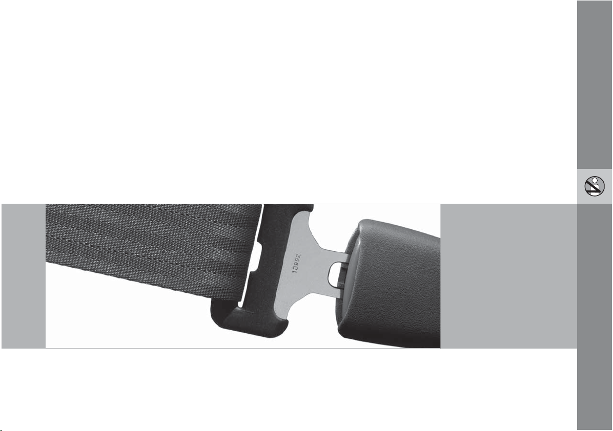
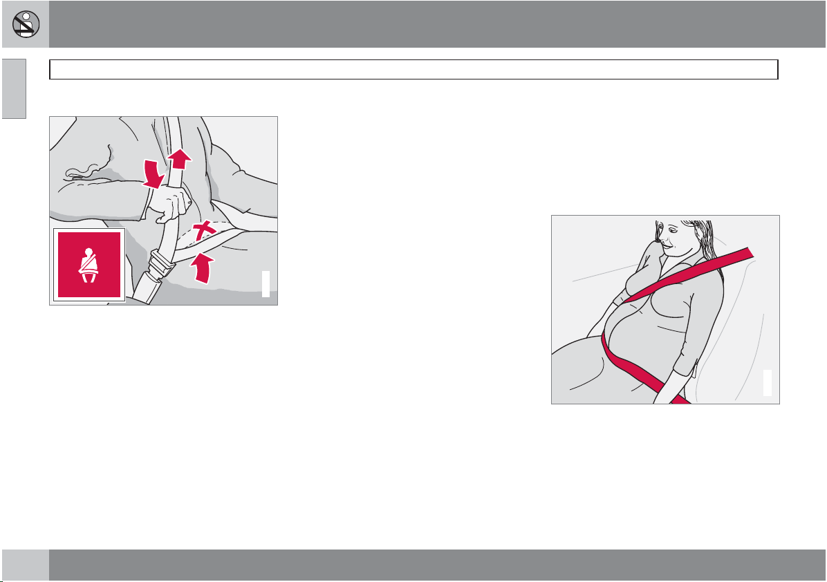
Buckling a seat belt
Pull the belt out far enough to insert the latch
plate into the receptacle until a distinct click is
heard. The seat belt retractor is normally
"unlocked" and you can move freely, provided
that the shoulder belt is not pulled out too far.
The retractor will lock up as follows:
if the belt is pulled out rapidly
•
during braking and acceleration
•
G020104
if the vehicle is leaning excessively
•
when driving in turns
•
When wearing the seat belt remember:
The belt should not be twisted or turned.
•
The lap section of the belt must be posi-
•
tioned low on the hips (not pressing against
the abdomen).
Make sure that the shoulder belt is rolled
•
up into its retractor and that the shoulder
and lap belts are taut.
Unbuckling the seat belt
To remove the seat belt, press the red section
on the seat belt receptacle. Before exiting the
vehicle, check that the seat belt retracts fully
after being unbuckled. If necessary, guide the
belt back into the retractor slot.
Seat belt reminder
The seat belt reminder consists of an audible
signal, an indicator light above the rearview
mirror, and a symbol in the instrument panel
that alert the driver that the seat belt is not
properly fastened.
Seat belt use during pregnancy
G020105
The seat belt should always be worn during
pregnancy. But it is crucial that it be worn in the
correct way. The diagonal section should wrap
over the shoulder then be routed between the
breasts and to the side of the belly. The lap
section should lay flat over the thighs and as
low as possible under the belly. It must never
be allowed to ride upward. Remove all slack
18
Page 19
01 Safety
from the belt and insure that it fits close to the
body without any twists.
As a pregnancy progresses, pregnant drivers
should adjust their seats and steering wheel
such that they can easily maintain control of the
vehicle as they drive (which means they must
be able to easily operate the foot pedals and
steering wheel). Within this context, they
should strive to position the seat with as large
a distance as possible between their belly and
the steering wheel.
Child seats
Please see page 33 for information on securing child seats with the seat belts.
Seat belt maintenance
Check periodically that the seat belts are in
good condition. Use water and a mild detergent for cleaning. Check seat belt mechanism
function as follows: attach the seat belt and pull
rapidly on the strap.
WARNING
Never use a seat belt for more than one
•
occupant.
Never wear the shoulder portion of the
•
belt under the arm, behind the back or
otherwise out of position. Such use
could cause injury in the event of an
accident.
Seat belts lose much of their strength
•
when exposed to violent stretching and
should be replaced after any collision,
even if they appear to be undamaged.
Never repair the belt yourself; have this
•
work done by an authorized Volvo service technician only.
Any device used to induce slack into the
•
shoulder belt portion of the three-point
belt system will have a detrimental
effect on the amount of protection available to you in the event of a collision.
The seat back should not be tilted too
•
far back. The shoulder belt must be taut
in order to function properly.
Do not use child safety seats or child
•
booster cushions/backrests in the front
passenger's seat. We also recommend
that children who have outgrown these
devices sit in the rear seat with the seat
belt properly fastened.
Seat belts
01
19
Page 20
01 Safety
01
Supplemental Restraint System
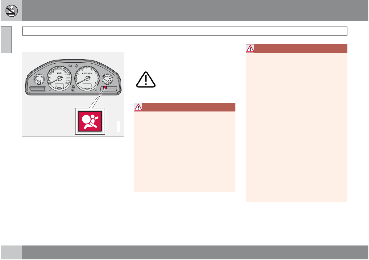
Supplemental Restraint System (SRS)
SRS warning light
As an enhancement to the three-point seat
belts, your Volvo is equipped with a Supplemental Restraint System (SRS). Volvo's SRS
consists of seat belt pretensioners, front airbags, side impact airbags, the occupant
weight sensor, and inflatable curtains. All of
these systems are monitored by the SRS control module. An SRS warning light in the instrument panel (see the illustration) illuminates
when the ignition key is turned to position I,
II, or III, and will normally go out after approximately 7 seconds if no faults are detected in
the system.
Where applicable, a text message will also be
displayed when the SRS warning light illuminates. If this warning symbol is not functioning
properly, the general warning symbol
illuminates and a text message will
be displayed.
WARNING
If the SRS warning light stays on after
•
the engine has started or if it illuminates
G027284
while you are driving, have the vehicle
inspected by a trained and qualified
Volvo service technician as soon as
possible.
Never try to repair any component or
•
part of the SRS yourself. Any interference in the system could cause malfunction and serious injury. All work on
these systems should be performed by
a trained and qualified Volvo service
technician.
WARNING
If your vehicle has been subjected to flood
conditions (e.g. soaked carpeting/standing
water on the floor of the vehicle) or if your
vehicle has become flood-damaged in any
way, do not attempt to start the vehicle or
put the key in the ignition before disconnecting the battery. This may cause airbag
deployment which could result in personal
injury. Have the vehicle towed to a trained
and qualified Volvo service technician for
repairs.
Automatic transmission:
Before attempting to tow the vehicle, use
the following procedure to override the
shiftlock system to move the gear selector
to the neutral position:
Switch off the ignition for at least
•
10 minutes and disconnect the battery
Wait at least one minute.
•
Insert the key in the ignition and turn it
•
to position II.
Press firmly on the brake pedal.
•
Move the gear selector from (P)ark to
•
the (N)eutral position.
20
Page 21
01 Safety
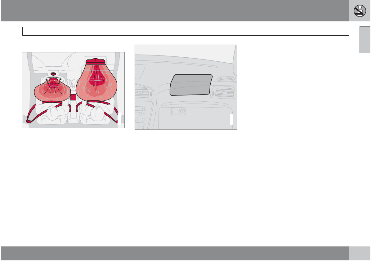
The front airbag system
The front airbags supplement the three-point
seat belts. For these airbags to provide the
protection intended, seat belts must be worn
at all times.
The front airbag system includes gas generators surrounded by the airbags, and deceleration sensors that activate the gas generators,
causing the airbags to be inflated with nitrogen
gas.
G020111
As the movement of the seats' occupants compresses the airbags, some of the gas is expelled at a controlled rate to provide better
cushioning. Both seat belt pretensioners also
deploy, minimizing seat belt slack. The entire
process, including inflation and deflation of the
airbags, takes approximately one fifth of a second.
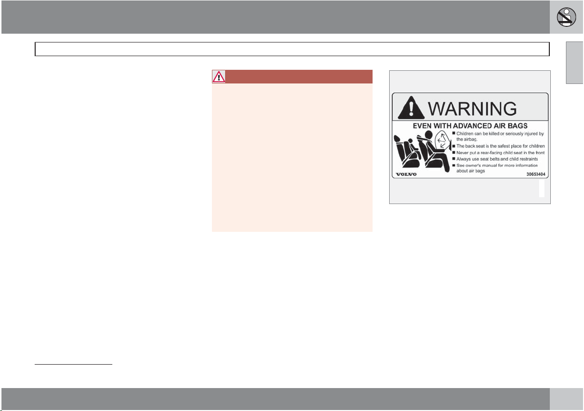
The location of the front airbags is indicated by
"SRS AIRBAG" embossed on the steering
wheel pad and above the glove compartment,
and by decals on both sun visors and on the
front and far right side of the dash.
G031006
Front airbags
The driver's side front airbag is folded and
•
located in the steering wheel hub.
The passenger's side front airbag is folded
•
behind a panel located above the glove
compartment.
01
``
21
Page 22
01 Safety
01
Front airbags
WARNING
The airbags in the vehicle are designed
•
to be a SUPPLEMENT to–not a replacement for–the three-point seat belts. For
maximum protection, wear seat belts at
all times. Be aware that no system can
prevent all possible injuries that may
occur in an accident.
Never drive a vehicle with a steering
•
wheel-mounted airbag with your hands
on the steering wheel pad/airbag housing.
The front airbags are designed to help
•
prevent serious injury. Deployment
occurs very quickly and with considerable force. During normal deployment
and depending on variables such as
seating position, one may experience
abrasions, bruises, swellings, or other
injuries as a result from deployment of
one or both of the airbags.
When installing any accessory equip-
•
ment, make sure that the front airbag
system is not damaged. Any interference in the system could cause malfunction.
Front airbag deployment
Front airbag deployment
•
The front airbags are designed to deploy
•
during certain frontal or front-angular collisions, impacts, or decelerations, depending on the crash severity, angle, speed and
object impacted. The airbags may also
deploy in certain non-frontal collisions
where rapid deceleration occurs.
The SRS sensors, which trigger the front
•
airbags, are designed to react to both the
impact of the collision and the inertial
forces generated by it, and to determine if
the intensity of the collision is sufficient for
the seat belt pretensioners and/or airbags
to be deployed.
However, not all frontal collisions activate the
front airbags.
If the collision involves a nonrigid object
•
(e.g., a snow drift or bush), or a rigid, fixed
object at a low speed, the front airbags will
not necessarily deploy.
Front airbags do not normally deploy in a
•
side impact collision, in a collision from the
rear or in a rollover situation.
The amount of damage to the bodywork
•
does not reliably indicate if the airbags
should have deployed or not.
NOTE
Deployment of front airbags occurs only
•
one time during an accident. In a collision where deployment occurs, the airbags and seat belt pretensioners activate. Some noise occurs and a small
amount of powder is released. The
release of the powder may appear as
smoke-like matter. This is a normal
characteristic and does not indicate fire.
Volvo's front airbags use special sen-
•
sors that are integrated with the front
seat buckles. The point at which the airbag deploys is determined by whether
or not the seat belt is being used, as well
as the severity of the collision.
Collisions can occur where only one of
•
the airbags deploys. If the impact is less
severe, but severe enough to present a
clear injury risk, the airbags are triggered at partial capacity. If the impact is
more severe, the airbags are triggered
at full capacity.
Should you have questions about any component in the SRS system, please contact a
trained and qualified Volvo service technician
or Volvo Customer Support:
In the USA
Volvo Cars of North America, LLC
22
Page 23
01 Safety
Customer Care Center
P.O. Box 914 Rockleigh, New Jersey
07647-0914
1-800-458-1552
www.volvocars.us
In Canada
Volvo Cars of Canada Corp.
National Customer Service
175 Gordon Baker Road
North York, Ontario M2H 2N7
1-800-663-8255
www.volvocanada.com
WARNING
Do not use child safety seats or child
•
booster cushions/backrests in the front
passenger's seat. We also recommend
that occupants under 4 feet 7 inches
(140 cm) in height who have outgrown
these devices sit in the rear seat with the
seat belt fastened
Never drive with the airbags deployed.
•
The fact that they hang out can impair
the steering of your vehicle. Other
safety systems can also be damaged.
The smoke and dust formed when the
•
airbags are deployed can cause skin
and eye irritation in the event of prolonged exposure.
1
.
Front airbags
Airbag decal on outside of both sun visors
01
G032934
1
See also the Occupant Weight Sensor information on page 25.
``
23
Page 24
01 Safety
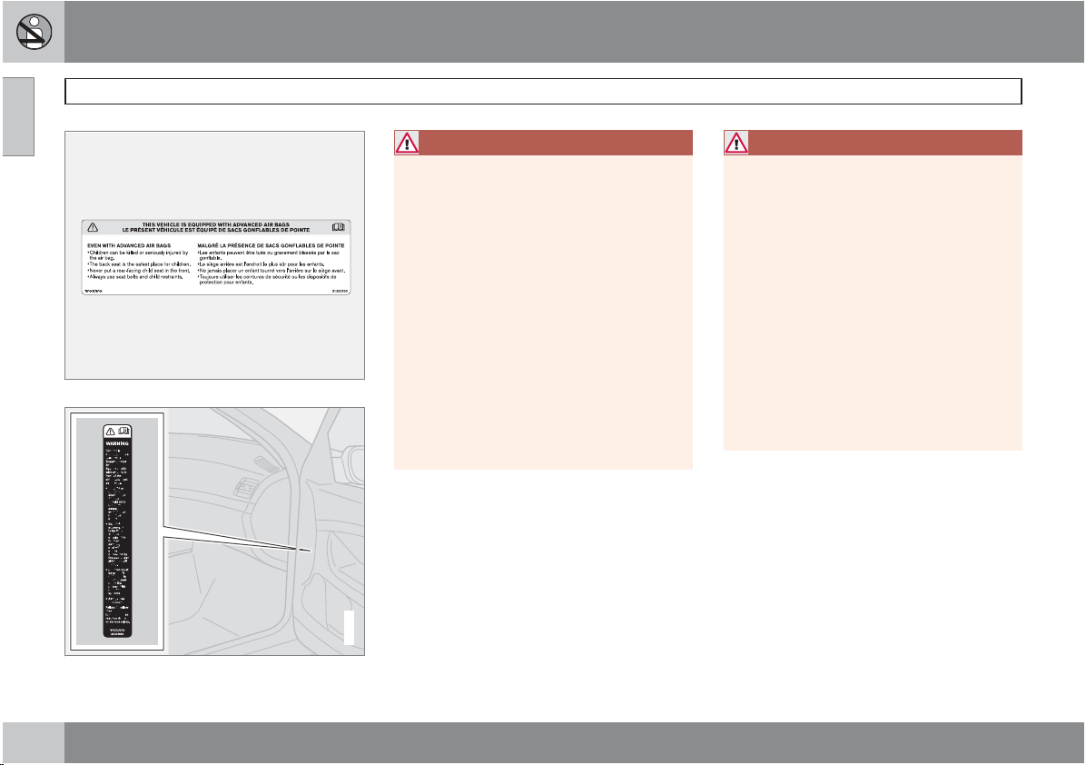
01
Front airbags
Airbag decal on the passenger's dashboard
G032525
WARNING
Children must never be allowed in the
•
front passenger's seat. Volvo recommends that ALL occupants (adults and
children) shorter than 4 feet 7 inches
(140 cm) be seated in the back seat of
any vehicle with a passenger-side front
airbag. See page 33 for guidelines.
Occupants in the front passenger's seat
•
must never sit on the edge of the seat,
sit leaning toward the instrument panel
or otherwise sit out of position.
The occupant's back must be as upright
•
as comfort allows and be against the
seat back with the seat belt properly
fastened.
Feet must be on the floor, e.g., not on
•
the dash, seat or out of the window.
WARNING
No objects or accessory equipment,
•
e.g. dashboard covers, may be placed
on, attached to, or installed near the air
bag hatch (the area above the glove
compartment) or the area affected by
airbag deployment, see page 22.
There should be no loose articles, e.g.
•
coffee cups, on the floor, seat, or dashboard area.
Never try to open the airbag cover on
•
the steering wheel or the passenger's
side dashboard. This should only be
done by a trained and qualified Volvo
service technician.
Failure to follow these instructions can
result in injury to the vehicle occupants.
Airbag decal in the front passenger's door opening
24
G032243
Page 25
01 Safety
Disabling the passenger's side front
airbag
Occupant Weight Sensor (OWS) indicator light
Volvo recommends that ALL occupants (adults
and children) shorter than 4 feet 7 inches
(140 cm) be seated in the rear seat of any vehicle with a passenger's side front airbag, and be
properly restrained. Children should always be
seated in child restraints appropriate for their
size and weight. See also the child safety recommendations beginning on page 33.
The Occupant Weight Sensor (OWS) is
designed to meet the regulatory requirements
of Federal Motor Vehicle Safety Standard
(FMVSS) 208 and is designed to disable (will
not inflate) the passenger's side front airbag
under certain conditions.
The OWS works with sensors that are part of
the front passenger's seat and seat belt. The
sensors are designed to detect the presence of
a properly seated occupant and determine if
the passenger's side front airbag should be
enabled (may inflate) or disabled (will not
inflate).
The OWS will disable (will not inflate) the passenger's side front airbag when:
the front passenger's seat is unoccupied,
•
or has small/medium objects in the front
G027050
seat,
the system determines that an infant is
•
present in a rear-facing infant seat that is
installed according to the manufacturer's
instructions,
the system determines that a small child is
•
present in a forward-facing child restraint
that is installed according to the manufacturer's instructions,
the system determines that a small child is
•
present in a booster seat,
a front passenger takes his/her weight off
•
of the seat for a period of time,
a child or a small person occupies the front
•
passenger's seat.
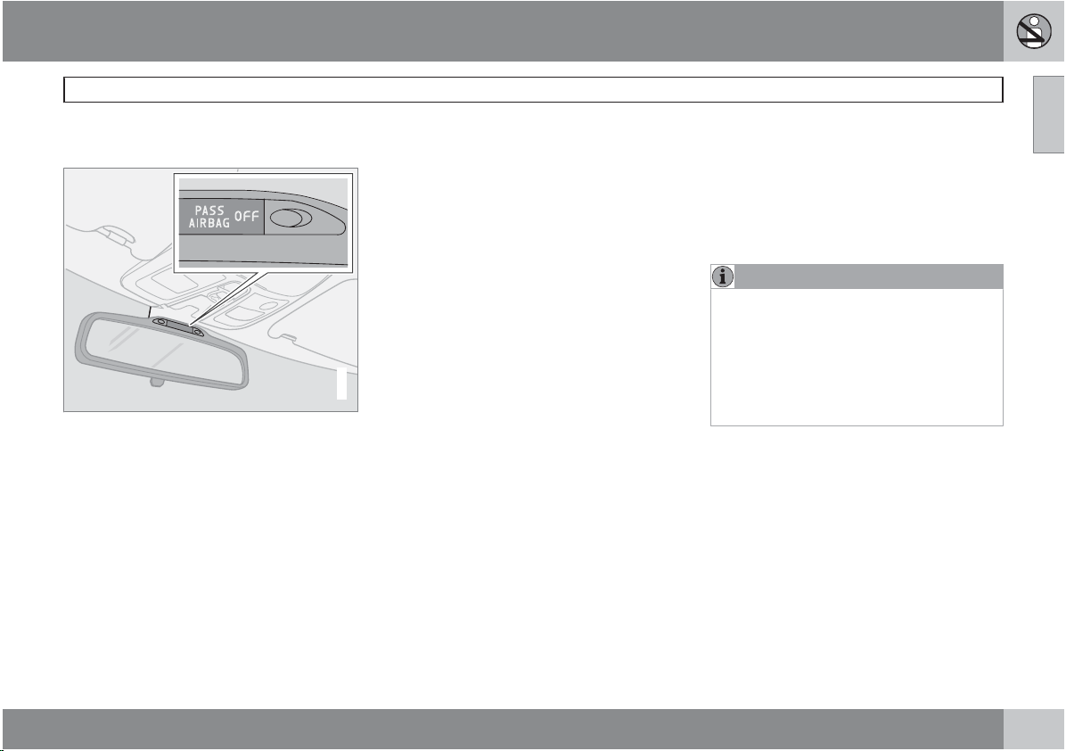
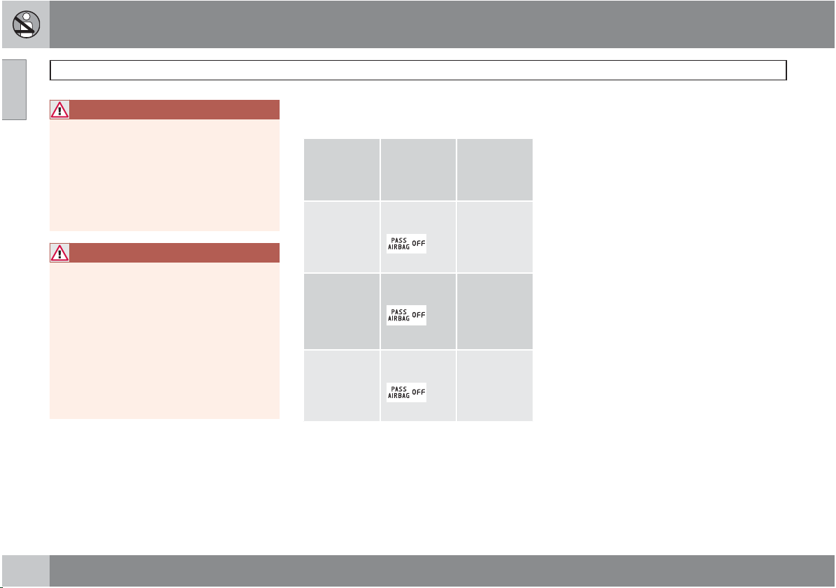
Occupant Weight Sensor (OWS)
The OWS uses a
OFF
indicator light which will illuminate and
stay on to remind you that the passenger's side
front airbag is disabled. The
AIRBAG OFF
overhead console, near the base of the rearview mirror.
NOTE
The PASSENGER AIRBAG OFF indicator
lamp will illuminate for a short period of time
when the ignition is turned on to confirm it
is functional. When the front passenger's
seat is not occupied (empty seat) or in the
event that the passenger's side front airbag
is enabled (may inflate), the
AIRBAG OFF
However, if a fault is detected in the
system:
The PASSENGER AIRBAG OFF indicator
•
light will stay on.
The SRS warning light (see page 20) will
•
come on and stay on.
The message PASS. AIRBAG OFF
•
SERVICE URGENT
the information display.
PASSENGER AIRBAG
PASSENGER
indicator light is located in the
PASSENGER
indicator lamp will be off.
will be displayed in
01
``
25
Page 26
01 Safety
01
Occupant Weight Sensor (OWS)
WARNING
If a fault in the system is detected and indicated as explained on the previous page, be
aware that the passenger's side front airbag
will not deploy in the event of a collision.
In this case, the safety systems and Occupant Weight Sensor should be inspected by
a trained and qualified Volvo service technician as soon as possible.
WARNING
Never try to open, remove, or repair any
•
components in the OWS system. This
could result in system malfunction.
Maintenance or repairs should only be
carried out by an authorized Volvo service technician.
The front passenger's seat should not
•
be modified in any way. This could
reduce pressure on the seat cushion,
which might interfere with the OWS system's function.
The OWS is designed to disable (will not inflate)
the passenger's side front airbag when a rear
facing infant seat, a forward-facing child
restraint, or a booster seat is detected. The
PASSENGER AIRBAG OFF indicator lamp
will illuminate and stay on to remind you that
the passenger's side front airbag is disabled
(see the following table).
Passenger's
seat occupancy status
OWS indicator light status
Passenger's
side front
airbag status
Seat unoccupied
OWS indicator light
not lit
Seat occupied by low
OWS indica-
tor light
weight
occupant/
A
object
Seat occupied by
lights up
OWS indica-
tor light
heavy occupant/object
A
Volvo recommends that children always be properly
restrained in appropriate child restraints in the rear seats.In
rare situations when the seat belt is not properly fastened,
some child restraints may not be detected by the OWS
because there is very little weight on the vehicle seat cushion. In these cases the passenger's side front airbag may be
disabled, but the
indicator lamp will not be lit. Do not assume that the pas-
senger's side front airbag is disabled unless the
not lit
PASSENGER AIRBAG OFF
is
is
Passenger's
side front
airbag disabled
Passenger's
side front
airbag disabled
Passenger's
side front
airbag enabled
PAS-
SENGER AIRBAG OFF indicator lamp is lit. Make
sure the child restraint is properly installed (turn the vehicle
off, remove the child restraint from the vehicle and reinstall
the restraint following the child restraint manufacturer's
instructions) and that the PASSENGER AIRBAG
OFFindicator lamp is on, or move the child restraint to the
rear seat.
The OWS is designed to enable (may inflate)
the passenger's side front airbag anytime the
system senses that a person of adult size is
sitting properly in the front passenger's seat.
PASSENGER AIRBAG OFF indicator
The
lamp will be off and remain off.
If a person of adult size is sitting in the front
passenger's seat, but the PASSENGER
AIRBAG OFF
indicator lamp is on, it is possible that the person isn't sitting properly in the
seat. If this happens:
Turn the vehicle off and ask the person to
•
place the seatback in an upright position.
Have the person sit upright in the seat,
•
centered on the seat cushion, with the person's legs comfortably extended.
Restart the vehicle and have the person
•
remain in this position for about two
minutes. This will allow the system to
detect that person and enable the passenger's frontal airbag.
If the PASSENGER AIRBAG OFF indica-
•
tor lamp remains on even after this, the
person should be advised to ride in the rear
seat.
26
Page 27
01 Safety
This condition reflects limitations of the OWS
classification capability. It does not indicate
OWS malfunction.
Modifications
If you are considering modifying your vehicle in
any way to accommodate a disability, for
example by altering or adapting the driver's or
front passenger's seat(s) and/or airbag systems, please contact Volvo at:
In the USA
Volvo Cars of North America, LLC
Customer Care Center
P.O. Box 914 Rockleigh, New Jersey
07647-0914
1-800-458-1552
In Canada
Volvo Cars of Canada Corp.
National Customer Service
175 Gordon Baker Road
North York, Ontario M2H 2N7
1-800-663-8255
WARNING
No objects that add to the total weight
•
on the seat should be placed on the
front passenger's seat. If a child is
seated in the front passenger's seat
with any additional weight, this extra
weight could cause the OWS system to
enable the airbag, which might cause it
to deploy in the event of a collision,
thereby injuring the child.
The seat belt should never be wrapped
•
around an object on the front passenger's seat. This could interfere with the
OWS system's function.
The front passenger's seat belt should
•
never be used in a way that exerts more
pressure on the passenger than normal.
This could increase the pressure exerted on the weight sensor by a child, and
could result in the airbag being enabled,
which might cause it to deploy in the
event of a collision, thereby injuring the
child.
Occupant Weight Sensor (OWS)
WARNING
Keep the following points in mind with
respect to the OWS system. Failure to follow
these instructions could adversely affect the
system's function and result in serious injury
to the occupant of the front passenger's
seat:
The full weight of the front seat passen-
•
ger should always be on the seat cushion. The passenger should never lift
him/herself off the seat cushion using
the armrest in the door or the center
console, by pressing the feet on the
floor, by sitting on the edge of the seat
cushion, or by pressing against the
backrest in a way that reduces pressure
on the seat cushion. This could cause
OWS to disable the front passenger's
side airbag.
Do not place any type of object on the
•
front passenger's seat in such a way
that jamming, pressing, or squeezing
occurs between the object and the front
seat, other than as a direct result of the
correct use of the Automatic Locking
Retractor/Emergency Locking Retractor (ALR/ELR) seat belt, see page 33.
No objects should be placed under the
•
front passenger's seat. This could interfere with the OWS system's function.
01
27
Page 28
01 Safety
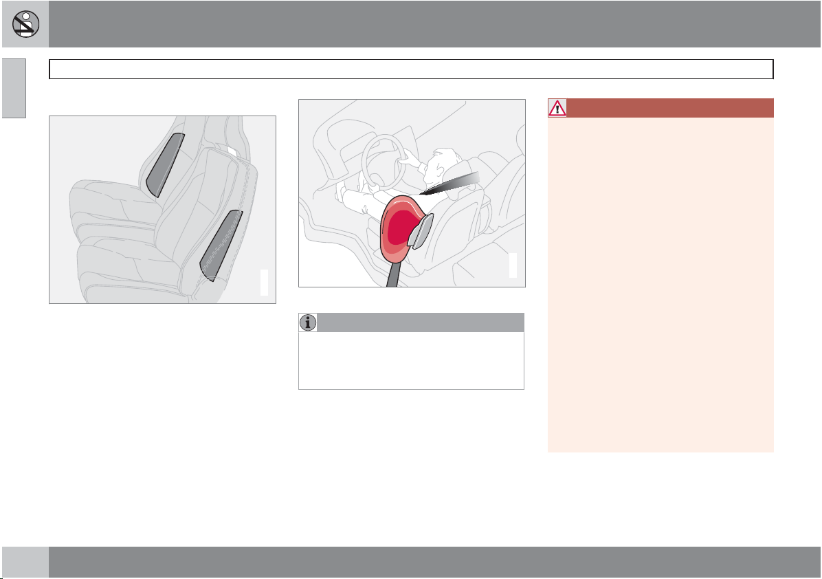
01
Side impact (SIPS) airbag
Side impact airbags – front seats only
Location of the side impact (SIPS) airbag
As an enhancement to the structural side
impact protection built into your vehicle, the
vehicle is also equipped with Side Impact Protection System (SIPS) airbags.
The SIPS airbag system is designed to help
increase occupant protection in the event of
certain side impact collisions. The SIPS airbags are designed to deploy only during certain side-impact collisions, depending on the
crash severity, angle, speed and point of
impact.
G020118
Components in the SIPS airbag system
NOTE
SIPS airbag deployment (one airbag) occurs
only on the side of the vehicle affected by
the impact. The airbags are not designed to
deploy in all side impact situations.
Components in the SIPS airbag system
This SIPS airbag system consists of gas generators and side airbag modules built into the
outboard sides of both front seat backrests.
G025315
WARNING
The SIPS airbag system is a supple-
•
ment to the structural Side Impact Protection System and the three-point seat
belt system. It is not designed to deploy
during collisions from the front or rear of
the vehicle or in rollover situations.
The use of seat covers on the front seats
•
may impede SIPS airbag deployment.
No objects, accessory equipment or
•
stickers may be placed on, attached to
or installed near the SIPS airbag system
or in the area affected by SIPS airbag
deployment.
Never try to open or repair any compo-
•
nents of the SIPS airbag system. This
should be done only by a trained and
qualified Volvo service technician.
In order for the SIPS airbag to provide
•
its best protection, both front seat
occupants should sit in an upright position with the seat belt properly fastened.
Failure to follow these instructions can
•
result in injury to the occupants of the
vehicle in the event of an accident.
28
Page 29
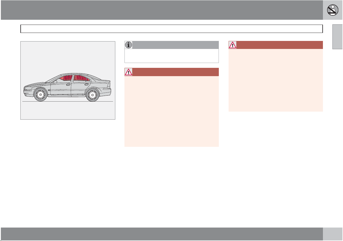
01 Safety
This system consists of inflatable curtains
located along the sides of the roof liners,
stretching from the center of both front side
windows to the rear edge of the rear side door
windows. It is designed to help protect the
heads of the occupants of the front seats and
the occupant of the outboard rear seating positions in certain side impact collisions.
In certain side impacts, both the Inflatable Curtain (VIC) and the Side Impact Airbag System
(SIPS-bag) will deploy, whereas, in some
cases, only the Inflatable Curtain (VIC) will
deploy. In cases where both the VIC and the
SIPS-bag deploy, this will occur simultaneously.
NOTE
If the inflatable curtain deploys, it remains
inflated for approximately 3 seconds.
WARNING
The VIC system is a supplement to the
•
Side Impact Protection System. It is not
designed to deploy during collisions
from the front or rear of the vehicle or in
rollover situations.
Never try to open or repair any compo-
•
G027218
nents of the VIC system. This should be
done only by a trained and qualified
Volvo service technician.
Never hang heavy items from the ceiling
•
handles. This could impede deployment
of the Inflatable curtain.
Volvo Inflatable Curtain (VIC)
WARNING
In order for the VIC to provide its best protection, both front seat occupants and both
outboard rear seat occupants should sit in
an upright position with the seat belt properly fastened; adults using the seat belt and
children using the proper child restraint system. Only adults should sit in the front seats.
Children must never be allowed in the front
passenger seat. See 33 for guidelines.
Failure to follow these instructions can
result in injury to the vehicle occupants in an
accident.
01
29
Page 30
01 Safety
01
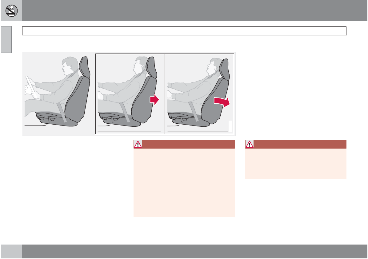
Whiplash Protection System (WHIPS)
Whiplash Protection System (WHIPS) – front seats only
The WHIPS system consists of specially
designed hinges and brackets on the front seat
backrests designed to help absorb some of the
energy generated in a collision from the rear
(when the vehicle is "rearended").
In the event of a collision of this type, the hinges
and brackets of the front seat backrests are
designed to change position slightly to allow
the backrest/head restraint to help support the
occupant's head before moving slightly rearward. This movement helps absorb some of
the forces that could result in whiplash.
WARNING
The WHIPS system is designed to sup-
•
plement the other safety systems in
your vehicle. For this system to function
properly, the three-point seat belt must
be worn. Please be aware that no system can prevent all possible injuries that
may occur in an accident.
The WHIPS system is designed to func-
•
tion in certain collisions from the rear,
depending on the crash severity, angle
and speed.
G020347
WARNING
Occupants in the front seats must never sit
out of position. The occupant's back must
be as upright as comfort allows and be
against the seat back with the seat belt
properly fastened.
30
Page 31

01 Safety
G020125G020126
WARNING
Boxes, suitcases, etc. wedged behind
•
the front seats could impede the function of the WHIPS system.
If the rear seat backrests are folded
•
down, cargo must be secured to prevent it from sliding forward against the
front seat backrests in the event of a
collision from the rear. This could interfere with the action of the WHIPS system.
If your vehicle has been involved in a
•
rear-end collision, the front seat backrests must be inspected by a trained and
qualified Volvo service technician, even
if the seats appear to be undamaged.
Certain components in the WHIPS system may need to be replaced.
Do not attempt to service any compo-
•
nent in the WHIPS system yourself.
Any contact between the front seat
•
backrests and the folded rear seat
could impede the function of the WHIPS
system. If the rear seat is folded down,
the occupied front seats must be
adjusted forward so that they do not
touch the folded rear seat.
Whiplash Protection System (WHIPS)
01
31
Page 32

01 Safety
01
Child safety
Children should be seated safely
Volvo recommends the proper use of restraint
systems for all occupants including children.
Remember that, regardless of age and size, a
child should always be properly restrained in a
vehicle.
Your vehicle is also equipped with ISOFIX/
LATCH attachments, which make it more convenient to install child seats.
Some restraint systems for children are
designed to be secured in the vehicle by lap
belts or the lap portion of a lap-shoulder belt.
Such child restraint systems can help protect
children in vehicles in the event of an accident
only if they are used properly. However, children could be endangered in a crash if the child
restraints are not properly secured in the vehicle. Failure to follow the installation instructions
for your child restraint can result in your child
striking the vehicle's interior in a sudden stop.
Holding a child in your arms is NOT a suitable
substitute for a child restraint system. In an
accident, a child held in a person's arms can
be crushed between the vehicle's interior and
an unrestrained person. The child could also be
injured by striking the interior, or by being ejected from the vehicle during a sudden maneuver
or impact. The same can also happen if the
infant or child rides unrestrained on the seat.
Other occupants should also be properly
restrained to help reduce the chance of injuring
or increasing the injury of a child.
All states and provinces have legislation governing how and where children should be carried in a vehicle. Find out the regulations
existing in your state or province. Recent accident statistics have shown that children are
safer in rear seating positions than front seating
positions when properly restrained. A child
restraint system can help protect a child in a
vehicle. Here's what to look for when selecting
a child restraint system:
It should have a label certifying that it
•
meets applicable Federal Motor Vehicle
Safety Standards (FMVSS 213) – or in Canada, CMVSS 213.
Make sure the child restraint system is
•
approved for the child's height, weight and
development – the label required by the
standard or regulation, or instructions for
infant restraints, typically provide this information.
In using any child restraint system, we urge
•
you to carefully look over the instructions
that are provided with the restraint. Be sure
you understand them and can use the
device properly and safely in this vehicle.
A misused child restraint system can result
in increased injuries for both the infant or
child and other occupants in the vehicle.
When a child has outgrown the child safety
seat, you should use the rear seat with the
standard seat belt fastened. The best way to
help protect the child here is to place the child
on a cushion so that the seat belt is properly
located on the hips, see page 34. Legislation
in your state or province may mandate the use
of a child seat or cushion in combination with
the seat belt, depending on the child's age and/
or size. Please check local regulations.
A specially designed and tested booster cushion (not available in Canada) can be obtained
from your Volvo retailer for children weighing
33 – 80 lb. (15 – 36 kg) and 38 – 54 inches
(97 – 137 cm) in height.
32
Page 33

01 Safety
WARNING
Do not use child safety seats or child
•
booster cushions/backrests in the front
passenger's seat. We also recommend
that children under 4 feet 7 inches
(140 cm) in height who have outgrown
these devices sit in the rear seat with the
seat belt fastened.
Keep vehicle doors and trunk locked
•
and keep keys out of a child's reach.
Unsupervised children could lock themselves in an open trunk and risk injury.
Children should be taught not to play in
vehicles.
On hot days, the temperature in the
•
vehicle interior can rise very quickly.
Exposure to these high temperatures for
even a short period of time can cause heatrelated injury or death. Small children are
particularly at risk.
Automatic Locking Retractor/
Emergency Locking Retractor (ALR/
ELR)
To make child seat installation easier, each
seat belt (except for the driver's belt) is equipped with a locking mechanism to help keep the
seat belt taut.
When attaching the seat belt to a child seat:
1. Attach the seat belt to the child seat
according to the child seat manufacturer's
instructions.
2. Pull the seat belt out as far as possible.
3. Insert the seat belt latch plate into the
buckle (lock) in the usual way.
4. Release the seat belt and pull it taut around
the child seat. A sound from the seat belt
retractor will be audible at this time and
is normal.
The belt will now be locked in place.
This function is automatically disabled when
the seat belt is unlocked and the belt is fully
retracted.
WARNING
Do not use child safety seats or child
booster cushions/backrests in the front
passenger's seat. We also recommend that
children who have outgrown these devices
sit in the rear seat with the seat belt properly
fastened.
Volvo's recommendations
Why does Volvo believe that no child should sit
in the front seat of a vehicle? It's quite simple
really. A front airbag is a very powerful device
designed, by law, to help protect an adult.
Child safety
Because of the size of the airbag and its speed
of inflation, a child should never be placed in
the front seat, even if he or she is properly belted or strapped into a child safety seat. Volvo
has been an innovator in safety for over seventy-five years, and we'll continue to do our
part. But we need your help. Please remember
to put your children in the back seat, and
buckle them up.
Volvo has some very specific
recommendations:
Always wear your seat belt.
•
Airbags are a SUPPLEMENTAL safety
•
device which, when used with a threepoint seat belt can help reduce serious
injuries during certain types of accidents.
Volvo recommends that you do not disconnect the airbag system in your vehicle.
Volvo strongly recommends that everyone
•
in the vehicle be properly restrained.
Volvo recommends that ALL occupants
•
(adults and children) shorter than 4 feet
7 inches (140 cm) be seated in the back
seat of any vehicle with a front passenger
side airbag.
Drive safely!
01
33
Page 34

01 Safety
01
Child restraint systems
Child restraints
Infant seat
There are three main types of child restraint
systems: infant seats, convertible seats, and
booster cushions. They are classified according to the child's age and size.
The following section provides general information on securing a child restraint using a
three-point seat belt. Refer to 40 for information on securing a child restraint using ISOFIX
lower anchors and/or top tether anchorages.
G026491
Convertible seat
WARNING
A child seat should never be used in the
front passenger seat of any vehicle with a
front passenger airbag – not even if the
"
Passenger airbag off" symbol near the
rear-view mirror is illuminated (on vehicles
equipped with Occupant Weight Sensor). If
the severity of an accident were to cause the
airbag to inflate, this could lead to serious
injury or death to a child seated in this position.
G026503
Booster cushion
WARNING
Always refer to the child restraint manufacturer's instructions for detailed information
on securing the restraint.
G026489
34
Page 35

01 Safety
WARNING
When not in use, keep the child restraint
•
system secured or remove it from the
passenger compartment to help prevent it from injuring passengers in the
event of a sudden stop or collision.
A small child's head represents a con-
•
siderable part of its total weight and its
neck is still very weak. Volvo recommends that children up to age 4 travel,
properly restrained, facing rearward. In
addition, Volvo recommends that children should ride rearward facing, properly restrained, as long as possible.
Child restraint systems
01
35
Page 36

01 Safety
01
Infant seats
Securing an infant seat with a seat belt
Do not place the infant seat in the front passenger's seat
NOTE
Refer to 41 for information on securing a
child restraint using ISOFIX lower anchors
and/or top tether anchorages.
1. Place the infant seat in the rear seat of the
vehicle.
2. Attach the seat belt to the infant seat
according to the manufacturer's instructions.
G026417
Positioning the seat belt through the infant seat
WARNING
An infant seat must be in the rear-facing
•
position only.
The infant seat should not be positioned
•
behind the driver's seat unless there is
adequate space for safe installation.
WARNING
A child seat should never be used in the
front passenger seat of any vehicle with a
front passenger airbag – not even if the
Passenger airbag off symbol near the
rear-view mirror is illuminated (on vehicles
equipped with Occupant Weight Sensor). If
the severity of an accident were to cause the
airbag to inflate, this could lead to serious
injury or death to a child seated in this position.
3. Fasten the seat belt by inserting the latch
G026493
plate into the buckle (lock) until a distinct
click is audible.
36
Page 37

01 Safety
Fasten the seat belt
4. Pull the shoulder section of the seat belt
out as far as possible to activate the belt's
automatic locking function.
NOTE
The locking retractor will automatically
release when the seat belt is unbuckled and
allowed to retract fully.
5. Press the infant seat firmly in place, let the
seat belt retract and pull it taut. A sound
G026492
from the seat belt retractor's automatic
locking function will be audible at this time
and is normal. The seat belt should now be
locked in place.
Infant seats
Ensure that the seat is securely in place
6. Push and pull the infant seat to ensure that
it is held securely in place by the seat belt.
WARNING
It should not be possible to move the child
restraint more than 1 in. (2.5 cm) in any
direction.
The infant seat can be removed by unbuckling
the seat belt and letting it retract completely.
01
G026498
Pull out the shoulder section of the seat belt
G026494
37
Page 38

01 Safety
01
Convertible seats
Securing a convertible seat with a seat
belt
Do not place the convertible seat in the front passenger's seat
NOTE
Refer to information on securing a child
restraint using ISOFIX lower anchors and/or
top tether anchorages, see page 41.
Convertible seats can be used in either a forward or rearward-facing position, depending
on the age and size of the child.
Route the seat belt through the convertible seat
G026420
WARNING
Always use a convertible seat that is suitable for the child's age and size. See the
convertible seat manufacturer's recommendations.
1. Place the convertible seat in the rear seat
of the vehicle.
WARNING
A small child's head represents a con-
•
siderable part of its total weight and its
neck is still very weak. Volvo recommends that children up to age 4 travel,
properly restrained, facing rearward. In
addition, Volvo recommends that children should ride rearward facing, properly restrained, as long as possible.
Convertible child seats should be instal-
•
led in the rear seat only.
A rear-facing convertible seat should not
•
G026503
be positioned behind the driver's seat
unless there is adequate space for safe
installation.
2. Attach the seat belt to the convertible seat
according to the manufacturer's instructions.
38
Page 39

01 Safety
Fasten the seat belt
3. Fasten the seat belt by inserting the latch
plate into the buckle (lock) until a distinct
click is audible.
4. Pull the shoulder section of the seat belt
out as far as possible to activate the belt's
automatic locking function.
NOTE
The locking retractor will automatically
release when the seat belt is unbuckled and
allowed to retract fully.
5. Press the convertible seat firmly in place,
let the seat belt retract and pull it taut. A
sound from the seat belt retractor's automatic locking function will be audible at this
time and is normal. The seat belt should
now be locked in place.
G026500
Pull out the shoulder section of the seat belt
6. Push and pull the convertible seat to
ensure that it is held securely in place by
the seat belt.
WARNING
It should not be possible to move the child
restraint more than 1 in. (2.5 cm) in any
direction.
Convertible seats
The convertible seat can be removed by
unbuckling the seat belt and letting it retract
completely.
G026501
Ensure that the seat is securely in place
WARNING
A child seat should never be used in the
front passenger seat of any vehicle with a
front passenger airbag – not even if the
Passenger airbag off" symbol near the
"
rear-view mirror is illuminated (on vehicles
equipped with Occupant Weight Sensor). If
the severity of an accident were to cause the
airbag to inflate, this could lead to serious
injury or death to a child seated in this position.
01
G026502
39
Page 40

01 Safety
01
Booster cushions
Securing a booster cushion
Position the child correctly on the booster cushion
and positioning the seat belt
Booster cushions are recommended for children who have outgrown convertible seats.
1. Place the booster cushion in the rear seat
of the vehicle.
2. With the child properly seated on the
booster cushion, attach the seat belt to or
around the cushion according to the manufacturer's instructions.
3. Fasten the seat belt by inserting the latch
plate into the buckle (lock) until a distinct
click is audible.
4. Ensure that the seat belt is pulled taut and
fits snugly around the child.
WARNING
The hip section of the three-point seat
•
belt must fit snugly across the child's
hips, not across the stomach.
The shoulder section of the three-point
•
seat belt should be positioned across
the chest and shoulder.
The shoulder belt must never be placed
•
behind the child's back or under the
arm.
G026489
40
Page 41

01 Safety
Using the ISOFIX lower child seat
anchors
ISOFIX lower child restraint anchors
Lower anchors for ISOFIX-equipped child
seats are located in the rear, outboard seats,
hidden below the backrest cushions. Symbols
on the seat back upholstery mark the anchor
positions (see the illustration).
To access the anchors:
1. Put the child restraint in position.
2. Kneel on the child restraint to press down
the seat cushion and locate the anchors by
feel.
3. Fasten the attachment on the child
restraint's lower straps to the ISOFIX lower
anchors.
4. Firmly tension the lower child seat straps
according to the manufacturer's instructions.
NOTE
The rear seat's center position is not
•
equipped with ISOFIX lower anchors.
When installing a child restraint in this
position, attach the restraint's top tether
strap (if it is so equipped) to the top
tether anchorage point (for information
G015268
see page 43) and secure the restraint
with the vehicle's center seat belt, see
page 34.
Always follow your child seat manufac-
•
turer's installation instructions, and use
both ISOFIX lower anchors and top
tethers whenever possible.
ISOFIX lower anchors
Fasten the attachment correctly to the ISOFIX
lower anchors
01
G031682
``
41
Page 42

01 Safety
01
ISOFIX lower anchors
WARNING
Be sure to fasten the attachment cor-
•
rectly to the anchor (see the illustration).
If the attachment is not correctly fastened, the child restraint may not be
properly secured in the event of a collision.
The ISOFIX lower child restraint
•
anchors are only intended for use with
child seats positioned in the outboard
seating positions. These anchors are
not certified for use with any child
restraint that is positioned in the center
seating position. When securing a child
restraint in the center seating position,
use only the vehicle's center seat belt.
42
Page 43

01 Safety
Top tether anchors
Top tether anchorage points
Your Volvo is equipped with child restraint top
tether anchorages in all rear seat positions.
Using the top tether anchorages
1. Place the child restraint on the rear seat.
WARNING
Be sure to fasten the child tether attachment
correctly to the anchor. If it is not correctly
fastened, the child seat may not be properly
restrained in the event of a collision.
2. Route the top tether strap under the head
restraint and fasten its attachment to the
anchorage.
G031131
Route the strap under the head restraint
3. Firmly tension the top tether strap according to the child restraint manufacturer's
instructions. Tension the top tether strap
only after the lower anchor straps or the
seat belt have been firmly tensioned.
See 41 for on securing the child restraint to
ISOFIX lower anchors.
G026487
Top tether anchors
WARNING
Never route a top tether strap over the
•
top or around the head restraint. It
should always be routed under the head
restraint.
Child restraint anchorages are designed
•
to withstand only those loads imposed
by correctly fitted child restraints. Under
no circumstances are they to be used
for adult seat belts or harnesses. The
anchorages are not able to withstand
excessive forces on them in the event of
collision if full harness seat belts or adult
seat belts are installed to them. An adult
who uses a belt anchored in a child
restraint anchorage runs a great risk of
suffering severe injuries should a collision occur.
Do not install rear speakers that require
•
the removal of the top tether anchors or
interfere with the proper use of the top
tether strap.
01
43
Page 44

01 Safety
01
Child restraint registration and recalls
Registering a child restraint
Child restraints could be recalled for safety
reasons. You must register your child restraint
to be reached in a recall. To stay informed
about child safety seat recalls, be sure to fill out
and return the registration card that comes
with new child restraints.
Child restraint recall information is readily available in both the U.S. and Canada. For recall
information in the U.S., call the U.S. Government's Auto Safety Hotline at 1-800-424-9393.
In Canada, visit Transport Canada's Child
Safety website at http://www.tc.gc.ca/
roadsafety/childsafety/menu.htm.
44
Page 45

01 Safety
01
45
Page 46

Instrument overview................................................................................ 48
Instrument panel..................................................................................... 50
Indicator and warning symbols............................................................... 52
Buttons in the center console................................................................. 56
Steering wheel adjustment...................................................................... 58
Lighting panel.......................................................................................... 59
Fuel filler door–unlocking manually......................................................... 61
Left-side steering wheel lever................................................................. 62
Right-side steering wheel lever............................................................... 64
Hazard warning flashers, door mirror defroster...................................... 66
Trip computer.......................................................................................... 67
Cruise control.......................................................................................... 69
Parking brake.......................................................................................... 71
12-volt socket......................................................................................... 72
Power windows....................................................................................... 73
Mirrors..................................................................................................... 75
Power moonroof (option)........................................................................ 78
HomeLink® Wireless Control System (option)....................................... 80
G020901
46
Page 47

INSTRUMENTS AND CONTROLS
02
Page 48

02
02 Instruments and controls
Instrument overview
48
G031037
Page 49

02 Instruments and controls
Instrument overview
1 Front fog lights 60
2 Headlights/Parking lights/
switch for unlocking fuel filler
door
3 Rear fog light
4 Turn signals/High/low beams 62
5 Cruise control 67
6 Horn -
7 Instrument panel 50
8 Audio controls in steering
wheel
59
221
G029581
9 Windshield wipers 64
10 Parking brake (hand brake) 69
11 Center console buttons 56
12 Climate control 86
13 Audio system 216
14 12-V socket 57,
15 Hazard warning flashers 66
16 Glove compartment 101
17 Panel vents 88
18 Text display 50
19 Temperature gauge 50
20 Odometer/Trip odometer/
Cruise control indicator
21 Speedometer 50
22 Turn signal indicators 50
23 Tachometer 50
24 Ambient temperature/Clock/
Selected gear indicator
25 Fuel gauge 50
71
50
50
26 Indicator and warning sym-
bols
27 Panel vents 88
28 Instrument lighting 60
29 Not in use
30 Lighting panel 59
31 Reading lights 97
32 Interior lighting 97
33 Moonroof control 76
34 Seat belt reminder 18
35 Rearview mirror 73
36 Lock button, for all doors 112
37 Cut-out button for rear seat
power windows
38 Controls, power windows 73
39 Controls, door mirrors 76
52
73
02
49
Page 50

02 Instruments and controls
Instrument panel
Instrument panel
02
G027133
50
Turn signal indicators – right/left
Text window – The text window displays
information and warning messages.
Temperature gauge – The pointer should
be approximately midway on the gauge
when driving. Do not drive the vehicle if
the warning light is on. The text window
will provide you with additional information. If the engine temperature remains
high, check coolant level – see page 192.
Trip odometer – The trip odometers are
used for measuring shorter distances. The
right-hand digit gives tenth of a mile/kilometer. Press the button for more than
2 seconds to reset. Change between trip
odometers 1 and 2 using one short press
on the button. – The display presents information and warning messages, the ambient temperature, and the clock, etc. When
the ambient temperature is between 23°
and 36 °F (–5° and +2 °C), a snowflake
symbol is shown in the display. This symbol serves as a warning for possible slippery road surfaces. Please note that this
symbol does not indicate a fault with your
car. At low speeds, or when the car is not
moving, the temperature readings may be
slightly higher than the actual ambient temperature.
Odometer
Speedometer
Warning symbol
High beam indicator
Tachometer – The tachometer shows
engine speed in thousands of revolutions
per minute (rpm). Do not drive continuously
with the needle in the red area of the dial,
which indicates maximum allowable
engine rpm range. Instead, shift to a higher
gear or slow the vehicle down. The engine
management system will automatically
prevent excessively high engines speeds.
This will be noticeable as a pronounced
unevenness in engine speed.
Page 51

Gear and driving mode indicator – The currently selected driving mode is displayed
here. If you use the Geartronic function on
the automatic transmission, the currently
selected gear will be displayed.
Ambient temperature gauge – This display
indicates the air temperature outside your
vehicle. A "snowflake" symbol in the text
window is displayed when the temperature
is in the range of 23 – 36 °F (–5 – +2 °C).
Please note that this symbol does not indicate a fault with your vehicle. At low
speeds or when the vehicle is not moving,
the temperature readings may be slightly
higher than the actual ambient temperature.
Clock/set button – Turn the button to set
the clock.
Fuel gauge - see page 240 for more information on fuel tank volume. When the
warning light in the gauge comes on, the
vehicle should be refueled as soon as possible. The Trip computer section (see
page 67) provides more information on
fuel level and consumption.
Indicator and warning symbols – The indicator and warning symbols
you turn the ignition key to the driving position (position II) before starting.
1
light up when
02 Instruments and controls
Instrument panel
02
1
On certain engines, the symbol for low oilpressure is not used. Instead, a text warning is provided in the information display.
51
Page 52

02 Instruments and controls
Indicator and warning symbols
Warning symbol in the center of the
instrument panel
02
Red symbol - Stop the vehicle as soon as possible in a suitable location and read the message shown in the text window. The symbol
and accompanying text will remain on until the
fault has been corrected.
Yellow symbol - Follow the instructions shown
in the text window. The text can be erased by
pressing the READ button, see page 71, or
will disappear automatically after two minutes.
When the message "
SERVICE
and the yellow symbol light can be turned off
by pressing the READ button. The text will disappear and the symbol light will go out automatically after two minutes.
This symbol shines as a red or yellow light depending on the severity
of the discovered fault.
TIME FOR REGULAR
" is displayed, the text can be erased
Symbols in the instrument panel
The indicator and warning symbols1 light up
when you turn the ignition key to the driving
position (position II) before starting. This shows
that the symbols are functioning. When the
engine starts, all symbols go out. If the engine
is not started within 5 seconds, all symbols
except CHECK ENGINE and
out. Certain symbols may not have their functions illustrated, depending on the vehicle's
equipment. The symbol for the parking brake
goes out when the parking brake is released.
go
Seat belt reminder
This symbol lights up to indicate
that the driver has not fastened his/
her seat belt.
Supplemental Restraint System SRS
If this light comes on while the
vehicle is being driven, or remains
on for longer than approximately
10 seconds after the vehicle has
diagnostic functions have detected a fault in a
seat belt lock or pretensioner, a front airbag,
G027134
side impact airbag, and/or an inflatable curtain.
Have the system(s) inspected by a trained and
qualified Volvo service technician as soon as
possible.
been started, the SRS system's
BRAKE - Brake failure warning light
If the light comes on while driving or braking,
stop immediately, open the hood and check
the brake fluid level in the reservoir, see
page 193.
Canadian models are equipped
with this warning light.
1
On certain engines, the symbol for low oil pressure is not used. Instead, a text warning is provided in the information display.
52
Page 53

02 Instruments and controls
Indicator and warning symbols
If the BRAKE and ABS warning lights come
on at the same time, this could indicate a
fault in the brake system.
1. Stop the vehicle in a suitable place and
switch off the engine.
2. Restart the engine.
3. If both warning lights go off, no further
action is required.
4. If both lights are still on after the engine has
been restarted, switch off the engine again
and check the brake fluid level (see
page 193 for the location of the brake fluid
reservoir).
5.
If the brake fluid level is above the MIN
mark, drive carefully to a trained and qualified Volvo service technician and have the
brake system inspected.
WARNING
If the fluid level is below the MIN mark in the
reservoir or if a "
urgent
" message is displayed in the text
window: DO NOT DRIVE. Have the vehicle
towed to a trained and qualified Volvo service technician and have the brake system
inspected.
Brake failure - Service
PARK BRAKE - Parking brake applied
This light will be on when the parking brake
(hand brake) is applied. The parking brake lever
is situated between the front seats. For additional information, see page 71.
Canadian models are equipped
with this symbol.
Low oil pressure
If the light stays on after restart, have the vehicle towed to the nearest trained and qualified
Volvo service technician. After hard driving, the
light may come on occasionally when the
engine is idling. This is normal, provided it goes
off when the engine speed is increased.
2
If the light comes on while driving,
stop the vehicle and then stop the
engine immediately and check the
engine oil level, see page 191.
Generator warning light
If the light comes on while the
engine is running, have the charging system checked.
Rear fog light
This light indicates that the fog
light is on.
CHECK ENGINE - Malfunction indicator
light
On-Board Diagnostics II (OBDII): As you drive,
a computer called "OBDII" monitors your vehicle's engine, transmission, electrical and emission systems. The CHECK ENGINE light will
light up if the computer senses a condition that
potentially may need correcting. When this
happens, please have your vehicle checked by
a trained and qualified Volvo service technician
as soon as possible.
A CHECK ENGINE light may have many causes. Sometimes, you may not notice a change
in your vehicle's behavior. Even so, an uncorrected condition could hurt fuel economy,
emission cleanliness, and driveability.
Extended driving without correcting the cause
could even damage other components in your
vehicle.
Canadian models are equipped
with this warning light.
02
2
On certain engines, the symbol for low oil pressure is not used. Instead, a text warning is provided in the information display.
``
53
Page 54

02 Instruments and controls
Indicator and warning symbols
ABS (Anti-lock brake system)
02
Volvo service technician for inspection. For
additional information, see page 135.
If the warning light comes on, there
is a malfunction of the ABS system
(the standard braking system will
still function). The vehicle should
be driven to a trained and qualified
Dynamic Stability Traction Control
(DSTC) system
This indicator light will flash when
DSTC is actively working to stabilize the vehicle. For more detailed
information, see page 138.
Tire pressure monitoring light
See page 172 for more information on this function.
Turn signal indicator - trailer (certain
models)
If you are towing a trailer, this light
will flash simultaneously with the
turn signals on the trailer. If the
light does not flash when signaling,
the vehicle's turn signals are functioning.
neither the trailer's turn signals nor
Messages in the text window
When a warning light in the instrument panel
comes on, a message is also displayed in the
text window. After you have read the message,
you can erase it by pressing button A (see illustration).
NOTE
Certain messages cannot be erased until
the condition has been corrected.
If a warning message is displayed when e.g.
you are using the trip computer, this message
must be erased before you can access the
function of your choice. Press button A to erase
the warning message.
You can scroll through the stored messages by
pressing button A (see illustration). The text
window can be cleared (the message will be
returned to memory) by pressing button A
again.
G026979
54
Page 55

Message Meaning
STOP SAFELY
STOP ENGINE
SERVICE URGENT
SEE MANUAL
SERVICE REQUIRED
FIX NEXT SERVICE
TIME FOR REGULAR SERVICE
OIL LEVEL LOW - FILL OIL
OIL LEVEL LOW - STOP SAFELY
OIL LEVEL LOW - STOP ENGINE
OIL LEVEL LOW - SEE MANUAL
DSTC SPIN CONTROL OFF
Stop the car in a safe place and switch off the engine to help prevent the risk of serious
damage.
Stop the car in a safe place and switch off the engine to help prevent the risk of serious
damage.
Take your vehicle to a trained and qualified Volvo service technician for inspection immediately.
Refer to your owner's manual. For additional information, please contact your Volvo retailer.
Take your vehicle to a trained and qualified Volvo service technician for inspection at your
convenience (but preferably before the next scheduled maintenance service).
Have the system affected inspected at the next scheduled maintenance service.
This message will be displayed at 7,500 mile (12,000 km) intervals, after 750 hours of driving
or after 12 months, whichever occurs first, to remind the driver that the service interval has
been exceeded. The message will be displayed for 2 minutes each time the vehicle is started
until reset by a trained and qualified Volvo service technician.
Check the oil level and top up if necessary. See page 191.
Stop as soon as possible and switch off the engine, check the oil level and top up if necessary.
see page 191.
Stop as soon as possible and switch off the engine, check the oil level and top up if necessary,
see page 191.
Stop as soon as possible and switch off the engine, check the oil level and top up if necessary,
see page 191.
The stability system's spin control function has been turned off. See page 138 for details.
02 Instruments and controls
Indicator and warning symbols
02
55
Page 56

02 Instruments and controls
Buttons in the center console
02
The positions of these button may vary, depending on the specifications of the vehicle.
Folding head restraints
This button is used to fold down
the outboard rear head
restraints. The ignition key must
be in position I or II or the
engine must be running.
NOTE
If the head restraints have been folded
down, they must be returned to their original
position manually. The head restraints
should be in the upright position before the
rear seat backrests are folded down.
WARNING
For safety reasons, no one should be
allowed to sit in the outboard rear seat positions if the head restraints are folded down.
If these positions are occupied, the head
restraints should be in the upright (fixed)
position.
G027194
Valet lock (trunk lock)
Pressing this button locks the
trunk, even if the doors are
unlocked. The trunk will remain
locked even if the doors are
locked/unlocked using the
trol.
To use this function:
1.
Turn the master key to position II.
2. Press the "Valet lock" button. An LED in the
button will light up and "
ON
indicate that this function is activated.
master key or the remote con-
VALET LOCK
" will be displayed in the text window to
56
Page 57

02 Instruments and controls
Buttons in the center console
3. The function can be turned off (deactivated) by turning the ignition key to position II and pressing the "Valet lock" button
again (the LED in the button will go out and
VALET LOCK OFF" will be displayed in
the text window).
Temporarily disconnecting the alarm
sensors (option)
See page 116 for more details.
12-volt socket
This 12 volt socket can be used
to plug in certain accessories
such as cellular telephones,
etc. The ignition key must be in
position 1 (or higher) for the
auxiliary socket to function.
NOTE
The auxiliary sockets can also be used for
cigarette lighters, which are available at
your Volvo retailer.
Front/rear park assist (option/
accessory)
See page 150 for more information on this function.
Active Bi-Xenon headlights (ABL) option
The beams of ABL headlights
adjust laterally to help light up a
curve according to movements
of the steering wheel when the
vehicle is turning. This function
is activated automatically when
the engine is started and can be deactivated/
reactivated by pressing the button. The indicator light in the button is on when the function is
activated, see also see page 59.
02
57
Page 58

02 Instruments and controls
Steering wheel adjustment
02
Both the height and the reach of the steering
wheel can be adjusted to a comfortable position for the driver. Pull down the lever on the
left of the steering column. Adjust the steering
wheel to a suitable position and press the lever
back into place to lock the steering wheel in the
new position. Check that the steering wheel is
locked in the new position.
WARNING
Never adjust the steering wheel while driving.
G027308
58
Page 59

02 Instruments and controls
G020789
Lighting panel
Headlight/parking light switch
Front fog lights
Rear fog light
Instrument panel lighting
Fuel filler door unlock button
3501866m
Parking lights
The front and rear parking lights can be turned
on even when the ignition is switched off.
•
Turn switch (1) to position .
The license plate lights also illuminate when the
parking lights are switched on.
Headlights
±
Turn the ignition key to position II.
The low beam headlights (daytime running
lights) illuminate automatically, except when
G027132
the light switch (1) is in position.
See page 62 for information on switching
between high and low beams.
NOTE
Active Bi-Xenon headlights (option): Turn
the headlight switch to position 0 to activate
a daylight sensor, which automatically
switches the low beams on or off, depending on ambient light conditions. When driving in daylight, the headlights will switch off
and the daytime running lights will come on.
In darkness, the daytime running lights will
switch off and the Active Bi-Xenon headlights will switch on.
Active Bi-Xenon headlights (ABL) option
1
Active Bi-Xenon headlight beams
When the ABL function is activated, the headlight beams adjust laterally to help light up a
curve according to movements of the steering
wheel (see the right-pointing beam in the illustration above).
This function is activated automatically when
the engine is started and can be deactivated/
reactivated by pressing the ABL button (see
page 57).
02
1
On Canadian models, the daytime running lights will remain on with the light switch in this position.
``
59
Page 60

02 Instruments and controls
Lighting panel
Fog lights
02
Front fog lights (option)
The front fog lights can be used in combination
with either the headlights or the parking lights.
Turn the ignition key to position II.
•
Press button 2 to turn on the front fog
•
lights.
An indicator light in the button illuminates when
the front fog lights are on.
Rear fog light
The single rear fog light is located in the driver's
side tail light cluster.
The rear fog light will only function in combination with the high/low beam headlights or the
optional front fog lights.
Turn the ignition key to position II.
•
Press button 3 to turn on the rear fog light.
•
An indicator light in the button illuminates when
the rear fog light is on.
NOTE
The rear fog light is considerably brighter
than the normal taillights and should be
used only when conditions such as fog, rain,
snow, smoke or dust reduce visibility for
other vehicles to less than 500 ft.
(150 meters).
Instrument panel lighting
The instrument panel lighting illuminates when
the ignition key is in position IIand the light
switch (1) is in either position
.
Move the thumb wheel (4) up to increase
•
brightness or down to decrease brightness.
or
Unlocking the fuel filler door
Press button 5 when the vehicle is at a standstill to unlock the fuel filler door. Please note
that the fuel filler door will remain unlocked until
the vehicle begins to move forward. An audible
click will be heard when the fuel filler door
relocks.
NOTE
If the fuel filler door does not unlock after the
button has been pressed, drive the vehicle
at a speed of at least 5 mph (8 km/h), stop
the vehicle, and press the button again.
See page 61 for information on unlocking the
fuel filler door manually.
60
Page 61

Manually unlocking the fuel filler door
The electric motor that controls the fuel filler
door locking mechanism is located on the
inside of the rear fender on the passenger side
of the vehicle, just behind the fuel filler door. To
unlock this door manually:
1. Turn the knob 1/4 turn counterclockwise to
release the cover panel.
2. Fold down the cover panel to access the
electric motor.
3. Press the catch rearward to unlock the fuel
filler door, or forward to lock the door.
02 Instruments and controls
Fuel filler door–unlocking manually
02
G027212
61
Page 62

02 Instruments and controls
Left-side steering wheel lever
Lever positions
02
Turn signals, lane change position
Turn signals, position for normal turns
High beam flash
Toggle between high and low beams,
Home Safe lighting
Turn signals
When changing lanes
The driver can automatically flash the turn signals 3 times by moving the turn signal lever up
or down to position 1 and releasing it.
NOTE
This automatic flashing sequence can be
interrupted by immediately moving the lever
in the opposite direction.
If the turn signal indicator flashes faster than
normal, check for a burned-out turn signal
bulb.
G027178
When turning
Move the lever as far up or down as possible
(to position 2) to start the turn signals. The turn
signals will be cancelled automatically by the
movement of the steering wheel, or the lever
can be returned to its initial position by hand.
High/low beam headlights
Continuous high beams
1.
Turn the ignition key to position II.
2. With the light switch (1) in position, (see
page 59) pull the turn signal lever toward
the steering wheel (position 4) to toggle
between high and low beams (this also
applies on models equipped with the
optional Active Bi-Xenon headlights).
High beam flash
1.
Turn the ignition key to position II.
2. Pull the turn signal lever to position 3.
> The high beams will remain on until the
lever is released.
Home safe lighting
When you leave your vehicle at night, you can
make use of the home safe lighting function to
illuminate the area in front of the vehicle.
1. Remove the key from the ignition switch.
2. Pull the direction indicator lever as far as
possible towards the steering wheel (to
position 4) and release it.
3. Exit the vehicle and lock the doors.
62
Page 63

> The headlights and parking lights will
illuminate and remain on for 301, 60 or
90 seconds.
The time interval can be changed by a trained
and qualified Volvo service technician.
02 Instruments and controls
Left-side steering wheel lever
02
1
Factory setting
63
Page 64

02 Instruments and controls
Right-side steering wheel lever
Windshield wipers
02
Thumb wheel
Rain sensor on/off
Windshield wipers off
Single sweep function
If the lever is in the 0 position and
you move it upwards, the wipers
will sweep one stroke at a time for
as long as you hold the lever up.
Intermittent wiper function
With the lever in this position, you
can set the wiper interval by twisting the control ring (1) upward to
increase wiper speed or downward to decrease the speed.
Headlight washer (certain models)
When the lever is pulled to wash the windshield, high pressure jets mounted in the
bumper will spray the headlights.
To conserve washer fluid in driving condi-
•
tions where the windshield washers are
G026953
used frequently, the headlights will only be
washed once for every five times the windshield is washed within a 10 minute period.
A short pull on the lever will wash the wind-
•
shield only.
When approximately 1"US quart (1 liter)
•
remains in the washer fluid reservoir, the
headlights will not be washed when the
lever is pulled to conserve washer fluid for
the windshield.
CAUTION
Use ample washer fluid when washing
•
the windshield. The windshield should
be thoroughly wet when the wipers are
in operation.
Before using the wipers, ice and snow
•
should be removed from the windshield.
Be sure the wiper blades are not frozen
in place.
Rain sensor (option)
The rain sensor automatically regulates wiper
speed according to the amount of water on the
windshield.
The sensitivity of the sensor can be adjusted
by twisting ring 1 up (the wipers will sweep the
windshield more frequently) or down (the wipers will sweep the windshield less frequently).
Activating the rain sensor
1.
Turn the ignition key to at least position I
and put the windshield wiper lever in position 0.
2. Press button (2).
> An LED in the button will light up to indi-
cate that the rain sensor is active.
Deactivating the rain sensor
±
Press button (2)
64
Page 65

or
±
Move the windshield wiper lever down to
another position.
> Moving the lever up will not deactivate
the rain sensor. Doing so will cause the
wipers to sweep the windshield until the
lever is released, at which time the wipers return to rain sensor mode.
CAUTION
The rain sensor should be deactivated when
washing the vehicle in an automatic car
wash, etc. If the rain sensor function is left
on, the wipers will start inadvertently in the
car wash and could be damaged.
Continuous wiper function
The wipers run at normal speed (single arrow)
or at high speed (double arrow).
02 Instruments and controls
Right-side steering wheel lever
02
65
Page 66

02 Instruments and controls
Hazard warning flashers, door mirror defroster
Hazard warning flashers
02
The four-way flasher should be used to indicate that the vehicle has become a traffic hazard. To activate the flashers, press the triangular button in the center dash. Press the button
again to turn off the flashers.
NOTE
Regulations regarding the use of the hazard
warning flasher may vary, depending on
where you live.
Rear window and door mirror defroster
Press the switch to start heating the rear window and door
mirrors to remove ice or condensation. An LED in the switch
will light up.
A timer automatically switches off the heat-
•
ing after approximately 12 minutes. The
LED will go out correspondingly.
If the vehicle's speed is increased by using
•
the accelerator pedal for more than 1
minute.
G027279
66
Page 67

02 Instruments and controls
Trip computer
READ (press to acknowledge/confirm/
erase a message)
Thumb wheel (used to scroll among the trip
computer menus)
RESET
The trip computer stores information gathered
from several systems in your vehicle and has
four menus that can be displayed in the text
window.
Driving distance on current fuel reserve
•
Average fuel consumption
•
Current fuel consumption
•
Average speed
•
Current speed in mph (Canadian models
•
only)
DSTC (see page 138 for detailed informa-
•
tion)
NOTE
Warning messages from the vehicle's monitoring systems will override the trip computer function. If a warning message is
displayed in the text window while you are
using the trip computer, you must acknowledge the message by pressing button A.
Press button A again to return to the trip
G026956
computer function.
Trip computer controls and functions
The trip computer functions can be accessed
by twisting INFO (B) one step at a time in either
direction. Twisting a final time returns you to
the original function.
The trip computer can be reset (current data
will be erased from system memory) by pressing RESET (button C).
1. Driving distance on current fuel
reserve
This function shows the approximate distance
that can be driven on the fuel remaining in the
tank. This calculation is based on average fuel
consumption during the last 20 miles (30 km)
of driving and the amount of fuel remaining in
the tank when the reading was taken.
When "----" is displayed in the text window,
refuel as soon as possible.
2. Average fuel consumption
This value indicates fuel consumption since the
last time the trip computer was reset (by pressing RESET, button C). When the engine is
switched off, information on fuel consumption
is stored and remains in system memory until
the RESET (button C) is pressed again.
3. Current fuel consumption
This value indicates the current fuel consumption, based on readings taken once per second. When the vehicle is not moving, "----" will
be displayed.
4. Average speed
This value indicates average speed since the
last time the trip computer was reset (by pressing RESET, button C). When the engine is
switched off, information on average speed is
stored and remains in system memory until the
RESET (button C) is pressed again.
02
``
67
Page 68

02 Instruments and controls
Trip computer
5. Current speed in miles per hour
(Canadian models only)
02
This function provides the driver with an instantaneous conversion of the vehicle's current
speed from km/h to mph.
NOTE
Trip computer readings may vary slightly
depending on the circumference of the tires
on the vehicle and driving style.
68
Page 69

The cruise control panel is located on the left
side of the steering wheel hub and may differ
in appearance, depending on the model.
Engaging cruise control
±
Press the CRUISE button.
>
CRUISE will be displayed in the information window in the instrument panel.
NOTE
This does not set the vehicle's speed.
Setting speed
±
Press + or – to set the current speed.
>
CRUISE-ON will be displayed in the
information window in the instrument
panel.
G027177
Increasing or decreasing speed
Use + or – in the following ways to increase or
decrease the vehicle's speed
Press and hold down + or – until the vehicle
•
reaches the desired speed.
Press + or – for approximately a half sec-
•
ond and release the button to increase or
decrease vehicle speed by approximately
1 mph (1.6 km/h).
02 Instruments and controls
Cruise control
NOTE
Cruise control will not function at speeds
below approximately 20 mph (30 km/h).
Braking
Cruise control is automatically disengaged
•
when the brake pedal is depressed. The
currently set speed is stored in memory.
Pressing resume (see illustration) will
•
return the vehicle to the previously set
speed.
G027139
Acceleration
Momentary acceleration, such as when passing another vehicle, does not affect cruise control operation. The vehicle will automatically
return to the previously set speed when you
release the accelerator pedal.
Disengaging cruise control
To disengage cruise control:
±
Press the CRUISE button.
>
CRUISE or CRUISE-ON will no longer
be displayed in the information window
in the instrument panel.
02
``
69
Page 70

02 Instruments and controls
Cruise control
NOTE
02
Cruise control is automatically disengaged
if:
the engine is switched off
•
the gear selector is placed in (N)eutral
•
the wheels start to spin or lock
•
if an increase in speed is maintained for
•
more than one minute
if the vehicle's speed falls below
•
approximately 20 mph (30 km/h).
Temporarily disengaging cruise control
1.
Press 0 to temporarily disengage cruise
control.
>
CRUISE will be displayed in the infor-
mation window in the instrument panel.
2. Press the brake pedal.
Press resume (see illustration) to return to the
previously set speed.
WARNING
Cruise control should not be used in heavy
traffic or when driving on wet or slippery
roads, or when driving on unpaved or
uneven road surfaces. Cruise control may
not maintain set speed on steep downgrades.
70
Page 71

The parking brake lever is located between the
front seats.
NOTE
The indicator light will light up even if the
parking brake has only been partiallyapplied.
When applying the parking brake
1. Press firmly on the brake pedal.
2. Pull the parking brake lever up firmly to its
full extent.
3. Release the brake pedal and ensure that
the vehicle is at a standstill.
4. If the vehicle rolls, the parking brake lever
must be pulled more firmly.
5. When parking a vehicle always put the gear
selector in first gear (for manual transmission) or P (for automatic transmission).
Parking on a hill
If the vehicle is pointing uphill, turn the front
•
wheels so that they point away from the
curb.
If the vehicle is pointing downhill, turn the
•
front wheels so that they point toward the
G033050
curb.
Releasing the parking brake
1. Press firmly on the brake pedal.
2. Pull the lever up slightly, press the button
at the end of the lever and lower the lever
completely.
WARNING
Pull up the parking brake lever up firmly to
its full extent.
02 Instruments and controls
Parking brake
02
71
Page 72

02 Instruments and controls
12-volt socket
Auxiliary sockets
02
Auxiliary 12-volt socket (option in rear seat)
The 12-volt sockets can be used to plug in certain accessories such as cellular telephones,
etc. The key must be in position I (or higher) for
the auxiliary socket to function.
NOTE
The cover should be folded down when the
auxiliary socket is not in use.
Cigarette lighter/ashtrays
The auxiliary sockets can also be used for cigarette lighters, which are available at your
Volvo retailer.
Volvo vehicles in North America do not have an
ashtray in the front seat as standard equipment. If you want to have an ashtray in the front
seat, please contact your Volvo retailer.
G027173
72
Page 73

02 Instruments and controls
Power windows
A. Front windows.
B. Rear windows.
The power windows are controlled by buttons
in the arm rests. The ignition switch must be
1
ON
(ignition key in position I, II or the engine
running) for the electrically operated windows
to function.
To lower: Press down the front edge of the button to the first detent ("stop").
To raise: Lightly pull up the front edge of the
button to the first detent ("stop").
NOTE
To reduce buffeting wind noise if the rear
windows are opened, also open the front
windows slightly.
Auto up/down function (front doors only)
Either front door window can be opened or
closed automatically.
Auto down
Press the front part of the button as far down
as possible and release it immediately. To stop
the window at any time, pull the button up.
G029582
Auto up
Pull the front part of the button up as far as
possible and release it immediately. To stop
the window at any time, press the button down.
NOTE
The front power windows have an overload
protecting circuit breaker that reverses
movement of these windows to their starting points if they are obstructed in any way.
Thereafter the windows will operate normally again.
WARNING
Always remove the ignition key when the
vehicle is unattended.
Make sure that the windows are completely
unobstructed before they are operated.
Never leave children unattended in the vehicle.
Cutout switch for rear windows
Cutout switch for rear windows
The electrically operated rear door windows
can be disabled by a switch located on the
driver's door (see illustration).
02
G029583
1
The power windows will also function after the ignition has been switched off as long as neither of the front doors has been opened.
``
73
Page 74

02 Instruments and controls
Power windows
If the LED in the switch is OFF
The rear door windows can be raised or low-
02
ered with the buttons on the rear door armrests
or with the buttons on the driver's door armrest.
If the LED in the switch is ON
The rear door windows can only be raised or
lowered with the buttons on the driver's door
armrest.
Power window on the front
passenger's side
The control for the electrically operated window in the front passenger's seat operates that
window only.
Power windows in the rear doors
G029586
The rear door windows can be operated with
the control on each door and the switch on the
driver's door. If the LED in the switch for blocking electrically operated windows in the rear
doors (located in the driver's door control
panel) is on, the rear door windows can only be
operated from the driver's door.
G029585
74
Page 75

02 Instruments and controls
Mirrors
Rearview mirror
To reduce glare from the headlights of following vehicles, use the control to switch between
the normal and night-driving positions.
A. Normal position
B. Night position, reduces glare from follow-
ing headlights
Autodim function (option)
The autodim function reacts to headlights from
following traffic and automatically reduces
glare.
NOTE
This function is automatically switched off
when the gear selector is placed in the
Reverse position.
Rearview mirror with compass (option)
G026660
The upper left-hand corner of the rearview mirror has an integrated display that shows the
compass direction toward which the car is
pointing. Eight different directions can be displayed: N, NE, E, SE, S, SW, W and NW. The
display shows your car's orientation with
respect to true north.
If the compass is activated, it will be displayed
automatically when the ignition is in postilion II
or when the engine is running. The compass
can be switched off or on by pressing the inset
button on the rear side of the mirror (see the
inset illustration). This can be done with
straightened paperclip or similar object. The
button is recessed approximately 1 in. (2.5 cm)
in the mirror.
Magnetic zones
G026965
Selecting a magnetic zone
The earth is divided into 15 magnetic zones.
The compass is initially set for the zone to
which the car was delivered, and should
always be adjusted if the car is driven to a new
magnetic zone.
02
G026409
``
75
Page 76

02 Instruments and controls
Mirrors
To do so:
1.
02
Switch the ignition to position II.
2. Press the button on the rear side of the
mirror with straightened paperclip or similar object for approximately 3 seconds until
ZONE is displayed.
> The number of the current magnetic
zone will also be displayed.
3. Press the button repeatedly until the num-
ber for the desired zone (1-15) is displayed.
After several seconds, the compass heading
will again be displayed, and the change of
magnetic zones is complete.
C
A
L
C
Z
A
O
L
N
E
Calibrating the compass
Z
O
N
E
Calibrating the compass
Stop the car in a large, open area, away
•
from traffic.
Turn off as many electrical devices in the
•
car as possible to avoid interference with
the compass (e.g. audio system, etc).
Using a pen or similar object, hold the but-
•
ton (1) depressed for at least 6 seconds.
CAL" will be displayed.
"
Drive slowly in a circle at a maximum speed
•
of 5 m.p.h. (8 km/h) until CAL is no longer
displayed.
NOTE
This step can also be done by driving normally until CAL is no longer displayed.
Calibration is complete.
G026950
Power door mirrors
G029587
The mirror control switches are located on the
driver's door armrest.
Driver's side
Press the L switch (an LED in the switch will
light up) to activate the adjustment control and
then use this control to adjust the driver's door
mirror.
Passenger's door
Press the R switch (an LED in the switch will
light up) and then use the adjustment control
to adjust the passenger's door mirror.
76
Page 77

After you have adjusted the mirror(s), press the
L or R switch again (the LED will go out) to
deactivate the adjustment control.
WARNING
The mirrors should always be adjusted prior
to driving. Objects seen in the passenger's
side wide-angle door mirror are closer than
they appear to be.
Remote central locking and door mirror
memory–option
If you lock the vehicle and later unlock it with
the same remote control and open the driver's
door, the door mirrors (and the driver's seat)
will automatically move to the position they
were in when you left the vehicle. This feature
will work in the same way with all of the remote
control transmitters (up to 3) that you use with
your vehicle. This feature will not function if you
lock your vehicle with the key.
02 Instruments and controls
Mirrors
02
77
Page 78

02 Instruments and controls
Power moonroof (option)
02
To operate the moonroof, turn the ignition key
to position I or II, or start the engine. The moonroof can be operated in two ways:
Tilt position
Sliding moonroof
Tilt position
Open: With the moonroof closed, push up the
rear edge of the switch (position 5 in the illustration in the center column).
Close: Pull down and hold the rear edge of the
switch (position 6 in the illustration in the center
column) until the moonroof has closed completely.
G027325
Sliding moonroof
Manual open: Pull the switch rearward to posi-
tion 3 and hold it until the moonroof has
opened to the position of your choice.
Auto open: Pull the switch as far back as possible (position 4) and release it to automatically
slide open the moonroof to the "comfort"
position. Pull the switch rearward again to
open the moonroof completely.
Manual close: Push the switch to position 2
and hold it until the moonroof has closed completely or to the position of your choice.
Auto close: Push the switch forward as far as
possible (position 1) and release it to automatically close the moonroof.
CAUTION
Remove ice and snow before opening
•
the moonroof.
Do not operate the moonroof if it is fro-
•
zen closed.
Never place heavy objects on the
•
G027010
moonroof.
WARNING
Never open/close the moonroof it is
•
obstructed in any way when in operation.
Never allow a child to operate the
•
moonroof.
1
Never extend any object or body part
•
through the open moonroof, even if the
vehicle's ignition is completely
switched off.
Never leave a child alone in a vehicle.
•
1
A position where the moonroof is not quite fully open, which helps alleviate "rumbling" wind noise.
78
Page 79

Sun visor
The optional moonroof also features a sliding
sun visor. The visor slides open automatically
when the moonroof is opened. The visor must
be closed manually.
WARNING
The moonroof must never be obstructed in
any way when in operation.
02 Instruments and controls
Power moonroof (option)
02
G020157
79
Page 80

02 Instruments and controls
HomeLink® Wireless Control System (option)
Introduction
02
The HomeLink Wireless Control System provides a convenient way to replace up to three
hand-held radio-frequency (RF) transmitters
used to activate devices such as gate operators, garage door openers, entry door locks,
security systems, even home lighting. Additional HomeLink information can be found on
the Internet at www.homelink.com.
WARNING
If you use HomeLink to open a garage
•
door or gate, be sure no one is near the
gate or door while it is in motion.
When programming a garage door
•
opener, it is advised to park outside of
the garage.
Do not use HomeLink with any garage
•
door opener that lacks safety stop and
reverse features as required by U.S.
federal safety standards (this includes
any garage door opener model manufactured before April 1, 1982). A garage
G030070
door that cannot detect an object - signaling the door to stop and reverse does not meet current U.S. federal
safety standards. For more information,
contact HomeLink at:
www.homelink.com.
Retain the original transmitter of the RF device
you are programming for use in other vehicles
as well as for future HomeLink programming. It
is also suggested that upon the sale of the
vehicle, the programmed HomeLink buttons be
erased for security purposes. Refer to “Erasing
HomeLink Buttons”.
Programming HomeLink
NOTE
Some vehicles may require the ignition
switch to be turned on or to the second
(“accessories”) position for programming
and/or operation of HomeLink. It is also recommended that a new battery be placed in
the hand-held transmitter of the device
being programmed to HomeLink for quicker
training and accurate transmission of the
radio-frequency signal.
1. Position the end of your hand-held transmitter 1–3 inches (5–14 cm) away from the
HomeLink button you wish to program
while keeping the indicator light in view.
2. Simultaneously press and hold both the
chosen HomeLink and hand-held transmitter buttons until the HomeLink indicator
light changes from a slow to a rapidly blinking light. Now you may release both the
HomeLink and hand-held transmitter buttons.
80
Page 81

02 Instruments and controls
HomeLink® Wireless Control System (option)
NOTE
Some devices may require you to replace
this Programming Step 2 with procedures
noted in the “Gate Operator / Canadian Programming” section. If the HomeLink indicator light does not change to a rapidly
blinking light after performing these steps,
contact HomeLink at www.homelink.com.
3.
Firmly press, hold for five seconds and
release the programmed HomeLink button up to two separate times to activate the
door. If the door does not activate, press
and hold the just-trained HomeLink button
and observe the indicator light.
If the indicator light stays on con-
•
stantly, programming is complete
and your device should activate when
the HomeLink button is pressed and
released.
If the indicator light blinks rapidly for
•
two seconds and then turns to a constant light continue with “Programming” steps 4-6 to complete the pro-
gramming of a rolling code equipped
device (most commonly a garage door
opener).
4. At the garage door opener receiver (motorhead unit) in the garage, locate the “learn”
or “smart” button. This can usually be
found where the hanging antenna wire is
attached to the motor-head unit.
5. Firmly press and release the “learn” or
“smart” button. (The name and color of the
button may vary by manufacturer.) There
are 30 seconds to initiate step 6.
6. Return to the vehicle and firmly press, hold
for two seconds and release the programmed HomeLink button. Repeat the
“press/hold/release” sequence a second
time, and, depending on the brand of the
garage door opener (or other rolling code
equipped device), repeat this sequence a
third time to complete the programming
process.
HomeLink should now activate your rolling
code equipped device.
Gate Operator/Canadian Programming
Canadian radio-frequency laws require transmitter signals to “time-out” (or quit) after several seconds of transmission – which may not
be long enough for HomeLink to pick up the
signal during programming. Similar to this
Canadian law, some U.S. gate operators are
designed to “time-out” in the same manner.
If you live in Canada or you are having difficulties programming a gate operator or garage
door opener by using the “Programming” pro-
cedures, replace “Programming HomeLink”
step 2 with the following:
Continue to press and hold the HomeLink
•
button while you press and release -
every two seconds (“cycle”) your handheld transmitter until the HomeLink indicator light changes from a slow to a rapidly
blinking light. Now you may release both
the HomeLink and hand-held transmitter
buttons.
Proceed with “Programming” step 3 to complete.
Using HomeLink
To operate, simply press and release the programmed HomeLink button. Activation will
now occur for the trained device (i.e., garage
door opener, gate operator, security system,
entry door lock, home/office lighting, etc.). For
convenience, the hand-held transmitter of the
device may also be used at any time. In the
event that there are still programming difficulties or questions, contact HomeLink at:
www.homelink.com.
02
``
81
Page 82

02 Instruments and controls
HomeLink® Wireless Control System (option)
Erasing HomeLink Buttons
To erase programming from the three Home-
02
Link buttons (individual buttons cannot be
erased but can be “reprogrammed” as outlined
below), follow the step noted:
Press and hold the two outer HomeLink
•
buttons until the indicator light begins to
flash-after 10 seconds. Release both buttons. Do not hold for longer that 20 seconds. HomeLink is now in the train (or
learning) mode and can be programmed at
any time beginning with “Programming” step 1.
Reprogramming a Single HomeLink
Button
To program a device to HomeLink using a
HomeLink button previously trained, follow
these steps:
1. Press and hold the desired HomeLink button. DO NOT release the button.
2. The indicator light will begin to flash after
20 seconds. Without releasing the HomeLink button, proceed with “Programming”
- step 1.
For questions or comments, contact HomeLink
at: www.homelink.com or 1–800–355–3515.
This device complies with FCC rules part 15
and Industry Canada (IC) RSS-210. Operation
is subject to the following two conditions: (1)
This device may not cause harmful interference, and (2) This device must accept any
interference that may be received including
interference that may cause undesired operation.
NOTE
The transmitter has been tested and complies with FCC and IC rules. Changes or
modifications not expressly approved by
the party responsible for compliance could
void the user’s authority to operate the
1
device.
HomeLink and the HomeLink house are registered trademarks of Johnson Controls, Inc.
1
The term “IC:” before the certification/registration number only signifies that Industry Canada technical specifications were met.
82
Page 83

02 Instruments and controls
02
83
Page 84

84
Climate control systems - general information....................................... 86
Air distribution......................................................................................... 88
Electronic climate control, ECC.............................................................. 89
G020906
Page 85

CLIMATE
03
Page 86

03 Climate
Climate control systems - general information
Condensation on the inside of the
windows
The defroster function should be used to
remove fog or mist from the inside of the windows. Keeping the windows clean with a commercially available window washing spray will
03
also help prevent fogging or misting.
Ice and snow
Always keep the air intake grille at the base of
the windshield free of snow.
Cabin air filter
Replace the cabin air filter with a new one at
the recommended intervals. Please refer to
your Warranty and Service Records Information booklet, or consult a trained and qualified
Volvo service technician for these intervals.
The filter should be replaced more often when
driving under dirty and dusty conditions. The
filter cannot be cleaned and therefore should
always be replaced with a new one.
Sensors
The sunlight sensor on the dashboard and passenger compartment temperature sensor in
the ECC control panel should not be covered
in any way as this could cause incorrect information to be sent to the ECC system.
Parking the vehicle in warm weather
If your vehicle has been parked in the sun in
warm weather, opening the windows and
moonroof (option) for several minutes before
driving will help release the warm air from the
passenger compartment. When the engine is
running, close the windows and moonroof and
use the recirculation function for several
minutes to enable the air conditioning to cool
the compartment as quickly as possible.
Windows and optional moonroof
The ECC system will function best if the windows and optional moonroof are closed. If you
drive with the moonroof open, we recommend
that you manually adjust the temperature and
blower control (the LED in the AUTO switch
should be off).
Acceleration
The air conditioning is momentarily disengaged during full-throttle acceleration.
Climate control maintenance
Special tools and equipment are required to
maintain and carry out repairs on the climate
system. Work of this type should only be done
by a trained and qualified Volvo service technician.
Refrigerant
Volvo cares about the environment. The air
conditioning system in your vehicle contains a
CFC-free refrigerant - R134a (HFC134a). This
substance will not deplete the ozone layer. The
system contains 1.5 lbs (700 g) R134a and
uses PAG oil.
Climate system blower
The climate system blower will be automatically switched off when the engine is not running (even if the ignition key is in position I or
II) to avoid unnecessary battery drain. To activate the blower, turn the control to the desired
setting.
86
Page 87

Passenger compartment blower
The passenger compartment blower may start
automatically during a period of up to approximately 50 minutes after the ignition has been
turned off to remove condensation in the A/C
evaporator. It will run for 15 minutes and switch
off automatically.
03 Climate
Climate control systems - general information
03
87
Page 88

03 Climate
Air distribution
Air distribution
03
The incoming air is distributed through 14 ventilation points in the passenger compartment.
Air vents in the dash
G027330
Open
Closed
Horizontal air flow
Vertical air flow
Direct the outer air vents toward the side
•
windows to defrost.
In cold weather, close the air vents in the
•
center of the dash to direct as much air as
possible toward the windows.
Air vents in the door pillars
G027329
Open
Closed
Horizontal air flow
Vertical air flow
Direct the outer air vents toward the side
•
windows to defrost.
In cold weather, close the air vents in the
•
center of the dash to direct as much air as
possible toward the windows.
0
G027064
88
Page 89

03 Climate
22
20
18
26
24
Electronic climate control, ECC
Temperature driver´s side
Blower
AUTO
This function automatically regulates the Electronic Climate
Control system so that the
selected temperatures are
maintained. The blower, heat-
conditioning, and optional air quality sensor
are controlled. If you prefer to manually set any
of these functions, the remaining functions will
G031044
still be controlled automatically. Pressing the
A/C off/on
Recirculation/Multifilter with sensor
Recirculation
AUTO
Air distribution
Passenger compartment temperature sensor
Defroster - windshield and side windows
Rear window and door mirrors defroster
Heated front seats (option)
Temperature passenger´s side
AUTO button overrides any settings that were
previously made manually.
Rear window and door mirror defrosters
information on this function.
NOTE
Never use ice scrapers made of metal as
they can easily scratch the mirror surface.
ing, air distribution (air flow), air
This function defrosts/de-ices
the rear window and door mirrors. The LED in the switch will
light up to indicate that the
heating function is engaged.
See page 66 for additional
Temperature
These controls are used to individually set the temperature for
both sides of the passenger
compartment. Please note that
the compartment will not be
ting the temperature higher or lower than necessary.
Set the control to the temperature you prefer.
heated or cooled faster by set-
Defroster
This function defrosts/de-ices
the windshield and front side
windows. The LED in the switch
will light up to indicate that the
defrost function is engaged.
Blower speed increases automatically and
•
the air conditioning will switch on (if not
already on and if the passenger compartment blower is not turned off) to dehumidify the air in the passenger compartment.
Recirculation will not function while defrost
•
is engaged.
The climate system will return to its previ-
•
ous settings when the defroster function is
switched off.
03
``
89
Page 90

03 Climate
MAN
AUT
Electronic climate control, ECC
Blower control
Turn the control clockwise to
increase or counterclockwise
to decrease the blower
speed. Pressing the AUTO
switch will automatically reg-
03
Turning the blower control counterclockwise
until an orange LED comes on will turn both the
blower and the air conditioning off.
ulate blower speed and override manual adjustment.
Air distribution
Air flow to windows
Air through panel vents
Air through floor vents
Press AUTO to automatically regulate air flow
or press any combination of the controls
shown in the illustration to manually adjust air
flow. An LED in the switch will light up if an air
flow control has been pressed.
Heated front seats (option)
Press the switch once for maximum seat
•
heating. Both LEDs in the switch will be lit.
Press the switch a second time for comfort
•
heating. One LED in the switch will be lit.
Press the switch a third time to turn the
•
heating off completely. The LED will go off.
The seat heating for the passenger seat should
be switched off when the seat is not occupied.
A/C - ON/OFF
Press the switch to turn the air
G027267
matically (if the AUTO switch is on).
conditioning on or off. The
"ON" or "OFF" LED will light up
to indicate if the system is
switched on or off. Other functions will still be regulated auto-
The air conditioning functions only at tem-
•
peratures above 32 °F (0 °C).
While the Defroster function is selected,
•
the air conditioning is temporarily activated
to dehumidify the air, even if you have manually switched the air conditioning off. This
will only function if the blower is not
switched off.
Recirculation
Press this switch to engage the
recirculation function (air in the
passenger compartment recirculates - no fresh air enters the
compartment). The LED in the
switch will light up to indicate
that the function is engaged.
Use this function if the outside air is con-
•
taminated with exhaust gases, smoke, etc
or to heat/cool the vehicle quickly.
Recirculation should not be used for more
•
than 15 minutes. If your windows begin to
fog or mist, make sure that the recirculation
function is switched off.
Selecting Defroster automatically
•
switches recirculation off.
90
Page 91

03 Climate
Electronic climate control, ECC
Timer mode activation: (vehicles with the
•
Interior Air Quality system have no timer
mode) Press and hold the recirculation button for at least 3 seconds to activate a
recirculation timer mode. The amber LED
in the recirculation button will flash 5 times
to show that the timer mode is being activated. In timer mode, each time the recirculation button is pressed, the climate
control system will recirculate the air in the
passenger compartment for 5-12 minutes,
depending on the outside air temperature,
and then revert back to fresh air.
Timer mode deactivation: Press and hold
•
the recirculation button for 3 seconds. The
amber LED in the recirculation button will
illuminate steadily for 5 seconds to show a
return to "normal" mode.
In normal mode, when the recirculation
•
button is pressed, the climate control system will recirculate the air in the passenger
compartment until the recirculation button
is pressed again.
Timer mode memory: If the vehicle is
•
turned off while timer mode is active, timer
mode will still be active when the vehicle is
restarted.
Interior air quality sensor (option)
Some vehicles are equipped
with a multifilter and air quality
AUT
MAN
vehicle. The air quality sensor detects
increased levels of contaminants in the outside
air. When the air quality sensor detects contaminated outside air, the air intake closes and
the air inside the passenger compartment is
recirculated, i.e. no outside air enters the vehicle. The filter also cleans recirculated passenger compartment air.
When the ECC system is in the AUTO mode,
the green LED in the button will be on.
sensor. The filter separates
gases and particles, thereby
reducing the amounts of odors
and contaminants entering the
Operation
±
Press AUTO to operate the air quality sensor (normal setting).
or
±
Select one of the following three functions
by pressing the recirculation button 1, 2 or
3 times.
1.
The AUT LED lights. The air quality sensor
is now activated.
2. No LED lights. Recirculation is not activated unless needed to cool the passenger
compartment in a warm climate.
3.
The MAN LED lights. Recirculation is now
activated.
Keep in mind the following
Make it a rule to have the air quality sensor
•
activated at all times.
Recirculation is limited in cold climates to
•
avoid fogging.
If window fogging occurs, you should
•
deactivate the air quality sensor.
If fogging occurs, use the defroster func-
•
tions for the windshield, side windows and
rear window, see page 66.
The filter should be changed at the intervals
recommended in the service schedule. However, if the vehicle is used in a severely contaminated environment, it may be necessary to
change the filter more frequently.
03
91
Page 92

92
Front seats.............................................................................................. 94
Interior lighting........................................................................................ 97
Storage compartments........................................................................... 99
Rear seat and trunk............................................................................... 102
Spare wheel, tools and jack.................................................................. 105
G020908
Page 93

INTERIOR
04
Page 94

04 Interior
Front seats
Manually adjusted front seats
04
1. Front-rear adjustment: lift the bar and
move the seat to the position of your
choice.
2. Raise/lower the front edge of the seat
cushion (option): use the control to pump
the front edge of the cushion up or down.
3. Raise/lower seat height: pump the seat up
or down.
4. Lumbar support: turn the control for firmer
or softer lumbar support.
5. Backrest tilt: turn the control to adjust the
angle of the backrest.
6. Control panel for optional power seat (see
page 94 for more information).
WARNING
Do not adjust the seat while driving. The
seat should be adjusted so that the brake
pedal can be depressed fully. In addition,
position the seat as far rearward as comfort
and control allow.
Check that the seat is securely locked into
position after adjusting.
Folding the backrests in the front seat
G027214
The front passenger seat backrest can be
folded to a horizontal position to make room for
a long load. Fold the backrest as follows:
Move the seat as far back as possible.
•
Adjust the backrest to the upright position.
•
Lift the catches on the rear of the backrest.
•
Without releasing the catches, push the
•
backrest forward.
Move the seat as far forward as possible
•
so that the head restraint slides under the
glove compartment.
WARNING
Cover sharp edges on the load to help prevent injury to occupants. Secure the load to
help prevent shifting during sudden stops.
Power seat - (option on certain models)
Operation
Driver's seat: The seat can be adjusted if the
ignition key is in position I, II or if the engine is
running. It can also be adjusted as follows with
the ignition off:
G014805
94
Page 95

04 Interior
Front seats
Within several minutes after the driver's
•
door has been unlocked from the outside,
has been opened, and remains open.
Within a short period if the driver's door has
•
just been closed.
Within a short period if the driver's door has
•
not been opened after the ignition has
been switched off.
Passenger seat: The seat can only be
adjusted if the ignition key is in position I, II or
if the engine is running.
Power seat control panel
Front edge of seat (raise/lower)
Front - rear
Rear edge of seat (raise/lower)
Backrest tilt
Seat adjustment
If your Volvo is equipped with power seats, the
following may be adjusted with the two
switches at the side of the seat:
NOTE
The power seats have an overload protector
that activates if a seat is blocked by any
object. If this occurs, switch off the ignition
(key in position 0) and wait for a short period
before operating the seat again.
Emergency stop
If the seat accidentally begins to move, press
any of the buttons to stop the seat.
Remote keyless entry system and the driver's seat
The remote control transmitter also controls
the position of the electrically operated driver's
seat in the following way:
G027036
1. Adjust the seat to your preferences.
2. When you leave your vehicle, lock it using
the remote control.
The position of the seat is now stored in the
remote control.
Automatic seat adjustment
To move the seat to the position in which you
left it:
1. Unlock the driver's door with the same
remote control (the one used to lock the
doors)
2. Open the driver's door within 2 minutes.
The driver's seat will automatically move to the
position in which you left it.
NOTE
The seat will move to this position even
•
if someone else has moved it to a different seating position and locked the
vehicle with a different remote control.
This feature will work in the same way
•
with all of the remote control transmitters (up to 3) that you use with your
vehicle.
This feature will not function if you lock
•
your vehicle with the key.
04
``
95
Page 96

04
04 Interior
Front seats
WARNING
Because the driver's seat can be
•
adjusted with the ignition off, children
should never be left unattended in the
vehicle.
Movement of the seat can be STOPPED
•
at any time by pressing any button on
the power seat control panel.
Do not adjust the seat while driving. The
•
seat should be adjusted so that the
brake pedal can be depressed fully. In
addition, position the seat as far rearward as comfort and control allow.
The seat rails on the floor must not be
•
obstructed in any way when the seat is
in motion.
Programming the memory (option)
Three different seating and door mirror positions can be stored in the driver seat's memory.
The following example explains how button 1
can be programmed. Buttons 2 and 3 can be
programmed in the same way.
To program (store) a seat position in button 1:
1. Move the seat to the desired position using
the seat adjustment controls (see
page 95).
2.
Press and hold down the MEM (memory)
button.
3.
With the MEM button depressed, press
button 1 briefly to store the seat's current
position.
To move the seat to the position that it was in
when button 1 was programmed:
Press and hold down button 1 until the seat
stops moving.
As a safety precaution, the seat will stop automatically if the button is released before the
seat has reached the preset position.
G027037
96
Page 97

04 Interior
Interior lighting
Reading lights and courtesy lights
Driver's side front reading light
Courtesy lights
Front passenger's side reading light
The reading lights can be switched on or off by
pressing buttons (1) or (3).
The courtesy lighting (including footwell lighting) can be turned on or off by pressing button
(2). This also activates the automatic function.
Rear seat reading lights
G026960
Rear reading lights
Left rear reading light
Right rear reading light
The rear reading lights can be switched on and
off by pressing buttons (4) or (5).
Automatic function
The reading lights and courtesy lights will
switch off automatically approximately
10 minutes after the engine has been turned
off. The lights can be turned off sooner by
pressing the respective buttons.
The courtesy lights come on automatically
and remain on for approximately 30 seconds
when:
The vehicle has been unlocked from the
•
outside with the remote control or key
If the engine has been switched off and the
•
ignition key has been turned to position 0
The courtesy lights will come on and remain on
for approximately 10 minutes when:
One of the doors is opened (assuming the
•
courtesy lighting has not previously been
switched off)
The courtesy lighting will go off when:
G027153
The engine is started
•
The vehicle is locked from the outside with
•
the remote control or key
The automatic function can be disconnected
by pressing button 2 for more than 3 seconds.
Briefly pressing the button again automatically
reconnects the function.
The courtesy light timer periods can be
changed. Contact a trained and qualified Volvo
service technician.
1
04
1
This function is light dependent and is only activated in dark conditions.
``
97
Page 98

04 Interior
Interior lighting
Vanity mirror
04
The light comes on when you open the cover.
Glove compartment lighting
The lighting in the glove compartment switches
on or off when its door is opened or closed.
G020210
98
Page 99

04 Interior
Storage compartments
04
G027362
``
99
Page 100

04 Interior
Storage compartments
04
Storage compartment in door
Storage pocket in front edge of front seat
Glove compartment
Storage compartment and cup holders in
center console, see page 100 for more
information
Storage space and cup holders in rear seat
armrest
Storage pocket in rear side of front seats
WARNING
Packages on the rear window shelf can
obscure vision and may become dangerous
projectiles in the event of a sudden stop or
an accident.
Anchor any heavy objects to help prevent
them from moving during sudden stops.
Storage compartments in the center
console
Storage compartment cover
Front storage compartment
12-volt socket
Space for accessory ashtray
Cup holder for rear seat passengers
G027215
To access the storage compartment, press
•
the button on the left side of the armrest
and fold the entire cover rearward.
To open the rear seat cup holder, press the
•
button on the right side of the armrest. Fold
the upper section of the cover rearward.
The two sections of the cover can be closed
separately.
G027216
100
 Loading...