

Page 1
Page 2
P 120
DESCRIPTION
P 120, 4-DOOR
Body frame
The Volvo P 120 has an integral body so that there
A
i
s
no chassis frame. The body is composed of a
number of pressed steel plates, each of which forms
part of the supporting construction.
The body can be suitably divided up into the floor,
side sections, rear section, scuttle, roof, front mud-
guards, doors, luggage compartment and bonnet.
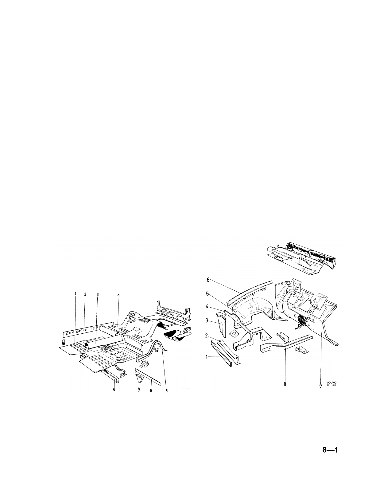
The floor and frame sections (Fig. 1) consist of a
front and rear floor plate (1 and 4) and an inner
cantrail (2), front and rear cross-members (8 and 6),
tunnel (3) and scuttle (Fig, 2). The floor plates are
welded together with the rear seat support. The
tunnel (3), which accommodates the propeller shaft
i
s spot-welded to the floor plates. The rear floor
plate has a longitudinal reinforcing member (5)
on each side at the bottom and between these a
number of cross-members. One of the cross-members (6) is provided with an attachment (7) for the
rear axle tie rod, There is a flanged hole in the rear
floor plate for mounting the fuel tank, the upper
part of which forms part of the floor in the luggage
compartment. The scuttle section (Fig. 2) consists
of the bulkhead (7), wheel arches (5), front upper
cross-member (4) and side plates (3), as well as
l
ower cross-members (1 and 2). The bulkhead forms
the front transverse wall of the body and is shaped
with welded end pieces. Two front side members
(8)
project from the front floor. At the front they
are joined together by means of a cross-member
(2) and at the rear they are connected to the front
cross-member under the front seats. Upper side
members (6) project from the upper corner between
the bulkhead and front pillar. These are spot welded to the front pillar, the front side plate and
wheel arch plates. The front axle member and
bumper support bars are attached to the side
members.
Fig. 2.
Scuttle section
Fig. 1.
Floor section (2- and 4-door)
1.
Front floor plate
2.Inner cantrail
3.
Tunnel
4.
Rear floor plate
5.
Reinforcing
member
6.
Rear cross-member
7.
Attachment for rear
8.
axle tie rod
Front cross-member
2.
Front lower
cross-member
Front lower
3.
cross-member
Side plate
4.
Front upper
5.
cross-member
Wheel arch
6.
Upper side member
7.
Bulkhead
8.
Front side member
Page 3
P 120
The front end is bolted to the upper side mem-
bers, front cross-member and front pillar. The front
mudguards are pressed in one piece and bolted
to the wheel arch plate. The front section forms
the front part of the front end as well as the air
duct to the radiator. The body is noise- and heat-
i
nsulated. The insulation consists of "waffle" board
which is stuck on to the plate.
Bonnet
The bonnet is pivoted at the rear on two hinges.
I
n the closed position, the bonnet is secured by a
bonnet lock fitted on the front section. The lever
for the bonnet lock is operated by means of a
control
placed underneath the dashboard inside
the vehicle.
Doors sand openings
The doors are built up of an outer and inner plate
together with door arch which is flanged and spot-
welded in one unit. The hinges are fitted to the
i
nner plate. The doors are adjustable both longitu-
dinally,
vertically
and laterally. The doors are
provided with a door check. This consists of a flat
bar attached to the door pillar and runs against a
roller in the door. In the open position the flat
bar obstructs the movement of the roller and thus
li
mits the movement of the door. The door checks
are fitted to the doors with screws. The pressbutton of the outside door handles operates a lever
which in turn disengages a rotating toothed roller
(tumbler). The inside door handles are fitted to the
remote control which is attached to the inner door
plate with screws. The handle transmits the movement to the toothed roller by means of a link rod.
The lock insert is fitted in the press-button on the
door handle. The doors can be locked from inside
the vehicle by pressing down the locking knobs.
The window winders are of the cable and chain
type. The movement of the window winding handle
i
s transmitted to the window itself by a cable and
chain which are joined together forming an endless
"drive
This is mounted on two pulleys and a
sprocket. The lower pulley is provided with a spring
device for tensioning.
The luggage compartment lid is built up of an outer
and inner plate. The catch for the locking device
i
s fitted on the lower edge of the luggage compartment lid. The hinges are fitted at the upper edge
of the lid. The hinges are bolted to the plate under
the rear window through a reinforcing plate. The
Fig. 4.
Roof section (2- and 4-door)
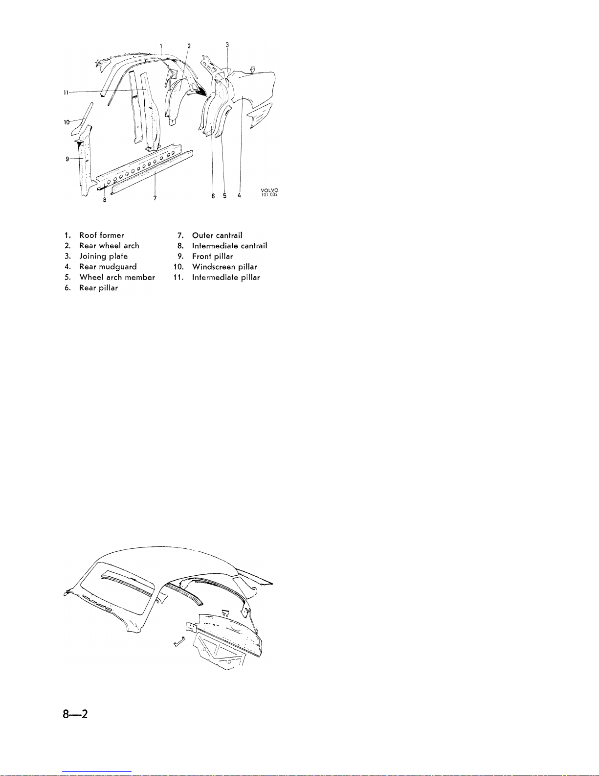
On 4-door models the side section (Fig. 3)
consists of the front pillar (9), intermediate pillar (11),
rear pillar (6), intermediate and outer cantrails (8
and 7), roof former (1), windscreen pillar (10), rear
wheel arch (2) with wheel arch member (5), rear
mudguard (4), back plate and joining plate (3). The
cantrail and wheel arch member are manufactured
of galvanized sheet metal.
The roof section (Fig. 4) consists of a number of
pressed steel plates. The roof plates form the
upper part of the scuttle section, windscreen openi
ng, the roof itself, the opening for the rear window
and the upper limit of the luggage compartment.
The front mudguards, front section and bonnet
make up the front end.
Fig. 3.
Side section (4-door)
Page 4
l
uggage compartment lid is counter-balanced with
torsion rods and can be set in any position when
opening. On chassis up to number 20999, the lock-
i
ng device is placed on the body below the lid,
and on vehicles with effect from chassis number
21000, the locking device is fitted on the lid.
Interior fittings and upholstery
FRONT SEATS, LATE PRODUCTION
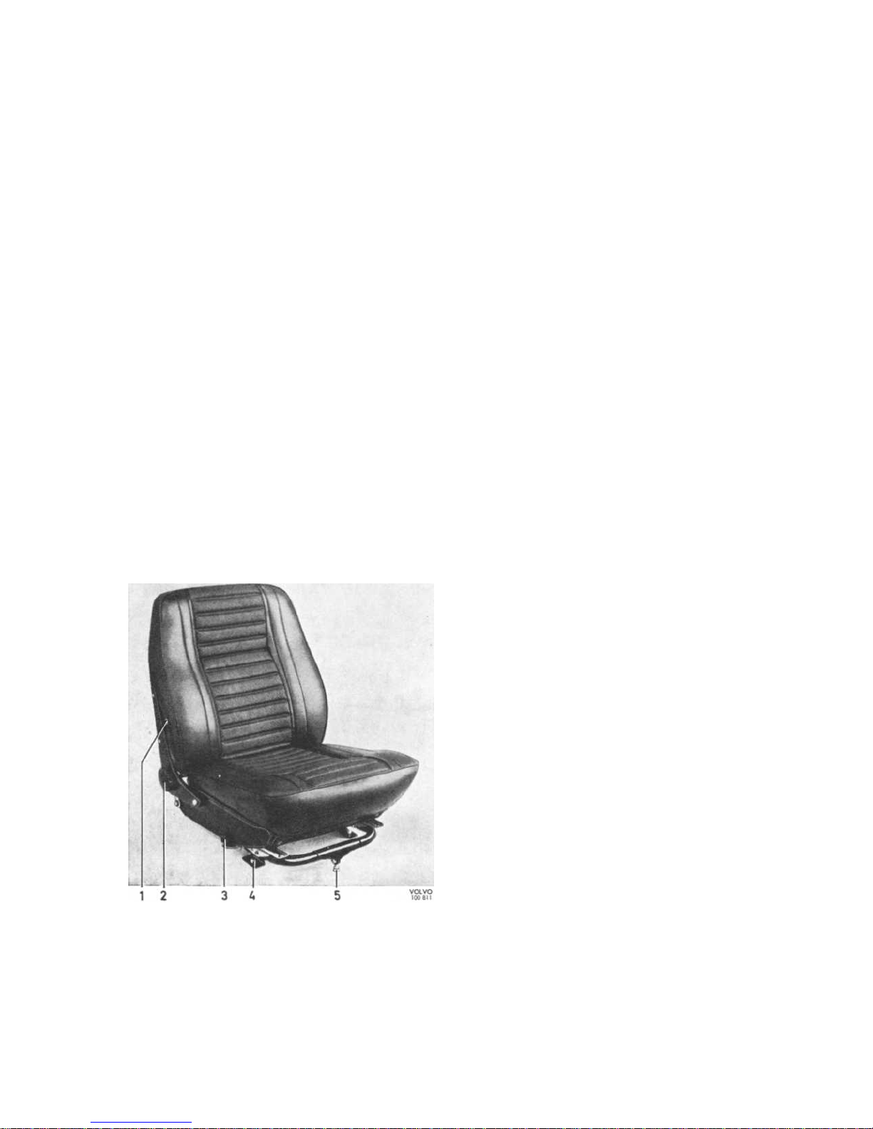
The front seats are built up on a tubular frame. The
padding consists of foam plastic which is covered
by fabric-backed vinyl. The seat can be adjusted
l
ongitudinally by releasing the catch (3, Fig. 5), and
sliding the seat. The seat can be adjusted vertically
at the attachment (4) which is provided with holes
at different heights. The seat can be tilted to the
desired position by means of the adjusting device
(5).
The backrest inclination is variably adjustable
by means of the handwheel (2) which operates an
eccentric. The seat is provided with an adjustable
l
umbar support (see Fig. 7), the tension of which
Bild 5.
Front seat (4-door)
1.
Adjustment of lumbar support
2.
Adjustment of backrest inclination
3.
Longitudinal adjustment
4.
Adjustment of seat height
5.
Adjustment of seat inclination
P 120
i
s
adjusted with a screw (1, Fig. 5 and 3, Fig. 7)
on each side of the backrest. The seat cushions are
attached to the seat frame by means of pressfasteners.
REAR SEAT
The rear seat and backrest are built up in principle
i
n the same way as the front seats, although in this
case the seat frame consists of a wooden frame.
DOOR UPHOLSTERY
The door upholstery consists of wood-fibre sheeting
lined
with non-woven padding and covered with
upholstery material. It is secured to the door by
means of clips. The front armrest is made of moulded plastic and is screwed to the inner plate of the
door.
HEADLINING
The headlining consists of plastic material stretched
on roof ribs and secured in retainers fitted on the
upper limit of the body sides.
COVERING FOR BULKHEAD AND FLOOR
The sides of the bulkhead are lined with millboard
which is attached with clips. The bulkhead is
covered with plastic-lined felt matting. The floor is
covered with rubber mats.
Bumpers
The bumpers are composed of three parts and the
upper joints are provided with overriders. The bum-
pers are fitted on four support bars, of which the
front ones are attached to the front side members
and the rear ones to the rear side members.
8-3
Page 5
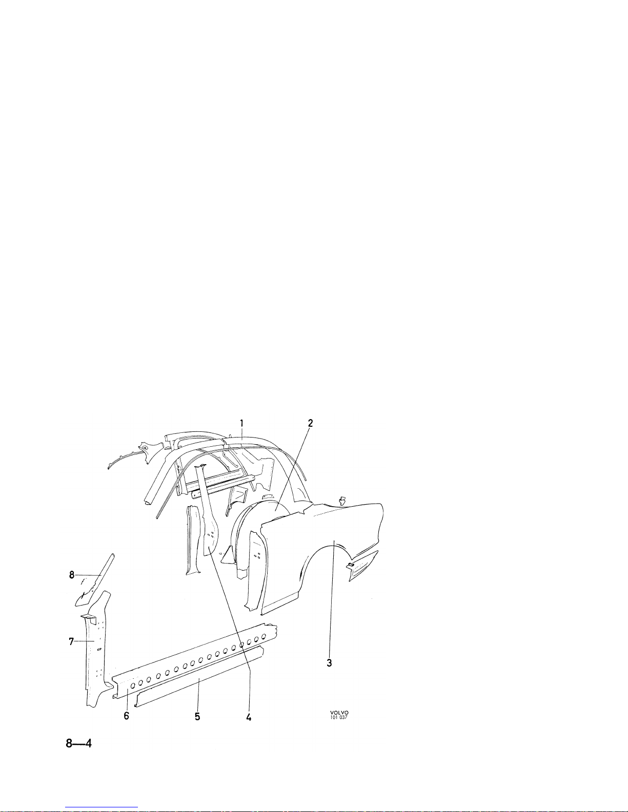
P120
P 120,2-DOOR
Body frame
The body frame is largely similar to that of the
4-door model. However, the side part is altered
so that there is no longer an intermediate pillar
and the rear mudguard (3, Fig. 6) is extended. The
side section consists of front and rear door pillars
(7 and 4), intermediate and outer cantrails (6 and
5), roof former (1), windscreen pillar (8), rear wheel
arch (2) and rear mudguard (3).
Bonnet
See the 4-door model.
Doors and openings
See the 4-door model.
Interior fittings and upholstery
FRONT SEATS
The front seats on the 2-door vehicle can be
hinged forwards in order to facilitate entry to the
rear seats. They are provided with catches (4) in
order to prevent tilting forwards (see Fig, 7).
OTHER INTERIOR FITTINGS
Concerning other fittings and the bumpers, see the
4-door model.
P 120 STATION WAGON
Body frame
The front end is the same as that on the 2-door and
4-door models, The floor section (Fig. 8) consists of
the front (11), intermediate (3) and rear (4) floor
plates, tunnel, inner cantrail (1), side members (6),
front (10), intermediate (8) and rear (5) cross-mem-
bers.
The front and intermediate floor plates are welded
together at the rear seat support. The tunnel is
spot-welded to the front floor plate (11). Two rear
side members (6) are welded to the lower side of
the intermediate (3) and rear (4) floor plates, one
on each side, and between these a number of
cross-members.
One of the cross-members (8) is
provided with an attachment (9) for the rear axle
tie rod. Both the rear side members are provided
with attachments for the rear axle support arms.
The spare wheel well (7), which is provided with
a lid in the floor, is welded on the lower side of
the rear floor plate. There is a flanged hole in this
for the fuel tank.
Fig. 6.
Side section (2-door)
1.
Roof former
2.
Rear wheel arch
3.
Rear mudguard
4.
Rear pillar
5.
Outer cant rail
6.Intermediate cant rail
7.
Front pillar
8.
Windscreen pillar
Page 6
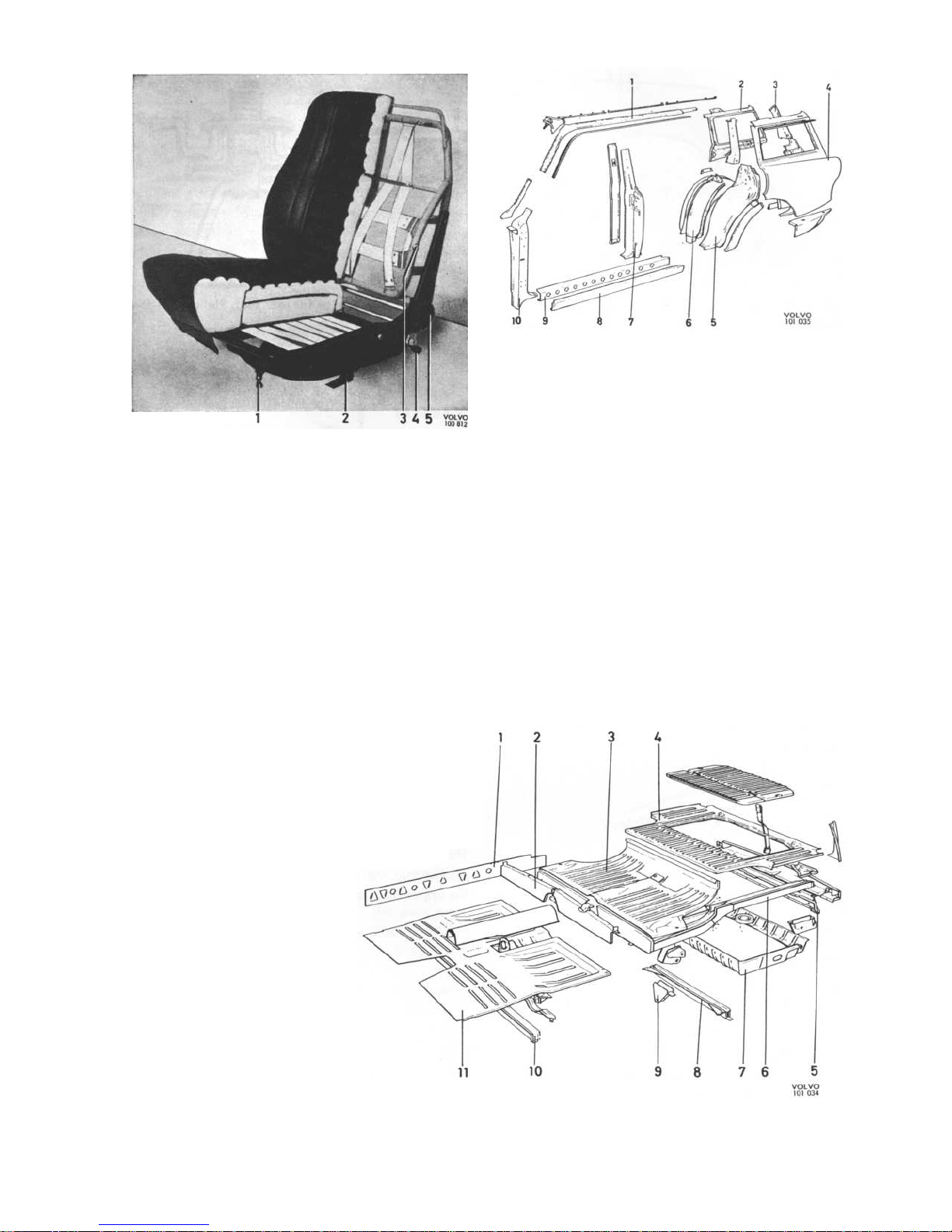
P 120
Fig. 9.
Side section, Station Wagon
1.
Roof former
2.Inner frame for side
window
3.
Upper rear pillar
4.
Rear mudguard
5.
Rear intermediate
pillar
6.
Rear wheel arch
7.
Front intermediate
pillar
8.
Outer cantrail
9.
I
ntermediate cantrail
10.
Front pillar
Fig. 7.
Front seat (2-door)
1.
Adjustment of seat inclination
2.
Adjustment of seat height
3.
Adjustment of lumbar support
4.
Longitudinal adjustment of seat
5.
Adjustment of backrest inclination
The scuttle section is similar to that on the 2- and
4-door models.
The side section (Fig. 9) consists of the front pillar
(10), intermediate pillar (7), rear section, interme-
diate (9) and outer (8) cantrails, inner and outer
roof formers (1) and windscreen pillar. The rear
section is composed of the rear wheel arch (6), rear
mudguard (4), inner frame (2) for rear side window
and upper (3) and lower rear pillar. The upper part
of the rear mudguard is extended upwards and
forms the outer frame for the rear side window.
Fig. 8.
Floor section,
Station
Wagon
1. I
nner cantrail
2.
Rear seat support
3. I
ntermediate floor plate
4.
Rear floor plate
5.
Cross-member
6.
Side member
7.
Spare wheel well
8.
Cross-member
9.
Attachment for rear axle
support arms
10.
Cross-member
11.
Front floor plate
8-S
Page 7
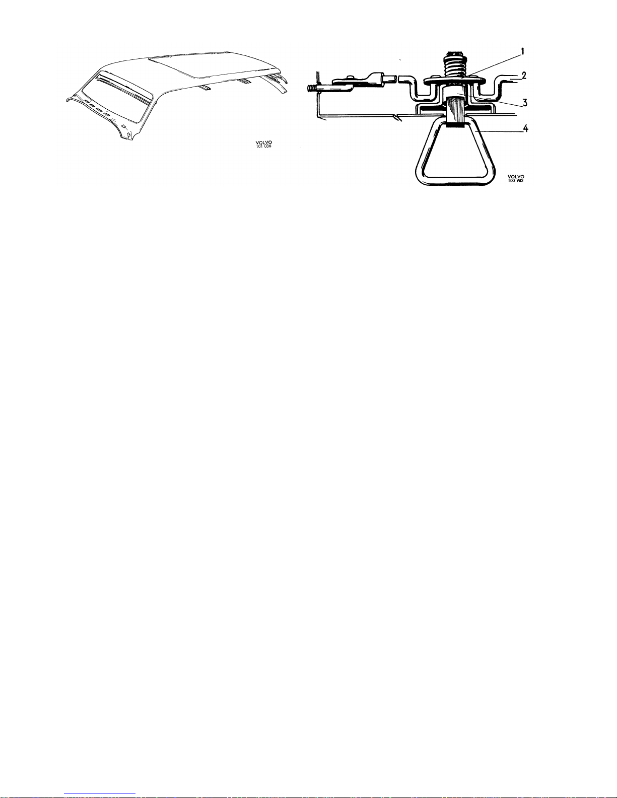
P 120
Fig. 10.
Roof section, Station Wagon
Fig. 11.
Catch device for rear seat, Station Wagon
1.
Eccentric
2.
Pull rods
3.
Catch sleeve
4.
Handle
The roof section (Fig. 10) consists of the roof
plate,
windscreen member, two roof arches and
rear member.
Doors and openings
The doors on the Station Wagon are similar to those
on the 4-door model. The tailgate consists of an
upper and lower part. The hinges of the upper
tailgate are attached to the rear edge of the roof
section and those of the lower tailgate are bolted
i
n the rear cross-member. The inside of the lower
tailgate is provided with a cover plate and mat
which are attached by means of screws. Both tail-
gate sections are locked by means of a common
l
ock which is bolted on to the lower tailgate. Each
of the tailgate sections is provided with a support
for holding it in the open position. Opening of the
upper tailgate is facilitated by means of a gas
spring, i.e. a piston which runs in an enclosed gasfilled
cylinder. There are four different opening
positions.
Interior fittings and upholstery
FRONT SEATS
See the corresponding section for the 4-door
model.
REAR SEAT
The rear seat is built up of springs on a frame and
has foam plastic padding which is covered with
vinyl. The seat cushion is provided with two hinges
at the lower front edge and can if necessary be
tipped up against the front seats. It is covered with
a
mat underneath and forms the front limit of the
l
oading space when in the tipped-up position.
The backrest consists of a back plate fitted with
rubber bands. The padding consists of foam plastic
and the upholstery of fabric-backed vinyl. The rear
side of the back plate is provided with a mat and
when folded down forms an extension of the floor
i
n the loading space. The backrest is locked in the
normal position by a spring-loaded catch device,
see Fig. 11, the handle (4) of which operates the
l
atches through an eccentric (1) and pull rods (2).
The lower corners of the backrest rest partly on a
fixed catch and partly (on the left-hand side) on a
sprung catch.
Bumpers
The bumpers are the same as on the 4-door model
except that the rear overriders serve as footsteps,
the upper sides of which are rubber-covered.
Page 8
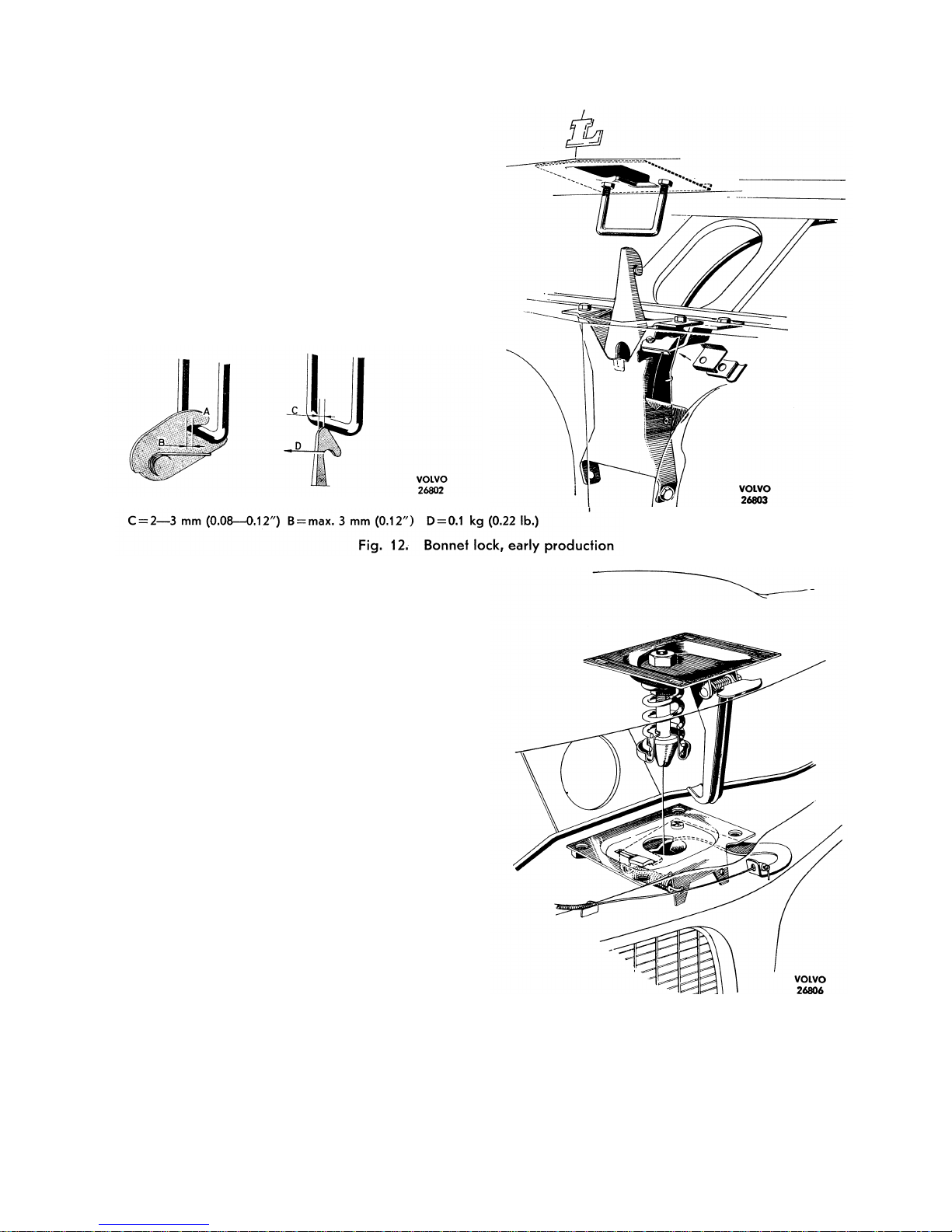
P 120
REPAIR INSTRUCTIONS
FRONT END
Front mudguards
The front mudguard is removed by taking out the
following screws: the screw between the mudguard
and stay at the lower side member, the screw bet-
ween the mudguard and body side behind the
above-mentioned stay, the screws in the front side
section and the screws in the upper side member.
I
n addition, the headlamp with leads must be removed. Concerning removing the headlamp, see
Part 3. Fitting is done in the reverse order.
Front section
The front section is attached to the front mudguards,
wheel arch plates and the upper and lower crossmembers.
When removing, take out the headlamps, the screws
between the front section and splash guard under
the headlamp, the screws in the upper and lower
cross-members and the screws in the wheel arch
plates.
Bonnet and bonnet lock
The bonnet is attached by means of screws in each
hinge. The bonnet is removed by taking out the
screws between the hinges and bonnet. The hinges
are attached to the body with four screws each.
All the holes in the hinges are oval in order to
permit the bonnet to be adjusted.
There are two types of bonnet lock. The early production lock (up to chassis number about 10 000)
i
s illustrated in Fig. 12. The bonnet lock is adjusted
as follows.
When the bonnet is locked the U-shaped catch
should lie right inside the lock catch groove and
the measurement B, Fig. 12 must not exceed 3 mm
(0.12").
Any adjustment should be made on the
catch itself. It should be adjusted vertically so that
the gap between the bonnet and the front section
Fig. 13.
Bonnet lock, late production
of the body is 4.5 ± 1 mm (0.18 ± 0.04"). The tension
of the safety catch spring should be at least 0.1 kg
(0.22 lb.) measured at D, Fig. 12, in order to move
it from its rest position.
8--
7
Page 9
P 120
8-8
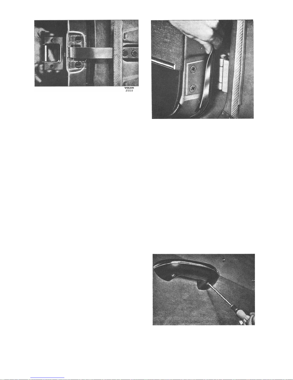
Fig. 14.
Door check
When the bonnet is closed, the U-shaped catch
should meet the safety catch as close to the top as
possible, but not so high as to cause the hook
to be pushed forwards, measurement C, Fig. 12.
A small adjustment of 1-2 mm (0.04-0.08") can
be made by bending the safety catch. If a larger
adjustment is found to be necessary, this means
that the whole locking device has been displaced.
I
n this case the complete bonnet lock must be reset.
The late production lock, with effect from chassis
number about 10000, is illustrated in Fig. 13.
The lock can be adjusted laterally and longitudinal-
l
y since the
holes in the front section are larger than
the diameter of the attaching screws. The length
of the latch is adjustable by means of nuts. The
l
atch and spring are lubricated with grease.
DOORS
Removing front door
1.
Remove the door check, see Fig. 14. The
attaching bolts for this are accessible after
the side insulation material on the body has
been removed. The door check can also be
removed by unscrewing the guide roller and
pulling it off. In order to get at the guide
roller, the door upholstery must be removed
see under "Removing the door handle and
upholstery".
2.
Unscrew the four countersunk screws which
hold the door to the upper and lower hinges.
The door sealing strip must be moved in order
to get at the hinge screws. This is done by
releasing the two plates over the hinges
to which the strip is glued and carefully pulling
to one side, see Fig. 15. When doing this,
make sure that the rubber strip does not come
away from the plate or door.
Fig. 16.
Removing armrest
VOLVO
25255
Fig. 15.
Plate over hinge
Fitting the door is done in the reverse order
to removing. Since the holes in the door are
l
arger than the diameter of the bolt, and the
nut plates are movable, the hinge attachment
can be adjusted both vertically and laterally.
The door is adjusted longitudinally at the
hinge attachments in the body.
Removing rear door
(See also under "Removing front door")
1.
Remove the door check. The attaching bolt
for this is accessible after the rubber plug in
the centre pillar has been removed.
2.
Remove the plates over the hinges.
VOLVO
23235
Page 10
P 120
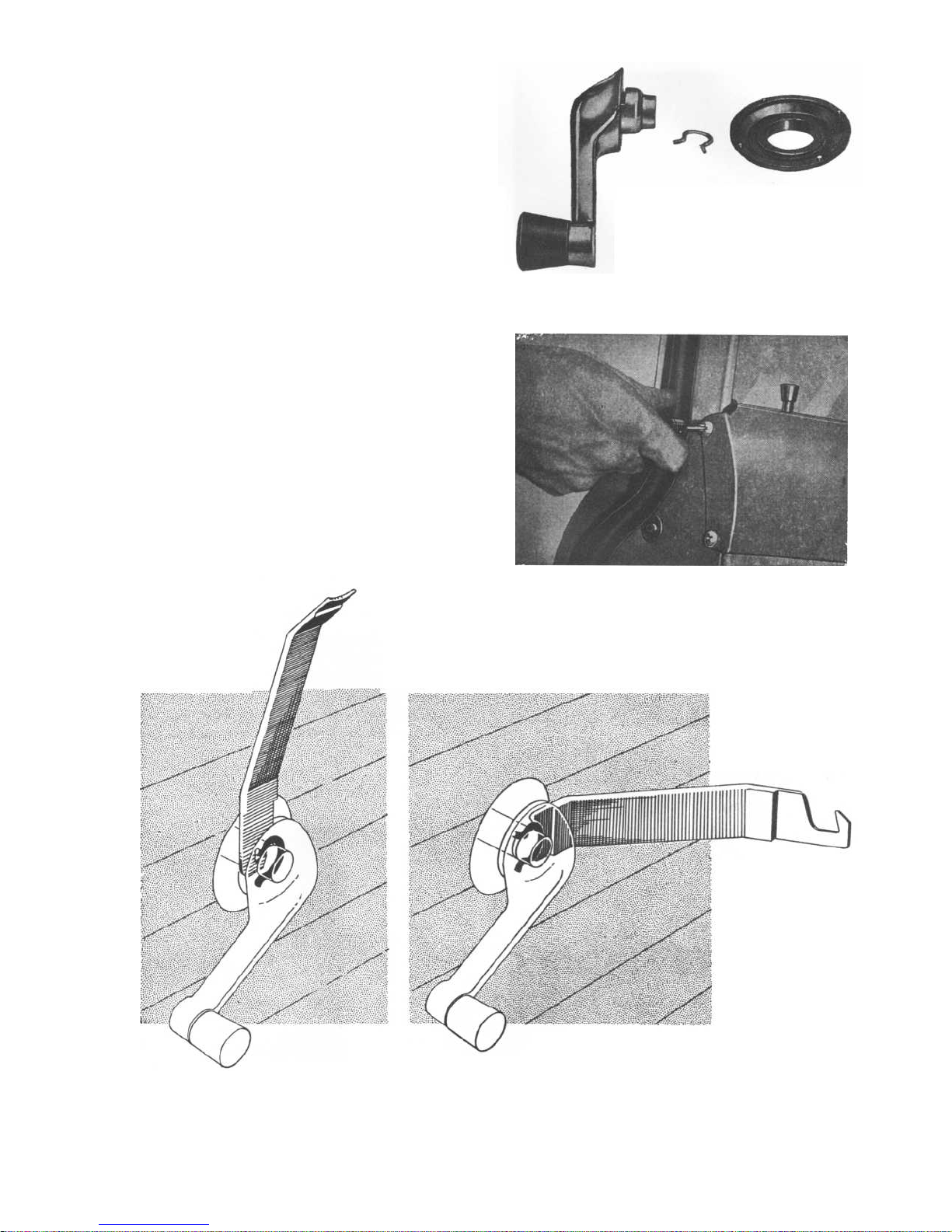
Fig. 18.
Window winder with circlip
3.
Remove the screws in the hinges and lift off
the door.
The holes in the centre pillar are larger than
the diameter of the bolts. When running nuts
are used, this enables the door to be adjusted
both vertically and laterally.
Removing door handle and upholstery
1.
Remove the armrest, which is attached with two
screws accessible from underneath the armrest,
see Fig. 16.
2.
Remove the door handle and window winding
handle. These are removed by prising out the
l
ocking washer which holds them with tool
SVO 2297,
see Fig.
1
7.
The window winder,
l
ocking washer and circlip are illustrated in
Fig. 18.
3.
Remove the upper trim moulding. This is
attached to the door edges by four screws,
see Fig. 19.
Fig. 19.
Removing the upper trim moulding
Fig. 17.
Removing and fitting the window winder
Page 11
P 120
8-10
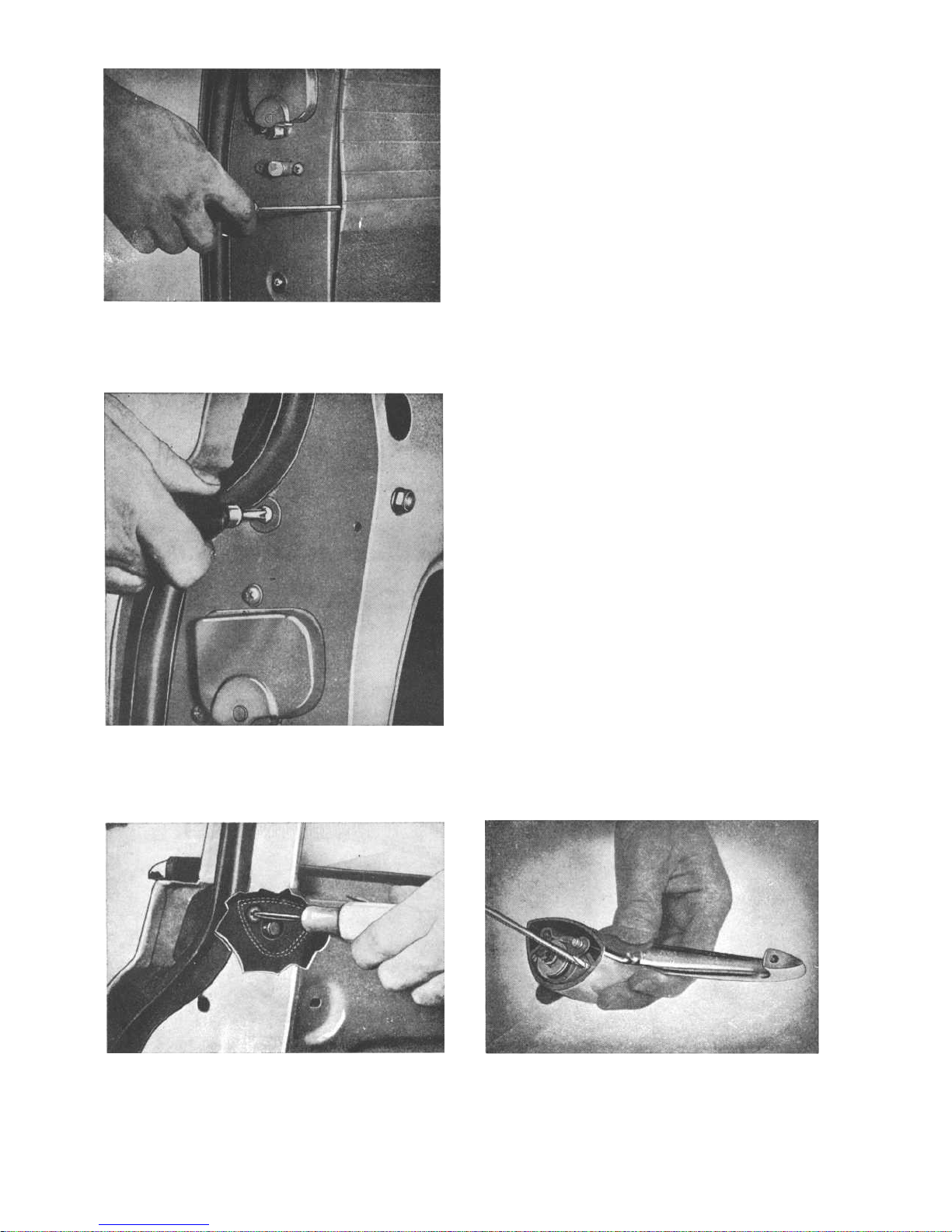
Fig. 22.
Removing the lock handle
VOLVO
23210
Fig. 20. Removing the door upholstery
VOLVO
23211
Fig. 21.
Removing upper screw for guide rail
VOLVO
23256
4.
Remove the door upholstery by carefully app-
l
ying a screwdriver or similar under the padded edge and then prising outwards, when
the upholstery will come away, see Fig. 20.
5.
Remove the paper protectors which are fitted
over the holes in the inner plate of the door.
Door locks and door handles
REMOVING DOOR LOCKS AND LOCK HANDLES
Carry out operations 1-5 under "Removing the
door upholstery".
1.
Unscrew the two screws which hold the guide
rail for the window. The screws are accessible
from the edge of the door as shown in Fig.
21.
Lift out the guide rail.
2.
Unscrew the three screws which hold the inner
handle mechanism (remote control).
3.
Lift
off the link arm between the lock knob
roller
mechanism and disconnect the link for
the outer handle from the roller mechanism.
4.
Unscrew the four screws on the edge of the
door which hold the toothed roller mecha-
nism.
5.
Lift off the door with remote control.
6.
The door handle is removed by unscrewing the
t
wo screws which hold it, see Fig. 22. The
screws are accessible from the inside of the
door and are most easily removed after the
window has been let down or taken out, see
under "Window winder with mechanism".
Fig. 23. Dismantling the lock handle
VOLVO
23212
Page 12
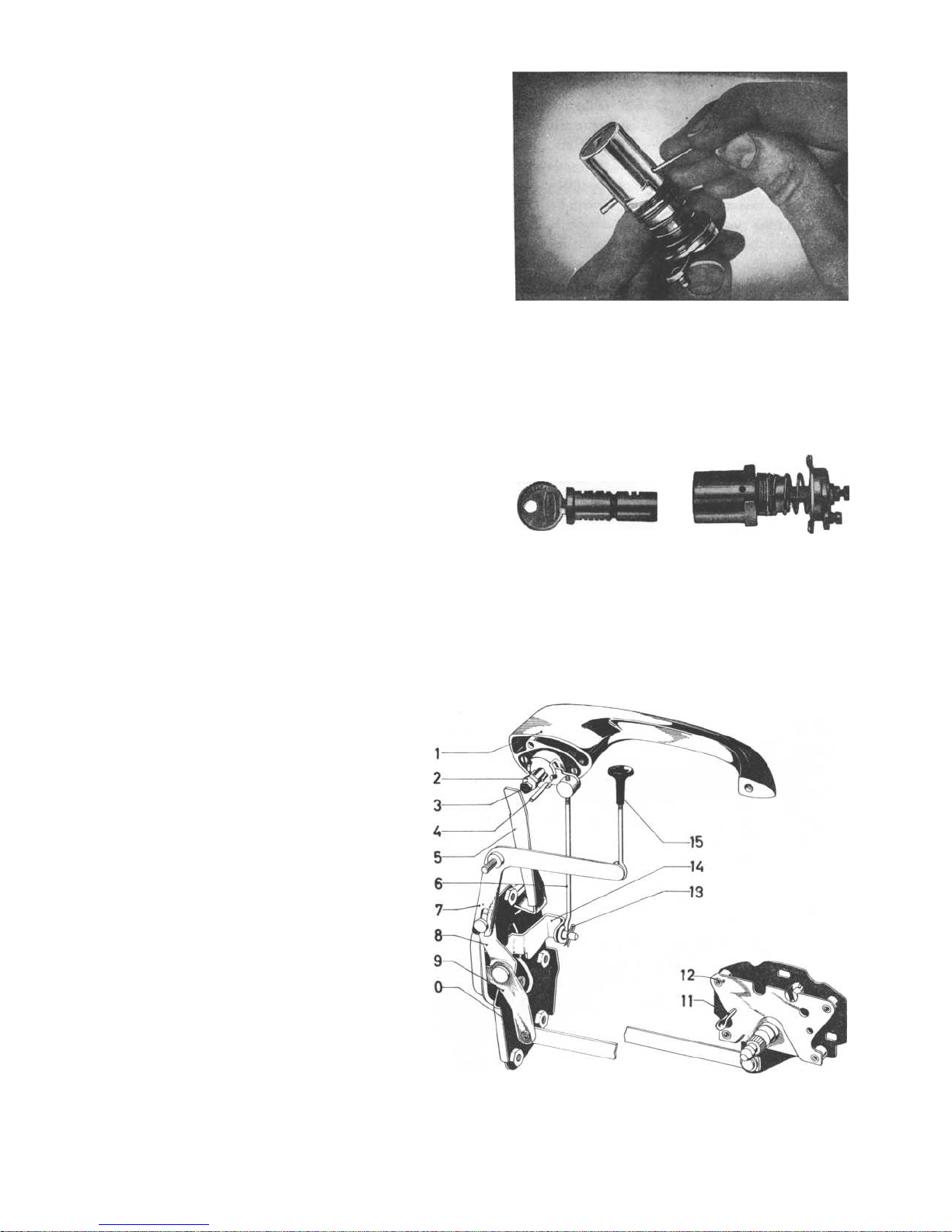
DISMANTLING THE DOOR HANDLES
1.
Unscrew the two screws which hold the pressbutton and lock plunger to the door handle,
see Fig. 23.
2.
Press out the locking pins as shown in Fig. 24.
3.
Turn the key backwards and forwards a few
ti
mes in the press-button at the same time as
pulling outwards, when the lock plunger will
release and can be pulled out as shown in
Fig. 25.
FITTING AND ADJUSTING THE LOCKS
Front door
1.
Fit the lock (10, Fig. 26) with remote control
(12) in the door without tightening the screws.
2.
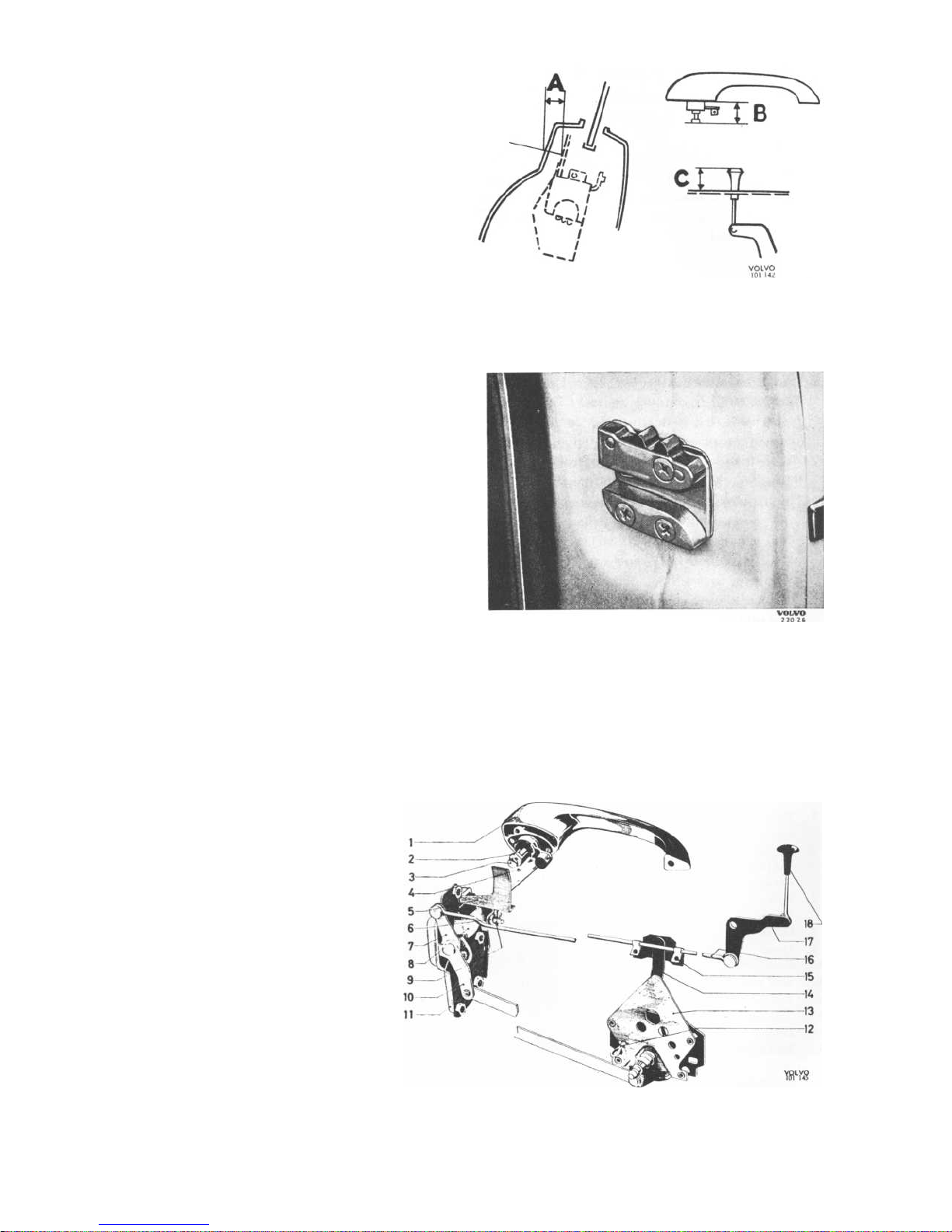
Adjust measurement A, Fig. 28 to 15±0.5 mm
(0.59 ± 0.02") by turning the lock. Tighten the
l
ock hard. If it is not possible to obtain the
correct measurement for A by turning the lock
after it has been tightened up as near to A as
possible, the remaining adjustment is done
by bending the lever (5). Measurement A must
be checked within the specified tolerances.
3.
The remote control (12) with split pin (11)
fitted is pushed backwards so that the lever
(9) stops against the lock (10). The remote
control is screwed on in this position. Remove
the split pin (11).
4.
Fit the lever (7) for the inner locking knob (15).
Fig. 26.
Adjusting the front door lock
1.
Outer handle
2.
Lock nut
3.
Adjusting screw
4.
Pin (for checking)
5.
Lever
6.
Link
7.
Lever.
8.
Lever
9.
Lever
10.Lock
11.
Split pin
12.
Remote control
13.
Locking spring
14.
Lever
15.
Locking knob
VOLVO
23244
Fig. 25.
Press-button dismantled
P 120
VOLVO
23243
Fig. 24.
Pressing out the locking pin
VOLVO
1
01 44
8-11
Page 13
P 120
Rear door
1.
Fit the lock (11, Fig. 27) with remote control
(13) in the door without tightening the screws.
2.
Adjust measurement A, Fig. 28 to 17±0.5 mm
(0.67 ± 0.02") by turning the lock. Tighten the
l
ock hard. If it is not possible to obtain the
correct measurement for A by turning the lock
after it has been tightened up as near to A as
possible, the remaining adjustment is done by
bending the lever (5). Measurement A must be
checked within the specified tolerances.
3.
The remote control (13) with split pin (12)
fitted is pushed backwards so that the lever
(10) stops against the lock (11). The remote
control is screwed on in this position. Remove
the split pin (12).
4.
Fit the lever (17) and connect the link (16)
to the lever (1).
5.
Set the lever (7) in the locked position, i.e.
backwards against the lock and lever (14) in
the rear catch position. Check through the
control hole (12) that the lever moves fully
to the catch position. In this position the lever
(14) is locked to the link (16) with screws at
the clips (15). Check that the link (16) does
not rub against the inner plate of the door.
On the other hand it must not be bent out so
much that it rubs against the screws of the
i
nner trim moulding.
Fig. 27.
Adjusting the rear door lock
1.
Outer handle
2.
Locknut
3.
Adjusting screw
4.
Pin (for checking)
5.
Lever
6.
Link
7.
Lever
8.
Lever
9.
Locking spring
10.
Lever
11.
Lock
12.
Split pin
13.
Remote control
14.
Lever
15.
Clip
16.
Link
17.
Lever
18.
Locking knob
8-12
Fig. 29.
Striker block
'
Fig. 28.
Adjusting measurements for lock
Page 14
FITTING AND ADJUSTING THE OUTER HANDLES
Front door, early production
1.
Check that measurement B, Fig. 28=15± 1 mm
(0.59±0.04"). Adjust if necessary. Tighten the
l
ocknut (2) on the screw (3), Fig. 26.
2.
Fit the outer handle (1) with link (6) fitted on.
3.
Connect the link (6) to the lever (14). Adjustment is done by selecting one of the three
holes so that the recess and hole in the outer
handle coincide. This is done by inserting a
pin (4) into the hole in the outer handle as
shown in the figure. They should come in
line
when the locking knob (15) is pressed
down, i.e. the lever (7) is pressed down and
the lever (8) moved backwards against the
l
ock.
Late production
1.
Check that the measurement B, Fig. 28=
1
5±
1
mm (0.59 ± 0.04"). Adjust if necessary.
Tighten the locknut (2) on the screw (3), Fig.
26.
2.
Fit the outer handle (1) with link (6) fitted on.
3.
Connect the link (6) with the lever (14). The
l
ever in the handle is set in such a position
that a pin (4) (3 mm=0.12") can be inserted
i
n the hole in the handle. Adjusting is done
by screwing the link up or down so that the
l
oop of the link (6) comes in line with the
l
ever (14) on the lock.
Rear door
Late production
1.
Check that the measurement B, Fig. 28= 15±
1
mm
(0.59±0.04").
Adjust if necessary.
Tighten the locknut (2) on the screw (3), Fig.
27.
2.
Fit the outer handle (1) with link (6) fitted on.
3.
Connect the link (6) with the lever (8). The
l
ever in the handle is set in such a position
that a pin (4) (3 mm=0.12") can be inserted
i
n the hole in the handle. Adjusting is done
by screwing the link up or down so that the
l
oop of the link (6) comes in line with the
l
ever (8) on the lock.
P 120
Inner locking knob
With the locking knob in the pressed-down position,
measurement C, Fig. 28 should be 12± 1 mm
(0.47 ± 0.04") for both the front and rear door.
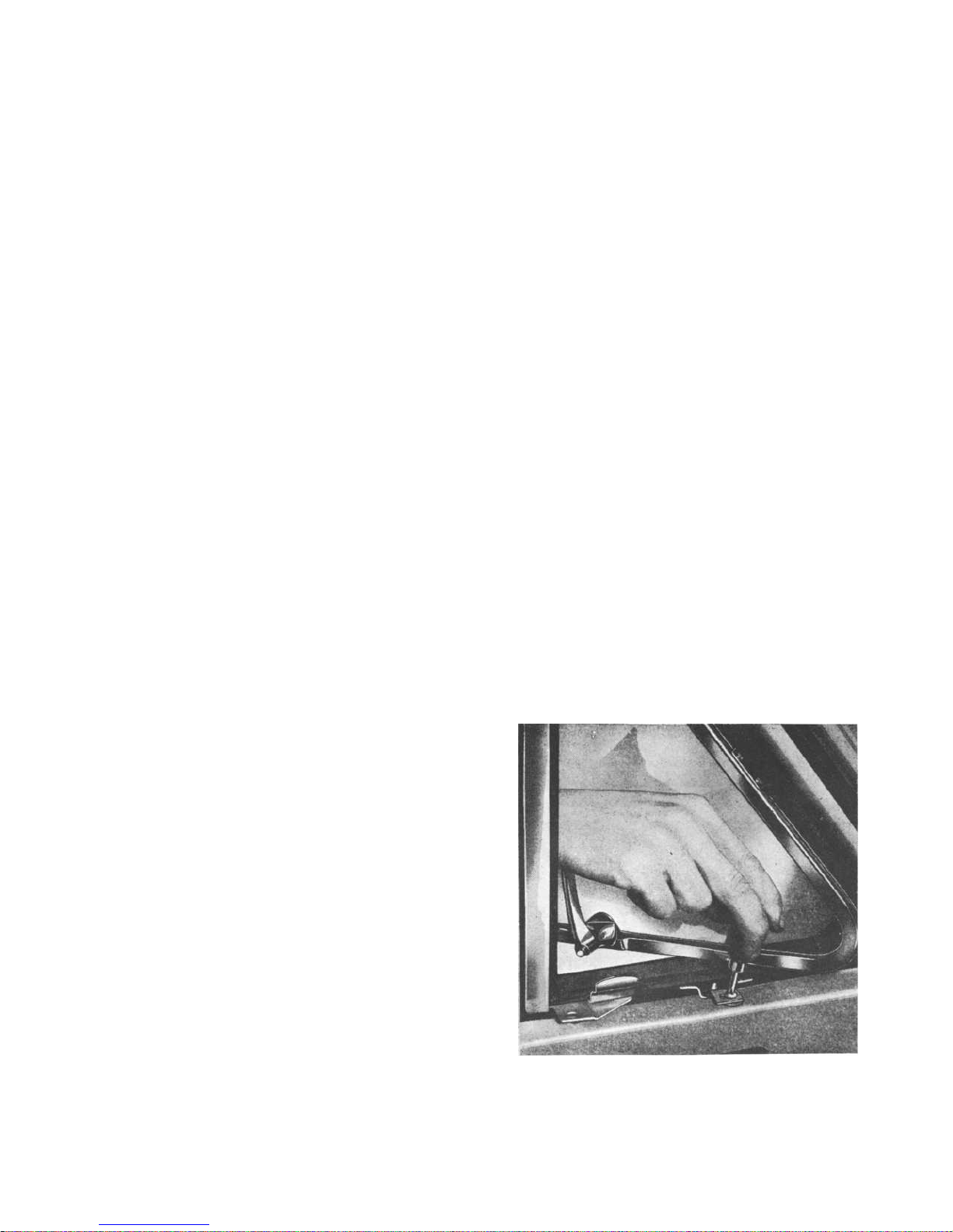
STRIKER BLOCK
The striker block (Fig. 29) is made of steel and
fitted
with
a floating nut plate. The block is
adjustable since the holes in the body have a
l
arger diameter than that of the attaching screws.
The vertical position of the striker block is checked
by closing the door with the press-button of the
outer handle pressed in, when the dowel pin should
slide correctly into the striker block. N.B. This should
be done immediately after the striker block has
been fitted.
Ventilation windows
REMOVING AND FITTING
The ventilation window is built in with one of the
guide rails for the winding window. A suitable procedure for removing the ventilation window with
sealing strips is as follows:
1.
Carry out operations 1-
5 under "Removing
the door upholstery".
2.
Unscrew the five screws which hold the window to the door and door arch, see Figs. 30
and 31.
VOLVO
1
01 040
Fig. 30.
Attaching screw for ventilation window
8
1
3
Page 15
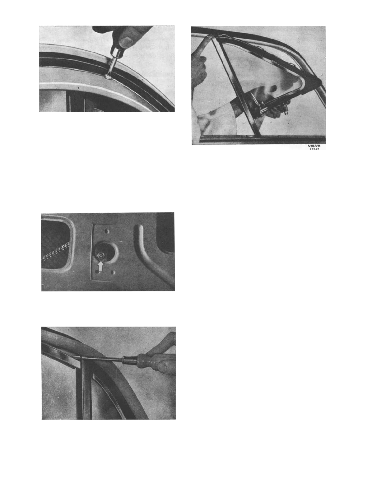
P 120
8-
1
4
Fig. 31.
Upper attaching screw for ventilation
window
3.
Unscrew the screws which hold the guide rail
for the winding window, see Fig. 32. This only
applies to the extended guide rail on the front
doors.
4.
Remove the upper guide strip with a screw-
driver as shown in Fig. 33.
5.
Lift up the window as shown in Fig. 34.
Fig. 33. Removing upper guide strip
VOLVO
1
01 039
VOLVO
23250
Fig. 32.
Attaching screw for winding window
guide rail
VOLVO
23246
Fig. 34.
Lifting out the ventilation window
Window winder with mechanism
REMOVING AND FITTING
Carry out operations 1-5 under "Removing the
door upholstery".
Carry out operations 1-5 under "Ventilation windows, removing and fitting".
1.
Remove the clip which holds the carrier on the
winding cable to the rail under the window
and lift it up as shown in Fig. 35. On the rear
doors there is no carrier and the clip fits
directly on the winding chain.
2.
Release the cable tensioning device by
slackening the nut for the catch screw on the
l
ower pulley. Lift off the cable and chain.
3.
If
necessary remove the upper pulley, lower
pulley
with tensioning device and winding
sprocket itself. The winding sprocket is removed by unscrewing the four screws, Fig. 36,
after which the sprocket with shaft is lifted out.
Before fitting the winding window, make sure
that the guide strips and seals are in good
condition.
Worn or
,
damaged parts must be
replaced.
The cable for the winding mechanism should
be tensioned well but not too hard. Lubricate
the cable and chain with grease and the pulley
and winding sprocket with oil.
After fitting, check that the window runs easily
i
n the guide rails.
Page 16
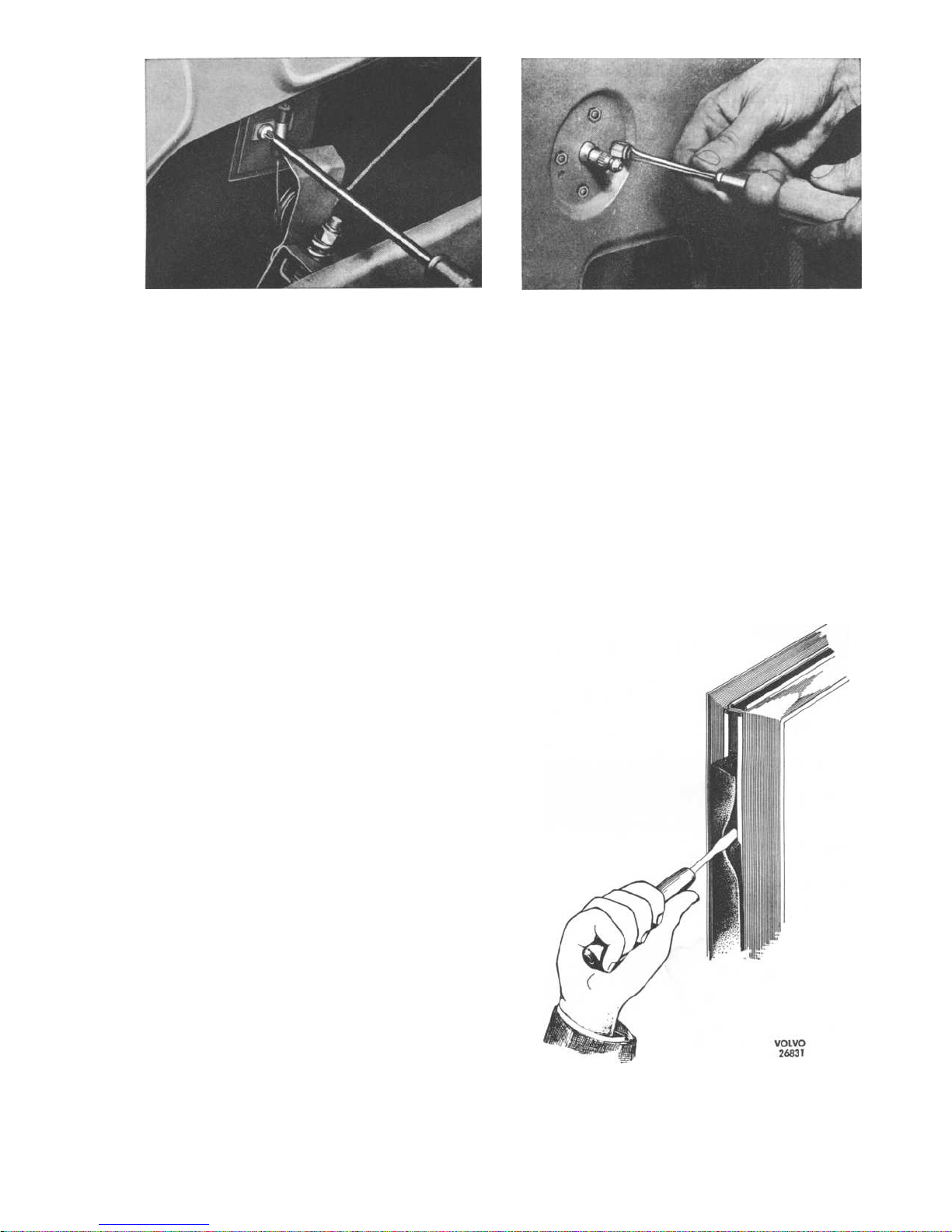
VOLVO
23248
Fig. 35.
Removing clip for carrier
Sealing strips
A.
BONDED STRIPS
The following procedure is recommended when fitti
ng new rubber strips:
1.
Remove the old strips.
2.
All traces of old adhesive should be care-
fully removed from the metal surfaces with
petrol or similar. It is most important to carry
this
out carefully since no residue from old
adhesive must be left on the metal, but at the
same time care must be taken to make sure
that the paintwork is not damaged by the
solvent
used.
(Requirements:
clean
rags,
wooden putty knife).
3.
The new rubber strips should be thoroughly
cleaned with petrol, methylated spirit or simil
ar. (Requirements: clean rags, fibre brush).
4.
After they have dried, the rubber strips should
be
coated with Dekalin TH or equivalent and
then allowed to dry to a non-tacky state, which
usually takes about 15 minutes. (Requirements:
thick hair brush).
5.
The metal surfaces to which the rubber strips
are to be attached are then coated with
Dekalin TH. (Requirements: thick hair brush).
6.
The treated and non-tacky rubber strips are
then pressed on to the newly-coated adhesive
on the metal.
7.
The rubber strips should be pressed firmly
against the metal surfaces so that there is no
air trapped in the joints.
N.B.
Wait for at least 15 minutes after the strips
have been applied before closing the door.
P 120
VOLVO
23249
Fig. 36.
Removing sprocket
B.
STRIPS ATTACHED WITH FASTENING RAIL
On late production vehicles the sealing strip is
attached by means of a fastening rail which is spotwelded to the door.
The sealing strip is removed by pulling it outwards,
when the ridge of the strip releases from the rail.
When fitting the sealing strip, one of the ridges is
placed in position in the rail, after which the other
ridge is pressed down into the rail with the help
of a screwdriver. This is moved along the rail as
shown in Fig. 37.
Fig. 37.
Fitting sealing strip for door
8-15
Page 17
P 120
Luggage compartment lid, 2- and
4-door models
The luggage compartment lid is mounted on two
hinges, both of which are attached by means of
three screws to the inner plate of the lid and with
t
wo screws to the plate under the rear window.
The holes in the part of the hinges fitted in the lid
are oval so as to permit longitudinal adjustment. In
order to obtain lateral adjustment the holes in the
body under the rear window are made larger than
the diameter of the screws. These screws are accessi
ble after the insulating material round the edge of
the rear window has been removed.
When removing the luggage compartment lid, tension
must first be removed from the torsion rods
which support the lid.
Apply tool
SVO 2572
as shown in Fig.
38
and prise
down the loop on the torsion rod until the catch
releases.
Move aside the catch and let the torsion
rod move back. Remove the torsion rod attachment
i
n the body. The other end of the tool is used as
shown in Fig.
39.
Prise upwards with the tool so
that the bent part of the torsion rod slides out of
the groove. Hold the tool in this position and grasp
the middle of the torsion rod with one hand and
pull it outwards as shown in Fig.
39
so that it
releases from the bracket when the tool is moved
back and the torsion rod is relieved of tension.
The locking device on vehicles with chassis num-
bers lower then
21000
isattached with two screws
and a circlip on the body under the luggage
compartment lid. The locking device is released
by pressing in the lockable press button. The locki
ng clamp on the lower edge of the luggage compartment lid is adjustable in order to permit variation
of the tightness with which the lid can be
l
ocked.
When removing the lock, the two screws at the
edge of the luggage compartment opening in the
body are removed as well as the circlip round the
l
ock press-button, see Fig. 40.
When fitting, the
circlip is first fitted and then the screws. Make sure
that the rubber washer round the lock button seals
properly.
The locking device on vehicles with effect from
chassis
21000
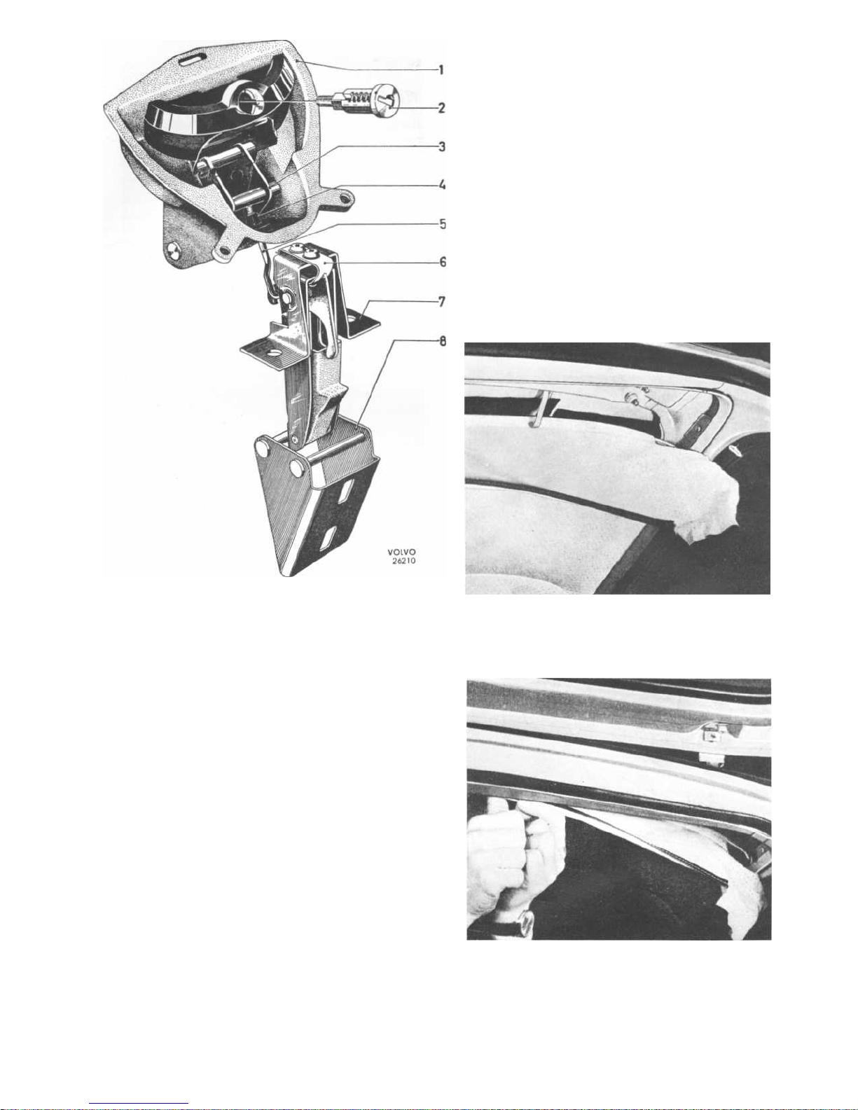
isattached to the luggage compartment lid by means of screws. The catch fitting is
attached to the body with two screws. The lock is
adjusted by screwing the link
(5,
Fig. 41) up or
down. The lock cylinder (2) is attached to the
handle with a nut. The catch fitting is provided
with oval holes in order to permit adjustment.
8-
1
6
Fig.
38.
Releasing the torsion rod
Fig.
39.
Removing the torsion rod
VOLVO
1
01 060
VOLVO
1
01 061
23235
Fig. 40.
Removing circlip for lock press-button
Page 18
TAILGATE, STATION WAGON
Upper tailgate
REMOVING THE UPPER TAILGATE
1.
Unscrew the upper support from the tailgate.
2.
Late production. Unscrew the gas spring from
the tailgate.
3.
Carefully pull down the headlining at the rear
edge beginning in the middle and continuing
outwards towards the corners. The teazel strip
at the corners is bent out slightly with a putty
knife. The fabric is then carefully lifted off the
projection of the teazel strip with the help
of the putty knife. Remove the headlining
fabric up to the rear stretcher as shown in
Fig. 42.
P 120
4.
Unscrew the nuts for the hinges and remove
the latter.
FITTING THE UPPER TAILGATE
1.
Place the hinges with packings in position.
Screw on the nuts, adjust the position of the
tailgate and tighten the nuts.
2.
Fold the plastic strip for the headlining as
shown in Fig. 43 and press it up into position
with the help of the putty knife. Attach the
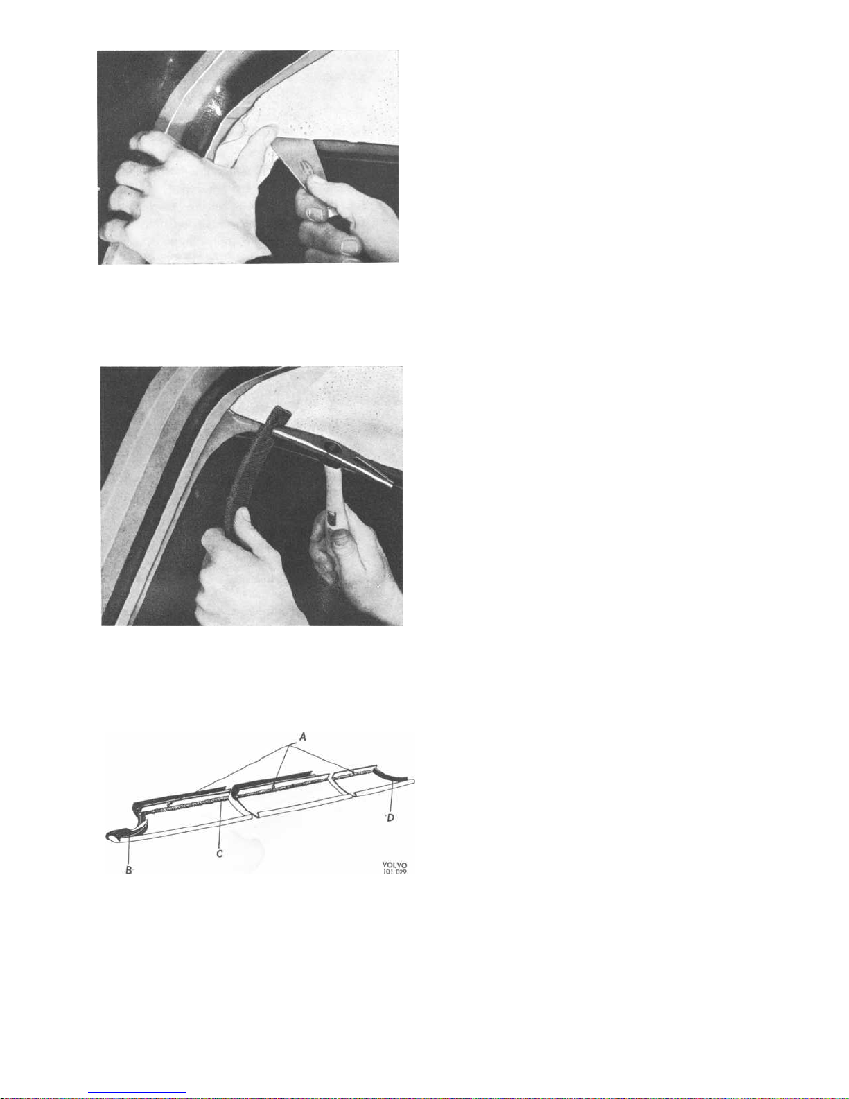
fabric at the corners as shown in Fig. 44.
3.
Adjust the teazel strip against the body with
a hammer and piece of rubber as shown in
Fig. 45.
VOLVO
1
00 954
Fig. 42.
Headlining fabric removed to expose
upper tailgate hinge nuts
Fig. 43. Folding and fitting rear plastic strip
VOLVO
1
00 951
817
Fig. 41.
Lock for luggage compartment
li
d,
l
ate production
1.
Handle
5.
Link
2.
Lock cylinder
6.
Guide spring
3.
Lock mechanism
7.
Lock
4.
Rubber bush
8.
Catch fitting
Page 19
P 120
VOLVO
100 953
Fig.
44.
Fitting headlining fabric in corner
8-
1
8
Fig. 45.
Adjusting teazel strip
Fig. 46.
Window moulding
A. Indentations
B.
Rubber strip
C.
Sealing compound
D.
Rubber strip
VOLVO
1
00 952
TRIM MOULDINGS
Waist mouldings
The waist mouldings, and the upper trim moulding
for the door on the
P 120
2-door model, are
attached
with clips. The mouldings are removed
with the help of a putty knife with which they are
carefully unfastened. Before fitting the mouldings,
the holes should be filled with sealing compound.
Window mouldings
REMOVING
Wind down the window. Apply masking tape or
similar as shown in Fig.
47
i
n order to protect the
paintwork. From inside, place a screwdriver under
the rear edge of the moulding in line with the indentations which secure it, see Figs. 46 and 48. Prise
carefully upwards with the screwdriver and at the
same time pull outwards and downwards with the
hand so that the rear retaining spring can be hooked
off
with SVO
2297,
see Fig.
49.
Carefully pull out
the moulding backwards.
FITTING
Stick the profile rubber strips at both ends of the
window moulding and apply sealing compound
along the inner section of the moulding, see Fig.46.
Place the retaining springs in position and apply
sealing compound as shown in Fig. 50. Push the
window moulding in position under the rubber strip
of the ventilation window as shown in Fig. 51. Lift
the inner ridge of the moulding over the metal
edge of the door and press down so that the indentations, Fig. 46, locate in the holes in the sheet
metal edge. Press up the retaining springs with
SVO 2297,
see Fig. 52.
Moulding for rear side window,
Station Wagon
When fitting the clips for the moulding, one of the
l
egs is inserted in the recess in the moulding, the
clip pressed together and the other leg inserted.
Apply sealing compound over the fastenings and
press the moulding into position.
Page 20
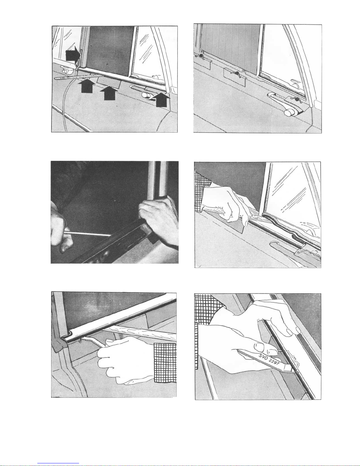
Fig. 47.
Application of masking tape
Fig, 48.
Removing window moulding
Fig. 49.
Removing spring
P 120
Fig. 50. Position of springs
Fig. 51.
Fitting window moulding
Fig. 52. Fitting spring
8--19
Page 21
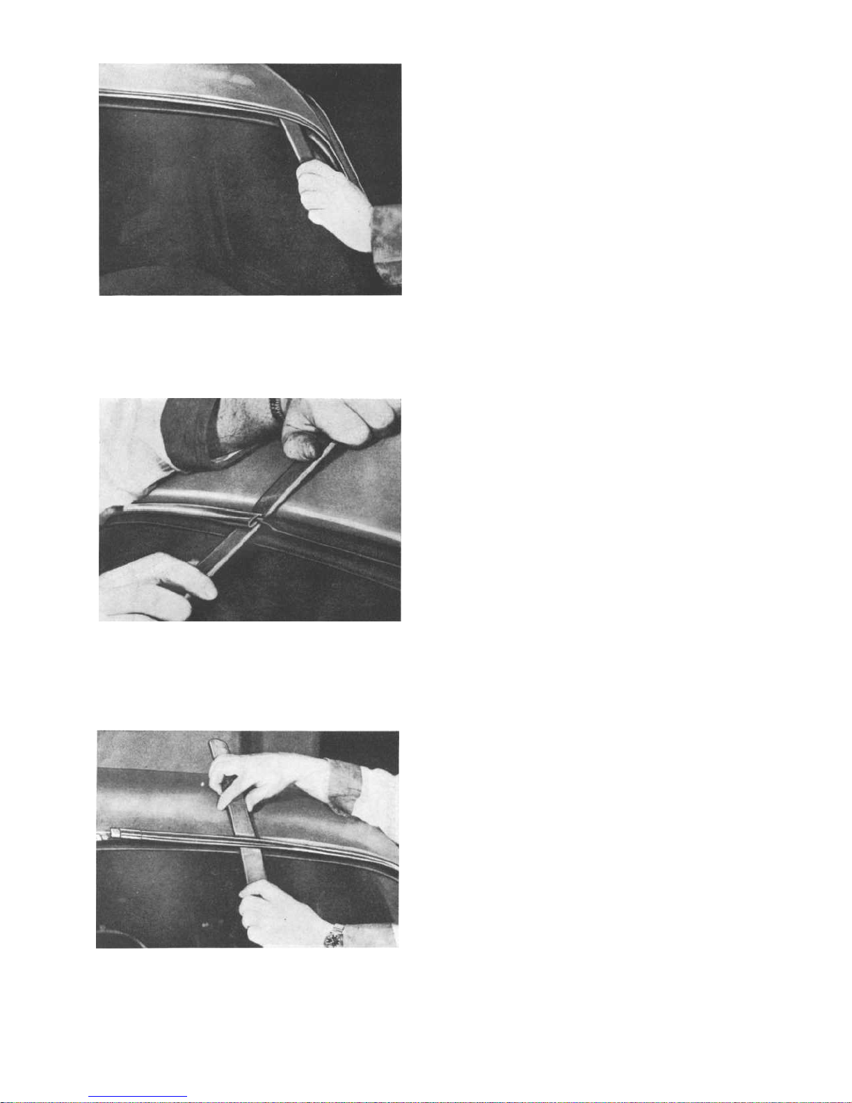
P 120
Fig. 53.
Removing trim moulding
8--
2
0
Fig. 55.
Removing trim moulding
VOLVO
199 969
VOLVO
1
00 968
Fig. 54.
Removing trim moulding from rubber strip
VOLVO
1
00 966
Trim mouldings, windscreen
REMOVING
1.
Remove the trim moulding from the rubber
strip
by inserting a moistened nylon putty
knife
between the strips and moving it all,
round, see Fig. 53. (Do not pull off the trim
moulding).
2.
Push over the joining pieces to one of the
halves of the moulding.
3.
Remove the trim moulding by prising out the
ridge
of the rubber strip from the trim mouldi
ng with a moistened wooden putty knife and
releasing the trim moulding in the middle with
another putty knife as shown in Fig. 54. Prise
off the moulding carefully while releasing the
rubber strip with the other putty knife, see Fig.
55.
FITTING
Moisten a 4.0 mm (5/32") leather cord in soap solution or paraffin and place it in the groove of the
rubber strip for the trim moulding. Place one half
of the trim moulding in position and hold it there
while pulling the leather cord out upwards over
the
moulding so that it is pressed against the
rubber strip as shown in Fig.
56.
Push on the
j
oining pieces and repeat the procedure with the
other half of the moulding. Adjust the position of
the joining pieces over the joints.
Trim mouldings, rear window
[
2- and 4-door models]
REMOVING
1.
Push the joining pieces at the lower corners
backwards. Release the lower trim moulding
by pressing it upwards out of the rubber strip
with a wooden putty knife. Pull the trim
moulding upwards carefully and follow round
with the putty knife.
2.
Release the side mouldings in the same way
with the putty knife and remove them. Remove
the angular joining pieces by pulling them
downwards and turning inwards at the same
ti
me.
3.
Remove the upper trim moulding in the same
way as the lower one.
FITTING
1.
Moisten a 4.0 mm (5/32") feather cord in soap
solution or paraffin
and place it in the groove
of the rubber strip for the trim moulding. Start
and finish at one of the upper corners.
Page 22
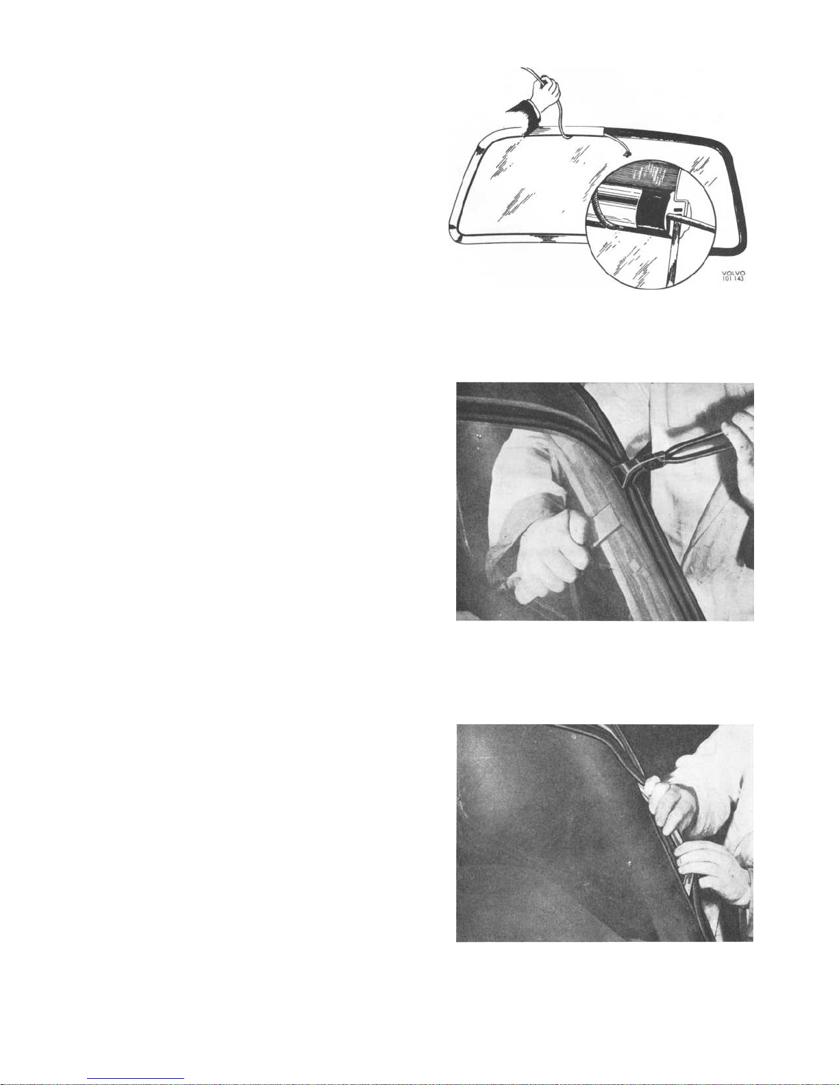
i
ngs".
3.
Release the rubber strip both from the wind-
screen and sheet metal by inserting a wooden
putty knife moistened in synthetic washing
solution (the putty knife should be moistened
now and then during the course of the work)
between the rubber strip and windscreen and
between the rubber strip and sheet metal
respectively.
4.
Start removing the rubber strip in the upper
l
eft-hand corner by prising the rubber strip
over the sheet metal edge from inside and
at the same time carefully pulling out the strip
from outside with a pair of grips as shown in
Fig. 57. Then carefully pull off the strip by
hand all round as shown in Fig. 58 and remove
the windscreen.
Remove all sealing compound from the sheet
metal. If it has dried on, first carefully scrape
off the sealing compound and then wash clean
with naphtha. Check that the sheet metal edge
is
not deformed. If the sealing compound has
not dried on, clean the rubber strip with naphtha, otherwise replace it.
FITTING THE WINDSCREEN
1.
Place the windscreen on a stand as shown
i
n Fig. 59. Moisten the outer edge of the
windscreen and fit the rubber strip starting
at one of the corners. Adjust the strip so that
it lies correctly all round.
Fig. 57.
Releasing rubber strip
Fig. 58.
Removing rubber strip
P 120
VOLVO
1
00 967
VOLVO
1
00 910
8-21
Fig. 56. Fitting trim moulding
2.
Place the upper trim moulding in position and
press it up against the rubber strip. Pull out
the leather cord and press in the trim mouldi
ng at the same time. Fit the angular joining
pieces.
3.
Press on the side mouldings and push them
up into the joining pieces. Fit the side mould-
i
ngs in the same way as the upper trim
moulding.
4.
Fit the lower trim moulding in the same way
as the upper one. Fit the lower joining pieces.
WINDOWS
Windscreen
REMOVING THE WINDSCREEN
1.
Remove the interior rear view mirror, interior
trim
mouldings round the windscreen and the
windscreen wiper arms. Place protective padding over the bonnet, front seats and backrests.
2.
Remove the trim mouldings as described in
operations 1-3, "Removing the trim mould-
Page 23
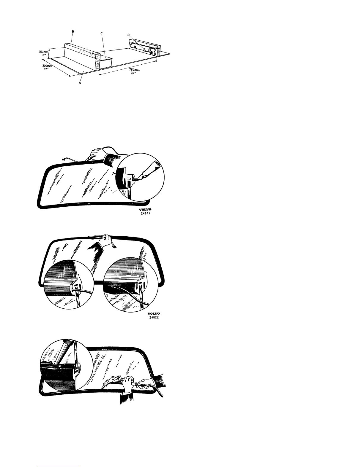
P 120
8-
2 2
Fig. 60. Placing cord in rubber strip
Fig. 61.
Fitting windscreen
VOLVO
24813
Fig. 62.
Applying sealing compound
VOLVO
1
01 141
Fig. 59.
Stand for windscreen when fitting
rubber strip
A.
Sheet of plywood,15
mm(19/32")
B.
Foam plastic, 1-1.5"
C.
Storage compartment
D.
Hooks for sealing compound gun
2.
Fit a cord (preferably terylene) of a suitable
size in the groove of the rubber strip for the
sheet metal edge, beginning at the top centre
as shown in Fig, 60.
3.
Place the windscreen in position with rubber
strip fitted.
Wearing working gloves, carefully
strike the windscreen a few blows with the
palm of the hand so that it makes good contact all round. Then carefully pull out the cord
from inside.
4.
This
will
cause the rubber strip to "creep"
over the sheet metal edge as shown in Fig. 61.
It
may sometimes be necessary to adjust the
position of the windscreen with the palm of
the hand. If the cord is difficult to pull out, this
may cause damage to the strip, in which case
strike the windscreen from inside with the
palm of the hand and vice versa if the rubber
strip does not "creep" over the edge of the
sheet metal properly.
5.
Check that the rubber strip seals well all
round. If necessary adjust the position of the
windscreen both vertically and laterally by
striking with the palm of the hand.
6.
Fit the trim mouldings as previously described.
7.
Seal the joints between the rubber strip and
windscreen and rubber strip and sheet metal
with sealing compound using a gun with a flat
nylon nozzle as shown in Fig, 62. Make sure
that the sealing compound fills the joint well.
Scrape off surplus sealing compound and
wash the windscreen and sheet metal with
naphtha and then polish clean.
8.
Fit the interior trim mouldings, rear view mirror
and windscreen wiper arms.
Rear window
REMOVING AND FITTING
See the corresponding sections under the heading
"Windscreen".
Rear ventilation window, 2-door model
REMOVING
Unscrew the two safety belt attaching bolts, remove
the entry handle and lift off the cover plate, after
which the ventilation window hinge screws are
accessible, see Fig. 63.
Page 24
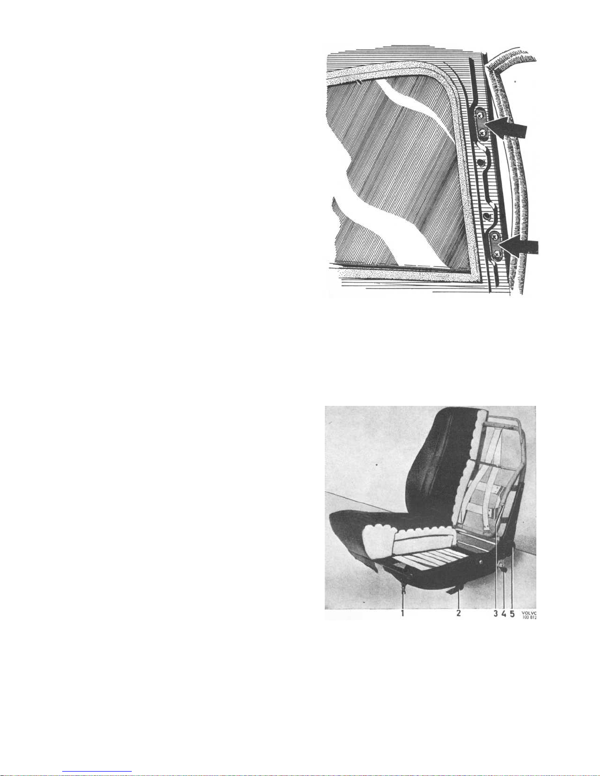
SEATS
Front seats
REMOVING, EARLY PRODUCTION
Lift
out the seat cushion. Press down the catch for
adjusting the longitudinal position of the seat and
push the seat forwards until the slide rails release
from the frame. It may be necessary to lift the pull
wire for the catch halfway between the slide rails.
An intermediate production type has a plastic wed-
ge which limits the movement of the catch. This
wedge must be taken out before the seat can be
removed.
REMOVING, LATE PRODUCTION
Unfasten the press-button which holds the seat
cushion to the frame and remove the seat cushion.
Unscrew the four attaching screws for the slide rails.
Lift off the seat.
ADJUSTING THE FRONT SEAT, LATE PRODUCTION
1.
The inclination of the seat is adjusted with the
eyebolt (1, Fig. 64) at the front edge of the
seat. Slacken the adjusting screw and adjust
the eyebolt to the desired position.
2.
The height of the seat is adjusted by attaching
the rail in a suitable hole in the bracket (2).
3.
The lumbar support is adjusted with the screw
(3).
On a number of earlier vehicles with lum-
bar support where the adjusting device does
not have a countersink, the adjusting screw
can most easily be found by pressing the upholstery at the adjusting screw hole slightly
downwards and backwards.
Rear seat, Station Wagon
REMOVING THE BACKREST
Release the catch and tip the backrest slightly for-
wards.
Move aside the nylon washer at the lower
l
eft-hand corner of the backrest and insert a narrow
screwdriver as shown in Fig. 65. Press in the conical
catch pin and lift out the backrest.
Fig, 63.
Attachment of rear ventilation window
Fig. 64.
Front seat
1.
Adjustmentofseat inclination
2.
Adjustmentofseat height
3.
Adjustment of lumbar support
4.
Longitudinal adjustmentofseat
5.
Adjustment of backrest inclination
P 120
8-23
Page 25
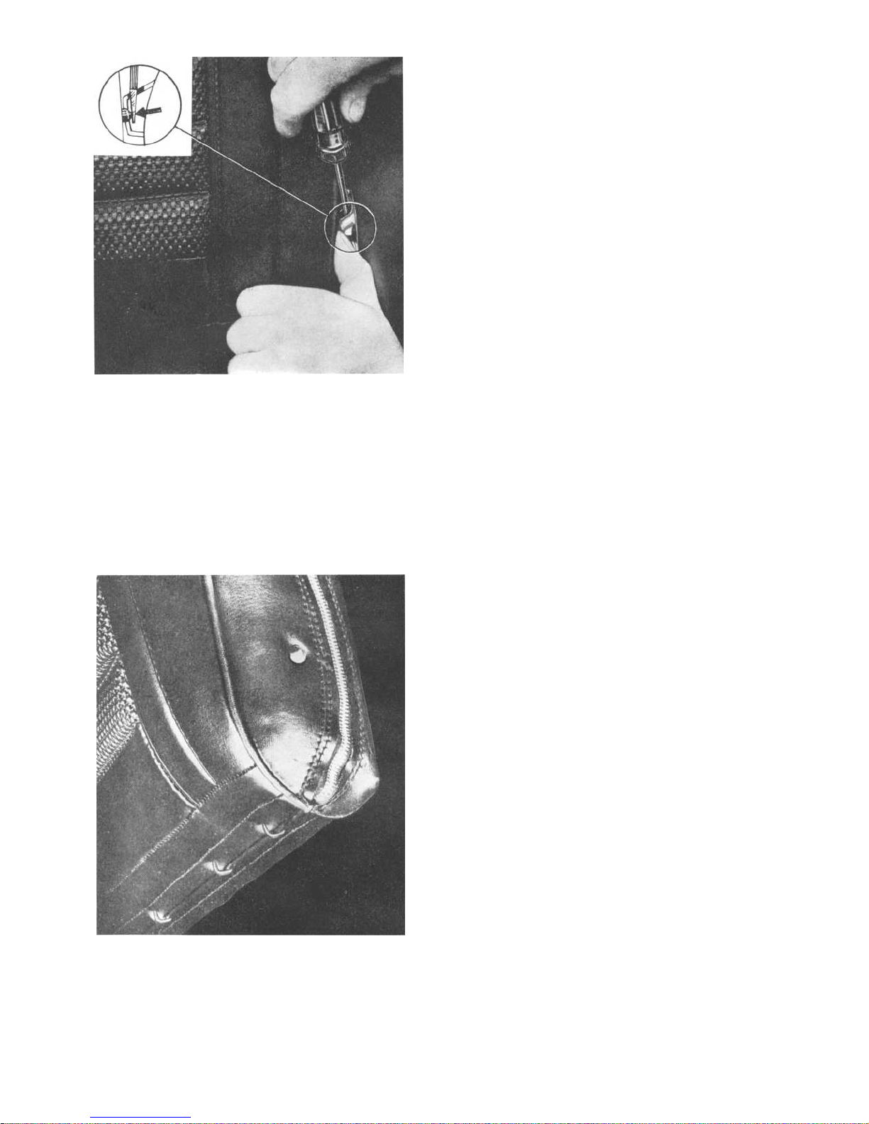
P 120
Fig. 65.
Releasing catch for removing rear seat
backrest on Station Wagon
824
Fig. 66.
Underside of rear seat backrest,
Station
Wagon
VOLVO
1
01 0:8
VOLVO
1
00 955
To remove the upholstery, undo the lacing at the
l
ower edge, open the zip-fastener, after which the
upholstery can be removed, see Fig. 66.
When fitting the backrest, place the nylon washer
on the pin and fit the right-hand pin in position.
Move the left-hand, conical pin towards the upper
side of the fitting, move the nylon washer over the
fitting
and press down the seat. If necessary, the
catch can be moved aside with a screwdriver.
REMOVING LOCK MECHANISM FOR BACKREST
The lock mechanism is accessible after the lacing
at the lower edge of the backrest has been undone,
the zip-fastener opened, see Fig. 66, and the upholstery removed.
UPHOLSTERY
Repairing inner roof (headlining)
STRETCHING THE HEADLINING FOR REMOVING
SMALL HOLES AT THE OUTER EDGE
Inmost cases where there are small holes at the
outer edge of the headlining it is sufficient just to
stretch it.
1.
Remove the interior light, sun visors, rear view
mirror and upper part of the windscreen trim
moulding.
Remove the side mouldings as
shown in Fig. 67.
2.
Release the trim strip. Prise out the teazel strip
with the help of a putty knife.
3.
Pull out the trim strip as shown in Fig. 68 and
remove the headlining from the teazel strip
with the help of a putty knife.
4.
Stretch the headlining so that the damaged
part can be tucked in behind the teazel strip
as shown in Fig. 69. The headlining should be
stretched
well,
but not too hard so that it
wrinkles.
5.
Place the trim strip•i
n position and knock the
teazel strip against the side of the body with
the help of a hammer and piece of rubber as
shown in Fig. 70.
6.
Fit the interior light, sun visors, rear view
mirror and trim mouldings for the windscreen,
see Fig. 71.
Page 26
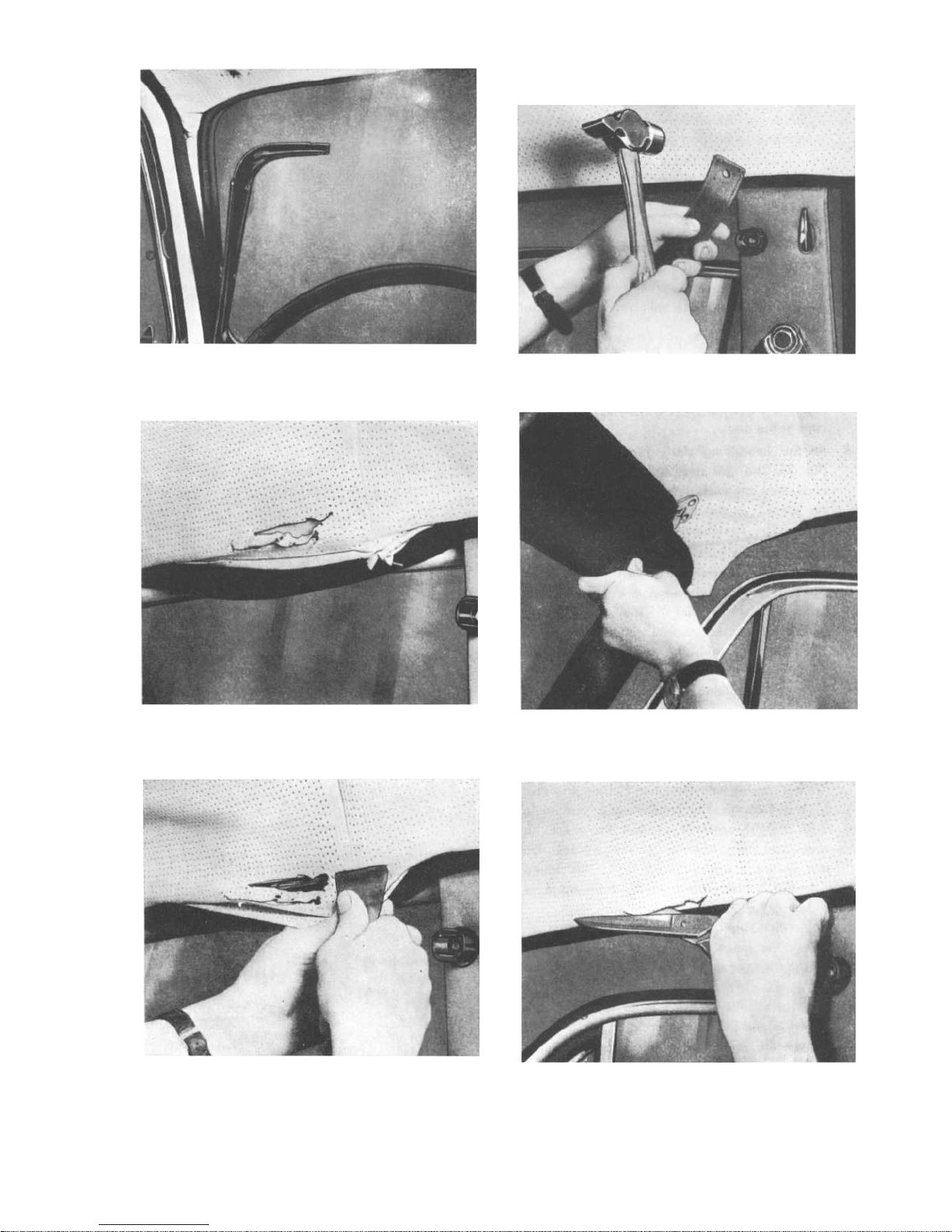
Fig. 67. Inner trim mouldings removed
Fig. 68.
Headlining and trim strip released
Fig. 69.
Stretching the headlining
Fig. 70.
Knocking in the teazel strip
Fig. 71.
Fitting sun visor
Fig. 72.
Cutting away the headlining
P 120
8-25
Page 27
P 120
REPLACING THE HEADLINING, 2- AND 4-DOOR
VEHICLES
1.
Remove the interior light, sun visors, rear view
mirror and upper part of the trim moulding for
the
windscreen. Release the side mouldings
as shown in Fig. 67.
2.
Cut away the old headlining as shown in Fig.
72.
3.
Remove the trim strip and remainder of the old
headlining.
4.
Adjust the teazel strip so that it fits well against
the trim strip and check the screws of the teazel
strip.
5.
Fit the stretchers in the new headlining. N.B.
The stretchers are numbered 1-5 with 1 at
the front next to the windscreen. Make sure
that the stretchers are provided with rubber
caps at the ends.
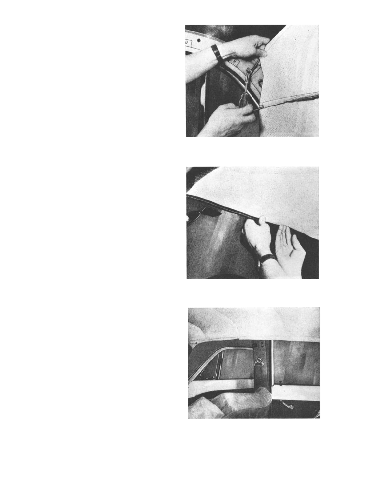
6.
Fit the headlining starting at the back, see
Fig. 73. The rear stretchers are attached with
clips,
one on each side. The other stretchers
are placed on the sheet metal edge over the
doors. The stretchers should stand vertically.
7.
Fold over the plastic strip and fit above the
windscreen as shown in Fig. 74.
8.
Fit the headlining above the rear window
as described in point 7. The seam running
across at the back should come at an equal
distance from both the corners of the rear
window, see Fig. 75.
9.
Stick the headlining to the body metal at the
rear window and to the wheel arch plate.
10.Fit the sun visors, see Fig. 71.
11.
Stretch up the headlining in the teazel strip.
This is done stretcher by stretcher beginning
on both sides with stretcher 1, then stretcher
2, 3 and so on. The headlining is pushed in
and straight upwards so that there are no
creases at the windscreen or rear window. Do
not secure the headlining along the whole
side but leave a piece at the front edge as
shown in Fig. 71.
12.Fit the trim strip.
1
3.
Knock the teazel strip against the body side
with a hammer and piece of rubber as shown
i
n Fig. 70.
14.
Cut out a hole for the interior light. Pull out
the wires and fit the interior light.
15.
Secure the remaining part of the headlining
at the corners of the windscreen.
16.
Fit the windscreen trim moulding.
8-26
Fig. 73.
Fitting rear clip
Fig. 74.
Folding over and fitting the plastic strip
Fig. 75.
Headlining ready for stretching
Page 28
P 120
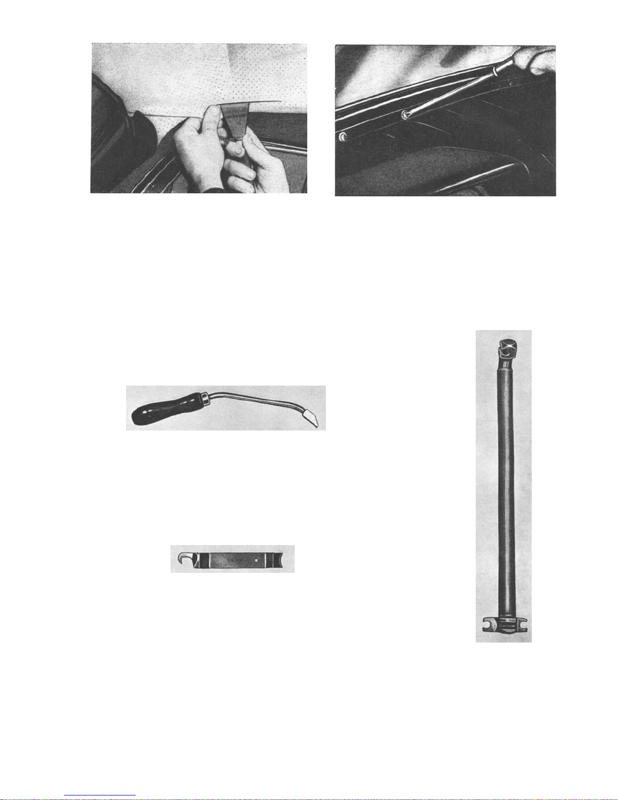
Fig. 77.
Removing trim moulding for windscreen
Fig. 76.
Stretching the headlining and attaching
to teazel strip
Instrument panel
REMOVING THE INSTRUMENT PANEL
The instrument panel is secured to the body with screws. These are accessible after the front doors have
been opened and the inner trim moulding for the windscreen removed as shown in Fig. 77.
SPECIAL TOOLS FOR CARRYING OUT WORK ON THE BODY
SVO 2572
SVO 2297
SVO 2486
SVO 2297 Tool for removing clips on door and
window winder handles, and for
removing and fitting spring clips
for window mouldings.
SVO 2486 Tool for fitting plate nut.
SVO 2572 Tool for removing and fitting torsion
stay for luggage compartment lid.
8-21
Page 29
Page 30
 Loading...