

Page 1

OPERATOR’S MANUAL
5.0L, 5.7L, 8.1L
SX-A, DPS-A, XDP-B
Page 2

DAN
Denne instruktionsbog kan bestilles på dansk.
Bestillingskupon findes i slutningen af instruktionsbogen.
DEU
EÎÎ
FRA
ITA
NED
POR
RUS
SUO
Diese Betriebsanleitung ist auch auf Deutsch erhältlich.
Ein Bestellcoupon ist am Ende der Betriebsanleitung zu finden.
Este libro de instrucciones puede solicitarse en español.
El cupón de pedido se encuentra al final del libro.
¡ıÙ¸ ÙÔ Â„˜ÂÈÒfl‰ÈÔ ˜ÒfiÛÁÚ ‰È·ÙflËÂÙ·È ÛÙÁÌ ·„„ÎÈÍfi „βÛÛ·. √È· Ì· ð·Ò·„„ÂflÎÂÙ ›Ì·
·ÌÙflÙıðÔ, ÛıПрОБТ˛ÛÙ ÙÁ ˆ¸ÒÏ· ðÔı ‚ÒflÛÍÂÙ·È ÛÙÔ Ù›ÎÔÚ ·ıÙÔ˝ ÙÔı „˜ÂÈÒȉflÔı ˜ÒfiÛÁÚ.
Ce manuel d’instructions peut être commandé en français.
Vous trouverez un bon de commande à la fin du manuel d’instructions.
Questo manuale d’istruzioni può essere ordinato in lingua italiana.
Il tagliando per l’ordinazione è riportato alla fine del manuale.
Dit instructieboek kan worden besteld in het Nederlands.
De bestelcoupon vindt u achter in het instructieboek.
Este manual de instruções pode ser encomendado em português.
O talão de requerimento encontra-se no fim do manual.
Данное руководство оператора имеется на турецком и русском языках.
Для получения инструкции на нужном языке заполните форму в конце инструкции.
Tämän ohjekirjan voi tilata myös suomenkielisenä.
Tilauskuponki on ohjekirjan lopussa.
SVE
TÜR
Den här instruktionsboken kan beställas på svenska.
Beställningskupong finns i slutet av instruktionsboken.
Bu kullanıcı el kitabı Türkçe dillerinde mevcuttur.
Bir nüshasını sipariş etmek için kullanıcı el kitabının sonundaki formu doldurun.
CALIFORNIA PROPOSITION 65 WARNING
Engine exhaust, some of its constituents, and a broad range of engine parts are known to the
State of California to cause cancer, birth defects, and other reproductive harm. Additionally, lubricants, fuels, and other fluids used in engines–including any waste created through the wearing of engine parts–contain or produce chemicals known to the State of California to cause
cancer and birth defects or other reproductive harm.
Battery posts, terminals, and related accessories contain lead and lead compounds. Wash your
hands after handling. Used engine oil contains chemicals that have caused cancer in laboratory
animals. Always protect your skin by washing thoroughly with soap and water.
Copyright © 2007 Volvo Penta of the Americas, Inc. All rights reserved. This publication may not be copied, photocopied, reproduced, or converted to any electronic or machine-readable form in whole or in part without the express written consent from
Volvo Penta of the Americas, Inc.
Page 3

This manual applies to the following engines and sterndrives.
Raw Water Cooled
Model Spec. No. Drive
5.0L
5.7L
8.1L
5.0L
5.0GXiE-J 3869446
5.0OSiE-J 3869451 XDP-B
5.7GiE300-J
5.7GXiE-J
5.7OSiE300-J
5.7OSXiE-J
8.1GiE-J
8.1GXiE-J
8.1OSiE-J 3869454 XDP-B
3869447
3869448
3869452
3869453
3869449
3869450
SX-A
DPS-A
SX-A
DPS-A
XDP-B
DPS-A
Closed Cooling System
Model Spec. No. Drive
5.0GXiE-JF 3869431
5.0OSiE-JF 3869432 XDP-B
SX-A
DPS-A
5.7L
8.1L
5.7GiE300-JF
5.7GXiE-JF
5.7OSiE300-JF
5.7OSXiE-JF
8.1GiE-JF
8.1GXiE-JF
8.1OSiE-JF 3869438 XDP-B
3869433
3869435
3869434
3869436
3869437
3869439
SX-A
DPS-A
XDP-B
DPS-A
Page 4

Notes
. . . . . . . . . . . . . . . . . . . . . . . . . . . . . . . . . . . . . . . . . . . . . . . . . . . . . . . . . . . . . . . . . . . . . . . . . . . . . . . . . . . . . . . . .
. . . . . . . . . . . . . . . . . . . . . . . . . . . . . . . . . . . . . . . . . . . . . . . . . . . . . . . . . . . . . . . . . . . . . . . . . . . . . . . . . . . . . . . . .
. . . . . . . . . . . . . . . . . . . . . . . . . . . . . . . . . . . . . . . . . . . . . . . . . . . . . . . . . . . . . . . . . . . . . . . . . . . . . . . . . . . . . . . . .
. . . . . . . . . . . . . . . . . . . . . . . . . . . . . . . . . . . . . . . . . . . . . . . . . . . . . . . . . . . . . . . . . . . . . . . . . . . . . . . . . . . . . . . . .
. . . . . . . . . . . . . . . . . . . . . . . . . . . . . . . . . . . . . . . . . . . . . . . . . . . . . . . . . . . . . . . . . . . . . . . . . . . . . . . . . . . . . . . . .
. . . . . . . . . . . . . . . . . . . . . . . . . . . . . . . . . . . . . . . . . . . . . . . . . . . . . . . . . . . . . . . . . . . . . . . . . . . . . . . . . . . . . . . . .
. . . . . . . . . . . . . . . . . . . . . . . . . . . . . . . . . . . . . . . . . . . . . . . . . . . . . . . . . . . . . . . . . . . . . . . . . . . . . . . . . . . . . . . . .
. . . . . . . . . . . . . . . . . . . . . . . . . . . . . . . . . . . . . . . . . . . . . . . . . . . . . . . . . . . . . . . . . . . . . . . . . . . . . . . . . . . . . . . . .
. . . . . . . . . . . . . . . . . . . . . . . . . . . . . . . . . . . . . . . . . . . . . . . . . . . . . . . . . . . . . . . . . . . . . . . . . . . . . . . . . . . . . . . . .
. . . . . . . . . . . . . . . . . . . . . . . . . . . . . . . . . . . . . . . . . . . . . . . . . . . . . . . . . . . . . . . . . . . . . . . . . . . . . . . . . . . . . . . . .
. . . . . . . . . . . . . . . . . . . . . . . . . . . . . . . . . . . . . . . . . . . . . . . . . . . . . . . . . . . . . . . . . . . . . . . . . . . . . . . . . . . . . . . . .
. . . . . . . . . . . . . . . . . . . . . . . . . . . . . . . . . . . . . . . . . . . . . . . . . . . . . . . . . . . . . . . . . . . . . . . . . . . . . . . . . . . . . . . . .
. . . . . . . . . . . . . . . . . . . . . . . . . . . . . . . . . . . . . . . . . . . . . . . . . . . . . . . . . . . . . . . . . . . . . . . . . . . . . . . . . . . . . . . . .
. . . . . . . . . . . . . . . . . . . . . . . . . . . . . . . . . . . . . . . . . . . . . . . . . . . . . . . . . . . . . . . . . . . . . . . . . . . . . . . . . . . . . . . . .
. . . . . . . . . . . . . . . . . . . . . . . . . . . . . . . . . . . . . . . . . . . . . . . . . . . . . . . . . . . . . . . . . . . . . . . . . . . . . . . . . . . . . . . . .
. . . . . . . . . . . . . . . . . . . . . . . . . . . . . . . . . . . . . . . . . . . . . . . . . . . . . . . . . . . . . . . . . . . . . . . . . . . . . . . . . . . . . . . . .
. . . . . . . . . . . . . . . . . . . . . . . . . . . . . . . . . . . . . . . . . . . . . . . . . . . . . . . . . . . . . . . . . . . . . . . . . . . . . . . . . . . . . . . . .
. . . . . . . . . . . . . . . . . . . . . . . . . . . . . . . . . . . . . . . . . . . . . . . . . . . . . . . . . . . . . . . . . . . . . . . . . . . . . . . . . . . . . . . . .
. . . . . . . . . . . . . . . . . . . . . . . . . . . . . . . . . . . . . . . . . . . . . . . . . . . . . . . . . . . . . . . . . . . . . . . . . . . . . . . . . . . . . . . . .
. . . . . . . . . . . . . . . . . . . . . . . . . . . . . . . . . . . . . . . . . . . . . . . . . . . . . . . . . . . . . . . . . . . . . . . . . . . . . . . . . . . . . . . . .
. . . . . . . . . . . . . . . . . . . . . . . . . . . . . . . . . . . . . . . . . . . . . . . . . . . . . . . . . . . . . . . . . . . . . . . . . . . . . . . . . . . . . . . . .
. . . . . . . . . . . . . . . . . . . . . . . . . . . . . . . . . . . . . . . . . . . . . . . . . . . . . . . . . . . . . . . . . . . . . . . . . . . . . . . . . . . . . . . . .
. . . . . . . . . . . . . . . . . . . . . . . . . . . . . . . . . . . . . . . . . . . . . . . . . . . . . . . . . . . . . . . . . . . . . . . . . . . . . . . . . . . . . . . . .
. . . . . . . . . . . . . . . . . . . . . . . . . . . . . . . . . . . . . . . . . . . . . . . . . . . . . . . . . . . . . . . . . . . . . . . . . . . . . . . . . . . . . . . . .
. . . . . . . . . . . . . . . . . . . . . . . . . . . . . . . . . . . . . . . . . . . . . . . . . . . . . . . . . . . . . . . . . . . . . . . . . . . . . . . . . . . . . . . . .
. . . . . . . . . . . . . . . . . . . . . . . . . . . . . . . . . . . . . . . . . . . . . . . . . . . . . . . . . . . . . . . . . . . . . . . . . . . . . . . . . . . . . . . . .
. . . . . . . . . . . . . . . . . . . . . . . . . . . . . . . . . . . . . . . . . . . . . . . . . . . . . . . . . . . . . . . . . . . . . . . . . . . . . . . . . . . . . . . . .
. . . . . . . . . . . . . . . . . . . . . . . . . . . . . . . . . . . . . . . . . . . . . . . . . . . . . . . . . . . . . . . . . . . . . . . . . . . . . . . . . . . . . . . . .
Page 5
21169
Welcome Aboard
Congratulations on choosing a new boat equipped with a
Volvo Penta marine engine. Volvo Penta has been building
marine engines since 1907. Quality, operating reliability,
and innovation have made Volvo Penta a world leader in the
marine engine industry. From engineering design and
manufacturing to support activities in Parts, Service, and
Sales, high standards have been set to ensure your pride
and satisfaction as the owner of a Volvo Penta product.
As owner of a Volvo Penta marine engine, we would also
like to welcome you to a worldwide network of dealers and
service workshops to assist you with technical advice,
service requirements and replacement parts. Please
contact your nearest authorized Volvo Penta dealer for
assistance.
We wish you many pleasant voyages.
Our Core Values: Quality, Safety,
Environmental Care
The values and qualities that Volvo Penta expresses are
what make the company unique. From the very beginning,
safety and quality have stood at the heart of the
development of all of our products, processes, and services.
It is on these values and qualities that the Volvo Penta
corporate identity, brand position and legal status have
been founded. Today’s core values of quality, safety, and
care for the environment remain central to Volvo Penta.
They express what we believe in as a company and will
ultimately help us to survive.
Quality is a value that traditionally referred to product
quality but now encompasses all aspects of our products
and services. In today’s competitive environment, Volvo
Penta’s quality commitment extends beyond industrial
craftsmanship and engineering ingenuity to embrace care
for the customer throughout the life of the product.
Safety will always be our most distinguishing core value.
Historically embedded in the quality of all Volvo products, it
also encompasses personal, family, business, and
environmental values.
Environmental Care in all operations, from design to
production, distribution, service, and recycling, is an integral
part of the Volvo quality commitment towards customers,
employees, and the community. By embracing the
environment as a core value, Volvo demonstrates its
understanding of the environmental impact its products
have upon nature and the shared urban and rural
surroundings.
Volvo Penta continually commits a considerable part of its
development resources toward minimizing the
environmental impact of its products. Examples of areas
where we are always looking for improvements are exhaust
emissions, noise levels, and fuel consumption.
Regardless of whether your Volvo Penta engine is installed
in a boat used for pleasure or commercial operation,
incorrect operation or improper maintenance of the engine
will result in disturbance or damage to the environment.
In this owner’s manual there are a number of service
procedures, which, if not followed, will lead to an increase in
the engine’s impact on the environment, and on running
costs and a reduction in service life. Always observe
recommended service intervals and make a habit of
checking that the engine is operating normally every time
you use it. Contact an authorized Volvo Penta dealer if you
cannot correct the fault yourself.
Remember that most chemicals used on boats are harmful
to the environment if used incorrectly. Volvo Penta
recommends the use of biodegradable degreasing agents
for all cleaning. Always dispose of engine and transmission
oil waste, old paint, degreasing agents and cleaning residue
etc. at proper disposal areas so that they do not harm the
environment.
Adapt speed and distance during your boat trips so that
swell and noise generated by the boat do not disturb or harm
wildlife, moored boats, docks, etc. Wherever you land or
cruise, please show consideration and always leave the
areas you visit as you would like to find them yourself.
Page 6

CONTACT INFORMATION
Consumer Affairs Department
Volvo Penta of the Americas, Inc.
1300 Volvo Penta Drive
Chesapeake, Virginia 23320, USA
Phone: (757) 436-5100 • Fax: (757) 436-5153
http://www.volvopenta.com
Volvo Action Service - North America
P.O. Box 26113
Greensboro, North Carolina 27402-6113
Toll Free: (877) 33-PENTA • Phone: (336) 393-4966
http://myactionservice.com/English/VAS_Penta.asp
World-wide Dealer Locator
http://www.volvopenta.com
Page 7

Table of Contents
Table of Contents
Safety Information 5
General Information ..................................................5
Safety Precautions (Maintenance and Service)........6
Knowledge ................................................................... 6
Engine Decals.............................................................. 6
Stop the Engine............................................................ 6
Lifting the Engine ......................................................... 6
Before Starting the Engine........................................... 6
Washing the Engine..................................................... 6
Fire and Explosion ....................................................... 7
Fuel and Lubrication Oil ......................................... 7
Non-Original Components...................................... 7
Batteries ................................................................. 7
Start Spray ............................................................. 7
Hot Surfaces and Fluids............................................... 8
Cooling System............................................................ 8
Fuel System ................................................................. 8
Lubrication System....................................................... 8
Electrical System.......................................................... 8
Carbon Monoxide Poisoning ........................................ 8
Chemicals .................................................................... 8
Safety Precautions While Operating the Boat...........9
Your New Boat............................................................. 9
Accidents...................................................................... 9
Maneuvering ................................................................ 9
Emergency Stop Switch............................................... 9
Daily Checklist.............................................................. 9
Refueling...................................................................... 9
Do not Start the Engine................................................ 9
“Station Wagon” Effect & Carbon Monoxide ...........10
Safety Checklists.....................................................11
Planning Your Trip ..................................................... 11
Trip Checklist........................................................ 11
Safety Equipment....................................................... 11
Safety Equipment Checklist ................................. 11
Replacement Parts and Tools Checklist .................... 11
Basic Safety Rules of Boating.................................12
High Performance Boat Operation............................. 12
Introduction 13
Care of the Environment .........................................13
Fuel and Oils ...........................................................13
Breaking-in..............................................................13
Certified Engines.....................................................14
Power Ratings.........................................................15
Load Condition (Speed of Planing Hull) ..................... 15
General Information 17
Warranty Information...............................................17
Warranty Registration Form....................................... 17
Doing Your Own Maintenance and Repairs............... 17
Volvo Action Service (VAS)........................................ 17
Volvo Penta Dealer Network...................................... 17
Toll-free Dealer Locator Service........................... 17
Volvo Penta on the Internet........................................ 17
Informational Decals and Identification Plates ........18
Identification Numbers ............................................... 19
Owner’s Identification Card........................................ 20
Service, Replacement Parts, and Accessories.......20
Instrumentation 21
Instrument Panel .................................................... 21
Audible Alarm .............................................................22
Emergency Stop Switch..............................................22
Checking Instruments.................................................23
Oil Pressure ..........................................................23
Engine Coolant Temperature................................23
Voltage/Charge .....................................................23
Power Trim/Tilt............................................................24
Trim Instruments.........................................................24
Analog Trim Instrument.........................................24
Trim/Tilt Motor Protection ...........................................25
Impact Protection ..................................................25
Engine Protection Mode ......................................... 26
Engine Control Module (ECM)....................................26
Other Instruments .................................................. 26
Controls 27
Remote Control Unit............................................... 27
Single Lever Control Operation ..................................27
Shifting from Neutral .............................................27
Disengaging the Shift Function .............................27
Twin Unit Maneuvering...............................................28
Neutral Interlock Button ..............................................28
Shifting between Forward and Reverse......................29
Cruising Speed ...........................................................30
How to Shift and Control Speed .................................30
Trim Controls ..............................................................31
Operating Trim Controls .............................................31
Control Panel ........................................................31
Remote Control Lever...........................................31
Friction Brake..............................................................32
Side Mount Remote Controls................................32
Top Mount Remote Controls.................................32
Operation 33
Operating the Engine ............................................. 33
Before Starting............................................................33
Starting the Engine .....................................................34
If the Engine Floods....................................................35
Stopping the Engine ...................................................35
Steering System Operation .................................... 36
Twin Unit Steering ......................................................36
Power Trim and Tilt Operation ............................... 37
Power Trim Operation.................................................37
Determining the Proper Trim ......................................38
Operating in “Bow-up” Position .............................38
Operating in “Bow-down” Position.........................39
Power Tilt Operation...................................................39
Power Trim/Tilt Switch & Gauge Location.............39
Special Boating Situations ..................................... 40
Shallow Water Operation............................................40
High Altitude Operation...............................................40
Operating in Freezing Temperatures..........................41
Salt Water Operation ..................................................41
Trailering Your Boat....................................................41
VPA 7748131 English 09-2007 1
Page 8

Table of Contents
Features 43
Circuit Breakers and Fuses.................................... 43
Fuse and Relay Box Layout........................................43
Legend of Symbols Used in Engine Photos ...............43
5.0GXiE-J(F), 5.0OSiE-J(F), 5.7GiE300-J(F),
5.7GXiE-J(F), 5.7OSiE300-J(F),
5.7OSXiE-J(F) .............................. 44
8.1GiE-J(F), 8.1GXiE-J(F), 8.1OSiE-J(F)............... 46
SX-A Sterndrive ..................................................... 48
DPS-A Sterndrive................................................... 49
XDP-B Sterndrive................................................... 50
Maintenance Parts List 51
Engine Parts & Accessories ................................... 51
Engine Parts & Accessories (Continued) ............... 52
SX-A/DPS-A Drive Parts & Accessories ................ 53
XDP-B Drive Parts & Accessories.......................... 54
Maintenance 55
Engine Break-in Period .......................................... 55
Break-in Procedures...................................................55
First Two Hours.....................................................56
Next Eight Hours...................................................56
For the Next Ten Hours.........................................57
First Service Inspection (Dealer 50-Hour Check) .......57
Operating After Break-in Period..................................57
Preparing for Boating (Launching)..............................58
Off-Season Storage (Winterization)............................58
Static Water Line.................................................... 59
Static Water Line Test ................................................59
Maintenance Schedule........................................... 60
Maintenance of Boat’s Systems ............................. 63
Engine Exhaust System ......................................... 63
Drive Unit Bellows.......................................................64
PCV Valve ..................................................................65
Checking the PCV Valve.......................................65
Fuel System ........................................................... 66
Gasoline Recommendations.......................................66
Gasoline Containing Alcohol.................................67
Leaded Fuels ........................................................67
Electronic Fuel Injection..............................................68
Detonation (Spark Knock)...........................................68
Preventing Gum Formation and Corrosion.................68
Flame Arrestor............................................................69
Electric Fuel Pumps....................................................69
Fuel Filter....................................................................70
Engine Fuel Filter Replacement............................70
Electrical System.................................................... 71
Battery Cables ............................................................71
Batteries and Connections..........................................71
Battery Replacement ..................................................73
Multiple Batteries and Selector Switch..................73
Distributor Cap and Rotor...........................................73
Spark Plugs ................................................................74
Checking and Changing Spark Plugs ...................74
Circuit Breakers and Fuses ........................................75
Belt Replacement................................................... 76
Serpentine Belt Engines .............................................76
Cooling System ...................................................... 77
Raw Water System.....................................................77
Closed Cooling System (F-Series)............................. 77
Engine Overheating.................................................... 78
Replacing the Engine Thermostat.............................. 78
5.0–5.7L Engines (Raw Water Cooled) ................78
5.0–5.7L Engines (Closed Cooling System) .........79
8.1 Liter Engines (Raw Water Cooled) .................79
8.1 Liter Engines (Closed Cooling System) ..........80
Engine Flush .............................................................. 80
Draining the Cooling System...................................... 81
Raw Water Cooled Engines..................................81
Draining the Closed Cooling System.......................... 82
5.0–5.7 Liter Engines (F-Series)........................... 82
8.1 Liter Engines (F-Series).................................. 83
Impeller: Checking & Replacing .................................83
Lubrication System................................................. 84
Engine/Crankcase Oil................................................. 84
Checking Engine Oil Level....................................85
Changing Engine Oil.............................................85
Changing the Oil Filter..........................................86
Shaft Spline and Bearing Lubrication......................... 86
Tie Rod (Twin Installations Only) ...............................86
Steering System.........................................................87
Power Steering Reservoir Fluid Level .................. 87
Power Trim/Tilt-Fluid: SX-A/DPS-A............................88
Power Trim/Tilt Fluid: XDP-B .....................................88
Drive Components (SX-A/DPS-A).......................... 89
Drive Unit Lubrication (SX-A/DPS-A) .........................89
Checking the Drive Unit Lubricant (SX-A/DPS-A) 89
Draining and Filling the Drive Unit (SX-A/DPS-A) 89
Alternate Fill Procedure (SX-A/DPS-A) ................ 91
Sterndrive Oil Capacity (SX-A/DPS-A) .................92
Pitot Tube (Speedometer Port) ..................................92
Drive Components (XDP-B) ................................... 93
Drive Unit Lubrication (XDP-B)...................................93
Checking the Drive Unit Lubricant (XDP-B).......... 93
Draining the Drive Unit (XDP-B) ...........................93
Filling the Drive Unit (XDP-B) ...............................94
Sacrificial Anodes................................................... 95
Replacing Anodes (SX-A/DPS-A) ..............................95
Replacing Anodes (XDP-B)........................................ 96
Replacing Heat Exchanger Anodes ........................... 96
Active Corrosion Protection System
(SX-A/DPS-A Only)....................... 97
Painting the Drive (SX-A/DPS-A Only)................. 100
Preparation...............................................................100
Paint Application (SX-A/DPS-A Only) ......................100
Painting the Drive (XDP-B Only) .......................... 101
Preparation...............................................................101
Paint Application (XDP-B Only)................................ 101
Propeller Care ...................................................... 102
Propeller Replacement — SX-A...............................102
Removing the SX-A Propeller............................. 102
Installing the SX-A Propeller...............................102
Propeller Replacement — DPS-A ............................103
Removing the DPS-A Propeller ..........................103
Installing the DPS-A Propeller ............................103
Propeller Replacement — XDP-B ............................104
Removing the XDP-B Propeller ..........................104
Installing the XDP-B Propeller ............................104
2 VPA 7748131 English 09-2007
Page 9

Table of Contents
Boat Bottom ..........................................................105
Bottom Painting........................................................ 105
Engine Alignment..................................................105
Engine Submersion.................................................. 105
Replacement Parts................................................106
Troubleshooting 107
Troubleshooting - System Isolation.......................107
Engine Troubleshooting Guides............................108
Technical Data 115
Metric Conversion Chart 121
General Torque Specifications 122
Appendix – EVC
EC
User’s Guide 123
Features................................................................123
Main EVC Components............................................ 123
Stations .................................................................... 124
Main Station ....................................................... 125
Secondary Station (Fly Bridge Station) .............. 125
Instrumentation .....................................................126
Start/Stop Panel ....................................................... 126
Power Trim Control Panel ........................................ 126
EVC Control Panel................................................... 127
EVC Displays ........................................................... 128
EVC Basic Window ............................................ 128
Alarm Display (Optional) .......................................... 129
General Warning: Red or Amber Indicator......... 129
Oil Pressure: Red Indicator ................................ 129
Water in Fuel ...................................................... 130
Battery: Amber Indicator..................................... 130
Coolant Temperature: Red Indicator .................. 130
Coolant Level ..................................................... 130
Oil Level ............................................................. 130
Gauges (Optional).................................................... 131
Main Menu ............................................................... 132
Menu Structure................................................... 132
Trip Menu................................................................. 134
Gauges Menu........................................................... 135
Multiple Window Display .......................................... 136
Display Contrast ................................................. 136
Connection Fault ................................................ 136
ENGINE Page (Button 1) ................................... 137
MULTI Page (Button 2) ...................................... 138
Trip Page (Button 3) ........................................... 139
Graph Page (Button 4) ....................................... 139
Operation ..............................................................140
Checking the Control Panel LEDs............................ 140
Checking the Display(s) ........................................... 140
Acknowledging Alarms and Messages............... 140
Clear Flood Before Starting the Engine.............. 140
Starting Using the Start/Stop Panel.................... 140
Operation (Continued)
Station Handling .......................................................141
Active Station ......................................................141
Changing and Activating Station.........................141
Locking/Unlocking Stations.................................142
Disengaging the Shift Function ...........................142
Engine Synchronization Function........................142
Stopping Using the Start/Stop Panel...................142
Power Trim ...............................................................143
Power Trim Buttons.............................................143
Trim Ranges........................................................144
Power Trim Instrument and Displays ..................145
Power Trim Assistant ..........................................146
Emergency Trimming..........................................146
Troubleshooting ................................................... 147
Diagnostic Function ..................................................147
Alarms and Messages ..............................................147
Alarm for Faults...................................................147
Alarm for Fuel or Depth (Optional)......................148
Acknowledging Alarms and Messages ...............149
Retrieving Faults.......................................................150
Fault Register ...........................................................151
Calibrations and Settings ..................................... 154
EVC Settings ............................................................154
Entering the Settings Menu.................................154
Contents of the Settings Menu .................................155
PTA (On/Off).............................................. 156
Neutral Beep .......................................................156
Depth Alarm (Optional) .......................................157
Units..........................................................................159
US or Metric ........................................................159
Distance ..............................................................159
Fuel Tank Calibration................................................160
Fuel Multipoint Calibration...................................160
Fuel Full Tank Calibration ...................................161
Approximated Trip Data ......................................161
Fuel Alarm Pop-up ..............................................161
Fuel Level Signal Loss ........................................161
Select Language.......................................................162
Display Contrast .......................................................162
PTA Calibration.........................................................163
Speed Factor (Optional) ...........................................164
Information Beep ......................................................164
Settings – EVC System Display................................165
Display Contrast..................................................165
Configuration Menu.............................................165
Bleep...................................................................165
Engine.................................................................166
Display (Interval) .................................................166
Index 167
VPA 7748131 English 09-2007 3
Page 10

Table of Contents
Notes
.................................................................................................................................................................................
.................................................................................................................................................................................
.................................................................................................................................................................................
.................................................................................................................................................................................
.................................................................................................................................................................................
.................................................................................................................................................................................
.................................................................................................................................................................................
.................................................................................................................................................................................
.................................................................................................................................................................................
.................................................................................................................................................................................
.................................................................................................................................................................................
.................................................................................................................................................................................
.................................................................................................................................................................................
.................................................................................................................................................................................
.................................................................................................................................................................................
.................................................................................................................................................................................
.................................................................................................................................................................................
.................................................................................................................................................................................
.................................................................................................................................................................................
.................................................................................................................................................................................
.................................................................................................................................................................................
.................................................................................................................................................................................
.................................................................................................................................................................................
.................................................................................................................................................................................
.................................................................................................................................................................................
.................................................................................................................................................................................
.................................................................................................................................................................................
.................................................................................................................................................................................
4 VPA 7748131 English 09-2007
Page 11

Safety Information
Read this chapter carefully. It concerns your safety. This section describes how safety information is presented in
the operator’s manual and on the engine. It also gives a general account of basic safety precautions to be taken
when operating the boat and maintaining the engine.
Check that you have the correct operator’s manual before you read on. If this is not the case please contact
your Volvo Penta dealer.
This symbol is used in the book and on the engine to make you aware of safety information. Always read
these safety precautions very carefully.
Incorrectly performed operations could result in personal injury, damage to property, or harm the engine.
Read the operator’s manual carefully before operating or servicing the engine. If anything is unclear, please
contact your Volvo Penta dealer for assistance.
In the operator’s manual warning texts have the following priority:
Safety Information
DANGER! Failure to comply with a danger symbol will result in death.
WARNING! Failure to comply with a warning may result in serious injury.
CAUTION! Failure to comply with a caution may result in injury.
NOTICE! Special attention should be used to prevent incorrect assembly, disassembly, or use. Failure to
comply with a notice may result in equipment failure or damage.
General Information
This manual contains information you need to operate your boat engine and drive safely. Check that you have the
correct manual for your engine and drive.
This manual also contains a considerable amount of information concerning model identification, preventive
maintenance recommendations, fuel and oil recommendations, and other important points. Please keep this book
with your boat at all times.
It is important that this manual stays with the boat when it is sold. Important safety information must be
passed to the new owner. The service information provided in the manual gives the owner important
information about maintaining the engine and transmission.
If you do not understand or are uncertain about any operation or information in this owner’s manual, please contact
your Volvo Penta dealer. He will be able to help you with an explanation or will demonstrate the operation.
Federal law requires manufacturers to notify owners in the event that a safety related defect is discovered
on any of their products. If you are not the original owner of this engine, please notify us at our address
or through an authorized Volvo Penta dealer about the change in ownership. This is the only way we will
be able to contact you if necessary.
Carefully observe the safety alert symbols shown for dangers, warnings, and cautions. They warn you of possible
dangers or important information contained in this manual. However, warnings alone do not eliminate hazards, nor
are they a substitute for safe boat handling and proper accident prevention measures!
VPA 7748131 English 09-2007 5
Page 12

Safety Information
Safety Precautions (Maintenance and Service)
The following sections summarize the risks associated with carrying out certain activities while operating or
maintaining your boat and engine and the safety precautions you should always observe while engaged in these
activities.
Knowledge
The operator’s manual contains instructions on how to
carry out general maintenance and service operations
safely and correctly. Read the instructions carefully
before starting work.
Service literature covering more complicated operations is available from your Volvo Penta dealer. Never
carry out any work on the engine if you are unsure
of how it should be done, contact your Volvo Penta
dealer.
Engine Decals
Check that the warning or information decals on the
engine are always clearly visible. Replace decals that
have been damaged or painted over.
Stop the Engine
Stop the engine before opening or removing engine
hatches. Unless otherwise specified all maintenance
and service must be carried out with the engine
stopped.
To prevent accidental start of the engine, remove the
ignition key, turn off the power supply to the engine at
the main switches, and lock them in the OFF position,
or disconnect the battery cables from the battery before starting work. Put up a warning sign in the control
position that work on the engine is being carried out.
Approaching or working on an engine that is running
is dangerous. Loose clothing, hair, fingers or a
dropped tool can be caught in the rotating parts of the
engine and cause serious personal injury. We recommend that all servicing with the engine running be undertaken by an authorized Volvo Penta workshop.
Lifting the Engine
To ensure safe handling and to avoid damaging engine components on top of the engine, use a lifting
beam to raise the engine. All chains and cables should
run parallel to each other and as perpendicular as
possible in relation to the top of the engine. Always
check that lifting equipment is in good condition and
has sufficient load capacity to lift the engine and any
extra equipment installed.
If extra equipment is installed on the engine, which alters its center of gravity, a special lifting device is required to achieve the correct balance for safe
handling. Never carry out work on an engine suspended on a hoist.
Before Starting the Engine
Reinstall all protective parts removed during service
operations before starting the engine. Make a point of
familiarizing yourself with other risk factors, such as
rotating parts and hot surfaces (exhaust manifold,
starter, etc.). Check that no tools or other items have
been left on the engine.
DANGER! To prevent a possible explosion
hazard, operate the engine compartment/
bilge blower as recommended by the boat
manufacturer before starting the engine. If
the engine compartment is not equipped with
a blower, open the engine cover or hatch before starting so as to disperse any gasoline
fumes that may be present. Leave the hatch
open until after the engine is running.
Washing the Engine
Never use a high-pressure washer when washing the
engine.
6 VPA 7748131 English 09-2007
Page 13

Fire and Explosion
Safety Information
Fuel and Lubrication Oil
All fuels, most lubricants, and many chemicals are
flammable. Read and follow the instructions on the
packaging.
When carrying out work on the fuel system make sure
the engine is cold. A fuel spill onto a hot surface or
electrical components can cause a fire.
Store fuel soaked rags and other flammable material
so that there is no danger of them catching fire. Fuel
soaked rags can self-ignite under certain conditions.
Do not smoke when filling fuel, oil, or while in the proximity of a filling station or in the engine room.
Certain engine oils are flammable. Some of them are
also dangerous if inhaled. Whenever you use these
agents, follow the manufacturer’s instructions on the
product packaging. Ensure that ventilation in the work
place is good. Use a protective mask when spraying.
Non-Original Components
Components in the electrical, ignition, and fuel systems on Volvo Penta products are designed and constructed to minimize the risk of fire and explosion.
Using non-original Volvo Penta parts that do not meet
the above standards can result in fire or explosion on
board. Damage caused by using non-original Volvo
Penta replacement parts will not be covered under
any warranty provided by Volvo Penta.
Batteries
Never allow an open flame or electric sparks near the
battery or batteries. Never smoke in proximity to the
batteries. The batteries give off hydrogen gas during
charging which, when mixed with air, can form an explosive gas. This gas is easily ignited and highly volatile.
Incorrect connection of the battery can cause a spark,
which would be sufficient to cause an explosion. Do
not disturb battery connections when starting the engine (spark risk) and do not lean over batteries.
Always ensure that the positive and negative battery
leads are correctly installed on the corresponding terminal posts. Incorrect installation can result in serious
damage to electrical equipment.
Always use protective goggles or a face mask when
charging and handling batteries. Battery electrolyte
contains sulphuric acid, which is highly corrosive. If
battery electrolyte comes into contact with unprotected skin, wash it off immediately using plenty of water
and soap. If battery acid comes in contact with the
eyes, immediately flush with an abundant amount of
water and obtain medical assistance.
Start Spray
Never use start spray or similar agents to start an engine. This may cause an explosion in the inlet manifold.
VPA 7748131 English 09-2007 7
Page 14

Safety Information
Hot Surfaces and Fluids
There is always a risk of burns when working with a
hot engine. Beware of hot surfaces. For example: the
exhaust pipe and manifold, oil pan, starter element,
hot coolant, and hot oil in oil lines and hoses.
Always turn off the engine before starting service procedures. Avoid hot surfaces and liquids in supply lines
and hoses when the engine has just been turned off
and is still hot.
Cooling System
There is a risk of flooding when working on the seawater system. Turn off the engine and close the sea
cock (where installed) before starting work on the system.
Avoid opening the filler cap for engine coolant system
(freshwater cooled engines) when the engine is still
hot. Steam or hot coolant can spray out as system
pressure is lost.
If opening the filler cap or drain/venting cock, or removing a plug or engine coolant line from a hot engine, open the filler cap slowly and release coolant
system pressure gradually; otherwise, steam or hot
coolant can spray out. Note that the coolant may still
be hot and can cause burns.
Fuel System
Always use protective gloves when tracing leaks. Liquids ejected under pressure can penetrate body tissue and cause serious injury. There is also a danger
of blood poisoning.
Always cover the alternator if it is located under the
fuel filter. The alternator can be damaged by spilled fuel.
Fuel filter replacement should be carried out on a cold
engine to avoid the risk of fire caused by fuel spilling
onto the exhaust manifold.
Lubrication System
Hot oil can cause burns. Avoid skin contact with hot
oil. Ensure that the lubrication system is not under
pressure before commencing work on it. Never start or
operate the engine with the oil filler cap removed; hot
oil could spray out.
Electrical System
Always stop the engine and break the current using
the main switches before working on the electrical
system. Isolate shore current to the engine block heater, battery charger, or accessories mounted on the engine.
Carbon Monoxide Poisoning
Only start the engine in a well-ventilated area. If operating the engine in an enclosed space, ensure that
there is proper ventilation in order to remove exhaust
gases and crankcase ventilation emissions from the
working area. Please see ““Station Wagon” Effect &
Carbon Monoxide” on page 10 for additional information.
Chemicals
Most chemicals such as anti-freeze, rust-proofing
agents, inhibiting oils, degreasing agents, etc., are
hazardous to your health. Read and follow the instructions on the packaging.
Some chemicals such as inhibiting oil are flammable
and toxic if breathed. Ensure good ventilation and use
a protective mask when spraying.
Read and follow the instructions on the packaging.
Store chemicals and other hazardous materials out of
the reach of children. To protect the environment
please dispose of used or leftover chemicals at a
properly designated disposal site for destruction.
8 VPA 7748131 English 09-2007
Page 15

Safety Precautions While Operating the Boat
Safety Information
Your New Boat
Read the operator’s manuals and other information
supplied with your new boat. Learn to operate the engine, controls and other equipment safely and correctly. If this is your first boat, or is a boat type with which
you are not familiar, we recommend that you practice
controlling the boat in peace and quiet, away from other vessels, docks, shallow areas, and other obstacles.
Learn how the boat behaves at different speeds, in
varying weather conditions, and alternating loads before casting off for your “real” maiden voyage.
Remember that the person driving a boat is legally required to know and follow the current rules regarding
traffic and safety at sea. Make sure you know the rules
that apply to you and the waters you are sailing in by
contacting the relevant authorities or organization. A
good piece of advice is to take a course in seamanship. We recommend that you contact your local boating organization to find a suitable course.
Accidents
Statistics show that poor maintenance of boats and
engines and a lack of safety equipment are often the
main causes of accidents at sea. Ensure that your
boat is maintained in accordance with the relevant user’s documentation and that the necessary safety
equipment is on-board and is serviceable.
Maneuvering
Avoid violent and unexpected changes in course and
gear engagement. This could cause someone on the
boat to lose their balance and fall over or overboard. A
rotating propeller can cause serious injury. Check that
nobody is in the water before engaging ahead or
astern. Never drive near bathers or in areas where
people could be in the water. Avoid trimming an outboard drive too much, as steering will be severely reduced.
Emergency Stop Switch
We recommend that you install and use an emergency stop switch (accessory), especially if your boat can
travel at high speeds. The emergency stop switch acts
as a safety breaker and stops the engine if the driver
falls down and loses control over the boat.
NOTICE! When testing the emergency stop switch,
do so at engine idle speed only. Activating
the emergency stop switch at any speed
above idle will allow water to be ingested
into the engine, causing serious damage.
Daily Checklist
To prevent a possible explosion or fire, make a habit of
checking the engine and engine compartment visually
before operating the boat (before the engine is started) and after operating the boat (after the engine has
been stopped). Also, smell for the presence of gas
fumes. This will help you to quickly detect fuel, coolant, or oil leaks and to spot anything else unusual that
has occurred or is about to happen.
If the engine compartment is not equipped with a
blower, open the engine cover or hatch before starting
it to disperse any gasoline fumes that may be present.
Leave the hatch open until after the engine is running.
Refueling
When refueling there is always a danger of fire and explosion. Smoking is forbidden and the engine must be
switched off. Never overfill the tank. Close the fuel
tank filler cap properly.
Always use fuel recommended by Volvo Penta. The
use of lower quality fuels can damage the engine.
Poor fuel quality can also lead to higher maintenance
costs.
Do not Start the Engine
Do not start or run the engine with a suspected fuel or
LPG leak in the boat, nor when you are close to or in
a discharge of explosive media, etc. There is risk of
fire and/or explosion in explosive surroundings.
VPA 7748131 English 09-2007 9
Page 16

Safety Information
“Station Wagon” Effect & Carbon Monoxide
When a boat is moving forward, it will cause a certain
vacuum to form behind the boat. In unfortunate circumstances, the suction from this vacuum—called
“station wagon” effect—can be so great that the exhaust gases from the boat are drawn into the cockpit
or cabin, causing carbon monoxide poisoning.
This problem is most prevalent on boats with sheer,
broad transoms and high superstructures. In certain
conditions, however, this suction can be a problem on
other boats (e.g., when running with the cover up).
Other factors that can increase the effect of the suction are wind conditions, load distribution, swells, trim,
open hatches and portholes, and so on.
Most modern boats, however, are designed in such a
way that this problem is very rare. If suction should
arise anyway, open forward hatches or portholes. Try
changing speed, trim, or load distribution instead. Try
disassembling, opening, or in any other way changing
the setup of the cover as well.
If you suspect that your boat exhibits this “station wagon” effect, please contact your Volvo Penta dealer for
help in achieving the best solution for your boat.
DANGER! Do not run the engine while
there are people located on or near the swim
platform and transom.
DANGER! DO NOT tow anyone using water sports equipment (such as skis and inner tubes) closer than twenty feet (20’) from
the boat. DO NOT, under any circumstances, allow people to “body surf” using the
swim platform as a means of being pulled
along.
Travelling at slow or idle speeds may cause carbon
monoxide to accumulate in and around the boat, especially if there is a tailwind.
Carbon monoxide accumulation is particularly likely
when running the engine while docked. Be sure to
minimize the amount of time spent at the dock while
the engine is running.
For your safety, we recommend that you install a
good quality carbon monoxide detector aboard
your boat, in accordance with ABYC recommended practices.
22770
10 VPA 7748131 English 09-2007
Page 17

Safety Information
Safety Checklists
Planning Your Trip
Everyone wants to have a problem-free and pleasant time when they take their boat out. To help you do
this, we have provided a pre-journey checklist below. Take extra time to check the engine and its equipment and the general maintenance of the boat.
Trip Checklist
Get up-to-date charts for the planned route.
Calculate distances and fuel consumption.
Note places where you can refuel along your planned course.
Listen to the weather reports.
Tell friends or relatives about your route (that is, file a “float plan”). Remember to inform them if
your plans have changed or been delayed.
Safety Equipment
The following list of recommended safety equipment can be expanded or modified as necessary because safety equipment and other requirements vary depending on the type of boat and how it is used.
Safety Equipment Checklist
Life jackets for all passengers.
Communication equipment.
Emergency rockets or flare gun.
Approved fire extinguisher, checked and charged.
First-aid equipment.
Life belt.
Anchor, paddles, flares, and so on.
Tell your passengers and crew where the safety equipment is stored and how to operate it.
Make sure you are not the only person on board who knows how to start the boat and operate
it safely.
Replacement Parts and Tools Checklist
Extra propeller & prop hardware, impeller, fuel filters, fuses, tape, hose clamps, thermostat &
gaskets, cap & rotor, start pump & fuel pump relays, and engine oil.
Tools for any possible repairs while underway.
VPA 7748131 English 09-2007 11
Page 18

Safety Information
Basic Safety Rules of Boating
We recommend that you contact your local boating organization for more detailed information on safety
afloat.
• Shut off the engine when people who are in the
water come near the boat.
• Propellers are inherently dangerous and, as such,
are potential safety hazards. Make sure that the
propeller is not operating when people who are in
the water come near the boat.
• Avoid standing up or shifting weight suddenly in
small, lightweight boats.
• Keep your passengers seated in seats. The boat’s
bow, gunwale, transom, and seat backs are not
intended for use as seats.
• Insist on the use of personal flotation devices by
all passengers at all times.
• Know the “rules of the road” and obey them. If you
are not familiar with the “rules of the road,” take
the U.S. Coast Guard’s boater safety course. You
may find information about boating safety at
WWW.USCGBOATING.ORG and
WWW.CGAUX.ORG.
• Prevent explosion and fire by maintaining your fuel
delivery system in top condition. Fuel vapor is volatile; handle fuel with care.
• Keep your boat and equipment neat and in top
operating condition. Carry a selection of spare
parts for the engine. (Volvo Penta’s on-board kit
contains a selection of essential items that a boat
owner should carry at all times. See your Volvo
Penta dealer.)
• NEVER OPERATE THE BOAT IF YOU ARE
UNDER THE INFLUENCE OF DRUGS OR
ALCOHOL.
• If boating in waters that are unfamiliar, obtain
appropriate charts to avoid damage from underwater objects.
High Performance Boat Operation
High performance is not only defined by engine size,
but by a combination of engine power (horsepower),
hull design, and the size of the boat. Your new engine(s) produce a high power output. Depending on
the boat type, the top speed may be much higher than
what you are accustomed to.
High speed operation requires an experienced operator who has mastered handling of high performance
boats. It is advisable that you learn the boat’s behavior
before you take passengers on board. Inform your
passengers about your boat’s characteristics and the
maneuvers you intend to do. Use the boat’s performance with due consideration and care!
When operating at high speeds, remember that other
boaters may not realize the speed at which you are
travelling, especially when you close in on another
boat from astern or from ahead. Always keep a good
distance to allow for the unexpected! Always be prepared for what other boaters may do unexpectedly.
High speed driving requires the driver to give a high
degree of attention to boat operation and surrounding
conditions.
A boat travelling at a speed of approximately 70
M.P.H. (60 knots) covers about 101 feet (30 meters) in
1 second. The faster you go the quicker things will
happen. High speed driving requires a lot of water and
a good distance from possible hazards! Always allow
for adequate reaction time. Always reduce speed
when visibility is reduced for whatever reason.
When driving, make sure that all passengers are safely seated. Emphasize this especially if you have a larger, high performance cabin cruiser where one
normally moves about during operation. Reduce
speed considerably, or stop completely if someone
needs to move about the boat.
The driver should always use the emergency stop
switch! The emergency stop switch lanyard which is
securely connected to the driver, immediately shuts
off the engine(s) should the driver be thrown from the
driving position. Even if the risk of being thrown overboard is practically nonexistent in your type of boat,
the risk of the driver falling and being dazed in rough
seas can be even greater.
Remember, even when the engine(s) is stopped in a
high performance boat that is planing, it will travel approximately 325 feet (100 meters) before dropping
through the planing threshold and stopping!
12 VPA 7748131 English 09-2007
Page 19

Introduction
This operator’s manual has been compiled to help you get the most from your Volvo Penta engine. It contains
information you need in order to operate and maintain your engine safely and correctly. Please read the operator’s
manual carefully and learn how to operate the engine, controls, and any other equipment safely.
Always have the operator’s manual available. Keep it in a safe place and do not forget to give it to the new owner
if you sell your boat.
Introduction
Care of the Environment
We would all like to live in a clean and healthy environment—somewhere where we can breathe clean air,
see healthy trees, have clean water in our lakes and
oceans, and are able to enjoy the sunshine without
being worried about our health. Unfortunately, this
cannot be taken for granted nowadays; we must work
together to achieve this vision.
As a manufacturer of marine engines, Volvo Penta
has a special responsibility, where care of the environment is a core value in our product development. Today, Volvo Penta has a broad range of engines on
which progress has been made in reducing exhaust
emissions, fuel consumption, engine noise, and other
detrimental side-effects. We hope you will take care in
preserving these qualities.
Always follow any advice given in the manual—concerning fuel grades, operation, and maintenance procedures—and you will avoid unnecessarily harming
the environment. Get in touch with your Volvo Penta
dealer if you notice any changes such as increased
fuel consumption or exhaust smoke.
Adapt speed and distance to avoid wash and noise
disturbing or injuring animal life, moored boats, jetties,
etc. Leave islands and harbours in the same condition
as you want to find them.
Remember to always leave hazardous waste such as
waste oil, coolant, paint and wash residue, flat batteries, and other toxic disposables at a suitable disposal
site or destruction plant.
Our joint efforts will make an invaluable contribution to our environment.
Fuel and Oils
Only use the fuel and oils recommended in the chapter entitled Technical Data on page 115. Other grades
of fuel and oil can cause operating problems, increased fuel consumption and—in the long-term—a
shorter engine service life.
Always change oil, oil filters, and fuel filters at the recommended intervals.
Breaking-in
The engine must be broken-in for its first 20 operating
hours as follows:
• Operate the engine normally.
• Do not operate it at full load except for short peri-
ods.
• Never run the engine at a constant engine speed
for long periods during the breaking-in period.
• Check the oil level more often than is normally
recommended; the engine can be expected to
use more engine oil during the breaking-in
period than would otherwise be normal.
For a more detailed explanation of the break-in period,
please refer to the appropriate section in the chapter
entitled Maintenance on page 55.
A First Service Inspection should be carried out after
50 running hours. For additional information please
refer to the document entitled Warranty Infor mation
North America PN 7796733.
VPA 7748131 English 09-2007 13
Page 20

Introduction
Certified Engines
If you own an engine certified for any area where exhaust emissions are regulated by law, the following is
important:
Certification means that an engine type is inspected and approved by the authorities. The engine manufacturer
guarantees that all engines manufactured of that type correspond to the certified engine.
This places special requirements for maintenance and service as follows:
• The maintenance and service intervals recom-
mended by Volvo Penta must be observed.
• Only genuine Volvo Penta replacement parts
may be used.
• The servicing of ignition, timing, and fuel injec-
tion systems must always be carried out by an
authorized Volvo Penta workshop.
• The engine must not be modified in any way
except with accessories and service kits
approved by Volvo Penta.
• No modifications to the exhaust pipes and air
supply ducts for the engine may be undertaken.
• Seals may only be broken by authorized person-
nel.
Otherwise the general instructions contained in this
Operator’s Manual concerning operation, service, and
maintenance must be followed.
NOTICE! Late or inadequate maintenance/service or
the use of spare parts other than Volvo
Penta original spare parts will invalidate
Volvo Penta’s responsibility for the engine
specification being in accordance with the
certified variant.
Volvo Penta accepts no responsibility or liability for
any damage or costs arising due to the above.
22771
14 VPA 7748131 English 09-2007
Page 21

Introduction
Power Ratings
A great number of environmental factors, such as barometric pressure, ambient temperature, humidity, the
quality of fuel, and exhaust back pressure can affect
engine performance. When it comes to quoting and
comparing ratings, it is important that there is a unified
set of standards for measurement.
In September 1989, all major marine engine manufacturers agreed to quote engine power output according
to a common set of conditions. These conditions are
referred to as ISO 8665. All Volvo Penta engines meet
the ISO 8665 standard. This ISO standard outlines the
following fixed values or common conditions for determining the rating of the engine.
Condition Value
Air temperature .........................25°C (77°F)
Barometric pressure.................. 100 kPa (14.504 PSI)
Relative humidity....................... 30%
A gasoline engine operates with very little surplus air.
When conditions deviate from the standard values,
the result can be a loss of power at full load. It can also
cause a rise in exhaust emissions due to incomplete
fuel combustion.
Marine engines can be rated according to one of several power standards, but power output itself is quoted
in kilowatts (KW) or horsepower (HP), for a given engine speed, usually at maximum revolutions per
minute (RPM).
Load Condition (Speed of Planing Hull)
The overall weight of the boat is another important
factor in performance. Any increase in boat weight will
slow down the boat speed, particularly on boats with
planing and semi-planing hulls.
For example, a new boat tested with fuel and water
tanks only half filled, and without any load, can easily
drop 2 to 3 knots in speed when tested fully fuelled
and loaded with all normal equipment and supplies for
safe and comfortable cruising. This is because the
propeller installed originally is frequently one that is
designed to give maximum speed when the boat is
new. For this reason it is often advisable to reduce the
propeller pitch by as much as an inch or more in order
to counter the effects of the increase in overall weight
encountered in normal cruising, particularly in hotter
climates. Although this will reduce top speed somewhat, overall ride conditions will improve and you
should achieve greatly enhanced acceleration.
In considering the influence of weight, it is worth remembering that fiberglass boats absorb a significant
amount of water into their hulls while left afloat for any
length of time and so become progressively heavier.
Another negative influence on boat performance is
marine growth beneath the water line–a problem that
is often overlooked.
VPA 7748131 English 09-2007 15
Page 22

Introduction
Notes
. . . . . . . . . . . . . . . . . . . . . . . . . . . . . . . . . . . . . . . . . . . . . . . . . . . . . . . . . . . . . . . . . . . . . . . . . . . . . . . . . . . . . . . . .
. . . . . . . . . . . . . . . . . . . . . . . . . . . . . . . . . . . . . . . . . . . . . . . . . . . . . . . . . . . . . . . . . . . . . . . . . . . . . . . . . . . . . . . . .
. . . . . . . . . . . . . . . . . . . . . . . . . . . . . . . . . . . . . . . . . . . . . . . . . . . . . . . . . . . . . . . . . . . . . . . . . . . . . . . . . . . . . . . . .
. . . . . . . . . . . . . . . . . . . . . . . . . . . . . . . . . . . . . . . . . . . . . . . . . . . . . . . . . . . . . . . . . . . . . . . . . . . . . . . . . . . . . . . . .
. . . . . . . . . . . . . . . . . . . . . . . . . . . . . . . . . . . . . . . . . . . . . . . . . . . . . . . . . . . . . . . . . . . . . . . . . . . . . . . . . . . . . . . . .
. . . . . . . . . . . . . . . . . . . . . . . . . . . . . . . . . . . . . . . . . . . . . . . . . . . . . . . . . . . . . . . . . . . . . . . . . . . . . . . . . . . . . . . . .
. . . . . . . . . . . . . . . . . . . . . . . . . . . . . . . . . . . . . . . . . . . . . . . . . . . . . . . . . . . . . . . . . . . . . . . . . . . . . . . . . . . . . . . . .
. . . . . . . . . . . . . . . . . . . . . . . . . . . . . . . . . . . . . . . . . . . . . . . . . . . . . . . . . . . . . . . . . . . . . . . . . . . . . . . . . . . . . . . . .
. . . . . . . . . . . . . . . . . . . . . . . . . . . . . . . . . . . . . . . . . . . . . . . . . . . . . . . . . . . . . . . . . . . . . . . . . . . . . . . . . . . . . . . . .
. . . . . . . . . . . . . . . . . . . . . . . . . . . . . . . . . . . . . . . . . . . . . . . . . . . . . . . . . . . . . . . . . . . . . . . . . . . . . . . . . . . . . . . . .
. . . . . . . . . . . . . . . . . . . . . . . . . . . . . . . . . . . . . . . . . . . . . . . . . . . . . . . . . . . . . . . . . . . . . . . . . . . . . . . . . . . . . . . . .
. . . . . . . . . . . . . . . . . . . . . . . . . . . . . . . . . . . . . . . . . . . . . . . . . . . . . . . . . . . . . . . . . . . . . . . . . . . . . . . . . . . . . . . . .
. . . . . . . . . . . . . . . . . . . . . . . . . . . . . . . . . . . . . . . . . . . . . . . . . . . . . . . . . . . . . . . . . . . . . . . . . . . . . . . . . . . . . . . . .
. . . . . . . . . . . . . . . . . . . . . . . . . . . . . . . . . . . . . . . . . . . . . . . . . . . . . . . . . . . . . . . . . . . . . . . . . . . . . . . . . . . . . . . . .
. . . . . . . . . . . . . . . . . . . . . . . . . . . . . . . . . . . . . . . . . . . . . . . . . . . . . . . . . . . . . . . . . . . . . . . . . . . . . . . . . . . . . . . . .
. . . . . . . . . . . . . . . . . . . . . . . . . . . . . . . . . . . . . . . . . . . . . . . . . . . . . . . . . . . . . . . . . . . . . . . . . . . . . . . . . . . . . . . . .
. . . . . . . . . . . . . . . . . . . . . . . . . . . . . . . . . . . . . . . . . . . . . . . . . . . . . . . . . . . . . . . . . . . . . . . . . . . . . . . . . . . . . . . . .
. . . . . . . . . . . . . . . . . . . . . . . . . . . . . . . . . . . . . . . . . . . . . . . . . . . . . . . . . . . . . . . . . . . . . . . . . . . . . . . . . . . . . . . . .
. . . . . . . . . . . . . . . . . . . . . . . . . . . . . . . . . . . . . . . . . . . . . . . . . . . . . . . . . . . . . . . . . . . . . . . . . . . . . . . . . . . . . . . . .
. . . . . . . . . . . . . . . . . . . . . . . . . . . . . . . . . . . . . . . . . . . . . . . . . . . . . . . . . . . . . . . . . . . . . . . . . . . . . . . . . . . . . . . . .
. . . . . . . . . . . . . . . . . . . . . . . . . . . . . . . . . . . . . . . . . . . . . . . . . . . . . . . . . . . . . . . . . . . . . . . . . . . . . . . . . . . . . . . . .
. . . . . . . . . . . . . . . . . . . . . . . . . . . . . . . . . . . . . . . . . . . . . . . . . . . . . . . . . . . . . . . . . . . . . . . . . . . . . . . . . . . . . . . . .
. . . . . . . . . . . . . . . . . . . . . . . . . . . . . . . . . . . . . . . . . . . . . . . . . . . . . . . . . . . . . . . . . . . . . . . . . . . . . . . . . . . . . . . . .
. . . . . . . . . . . . . . . . . . . . . . . . . . . . . . . . . . . . . . . . . . . . . . . . . . . . . . . . . . . . . . . . . . . . . . . . . . . . . . . . . . . . . . . . .
. . . . . . . . . . . . . . . . . . . . . . . . . . . . . . . . . . . . . . . . . . . . . . . . . . . . . . . . . . . . . . . . . . . . . . . . . . . . . . . . . . . . . . . . .
. . . . . . . . . . . . . . . . . . . . . . . . . . . . . . . . . . . . . . . . . . . . . . . . . . . . . . . . . . . . . . . . . . . . . . . . . . . . . . . . . . . . . . . . .
. . . . . . . . . . . . . . . . . . . . . . . . . . . . . . . . . . . . . . . . . . . . . . . . . . . . . . . . . . . . . . . . . . . . . . . . . . . . . . . . . . . . . . . . .
. . . . . . . . . . . . . . . . . . . . . . . . . . . . . . . . . . . . . . . . . . . . . . . . . . . . . . . . . . . . . . . . . . . . . . . . . . . . . . . . . . . . . . . . .
16 VPA 7748131 English 09-2007
Page 23

General Information
General Information
Warranty Information
Volvo Penta’s warranty package can be found in the
accompanying warranty booklet. Along with the warranty information you will find other checklists and reports for Volvo Penta products.
Your new Volvo Penta marine engine is covered by a
limited warranty according to the conditions and instructions contained in the document entitled Warran-
ty Information North America PN 7796733.
Note that Volvo Penta’s liability is limited to that contained in Warranty Information North America. Read
this book as soon as you take delivery of the engine.
It contains important information about warranty
cards, service, and maintenance which you must be
aware of, check, and carry out. Liability covered in the
warranty may otherwise be refused by Volvo Penta.
The Volvo Penta International Warranty may apply
outside the U.S. This warranty may contain different
terms and conditions determined by prevailing national legislation and regulations. Information about these
conditions can be obtained from Volvo Penta importers and dealers in those areas. Please contact your
local Volvo Penta representative for a copy.
Warranty Registration Form
The Warranty Registration Form should always be
filled out and sent in by the dealer. Make sure that this
has been done, since delay of warranty claims can occur if no proof of the delivery date can be provided.
Please contact your Volvo Penta dealer if you
have not received a copy of Warranty Information
North America PN 7796733 and a customer copy
of the warranty card.
Doing Your Own Maintenance and Repairs
If you plan to do your own maintenance and repairs on
your Volvo Penta products, you should purchase a set
of service manuals that pertain to your particular engine and drive. Keep in mind, however, that there are
certain tasks which should only be performed by your
Volvo Penta dealer. The dealer has the tools, expertise, and most current information needed to properly
perform these tasks.
Volvo Action Service (VAS)
Volvo Action Service (VAS) is a consumer breakdown
service available 24 hours each day, 365 days per
year. If your engine breaks down, the VAS coordinator
will quickly locate your nearest dealer. If you need a
tow, parts, or mechanic, the VAS coordinator will
make all arrangements necessary to get you back underway as soon as possible.
Membership to Volvo Action Service is provided automatically to all Volvo Penta engine owners. As long as
your Volvo Penta engine is under factory warranty,
this service covers Volvo Penta-related repairs. Refer
to the accompanying warranty literature for detailed
information regarding coverage.
If you have a question about Volvo Action Service, or
need additional information, please call toll-free 1877-33-PENTA.
Volvo Penta Dealer Network
The Volvo Penta worldwide network of authorized
dealers are at your service. They are specialists in
Volvo Penta products and have the accessories, original replacement parts, test equipment, and special
tools necessary for high quality service and repair
work.
Always take your Volvo Penta product to an authorized Volvo Penta servicing dealer for repair. Our dealers have the knowledge, factory-trained technicians,
and special tools to take care of any necessary repairs. Ideally, take your product back to your selling
dealer — he also knows you and your equipment.
Toll-free Dealer Locator Service
If you are away from your home waters, take your Volvo Penta product to the nearest Volvo Penta servicing
dealer. For the name and location of your nearest Volvo Penta dealer, consult the Yellow Pages under Boat
Dealers, search the dealer locator on the internet, or
call 1-800-522-1959.
Volvo Penta on the Internet
The URL address for Volvo Penta of the Americas is
http://www.volvopenta.com.
VPA 7748131 English 09-2007 17
Page 24

General Information
Informational Decals and Identification Plates
The following images provide graphical representations of various engine decals. The areas described are general
locations and are intended to be guides only. Engine models and configurations do vary and, depending on the
amount of space available, the exact locations of engine decals tend to vary also.
22772
22774
3863274
22773
The engine decal is located on the engine cover.
The engine plate is typically located on the port side of
the engine flywheel housing, slightly below and aft of
the exhaust manifold.
The label depicting the serpentine belt configuration is
typically mounted on a flat surface located on the front
of the alternator/automatic tensioner bracket.
The California Emission sticker is located on the engine cover.
The Emission Control Information sticker is located on
22776
the flat outside face (port side of engine) of the alternator support bracket.
22775
18 VPA 7748131 English 09-2007
The tune-up and color code decal is located on the engine cover.
Page 25
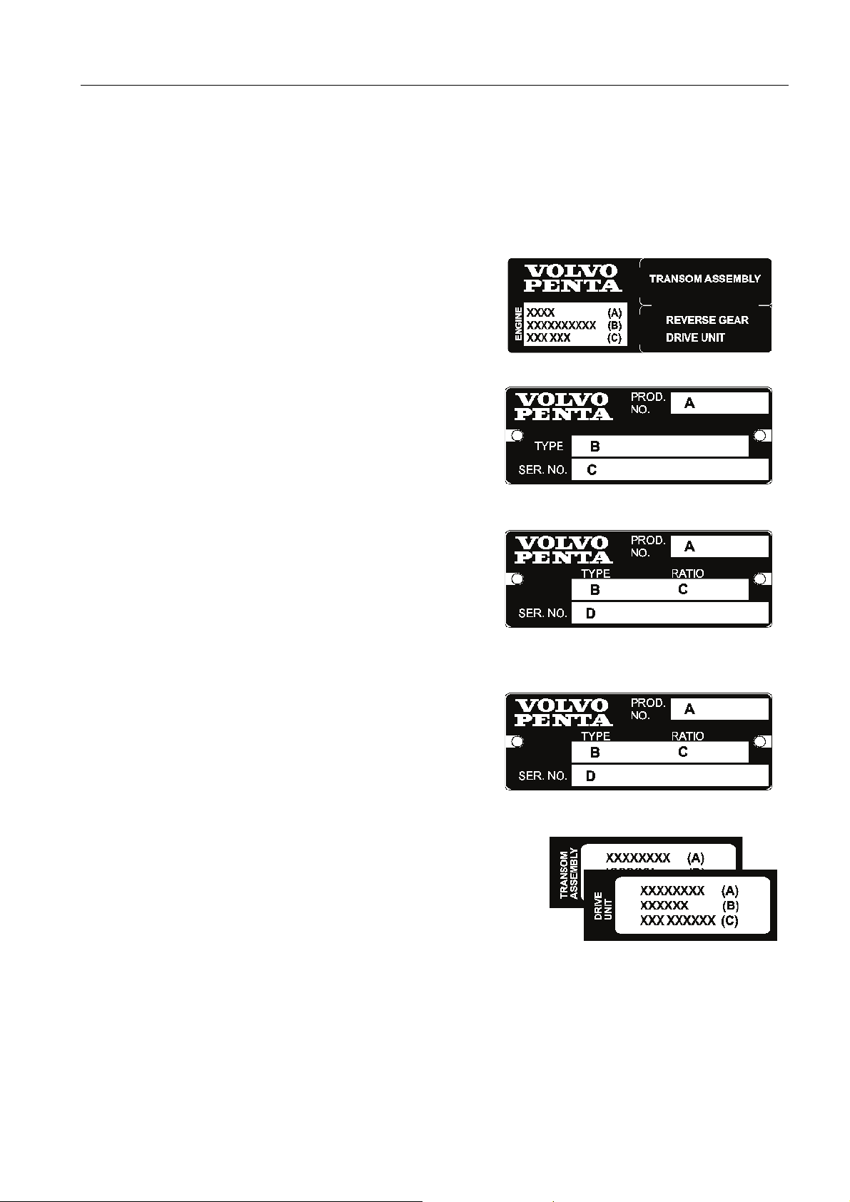
General Information
Identification Numbers
Always provide the engine, transom shield, and drive identification numbers when ordering service or replacement
components. The engine identification numbers are on informational decals located in the spots described on the
previous page. Make a note of the information on the lines provided below. Make a copy of this page and store
the information so that it is available in event of the boat being stolen.
Engine - Decal
Product Designation (A) ..............................................................
Specification No. (B) ...................................................................
Serial No. (C) ..............................................................................
Engine - Plate
Product No. (A) ...........................................................................
Type (B) .......................................................................................
Serial No. (C) ..............................................................................
Transom Shield Plate
Product No. (A) ...........................................................................
Type (B) .......................................................................................
Ratio (C) ......................................................................................
Serial No. (D) ..............................................................................
Drive
Product No. (A) ...........................................................................
Type (B) .......................................................................................
Ratio (C) ......................................................................................
22772
22774
22778
Serial No. (D) ..............................................................................
22778
Transom Assembly & Drive Unit Stickers
22779
Product Designation (A) .................................... /...................................
Specification No. (B) .................................. /..........................................
Serial No. (C) .......................................... /............................................
22780
The Transom Assembly & Drive Unit Stickers shown above should be located on the Engine Decal. Your Volvo
Penta dealer will have attached these stickers at the time that the transom assembly and drive unit were mounted
on your boat and attached to the engine.
VPA 7748131 English 09-2007 19
Page 26

General Information
Owner’s Identification Card
When you purchased your boat the dealer was required to register your power package with Volvo Penta. Your
dealer should provide you with proof of ownership in the form of an Owner's Registration Card or a print-out of the
Volvo Penta computer on-line registration screen. This provides proof of ownership and is required to validate
warranty, should warranty service become necessary. Warranty coverage may be delayed until the warranty and
registration form is on file at Volvo Penta.
Service, Replacement Parts, and Accessories
Genuine Volvo Penta parts are the result of many hours of strenuous testing and fulfill Volvo Penta’s strict quality
and safety requirements. Also, Volvo Penta marine engines are designed for high operational reliability and a long
service life. They are manufactured to withstand the marine environment while also affecting it as little as possible.
Through regular service and the use of Volvo Penta original spare parts, these qualities will be retained.
When replacements are required, use only Volvo Penta genuine parts. Always follow the maintenance intervals
contained in the operator’s manual. Remember to state the engine/transmission identification number when
ordering service and replacement parts.
Purchase all Volvo Penta replacement parts, accessories, coolants, and lubricants from an authorized Volvo Penta
dealer. The dealer has needed parts in stock for routine maintenance, as well as the information needed to order
special parts and accessories for you.
20 VPA 7748131 English 09-2007
Page 27
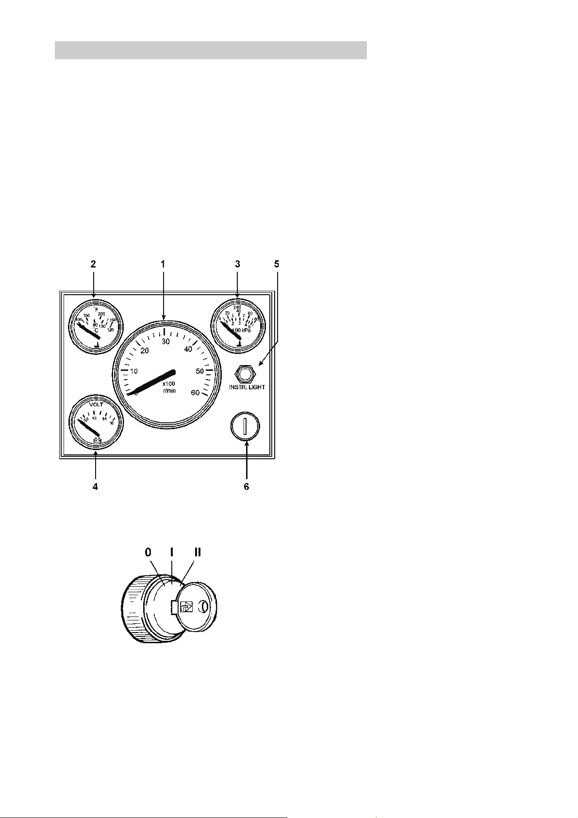
Instrumentation
Instrumentation
Instrument Panel
The following section contains a general description of the instrument panel. Please note that instrument panels
are installed by the boat builder and will vary depending on the model installed. Commonly, instrument panels are
equipped with a tachometer, temperature gauge, oil pressure gauge, voltmeter, instrument panel lighting switch,
and an ignition switch.
Instruments and ignition switches can also be supplemented with extra Volvo Penta instruments such as:
synchronization tachometers, fuel gauge, fresh water gauge, clock, speed log, or rudder indicator.
Note that the instrument cluster which is shown here installed in the instrument panels can be installed in other
positions on some boats. If your boat is fitted with instruments not described here and you are not sure of their
function, please get in touch with your boat dealer.
NOTICE! The instrument panel depicted below is a
sample representation only.
21179
1. Tachometer—Shows the engine RPM rate. Multiply this value by 100 or 1000 (depending on model) for
revolutions per minute. Integral “Hours run” meter (optional and separately installed) displays the engine’s
operating time in hours and tenths of an hour.
2. Temperature Gauge—Indicates engine temperature. Normal operating temperature for all 5.0–5.7L
engines is 155°-178°F (68°-81°C) and 135°-158°F
(57°-70°C) for 8.1L engines. Engines with closed cooling systems will typically run about 30°F (17°C) higher.
3. Oil Pressure Gauge—Indicates the engine oil
pressure. Normal operating oil pressure should be approximately 18 psi (124 kPa) minimum at 2000 RPM
on a warm engine. Lower oil pressure is normal and
should be expected at idle after a sustained cruise.
4. Voltmeter—Indicates the charge voltage from the
alternator which should normally be approximately 14
Volts. With the engine stopped and the switch on, battery voltage is normally indicated as 12 Volts.
5. Instrument Lighting—On Volvo Penta instrument
panels, turns panel lights on or off (varies, depending
on product manufacturer).
6. Ignition Switch—The ignition switch has three positions (varies, depending on product manufacturer):
0 The key can be inserted or removed.
I RUN: Ignition is ON and engine is OFF. System
voltage connected.
II START position (momentary). The starter mo-
tor is engaged and starting the engine.
NOTICE! Read the starting instructions in the section
21181
The ignition keys are marked with a code for use when
ordering extra keys (varies, depending on product
manufacturer). Record the code so that replacement
keys can be ordered. Keep the code in a safe place
where unauthorized persons do not have access to it.
VPA 7748131 English 09-2007 21
entitled Starting the Engine on page 34.
Page 28
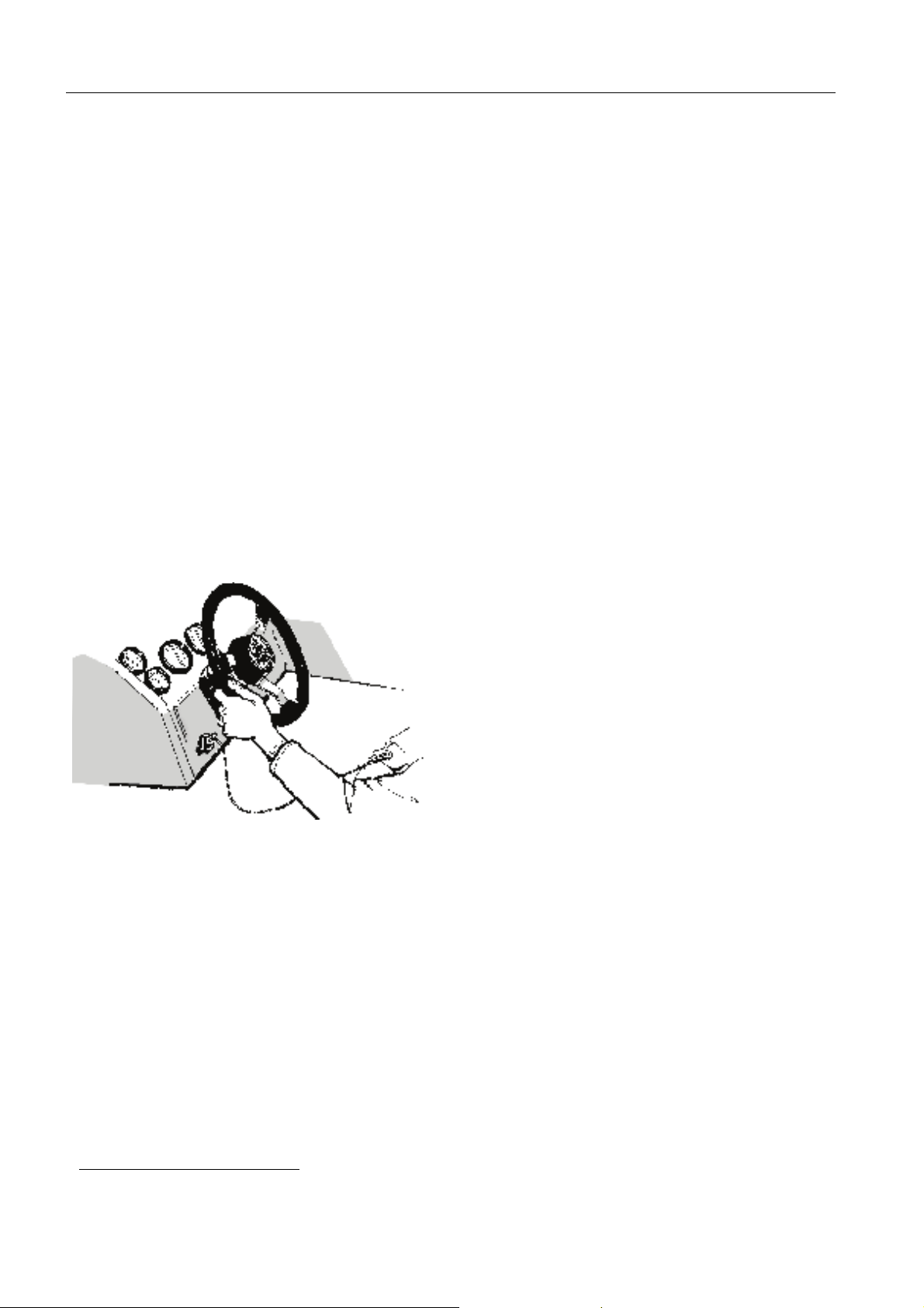
Instrumentation
Audible Alarm
If an audible alarm1 has been installed on your boat, it
will perform a brief self-test when the ignition key is
turned to the RUN position. Following is a description
of how the alarm performs the self test.
EFI Engines - When the ignition switch is turned to
RUN (key on, engine off), the alarm emits three short
beeps to indicate that the ECM is performing a check
of the sensors. If there are any problems detected by
the ECM, the alarm will sound; otherwise, it will remain off.
Emergency Stop Switch
An emergency stop switch, also called a safety breaker, may be a feature of your boat. Use of this switch is
highly recommended. To properly use this feature, attach the lanyard to clothing that will NOT tear away
before the lanyard is pulled from the switch to stop the
engine. If the lanyard is too long, shorten it by knotting
or looping it. DO NOT cut and re-tie the lanyard.
21182
The emergency stop switch can only be effective
when in good working order. Observe the following:
• Lanyard must always be free of entanglements
that could hinder its operation.
• Once a month, check the switch for proper oper-
ation. With engine running at idle speed, pull
lanyard. If engine does not stop, see your dealer
for repairs.
Using this switch is simple and should not interfere
with normal operation of the boat. Care must be tak-
en to avoid accidentally pulling the lanyard during
boat operation. Unexpected loss of forward motion will occur, as well as possible damage to the
engine. This could cause occupants to be thrown for-
ward. In an emergency situation, any occupant of the
boat may attempt to restart the engine by pressing in
and holding the emergency stop switch button, followed by normal starting procedures. When the button
is released, the engine will stop.
If your boat is not equipped with an emergency stop
switch and it falls into one of the following categories,
installation of an emergency stop switch is recommended.
• High performance sport boats
• Small runabouts
• Boats with sensitive steering
• Boats where the distance from the top of the
gunwale down to the driver’s seat is less than
one foot (30 cm).
Contact your Volvo Penta dealer for installation of an
emergency stop switch.
1. While Volvo Penta provides an audible alarm with every engine, its installation is determined by the manufacturer of your boat. If your
boat does not have an audible alarm available, we strongly recommend that you contact your dealer to have one installed.
22 VPA 7748131 English 09-2007
Page 29
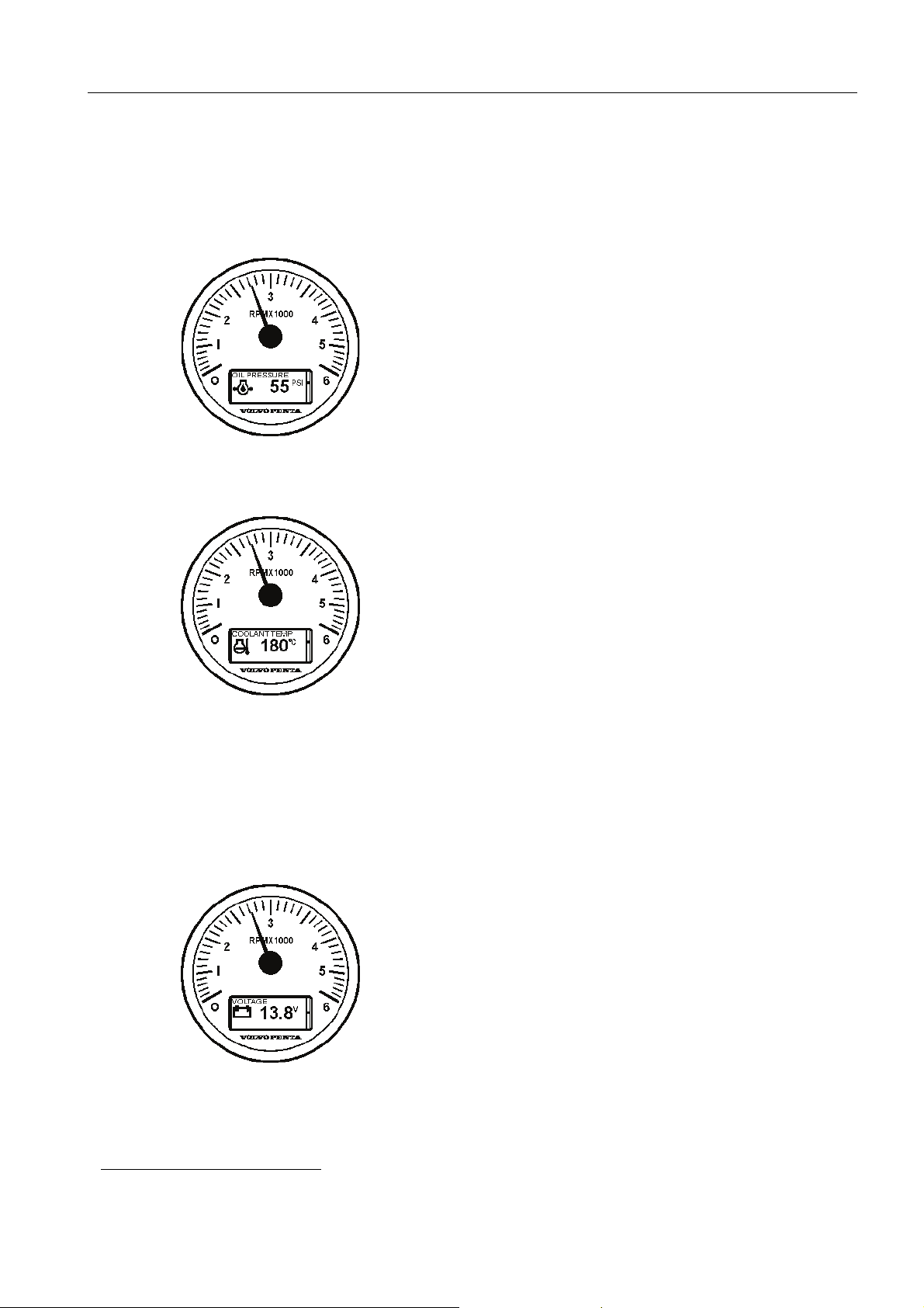
51274c
Instrumentation
Checking Instruments
Check instruments regularly. Stop the engine if there
is an abnormal reading or if the engine alarm sounds.
Oil Pressure
All engines have what is considered a normal operating oil pressure range. At engine idle this is normally
lower than at higher RPMs. For the normal operating
oil pressure range for your model engine, please refer
to the section entitled Technical Data on page 115.
Your boat is equipped with an audible low oil pressure
1
alarm
.
NOTICE! If oil pressure is too low: Stop the engine
immediately and investigate. Operating the
engine with oil pressure too low will damage the engine.
Engine Coolant Temperature
All engines have what is considered a normal operating temperature range. At engine idle this is normally
lower than at higher RPMs. Normal operating temperature for all 5.0–5.7L engines is 155°-178°F
(68°-81°C) and 135°-158°F (57°-70°C) for 8.1L engines. Engines with closed cooling systems will typically run about 30°F (17°C) higher.
51274d
51274e
Your engine is equipped with an engine coolant and
exhaust temperature acoustic alarm
1
.
NOTICE! If engine coolant or exhaust temperature is
too high: Idle the engine, shift to reverse
and then to forward. Idle the engine for 2 to
3 minutes and shut off the engine if the temperature does not decrease. Investigate
and correct the malfunction. Operating an
engine with temperatures too high will damage the engine.
Voltage/Charge
The operating charge is approximately 14 V. When the
engine is stopped and ignition is on, battery voltage is
approximately 12 V. With the ignition turned off, the
voltmeter will not register a charge.
1. While Volvo Penta provides an audible alarm with every engine, its installation is determined by the manufacturer of your boat. If your
boat does not have an audible alarm available, we strongly recommend that you contact your dealer to have one installed.
VPA 7748131 English 09-2007 23
Page 30

Instrumentation
Power Trim/Tilt
Your Volvo Penta sterndrive is equipped with a power
trim/tilt system as standard equipment. The power
trim/tilt allows you to change the angle of the drive unit
from the helm. Changing the angle of the drive unit in
relation to the boat bottom is called trimming. Trimming provides these benefits:
• Improves acceleration to planing.
• Keeps the boat on plane at reduced throttle set-
tings.
• Improves fuel economy.
• Provides smoother and/or drier ride in choppy
water conditions.
• Increases maximum speed.
If you do not wish to use this feature, you may leave
the drive unit trimmed to the position that works best
for you.
22781
22782
Trim Instruments
The trim instrument indicates the current trim position.
Your boat may be equipped with an analog or a digital
trim instrument.
Analog Trim Instrument
The analog trim instrument has three main ranges:
• Trim Range–Use trim range for maximum com-
fort, under normal operation, from start to maximum speed.
• Beach Range–Use beach range for operating at
reduced speed in shallow water, where water
depth is uncertain. Also use this range when you
launch and take your boat out of water onto a
trailer ramp.
• Lift Range–Use lift range for lifting the drive to
its maximum angle; however, this range cannot
be used during boat operation. Use this range
ONLY when you are transporting your boat.
CAUTION! Operating in beach range or lift
range will cause significant loss of maneuverability.
NOTICE! The maximum safe engine speed in the
Beach Range is 1000 RPMs. Operating in
beach range above idle speed, or for prolonged periods of time, may cause serious
drive damage. Always check that the cooling water intake is below the surface of the
water when running in Beach Range.
22783
24 VPA 7748131 English 09-2007
Page 31

Instrumentation
Trim/Tilt Motor Protection
NOTICE! Always allow the trim/tilt switch to return to its center position when the drive unit reaches its maximum
raised or lowered position. This precaution will prevent your trim/tilt motor from overheating.
Impact Protection
The trim/tilt system provides impact protection in the trim/tilt cylinders. If an impact occurs while in forward motion,
the cylinders will allow the drive to “kick up,” thereby helping to minimize drive damage. However, impact damage
can occur in either FORWARD or REVERSE directions.
NOTICE! When backing-up in REVERSE, there is no impact protection. Be very careful when backing-up in RE-
VERSE. Do not exceed 2500 RPM.
You must be careful when:
• You operate in FORWARD or REVERSE.
• You are backing up.
• You trailer your boat.
• You launch your boat.
NOTICE! Impact damage is more likely to occur when
you are in a turn where side loads are
placed on the drive unit.
50406
If you strike a solid object:
• Throttle back and shut off the engine immedi-
ately.
• Closely inspect the boat and drive unit (espe-
cially the transom shield assembly that contains
steering system components).
• Check the engine compartment for water leak-
age.
If there is damage, operate the boat at low RPM and
take it to a Volvo Penta dealer for inspection. Operating a damaged unit could cause additional damage
and could become very costly to repair. Have necessary repairs made immediately. Only operate your
boat if absolutely necessary.
NOTICE! Always check your boat and engine for
damage. Failure to inspect for damage
may:
• Result in sudden loss of steering control.
• Adversely affect your boat’s capability to resist
high-speed impacts.
22392
VPA 7748131 English 09-2007 25
Page 32

Instrumentation
Engine Protection Mode
In a low oil pressure, low voltage, engine overheat, or lack of exhaust cooling water situation, the Electronic Fuel
Injection (EFI) system will enter an Engine Protection Mode (EPM). In such cases, if an acoustic alarm has been
installed with your engine, the alarm will sound to notify you of a malfunction.
Under these conditions, engine operation is limited to
2500 RPMs or less. When the engine enters EPM,
there will be a temporary reduction in power until the
problem is resolved. We strongly urge you to bring
the engine to idle to investigate the problem. If the
acoustic alarm stops sounding, the malfunction has
been cleared and the engine may now be operated
normally.
If you are unable to locate and resolve the problem,
you may continue to operate the engine at above idle
speed, keeping in mind that the acoustic alarm will
continue sounding and the engine speed will remain
below 2500 RPMs
NOTICE! Continuing to run the engine in engine pro-
tection mode without correcting the cause
may result in engine damage.
1
.
51279c
CAUTION! If a malfunction triggers the engine protection mode, the engine may either
return to idle or shut down, depending on the
engine equipment and circumstances.
Use the oil pressure and water temperature gauges to
verify a problem exists, then inspect the engine crankcase for proper oil level and check the water inlets for
obstructions. The low oil pressure/engine overheat
problem must be corrected before the engine will return to normal operation.
To reset the Engine Protection Mode after the problem is corrected, reduce engine speed to idle, allow
the engine to cool, and then continue with normal operation.
NOTICE! If the problem continues, contact your Vol-
vo Penta dealer and have the engine inspected.
Engine Control Module (ECM)
The engine control module (ECM) is designed to
maintain exhaust emission levels while maintaining
excellent drivability and fuel efficiency. The ECM controls the following conditions:
• Fuel, ignition, and idle air control.
• Knock sensor system.
• Various other discrete outputs.
Other Instruments
See your Volvo Penta dealer for additional accessories specifically designed for your Volvo Penta product.
1. In boats equipped with the Electronic Vessel Control system (EVC-ec), alarm handling is different. After the alarm is acknowledged,
the buzzer is turned off. Please refer to the appendix for additional information.
26 VPA 7748131 English 09-2007
Page 33

Controls
Controls
Remote Control Unit
Volvo Penta controls are available in single top-mount, twin top-mount, or single side-mount configurations. The
control levers have an adjustable friction brake and a neutral position switch to ensure that the engine cannot be
started when the drive is in gear.
Your boat may be equipped with remote controls other than those described below. If Volvo Penta controls are not
used, ask your dealer for operating instructions for the remote control used in your boat since operation and
function may differ from Volvo Penta remote controls.
Single Lever Control Operation
Both the gear shift release and engine speed control
are operated using the single lever (1).
N Neutral position (drive is disengaged and the
engine runs at idle speed).
F Drive/forward gear engaged for forward move-
ment (ahead).
R Drive/reverse gear engaged for backward
movement (astern).
T Throttle/engine speed control.
NOTICE! The engine can be started only if the drive
is in neutral.
51260
Shifting from Neutral
To move the remote control lever from the neutral detent position, simply move the control lever in the desired direction.
Disengaging the Shift Function
The gear shift can be disengaged so that the control
lever affects only the engine speed.
1. Move the control lever 2 to the neutral position N.
2. On the EVC control panel, press the NEUTRAL
BUTTON 9 in and hold it down while moving the
control lever forward to the shift position F.
3. Release the NEUTRAL BUTTON. The lever now
affects only the engine speed (RPMs). The
Neutral button LED flashes when in neutral
warm-up mode. When the lever is moved back to
neutral, gear shifting will function normally.
51264
VPA 7748131 English 09-2007 27
Page 34

Controls
Twin Unit Maneuvering
When leaving or approaching the dock, or for any
close maneuvering at slow speed, place the port engine control lever 3 in neutral N (on standby) and use
the starboard engine. The use of one control is very
effective and more convenient. In the event that the
starboard engine (which is being used for maneuvering) stops, you can immediately go to the port engine
(which has been on standby).
NOTICE! Both engines must be running during close
maneuvering or at slow speeds. If only one
engine is running, water may be forced
back through the underwater exhaust outlet
and cause serious engine damage. Do not
attempt to plane boat while operating on a
single engine; operating with a single engine at full throttle could cause engine or
transmission damage.
51259
51266a
Neutral Interlock Button
The neutral interlock button 1, available on the sidemount control only, prevents accidentally moving the
throttle out of neutral. This button must be depressed
to shift the throttle out of neutral.
To move the control lever away from neutral:
1. With the control handle in NEUTRAL, depress the
neutral interlock button 1.
2. While keeping the button pressed, move control
handle out of neutral in the desired direction.
Once the throttle is out of the neutral position, you
may release the button.
The neutral interlock will automatically re-engage
when the control handle is returned to the NEUTRAL
position.
28 VPA 7748131 English 09-2007
Page 35

Controls
Shifting between Forward and Reverse
• To go from forward to reverse, or reverse to for-
ward, always pause at neutral N and allow
engine speed to return to idle.
• After shifting is completed, continue to move the
control handle slowly in the desired direction to
increase speed.
NOTICE! Do not shift gears if engine speed is above
800 RPM. Do not shift from forward to reverse when boat is planing. There is a danger that water will get into the engine and
cause serious damage, while causing serious damage to the drive.
CAUTION! Any time the boat is operated, be
aware of changes in shift system operation. A
sudden increase in shift effort at the remote
control handle, or other abnormal operation,
indicates a possible problem in the shift system. If you suspect there is a problem, see
your Volvo Penta dealer as soon as possible
for proper diagnosis and required service or
adjustment. Continued operation could result
in damage to the shift mechanism and loss of
shift and throttle control that could result in
personal injury.
51260
VPA 7748131 English 09-2007 29
Page 36

Controls
Engine WOT Range (RPM)
5.0 GXiE-J(F) 4600–5000
5.0 OSiE-J(F) 4600–5000
5.7 GiE300-J(F) 4600–5000
5.7 GXiE-J(F) 4800–5200
5.7 OSiE300-J(F) 4600–5000
5.7 OSXiE-J(F) 4800–5200
8.1 GiE-J(F) 4200–4600
8.1 GXiE-J(F) 4600–5000
8.1 OSiE-J(F) 4200–4600
Cruising Speed
Operating the engine at wide open throttle (WOT)
should be avoided since it is both uneconomical and
uncomfortable. Volvo Penta recommends a cruising
speed 25% lower than maximum RPM at WOT. Depending on hull type, choice of propeller, load and
conditions, etc., the maximum engine speed at top
speed can vary, but it should be within the WOT range.
How to Shift and Control Speed
If your boat is equipped with a non-Volvo Penta remote control system, ask your dealer how to properly
operate it.
51260
NOTICE! Verify proper functionality of all control and
engine systems before leaving the dock.
1. Move control handle(s) to the neutral detent position N. Check in front and behind boat for people
or obstructions before shifting.
2. To go forward: Move the control handle forward
from neutral detent to forward gear engagement
detent position F. Throttle movement will begin
after the detent position for forward gear
engagement. After the throttle is activated,
continue to move the control handle slowly in the
desired direction to increase speed.
3. To go in reverse: Move the control handle
backward until you reach the detent position for
reverse gear engagement R. Throttle movement
will begin after reverse gear engagement. After
the throttle is activated, continue to move the
control handle slowly in the desired direction to
increase speed.
NOTICE! Do not shift gears if engine speed is above
800 RPM.
30 VPA 7748131 English 09-2007
Page 37

16783
Controls
Trim Controls
Trimming (raising and lowering the drive) can be performed by using:
• A separate control panel (shown at left) on the
instrument panel.
• A control button 2 on the single control lever.
• The control buttons 4 & 5 on the port control
lever in a twin installation.
The current trim position is indicated on a trim gauge
located on the instrument panel, in the tachometer
LCD display, or elsewhere on the dashboard.
Operating Trim Controls
Control Panel
The control panel has two standard buttons for tilt control:
51266
• The top button moves the drive trim out while
raising the boat’s bow.
• The lower button moves the drive trim in while
lowering the boat’s bow.
Remote Control Lever
The control button on the control lever has two functions:
• Pressing the top half of the button moves the
drive trim out while raising the boat’s bow.
• Pressing the bottom half of the button moves the
drive trim in while lowering the boat’s bow.
51267
VPA 7748131 English 09-2007 31
Page 38

Controls
Friction Brake
The remote control has a friction brake, which can be adjusted as necessary, to provide lighter or heavier lever
action. If you are using a Volvo Penta shift control and you wish to make adjustments to the friction brake, follow
the instructions below to make the necessary changes.
NOTICE! Each manufacturer has a particular method for making adjustments to the friction brake. For specific
directions on how to adjust a non-Volvo Penta friction brake, please refer to your manufacturer’s manual.
NOTICE! The brake must only be adjusted when the control lever is in the throttle range. Do not adjust the friction
with the control in neutral.
Side Mount Remote Controls
1. Make sure the engine is turned off by removing
the key from the ignition switch.
2. Remove the plastic cover that shields the remote
control mechanism.
3. Place the control lever in reverse (just beyond the
reverse detent position) and adjust the throttle
brake screw to prevent throttle creep.
51263
4. Turn the tension screw B clockwise to increase
drag and counter-clockwise to decrease drag on
the control arm.
5. Reinstall the plastic cover and remote control
lever.
Top Mount Remote Controls
1. Make sure the engine is turned off by removing
the key from the ignition switch.
2. Remove the plastic cover that shields the remote
control mechanism.
3. For single lever controls, move the throttle to the
forward position. For dual lever controls, move the
port side lever forward and the starboard side
lever into reverse.
4. Turn the tension screw A clockwise to increase
drag and counter-clockwise to decrease drag on
the control arm.
5. Reinstall the plastic cover and remote control
lever.
51262
32 VPA 7748131 English 09-2007
Page 39

Operation
Operation
Operating the Engine
NOTICE! Do not start the engine out of the water unless you have connected a hose with running water to the
flushing adapter. Please refer to the section entitled Engine Flush on page 80 for instructions on attaching and running the engine out of water.
Thoroughly familiarize yourself with the operation of the remote control supplied with your boat, then proceed as
follows.
Before Starting
DANGER! To prevent a possible explosion
hazard, operate the engine compartment or
bilge blower as recommended by the boat
21192
21190
manufacturer before starting the engine. If
the engine compartment is not equipped with
a blower, open the engine cover or hatch before starting so as to disperse any gasoline
fumes that may be present. Leave the hatch
open until after the engine is running.
1. Start the boat’s bilge blower and run as recommended by the boat manufacturer. Frequently
check boat’s bilge area for gasoline fumes.
51216
21181
2. Check the bilge for excessive water accumulation. Always keep the bilge clean and dry.
NOTICE! The water level in the boat’s bilge will in-
crease when you operate your boat at a
high incline before you reach planing
speed. Excessive water in the bilge can
cause engine damage.
3. Open the fuel cock A. Also, ensure that the sea
cock is open–if so equipped.
4. Make sure that there are no fuel, engine coolant,
or oil leaks B.
5. Check engine oil level C. Level must be between
D and E. Note: The oil level may be higher than D
at start up.
6. If equipped, turn on the main battery switches.
7. Insert the key into the ignition switch O. Turn the
key one step to the right I to switch on engine
system voltage and instrumentation.
8. Make sure that the fuel gauge is operating and
that you have enough gasoline F.
51274f
VPA 7748131 English 09-2007 33
Page 40

Operation
9. Lower the drive unit to normal run position; make
sure the water intakes are submerged. There
should be no obstructions in the water near the
propellers.
50404
22392-1
51260a
Starting the Engine
EVC-ec engines are equipped with an auto-crank feature. Momentarily turning the key to the start position,
then releasing it back to the ON position I will cause
the engine to continue to crank for up to 5 seconds or
until the engine starts.
If you attempt to execute a "fast crank" (turning the key
from OFF immediately all the way to START), there
will be a 3–5 second delay while EVC "warms up."
1. Move the control handle to the neutral detent
position N.
2. Turn the ignition switch to START II. If the engine
does not start, then try again.
NOTICE! If engine cranking needs to be aborted, the
key can be turned to the OFF position 0.
NOTICE! Never leave the key in the ON position with
the engine not running.
NOTICE! If the engine floods during a warm start,
simply follow the directions provided in the
section entitled If the Engine Floods on
page 35 to restart the engine.
21181
34 VPA 7748131 English 09-2007
Page 41

51260b
Operation
If the Engine Floods
1. Turn the key to ON or RUN I.
2. On the EVC control panel, press and hold the
NEUTRAL BUTTON 9 while moving the control
lever 2 forward to the shift position F.
3. Let go of the NEUTRAL BUTTON and move the
remote control lever to FULL THROTTLE T.
NOTICE! Be prepared to quickly move the control
handle to IDLE once the engine starts. This
will avoid over-speeding and possibly damaging the engine.
4. Turn the ignition switch to START II. If the engine
does not start, then try again.
NOTICE! After a second attempt, if the engine still
does not start, return the control lever to
the neutral position and try a normal engine start.
51264
21181
5. As soon as the engine starts:
• Return the remote control handle to IDLE.
• Return the key to ON or RUN I.
NOTICE! Immediately after engine start-up, look at all
instruments. If any readings are abnormal,
stop the engine and determine the cause.
Stopping the Engine
1. Move the remote control lever to NEUTRAL N.
2. Let engine return to idle.
3. Turn ignition key to OFF 0.
NOTICE! Do not stop the engine at speeds above idle
or “speed up” the engine while turning off
the ignition. Do not stop the engine while in
gear or while the boat is moving. Engine
damage could result from water being
sucked back up through the exhaust ports.
VPA 7748131 English 09-2007 35
Page 42

Operation
Steering System Operation
The steering system for your Volvo Penta sterndrive is operated by a steering cable connected to the helm.
Restricting movement of the steering cable will limit or stop the steering system’s hydraulic assist.
Do not interfere with or restrict steering cable movement through the last 90° of bend at the engine. Do not use
cable retainers, clamps, or tie straps. Using one or all of these could restrict the cable movement near the engine.
Do not tie wiring harnesses or other control cables to the steering cable. Make sure deck combing and bulkheads
allow for steering cable movement.
If the power steering system stops working, it will feel
harder to steer. If this condition occurs, look for possible causes and fix them if possible. If the power steering system cannot be corrected on board, proceed at
a reduced speed. You will be able to steer the boat, but
with increased effort. See your authorized Volvo Penta
dealer as soon as possible to correct your power
steering system.
At slow speeds (no wake), your boat may tend to wander. This is normal and may be overcome by anticipating bow direction and correcting with steering wheel.
A slightly higher throttle and trim setting may also lessen the tendency to “wander.” Changing weight distri-
21182
bution, aft to forward, can also affect slow speed
steering.
50405
Twin Unit Steering
Twin engine boats may have only one engine with a
fully operational power steering system. That power
steering system is on the starboard engine; therefore,
when operating on a single engine use the starboard
engine.
Using a port engine that does not have a functional
power steering system will cause an increased effort
in steering control, due to absence of power assist.
NOTICE! Both engines must be running during close
maneuvering or at slow speeds. If only one
engine is running, water may be forced
back through the underwater exhaust outlet
and cause serious engine damage. Do not
attempt to plane boat while operating on a
single engine; operating with a single engine at full throttle could cause engine or
transmission damage.
36 VPA 7748131 English 09-2007
Page 43

Operation
Power Trim and Tilt Operation
Trimming and tilting the drive is done from a control switch mounted on the remote control (2, 4, 5) or by using the
switches on the dash (shown below). When using the dash mounted switches, the bottom button lowers the bow
and the top button raises the bow. The switch on the remote control lever raises and lowers the drive when its upper
or lower segment is pressed.
NOTICE! Allow the trim/tilt switch to return to its cent-
er position when the drive unit reaches the
maximum raised or lowered position. This
will prevent your trim/tilt motor from overheating.
The trim/tilt motor is protected from overheating by an
internal thermal overload switch. If the electric motor
stops while tilting, release the switch and allow the
overload switch to cool and automatically reset itself.
When the overload switch has reset, tilting may be resumed. Make sure the drive unit is not being re-
16783
strained, causing the motor to overheat. If the electric
motor still does not operate, check the 40-amp
breaker located in the fuse box.
For additional information about Trim and Tilt controls,
please refer to Controls on page 27 and Power Trim
on page 143.
1
circuit
51266
Power Trim Operation
The power trim is normally used before you accelerate
onto plane, after you reach the desired RPM or boat
speed, and when there is a change in water or boating
conditions. Locate passengers and equipment in the
boat so that the weight is balanced fore and aft, and
side to side. Trimming will not cancel an unbalanced
load.
To operate the trim, push and hold the switch “bow-up”
or “bow-down” until the desired bow position is
reached. The trim may be operated at any boat speed
or at rest. Avoid operating the trim system when running in reverse.
Observe the trim/tilt gauge, which indicates the bow
position achieved. The upper scale of the trim gauge
indicates the “bow-up” positions, and lower scale of
the trim gauge indicates the “bow-down” positions.
For additional information, see Determining the Prop-
er Trim on page 38.
51267
VPA 7748131 English 09-2007 37
1. 50-amp on Ocean Series (OSi) engines.
Page 44

Operation
16783
Determining the Proper Trim
The effect of the maximum “bow-up” and “bow-down”
positions will be similar for most boats. The bow position best for your operating conditions could be at any
trim setting between the maximum “bow-up” and
“bow-down” positions.
The boat will be properly trimmed when the trim angle
provides the best boat performance for your operating
conditions. On models without power steering, the
trim position that provides a balanced steering load is
desirable.
To familiarize yourself with the power trim, make test
runs at slower speeds and at various trim positions to
see the effect of trimming. Note the time it takes for the
boat to plane. Watch the tachometer and speedometer readings and the ride action of the boat.
The following sections entitled Operating in “Bow-up”
Position and Operating in “Bow-down” Position provide additional information on this topic.
22796
Operating in “Bow-up” Position
The “bow-up” A position is normally used for cruising,
running with a choppy wave condition, or running at
full speed. In a full “bow-up” position the boat may
tend to self-steer. You may have to compensate with
the steering wheel to keep the boat in a straight-ahead
path. In this position the boat’s bow will tend to raise
clear of the water. Excessive “bow-up” trim will cause
propeller ventilation resulting in propeller slippage.
Engine RPM will also increase, but boat speed will not
increase and may even drop.
CAUTION! Use caution when operating in
rough water or crossing another boat’s wake.
Excessive “bow-up” trim may result in the
boat’s bow rising rapidly and possibly throwing the boat’s occupants into the water.
38 VPA 7748131 English 09-2007
Page 45

22797
Operation
Operating in “Bow-down” Position
The “bow-down” B position is normally used for acceleration onto plane, operating at slow planing speeds,
and running against a choppy wave condition. In the
fully “bow-down” position the boat may tend to selfsteer. You may have to compensate with the steering
wheel to keep the boat in a straight-ahead path. In this
position the boat’s bow will tend to go deeper into the
water. If the boat is operated at high speed and/or
against high waves, the bow of the boat will plow into
the water. The boat may tend to bow steer or spin
about rapidly and possibly eject occupants.
NOTICE! The boat trim should be adjusted to provide
balanced steering as soon as possible each
time you get underway. Some boat, engine,
and propeller combinations may encounter
boat instability and/or high steering torque
when operated at or near the limits of the
“bow-up” or “bow-down” positions. Boat stability and steering torque can also vary due
to changing water conditions. If you experience boat instability and/or high steering
torque, see your Volvo Penta dealer to correct these conditions.
Power Tilt Operation
Tilting is normally used for raising the drive unit to obtain clearance when beaching, launching from a trailer, or
mooring. When tilting the drive unit, the boat should be at rest or at idle speed only.
The trim/tilt switch controls the tilting feature of the drive unit. When the trim/tilt switch is held in the “bow-up”
position, the drive unit tilts up until the switch is released or the drive unit reaches the maximum tilt position.
NOTICE! Never exceed 1000 RPM when operating the drive unit in the tilted position because it may damage the
drive system. Never RUN the engine when the drive unit is tilted more than 30° or the drive will be damaged.
Never operate the engine out of water or without water supplied to the engine. The water pump may be damaged
or the engine may overheat. For additional information, see Engine Flush on page 80.
WARNING! To avoid possible contact with the propellers, never use the drive unit as a ladder or as a
lift to board the boat. Never board at the rear of the boat when the engine is running, even if the engine
is operating in neutral. Personal injury could result from contact with rotating engine parts and propellers.
Any malfunction of the trim/tilt system could result in a loss of impact protection. Malfunction can also result in loss
of reverse thrust capability. If a malfunction occurs, see your authorized Volvo Penta dealer.
Power Trim/Tilt Switch & Gauge Location
The power trim/tilt switch is located on the remote control handle or on the boat’s dashboard. The trim indicator
displays the drive position in the Trim range. With dual installations, it is permissible to individually trim the drive in
Trim range. When the drive is in Beach range, boat speed must be lower than planing speed. The engine must be
stopped when fully tilted (Lift Range).
VPA 7748131 English 09-2007 39
Page 46

Operation
Special Boating Situations
The following section covers scenarios that are considered special boating situations. When using the boat in the
following situations, there are some special procedures to take into consideration in order to keep the engine,
transmission, drive, and propeller in top working condition.
Shallow Water Operation
You may tilt the drive unit to reduce the draft for shallow water running A as long as you do not exceed
1000 RPM. Exceeding 1000 RPM is not necessary. It
will only increase the boat wake and will not increase
boat speed appreciably.
NOTICE! Exceeding 1000 RPM with the drive unit tilt-
ed could damage drive train components.
This type of damage is not covered by warranty. Never attempt to plane the boat or ex-
22798
ceed 1000 rpm with the drive unit in a
partially tilted position. Always return to the
trim range as soon as possible to avoid
damage to drive train. Never RUN the engine with the drive unit tilted more than 30°
or the drive will be damaged.
When operating in shallow water, be sure the water intakes located in the lower gear unit are submerged at
all times. Proceed at slow speed and lower drive unit
immediately when deeper water is reached.
NOTICE! Be very careful when operating in shallow
water; the intakes may pick up mud, sand,
underwater vegetation, or other submerged
debris. This may lead to overheating and
engine damage.
High Altitude Operation
Volvo Penta EFI engines have programmed altitude
compensation; however, there may be a slight performance loss at altitudes above 5000 feet due to lower air density. If you are boating above 5000 feet for a
short time, a lower pitch propeller will restore some of
the lost performance. Long term use above altitudes
of 5000 ft. may require a change in gear ratio which is
not covered under the Volvo Penta Limited Warranty.
22799
40 VPA 7748131 English 09-2007
Page 47

Operation
Operating in Freezing Temperatures
When freezing temperatures are forecast and the boat
will be operated and left in the water, the drive unit
must remain in the tilted down (submerged) position at
all times to prevent water in the drive unit from freezing. Upon completion of engine operation, drain the
engine as described in the maintenance section of this
manual.
21199
22800
Salt Water Operation
You can use your Volvo Penta sterndrive in either fresh
or salt water.
We recommend that you use fresh water to flush out
the engine and drive as described in the maintenance
section of this manual after you use it in polluted or
salt water. This will prolong the service life of the manifolds and risers. For additional information, see En-
gine Flush on page 80.
Trailering Your Boat
If your boat will be trailered, tilt the drive unit out of the
water. After you remove your boat from the water, lower the drive unit to the RUN (down) position until the
cooling system drains thoroughly.
Rinse the entire drive exterior with fresh water, then
dry it and spray it with anti-corrosion spray.
Before trailering your boat on the road, check the
ground clearance of the drive unit. When trailering, the
drive unit may be in the up or down position. There
must be at least 15 inches (38.1 cm) clearance between the lower gear unit and the ground. If the clearance is less than 15 inches (38.1 cm), raise the drive
unit.
NOTICE! Be very careful when you back out of drive-
ways or cross railroad tracks, so that the
sterndrive does not hit the ground.
Make sure that the boat fits the trailer properly. In
many cases, loss of performance and speed is due to
improper trailer support and too much tie-down pressure, which causes the boat bottom to deform. The
boat should rest firmly on the trailer with maximum tiedown pressure applied at the bow and transom only.
VPA 7748131 English 09-2007 41
Page 48

Operation
Notes
. . . . . . . . . . . . . . . . . . . . . . . . . . . . . . . . . . . . . . . . . . . . . . . . . . . . . . . . . . . . . . . . . . . . . . . . . . . . . . . . . . . . . . . . .
. . . . . . . . . . . . . . . . . . . . . . . . . . . . . . . . . . . . . . . . . . . . . . . . . . . . . . . . . . . . . . . . . . . . . . . . . . . . . . . . . . . . . . . . .
. . . . . . . . . . . . . . . . . . . . . . . . . . . . . . . . . . . . . . . . . . . . . . . . . . . . . . . . . . . . . . . . . . . . . . . . . . . . . . . . . . . . . . . . .
. . . . . . . . . . . . . . . . . . . . . . . . . . . . . . . . . . . . . . . . . . . . . . . . . . . . . . . . . . . . . . . . . . . . . . . . . . . . . . . . . . . . . . . . .
. . . . . . . . . . . . . . . . . . . . . . . . . . . . . . . . . . . . . . . . . . . . . . . . . . . . . . . . . . . . . . . . . . . . . . . . . . . . . . . . . . . . . . . . .
. . . . . . . . . . . . . . . . . . . . . . . . . . . . . . . . . . . . . . . . . . . . . . . . . . . . . . . . . . . . . . . . . . . . . . . . . . . . . . . . . . . . . . . . .
. . . . . . . . . . . . . . . . . . . . . . . . . . . . . . . . . . . . . . . . . . . . . . . . . . . . . . . . . . . . . . . . . . . . . . . . . . . . . . . . . . . . . . . . .
. . . . . . . . . . . . . . . . . . . . . . . . . . . . . . . . . . . . . . . . . . . . . . . . . . . . . . . . . . . . . . . . . . . . . . . . . . . . . . . . . . . . . . . . .
. . . . . . . . . . . . . . . . . . . . . . . . . . . . . . . . . . . . . . . . . . . . . . . . . . . . . . . . . . . . . . . . . . . . . . . . . . . . . . . . . . . . . . . . .
. . . . . . . . . . . . . . . . . . . . . . . . . . . . . . . . . . . . . . . . . . . . . . . . . . . . . . . . . . . . . . . . . . . . . . . . . . . . . . . . . . . . . . . . .
. . . . . . . . . . . . . . . . . . . . . . . . . . . . . . . . . . . . . . . . . . . . . . . . . . . . . . . . . . . . . . . . . . . . . . . . . . . . . . . . . . . . . . . . .
. . . . . . . . . . . . . . . . . . . . . . . . . . . . . . . . . . . . . . . . . . . . . . . . . . . . . . . . . . . . . . . . . . . . . . . . . . . . . . . . . . . . . . . . .
. . . . . . . . . . . . . . . . . . . . . . . . . . . . . . . . . . . . . . . . . . . . . . . . . . . . . . . . . . . . . . . . . . . . . . . . . . . . . . . . . . . . . . . . .
. . . . . . . . . . . . . . . . . . . . . . . . . . . . . . . . . . . . . . . . . . . . . . . . . . . . . . . . . . . . . . . . . . . . . . . . . . . . . . . . . . . . . . . . .
. . . . . . . . . . . . . . . . . . . . . . . . . . . . . . . . . . . . . . . . . . . . . . . . . . . . . . . . . . . . . . . . . . . . . . . . . . . . . . . . . . . . . . . . .
. . . . . . . . . . . . . . . . . . . . . . . . . . . . . . . . . . . . . . . . . . . . . . . . . . . . . . . . . . . . . . . . . . . . . . . . . . . . . . . . . . . . . . . . .
. . . . . . . . . . . . . . . . . . . . . . . . . . . . . . . . . . . . . . . . . . . . . . . . . . . . . . . . . . . . . . . . . . . . . . . . . . . . . . . . . . . . . . . . .
. . . . . . . . . . . . . . . . . . . . . . . . . . . . . . . . . . . . . . . . . . . . . . . . . . . . . . . . . . . . . . . . . . . . . . . . . . . . . . . . . . . . . . . . .
. . . . . . . . . . . . . . . . . . . . . . . . . . . . . . . . . . . . . . . . . . . . . . . . . . . . . . . . . . . . . . . . . . . . . . . . . . . . . . . . . . . . . . . . .
. . . . . . . . . . . . . . . . . . . . . . . . . . . . . . . . . . . . . . . . . . . . . . . . . . . . . . . . . . . . . . . . . . . . . . . . . . . . . . . . . . . . . . . . .
. . . . . . . . . . . . . . . . . . . . . . . . . . . . . . . . . . . . . . . . . . . . . . . . . . . . . . . . . . . . . . . . . . . . . . . . . . . . . . . . . . . . . . . . .
. . . . . . . . . . . . . . . . . . . . . . . . . . . . . . . . . . . . . . . . . . . . . . . . . . . . . . . . . . . . . . . . . . . . . . . . . . . . . . . . . . . . . . . . .
. . . . . . . . . . . . . . . . . . . . . . . . . . . . . . . . . . . . . . . . . . . . . . . . . . . . . . . . . . . . . . . . . . . . . . . . . . . . . . . . . . . . . . . . .
. . . . . . . . . . . . . . . . . . . . . . . . . . . . . . . . . . . . . . . . . . . . . . . . . . . . . . . . . . . . . . . . . . . . . . . . . . . . . . . . . . . . . . . . .
. . . . . . . . . . . . . . . . . . . . . . . . . . . . . . . . . . . . . . . . . . . . . . . . . . . . . . . . . . . . . . . . . . . . . . . . . . . . . . . . . . . . . . . . .
. . . . . . . . . . . . . . . . . . . . . . . . . . . . . . . . . . . . . . . . . . . . . . . . . . . . . . . . . . . . . . . . . . . . . . . . . . . . . . . . . . . . . . . . .
. . . . . . . . . . . . . . . . . . . . . . . . . . . . . . . . . . . . . . . . . . . . . . . . . . . . . . . . . . . . . . . . . . . . . . . . . . . . . . . . . . . . . . . . .
. . . . . . . . . . . . . . . . . . . . . . . . . . . . . . . . . . . . . . . . . . . . . . . . . . . . . . . . . . . . . . . . . . . . . . . . . . . . . . . . . . . . . . . . .
42 VPA 7748131 English 09-2007
Page 49

Features
Your Volvo Penta product consists of three components: the engine, transom shield and the sterndrive. There are
certain parts on each component that you, the owner, must take care of to make sure that your Volvo Penta product
stays in optimum running condition. The important parts of each component are shown in the illustrations on the
following “Features” pages. Explanations of these parts and systems are described below; the maintenance
procedures are found in the Maintenance section.
Features
Circuit Breakers and Fuses
Fuse and Relay Box Layout
Several spare fuses and relays are located on the inside of the fuse and relay box cover. In case of malfunctioning
or faulty fuses and relays, use the spares provided.
23672
A Trim Down Relay
B Trim Up Relay
C Starter Relay
D Fuel Pump Relay
E Ignition Relay
F1 15 Amp Fuse (EVC–Secondary)
F2 20 Amp Fuse (EVC–Primary)
F3 20 Amp Fuse (Fuel Pump)
F4 15 Amp Fuse (Ignition)
F5 5 Amp Fuse (Vessel Switch)
F6 20 Amp Fuse (ECM)
F7 40 Amp Fuse (Instrument Panel)
F8 40 Amp or 50 Amp Circuit Breaker (Trim Pump)
F9 20 Amp Fuse (Starter)
Legend of Symbols Used in Engine Photos
1 2 3 4 56789
22341 22874 22343 22342 22345 22372 22873 22346 22377
1 Engine Oil
2 Engine Oil Level
3 Power Steering Fluid
4 Sterndrive Oil
5 Engine Raw Water Drain
6 Engine Coolant Drain (Closed Cooling)
7 Engine Coolant
8 Running Engine Flush
9 Heat Exchanger Raw Water Drain
1
1. Ocean Series (OSi) engines require the use of a 50 Amp fuse. All other engines require a 40 Amp fuse.
VPA 7748131 English 09-2007 43
Page 50

Features
5.0GXiE-J(F), 5.0OSiE-J(F), 5.7GiE300-J(F), 5.7GXiE-J(F),
5.7OSiE300-J(F), 5.7OSXiE-J(F)
51300
1. Exhaust Risers
2. Exhaust Overheat Sensors
3. Powertrain Control Unit
4. Engine Control Unit
5. Engine Thermostat Housing
6. Flame Arrestor
7. Shift Actuator
8. Circuit Breakers, Fuses, and
Relays
9. Alternator
10. Oil Dipstick
11. Oil Siphon Tube
12. Engine Oil Filter Assembly
44 VPA 7748131 English 09-2007
13. Power Steering Fluid Fill
14. Serpentine Belt
15. Power Steering Pump
16. Raw Water Pump
17. Heat Exchanger
18. Anode
19. Engine Water Circulation
Pump
20. Fuel Pump (High Pressure)
21. Fuel Pump (Low Pressure)
22. Fuel Filter
23. Automatic Belt Tensioner
24. Running Engine Flush Port
25. Engine Coolant Fill
26. Spark Plugs
27. Oil Fill Cap
28. Exhaust Manifold Water Drain
29. Engine Raw Water Drain
30. Starter
31. Exhaust Manifold
32. Distributor
33. PCV Valve
1. Raw water cooled engines only
2. Not shown
2
1
Page 51

Features
51301
51302
VPA 7748131 English 09-2007 45
Page 52

Features
8.1GiE-J(F), 8.1GXiE-J(F), 8.1OSiE-J(F)
51303
1. Exhaust Risers
2. Exhaust Overheat Sensors
3. Engine Coolant Fill
4. Circuit Breakers, Fuses, and
Relays
5. Shift Actuator
6. Flame Arrestor
7. Powertrain Control Unit
8. Alternator
9. Engine Control Unit
10. Oil Dipstick
11. Oil Siphon Tube
46 VPA 7748131 English 09-2007
12. Engine Oil Filter Assembly
13. Power Steering Fluid Fill
14. Serpentine Belt
15. Power Steering Pump
16. Engine Oil Cooler
17. Raw Water Pump
18. Engine Water Circulation
Pump
19. Heat Exchanger
20. Fuel Pump (High Pressure)
21. Fuel Pump (Low Pressure)
22. Fuel Filter
23. Automatic Belt Tensioner
24. Engine Thermostat Housing
25. Running Engine Flush Port
26. Spark Plugs
27. Oil Fill Cap
28. Anode
29. Exhaust Manifold Water Drain
30. Engine Raw Water Drain
1
31. Starter
32. Exhaust Manifold
1. Raw water cooled engines only
Page 53

Features
51304
51305
VPA 7748131 English 09-2007 47
Page 54

Features
SX-A Sterndrive
50465
1. Oil Fill
2. Trim Sender
3. Trim Pump Oil Fill
1
4. Trim Pump
1. Trim pump oil is not a regular maintenance item. Please refer to the section entitled Power Trim/Tilt-Fluid: SX-A/DPS-A on page 88 for
additional information.
48 VPA 7748131 English 09-2007
5. Anodes
6. Pitot Tube
7. Raw Water Intake
8. Oil Drain
9. Propeller
10. Trim Cylinder
Page 55

DPS-A Sterndrive
Features
50397
1. Oil Fill
2. Trim Sender
3. Trim Pump Oil Fill
6. Pitot Tube
7. Raw Water Intake
1
8. Oil Drain
9. Front Propeller
10. Rear Propeller
11. Trim Cylinder
4. Trim Pump
5. Anodes
1. Trim pump oil is not a regular maintenance item. Please refer to the section entitled Power Trim/Tilt-Fluid: SX-A/DPS-A on page 88 for
additional information.
VPA 7748131 English 09-2007 49
Page 56

Features
XDP-B Sterndrive
23741
1. Oil Fill
2. Trim Sender
3. Anodes
1. A third anode (not shown) is located on the trim cylinder. See Replacing Anodes (XDP-B) on page 96.
50 VPA 7748131 English 09-2007
1
4. Raw Water Intake
5. Oil Drain
6. Rear Propeller
7. Front Propeller
Page 57

Engine Parts & Accessories
Maintenance Parts List
Maintenance Parts List
23179
5.0GXiE-J 3869446 8692305 3847302 3587597 3862228
5.0GXiE-JF 3869431 8692305 3847302 3831426 3862228
5.0OSiE-J 3869451 8692305 3847302 3587597 3862228
5.0OSiE-JF 3869432 8692305 3847302 3831426 3862228
5.7GiE300-J 3869447 8692305 3847302 3587597 3862228
5.7GiE300-JF 3869433 8692305 3847302 3831426 3862228
5.7GXiE-J 3869448 8692305 3847302 3587597 3862228
5.7GXiE-JF 3869435 8692305 3847302 3831426 3862228
5.7OSiE300-J 3869452 8692305 3847302 3587597 3862228
5.7OSiE300-JF 3869434 8692305 3847302 3831426 3862228
5.7OSXiE-J 3869453 8692305 3847302 3587597 3862228
5.7OSXiE-JF 3869436 8692305 3847302 3831426 3862228
8.1GiE-J 3869449 8692305 3847302 3853983 3862228
8.1GiE-JF 3869437 8692305 3847302 3831426 3862228
8.1GXiE-J 3869450 8692305 3847302 3853983 3862228
8.1GXiE-JF 3869439 8692305 3847302 3831426 3862228
8.1OSiE-J 3869454 8692305 3847302 3853983 3862228
8.1OSiE-JF 3869438 8692305 3847302 3831426 3862228
51218
23180
23177
23170
VPA 7748131 English 09-2007 51
Page 58

Maintentance Parts List
Engine Parts & Accessories (Continued)
23185
23179
23171
23184
23172-1
5.0GXiE-J 3869446 3842786 3858996 X 2 3858977 3858975
5.0GXiE-JF 3869431 3842786 3858996 X 2 3858977 3858975
5.0OSiE-J 3869451 3842786 3858996 X 2 3858977 3858975
5.0OSiE-JF 3869432 3842786 3858996 X 2 3858977 3858975
5.7GiE300-J 3869447 3842786 3858996 X 2 3858977 3858975
5.7GiE300-JF 3869433 3842786 3858996 X 2 3858977 3858975
5.7GXiE-J 3869448 3842786 3858996 X 2 3858977 3858975
5.7GXiE-JF 3869435 3842786 3858996 X 2 3858977 3858975
5.7OSiE300-J 3869452 3842786 3858996 X 2 3858977 3858975
5.7OSiE300-JF 3869434 3842786 3858996 X 2 3858977 3858975
5.7OSXiE-J 3869453 3842786 3858996 X 2 3858977 3858975
5.7OSXiE-JF 3869436 3842786 3858996 X 2 3858977 3858975
8.1GiE-J 3869449 3842786 3861326 X 2 – –
8.1GiE-JF 3869437 3842786 3861326 X 2 – –
8.1GXiE-J 3869450 3842786 3861326 X 2 – –
8.1GXiE-JF 3869439 3842786 3861326 X 2 – –
8.1OSiE-J 3869454 3842786 3861326 X 2 – –
8.1OSiE-JF 3869438 3842786 3861326 X 2 – –
23382
23179
All Engines with Closed
Cooling Systems (F-Series)
1. Applies to factory-installed Volvo Penta closed cooling systems only. After-market kits may have different anodes installed.
3858995
1
23389
381081
52 VPA 7748131 English 09-2007
Page 59

SX-A/DPS-A Drive Parts & Accessories
50388
23180
50395
3883600, 3883601,
SX-A
DPS-A
3883602, 3883603,
3883604, 3883605,
3883623, 3883599,
3883606, 3883607,
3883609, 3883610
3851128
3888817 (Zn)
3888818 (Mg)
3888816 (Al)
Maintenance Parts List
50389
3888814 (Zn)
3888815 (Mg)
3888813 (Al)
SX-A
DPS-A
50395
3883600, 3883601,
3883602, 3883603,
3883604, 3883605,
3883623, 3883599,
3883606, 3883607,
3883609, 3883610
50390
23246
3841293 3854127
VPA 7748131 English 09-2007 53
Page 60

Maintentance Parts List
XDP-B Drive Parts & Accessories
XDP-B
XDP-B
22392-2
22392-2
3869151
3869152
3869153
3869151
3869152
3869153
23180
3851128
3862048
3861634
3861634 # (Zn)
3861635 # (Mg)
3862048 (X-B, X-BLT)
3862466 (XHP-B, XHP-BLT)
3861636
3861636 # (Zn)
3861633 # (Mg)
3860419
3860419
23773-1
3861583
54 VPA 7748131 English 09-2007
Page 61

Maintenance
Maintenance
Engine Break-in Period
NOTICE! To ensure proper lubrication during the break-in period, do not remove factory break-in oil until after the
20-hour break-in is completed. The First Service inspection should be carried out after 50 hours of operation.
NOTICE! Failure to follow engine break-in procedures can result in serious engine damage.
NOTICE! Do not run engine at a constant RPM for prolonged periods of time during the break-in period.
All Volvo Penta engines have been run for a short time during a final test at the factory. You must follow the engine
break-in procedure during the first 20 hours of operation to ensure maximum performance and longest engine life.
Break-in Procedures
During the break-in period, watch out for the following
items during the initial engine run:
1. Check engine oil level frequently (C) with the boat
in the water. Level must be between E (add) and
D (full).
NOTICE! The engine may use more engine oil during
the break-in period than would otherwise be
normal. Be sure to check the oil level frequently during the first 20 hours of opera-
51216
tion, since the oil consumption will be high
until the piston rings are properly seated.
• Maintain oil level in the safe range, between the
ADD and FULL marks on dipstick. Somewhat
higher oil consumption is normal until the piston
rings have seated.
• If you have a problem getting a good oil level
reading on the dipstick, rotate the dipstick 180°
in the dipstick tube.
• When adding engine oil, use Volvo Penta engine
oils for gasoline engines, or a good quality oil
(API Service CF/SH and ILSAC GF-4 grade or
better) of the same viscosity. Use the following
chart to select the SAE viscosity that matches
the temperature range in which you expect to
operate.
Lowest Anticipated
Temperatur e
32° F (0° C) — above
0° F (-18° C) — 32° F (0° C) SAE 20W-20
Below 0° F (-18° C) SAE 10W
Recommended SAE
Viscosity Oils
SAE 30
SAE 20W/50
SAE 15W/50
NOTICE! Use Volvo Penta Engine Oil, Synthetic or Mineral, recommended for 0°F (-18°C) and above. For addi-
tional information, see Maintenance Schedule on page 60.
VPA 7748131 English 09-2007 55
Page 62

Maintenance
2. Watch the oil pressure gauge.
• Oil pressure will rise as RPM increases, and fall
as RPM decreases. In addition, cold oil will generally show higher oil pressure for any specific
RPM than hot oil. Both of these conditions reflect
normal engine operation.
• If the oil indicator fluctuates when the boat is
turning, climbing on plane, etc., the oil pickup
screen may not be covered with oil. Check the oil
dipstick. If required add non-synthetic oil, but do
not overfill. If the oil level is correct and the condition persists, ask your Volvo Penta dealer to
check for possible gauge or oil pump malfunction.
3. Watch the engine temperature indicator to be
sure there is proper coolant circulation.
NOTICE! Failure to follow the break-in procedure may
void the engine warranty.
First Two Hours
1. For the first five to ten minutes of operation, run
the engine at a fast idle (above 1500 RPM).
2. During the remaining first two hours of operation,
accelerate to bring the boat onto plane quickly;
bring the throttle back to maintain a planing attitude.
During this period, vary the engine speed frequently by accelerating to approximately ¾ throttle
for two to three minutes, then back to minimum
cruising speed.
3. After the engine has reached operating temperature, momentarily reduce engine speed, then
increase engine speed, to assist break-in of rings
and bearings. Maintain plane to avoid excessive
engine load.
NOTICE! For this initial two hour break-in, do not run
the engine at any constant RPM for prolonged periods of time.
Next Eight Hours
1. During the next eight hours, continue to operate
at approximately ¾ throttle or less (minimum
cruising speed). Occasionally reduce throttle to
idle speed for a cooling period.
22812-1
56 VPA 7748131 English 09-2007
2. During this eight hours of operation you may
operate at full throttle for periods of less than two
minutes.
Page 63

Maintenance
For the Next Ten Hours
1. During the final ten hours of break-in, you may
operate at full throttle for five to ten minutes at a
time.
2. After warming the engine to operating temperature, momentarily increase engine speed.
3. Occasionally reduce engine speed to idle to provide cooling periods.
After the first 50 hours of operation, drain the engine
oil and replace the oil filter. Fill the crankcase with Volvo Penta’s engine oil.
22814
First Service Inspection (Dealer 50-Hour Check)
To ensure your continued boating enjoyment, we recommend that you return your Volvo Penta product to your
Volvo Penta dealer for a 50-hour check. This 50-hour check will prevent a minor problem from getting worse and
helps ensure a trouble-free boating season. When servicing your engine, your Volvo Penta dealer will use the
following guidelines to inspect your product:
Start the engine and check that:
• No leakage of fuel, oil, water, or exhaust gases
occurs.
• Engine oil pressure and temperature are within
specification.
• All cables and controls operate correctly.
• All gauges, instruments, and alarms operate cor-
rectly.
• Steering system operates correctly.
• Engine ignition timing and idle RPM are within
specifications.
• Power trim system operates correctly.
Stop the engine and:
• Change engine oil and oil filter.
• Change fuel/water separator filter.
• Clean seawater strainer (if equipped).
This is a perfect time to discuss with your Volvo Penta dealer any questions about your engine that may have arisen
during the first 50 hours of operation and establish a routine preventive maintenance schedule.
• Check fluid levels and fluid condition in stern-
drive or inboard transmission, power steering
pump, and trim pump.
• Check propeller(s) and propeller fasteners.
• Check condition of battery and battery cable
connections.
• Lubricate all grease fittings and linkages follow-
ing service recommendations.
• Check tightness of all water, fuel, exhaust
clamps, fittings, drive bellows, and drains.
Restart the engine and recheck that:
• No leakage of fuel, oil, water, or exhaust gases
occurs.
• Engine oil pressure and temperature are within
specifications.
NOTICE! Always insist that your dealer use genuine Volvo Penta parts when replacing engine components.
Operating After Break-in Period
After the break-in period, the engine can be operated at any RPM from idle to full throttle. Cruising at 3600 RPM
or less, however, saves fuel, reduces noise, and prolongs engine life.
VPA 7748131 English 09-2007 57
Page 64

Maintenance
Preparing for Boating (Launching)
When launching your boat for the first time or when
starting out a new season, always carry out the steps
provided in the following checklist:
Replace all drain plugs.
Replace rubber caps and clamps or plugs.
Connect hoses and check their condition;
tighten clamps and connections.
Install boat drain plug, if removed.
Remove and inspect distributor cap and rotor.
Replace distributor with a new one, if necessary.
Clean battery terminals and check battery
charge.
21201
With ignition switch in OFF position, install
battery and attach battery cables.
Spray terminals with Volvo Penta anti corro-
sion spray.
Open the fuel shut-off valve and check all fuel
line connections for leaks.
Check the flame arrestor and clean if neces-
sary (see Flame Arrestor on page 69 ).
Make a thorough check of boat and engine for
loose or missing nuts and screws.
Pump the bilge dry and air out engine com-
partment. Federal, state, and/or local regulations prohibit the pumping of oil into any
navigable waters.
Check all reservoir oil levels and fill as neces-
sary.
Check drive and transom shield anodes.
Clean or replace as necessary.
Off-Season Storage (Winterization)
Be sure that your Volvo Penta equipment is properly
prepared for off-season storage. Engine or drive damage can result if some simple maintenance steps are
overlooked prior to storage. Winterizing gives you the
assurance that your engine will be protected during
storage and will run more reliably when you put your
boat back in the water.
We recommend that you have your Volvo Penta dealer
“winterize” your engine and drive. Your dealer will pro-
21199
58 VPA 7748131 English 09-2007
vide the proper servicing and maintenance to ensure
that your equipment is treated and stored properly.
Page 65

Maintenance
Static Water Line
Check the static water line if the loading or weight distribution in the rear of the boat has changed significantly from
the boat manufacturers original design. This would include the addition of an auxiliary outboard on brackets, onboard generators, towers, personal water craft mounted on the rear of the boat, coolers, and bait wells, and so on.
Static Water Line Test
NOTICE! The static water line height must be tested
before the engine is started for the first time.
Checking the static water line will help prevent the ingestion of water into the engine
and the resultant damage.
1. Load the boat and distribute weight as you would
for normal boating conditions.
2. Place a level on top of transom, measure from
bottom of level to top of riser (B) and record
measurement.
NOTICE! The addition of extra equipment such as a generator, auxiliary trolling motor, live wells, supplemental
fuel or water tankage, etc. may alter the water line or balance point of your boat. This may cause water
to enter the exhaust, causing serious engine damage. Before making changes that affect the boat’s water line, consult your dealer to see if modifications will be required on your engine.
3. Measure from bottom of the level to static water
line (A) and record measurement.
4. Subtract measurement B from measurement A
and record result (C). Measurement C should not
be less than 14 in. (35.6 cm).
A – B = C
5. When the static water line does not meet these
specifications, contact your Volvo Penta dealer for
information on high rise extension kits. Make sure
one is installed before the engine is started for
the first time.
50427
VPA 7748131 English 09-2007 59
Page 66

Maintenance
Maintenance Schedule
The operation, maintenance, and care of the Volvo Penta engine and power package as outlined in this manual
are the owner’s responsibility. The owner must keep records of all maintenance services performed. This record
of proper maintenance may be required to determine warranty coverage on certain repairs and should be
transferred to each subsequent owner. If you are not sure of the proper maintenance procedures, contact the Volvo
Penta Consumer Affairs Department at the address provided in the front of this manual.
In addition to the maintenance routines outlined on these pages, we recommend that you return your Volvo
Penta product to your authorized Volvo Penta dealer for a 50-hour check. For additional information, see First
Service Inspection (Dealer 50-Hour Check) on page 57.
NOTICE! All maintenance schedule frequencies listed in the following table apply to a maintenance schedule that
begins AFTER the Dealer 50-Hour Check. Do not include the 50 hours prior to the dealer 50-hour check
as part of your calendar or operating hour frequency. For example, the fuel filter needs to be replaced
one year or 100 operating hours (whichever comes first) following the dealer 50-hour check, not after 50
operating hours.
WARNING! To prevent fire or explosion, Volvo Penta ignition components meet U.S. Coast Guard requirements for external ignition proof parts. Do not substitute automotive or other non-approved
parts.
MAINTENANCE POINT
Required Action(s)
Important Notes
Belt: Serpentine
Check for wear
Cooling System
Check coolant level and check for leakage
Distributor Cap and Rotor
Clean, check to see if worn or damaged
Engine Mounting Screws
Tighten screws
Engine Oil
Check level
Engine Oil, Mineral
Replace
Engine Oil, Synthetic – Every 200 hours
for Volvo Penta synthetic oil.
Replace
Engine Oil Filter
Replace with every oil change only
Exhaust Manifold, Risers
Check for corrosion, damage, and blockage
Exhaust System, Rubber Boots
Check for damage and blockage
Flame Arrestor
Check for damage/dirt and tighten mounting
Fuel Filter
Replace
Fuel Pump, Electric
Check for leaks
Fuel System, Hoses, Tank, etc.
Check for leakage or blockage
ENGINE PACKAGE
Calendar Frequency OR Operating Hours
Refer to
Page
76
77
73
105
84–85
84–85
84–85
84–85
63
63
69
69–70
69–70
66–70
Each
Usage
•
•
•
•
(WHICHEVER COMES FIRST)
Monthly
OR
Every 50
Hours
Yearly
OR
Every 100
Hours
Once Every
2 Years
Every 200
Hours
•
•
•
•
•
•
•
•
•
•
OR
Once Every
3 Years
OR
Every 300
Hours
60 VPA 7748131 English 09-2007
Page 67

ENGINE PACKAGE (CONTINUED)
Maintenance
MAINTENANCE POINT
Required Action(s)
Important Notes
Impeller, Raw Water Pump
Replace
PCV Valve
Check by shaking; listen for rattle. If no rattle
is heard, replace
Spark Plugs
Replace
Spark Plug Wires/Boots
Check for damage or deterioration
DRIVE/TRANSMISSION PACKAGE
MAINTENANCE POINT
Required Action(s)
Important Notes
Drive Shaft Splines
Dealer to check for wear and lubricate
Drive Unit Exhaust Bellow & Clamps
Check for leaks, check clamps
Drive Unit Oil
Check level
Drive Unit Oil
Replace
Power Trim/Tilt
Check for smooth operation
Propeller, Shaft and Rubber Hub
Check for damage or corrosion
Lubricate shaft
Sacrificial Anodes
Visual Inspection
Replace if eroded more than 30%
Shift Cable
Dealer to replace
Universal Joints, Gimbal Bearing and
Engine Alignment
Dealer to inspect for wear and lubricate
Universal Joint Bellows and Clamps
Check for damage, tighten clamps
Universal Joint Bellows and Clamps
Replace
Refer to
Page
77, 83
65
74–75
74–75
Refer to
Page
–
63
89–94
89–94
37, 88
102–104
95
–
–
64, 91,
94
64, 91,
94
Calendar Frequency OR Operating Hours
(WHICHEVER COMES FIRST)
Once Every
2 Years
Every 200
Hours
Each
Usage
Monthly
OR
Every 50
Hours
Yearly OR
every 50 hours
Yearly OR
every 50 hours
Yearly
OR
Every 100
Hours
•
Calendar Frequency OR Operating Hours
(WHICHEVER COMES FIRST)
Once Every
2 Years
Every 200
Hours
Each
Usage
Monthly
OR
Every 50
Hours
Yearly
OR
Every 100
Hours
•
•
•
•
•
•
•
•
•
OR
OR
•
Once Every
3 Years
OR
Every 300
Hours
•
Once Every
3 Years
OR
Every 300
Hours
•
VPA 7748131 English 09-2007 61
Page 68

Maintenance
MISCELLANEOUS
MAINTENANCE POINT
Required Action(s)
Important Notes
Battery and Connections
Check that all connections are clean & tight
Emergency Stop Switch
Check clip and lanyard
EVC System
Dealer inspection with diagnostic tool
General Inspection of Engine, Drive, and
Transom Shield Hardware: Clamps, Fasteners, Screws, Nuts, etc.
Check and tighten, see General Torque
Specifications on page 122
Power Steering
Check for smooth operation
Power Steering Fluid
Check level
Remote Control and Shift System
Check for smooth operation
Remote Control and Shift System
Check cable retainer on pivot housing for
engagement and secure cable attachment
on sterndrive, lubricate cables
Steering System Cables
Check for smooth operation
Steering System Cables
Lubricate
Safety Equipment
Check that all required and recommended
equipment is on board
Refer to
Page
71–73
9, 22
–
–
36, 87
87
27–32
27–32
36, 87
36, 87
11
Calendar Frequency OR Operating Hours
(WHICHEVER COMES FIRST)
Once Every
2 Years
Every 200
Hours
Each
Usage
Monthly
OR
Every 50
Hours
Yearly
OR
Every 100
Hours
•
•
Yearly OR
every 200 hours
•
•
•
•
•
•
Yearly OR
every 50 hours
•
OR
Once Every
3 Years
OR
Every 300
Hours
62 VPA 7748131 English 09-2007
Page 69

Maintenance
Maintenance of Boat’s Systems
The following sections provide information about the maintenance of various systems aboard your boat, including
the engine, drive, transmission, steering, fuel, electrical, and cooling systems. If you intend to do any maintenance
on your engine, transmission, and drive, we urge you to be thoroughly familiar with the procedures described in
this manual. Always read and follow the safety warnings provided in this manual. If you are uncertain about
any procedures described in the manual, or you would like to purchase a workshop manual, please contact your
Volvo Penta dealer.
Engine Exhaust System
Periodically inspect the engine exhaust system. Be sure to check for:
Deteriorated hoses.
Burned hoses.
Loose clamps.
22132-1
Evidence of water leaks.
Corrosion or blockage in the exhaust manifold
and riser(s).
Check the gasket surface (B), between the exhaust
riser (A) and manifold (C), for damage caused by cor-
rosion. The components should be replaced if the
walls are thin or surface is pitted. Water may leak into
the engine if this joint is damaged. If necessary, see
your authorized dealer for this inspection.
WARNING! Replace damaged or defective
components, and securely tighten all clamps.
Any exhaust leak must be repaired before you
operate your boat. Exhaust leaks release
fumes that can create hazardous conditions
for operator and passengers.
VPA 7748131 English 09-2007 63
Page 70

Maintenance
Drive Unit Bellows
WARNING! If you work on the drive bellows,
secure the drive unit in a raised position in
such a way that it cannot fall. A falling drive
may cause serious injury.
Check the drive unit bellows for fractures and
deterioration. Barnacle build-up on the bellows may cause punctures; keep the surfaces
clean.
Check tightness of all hose clamps.
Check the drive unit bellows and clamps
monthly or every 50 operating hours. You may
order the bellows separately, or as part of an
accessory kit. The accessory kit also includes
O-rings, oils, washers, seals, and anodes.
50407
22392-3
Inspect the inside of the bellows for signs of
contact with the u-joint assembly, which indicates the engine was run at an RPM that was
too high while the drive was in the tilted position.
Be sure the clamps are installed as shown in
the picture.
NOTICE! When washing the drive unit, do not use a
pressure washer. Using a pressure washer
will damage the water intake hose and the
drive bellows.
23390
64 VPA 7748131 English 09-2007
Page 71

Maintenance
PCV Valve
The PCV (Positive Crankcase Ventilation) valve controls engine emissions by returning crankcase blowby
gases to the engine's intake manifold to be burned. A
clogged or stuck PCV valve may result in poor engine
performance and stalling. For optimal engine performance, PCV valves should be inspected and replaced
according to the maintenance schedule.
The 8.1 Liter engine does not have a PCV valve.
Checking the PCV Valve
To check the PCV valve for clogs or malfunction, use
the following steps:
1. Ensure that the engine is turned off and the key
has been removed from the ignition.
2. Locate and remove the PCV valve from the valve
cover by holding it at the elbow and pulling it out.
NOTICE! Do not pull on the hose to remove the PCV
valve; the hose may come off, leaving the
valve in place.
23674
3. Shake the PCV valve. A rattling sound indicates
that the valve is not clogged. If you do not hear a
rattling sound, chances are the valve is clogged
and needs to be replaced.
4. Replace the PCV valve by pressing it firmly back
into PCV valve receptacle in the valve cover.
VPA 7748131 English 09-2007 65
Page 72

Maintenance
Fuel System
DANGER! Gasoline is extremely flammable
and highly explosive. ALWAYS turn off the engine before refueling. Do not smoke or allow
open flames or sparks near the boat when
adding fuel. When filling the gas tank, ground
the tank to the source of gasoline by holding
the hose nozzle firmly against the side of the
deck filler plate, or ground it in some other
manner. This action prevents static electricity
buildup that could cause sparks and ignite
fuel vapors.
22790
22823
Gasoline Recommendations
USE ONLY UNLEADED FUEL. Use lead-free gaso-
line with the following minimum or higher octane specification:
Inside the U.S.: (R+M)/2 (AKI) – 87
Outside the U.S.: (RON) – 90
If fuels with 89 AKI pump posted (93 RON) octane
number or higher are used an increase in power can
be expected with EFI models.
Mid-grade and premium fuels contain injector cleaners and other additives that protect the fuel system
and provide optimum performance.
Gasoline will degrade over time. Always buy your
gasoline from a reputable dealer.
NOTICE! Engine damage resulting from the use of a
lower octane gasoline than 87 AKI (90
RON) is considered misuse of the engine.
Any resulting engine damage will not be
covered by the warranty.
66 VPA 7748131 English 09-2007
Page 73

22824
NOTICE! Do not use any gasoline that contains
METHANOL. Serious damage will result
from the continued use of fuel containing
METHANOL. Any resulting engine damage
will not be covered by the warranty.
Maintenance
Gasoline Containing Alcohol
Many brands of gasoline being sold today contain alcohol. Two commonly used alcohol additives are Ethanol (ethyl alcohol) and Methanol (CH
OH), also
3
called methyl alcohol.
See your boat owner’s manual to see if the boat’s fuel
system is compatible with alcohol blended fuels. If it is,
your engine may be operated using gasoline blended
with no more than 10% Ethanol meeting the minimum
octane specification.
If you use gasoline that contains ethanol, be aware of
the following:
• The engine will operate leaner with ethanol
blended fuel. This may cause engine problems
such as vapor lock, low speed stall, or hard starting.
• Ethanol blended fuels attract and hold moisture.
Moisture inside fuel tanks can cause corrosion
of the tank material. Inspect fuel tanks at least
annually. Replace fuel tanks if inspection indicates leakage or corrosion.
22823
Leaded Fuels
EFI models: Some marinas sell fuel with lead addi-
tives. Do not use leaded fuel, as it may block the fuel
injectors and cause leakage.
DANGER! Fuel leakage can contribute to a
fire and/or explosion. Frequently inspect nonmetallic parts of the engine’s fuel system and
replace if excessive stiffness, deterioration,
or fuel leakage is found.
DANGER! To prevent fire and explosion, perform all service procedures with the engine
turned OFF.
DANGER! Failure to inspect your work may allow fuel leakage to go undetected. This could
become a fire or explosion hazard.
After completing service procedures, start engine and
check entire fuel system for possible leaks.
To prevent fire and explosion, Volvo Penta fuel system
components meet U.S. Coast Guard requirements for
fuel and fuel vapor containment. Do not substitute automotive or other non-approved parts.
VPA 7748131 English 09-2007 67
Page 74

Maintenance
Electronic Fuel Injection
The electronic fuel injection (EFI, not shown) fuel metering system delivers the correct amount of fuel to the
engine under all operating conditions. The EFI system
is controlled by a microprocessor, and requires no periodic maintenance or adjustment. If operational problems occur, see your Volvo Penta dealer.
Detonation (Spark Knock)
Detonation, or spark knock, is continually monitored
by the electronic fuel injection (EFI) system. The EFI’s
computer (ECM) will automatically alter spark advance to help prevent engine damage if knock is detected, and there will be a slight loss of power.
Preventing Gum Formation and Corrosion
To prevent gum formation and corrosion in the fuel
system, use a fuel stabilizer in the gasoline if it will be
in the tank for more than two weeks or if the boat is being prepared for winter storage. After adding fuel stabilizer, the engine should be run for ten minutes to
allow stabilized fuel to reach all points of the fuel system. Fuel stabilizer is available from your Volvo Penta
dealer.
68 VPA 7748131 English 09-2007
Page 75

23744
Maintenance
Flame Arrestor
Clean the flame arrestor (1 or 2) every 50 operating
hours.
WARNING! Use extreme care when removing
flame arrestor on 8.1L engines (2). The electronic throttle plate, located behind the flame
arrestor, has moving parts that are sharp and
may severely cut or amputate fingers.
• Clean in solvent, air dry, and inspect for damage.
• Replace if damaged.
• Reinstall flame arrestor; make sure unit is
securely fastened.
To prevent fire and explosion in the engine compartment, the flame arrestor must always be in place,
properly secured, and undamaged.
Electric Fuel Pumps
WARNING! Check fuel pumps (A and B) frequently for signs of fuel leakage. If leakage
occurs, have the fuel pump serviced immediately by your Volvo Penta dealer.
EFI engines have two electric fuel pumps:
• A high-pressure pump (A) to supply the fuel
injectors.
• A low-pressure pump (B) to bring fuel from the
boat tank to the engine.
Both pumps are protected by a single 20-amp fuse.
The pumps will operate only when the engine is cranking or running. If a pump does not function, check the
fuses and replace them if necessary. See your Volvo
Penta dealer if further service is required.
NOTICE! Do not run engine out of fuel or run the elec-
tric fuel pumps dry more than 20 seconds.
Running the electric fuel pumps dry will
damage the fuel pumps.
22825
VPA 7748131 English 09-2007 69
Page 76

Maintenance
22825-1
Fuel Filter
All models have a fuel filter (1) in the fuel line before
the fuel pump.
NOTICE! Volvo Penta EFI engines require a special
marine filter with a 10 micron filtering capability. Do not substitute any other type of filter.
NOTICE! Accumulation of water and other fuel con-
taminants may form corrosive compounds
that can damage the fuel filter, and result in
fuel leakage. For this reason, annual replacement of the fuel filter is required to
avoid risk of explosion or fire.
Engine Fuel Filter Replacement
Run the bilge blower for at least five minutes to vent
the engine compartment, then start the engine and
check for leakage. Smell for fuel in the bilge. Clean up
the bilge until fuel cannot be detected by smell.
22839
NOTICE! A loud whining noise at idle may be due to
a restricted fuel filter causing a noisy fuel
pump. Operating the engine with a restricted filter may damage the pressure regulator
or fuel pumps. See your Volvo Penta dealer
if the pump makes an unusual noise.
DANGER! If you can smell fuel, turn the engine off immediately - EXPLOSION AND FIRE
ARE AN EXTREME DANGER.
DANGER! Turn off the main battery switch or
disconnect the battery to prevent stray
sparks.
1. Turn off the engine.
2. Unscrew fuel filter, remove, and discard.
DANGER! The old fuel filter contains flammable fuel. Dispose of safely.
3. Using clean engine oil, lightly lubricate the gasket
(C) and inner seal (D) on new fuel filter.
4. Screw on fuel filter and hand-tighten, following
instructions on filter.
5. Clean up any spilled fuel.
6. Turn on the main battery switch or reconnect the
battery.
7. Run the bilge blower for at least five minutes to
vent the engine compartment.
8. Start the engine and check for leakage.
9. Smell for fuel in the bilge.
10. Clean up the bilge until fuel cannot be detected
by smell.
70 VPA 7748131 English 09-2007
Page 77

Maintenance
Electrical System
The engine’s electrical system features cranking, charging, ignition, and trim/tilt circuits. A battery and all
necessary wiring provide power.
WARNING! Do not expose the battery to electrical sparks or an open flame. Do not use jumper cables
and a booster battery to start the engine. Remove the battery from the boat to recharge. Do not recharge the battery in the boat.
NOTICE! The battery terminal connections must always be insulated. If the battery mounting system does not
cover the connections, install protective covers. This will help prevent shorting or arcing at the battery
terminals.
NOTICE! If electrical connections are reversed, or wires are disconnected when the key switch is ON or the engine
is running, sensitive electrical components may be immediately damaged. Do not turn off the main battery switch until the engine has stopped.
Battery Cables
The following are the minimum specifications for multistrand copper cables from the motor to the battery for
all models. The maximum length is 20 feet per cable,
regardless of diameter.
18633
• 0 to 10 ft. (3.05 m) require a 1/0 AWG (80 MWG)
cable.
• 10 to 15 ft. (3.05 to 4.6 m) require a 2/0 AWG
(100 MWG) cable.
• 15 to 20 ft. (4.6 to 6.1 m) require a 3/0 AWG (120
MWG) cable.
NOTICE! Do not use aluminum core battery cables.
Failure to use battery cables of recommended gauge and material could result in
poor starting and electrical component
damage.
Batteries and Connections
Battery Requirements:
All EFI engines ................... 650 CCA non-deep cycle
NOTICE! Do not use deep cycle batteries on EFI en-
gines. A deep cycle battery, while it may
have enough cold cranking amps (CCA),
will cause problems with EFI engines. The
correct starting battery for all Volvo Penta
EFI engines is a standard marine battery
with a minimum of 650 CCA and a minimum
of 135 minutes reserve capacity.
22826
VPA 7748131 English 09-2007 71
Page 78

Maintenance
22827
• The battery used to start the engine must be a
12-volt, heavy duty marine battery, with adequate amperage for the engine model installed
on your boat. Refer to the section entitled Tec h -
nical Data on page 115 for additional information.
• All other batteries must be heavy duty and con-
structed for marine use. They can be either
vented/refillable, maintenance-free, or deepcycle with a CCA.
• Use bolts and nuts to secure battery cables to
the battery terminals. Do not use wing nuts to
secure battery cables, even if they were supplied
with the battery.
• Tighten all battery connections. Loose battery
connections may cause damage to the engine’s
electrical system.
22840
The service life of your battery depends largely on how it is maintained.
• Keep batteries dry and clean. Oxidation or dirt on the battery and battery terminals may cause short circuits,
voltage drops, and discharges (especially in damp weather).
• Clean battery terminals and leads to remove oxidation.
• Tighten cable terminals tightly.
• Spray battery terminals and connections with an anti corrosive agent, or coat them with petroleum jelly.
• Check that all other electrical connections are dry and free of oxidation, and that there are no loose connec-
tions.
• Always switch off the charging circuit before removing the battery charger connectors.
• Inspect your battery at regular intervals for specific gravity (state of charge), individual cell water level, clean-
liness and tight, greased connections.
• If the battery has become discharged for no apparent reason, check all electrical system components for
malfunction or a switch left ON, before installing a recharged battery.
• Electrolyte levels should be above the plates in the battery and no higher than the fill indicator level. Top off
if necessary, using distilled water. After topping off, run the engine at fast idle for at least 30 minutes to
charge the battery.
WARNING! Battery electrolyte is a corrosive acid and should be handled with care. If you spill or
splash electrolyte on any part of the body, immediately flush the exposed area with liberal amounts
of water and seek medical attention as soon as possible.
NOTICE! Some maintenance-free batteries have special instructions. Make sure to follow the battery manufactur-
ers instructions carefully.
72 VPA 7748131 English 09-2007
Page 79

Maintenance
Battery Replacement
DANGER! Fumes vented during battery charging may cause an explosion. Failure to follow the safety
precautions below may result in electrical sparks igniting fuel vapors causing fire or explosion.
NOTICE! When replacing your battery, read and understand the information supplied with it before you begin in-
stallation.
1. Service electrical components only while the motor is off. Be careful when identifying positive and negative
battery cables and terminals. If you touch the wrong terminal with a battery cable, even briefly, the motor’s
charging system could be damaged.
2. Operate the boat’s bilge blower for at least 5 minutes prior to servicing battery.
3. Open the engine cover or hatch and check the boat’s bilge area for gasoline fumes. If any fumes can be
detected by smell, do not operate the boat until you find the source, clean up the spill, and correct the cause.
4. Do not connect cables to battery until all other electrical connections have been made.
5. Make sure the ignition switch is OFF before removing or installing electrical equipment, checking any electrical connections, or installing battery cables.
Multiple Batteries and Selector Switch
See your Volvo Penta dealer for multiple battery installation recommendations.
22827-2
If your boat is equipped with multiple batteries and a
selector switch, the engine should be operated with
the selector switch set to the ALL position. This will
provide charging system output to all batteries.
A battery isolator is recommended if batteries will be
switched for individual operation.
Distributor Cap and Rotor
1. Remove the distributor cap screws (1) using a
1
T20 screwdriver.
Torx
2. Remove the rotor screws (3) using a Torx T15
screwdriver.
3. Clean the distributor cap (2) and rotor (4) using
compressed air. Inspect for damage, excessive
wear, or corrosion. If necessary, replace these
components with genuine Volvo Penta parts.
4. Reattach the rotor, torquing screws to 18 in. lb.
(2 Nm).
5. Reattach the distributor cap, torquing screws to
21 in. lb. (2.4 Nm). If you reuse the original
screws, apply thread locking compound
(PN 1161053).
Be sure spark plug leads are replaced in the correct
firing order. Firing order information is provided in the
section entitled Technical Data on page 115.
23765
VPA 7748131 English 09-2007 73
1. Torx is a registered trademark of Textron Inc. DBA Camcar
Division of Textron Inc.
Page 80

Maintenance
Spark Plugs
23172
Before installing new spark plugs, always check for
proper type and gap
1
. Incorrect spark plugs can cause
operational problems and possible internal engine
damage.
Before installing a spark plug, the spark plug seat in
the cylinder head should be wiped clean. Tighten
plugs to the proper torque value
1
. Make sure the spark
plug terminals are fully seated on the spark plugs.
When spark plug leads are removed, be sure they are
replaced in the correct firing order
1
.
DANGER!
• Avoid abusive handling that could crack the
spark plug’s ceramic body (A). Damaged spark
plugs can emit external sparks that could ignite
any fuel vapors in the engine compartment,
resulting in fire or explosion.
• Do not operate engine if spark plug boots or
high-tension leads are torn or cracked. This condition could allow external sparks which could
ignite any fuel vapors in the engine compartment, resulting in fire or explosion.
CAUTION! To prevent possible injury caused
by someone inadvertently starting the engine, remove the ignition keys from each
starting location (especially if the engine
room/engine compartment cannot be seen
from various remote starting positions such
as a flybridge or enclosed cabin).
23172-2
Checking and Changing Spark Plugs
1. Twist and pull only on the spark plug wire boot
(pulling on wire may cause separation of the core
of the wire).
2. Remove spark plugs using a 5/8-inch spark plug
socket or a 5/8-inch box wrench. Use care to
avoid cracking the spark plug insulators (D).
3. Carefully inspect the insulators and electrodes of
all spark plugs.
Replace any spark plug which has a cracked
or broken insulator or which has loose electrodes (B).
If the insulator is worn away around the center
electrode (C), or the electrodes are burned or
worn, the spark plug is worn out and should
be discarded.
Spark plugs that are in good condition, except
for carbon or oxide deposits, should be thoroughly cleaned and gapped.
1. For additional information, see Technical Data on
page 115.
74 VPA 7748131 English 09-2007
Page 81

Maintenance
The spark plug wires are a special resistance
type. The core is carbon-impregnated linen. This
type wire is superior to copper core wire in its
resistance to crossfire; however, it is more easily
damaged than copper core. For this reason, pull
on the spark plug boots to remove the spark plug
wires, rather than pulling on the wire insulation. If
the wire is stretched, the core may be broken with
no evidence of damage on the outer insulation. If
the core is broken, it will cause misfiring. In the
case of wire damage, it is necessary to replace
the complete wire assembly since a satisfactory
repair cannot be made.
4. Clean ignition wires with a cloth moistened in kerosene, and wipe dry. Bend wires to check for brittle, cracked or loose insulation. Defective
insulation may result in misfiring, cross-firing, or
spark to ground; therefore, defective wires must
be replaced.
5. If the wires are in good condition, clean any terminals that are corroded. Replace any that are broken or distorted. Replace any wires with broken
or deteriorated cable nipples or spark plug boots.
6. Clean spark plugs.
Spark plugs that have carbon or oxide deposits
should be cleaned in a blast type spark plug
cleaner. Scraping with a pointed tool will not properly remove the deposits and may damage the
insulator. If spark plugs have a wet or oily deposit,
dip them in a degreasing solvent and dry thoroughly with compressed air. Oily plugs will cause
the cleaning compound to pack in the shell. Carefully follow the instructions of the manufacturer of
the cleaner being used. Clean each plug until the
interior of the shell and entire insulator are
cleaned. Avoid excessive blasting.
7. Examine interior of plug in good light. Remove
any cleaning compound with compressed air. If
traces of carbon or oxide remain in plug, finish the
cleaning with a light blasting operation. Clean firing surfaces of center and side electrodes with
several strokes of a fine cut file.
8. When spark plugs have been thoroughly cleaned,
carefully inspect them for cracks or other defects
that may not have been visible before cleaning.
9. Use a round wire feeler gauge to check the gap
between the spark plug electrodes. (Flat feeler
gauges will not give a correct measurement if the
electrodes are worn.) Adjust gap by bending the
side electrode only. Bending the center electrode
will crack the insulator. Setting the spark plug gap
to any other specification in an attempt to improve
idle or affect engine performance is not recommended.
10. See the diagrams for correct installation of spark
plugs and wires.
For proper engine performance it is very important
that the correct spark plugs be used. When installing
spark plugs, make sure that the threads in the cylinder
head and all surfaces on plugs and in cylinder heads
are clean. Tighten spark plugs the specified amount.
All engines use tapered seat plugs without gaskets.
DANGER! Do not operate engine if spark plug
boots or high-tension leads are torn or
cracked. This condition can allow external
sparks, which could ignite any fuel vapors in
the engine compartment.
22843
Spark plug wires must be arranged between the distributor cap and spark plugs in the order of firing sequence. If spark plug wires are not correctly installed,
misfiring or cross-firing will result.
8.1liter engines use a distributorless ignition system
with one coil per cylinder. Refer to the section entitled
Technical Data on page 115 for correct firing order information.
Circuit Breakers and Fuses
The engine and boat’s electrical system is protected
against current overload by a circuit breaker and fuses.
• If the circuit breaker trips, press button to reset.
• Replace any blown fuses.
NOTICE! Circuit breakers or fuses that repeatedly fail
indicate a problem that requires immediate
attention. See your Volvo Penta dealer.
NOTICE! If electrical connections are reversed, or
connections removed when the key switch
is on or the engine is running, the electrical
system may be immediately damaged.
VPA 7748131 English 09-2007 75
Page 82

Maintenance
Belt Replacement
CAUTION! To prevent possible injury caused by someone inadvertently starting the engine, remove
the ignition keys from each starting location (especially if the engine room/engine compartment cannot be seen from various remote starting positions such as a flybridge or enclosed cabin).
Serpentine Belt Engines
All engine models use a serpentine belt, which is a
continuous-loop belt threaded through the alternator
pulley, circulating pump pulley, idler pulley, and power
steering pump pulley.
This single belt replaces two separate belts (alternator
and power steering pump belts). The serpentine belt
tension is adjusted automatically and requires no tension adjustments. However, at least once per year,
have your Volvo Penta dealer check the serpentine
belt for wear or inspect the belt yourself for cracks,
check marks, dry rot, exposed cords, oil or grease. An
ideal time to perform this check is when you have the
gimbal bearing lubricated.
23770
22901
Alternatively, you may check the indicators, located on
the automatic tensioner housing, to determine the
amount of wear. When tick marks C and D coincide,
it’s time to replace the serpentine belt.
76 VPA 7748131 English 09-2007
Page 83

Maintenance
Cooling System
If a situation should occur where the cooling system is unable to provide adequate cooling, be sure to check three
possible causes before continuing to operate the engine:
• Drive water intakes blocked. Tilt the drive up and look for obstructions to the water intakes (e.g., seaweed,
plastic bags, etc.).
• Raw water pump impeller damaged or blocked. For additional information, see Impeller: Checking & Replac-
ing on page 83.
• Faulty engine thermostat. For additional information, see Replacing the Engine Thermostat on page 78.
Raw Water System
Various Volvo Penta engines have a thermostat-controlled raw water cooling system.
1. Cool water is drawn in through raw water intake
(A) by an impeller (C) connected to the raw water
pump (D) mounted on the front of the engine.
2. Water is pumped to the engine and routed by circulating water through the cooling system (B).
3. A thermostat inside the engine determines the
amount of water to be taken in, recirculated, and
discharged to control the engine’s operating temperatures.
23681
Closed Cooling System (F-Series)
Various Volvo Penta engines have a thermostat-controlled, fresh water cooling system.
1. Cool water is drawn in through raw water intake
(E) by an impeller (F) connected to the raw water
pump (G) mounted on the front of the engine.
2. Water is pumped (H) to the heat exchanger (I),
which cools the engine cooling fluid (J). The raw
water is then routed to the exhaust manifolds
where it is mixed with exhaust and dumped overboard through the sterndrive exhaust port.
3. The engine cooling fluid is recirculated between
the engine and the heat exchanger by the engine
circulation pump (K).
4. A thermostat inside the engine determines the
amount of water to be taken in and circulated to
the heat exchanger, then discharged to control
the engine’s operating temperatures.
23680
VPA 7748131 English 09-2007 77
Page 84

Maintenance
Engine Overheating
If the engine overheats at high engine speeds, the engine protection mode feature will activate and:
• Engine speed will be automatically reduced to
approximately 2500 RPM. The engine will not
operate above 2500 RPM. If an engine overheat
alarm has been installed, an audible warning
horn will sound.
• The engine protection mode feature will remain
active until the engine has been reduced to idle
speed and the overheating problem is corrected.
For additional information, see Engine Protec-
tion Mode on page 26.
NOTICE! Do not remove the thermostat from the en-
gine as the engine is likely to overheat.
While Volvo Penta provides an audible alarm with every engine, its installation is determined by the manufacturer of your boat. If your boat does not have an
audible alarm available, we strongly recommend that
you contact your dealer to have one installed.
Replacing the Engine Thermostat
5.0–5.7L Engines (Raw Water Cooled)
1. Loosen and remove long bolt 1; save for reuse.
2. Place lifting eye 2 in a secure location; you will
need to reattach it later.
3. Loosen and remove short bolt 3; save for reuse.
4. Remove thermostat housing 4.
5. Remove thermostat 5, O-ring 6, and gasket 7
from intake manifold 8. Discard gasket and thermostat. Inspect O-ring and, if damaged, replace.
6. Clean intake manifold and thermostat housing
surfaces where the gasket makes contact.
Remove any remnants of the old gasket.
NOTICE! Take care not to drop any debris into the in-
take manifold. Place a rag in the intake
manifold to keep debris out; remove when
cleaning is completed.
7. Place new gasket, new thermostat, and the
O-ring into the groove in the intake manifold.
8. Replace thermostat housing.
9. Install bolts and lifting eye.
10. Torque bolts to18–30 ft. lb. (25–41 Nm).
50536
78 VPA 7748131 English 09-2007
Page 85

Maintenance
5.0–5.7L Engines (Closed Cooling System)
1. Loosen and remove long bolt 1 and short bolt 2;
save for reuse.
2. Remove upper thermostat housing 3.
3. Remove gasket 4, O-ring 5, and thermostat 6
from lower thermostat housing 7. Discard gasket
and thermostat. Inspect O-ring and, if damaged,
replace.
4. Clean thermostat housing surfaces where the
gasket makes contact. Remove any remnants of
the old gasket.
NOTICE! Take care not to drop any debris into the
thermostat housings. Place rags in the
housings to keep debris out; remove when
cleaning is completed.
5. Place new gasket, new thermostat, and the Oring into the groove in the lower thermostat housing.
50537
6. Replace upper thermostat housing.
7. Install bolts and torque to18–30 ft. lb.
(25–41 Nm).
8.1 Liter Engines (Raw Water Cooled)
1. Loosen and remove long bolt 1, washer 2, and
short bolt 3; save for reuse.
2. Remove thermostat housing 4.
3. Remove thermostat 5, small O-ring 6, and large
O-ring 7, from cross-over pipe housing 8. Discard
thermostat. Inspect O-rings and, if damaged,
replace.
4. Place new thermostat and O-rings into the groove
in the cross-over pipe housing.
5. Replace upper thermostat housing.
6. Install bolts and washer and torque to18–30 ft. lb.
(25–41 Nm).
50538
VPA 7748131 English 09-2007 79
Page 86

Maintenance
50539
8.1 Liter Engines (Closed Cooling System)
1. Loosen and remove bolts 1; save for reuse.
2. Remove upper thermostat housing 2.
3. Remove O-ring 3, thermostat 4, and gasket 5,
from lower thermostat housing 6. Discard gasket
and thermostat. Inspect O-ring and, if damaged,
replace.
4. Clean thermostat housing surfaces where the
gasket makes contact. Remove any remnants of
the old gasket.
NOTICE! Take care not to drop any debris into the
thermostat housings. Place rags in the
housings to keep debris out; remove when
cleaning is completed.
5. Place new gasket, new thermostat, and the Oring into the groove in the lower thermostat housing.
6. Replace upper thermostat housing.
22347
NOTICE! When re-installing the blue cap on the fresh
water flush hose, tighten it by hand, then
tighten 1/4 turn using a wrench. If the cap is
too loose, air may be sucked in, causing the
engine to overheat, resulting in damage.
7. Install bolts and torque to18–30 ft. lb.
(25–41 Nm).
Engine Flush
Volvo Penta engines incorporate an engine flushing
port designed to flush the engine with fresh water
while the engine is running. If flushing the engine with
the boat in the water, the engine should not be run
higher than idle or sea water may be drawn in with the
fresh water.
NOTICE! When flushing the engine with the boat in
the water, fresh water pressure must be
17 psi (117 kPa) or greater.
1. If the engine is running, shut it down.
2. Remove the blue plastic cap from the hose that is
clamped to the starboard side of the engine. It is
marked with the running engine flush symbol (1).
3. Connect a water hose from a fresh water source
to the flush connector on the engine (2).
4. Turn water on full and start the engine.
5. Let engine idle until engine temperature stabilizes
at its normal operating range. This will allow the
thermostat to open and ensure the fresh water
circulates throughout the engine.
6. After engine is flushed, shut engine the down.
7. Disconnect water hose and reinstall the cap.
Drain the engine if freezing temperatures are expected. For details on draining the engine, please refer to
the section entitled Draining the Cooling System on
page 81.
80 VPA 7748131 English 09-2007
Page 87

Maintenance
Draining the Cooling System
NOTICE! When temperatures drop below freezing, failure to completely drain the cooling system will result in se-
rious damage to the engine and exhaust manifolds. To assure complete drainage, probe all drain openings with a piece of wire to remove any blockage.
NOTICE! The following steps are very important in protecting your engine from damage in freezing conditions. If
unsure of how to perform any of the following steps, see your Volvo Penta dealer for a complete end-ofseason/winterization service. Freeze damage to the engine package is not covered by your Volvo Penta
limited warranty.
NOTICE! When draining the starboard manifold, take care to direct the drained water away from the starter to
prevent water damage to the starter.
• Perform these procedures with the boat out of
the water. It will prevent damage to cooling system components if temperatures drop below
freezing.
• When draining the engine, raise or lower the
bow of the boat to keep the engine level. This
will provide for complete drainage of the block
and manifold. If the bow of the boat is higher or
22800
lower than the stern, some water may be
trapped in the block.
22848-a
Raw Water Cooled Engines
1. With the engine turned off, locate and open the
engine drain petcocks (B) located on both sides
of the engine block.
NOTICE! Be sure that all water is drained from the
engine. If no water drains when the petcocks are opened, remove the petcocks
and use a piece of wire to clear any obstructions from the drain hole. Failure to drain all
the water from the engine may result in engine damage during freezing temperatures.
2. Remove drain plugs from exhaust manifolds (A).
Raise or lower the bow of the boat to ensure complete drainage. Probe the drains with a wire to
ensure rust particles have not blocked the drain.
After the water has completely drained, reinstall
the drain plugs and tighten securely.
3. Note the hose orientation on the raw water pump.
Loosen the hose clamps and remove the hoses
from the raw water pump. Loosen the hose clamp
on the large diameter hose and remove it from
the circulation pump.
VPA 7748131 English 09-2007 81
Page 88

Maintenance
4. Crank the engine briefly, (1 or 2 crankshaft revolutions) but do not start the engine, to clear the
water from the pump.
NOTICE! It may be necessary to turn the ignition key
back to the OFF position 0 to prevent the
engine from starting.
5. Loosen clamp (C) and remove hose (D) from fuel
pump. Allow water to drain from hose.
6. Reinstall all hoses and secure all clamps in the
same orientation as removed.
NOTICE! Failure to connect the raw water pump hos-
es in the correct orientation may damage
the raw water pump impeller.
23772
Draining the Closed Cooling System
5.0–5.7 Liter Engines (F-Series)
NOTICE! Check the coolant level and antifreeze con-
centration (check coolant manufacturer’s instructions). Make sure the coolant’s freeze
point is adequate for expected temperatures. Failure to maintain adequate antifreeze may result in engine damage during
freezing temperatures.
To drain the raw water system of your Volvo Penta engine (with factory installed closed cooling):
1. With the engine turned off locate and loosen the
lower drain cap from the heat exchanger (1).
After water has completely drained, retighten the
lower drain cap of the heat exchanger to
18-30 ft. lb. (25-41 Nm).
2. Note the hose orientation on the raw water pump
(G). Loosen the hose clamps (2) and remove the
hoses (E & H) from the raw water pump. Crank
the engine briefly, (1 or 2 crankshaft revolutions)
but do not start the engine, to clear the water from
the pump. Reinstall the hoses and secure the
clamps in the same orientation as removed.
3. Remove drain plugs from exhaust manifolds.
Change the level of the boat to ensure complete
drainage. Probe the drains with a wire to ensure
rust particles have not blocked the drain. After
water is completely drained, reinstall drain plugs
and tighten securely.
23678
82 VPA 7748131 English 09-2007
Page 89

Maintenance
8.1 Liter Engines (F-Series)
NOTICE! Check the coolant level and antifreeze con-
centration (check coolant manufacturer’s instructions). Make sure the coolant’s freeze
point is adequate for expected temperatures. Failure to maintain adequate antifreeze may result in engine damage during
freezing temperatures.
1. With the engine turned off locate and loosen the
lower drain cap from the heat exchanger (1).
After water has completely drained, retighten the
lower drain cap of the heat exchanger to
18-30 ft. lb. (25-41 Nm).
2. Note the hose orientation on the raw water pump
(G). Loosen the hose clamps (2) and remove the
hoses (E, H, & L) from the raw water pump and
heat exchanger. Crank the engine briefly, (1 or 2
crankshaft revolutions) but do not start the
engine, to clear the water from the pump. Reinstall the hoses and secure the clamps in the
same orientation as removed.
23679
3. Remove drain plugs from exhaust manifolds.
Change the level of the boat to ensure complete
drainage. Probe the drains with a wire to ensure
rust particles have not blocked the drain. After
water is completely drained, reinstall drain plugs
and tighten securely.
Impeller: Checking & Replacing
NOTICE! If the engine is installed so that the seawa-
ter pump is located under the water line,
there is a risk of water penetration. If you
have a seacock installed, close it now.
NOTICE! Always carry a spare impeller on board.
1. Remove the hose clamps and hoses from pump.
2. Loosen the four screws (1) and remove the housing (2).
3. Inspect the impeller (3). If there are cracks, signs
of burning or melting on the edges, or any other
visible defects, the impeller must be replaced.
Inspect the O-ring (4) for nicks, cuts, and wear.
Replace as necessary.
4. Lubricate the pump housing with non-petroleum
based lubricant, suitable for rubber, such as glycerine. If you have purchased the Volvo Penta
impeller kit, a packet of glycerine is included.
5. Reinstall the impeller. Reinstall the housing.
6. Install the hoses and hose clamps.
23675
VPA 7748131 English 09-2007 83
Page 90

Maintenance
Lubrication System
Engine/Crankcase Oil
To obtain the best engine performance and engine life, Volvo Penta recommends synthetic engine oil labelled for
API Service CF/SH and ILSAC GF-4, or you may use an engine oil with the recommended quality and viscosity.
Engine oils are specified by API service, letter designations, and SAE viscosity numbers. Refer to oil identification
symbol on the container.
Initial factory fill is a high quality motor oil for API Service CF/SH and ILSAC GF-4. During the break-in period (20
hours), frequently check the oil level. Somewhat higher oil consumption is normal until piston rings are seated. The
oil level should be maintained between the ADD and FULL marks on the dipstick. The space between the marks
represents approximately one quart (one liter). For oil level dipstick location, refer to the photographs in the section
entitled Features on page 43.
The sections entitled Technical Data on page 115 and
Maintenance Schedule on page 60 provide detailed
information about oil filter type and service intervals.
When you add or change engine oil, use Volvo Penta
engine oils for gasoline engines. Use the viscosity
chart to select the SAE viscosity that matches the
temperature range in which you expect to operate.
Lowest Anticipated
Temperature
32° F (0° C) — above
0° F (-18° C) — 32° F (0° C) SAE 20W-20
Below 0° F (-18° C) SAE 10W
NOTICE! Use Volvo Penta Engine Oil, Synthetic or
Mineral, recommended for 0°F (-18°C) and
above. For additional information, see
Maintenance Schedule on page 60.
Recommended SAE
Viscosity Oils
SAE 30
SAE 20W/50
SAE 15W/50
All models are required to use a mineral-based oil for
the first 150 hours. After the first 150 hours, the operator may continue to use mineral oil (requiring an oil
change at 100 hour intervals or once per season) or
switch to synthetic oil (requiring an oil change at 200
hour intervals or once per season). Switching between mineral based oils and synthetic oils is not recommended. For additional information, see
Maintenance Schedule on page 60.
Use single viscosity oils in markets where available.
The use of multi-viscosity oils such as 10W-30 and
10W-40 is not recommended unless single viscosity
oils are unavailable.
At the first service interval (50 hours), change the
crankcase oil and replace the oil filter. Refer to the
Maintenance Schedule for recommended oil change
intervals.
WARNING! Use only parts that are U.S.C.G.
approved for marine use. Substituting automotive or generally supplied parts and hardware may result in product malfunction and
possible injury to the operator and/or passengers. Never use parts of unknown quality.
84 VPA 7748131 English 09-2007
Page 91

Maintenance
Checking Engine Oil Level
The oil level must be between the two level marks on
the dipstick C. If engine is not in a horizontal position,
the oil level on the dipstick will not be accurate. If the
oil level is checked with a cold engine, the oil level on
the dipstick could be above the actual level. If the oil
level is checked directly after shutting the engine off
the oil level on the dipstick will be low. To get an accurate oil level reading on the dipstick:
51216
1. Run the engine to normal operating temperature,
then shut off engine and wait at least 5 minutes.
2. Remove the dipstick and check oil level.
3. Add oil as necessary to maintain the proper level.
NOTICE! Do not allow the crankcase oil level to go
below the ADD mark E, and do not fill above
the FULL mark D. Overfilling results in high
operating temperatures, foaming (air in oil),
loss of power, and overall reduced engine
life.
Changing Engine Oil
Engine oil and the oil filter are important factors affecting engine life. They affect ease of starting, fuel economy, combustion chamber deposits, and engine wear.
1. Run the engine at idle speed to warm the crankcase oil (for easier removal).
2. Turn off the engine.
3. Remove oil dipstick. Using the special fitting provided on the tube, drain the oil from the crankcase through the dipstick tube. This special fitting
is provided so that the oil does not have to be
drained into the bilge.
4. Withdraw oil with a suction pump.
You may purchase either a manual or an electric
suction pump from any marine supply store or
from your Volvo Penta dealer.
5. Dispose of used oil according to any applicable
federal, state, and local environmental regulations.
1011024
6. Replace the oil filter.
7. Remove the oil fill cap and fill the crankcase to
the specified capacity with Volvo Penta premium
engine oil.
For additional information, see Maintenance Schedule
on page 60.
VPA 7748131 English 09-2007 85
Page 92

Maintenance
51217
Changing the Oil Filter
Replace the oil filter whenever the engine oil is
changed.
WARNING! Hot oil and hot surfaces can
cause burns.
1. To remove, unscrew filter canister cap A counterclockwise. Wait a few minutes to allow any
remaining oil to drain.
2. Remove the used filter D from canister E or canister cap and discard. Dispose of used filter according to all applicable federal, state, and local
environmental regulations.
3. When replacing the O-ring B, coat it with a thin
layer of clean engine oil. The O-ring fits in the
widest groove below cap rim (second groove
down).
4. Slide a new filter onto the filter support C. Screw
the cap back onto the canister. Using a 36 mm
socket, tighten to 18.4–22.1 ft. lb (25–30 Nm).
5. Fill the engine with new oil. Run engine and
check for leaks. Do not run engine without
water. Recheck the oil level once the engine has
stopped.
Shaft Spline and Bearing Lubrication
The primary shaft and bearings must be lubricated
each year and whenever the drive unit is removed.
This procedure requires the removal of the drive unit;
therefore, your Volvo Penta dealer should do it. An ideal time to have this done is during the winterization
process or in the spring when preparing to launch for
the first time. Failure to have primary shaft splines and
bearings lubricated each year may result in damage to
the drive unit or seizure in the engine coupler.
Tie Rod (Twin Installations Only)
Check the rod connecting the drive units, particularly
if you hit an obstacle. If the tie rod is bent, loose, or
damaged, have it serviced immediately by your Volvo
Penta dealer. In the meantime, operate your boat at
slow speeds only.
CAUTION! The tie bar is an integral part of the
steering system and is a vital safety part. A
damaged tie rod may hinder steering operation or render it completely ineffective. Always replace a damaged tie bar. Never try to
straighten or weld a damaged tie rod.
22853
86 VPA 7748131 English 09-2007
Page 93

22850
Maintenance
Steering System
1. Check steering and throttle cables for cracks and
wear. Check all along the length of the cable, as
shown in the diagram. Replace the cables if you
suspect that they are not in optimum condition.
2. Check steering system hoses for cracks, leaks,
and wear. Replace any hoses that you suspect
are not in optimum condition.
Power Steering Reservoir Fluid Level
Whenever you check the engine oil, also check the
steering reservoir fluid level. The fluid level must be
above the “Min” line and below the “Max” line. If needed, add Volvo Penta Power Trim/Tilt and Steering Fluid. Do not overfill the pump reservoir.
NOTICE! Never fill the steering system with oil of un-
known quality. Non-recommended oil may
cause steering operation impairment or
component damage.
51215
Do not allow contaminants to enter the reservoir when
checking or filling the oil level.
VPA 7748131 English 09-2007 87
Page 94

Maintenance
50408.
Power Trim/Tilt-Fluid: SX-A/DPS-A
The trim/tilt assembly is a closed hydraulic system that
includes the trim pump assembly, trim cylinders and
hydraulic lines. No regular oil level check is required
unless trim system performance is poor.
If system performance is poor, check fluid level in
pump.
1. Trim drive to full down position.
NOTICE! Failure to trim the drive to full down position
when checking and filling the trim pump
reservoir will result in an inaccurate fluid
level; this may damage the trim system.
2. Turn drive full to port to provide better access to
pump.
NOTICE! Clean area around cap before removing to
check oil level. Debris in oil will damage the
trim system.
3. Remove cap in pump P. Oil level should be at top
of cap hole.
If necessary, add Volvo Penta Power Trim/Tilt and
Steering Fluid.
4. Replace cap and tighten to 18–35 in. lb.
(2–4 Nm).
Power Trim/Tilt Fluid: XDP-B
The power trim and tilt assembly contains an electric
motor, hydraulic pump, and reservoir.
At the beginning of each boating season, check the
fluid level in the reservoir:
1. With the drive unit trimmed in (down) as far as
possible, remove the fill cap E.
NOTICE! Clean area around cap before removing to
check oil level. Debris in oil will damage trim
system.
2. Check the fluid level. It should be between the
minimum and maximum marks (D & C) on the
reservoir. If needed, add Volvo Penta Power
Trim/Tilt and Steering Fluid.
NOTICE! When topping up, use SAE 30W Engine Oil
only.
3. Replace the fill cap and tighten securely.
47564
88 VPA 7748131 English 09-2007
Page 95

Maintenance
Drive Components (SX-A/DPS-A)
The drive unit is filled at the factory with Volvo Penta Synthetic Gear Oil. Change lubricant every 100 hours or every
12 months, whichever occurs first. Use Volvo Penta Synthetic GL5 75W90 Gearcase Lubricant.
Drive Unit Lubrication (SX-A/DPS-A)
Checking the Drive Unit Lubricant (SX-A/DPS-A)
NOTICE! Improper oil level, under- or overfilled, will
result in serious internal sterndrive damage.
Check lubricant (oil) level in sterndrive at each usage.
Oil level and condition checks are the best ways to
catch sterndrive problems before serious damage occurs.
1. Screw dipstick fully into hole, then remove.
2. Check oil level on dipstick. Oil should show on flat
portion F of dipstick.
If oil level is low, add small amounts through dipstick opening until oil is at proper level.
50398
If level is too high, remove until oil is at proper level. See oil drain procedure below.
3. Check O-ring on dipstick for wear or nicks.
Replace if needed. Tighten dipstick to
48–72 in. lb. (5.4–8.1 Nm).
During oil level check, inspect oil for signs of water intrusion. The oil should be amber in color. Milky looking
oil indicates water mixed with the oil. Also check for
metal or other debris in oil. If moisture or metal flakes
appear in the drive unit oil, take the boat to your Volvo
Penta dealer.
Draining and Filling the Drive Unit (SX-A/DPS-A)
NOTICE! After oil change, check level with dipstick
before operating drive.
When a complete change of sterndrive oil is required,
proceed as follows:
1. Remove propeller(s). Oil drain plug is located in
front of propeller(s). For additional information,
see Propeller Care on page 102.
2. Place sterndrive in full down position.
3. Place a 4-quart or larger drain pan under lower
gearcase skeg to catch oil.
50399
VPA 7748131 English 09-2007 89
Page 96

Maintenance
4. Remove oil drain plug.
5. Remove dipstick (top of sterndrive). Removing
dipstick vents drive to improve oil draining.
6. Allow oil to drain completely.
7. Check magnet on drain plug for metal. A very fine
metal powder on magnet is normal wear. Larger
particles that can be felt between your fingers
indicate problems with metal parts in drive.
If metal flakes appear on the magnet, take the
boat to your Volvo Penta dealer.
Dispose of used oil and all oil soaked shop materials according to local laws and regulations.
50401
50400
8. Proper oil level is determined by filling drive until it
appears at oil level hole beside shift mechanism.
To access oil level hole, remove five screws
securing shift cover.
9. Remove oil level plug from hole.
10. Check magnet for metal (see Step 7 above).
11. Check O-rings on both plugs and dipstick for wear
or nicks. Replace if needed.
50402
90 VPA 7748131 English 09-2007
Page 97

50403
Maintenance
12. Fill drive with Volvo Penta Synthetic Gear Lubricant SAE 75W-90. Use a pump with 3/8-16 UNC
threaded fitting to fill sterndrive through oil drain
plug hole. Fill slowly to purge air. Sterndrive is
properly filled when oil appears at the oil level
plug hole.
NOTICE! Filling sterndrive too quickly may form air
pockets that will cause an inaccurate oil level reading. Running the sterndrive with improper oil level will result in serious internal
sterndrive damage.
13. When oil is filled to oil level hole, install and hand
tighten dipstick and oil level plug to prevent
excessive oil loss when pump is removed from
drain hole.
14. Remove pump, then quickly install oil drain plug.
Hand tighten drain plug. Make sure O-rings are
correctly installed and seated.
15. Check oil level with dipstick. Oil should show on
flat portion F of the dipstick. If necessary, add oil
through the dipstick hole. See Checking the Drive
Unit Lubricant (SX-A/DPS-A) on page 89.
50398
NOTICE! When washing the drive unit, do not use a
pressure washer. Using a pressure washer
will damage the water intake hose and the
drive bellows.
16. Tighten drain and oil level plugs to 62–89 in. lb.
(7–10 Nm).
17. Tighten dipstick to 48–72 in. lb. (5.4–8.1 Nm).
18. Install shift cover and tighten screws to
14.8–20.7 ft. lb. (20–28 Nm).
19. Reinstall propellers. See Propeller Care on
page 102.
20. If lubricant has been completely changed, oil level
must be rechecked after unit has been briefly run
to purge trapped air. Add oil through dipstick
opening to bring oil up to proper level.
Alternate Fill Procedure (SX-A/DPS-A)
If you cannot fill drive unit through oil drain plug, you
can fill it by triming the drive up five degrees and adding oil through the oil level plug. When oil is at the oil
level plug hole, place the drive in down position, then
reinstall the oil level plug.
Be prepared to catch any excess oil dripping out of oil
level plug hole.
Check the oil level with the dipstick. Oil should show
on the flat portion of the dipstick. Add oil if required,
through the dipstick hole. See Checking the Drive Unit
Lubricant (SX-A/DPS-A) on page 89.
This alternate fill method is slow and you must be
careful not to trap air in the drive. The oil level must be
rechecked after the unit has been briefly run to purge
trapped air. Several cycles may be needed to obtain
the proper oil level.
VPA 7748131 English 09-2007 91
Page 98

Maintenance
Sterndrive Oil Capacity (SX-A/DPS-A)
All SX-A Models: 2.58 quarts (2.44 liters)
All DPS-A Models: 2.38 quarts (2.25 liters)
NOTICE! If your drive is equipped with a Drive Spac-
er, you will need to add more oil than the
recommended amount. We urge you to
check the oil level with the dipstick whenever you are changing or topping up the oil.
Pitot Tube (Speedometer Port)
The pitot tube, located at the leading edge of the lower
unit, provides pressure input for the speedometer. If
the pitot tube becomes clogged (e.g. the boat runs
aground or the sterndrive drags through silt as the
boat is loaded onto the trailer), the speedometer may
stop functioning.
There are two methods for clearing debris from the pitot tube:
50641
Method 1
Use a six inch length of stiff wire of 1/8 in. (3 mm)
thickness or a wire coat hanger to push any debris in
the pitot tube into the drive cavity.
Method 2
Use compressed air to clear the pitot tube.
1. The pitot tube hose (A) is located at the transom
shield, inside the boat and just behind the engine.
Once you have located the pitot tube hose,
remove the speedometer hose (C) from the plastic barb fitting (B).
2. Attach the hose from an air compressor to the
barb fitting.
3. Have someone assist you by placing a rag in front
of the pitot tube at the leading edge of the lower
unit.
4. Blow air, pressurized to no more than 116 psi
(800 kPa), into the pitot tube hose until your
assistant can feel the air exiting the pitot tube.
CAUTION! Do not place bare hand(s) in front
of the pitot tube to check for air flow as debris
may be ejected forcefully enough to cause an
injury.
NOTICE! Do not exceed 116 psi (800 kPa) as this
may damage the drive.
5. Reattach the speedometer hose to the barb fitting
on the pitot tube hose.
92 VPA 7748131 English 09-2007
Page 99

Drive Components (XDP-B)
The drive unit is filled at the factory with Volvo Penta Synthetic Gear Oil.
Drive Unit Lubrication (XDP-B)
Checking the Drive Unit Lubricant (XDP-B)
At each usage, check the oil level in the drive unit by
inspecting the drive oil reservoir.
Make sure that the oil level is below the
“FULL LINE” marking and above the “MIN”
marking.
• The oil should be amber-colored.
• The oil will appear milky if any moisture is
present. You can check the oil’s appearance
by removing the reservoir cap.
• No metal flakes should appear in the oil.
NOTICE! The drain plug C is magnetized. Any metal
flakes in the drive will generally attach to the
XDP02200
drain plug.
Maintenance
XDP01300
If moisture or metal flakes appear in the drive
unit oil, take the boat to your Volvo Penta
dealer.
If the oil level is low, add only enough lubri-
cant to bring the oil level to just below the
“FULL LINE” marking on the reservoir.
You should completely drain and refill the
drive unit at least once per season.
Draining the Drive Unit (XDP-B)
1. Place the drive unit in the run (down) position.
2. Remove propellers and mounting hardware.
NOTICE! Special tools are required to remove the
Duoprop propellers.
3. Remove the two 10mm screws (1) securing the
rear cover to access the oil vent plug.
4. Remove the oil drain plug C and the vent plug B.
5. Allow the drive unit to drain completely. Dispose
of used oil according to applicable environmental
regulations.
22854
VPA 7748131 English 09-2007 93
Page 100

Maintenance
XDP02200
Filling the Drive Unit (XDP-B)
1. Remove the two 10mm screws (1) securing the
rear cover to access the oil vent plug.
2. Fill the drive unit with Volvo Penta Synthetic Gear
Oil. Fill through the oil drain plug location C. Fill
slowly to purge air. The drive unit is properly filled
when the oil appears at the oil vent hole A.
3. When filled to the proper level, install the oil vent
plug, then the oil drain plug C.
4. Tighten oil vent and drain plugs securely.
5. Install the rear cover and tighten screws securely.
If you cannot fill the drive unit through the oil drain
plug, you can fill the drive by trimming it up a few degrees and filling it through the oil vent hole. Reinstall
the oil vent plug, and place the drive in the run (down)
position. Remove the vent plug and check the oil level.
Reinstall the vent plug and tighten securely.
NOTICE! If the drive unit was filled through the oil
vent hole, wait 15 minutes before checking
oil. This will help ensure all air is purged
from the oil cavity. Leave the oil vent plug
loose during the waiting period.
6. Re-install the propellers. You may refer to the
section entitled Propeller Care on page 102 for
instructions on replacing the propeller.
7. Check the oil level at the drive oil reservoir. If necessary, add oil through the reservoir cap. Please
refer to the section entitled Technical Data on
page 115 for drive unit oil capacity.
NOTICE! When washing the drive unit, do not use a
pressure washer. Using a pressure washer
will damage the water intake hose and the
drive bellows.
94 VPA 7748131 English 09-2007
 Loading...