


Operating instructions
WB-300 thermal imaging camera
Item No. 2127008

Table of contents
Page
1. Introduction .......................................................................................................................................................... 3
2. Explanation of symbols ........................................................................................................................................ 3
3. Intended use ........................................................................................................................................................ 4
4. Delivery content ................................................................................................................................................... 4
5. Safety instructions ...............................................................................................................................................5
6. Notes on rechargeable batteries .......................................................................................................................... 6
a) General information ....................................................................................................................................... 6
b) Additional information on lithium rechargeable batteries ............................................................................... 6
7. Operating elements .............................................................................................................................................7
8. Product description .............................................................................................................................................. 8
9. Inserting and charging the battery ....................................................................................................................... 8
10. Inserting and removing the memory card ............................................................................................................9
11. Setup ...................................................................................................................................................................9
a) Turning the camera on and off ......................................................................................................................9
b) Control keypad ............................................................................................................................................10
c) Display elements and symbols .................................................................................................................... 11
d) System settings ........................................................................................................................................... 12
e) High/Low Temperature Alarm ......................................................................................................................15
f) Setting the temperature markers ................................................................................................................. 16
g) Setting the colour palette ............................................................................................................................. 17
h) Image gallery ............................................................................................................................................... 18
12. Taking measurements ........................................................................................................................................19
a) Function ....................................................................................................................................................... 19
b) Carrying out IR measurement .....................................................................................................................19
c) Saving the screen content ........................................................................................................................... 20
d) Automatic shut-off feature ...........................................................................................................................20
13. Cleaning and maintenance ................................................................................................................................21
a) General information .................................................................................................................................... 21
b) Cleaning the casing ..................................................................................................................................... 21
c) Cleaning the lens ......................................................................................................................................... 21
14. Disposal ............................................................................................................................................................. 22
15. Troubleshooting .................................................................................................................................................22
16. Technical data ....................................................................................................................................................23
2
1. Introduction
Dear customer,
Thank you for purchasing this Voltcraft® product.
Voltcraft® produces high-quality measuring, charging and network devices that offer outstanding performance and
innovation.
With Voltcraft®, you will be able to cope with even the most difcult tasks whether you are an ambitious hobby user
or a professional user. Voltcraft® offers you reliable technology at an extraordinarily favourable cost-performance
ratio. We are condent that starting with Voltcraft® will be the beginning of a long, successful relationship. We hope
you enjoy your new Voltcraft® product!
If there are any technical questions, please contact:
International: www.conrad.com/contact
United Kingdom: www.conrad-electronic.co.uk/contact
2. Explanation of symbols
The symbol with an exclamation mark in a triangle is used to highlight important information in these oper-
ating instructions. Always read this information carefully.
The arrow symbol indicates special information and tips on how to use the product.
This product has been CE tested and complies with the necessary national and European regulations.
3

3. Intended use
The WB-300 thermal imaging camera enables non-contact infrared temperature measurement from -10 to +400 °C with
imaging temperature display. The IR sensor (bolometer matrix) has a resolution of 160 x 120 pixels and enables simultaneous measurement of 19200 temperature points. The temperature points are shown in a false colour thermal image on
the display. Switchable markers can be used to display minimum and maximum ranges on the screen.
A colour graphics display with menu and function buttons facilitate operation.
The camera is powered by a 18650 rechargeable lithium-ion battery cell. The battery is charged via the integrated
micro USB port (only charging is possible). The battery charging current must be 5 V/DC (for example, a computer
USB socket or an external USB charger can be used). The DC power source must provide sufcient power.
Do not connect non-rechargeable primary batteries (zinc-carbon, alkaline, etc.).
The camera is protected against a fall from a height of 2 m and conforms to protection class IP54. It is dustproof and
splashproof.
The camera has no ATEX protection. Do not operate the camera in potentially explosive atmospheres (Ex).
Do not operate the camera under adverse environmental conditions such as ammable gases, vapours or solvents.
Any use other than that described above is not permitted and may damage the product. Furthermore, there are dan-
gers such as short circuit, re, electric shock etc.
The product must not be modied or reassembled!
The safety instructions and charging instructions must be observed!
Using this product for any purposes other than those described above may damage the product and result in a short
circuit, re or electric shock. The product must not be modied or reassembled!
Read the operating instructions carefully and keep them in a safe place for future reference.
4. Delivery content
• WB-300 thermal imaging camera
• 18650 rechargeable Li-ion battery cell (3.7 V, 2500 mAh, 9.25 Wh)
• 16 GB microSD memory card
• USB charging cable
• Quick start guide
• CD with detailed operating instructions
Up-to-date operating instructions
Download the latest operating instructions via the link www.conrad.com/downloads or scan the QR
code. Follow the instructions on the website.
4

5. Safety instructions
These instructions contain important information on how to use the thermal imaging camera correctly. Please read them carefully before using the thermal imaging camera for the first time.
Damage caused due to failure to observe these instructions will void the warranty. We shall not
be liable for any consequential damage. We shall not be liable for damage to property or personal
injury caused by incorrect handling or failure to observe the safety information! Such cases will
void the warranty/guarantee.
• This device was shipped in a safe condition.
• To ensure safe operation and to avoid damaging the device, always observe the safety information and
warnings in these instructions.
• The unauthorized conversion and/or modication of the device is not permitted for safety and certication
reasons.
• Consult an expert when in doubt about the operation, safety or connection of the device
• Measuring instruments and their accessories are not toys and must be kept out of the reach of children.
• Always comply with the accident prevention regulations for electrical equipment when using the product
in commercial facilities.
• In schools, educational facilities, hobby and DIY workshops, measuring instruments must be used under
the responsible supervision of qualied personnel. The same applies when the measuring instrument is
used by people with reduced physical and mental capabilities.
• Do not use in the immediate vicinity of strong magnetic or electromagnetic elds, transmitter aerials or
RF generators. These may distort the measurements.
• If you suspect that safe operation is no longer possible, stop using the device immediately and prevent
unauthorized use. Safe operation can no longer be assumed if:
- There are signs of damage
- The device does not function properly
- The device was stored under unfavourable conditions for a long period of time
- The device was subjected to rough handling during transport.
• Do not switch the device on immediately after it has been brought from a cold room into a warm one. The
condensation generated may destroy the product. Leave the device switched off and allow it to reach
room temperature.
• Do not leave packaging material lying around carelessly, as it may become a dangerous toy for children.
• Store the device in a safe place where it cannot fall down! Otherwise, this could cause injuries.
• Never place the measuring instrument on a ammable surface (e.g. carpet) during charging. Always use
a suitable, non-ammable, heatproof surface.
• Ensure adequate ventilation during charging. Never cover the measuring instrument during charging.
• Never charge defective or damaged rechargeable batteries.
5

6. Notes on rechargeable batteries
Make sure that you have read and understood the following information and safety instructions
before handling rechargeable batteries.
a) General information
• Do not leave rechargeable batteries lying around unattended. Children or pets may swallow them. If
rechargeable batteries have been swallowed, seek medical attention immediately!
• Rechargeable batteries must not be short-circuited, disassembled or thrown into a re. This may cause
a re or explosion!
• Leaking or damaged rechargeable batteries can cause corrosive injuries in case of contact with the skin.
Therefore you should use suitable protective gloves for this.
• Do not recharge normal, non-rechargeable batteries. This may cause a re or explosion!
• Pay attention to the correct polarity (plus pole/+ and minus pole/-). Both the device and the recharge-
able battery will be damaged if the rechargeable battery is improperly installed. This may cause a re
or explosion!
• The measuring instrument is equipped with integrated charging electronics designed specically for the
type of rechargeable battery used.
• If you are not going to use the product for a long time (for example, during storage), remove the rechargeable Li-ion battery from the device.
• Do not charge/discharge damaged, leaking or deformed rechargeable batteries. This may cause a re
or explosion! Dispose of unusable rechargeable batteries in an environmentally friendly manner. Do not
continue to use these rechargeable batteries.
• Charge the battery only under supervision. Stop the charging process immediately if you identify any
irregularities on the battery pack (e.g. battery has expanded, etc.).
• Do not dismantle batteries, do not short-circuit them or throw them into a re. Never attempt to recharge
disposable batteries. There is a risk of explosion.
b) Additional information on lithium rechargeable batteries
• Special care must be taken when charging, operating and handling rechargeable Li-ion batteries. Do not
leave devices with rechargeable Li-ion batteries unattended while charging/discharging.
• The rechargeable battery must not be exposed to temperatures exceeding +50 °C, for example, a car’s
interior in summer, etc. (also note all other manufacturer’s information!).
• Use only a suitable external charger to charge rechargeable lithium batteries and observe the correct
charging method. Do not use conventional chargers for lithium rechargeable batteries in order to avoid
re and explosion hazards!
• Store the battery dry and at room temperature. If possible, use a special storage container (e.g. LiPo
bags as in model construction).
• The battery must not get damp or wet.
6
• The rechargeable battery should be removed from the product if it is not used for a long period of time
to avoid damage through leaking. Leaking or damaged batteries may cause acid burns when they come
into contact with skin. Therefore, use suitable protective gloves to handle damaged batteries.
• Batteries must be kept out of the reach of children. Do not leave batteries lying around as there is a risk
that children or pets may swallow them.
• Observe the safety information in each section.
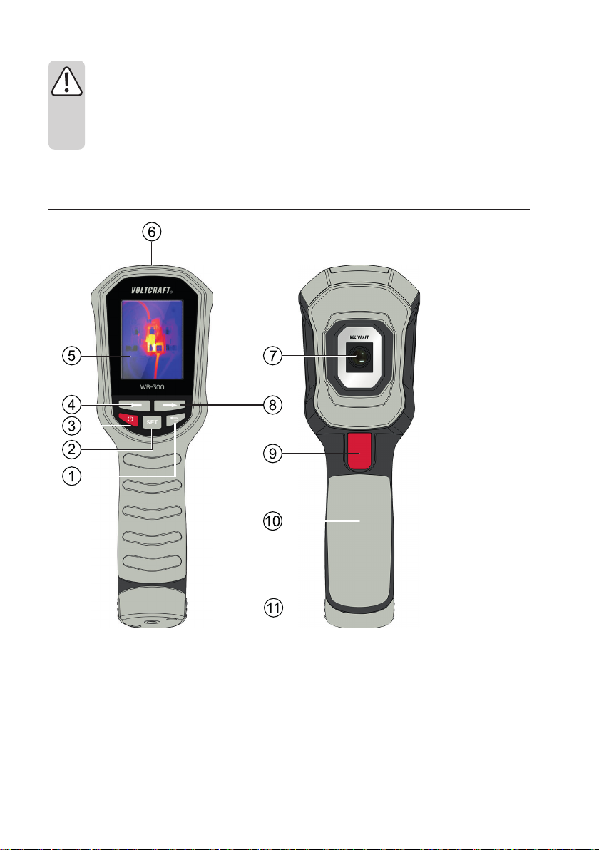
7. Operating elements
1 “Back” button
2 “SET” button (setting)
3 On/Off button
4 “Left” button for menu and cursor
5 TFT colour display
6 Rubber cover with microSD card slot and micro USB
charging socket
7 IR camera lens
8 “Right” button for menu and cursor
9 Trigger button for image storage
10 Handle
11 Battery compartment with integrated tripod thread
(1/4” UNC 20)
7

8. Product description
The thermal imaging camera has a graphic TFT colour display. This display can be used for all necessary displays
and to implement all settings.
The main menu, which can be called up via a multi-function button, allows you to set the operating parameters. The
arrow buttons allow easy navigation in the menu.
The camera provides a visual representation of heat distribution in objects and on surfaces. Temperature distribution
is displayed with false colour photography. Three different colour palettes can be set to ensure the best possible
contrast display.
The temperature in the centre of the image (spot area) as well as the maximum and minimum temperature values
are indicated by a marker. The thermal imaging function can be used for many areas of application with the extensive
setting options.
Thermal images can be stored on a microSD memory card.
9. Inserting and charging the battery
The lithium-ion battery is delivered pre-charged and must be fully charged before initial use.
Only use the charging cable included to charge the rechargeable Li-ion battery. A different charging cable might be
undersized. This creates a re hazard.
The camera becomes hot during charging. Place the camera on a at, robust and heat-resistant surface.
Inserting the rechargeable battery into the camera and removing the rechargeable battery
• Place the measuring instrument sideways on a soft surface.
• Use a suitable Phillips-head screwdriver to unscrew the two screws on the battery compartment (11).
• Pull the battery compartment out of the camera handle.
• Insert the rechargeable battery into the measuring instrument with the plus (+) contact rst. The polarity is indicated
on the battery compartment
• Close the battery compartment in reverse order and screw it back in carefully.
cover.
Charging the battery pack
The battery must be charged upon initial operation or when the battery status indicator lights up red.
1 Open the rubber cover (6) on the top of the device.
2 Insert the micro USB plug on the charging cable into the micro USB charging socket on the camera.
3 Insert the USB plug on the charging cable into a USB charging socket on a computer or on a suitable USB charger.
4 The charging indicator will appear on the display to indicate the charging process.
5 When the battery symbol turns green, the charging process is completed.
6 Disconnect the charging cable and close the rubber cover carefully.
7 The measuring instrument is ready for operation.
8

10. Inserting and removing the memory card
The measuring instrument allows thermal images to be stored on a removable microSD memory card. This makes it
is possible to easily exchange data and further process image data on a computer.
microSD cards of up to 16 GB can be used.
To insert/replace the memory card, proceed as follows::
• Open the rubber cover (6) on the top of the device.
• The memory card slot is on the left. The symbol for the correct position of the memory
card is indicated. The memory card contacts must face the display.
• Gently push the memory card into the slot until it clicks into place. Ensure that the memory card engages in the slot. This is the only way of ensuring reliable storage.
• To remove the memory card, briey press on the card until it is unlocked and pushed up
slightly. You can then easily remove the card.
• Carefully close the rubber cover to ensure protection against moisture and dust.
If the memory card is not recognised when triggering memory with the red trigger button (9) for
image storage (card symbol with a red X on the display), check the memory capacity, the correct fit
or the correct data formatting (FAT32) of the memory card.
11. Setup
a) Turning the camera on and off
• Use the red on/off button (3) to turn the camera on and off.
• To turn the camera on, press and hold down the red on/off button on the keypad below the display for approx. two
seconds.
• The camera will turn on and display the “VOLTCRAFT” start screen for approx. four seconds. The image sensor will
be calibrated at the same time. This is indicated by a quiet clicking sound.
• Once the automatic calibration is completed, the currently captured thermal image is displayed.
• To turn the camera off, press and hold down the red on/off button on the keypad below the display for approx. two
seconds. The device turns off.
9

b) Control keypad
Different buttons are used to control and set the measuring instrument. The buttons have the following functions:
On/off button (3)
To turn the device on or off, press and hold down the button for approx. two seconds.
Automatic power-off can be set in the menu. The device will then automatically power
off after a preset time.
SET button (2)
The SET button opens the settings menu. In the settings menu, this button is used as
a selection button (Enter) when pressed briey.
Use the “Back” button to exit the settings menu.
Back button (1)
The “Back” button returns to the previous menu item. In the main menu, pressing this
button will exit the menu.
Cursor buttons (4/8)
Use the “left arrow” and “right arrow” cursor buttons to select the menu items and
parameters in the settings menu.
10

c) Display elements and symbols
The following symbols and information are shown on the display.
1 symbol is used to turn on the temperature alarm function.
“High” option is used to turn on high temperature alarm.
“Low” option is used to turn on low temperature alarm.
2 “Crosshairs” symbol for setting the temperature markers in the thermal image
3 Symbol for setting the colour palettes
4 “Image gallery” symbol for displaying the stored thermal images
5 Symbol for system settings
6 Emission level display
7 Date display
8 Time display
9 Temperature scale with the lowest measured value and overlying colour distribution
10 Marker for spot measuring point (value display no. 14)
11 “L” marker for minimum value
12 “H” marker for maximum value
13 Temperature scale with the highest measured value
14 Temperature display of the spot measurement in the centre of the image
15 Battery status indicator
11

d) System settings
The measuring instrument allows the system data relevant to the user to be set via a menu. Such data includes the
menu language, units of measurement, time and date, etc.
These system settings must be made in advance so measurements can be stored with a time stamp, etc.
• When the measuring instrument is on, press the SET button to return to the main menu.
• Press the “left arrow” (4) or “right arrow” (8) cursor buttons until the gear symbol is marked.
• Press the “SET” button to conrm the selection. The system settings menu will now open.
Due to the size of the display, only seven menu areas can be displayed. Use the cursor buttons (4/8) to move the
menu. The selected menu item will be highlighted in colour.
• To activate the menu item, press the “SET” button.
• Use the cursor buttons to select the respective parameters and press the “SET” button to conrm the selection.
• Use the “Back” button (1) to exit the menu item.
The system menu has the following setting functions:
Original National
language
Language Sprache Menu language selection
Date/Time Datum/Zeit Date and time setting
Emissivity Emissivität Emission level setting
Auto OFF Auto Aus Automatic power-off setting
Brightness Helligkeit Setting the display brightness
Temp Unit Temp Einheit Temperature unit setting
Temperature Alarm Temperatur Alarm Setting for temperature alarms when exceeding or falling below
About Systeminfo S
Format SD Format SD Formatting the memory card
Recovery Wiederherstellen Restore to factory settings
Auto Save Auto Speichern Setting whether images should be saved without a new query after
Temp Bar Farbbalken Display of colour distribution as a bar
Meaning
certain levels
ystem data display (model, memory card size, software version, etc.)
pressing the memory button.
12

Setting the menu language
• On initial operation, set the menu language to your national language.
• Turn on the measuring instrument and press the SET button.
• Use the cursor buttons to select the gear symbol and press the “SET” button to conrm the selection.
• Use the cursor buttons to select the menu item “Language” and press the “SET” button to conrm the selection.
• Use the cursor buttons to select “German” or “English”. Press the “SET” button to conrm the selection.
• Use the “Back” button to return to the previous menu items.
Menu structure
The following table provides an overview of the menu structure and the setting options after switching the menu
language to your national language:
Language German
Date/Time DD/MM/YYYY
English
MM/DD/YYYY
YYYY/MM/DD
DD/MM/YYYY
MM/DD/YYYY
YYYY/MM/DD
24H
12H
07/02/2019 22:45 Use the “Back” button to
advance to individual date and
time elds.
Emissivity O Custom 0.01 – 0.99
O Sand 0.90
Textiles 0.90
Aluminium (plain) 0.04
Concrete 0.94
Rubber (black) 0.94
Wood 0.94
Varnish (matt) 0.97
Skin (human) 0.98
Plastic 0.94
Paper 0.97
Firstly, select the main eld for setting with the “SET” button. The yellow dot shows the active eld. Then
press the “SET” button again to select the parameters. The adjustable parameters are displayed in yellow.
13

Auto off 1 min
5 mins
10 mins
Off
Brightness Low
Middle
High
Temp Unit °F
ºC
Temperature Alarm High -10 to +400 °C
Low -10 to +400 °C
About Model: WB-300
Capacity: xxxx
Available: xxxx
Version: xxx
Product ID: XXXXXXXXX
Recovery No
Yes
Format SD No
Yes
The duration of the formatting process depends on the memory card size. “Formatting...” will be displayed
during formatting. Please wait until this message disappears. Do not turn off the device ahead of time,
otherwise the memory card may be damaged.
Auto Save Off
On
Temp Bar Off
On
14

e) High/Low Temperature Alarm
To set a high/low temperature alarm, proceed as follows:
• Press the “SET” button to open the main menu.
• Use the cursor buttons to select the gear symbol .
• Press the “SET” button to conrm the gear symbol .
• Press left/right button to select the “Temp Alarm” option.
• Press the “SET” button to enter the “Temp Alarm” submenu.
• Press left/right button to select “High” or “Low”.
- Press the “SET” button to enter the “High” or “Low” setting.
- Use the cursor buttons to adjust the temperature.
- Press the “SET” button to save the new temperature value.
• Press the “Back” button to return to the main menu.
• Press the “Back” button again to return to the image display page.
To turn a high/low temperature alarm on, proceed as follows:
• Press the “SET” button to open the settings menu.
• Use the cursor buttons to select the symbol.
• Press the “SET button to enter the submenu.
• Use the cursor buttons to select the desired option.
• Press the “SET button to conrm the option.
• An orange dot indicates the corresponding alarm function is turned on.
• Press the “Back” button to exit and return to the main menu.
• Press the “Back” button to return to the image display page.
NOTE
There are two modes for the high/low temperature alarm function:
• High 400 °C
• Low -10 °C.
The temperature alarm ranges correspond to the temperature alarm setting menu.
15

f) Setting the temperature markers
By default, the spot temperature for the thermal image is displayed on the upper left corner of the screen. You can use various settings to mark the actual
measuring point. The middle measuring point can be displayed, in which the
temperature measurement takes place. Similarly, two markers for the lowest
and highest measuring points can be shown in the image.
Centre
The middle spot measuring point is marked as crosshairs. The temperature
is measured here, with the temperature value displayed on the upper left
corner of the screen. The spot measuring point is xed in the centre and
cannot be changed.
High/Low
The lowest measuring point is marked with a blue frame and the letter “L” in
the image.
The highest measuring point is marked with a red frame and the letter “H” in the image.
These two markers are dynamic and automatically change their position depending on the heat distribution in the
image.
To display the temperature markers, proceed as follows:
• Press the “SET” button to open the settings menu.
• Use the cursor buttons to select the “crosshairs” symbol and press the “SET” button to conrm the selection.
• Use the cursor buttons to select the corresponding parameters. The selected range will be highlighted in colour.
• Press the “SET” button to conrm the selection. The setting is marked with a yellow dot. Both parameters can also
be enabled.
• To exit the menu, press the “Back” button.
16

g) Setting the colour palette
Set the colour palette to choose the optimal display contrast for your measurement application. There are three colour palettes.
Iron palette
Typical colour palette for thermal image applications. The cool spots are displayed dark and turn from red to white for the hot spots.
Rainbow palette
The cool spots are displayed dark and turn from bright colours to white for the
hot spots in rainbow mode.
Grey palette
The cool spots are displayed in black and become brighter in the grey range
for the hot spots. Here, the cold to hot contrast ratio is the greatest.
Grey-red palette (hot)
Highlights the high temperature part, which is displayed as red or orange
Blue-grey palette (cold)
Highlights the low temperature part, which is displayed as blue.
To set the colour palette, proceed as follows:
• Press the “SET” button to open the settings menu.
• Use the cursor buttons to select the “colour palette” symbol and press the “SET” button to conrm the selection.
• Use the cursor buttons to select the corresponding parameters. The selected range will be highlighted.
• Press the “SET” button to conrm the selection. The setting is marked with a yellow dot.
• To exit the menu, press the “Back” button.
17

h) Image gallery
The saved images can be viewed directly on the camera. In addition, the thermal image parameters can be displayed
and unnecessary images can be deleted directly.
To view/delete the saved images, proceed as follows:
• Press the “SET” button to open the settings menu.
• Use the cursor buttons to select the “image gallery” symbol and press the “SET” button to conrm the selection.
• Use the cursor buttons to select the corresponding image and press the “SET” button to conrm the selection.
• Use the “i” symbol to display other data stored in the image.
• Use the dustbin symbol to delete the image. Use the cursor buttons to select the function and press the “SET” but-
ton to conrm the selection. Use the “SET” button to re-conrm your entry or use “No” to cancel.
• To exit the menu, press the “Back” button.
18

12. Taking measurements
In order to obtain precise measured values, the measuring instrument must be adjusted to the
ambient temperature. Allow the device to adjust to the ambient temperature after relocation.
Lengthy IR measurements of high temperatures at a small measuring distance cause self-heating
of the measuring instrument and thus an inaccurate measurement. In order to obtain precise
measured values, remember the following rule of thumb: The higher the temperature, the greater
the measuring distance and the shorter the measuring time.
Shiny surfaces affect the IR measurement results. To compensate, the shiny part of the surface can be
covered with adhesive tape or matt black paint. In this case, the emission level must always be adjusted
to the surface to be measured. The device cannot measure through transparent surfaces such as glass.
Instead, it measures the surface temperature of the glass.
a) Function
Infrared thermal imaging cameras measure the surface temperature of an object and indicate these temperature
distributions with false colour photography.
The IR detector records the heat radiation emitted, reected and transmitted through the object and converts this
information into a temperature value. The measuring instrument has a built-in detector with a resolution of 160 x 120
pixels. This means that the detector records 160 x 120 temperature points in one measurement.
The emission level is a value used to describe the energy radiation characteristics of a material. The higher this value,
the more radiation a material can emit.
Many organic materials and surfaces have an emission level of approx. 0.95. Metallic surfaces or shiny materials
have a lower emission level. This will cause an inaccurate reading. For this reason, a matt black layer of paint or
matt adhesive tape should be applied to metallic shiny surfaces or the emission level should be preset accordingly.
The IR lens (7) is at the front of the device. Clean the lens with a soft cloth for lenses (eyeglass cleaning cloth, etc.).
This prevents damage or soiling of the lens.
The IR camera lens has a 56° x 42° eld of view (FOV).
b) Carrying out IR measurement
• Turn on the camera. It takes approx. four seconds for the detector to be calibrated.
The calibration process is identiable by a short click sound. Calibration is also carried out regularly during
measurement. This helps the detector to retain its accuracy over longer measuring phases. During the
calibration procedure, the detector is covered internally and no temperature updates are carried out (frozen
image).
• As soon as the initialisation is completed, the thermal image is displayed with false colours. The measurement is
carried out continuously with an update rate of <9 Hz.
• The colour palettes, the temperature unit and the emission level can be set in the settings menu as desired. Preset
values are colour palette 1, degrees Celsius and emission level 0.95.
• The display shows the measured value for the centre of the image. Min and Max markers can automatically measure and mark temperature peaks depending on the setting.
• Turn off the measuring instrument once the measurement is completed.
19

c) Saving the screen content
IR thermal images or screenshots of measured values can be stored on the removable microSD memory card. The
images are saved in bitmap format (.bmp) and can be reused by all graphics and table editing programs. This allows
for logging of measurement series.
• Switch the measuring instrument on.
• Make sure a memory card is inserted.
• Perform a measurement. Use the red trigger button (9) to capture the desired image.
• The display now shows the “Save” symbol in the toolbar. Press the corresponding cursor button. Use “X” to cancel
the saving and “tick” to save the image.
• The measuring instrument will create a separate folder named “Images” in the memory card. The images can be
stored with a time stamp in the le name as follows:
img Datum_Fortlaufende Zahl.bmp
Example:
img20190208_0000.bmp
img20190208_0001.bmp
The data on the memory card can be read by the measuring instrument or a computer via an optional memory card
terminal.
d) Automatic shut-off feature
The camera enables automatic power-off after a preset time. This function protects the rechargeable battery and
extends the operating time. The automatic shut-off function can be disabled to allow longer measurements to be
carried out.
The automatic power-off can be set in the system settings under the “Auto Off” menu item.
20

13. Cleaning and maintenance
a) General information
To ensure the accuracy of the thermal imaging camera over a long period of time, it should be calibrated at least
once a year.
The measuring instrument is absolutely maintenance-free except for occasional cleaning and battery replacement.
Regularly check the device for technical safety, for example, for damage to the casing or deformation,
etc.
b) Cleaning the casing
Always observe the following safety information before cleaning the device:
Do not use abrasive detergents, petrol, alcohol or other similar chemicals to clean the device. These may
To clean the device and the display, use a clean, lint-free, antistatic and slightly damp cleaning cloth. Allow the device
to dry completely before using it again.
c) Cleaning the lens
Remove loose particles with clean compressed air and wipe off remaining residue with a ne lens brush. Clean the
surface of the lens with a lens cloth or a soft, lint-free cloth.
The cloth can be moistened with water or a lens cleaning solution to remove ngerprints and other residue.
Do not use any acidic, alcoholic or other solvents or rough, linty cloth to clean the lens.
Avoid applying too much pressure when cleaning the lens.
corrode the surface of the measuring instrument. In addition, the vapours emitted by these substances are
explosive and harmful to your health. Do not use sharp-edged tools, screwdrivers or metal brushes to clean
the device.
21

14. Disposal
Electronic products are raw material and do not belong in the household waste. At the end of its service
life, dispose of the product according to the relevant statutory regulations. Remove the inserted battery cell
and dispose of it separately from the product.
Disposal of used batteries/rechargeable batteries!
You are required by law to return all used batteries. They must not be placed in household waste.
Contaminated batteries/rechargeable batteries are labelled with symbols to indicate that disposal in the do-
mestic waste is forbidden. The designations for the heavy metals involved are: Cd=cadmium, Hg=mercury,
Pb=lead (the marking can be seen on the battery, e.g., underneath the refuse bin symbol shown on the left).
Used batteries can be returned to local collection points, our stores or battery retailers.
That way you full your statutory obligations and contribute to the protection of the environment!
15. Troubleshooting
In purchasing this measuring device, you have acquired a product which has been designed to the state of
the art and is operationally re liable. However, problems and malfunctions may still occur. This section tells
you how to troubleshoot common issues:
Error Possible cause Solution
The camera does not work. Is the battery empty? Check the status. Charge the bat-
The measured value does not
change.
Repairs other than those described above should be performed only by an authorised specialist. If
you have questions about the measuring instrument, please contact our technical support team.
You are currently in the image
gallery mode.
tery, if necessary.
Press the “Back” button until you
are in the measuring mode.
22

16. Technical data
Measuring tolerances
These accuracy readings are valid for one year at a temperature of +23 °C (± 5 °C) and a relative humidity of less
than 75%, non-condensing.
The accuracy of measurements may be affected when the device is used in a high-frequency electromagnetic eld.
Measurement range .........................................-10 to +400 °C
Accuracy ...........................................................± 3.5% or ± 3.5 °C
Resolution .........................................................0.1 °C
IR resolution (bolometer matrix) .......................160 x 120 pixels (19200 pixels)
Detector pixel size ............................................12 µm
Thermal sensitivity (NETD) ...............................150 mK
Field of view (FOV) ...........................................56° x 42°
Refreshing rate .................................................<9 Hz
Focus ................................................................focus free (x-focus)
Minimum focus area .........................................25 cm
Spectral range ..................................................8 – 14 µm
Colour LC display .............................................6.1 cm (2.4”), 240 x 320 pixels
Colour palettes .................................................iron, rainbow, grey, grey-red (hot), blue-grey (cold)
Emission level ...................................................0.1 – 0.99 (0.95 preset)
Operating temperature .....................................-10 to +45 °C
Storage temperature .........................................-20 to +50 °C
Power supply ....................................................rechargeable Li-ion battery 3.7 V/DC, 2500 mAh, USB charging
Battery life .........................................................approx. 3 h
Interface ............................................................microSD slot (max. 16 GB)
Image storage format ........................................bmp
Protection type ..................................................IP54
Fall and impact protection ................................max. 2 m
Product dimensions (L x W x H) .......................78 x 72 x 213 mm
Weight ..............................................................approx. 354 g
23

This is a publication by Conrad Electronic SE, Klaus-Conrad-Str. 1, D-92240 Hirschau (www.conrad.com).
All rights including translation reserved. Reproduction by any method, e.g. photocopy, microlming, or the capture in
electronic data processing systems require the prior written approval by the editor. Reprinting, also in part, is prohibited.
This publication represent the technical status at the time of printing.
Copyright 2019 by Conrad Electronic SE.
2127008_V1_0819_02_dh_m_gb
 Loading...