

Page 1
Impressum
Dies ist eine Publikation der Conrad Electronic SE, Klaus-Conrad-Str. 1, D-92240 Hirschau (www.conrad.com).
Alle Rechte einschließlich Übersetzung vorbehalten. Reproduktionen jeder Art, z. B. Fotokopie, Mikroverlmung, oder die Erfassung in
elektronischen Datenverarbeitungsanlagen, bedürfen der schriftlichen Genehmigung des Herausgebers. Nachdruck, auch auszugsweise,
verboten. Die Publikation entspricht dem technischen Stand bei Drucklegung.
© Copyright 2016 by Conrad Electronic SE
Legal notice
This is a publication by Conrad Electronic SE, Klaus-Conrad-Str. 1, D-92240 Hirschau (www.conrad.com).
All rights including translation reserved. Reproduction by any method, e.g. photocopy, microlming, or the capture in electronic data
processing systems require the prior written approval by the editor. Reprinting, also in part, is prohibited. This publication represent the
technical status at the time of printing.
© Copyright 2016 by Conrad Electronic SE
Information légales
Ceci est une publication de Conrad Electronic SE, Klaus-Conrad-Str. 1, D-92240 Hirschau (www.conrad.com).
Tous droits réservés, y compris de traduction. Toute reproduction, quelle qu‘elle soit (p. ex. photocopie, microlm, saisie dans des
installations de traitement de données) nécessite une autorisation écrite de l‘éditeur. Il est interdit de le réimprimer, même par extraits.
Cette publication correspond au niveau technique du moment de la mise sous presse.
© Copyright 2016 by Conrad Electronic SE
Colofon
Dit is een publicatie van Conrad Electronic SE, Klaus-Conrad-Str. 1, D-92240 Hirschau (www.conrad.com).
Alle rechten, vertaling inbegrepen, voorbehouden. Reproducties van welke aard dan ook, bijvoorbeeld fotokopie, microverlming of de
registratie in elektronische gegevensverwerkingsapparatuur, vereisen de schriftelijke toestemming van de uitgever. Nadruk, ook van
uittreksels, verboden. De publicatie voldoet aan de technische stand bij het in druk bezorgen.
© Copyright 2016 by Conrad Electronic SE
V4_0816_02_JH
VC-890 OLED DIGITAL-MULTIMETER
BEDIENUNGSANLEITUNG
Seite 4 – 44
VC-890 OLED DIGITAL MULTIMETER
OPERATING INSTRUCTIONS
Page 45 – 85
VC-890 OLED MULTIMÈTRE NUMÉRIQUE
MODE D’EMPLOI
Page 86 – 126
VC-890 OLED DIGITALE MULTIMETER
GEBRUIKSAANWIJZING
Best.-Nr. / Item No. / N° de commande / Bestnr.:
124600
Pagina 127 – 167
Diese Bedienungsanleitung gehört zu diesem Produkt. Sie enthält wichtige Hinweise zur
Inbetriebnahme und Handhabung. Achten Sie hierauf, auch wenn Sie dieses Produkt an
Dritte weitergeben.
Heben Sie deshalb diese Bedienungsanleitung zum Nachlesen auf! Eine Auistung
der Inhalte nden Sie in dem Inhaltsverzeichnis mit Angabe der entsprechenden
Seitenzahlen auf Seite 4.
These Operating Instructions accompany this product. They contain important
information on setting up and using the device. You should refer to these instructions,
even if you are buying this product for someone else.
Please retain these Operating Instructions for future use! A list of the contents can be
found in the Table of contents, with the corresponding page number, on page 45.
Le présent mode d’emploi fait partie intégrante du produit. Il comporte des directives
importantes pour la mise en service et la manipulation de l’appareil. Tenir compte de
ces remarques, même en cas de transfert du produit à un tiers.
Conserver ce mode d’emploi an de pouvoir le consulter à tout moment. La table des
matières avec indication des pages correspondantes se trouve à la page 86.
Deze gebruiksaanwijzing hoort bij dit product. Zij bevat belangrijke informatie over
de inbedrijfstelling en het gebruik. Let hierop, ook wanneer u dit product aan derden
overhandigt.
Bewaar daarom deze gebruiksaanwijzing om in voorkomende gevallen te kunnen
raadplegen. In de inhoudsopgave op pagina 127 vindt u een lijst met inhoudspunten
met vermelding van het bijbehorende.
Version 08/16
Page 2
INHALTSVERZEICHNIS
Seite
TRUE RMS MULTIMETER
d
c
b
a
1. Einführung ...................................................................................................................................... 5
2. Bestimmungsgemäße Verwendung ............................................................................................... 6
3. Bedienelemente ............................................................................................................................. 7
4. Zeichenerklärung ........................................................................................................................... 9
5. Sicherheitshinweise ..................................................................................................................... 10
6. Produktbeschreibung ................................................................................................................... 13
7. Lieferumfang ................................................................................................................................ 13
8. Display-Angaben und Symbole .................................................................................................... 14
9. Batterie ......................................................................................................................................... 15
10. Uhrzeit und Datum einstellen ....................................................................................................... 16
11. Messbetrieb ..................................................................................................................................17
12. RANGE-Funktion, manuelle Messbereichswahl .......................................................................... 25
13. REL-Funktion ............................................................................................................................... 26
14. Hold-Funktion ............................................................................................................................... 26
15. MAX. / MIN. / AVG.-Funktion ........................................................................................................ 26
16. Low Imp. 400 KΩ –Funktion ......................................................................................................... 27
17. Vergleichs-Modus (Comp-Mode) .................................................................................................27
18. Messwerte aufzeichnen und verwalten ........................................................................................ 29
19. Auto-Power-Off-Funktion..............................................................................................................32
20. Optische Schnittstelle ...................................................................................................................32
21. Installation der Software ...............................................................................................................33
22. Displayhelligkeit ........................................................................................................................... 33
23. Wartung und Reinigung ................................................................................................................ 34
24. Entsorgung ................................................................................................................................... 38
25. Behebung von Störungen ............................................................................................................ 38
26. Technische Daten ......................................................................................................................... 40
3 4
Page 3

1. EINFÜHRUNG
Sehr geehrte Kundin, sehr geehrter Kunde,
mit dem Kauf eines Voltcraft®-Produktes haben Sie eine sehr gute Entscheidung getroffen, für die
wir Ihnen danken.
Voltcraft® - Dieser Name steht auf dem Gebiet der Mess-, Lade- sowie Netztechnik für
überdurchschnittliche Qualitätsprodukte, die sich durch fachliche Kompetenz, außergewöhnliche
Leistungsfähigkeit und permanente Innovation auszeichnen.
Vom ambitionierten Hobby-Elektroniker bis hin zum professionellen Anwender haben Sie mit einem
Produkt der Voltcraft® - Markenfamilie selbst für die anspruchsvollsten Aufgaben immer die optimale
Lösung zur Hand. Und das Besondere: Die ausgereifte Technik und die zuverlässige Qualität unserer
Voltcraft® - Produkte bieten wir Ihnen mit einem fast unschlagbar günstigen Preis-/Leistungsverhältnis
an. Darum schaffen wir die Basis für eine lange, gute und auch erfolgreiche Zusammenarbeit.
Wir wünschen Ihnen nun viel Spaß mit Ihrem neuen Voltcraft® - Produkt!
Alle enthaltenen Firmennamen und Produktbezeichnungen sind Warenzeichen der jeweiligen
Inhaber. Alle Rechte vorbehalten.
Bei technischen Fragen wenden Sie sich bitte an:
Deutschland: www.conrad.de/kontakt
Österreich: www.conrad.at
www.business.conrad.at
Schweiz: www.conrad.ch
www.biz-conrad.ch
5
Page 4

2. BESTIMMUNGSGEMÄSSE VERWENDUNG
• Messen und Anzeigen der elektrischen Größen im Bereich der Überspannungskategorie CAT IV
bis max. 600 V bzw. CAT III bis max. 1000 V gegen Erdpotential, gemäß EN 61010-1 sowie alle
niedrigeren Kategorien.
• Messen von Gleich- und Wechselspannung bis max. 1000 V
• Messen von Gleich- und Wechselstrom bis max. 10 A
• Frequenzmessung bis 60 MHz
• Messen von Kapazitäten bis 60 mF
• Messen von Widerständen bis 60 MΩ
• Durchgangsprüfung (<10 Ω akustisch)
• Diodentest
• Temperaturmessung von -40 bis +1000 ºC
• Anzeige des Signalverhältnisses (Duty Cycle) in % (10 – 90 %)
• 1 kHz Tiefpasslter-Wechselspannungsmessung
• Vergleichswert-Messung
• Messwertespeicher und Datenlogger für 1000 Werte mit Zeitstempel
• Datenübertragung zum PC per optischer Schnittstelle
• Datums- und Uhrzeitanzeige
Die Messfunktionen werden über den Drehschalter angewählt. Die Messbereichswahl erfolgt in allen
Messfunktionen (außer Dioden- und Durchgangstest) automatisch. Eine manuelle Einstellung ist
jederzeit möglich.
Beim VC890 werden sowohl im Gleich-, als auch Wechselspannungs- und Strommessbereich EchtEffektiv-Messwerte (True RMS) angezeigt.
Die Polarität wird bei negativem Messwert automatisch mit Vorzeichen (-) dargestellt.
Die beiden Strom-Messeingänge sind mit keramischen Hochleistungssicherungen gegen Überlast
abgesichert.
Die Spannung im Strom-Messkreis darf 1000 V in CAT lll bzw. 600 V in CAT IV nicht überschreiten.
Eine Niedrig-Impedanz-Funktion (Low Imp) ermöglicht die Messung mit reduziertem Innenwiderstand.
Diese unterdrückt Phantomspannungen, die in hochohmigen Messungen auftreten können. Die
Messung mit reduzierter Impedanz ist nur in Messkreisen bis max. 1000 V und nur für max. 3 s
zulässig. Bei Betätigung der Low Imp-Taste ertönt ein Signalton und es erfolgt eine Warnanzeige
im Display.
Das Multimeter wird mit einer handelsüblichen, 9V-Alkali- oder Lithium-Blockbatterie betrieben. Der
Betrieb ist nur mit dem angegebenen Batterietyp zulässig. Eine automatische Abschaltung verhindert
die vorzeitige Entleerung der Batterie, wenn das Gerät eine Zeit lang nicht benutzt wird (Einstellungen:
5 Min., 15 Min., 30Min. oder AUS; siehe Kapitel „19. Auto-Power-Off-Funktion“).
6
Page 5
Während der Datenübertragung zum PC per optischer Schnittstelle ist die Auto-Power-Off-Funktion
abgeschaltet.
Das Multimeter darf im geöffneten Zustand, mit geöffnetem Batteriefach oder fehlendem
Batteriefachdeckel nicht betrieben werden. Die Schutzvorrichtung lässt kein Öffnen des Batterie- und
Sicherungsdeckels zu, wenn Messleitungen in den Messbuchsen stecken. Ebenso verhindert diese
das Einstecken von Messleitungen bei geöffnetem Batterie- und Sicherungsdeckel.
Messungen in Feuchträumen bzw. unter widrigen Umgebungsbedingungen sind nicht zulässig.
Widrige Umgebungsbedingungen sind: Nässe oder hohe Luftfeuchtigkeit, Staub und brennbare Gase,
Dämpfe oder Lösungsmittel sowie Gewitter bzw. Gewitterbedingungen wie starke elektrostatische
Felder usw.
Verwenden Sie zum Messen nur Messleitungen bzw. Messzubehör, welche auf die Spezikationen
des Multimeters abgestimmt sind.
Aus Sicherheits- und Zulassungsgründen (CE) ist das eigenmächtige Umbauen und/oder Verändern
des Produktes nicht gestattet. Eine andere Verwendung als oben beschrieben ist nicht erlaubt
und kann zur Beschädigung des Produkts führen. Darüber hinaus ist dies mit Gefahren, wie z. B.
Kurzschluss, Brand, Stromschlag usw. verbunden. Lesen Sie die Bedienungsanleitung genau durch
und bewahren Sie diese für späteres Nachschlagen auf.
Befolgen Sie alle Sicherheitshinweise und Informationen in dieser Anleitung.
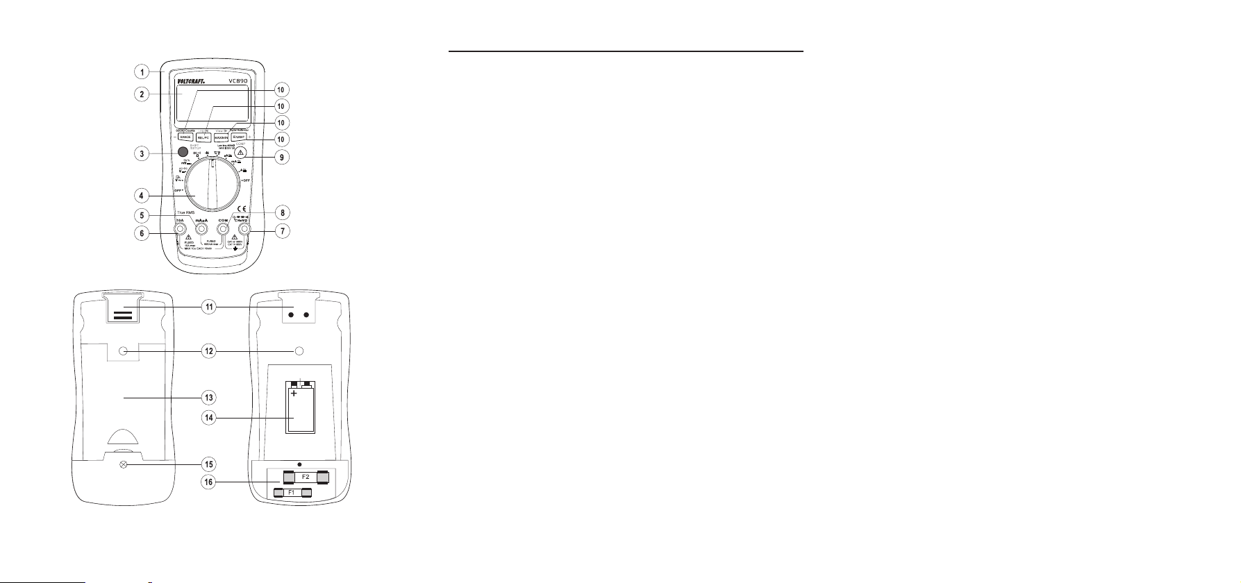
3. BEDIENELEMENTE
Siehe Ausklappseite.
1 Gummischutzrahmen
2 Display
3 SHIFT/SETUP-Taste
Umschaltung der Messfunktion (rote Symbole am Drehschalter) /
Funktionsumschaltung der Tasten (blaue Tastenbeschriftung)
4 Drehschalter zur Messfunktionswahl
5 mAμA-Messbuchse
6 10 A-Messbuchse
7 °CHzVΩ-Messbuchse (bei gleich großen „Plus“)
8 COM-Messbuchse (Bezugspotential, „Minus“)
-Taste
9
Low Imp. 400 kΩ-Taste zur Impedanzumschaltung
7
Page 6

10 Funktionstasten:
a H/LIGHT (+/COMP)-Taste:
„H“ = Hold-Funktion zum Einfrieren der Messanzeige
„LIGHT“ = Displayhelligkeit einstellen
„+“ = Wert erhöhen
„COMP“ = Vergleichsmodus
b MAX/MIN (View/►)-Taste:
„MAX/MIN“ = Zum Aufzeichnen und Anzeigen der Max.- und Min.-Werte
„View“ = gespeicherte Werte ansehen
„►“ = Navigation im SETUP-Menü
c REL/PC (Log/◄)-Taste:
„REL“ = Bezugswertmessung
„PC“ = Datenübertragung zum PC per optischer Schnittstelle
„Log“ = Werte speichern
„◄“ = Navigation im SETUP-Menü
d RANGE (-) Taste:
„RANGE“ = Manuelle Messbereichsumschaltung
„-“ = Wert verringern
11 Optisch isolierte Schnittstelle
12 Stativ-Anschlussgewinde
13 Klappbarer Aufstellbügel
14 Batteriefach
15 Schraube für Batterie- und Sicherungsfach
16 Sicherungsfach
8
Page 7
4. ZEICHENERKLÄRUNG
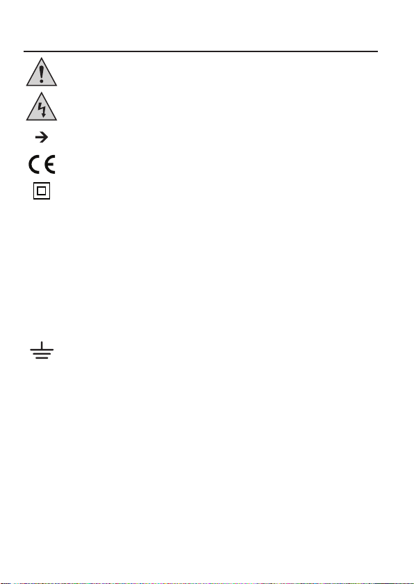
Ein Ausrufezeichen in einem Dreieck zeigt wichtige Anweisungen in dieser Anleitung, die
unbedingt befolgt werden müssen.
Ein Blitzsymbol im Dreieck warnt vor einem elektrischen Schlag oder der Beeinträchtigung
der elektrischen Sicherheit des Geräts.
Das „Pfeil“-Symbol ist zu nden, wenn Ihnen besondere Tipps und Hinweise zur
Bedienung gegeben werden sollen.
Dieses Gerät ist CE-konform und erfüllt die erforderlichen europäischen Richtlinien.
Schutzklasse 2 (doppelte oder verstärkte Isolierung)
Überspannungskategorie II für Messungen an elektrischen und elektronischen Geräten,
welche über einen Netzstecker mit Spannung versorgt werden. Diese Kategorie
CAT II
umfasst auch alle kleineren Kategorien (z.B. CAT I zur Messung von Signal- und
Steuerspannungen).
Überspannungskategorie III für Messungen in der Gebäudeinstallation (z.B. Steckdosen
CAT III
oder Unterverteilungen). Diese Kategorie umfasst auch alle kleineren Kategorien (z.B.
CAT II zur Messung an Elektrogeräten).
Überspannungskategorie IV für Messungen an der Quelle der Niederspannungsinstallation
CAT IV
(z.B. Hauptverteilung, Haus-Übergabepunkte der Energieversorger etc.). Diese Kategorie
umfasst auch alle kleineren Kategorien.
Erdpotential
9
Page 8

5. SICHERHEITSHINWEISE
Lesen Sie sich die Bedienungsanleitung aufmerksam durch und beachten Sie
insbesondere die Sicherheitshinweise. Falls Sie die Sicherheitshinweise und die
Angaben zur sachgemäßen Handhabung in dieser Bedienungsanleitung nicht
befolgen, übernehmen wir für dadurch resultierende Personen-/Sachschäden keine
Haftung. Außerdem erlischt in solchen Fällen die Gewährleistung/Garantie.
a) Personen / Produkt
• Das Produkt ist kein Spielzeug. Halten Sie es von Kindern und Haustieren fern.
• Lassen Sie das Verpackungsmaterial nicht achtlos liegen. Dieses könnte für Kinder zu
einem gefährlichen Spielzeug werden.
• Schützen Sie das Produkt vor extremen Temperaturen, direktem Sonnenlicht, starken
Erschütterungen, hoher Feuchtigkeit, Nässe, brennbaren Gasen, Dämpfen und
Lösungsmitteln.
• Setzen Sie das Produkt keiner mechanischen Beanspruchung aus.
• Wenn kein sicherer Betrieb mehr möglich ist, nehmen Sie das Produkt außer Betrieb
und schützen Sie es vor unbeabsichtigter Verwendung. Der sichere Betrieb ist nicht
mehr gewährleistet, wenn das Produkt:
- sichtbare Schäden aufweist,
- nicht mehr ordnungsgemäß funktioniert,
- über einen längeren Zeitraum unter ungünstigen Umgebungsbedingungen gelagert
wurde oder
- erheblichen Transportbelastungen ausgesetzt wurde.
• Gehen Sie vorsichtig mit dem Produkt um. Durch Stöße, Schläge oder dem Fall aus
bereits geringer Höhe wird es beschädigt.
• Beachten Sie auch die Sicherheitshinweise und Bedienungsanleitungen der übrigen
Geräte, an die das Produkt angeschlossen wird.
• Aus Sicherheits- und Zulassungsgründen (CE) ist das eigenmächtige Umbauen und/
oder Verändern des Geräts nicht gestattet.
• Wenden Sie sich an eine Fachkraft, wenn Sie Zweifel über die Arbeitsweise, die
Sicherheit oder den Anschluss des Geräts haben.
• In gewerblichen Einrichtungen sind die Unfallverhütungsvorschriften des Verbandes
der gewerblichen Berufsgenossenschaften für elektrische Anlagen und Betriebsmittel
zu beachten.
• In Schulen und Ausbildungseinrichtungen, Hobby- und Selbsthilfewerkstätten ist der
Umgang mit Messgeräten durch geschultes Personal verantwortlich zu überwachen.
10
Page 9

• Stellen Sie vor jeder Spannungsmessung sicher, dass sich das Messgerät nicht im
Strommessbereich bendet.
• Die Spannung zwischen den Anschlusspunkten des Messgeräts und Erdpotential darf
1000 V DC/AC in CAT III bzw. 600 V in CAT IV nicht überschreiten.
• Vor jedem Wechsel des Messbereiches sind die Messspitzen vom Messobjekt zu
entfernen.
• Seien Sie besonders Vorsichtig beim Umgang mit Spannungen >25 V Wechsel- (AC)
bzw. >35 V Gleichspannung (DC)! Bereits bei diesen Spannungen können Sie bei
Berührung elektrischer Leiter einen lebensgefährlichen elektrischen Schlag erhalten.
• Überprüfen Sie vor jeder Messung Ihr Messgerät und deren Messleitungen auf
Beschädigung(en).
• Führen Sie auf keinen Fall Messungen durch, wenn die schützende Isolierung
beschädigt (eingerissen, abgerissen usw.) ist.
• Um einen elektrischen Schlag zu vermeiden, achten Sie darauf, dass Sie die zu
messenden Anschlüsse/Messpunkte während der Messung nicht, auch nicht indirekt,
berühren.
• Über die fühlbaren Griffbereichsmarkierungen an den Messspitzen darf während des
Messens nicht gegriffen werden.
• Verwenden Sie das Multimeter nicht kurz vor, während oder kurz nach einem Gewitter
(Blitzschlag! / energiereiche Überspannungen!). Achten Sie darauf, dass ihre Hände,
Schuhe, Kleidung, der Boden, Schaltungen und Schaltungsteile usw. unbedingt
trocken sind.
• Vermeiden Sie den Betrieb in unmittelbarer Nähe von:
- starken magnetischen oder elektromagnetischen Feldern
- Sendeantennen oder HF-Generatoren.
Dadurch kann der Messwert verfälscht werden.
• Schalten Sie das Messgerät niemals gleich dann ein, wenn dieses von einem kalten
in einen warmen Raum gebracht wird. Das dabei entstandene Kondenswasser kann
unter Umständen Ihr Gerät zerstören.
• Lassen Sie das Gerät uneingeschaltet auf Zimmertemperatur kommen.
• Beachten Sie auch die Sicherheitshinweise in den einzelnen Kapiteln.
11
Page 10

b) Batterien / Akkus
• Achten Sie beim Einlegen der Batterien / Akkus auf die richtige Polung.
• Entfernen Sie die Batterien / Akkus, wenn Sie das Gerät längere Zeit nicht verwenden,
um Beschädigungen durch Auslaufen zu vermeiden. Auslaufende oder beschädigte
Batterien / Akkus können bei Hautkontakt Säureverätzungen hervorrufen. Beim
Umgang mit beschädigten Batterien / Akkus sollten Sie daher Schutzhandschuhe
tragen.
• Bewahren Sie Batterien / Akkus außerhalb der Reichweite von Kindern auf. Lassen
Sie Batterien / Akkus nicht frei herumliegen, da diese von Kindern oder Haustieren
verschluckt werden könnten.
• Nehmen Sie keine Batterien / Akkus auseinander, schließen Sie sie nicht kurz und
werfen Sie sie nicht ins Feuer. Versuchen Sie niemals, nicht auadbare Batterien
aufzuladen. Es besteht Explosionsgefahr!
c) Sonstiges
• Wenden Sie sich an eine Fachkraft, wenn Sie Zweifel über die Arbeitsweise, die
Sicherheit oder den Anschluss des Produktes haben.
• Lassen Sie Wartungs-, Anpassungs- und Reparaturarbeiten ausschließlich von einem
Fachmann bzw. einer Fachwerkstatt durchführen.
Sollten Sie sich über den korrekten Anschluss bzw. Betrieb nicht im Klaren sein oder sollten sich
Fragen ergeben, die nicht im Laufe der Bedienungsanleitung abgeklärt werden, so setzen Sie sich
bitte mit unserer technischen Auskunft oder einem anderen Fachmann in Verbindung.
12
Page 11
6. PRODUKTBESCHREIBUNG
Die Messwerte werden am Multimeter (im folgenden DMM genannt) in einer Digitalanzeige dargestellt.
Die Messwertanzeige des DMM umfasst 60000 Counts (Count = kleinster Anzeigewert).
Wenn das Gerät eine Zeit lang nicht bedient wird (Einstellungen: 5 Min., 15 Min., 30Min.), schaltet es
sich automatisch ab. Die Batterie wird geschont und ermöglicht eine längere Betriebszeit. Während
der Datenübertragung zum PC per optischer Schnittstelle ist diese Funktion abgeschaltet.
Das Messgerät ist sowohl im Hobby- als auch im professionellen Bereich bis CAT IV einsetzbar.
Zur besseren Ablesbarkeit kann das DMM mit dem rückseitigen Aufstellbügel ideal platziert werden.
Das Batterie- und Sicherungsfach kann nur geöffnet werden, wenn alle Messleitungen vom Messgerät
entfernt wurden. Bei geöffnetem Batterie- und Sicherungsfach ist es nicht möglich, die Messleitungen
in die Messbuchsen zu stecken. Dies erhöht die Sicherheit für den Benutzer.
Im Spannungs- und Strommessbereich erfolgt bei falsch angeschlossenen Messleitungen ein
Warnton mit Displayanzeigen. Schließen Sie die Messleitungen korrekt an, bevor Sie messen.
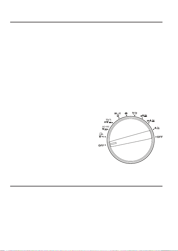
Drehschalter (4)
Die einzelnen Messfunktionen werden über einen
Drehschalter angewählt. Die automatische Bereichswahl
„AUTO“ ist in einigen Messfunktionen aktiv. Hierbei wird
immer der jeweils passende Messbereich eingestellt.
Beginnen Sie bei der Strommessung immer mit dem
größten Messbereich (10 A) und schalten Sie bei Bedarf
auf einen kleineren Messbereich um.
Das Multimeter ist in der Schalterposition „OFF“
ausgeschaltet. Schalten Sie das Messgerät bei
Nichtgebrauch immer aus. Die Abbildung 1 zeigt die
Anordnung der Messfunktionen.
Abb. 1
7. LIEFERUMFANG
• Multimeter mit Gummischutzrahmen
• 9 V Alkali-Blockbatterie
• 1 Satz Messleitungen
• 1 Satz Krokodilklemmen
• Draht-Temperaturfühler
• USB-Schnittstellenadapter
• Auswertesoftware „VOLTSOFT“
• Bedienungsanleitung
13
Page 12
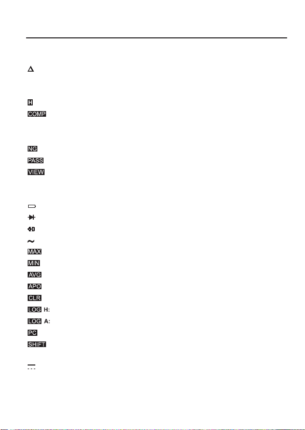
8. DISPLAY-ANGABEN UND SYMBOLE
Die Symbole und Angaben sind je nach Modell unterschiedlich vorhanden. Dies ist eine Aufstellung
aller möglichen Symbole und Angaben der Serie VC890.
Delta-Symbol für Relativwertmessung (=Referenzwertmessung)
AUTO steht für „Automatische Messbereichswahl“
TrueRMS Echt-Effektivwertmessung
Data-Hold-Funktion
Vergleichsmodus
> <
< >
OL Overload = Überlauf; der Messbereich wurde überschritten
OFF Schalterstellung „Aus“
AC Wechselspannung bzw. Wechselstrom
VOID Messwertespeicher enthält keine gespeicherten Messwerte
DC Gleichspannung bzw. Gleichstrom
mV Millivolt (=0,001 V)
V Volt (Einheit der elektrischen Spannung)
Grenzwertfestlegung, Messwert muss innerhalb zweier bestimmter Werte bleiben
Grenzwertfestlegung, Messwert muss außerhalb zweier bestimmter Werte bleiben
steht für „Vergleichstest nicht bestanden“
steht für „Vergleichstest bestanden“
Speicherstand laden
Symbol für Batteriewechsel (Batteriestand niedrig)
Symbol für den Diodentest
Symbol für den akustischen Durchgangsprüfer
Maximaler Messwert
Minimaler Messwert
Durchschnitts-Messwert
Automatische Abschaltung aktiviert
Messwertespeicher wird gelöscht
Manueller Messwertespeicher
Automatischer Messwertespeicher
Symbol für Datenübertragung (aktive Schnittstelle)
Funktionsumschaltung aktiviert (blaue Tastenbeschriftung)
14
Page 13
A Ampere (Einheit der elektrischen Stromstärke)
0 1 2 3 4 5 6
mA Milliampere (=0,001 A)
µA Mikroampere (=0,000.001 A)
Hz Hertz (Einheit der Frequenz)
kHz Kilohertz
MHz Megahertz
VA Voltampere (Einheit der elektrischen Scheinleistung)
% Prozentanzeige bei Duty Cycle-Messung
ºC Grad Celsius
ºF Grad Fahrenheit
Ω Ohm (Einheit des elektrischen Widerstands)
kΩ Kiloohm (=1.000 Ω)
MΩ Megaohm (=1.000.000 Ω)
nF Nanofarad (Einheit der elektrischen Kapazität = 0,000.000.001 F)
µF Mikrofarad (=0,000.001 F)
mF Millifarad (=0,001 F)
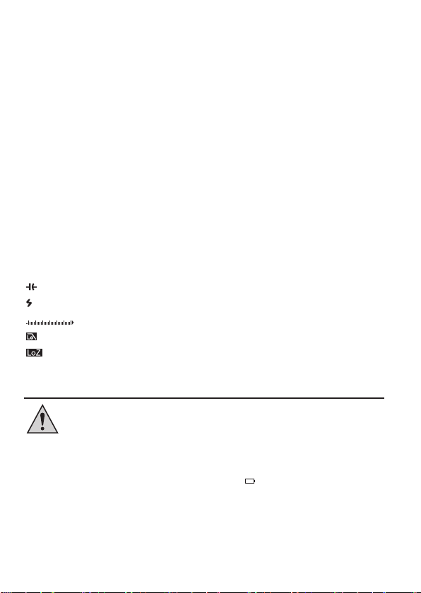
Symbol für den Kapazitätsmessbereich
Warnsymbol bei Spannungen > 30 V/AC und > 42 V/DC
Bargraph-Balkenanzeige (nur bei V, A, Ω)
Tiefpasslter für Wechselspannung
Low Imp-Funktion
9. BATTERIE
Bevor Sie mit dem Messgerät arbeiten können, muss erst die beiliegende Batterie
eingesetzt werden.
a) Einsetzen und Wechseln der Batterie
Zum Betrieb des Messgerätes wird eine 9 V-Alkali- oder Lithium-Blockbatterie benötigt. Bei
Erstinbetriebnahme oder wenn das Batterie-Zustandssymbol (leer) im Display erscheint, muss
eine neue, volle Batterie bzw. ein neuer, voller Akku desselben Typs eingesetzt werden. Beachten
Sie auch die Sicherheitshinweise zu Batterien / Akkus (Seite 12).
15
Page 14
Zum Einsetzen/Wechseln gehen Sie wie folgt vor:
1. Trennen Sie die angeschlossenen Messleitungen vom Messkreis und von Ihrem Messgerät.
Schalten Sie das DMM aus.
2. Öffnen Sie das Gehäuse wie im Kapitel „23. Wartung und Reinigung“ (Seite 35) beschrieben.
3. Ersetzen Sie die verbrauchte Batterie gegen eine neue desselben Typs. Setzen Sie die neue
Batterie polungsrichtig in das Batteriefach (14). Achten Sie auf die Polaritätsangaben im
Batteriefach.
4. Verschließen Sie das Gehäuse wieder sorgfältig.
b) Batterietyp einstellen
1. Stellen Sie im SETUP-Menü den verwendeten Batterietyp ein. Dies ermöglicht die korrekte
Anzeige des Batterieladestands.
2. Halten Sie bei eingeschaltetem Messgerät die SHIFT/SETUP-Taste (3) für ca. 2 s gedrückt. Auf
dem Display erscheint
3. Halten Sie die SHIFT/SETUP-Taste erneut für ca. 2 s gedrückt, um das SETUP-Menü zu öffnen.
4. Drücken Sie nun mehrmals auf die SHIFT/SETUP-Taste, bis der Menüpunkt „BATTERY TYPE“
ausgewählt ist. Ein Stern-Symbol * links neben dem Menüpunkt zeigt an, dass der Menüpunkt
ausgewählt ist.
5. Drücken Sie die Tasten REL/PC (Log/◄) oder MAX/MIN (View/►), um „LI-AKKU“ (Lithium-
Blockbatterie) oder „ALKALINE“ (Alkali-Blockbatterie) auszuwählen.
6. Halten Sie die SHIFT/SETUP-Taste für ca. 2 s gedrückt, um die Einstellung zu speichern und das
SETUP-Menü zu verlassen.
Eine passende Alkaline-Batterie erhalten Sie unter folgender Bestellnummer:
Best.-Nr. 652509
Eine passende Lithium-Batterie erhalten Sie unter folgender Bestellnummer:
Best.-Nr. 251292
. Sie benden sich nun im SHIFT-Modus.
10. UHRZEIT UND DATUM EINSTELLEN
1. Stellen Sie Uhrzeit und Datum im SETUP-Menü ein.
2. Halten Sie bei eingeschaltetem Messgerät die SHIFT/SETUP-Taste (3) für ca. 2 s gedrückt. Auf
dem Display erscheint
3. Halten Sie die SHIFT/SETUP-Taste erneut für ca. 2 s gedrückt, um das SETUP-Menü zu öffnen.
4. Der Menüpunkt „SET TIME“ (Uhrzeit einstellen) ist ausgewählt. Falls nicht, drücken Sie mehrmals
auf die SHIFT/SETUP-Taste, um den Menüpunkt „SET TIME“ auszuwählen. Ein Stern-Symbol *
links neben dem Menüpunkt zeigt an, dass der Menüpunkt „SET TIME“ ausgewählt ist.
16
. Sie benden sich nun im SHIFT-Modus.
Page 15
5. Mit Hilfe der Tasten REL/PC (Log/◄) und MAX/MIN (View/►) können Sie nun die Stunden,
Minuten und Sekunden anwählen. Stellen Sie die Werte mit den Tasten H/LIGHT (+/COMP) oder
RANGE (-) ein.
6. Drücken Sie nach erfolgter Einstellung die SHIFT/SETUP-Taste, um das Datum (Menüpunkt „SET
DATE“) einzustellen. Hier können Sie ebenfalls mit Hilfe der Tasten REL/PC (Log/◄) und MAX/
MIN (View/►) die einzelnen Stellen (Tag, Monat, Jahr) anwählen und deren Wert mit den Tasten
H/LIGHT (+/COMP) oder RANGE (-) verändern.
7. Halten Sie die SHIFT/SETUP-Taste für ca. 2 s gedrückt, um die Einstellungen zu speichern und
das SETUP-Menü zu verlassen. Sie verlassen dabei auch den SHIFT-Modus.
Wenn Datum und Uhrzeit nicht mehr korrekt angezeigt werden, muss die
Knopfbatterie ersetzt werden. Die Knopfbatterie hat eine Lebensdauer von ca. 3
bis 5 Jahren. Sie sichert die Stromversorgung für Datum und Uhrzeit, für den Fall,
dass die Batterie des DMM leer ist oder bei längerer Nichtbenutzung aus dem Gerät
entnommen wird. Das Wechseln der Knopfbatterie ist im Kapitel „23. Wartung und
Reinigung“ (Seite 37) beschrieben.
11. MESSBETRIEB
Überschreiten Sie auf keinen Fall die max. zulässigen Eingangsgrößen.
Berühren Sie keine Schaltungen oder Schaltungsteile, wenn darin höhere
Spannungen als 25 V ACrms oder 35 V DC anliegen können! Lebensgefahr!
Kontrollieren Sie vor Messbeginn die angeschlossenen Messleitungen
auf Beschädigungen wie z.B. Schnitte, Risse oder Quetschungen. Defekte
Messleitungen dürfen nicht mehr benutzt werden! Lebensgefahr!
Über die fühlbaren Griffbereichsmarkierungen an den Messspitzen darf während
des Messens nicht gegriffen werden.
Der Messbetrieb ist nur bei geschlossenem Batterie- und Sicherungsfach möglich.
Bei geöffnetem Fach sind alle Messbuchsen mechanisch gegen Einstecken
gesichert.
Es dürfen immer nur die zwei Messleitungen am Messgerät angeschlossen sein,
welche zum Messbetrieb benötigt werden. Entfernen Sie aus Sicherheitsgründen
alle nicht benötigten Messleitungen vom Messgerät.
Messungen in Stromkreisen >50 V/AC und >75 V/DC dürfen nur von Fachkräften
und eingewiesenen Personen durchgeführt werden, die mit den einschlägigen
Vorschriften und den daraus resultierenden Gefahren vertraut sind.
Sobald „OL“ (für Overload = Überlauf) im Display erscheint, haben Sie den Messbereich
überschritten.
17
Page 16
a) Multimeter einschalten
Das Multimeter wird über den Drehschalter (4) ein- und ausgeschaltet. Drehen Sie den Drehschalter
in die entsprechende Messfunktion. Zum Ausschalten bringen Sie den Drehschalter in Position „OFF“.
Schalten Sie das Messgerät bei Nichtgebrauch immer aus.
b) Spannungsmessung „V“
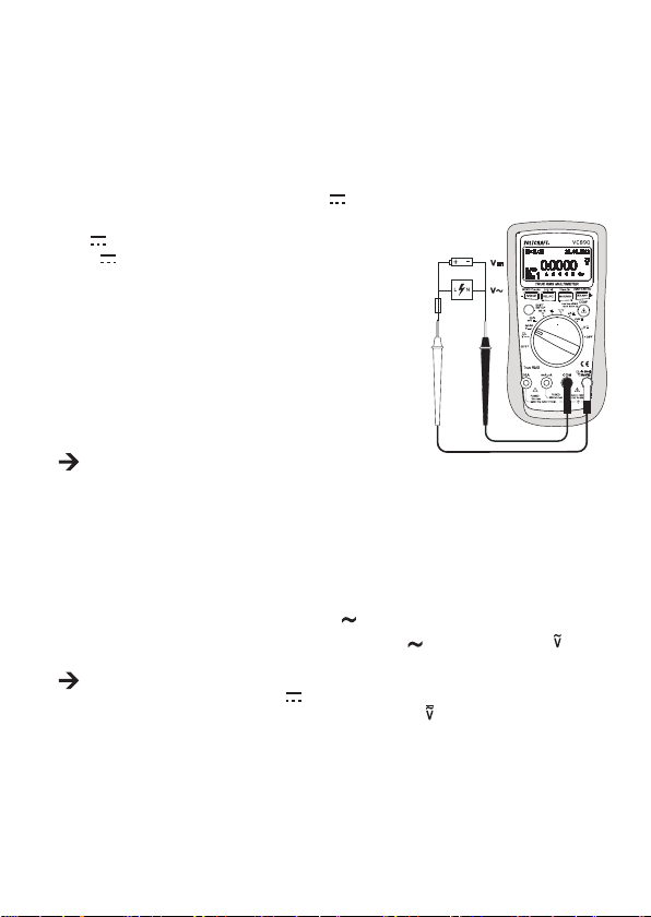
Zur Messung von Gleichspannungen „DC“ (V ) gehen Sie wie folgt vor:
1. Schalten Sie das DMM ein und wählen den Messbereich
“. Für kleine Spannungen bis max. 600 mV wählen Sie
„V
„mV “.
2. Stecken Sie die rote Messleitung in die °CHzVΩ-
Messbuchse (7), die schwarze Messleitung in die COMMessbuchse (8) (Abb. 2).
3. Verbinden Sie die beiden Messspitzen mit dem Messobjekt
(Batterie, Schaltung usw.). Die rote Messspitze entspricht
dem Pluspol, die schwarze Messspitze dem Minuspol.
4. Die jeweilige Polarität des Messwertes wird zusammen mit
dem augenblicklichen Messwert im Display angezeigt.
Sobald bei der Gleichspannung ein Minus „-“ vor dem
Messwert erscheint, ist die gemessene Spannung
negativ (oder die Messleitungen sind vertauscht).
Der Spannungsbereich „V DC/AC“ weist einen
Eingangswiderstand von >10 MΩ auf.
5. Entfernen Sie nach Messende die Messleitungen vom Messobjekt und schalten Sie das DMM aus.
Abb. 2
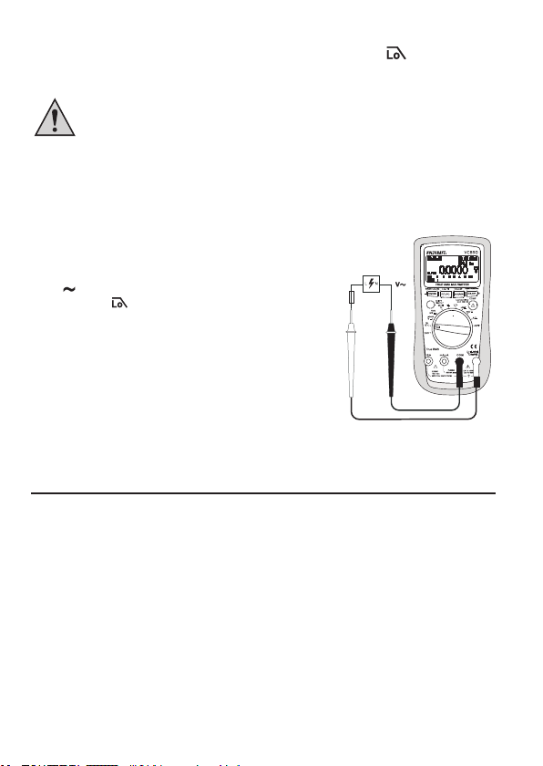
Zur Messung von Wechselspannungen „AC“ (V
1. Schalten Sie das DMM ein und wählen den Messbereich „V
Bei Bedarf können Sie die Messfunktion „AC+DC“ anwählen. Schalten Sie das DMM ein
und wählen den Messbereich „V “. Drücken Sie die SHIFT/SETUP-Taste (3), um zur
Messfunktion „AC+DC“ umzuschalten. Im Display erscheint „ “.
2. Stecken Sie die rote Messleitung in die °CHzVΩ-Messbuchse (7), die schwarze Messleitung in
die COM-Messbuchse (8).
3. Verbinden Sie die beiden Messspitzen mit dem Messobjekt (Generator, Schaltung usw.).
4. Der Messwert wird im Display angezeigt.
5. Entfernen Sie nach Messende die Messleitungen vom Messobjekt und schalten Sie das DMM aus.
18
) gehen Sie wie folgt vor:
“. Im Display erscheint „ “.
Page 17
c) Strommessung „A“
Überschreiten Sie auf keinen Fall die max. zulässigen Eingangsgrößen. Berühren
Sie keine Schaltungen oder Schaltungsteile, wenn darin höhere Spannungen als
25 V ACrms oder 35 V DC anliegen können! Lebensgefahr!
Die max. zulässige Spannung im Strommesskreis darf 1000 V in CAT III nicht
überschreiten. Messungen >5 A dürfen nur für max. 10 Sekunden und nur im
Intervall von 10 Minuten durchgeführt werden.
Beginnen Sie die Strommessung immer mit dem größten Messbereich und wechseln ggf. auf
einen kleineren Messbereich. Vor einem Messbereichswechsel immer die Schaltung stromlos
schalten. Alle Strommessbereiche sind abgesichert und somit gegen Überlastung geschützt.
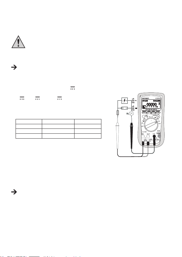
Zur Messung von Gleichströmen (A
1. Schalten Sie das DMM ein und wählen den Messbereich
“, „mA “ oder „μA “.
„A
) gehen Sie wie folgt vor:
2. In der Tabelle sind die unterschiedlichen Messfunktionen
und die möglichen Messbereiche ersichtlich. Wählen Sie den
Messbereich und die zugehörigen Messbuchsen.
Messfunktion Messbereich Messbuchsen
μA 0,01 μA - 6000 μA COM + mAμA
mA 0,001 mA - 600 mA COM + mAμA
10A 0,001 A - 10 A COM + 10A
3. Stecken Sie die rote Messleitung in die mAμA- oder
10A-Messbuchse (5, 6). Die schwarze Messleitung stecken
Sie in die COM-Messbuchse (8) (Abb. 3).
4. Verbinden Sie die beiden Messspitzen in Reihe mit dem
Abb. 3
Messobjekt (Batterie, Schaltung usw.); die jeweilige Polarität
des Messwertes wird zusammen mit dem augenblicklichen
Messwert im Display angezeigt.
Sobald bei Gleichstrommessung ein Minus „-“ vor dem Messwert erscheint, verläuft der Strom
entgegengesetzt (oder die Messleitungen sind vertauscht).
5. Entfernen Sie nach Messende die Messleitungen vom Messobjekt und schalten Sie das DMM aus.
19
Page 18
Zur Messung von Wechselströmen (A
1. Schalten Sie das DMM ein und wählen den Messbereich „A
2. Drücken Sie die SHIFT/SETUP-Taste (3), um in den AC-Messbereich umzuschalten. Im Display
erscheint „
3. Entfernen Sie nach Messende die Messleitungen vom Messobjekt und schalten Sie das DMM aus.
“, „ “ oder „ “. Eine erneute Betätigung schaltet wieder zurück.
Messen Sie im 10A-Bereich auf keinen Fall Ströme über 10 A bzw. im mA/μA-
Bereich Ströme über 600 mA, da sonst die Sicherungen auslösen.
) gehen Sie wie zuvor beschrieben vor.
“, „mA “ oder „μA “.
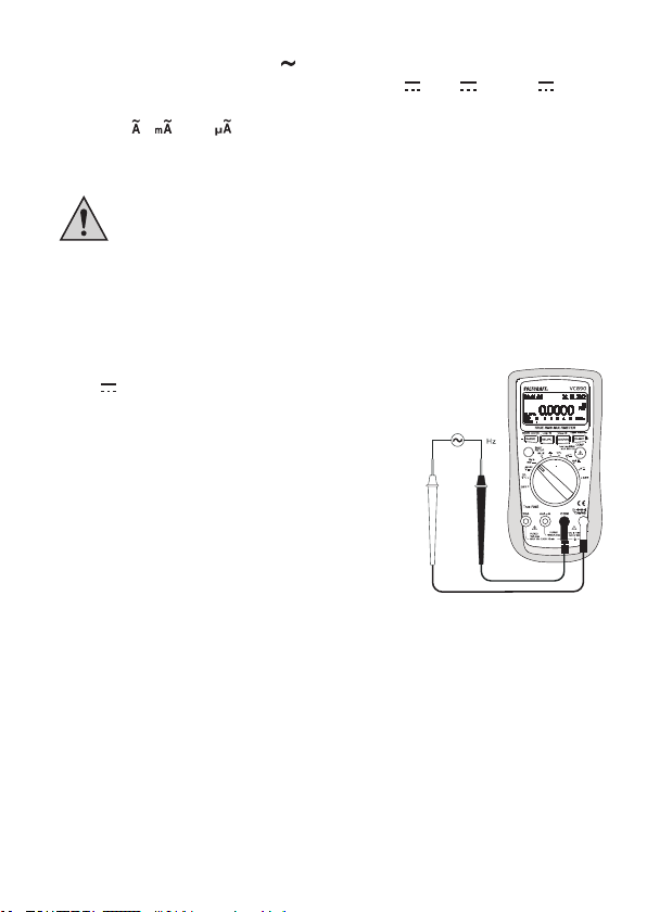
d) Frequenzmessung/Signalverhältnis in % (DutyCyle)
Das DMM kann die Frequenz einer Signalspannung von 10 Hz - 60 MHz messen und anzeigen.
Zur Messung von Frequenzen gehen Sie wie folgt vor:
1. Schalten Sie das DMM ein und wählen den Messbereich
„mV
Hz %“. Drücken Sie die SHIFT/SETUP-Taste (3) bis
im Display „Hz“ erscheint.
2. Stecken Sie die rote Messleitung in die °CHzVΩ-
Messbuchse (7), die schwarze Messleitung in die COMMessbuchse (8) (Abb. 4).
3. Verbinden Sie die beiden Messspitzen mit dem Messobjekt
(Signalgenerator, Schaltung usw.).
4. Die Frequenz wird mit der entsprechenden Einheit im Display
angezeigt.
5. Um das Signalverhältnis (Duty Cycle) zu messen, drücken Sie
erneut die SHIFT/SETUP-Taste bis „%“ im Display erscheint.
6. Entfernen Sie nach Messende die Messleitungen vom
Messobjekt und schalten Sie das DMM aus.
Abb. 4
20
Page 19
e) Widerstandsmessung
Vergewissern Sie sich, dass alle zu messenden Schaltungsteile, Schaltungen und
Bauelemente sowie andere Messobjekte unbedingt spannungslos und entladen
sind.
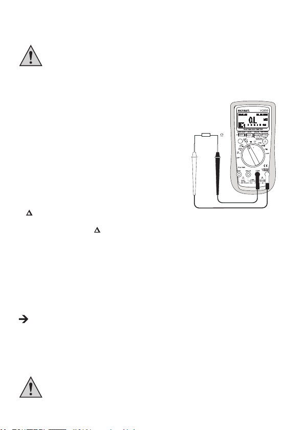
Zur Widerstandsmessung gehen Sie wie folgt vor:
1. Schalten Sie das DMM ein und wählen den Messbereich „Ω“.
2. Stecken Sie die rote Messleitung in die °CHzVΩ-
Messbuchse (7), die schwarze Messleitung in die COMMessbuchse (8) (Abb. 5).
3. Überprüfen Sie die Messleitungen auf Durchgang, indem
Sie die beiden Messspitzen verbinden. Daraufhin muss
sich ein Widerstandswert von ca. 0 – 1,5 Ω einstellen
(Eigenwiderstand der Messleitungen).
4. Bei niederohmigen Messungen drücken Sie die REL/
PC (Log/◄)-Taste (10c), um den Eigenwiderstand der
Messleitungen nicht in die folgende Widerstandsmessung
einießen zu lassen. Im Display erscheint das Delta-Symbol
und die Anzeige zeigt 0 Ω. Die automatische Bereichswahl
(AUTO) ist deaktiviert. Der Grundwert (Rel-Differenz) wird
neben dem Delta-Symbol angezeigt.
5. Verbinden Sie nun die beiden Messspitzen mit dem Messobjekt. Der Messwert wird, sofern das
Messobjekt nicht hochohmig oder unterbrochen ist, im Display angezeigt. Warten Sie, bis sich die
Anzeige stabilisiert hat. Bei Widerständen >1 MΩ kann dies einige Sekunden dauern.
6. Sobald „OL“ (für Overload = Überlauf) im Display erscheint, haben Sie den Messbereich
überschritten bzw. der Messkreis ist unterbrochen. Ein erneutes Drücken der REL/PC (Log/◄)-
Taste schaltet die Relativ-Funktion aus und aktiviert die Autorange-Funktion.
7. Entfernen Sie nach Messende die Messleitungen vom Messobjekt und schalten Sie das DMM aus.
Wenn Sie eine Widerstandsmessung durchführen, achten Sie darauf, dass die Messpunkte,
welche Sie mit den Messspitzen zum Messen berühren, frei von Schmutz, Öl, Lötlack oder
ähnlichem sind. Solche Umstände können das Messergebnis verfälschen.
Abb. 5
f) Diodentest
Vergewissern Sie sich, dass alle zu messenden Schaltungsteile, Schaltungen und
Bauelemente sowie andere Messobjekte unbedingt spannungslos und entladen
sind.
21
Page 20
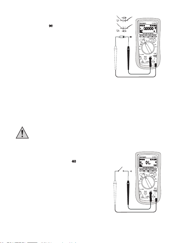
1. Schalten Sie das DMM ein und wählen den Messbereich „Ω“.
Drücken Sie die SHIFT/SETUP-Taste (3) bis im Display das
Diodentest-Symbol
2. Stecken Sie die rote Messleitung in die °CHzVΩ-
Messbuchse (7), die schwarze Messleitung in die COMMessbuchse (8) (Abb. 6).
3. Überprüfen Sie die Messleitungen auf Durchgang, indem Sie
die beiden Messspitzen verbinden. Daraufhin muss sich ein
Wert von ca. 0,0000 V einstellen.
4. Verbinden Sie die beiden Messspitzen mit dem Messobjekt
(Diode).
5. Im Display wird die Durchlassspannung „UF“ in Volt (V)
angezeigt. Ist „.OL“ ersichtlich, so wird die Diode in
Sperrrichtung (UR) gemessen oder die Diode ist defekt
(Unterbrechung). Führen Sie zur Kontrolle eine gegenpolige
Messung durch.
6. Entfernen Sie nach Messende die Messleitungen vom Messobjekt und schalten Sie das DMM aus.
erscheint.
Abb. 6
g) Durchgangsprüfung
Vergewissern Sie sich, dass alle zu messenden Schaltungsteile, Schaltungen und
Bauelemente sowie andere Messobjekte unbedingt spannungslos und entladen
sind.
1. Schalten Sie das DMM ein und wählen den Messbereich „Ω“.
Drücken Sie die SHIFT/SETUP-Taste (3) bis im Display das
Symbol für die Durchgangsprüfung
2. Stecken Sie die rote Messleitung in die °CHzVΩ-
Messbuchse (7), die schwarze Messleitung in die COMMessbuchse (8) (Abb. 7).
3. Als Durchgang wird ein Messwert <10 Ω erkannt und es
ertönt ein Piepton.
4. Sobald „OL.“ (für Overload = Überlauf) im Display erscheint,
haben Sie den Messbereich überschritten bzw. der Messkreis
ist unterbrochen.
5. Entfernen Sie nach Messende die Messleitungen vom
Messobjekt und schalten Sie das DMM aus.
erscheint.
Abb. 7
22
Page 21
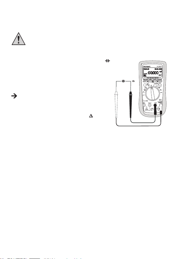
h) Kapazitätsmessung
Vergewissern Sie sich, dass alle zu messenden Schaltungsteile, Schaltungen und
Bauelemente sowie andere Messobjekte unbedingt spannungslos und entladen
sind.
Beachten Sie bei Elektrolyt-Kondensatoren unbedingt die Polarität.
1. Schalten Sie das DMM ein und wählen den Messbereich „
2. Stecken Sie die rote Messleitung in die °CHzVΩ-
Messbuchse (7), die schwarze Messleitung in die COMMessbuchse (8) (Abb. 8).
3. Im Display erscheint die Einheit „nF“.
Aufgrund des empndlichen Messeingangs kann es bei
„offenen“ Messleitungen zu einer Wertanzeige im Display
kommen. Durch Drücken der REL/PC (Log/◄)-Taste (10c)
wird die Anzeige auf „0“ gesetzt. Der Grundwert (RelDifferenz) wird neben dem Delta-Symbol angezeigt.
Die Autorange-Funktion wird deaktiviert.
4. Verbinden Sie nun die beiden Messspitzen (rot = Pluspol/
schwarz = Minuspol) mit dem Messobjekt (Kondensator).
Im Display wird nach einer kurzen Zeit die Kapazität
angezeigt. Warten Sie, bis sich die Anzeige stabilisiert hat.
Bei Kapazitäten >400 μF kann dies einige Sekunden dauern.
5. Sobald „OL“ (für Overload = Überlauf) im Display erscheint, haben Sie den Messbereich
überschritten.
6. Entfernen Sie nach Messende die Messleitungen vom Messobjekt und schalten Sie das DMM aus.
“.
Abb. 8
23
Page 22
i) Temperaturmessung
Während der Temperaturmessung darf nur der Temperaturfühler der zu messenden
Temperatur ausgesetzt werden. Die Arbeitstemperatur des Messgerätes darf nicht
über- oder unterschritten werden, da es sonst zu Messfehlern kommen kann.
Der Kontakt-Temperaturfühler darf nur an spannungsfreien Oberächen verwendet
werden.
Zur Temperaturmessung können alle K-Typ-Thermofühler verwendet werden. Die Temperatur wird
in °C und °F angezeigt. Der mitgelieferte Temperaturfühler ist für Messungen von -40 bis +400 °C
vorgesehen. Mit optionalen Fühlern kann der gesamte Messbereich (-40 bis +1000 °C) verwendet
werden.
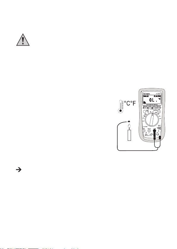
Zur Temperatur-Messung gehen Sie wie folgt vor:
1. Schalten Sie das DMM ein und wählen den Messbereich „°C“.
2. Drücken Sie die SHIFT/SETUP-Taste (3), um die Messfunktion
auf eine Anzeige in °F umzuschalten.
3. Stecken Sie den Thermofühler polungsrichtig mit dem Pluspol
in die °CHzVΩ-Messbuchse (7) und mit dem Minuspol in die
COM-Messbuchse (8) (Abb. 9).
4. In der Hauptanzeige erscheint der Temperaturwert in °C oder
°F, je nach Betätigung der SHIFT/SETUP-Taste.
5. Sobald „OL.“ im Display erscheint, wurde der Messbereich
(-40 bis +1000 °C) überschritten.
6. Entfernen Sie nach Messende den Fühler und schalten Sie
das DMM aus.
Bei überbrücktem Messeingang (Buchsen: °CHzVΩ – COM) wird die Gerätetemperatur
des DMM angezeigt. Die Temperaturanpassung an die Umgebung erfolgt auf Grund des
geschlossenen Gehäuses sehr langsam.
Abb. 9
24
Page 23
j) Wechselspannungsmessung mit 1 kHz-Tiefpasslter
Nutzen Sie die Tiefpasslteroption nie zum Prüfen des Vorhandenseins gefährlicher
Spannungen! Die vorhandenen Spannungen können unter Umständen höher sein
als angegeben. Führen Sie immer zuerst eine Spannungsmessung ohne den Filter
durch, um etwaige gefährliche Spannungen zu erkennen.
Das DMM ist mit einem Wechselstrom-Tiefpasslter ausgestattet. Es handelt sich hierbei um
eine Wechselspannungsmessung, die über einen Tiefpasslter geleitet wird, der unerwünschte
Spannungen oberhalb von 1 kHz blockiert.
Zur AC-Spannungsmessung mit dem Tiefpasslter gehen
Sie wie folgt vor:
1. Schalten Sie das DMM ein und wählen den Messbereich
„ V
“. Drücken Sie die SHIFT/SETUP-Taste (3), um in den
Messbereich „ ” umzuschalten.
2. Stecken Sie die rote Messleitung in die °CHzVΩ-
Messbuchse (7), die schwarze Messleitung in die COMMessbuchse (8) (Abb. 10).
3. Verbinden Sie die beiden Messspitzen mit dem Messobjekt
(Generator, Schaltung usw.). Der Messwert wird im Display
angezeigt.
4. Entfernen Sie nach Messende die Messleitungen vom
Messobjekt und schalten Sie das DMM aus.
Abb. 10
12. RANGE-FUNKTION, MANUELLE MESSBEREICHSWAHL
Die RANGE-Funktion ermöglicht in einigen Messfunktionen mit automatischer Messbereichswahl
(AUTO) die manuelle Messbereichswahl. In Grenzbereichen ist es sinnvoll den Messbereich zu
xieren, um ein ungewolltes Umschalten zu verhindern.
Drücken Sie die RANGE (-) Taste (10d), um zur manuellen Messbereichswahl zu wechseln. Bei
gewählter manueller Messbereichswahl erlischt die Anzeige „AUTO“ im Display.
Wählen Sie nun den gewünschten Messbereich aus, indem Sie mehrfach auf die RANGE (-) Taste
drücken.
Um wieder zur automatischen Messbereichswahl zu wechseln, halten Sie die RANGE (-) Taste für 2 s
gedrückt. „AUTO“ erscheint wieder im Display (vorausgesetzt die Autorange-Funktion ist in diesem
Messbereich möglich).
25
Page 24
13. REL-FUNKTION
Die REL-Funktion ermöglicht eine Bezugswertmessung, um evtl. Leitungsverluste wie z.B. bei
Widerstandsmessungen zu vermeiden. Hierzu wird der momentane Anzeigewert auf Null gesetzt. Ein
neuer Bezugswert wurde eingestellt. Der Grundwert (Rel-Differenz) wird neben dem Delta-Symbol
angezeigt.
Durch Drücken der REL/PC (Log/◄)-Taste (10c) wird diese Messfunktion aktiviert. Im Display
erscheint
Um diese Funktion abzuschalten, drücken Sie die REL/PC (Log/◄)-Taste erneut oder wechseln Sie
die Messfunktion.
. Die automatische Messbereichswahl wird dabei deaktiviert.
Die REL-Funktion ist nicht aktiv in den Messbereichen Temperatur, Durchgang-
sprüfung, Diodentest, Frequenz und bei der Tiefpasslter-Spannungsmessung.
14. HOLD-FUNKTION
Die HOLD-Funktion friert den momentan dargestellten Messwert ein, um diesen in Ruhe abzulesen
oder zu protokollieren.
Stellen Sie bei der Überprüfung von spannungsführenden Leitern sicher,
dass diese Funktion bei Testbeginn deaktiviert ist. Es wird sonst ein falsches
Messergebnis vorgetäuscht!
Zum Einschalten der Hold-Funktion drücken Sie die H/LIGHT (+/COMP)-Taste (10a); ein Signalton
bestätigt diese Aktion und es wird
Um die HOLD-Funktion abzuschalten, drücken Sie die H/LIGHT (+/COMP)-Taste erneut oder
wechseln Sie die Messfunktion.
im Display angezeigt.
15. MAX. / MIN. / AVG.-FUNKTION
Die MAX/MIN-Funktion ermöglicht während einer Messung die Maximal- und Minimalwerte zu erfassen
und anzuzeigen. Nach Aktivierung der MAX/MIN-Funktion wird wahlweise der Max- oder Min-Wert
festgehalten. Der aktuelle Messwert kann im oberen Bereich des Displays (unter dem Datum) weiterhin
abgelesen werden.
Durch Drücken der MAX/MIN (View/►)-Taste (10b) wird die MAX-Funktion eingeschaltet. Der Max-
Wert wird im Hauptdisplay fortlaufend festgehalten. Im Display erscheint das Symbol
Ein weiteres Drücken schaltet zur MIN-Funktion um. Der Min-Wert wird im Hauptdisplay fortlaufend
festgehalten. Erkennbar ist dieser Wert durch das Symbol
26
.
.
Page 25
Ein weiteres Drücken schaltet zur AVG-Funktion um. Der Mittelwert wird im Hauptdisplay fortlaufend
festgehalten. Erkennbar ist dieser Wert durch das Symbol
Um diese Funktion abzuschalten, halten Sie die MAX/MIN (View/►)-Taste ca. 2 s gedrückt.
Die MAX-MIN-Funktion ist nicht in allen Messfunktionen verfügbar.
.
16. LOW IMP. 400 KΩ –FUNKTION
Diese Funktion darf nur bei Spannungen bis max. 1000 V und nur bis max.
3 Sekunden verwendet werden!
Diese Funktion ermöglicht im Spannungsmessbereich das Herabsetzen der Messimpedanz von
10 MΩ auf 400 kΩ. Durch das Senken der Messimpedanz werden mögliche Phantomspannungen
unterdrückt, die das Messergebnis verfälschen könnten.
Drücken Sie die
Nach dem Loslassen hat das Multimeter wieder die normale Messimpedanz von 10 MΩ. Während die
Taste gedrückt wird ertönt ein Signalton und es erscheint die Displayanzeige .
-Taste (9) während der Spannungsmessung (max. 1000 V!) für max. 3 Sekunden.
17. VERGLEICHS-MODUS (COMP-MODE)
Bei der Vergleichsmessung wird nach Festlegung einer Ober- und Untergrenze der aktuellen
Messgröße in der Hauptanzeige nur noch der jeweilige Status des aktuellen Messwertes gegenüber
den eingestellten Bereichsgrenzen angezeigt.
Zur Einstellung der Grenzwerte des Vergleichsmodus gehen Sie wie folgt vor:
1. Schalten Sie das DMM ein und wählen den entsprechenden Messbereich.
2. Stecken Sie die Messleitungen in die jeweiligen Messbuchsen.
3. Halten Sie die SHIFT/SETUP-Taste (3) für ca. 2 s gedrückt. Auf dem Display erscheint
. Sie benden sich im SHIFT-Modus.
4. Halten Sie nun ein weiteres Mal die SHIFT/SETUP-Taste für ca. 2s gedrückt, um in das SETUPMenü zu gelangen.
5. Um die Obergrenze für den Vergleichsmodus einzustellen, drücken Sie mehrmals die SHIFT/
SETUP-Taste, bis der Menüpunkt „COMP MAX“ ausgewählt ist. Ein Stern-Symbol * links neben
dem Menüpunkt zeigt an, dass der Menüpunkt ausgewählt ist.
6. Mit Hilfe der Tasten REL/PC (Log/◄) und MAX/MIN (View/►) können Sie nun die einzelnen
Stellen anwählen und deren Wert mit den Tasten H/LIGHT (+/COMP) oder RANGE (-) verändern.
27
Page 26
7. Drücken Sie nach erfolgter Einstellung die SHIFT/SETUP-Taste, um die Untergrenze für den
Vergleichsmodus (Menüpunkt „COMP MIN“) einzustellen. Hier können Sie ebenfalls mit Hilfe der
Tasten REL/PC (Log/◄) und MAX/MIN (View/►) die einzelnen Stellen anwählen und deren Wert
mit den Tasten H/LIGHT (+/COMP) oder RANGE (-) verändern.
Die Grenzwerteinstellung besitzt keine Einheit. Der eigentliche Wert des Grenzwerts ergibt sich
aus dem bei der Messung eingestellten Bereich.
Beispiel:
Sie haben als Untergrenze „00900“ und als Obergrenze „01000“ im SETUP-Menü eingestellt.
Bei einer Vergleichsmessung im Messbereich „mV
„009.00 mV“ (Untergrenze); „010.00 mV“ (Obergrenze)
8. Drücken Sie nun die SHIFT/SETUP-Taste, um den Messstatus (Menüpunkt „COMP TYPE“)
festzulegen.
9. Drücken Sie die Tasten REL/PC (Log/◄) oder MAX/MIN (View/►), um „OUTER“ oder „INNER“
auszuwählen. Bei der Auswahl „OUTER“ wird der Messwert als bestanden (PASS) deklariert, der
sich außerhalb der Ober- und Untergrenze bendet; bei „INNER“ wird der Messwert als bestanden
(PASS) deklariert, der sich innerhalb der Ober- und Untergrenze bendet.
10. Halten Sie die SHIFT/SETUP-Taste für ca. 2 s gedrückt, um die Einstellungen zu speichern und
das SETUP-Menü zu verlassen.
Vergleichsmessung durchführen:
1. Wählen Sie den jeweiligen Messbereich.
2. Halten Sie die SHIFT/SETUP-Taste (3) für ca. 2 s gedrückt. Auf dem Display erscheint
benden sich nun im SHIFT-Modus.
3. Drücken Sie nun die H/LIGHT (+/COMP)-Taste (10a). Im Display erscheint das Symbol
und die eingestellten Grenzwerte.
Die automatische Messbereichswahl ist deaktiviert. Bevor Sie nun mit der Messung
beginnen, sollten Sie sichergehen, dass Sie den richtigen Messbereich eingestellt
haben. Diesen können Sie mit Hilfe der RANGE (-) Taste auswählen.
“ werden die Werte wie folgt angezeigt:
. Sie
4. Verbinden Sie die beiden Messspitzen mit dem Messobjekt.
5. Der Messwert wird mit der entsprechenden Einheit im Display angezeigt.
6. Im Display wird durch die Symbole
der aktuelle Messwert, je nach vorheriger Einstellung innerhalb oder außerhalb der eingestellten
Grenzwerte liegt.
7. Zum Beenden des Vergleichsmodus drücken Sie erneut die H/LIGHT (+/COMP)-Taste (10a).
28
(bestanden) und (nicht bestanden) signalisiert, ob
Page 27
18. MESSWERTE AUFZEICHNEN UND VERWALTEN
Das VC890 Digital-Multimeter bietet mit seiner Datenlogging-Funktion die Möglichkeit bis zu 1000
Messwerte aufzuzeichnen.
Um Messwerte manuell zu speichern, gehen Sie bitte wie folgt vor:
1. Halten Sie bei eingeschaltetem Messgerät die SHIFT/SETUP-Taste (3) für ca. 2 s gedrückt. Auf
dem Display erscheint
2. Drücken Sie nun die REL/PC (Log/◄)-Taste (10c), um den aktuell gemessenen Wert abzuspeichern.
Im Display erscheint das Symbol und darunter die erste Speichernummer „0001“.
3. Um einen weiteren Wert aufzuzeichnen, drücken Sie ein weiteres Mal auf die REL/PC (Log/◄)-
Taste. Die zweite Speichernummer „0002“ wird angezeigt.
4. Zum Verlassen des SHIFT-Modus drücken Sie die SHIFT/SETUP-Taste.
Wenn Sie ca. 3 Sekunden lang keinen Wert abspeichern, erlischt das Symbol und die
Speichernummer. Drücken Sie erneut auf die REL/PC (Log/◄)-Taste, um weitere Werte zu
speichern. Im Display erscheint wieder das Symbol und die Speichernummer.
Messwerte automatisch speichern:
1. Wählen Sie zuerst die gewünschte Aufzeichnungsrate im SETUP-Menü aus. Das Gerät ist im
Auslieferungszustand so eingestellt, dass es einen Messwert pro Sekunde speichert.
2. Halten Sie bei eingeschaltetem Messgerät die SHIFT/SETUP-Taste (3) für ca. 2 s gedrückt. Auf
dem Display erscheint
3. Halten Sie die SHIFT/SETUP-Taste erneut für ca. 2 s gedrückt, um das SETUP-Menü zu öffnen.
4. Drücken Sie nun mehrmals auf die SHIFT/SETUP-Taste, bis der Menüpunkt „LOGGER
SAMPLING RATE“ ausgewählt ist. Ein Stern-Symbol * links neben dem Menüpunkt zeigt an, dass
der Menüpunkt ausgewählt ist.
5. Drücken Sie die Tasten H/LIGHT (+/COMP) oder RANGE (-), um die Aufzeichnungsrate
einzustellen (Einstellbereich: 1 bis 10 Sekunden).
6. Halten Sie die SHIFT/SETUP-Taste für ca. 2 s gedrückt, um die Einstellung zu speichern und das
SETUP-Menü zu verlassen.
7. Um Messwerte aufzunehmen, müssen Sie in den SHIFT-Modus wechseln. Halten Sie bei
eingeschaltetem Messgerät die SHIFT/SETUP-Taste für ca. 2 s gedrückt, bis
angezeigt wird.
8. Halten Sie für ca. 2 s die REL/PC (Log/◄)-Taste gedrückt, um die automatische Aufzeichnung
zu starten. Auf dem Display erscheint
speichert nun die Messwerte mit der von Ihnen eingestellten Aufzeichnungsrate.
9. Zum Stoppen der Aufzeichnung halten Sie wieder die REL/PC (Log/◄)-Taste für ca. 2 s gedrückt.
. Sie benden sich nun im SHIFT-Modus.
. Sie benden sich nun im SHIFT-Modus.
im Display
und darunter die Speichernummer. Das Gerät
29
Page 28

10. Um die Aufzeichnung fortzuführen, halten Sie ein weiteres Mal die REL/PC (Log/◄)-Taste für
ca. 2 s gedrückt.
11. Zum Verlassen des SHIFT-Modus drücken Sie die SHIFT/SETUP-Taste.
Einstellungen für den Messwertespeicher:
1. Nehmen Sie die Einstellungen für den Messwertespeicher im SETUP-Menü vor.
2. Halten Sie bei eingeschaltetem Messgerät die SHIFT/SETUP-Taste (3) für ca. 2 s gedrückt. Auf
dem Display erscheint
3. Halten Sie die SHIFT/SETUP-Taste erneut für ca. 2 s gedrückt, um das SETUP-Menü zu öffnen.
4. Drücken Sie nun mehrmals auf die SHIFT/SETUP-Taste, bis der Menüpunkt „LOGGER MEMORY“
ausgewählt ist. Ein Stern-Symbol * links neben dem Menüpunkt, zeigt an dass der Menüpunkt
ausgewählt ist.
5. Drücken Sie die Tasten REL/PC (Log/◄) oder MAX/MIN (View/►), um „FIX“ oder „OVERWRITE“
auszuwählen.
6. Die Einstellung „FIX“ bedeutet, dass die Messwerte solange gespeichert werden, bis der Speicher
voll ist (max. 1000 Messwerte). Die Messung wird bei der Speichernummer „1000“ angehalten.
7. Die Einstellung „OVERWRITE“ bedeutet, dass die Messwerte fortlaufend gespeichert werden.
Sobald der Messwert „1000“ aufgezeichnet wurde, fängt das Gerät an, die Messwerte zu
überschreiben. Die Speichernummer wird nicht mehr im Display angezeigt. Stattdessen erscheint
ein blinkendes Unendlichkeits-Symbol „∞“.
8. Der Menüpunkt „LOGGER MEMORY“ ist im Auslieferungszustand auf „FIX“ voreingestellt.
9. Halten Sie die SHIFT/SETUP-Taste für ca. 2 s gedrückt, um die Einstellung zu speichern und das
SETUP-Menü zu verlassen.
Display-Einstellung für die automatische Messwertespeicherung:
1. Sie haben die Möglichkeit bei der automatischen Messung, den Energiespar-Modus zu aktivieren.
2. Nehmen Sie diese Einstellung im SETUP-Menü vor.
3. Halten Sie bei eingeschaltetem Messgerät die SHIFT/SETUP-Taste (3) für ca. 2 s gedrückt. Auf
dem Display erscheint
4. Halten Sie die SHIFT/SETUP-Taste erneut für ca. 2 s gedrückt, um das SETUP-Menü zu öffnen.
5. Drücken Sie nun mehrmals auf die SHIFT/SETUP-Taste, bis der Menüpunkt „LOGGER DATA
DISPLAY“ ausgewählt ist. Ein Stern-Symbol * links neben dem Menüpunkt zeigt an, dass der
Menüpunkt ausgewählt ist.
6. Drücken Sie die Tasten REL/PC (Log/◄) oder MAX/MIN (View/►), um „ON“ oder „OFF“
auszuwählen.
7. Die Einstellung „ON“ bedeutet, dass das Display während der automatisch fortlaufenden Messung
immer eingeschaltet ist.
30
. Sie benden sich nun im SHIFT-Modus.
. Sie benden sich nun im SHIFT-Modus.
Page 29
8. Die Einstellung „OFF“ bedeutet, dass sich das Display ausschaltet, wenn das Gerät 5 Minuten
lang nicht bedient wird. Es wird dann nur noch das Symbol
angezeigt. Wenn das Gerät kontinuierlich Messwerte speichert (Einstellung „OVERWRITE“) und
der Messwert „1000“ überschritten wird, erscheint ein blinkendes Unendlichkeits-Symbol „∞“
unterhalb von .
9. Das Gerät ist im Auslieferungszustand auf „OFF“ voreingestellt.
10. Halten Sie die SHIFT/SETUP-Taste für ca. 2 s gedrückt, um die Einstellung zu speichern und das
SETUP-Menü zu verlassen.
Wenn das Display im Energiespar-Modus ausgeschaltet wurde, betätigen Sie den Drehschalter
oder drücken Sie eine beliebige Taste (außer -Taste (9)), um es wieder einzuschalten.
Gespeicherte Messwerte ansehen:
1. Halten Sie bei eingeschaltetem Messgerät die SHIFT/SETUP-Taste (3) für ca. 2 s gedrückt. Auf
dem Display erscheint
2. Drücken Sie nun die MAX/MIN (View/►)-Taste (10b), um in den Anzeige-Modus zu wechseln. Im
Display erscheint
wird der gespeicherte Messwert angezeigt.
3. Betätigen Sie die Tasten H/LIGHT (+/COMP) oder RANGE (-), um die einzelnen Aufzeichnungen
anzuzeigen.
4. Drücken Sie erneut die MAX/MIN (View/►)-Taste, um den Anzeige-Modus zu verlassen.
5. Zum Verlassen des SHIFT-Modus drücken Sie die SHIFT/SETUP-Taste.
Die gespeicherten Messwerte einer Vergleichsmessung werden im Display mit den Symbolen
und angezeigt.
Wenn im Display „VOID“ angezeigt wird, bedeutet dies, dass der Messwerte-Speicher leer ist.
Gespeicherte Messwerte löschen:
1. Halten Sie bei eingeschaltetem Messgerät die SHIFT/SETUP-Taste (3) für ca. 2 s gedrückt. Auf
dem Display erscheint
2. Halten Sie die MAX/MIN (View/►)-Taste (10b) für ca. 2 s gedrückt. Es erscheint kurz die Anzeige
und „VOID“ auf dem Display. Es werden alle Messwerte gelöscht.
3. Zum Verlassen des SHIFT-Modus drücken Sie die SHIFT/SETUP-Taste.
. Sie benden sich nun im SHIFT-Modus.
und darunter die erste Speichernummer „0001“. In der Mitte des Displays
. Sie benden sich nun im SHIFT-Modus.
und die Speichernummer
31
Page 30
19. AUTO-POWER-OFF-FUNKTION
1. Das DMM schaltet nach einer bestimmten Zeit automatisch ab, wenn keine Taste oder der
Drehschalter betätigt wurde. Diese Funktion schützt und schont die Batterie und verlängert die
Betriebszeit.
2. Sie können eine Abschaltzeit im SETUP-Menü einstellen. Das Gerät ist im Auslieferungszustand
auf 5 Minuten voreingestellt.
3. Halten Sie bei eingeschaltetem Messgerät die SHIFT/SETUP-Taste (3) für ca. 2 s gedrückt. Auf
dem Display erscheint
4. Halten Sie die SHIFT/SETUP-Taste erneut für ca. 2 s gedrückt, um das SETUP-Menü zu öffnen.
5. Drücken Sie nun mehrmals auf die SHIFT/SETUP-Taste, bis der Menüpunkt „APO TIME“
ausgewählt ist. Ein Stern-Symbol * links neben dem Menüpunkt zeigt an, dass der Menüpunkt
ausgewählt ist.
6. Drücken Sie die Tasten REL/PC (Log/◄) und MAX/MIN (View/►), um die Abschaltzeit
einzustellen. Zur Auswahl stehen: 5 MIN, 15 MIN, 30 MIN oder OFF (AUS). Die Einstellung „OFF“
bedeutet, dass die Auto-Power-Off-Funktion deaktiviert ist.
7. Halten Sie die SHIFT/SETUP-Taste für ca. 2 s gedrückt, um die Einstellung zu speichern und das
SETUP-Menü zu verlassen.
8. Wenn Sie eine Abschaltzeit eingestellt haben, wird im Display das Symbol
Um das DMM nach einer automatischen Abschaltung wieder einzuschalten, betätigen Sie den
Drehschalter oder drücken Sie eine beliebige Taste (außer -Taste (9)).
Die Auto-Power-Off-Funktion wird bei der Datenübertragung zum PC deaktiviert, um die
Datenverbindung nicht zu unterbrechen. Die Auto-Power-Off-Funktion ist solange inaktiv, bis
die Datenübertragung zum PC (per optischer Schnittstelle) wieder abgeschaltet wird.
Die Auto-Power-Off-Funktion wird auch bei der automatischen Aufzeichnung von Messwerten
deaktiviert.
. Sie benden sich nun im SHIFT-Modus.
angezeigt.
20. OPTISCHE SCHNITTSTELLE
An der Rückseite des Messgerätes ist eine optisch isolierte Schnittstelle (11) integriert, mit der
Messdaten zu einem Computer übertragen und weiterverarbeitet werden können.
Die Datenverbindung kann mit dem mitgelieferten USB-Schnittstellenadapter mit einer freien USB-
Schnittstelle an Ihrem Computer hergestellt werden (auf dem Computer muss die entsprechende
Software „Voltsoft“ bereits installiert sein).
Schieben Sie die Schnittstellenabdeckung nach oben vom Gehäuse. Setzen Sie den keilförmigen
Adapter des Schnittstellenkabels von oben bündig in die Gehäusenut am Messgerät.
Stecken Sie dann den USB-Stecker des Typs A am anderen Ende des Schnittstellenkabels in einen
freien USB-Anschluss am Computer.
32
Page 31

Die Schnittstelle ist im Normalbetrieb abgeschaltet. Um diese zu aktivieren, halten Sie bei
eingeschaltetem DMM die REL/PC (Log/◄)-Taste (10c) für 2 s gedrückt. Die Aktivierung wird durch
das Schnittstellensymbol
2 s gedrückt oder schalten das DMM aus.
signalisiert. Zum Deaktivieren halten Sie die REL/PC (Log/◄)-Taste ca.
21. INSTALLATION DER SOFTWARE
1. Legen Sie die CD in das CD-Rom-Laufwerk Ihres Computers ein.
2. Die Installation beginnt automatisch. Falls nicht, gehen Sie bitte in Ihr CD-ROM-Verzeichnis und
öffnen Sie dort die Installationsdatei „autorun.exe“.
3. Wählen Sie Ihre gewünschte Sprache aus (Deutsch, Englisch oder Französisch).
4. Folgen Sie den Anweisungen im Dialogfenster, wählen Sie das Zielverzeichnis für die Installation
aus und führen Sie die Installation durch.
5. Beachten Sie für nähere Informationen bitte die auf der CD enthaltene Bedienungsanleitung.
6. Bei der beiliegenden Software handelt es sich um die Voltsoft Standard Edition. Die Professional
Version (Voltsoft PRO, Nr. 10 13 33) kann separat erworben werden. Mit Erwerb der Professional
Version erhalten Sie den entsprechenden Lizenzschlüssel. Folgen Sie den Anweisungsschritten
der Voltsoft Bedienungsanleitung, um ein Upgrade Ihrer Software zur Professional Version
durchzuführen und diese zu registrieren.
7. Voltsoft Software-Updates auf die neueste Version des Voltsoft Programms sind verfügbar, wenn
das Programm läuft und eine Internetverbindung besteht; alternativ können Sie auch unter „http://
www.conrad.com“ nach den neuesten Voltsoft-Updates suchen.
22. DISPLAYHELLIGKEIT
1. Die Helligkeit des Displays kann stufenweise eingestellt werden. Halten Sie die H/LIGHT (+/
COMP) -Taste (10a) für ca. 2 s gedrückt, um zwischen 3 Helligkeits-Stufen zu wechseln.
2. Im SETUP-Menü haben Sie die Möglichkeit, den Energiespar-Modus für das Display zu aktivieren
bzw. zu deaktivieren. Der Energiespar-Modus ist im Auslieferungszustand des Gerätes aktiviert.
3. Ist der Energiespar-Modus eingeschaltet, so wird die Displayhelligkeit bei Inaktivität automatisch
reduziert. Wenn das Gerät 15 Sekunden lang nicht bedient wird, wechselt die Displayhelligkeit
von der höchsten Helligkeits-Stufe auf die mittlere Stufe. Nach weiteren 15 Sekunden Inaktivität
wechselt das Display von der mittleren Stufe auf die niedrigste Stufe.
4. Halten Sie bei eingeschaltetem Messgerät die SHIFT/SETUP-Taste (3) für ca. 2 s gedrückt. Auf
dem Display erscheint
5. Halten Sie die SHIFT/SETUP-Taste erneut für ca. 2 s gedrückt, um das SETUP-Menü zu öffnen.
. Sie benden sich nun im SHIFT-Modus.
33
Page 32

6. Drücken Sie nun mehrmals auf die SHIFT/SETUP-Taste, bis der Menüpunkt „AUTO
BRIGTHNESS“ ausgewählt ist. Ein Stern-Symbol * links neben dem Menüpunkt zeigt an, dass
der Menüpunkt ausgewählt ist.
7. Drücken Sie die Tasten REL/PC (Log/◄) oder MAX/MIN (View/►), um „ON“ oder „OFF“
auszuwählen.
8. Die Einstellung „ON“ bedeutet, dass der Energiespar-Modus aktiviert ist. Die Helligkeit des
Displays wird bei Inaktivität automatisch reduziert.
9. Die Einstellung „OFF“ schaltet den Energiespar-Modus aus.
10. Halten Sie die SHIFT/SETUP-Taste für ca. 2 s gedrückt, um die Einstellung zu speichern und das
SETUP-Menü zu verlassen.
23. WARTUNG UND REINIGUNG
a) Allgemein
Um die Genauigkeit des Multimeters über einen längeren Zeitraum zu gewährleisten, sollte es jährlich
einmal kalibriert werden.
Das Messgerät ist bis auf eine gelegentliche Reinigung und den Sicherungswechsel absolut
wartungsfrei.
Den Sicherungs- und Batteriewechsel nden Sie im Anschluss.
Überprüfen Sie regelmäßig die technische Sicherheit des Gerätes und der
Messleitungen z.B. auf Beschädigung des Gehäuses oder Quetschung usw.
b) Reinigung
Bevor Sie das Gerät reinigen beachten Sie unbedingt folgende Sicherheitshinweise:
Beim Öffnen von Abdeckungen oder Entfernen von Teilen, außer wenn dies von
Hand möglich ist, können spannungsführende Teile freigelegt werden.
Vor einer Reinigung oder Instandsetzung müssen die angeschlossenen Leitungen
vom Messgerät und von allen Messobjekten getrennt werden. Schalten Sie das
DMM aus.
Verwenden Sie zur Reinigung keine carbonhaltigen Reinigungsmittel, Benzine, Alkohole oder
ähnliches. Dadurch wird die Oberäche des Messgerätes angegriffen. Außerdem sind die Dämpfe
gesundheitsschädlich und explosiv. Verwenden Sie zur Reinigung auch keine scharfkantigen
Werkzeuge, Schraubendreher oder Metallbürsten o.a.
34
Page 33

Zur Reinigung des Gerätes bzw. des Displays und der Messleitungen nehmen Sie ein sauberes,
fusselfreies, antistatisches und leicht feuchtes Reinigungstuch. Lassen Sie das Gerät komplett
abtrocknen, bevor Sie es für den nächsten Messeinsatz verwenden.
c) Messgerät öffnen
Ein Sicherungs- und Batteriewechsel ist aus Sicherheitsgründen nur möglich, wenn alle Messleitungen
vom Messgerät entfernt wurden. Das Batterie- und Sicherungsfach lässt sich bei eingesteckten
Messleitungen nicht öffnen.
Zusätzlich werden beim Öffnen alle Messbuchsen mechanisch verriegelt, um das nachträgliche
Einstecken der Messleitungen bei geöffnetem Gehäuse zu verhindern. Die Verriegelung wird
automatisch aufgehoben, wenn das Batterie- und Sicherungsfach wieder verschlossen ist.
Das Gehäusedesign lässt selbst bei geöffnetem Batterie- und Sicherungsfach nur den Zugriff auf
Batterie und Sicherungen zu. Das Gehäuse muss nicht mehr wie üblich komplett geöffnet und zerlegt
werden. Diese Maßnahmen erhöhen die Sicherheit und Bedienungsfreundlichkeit für den Anwender.
Zum Öffnen gehen Sie wie folgt vor:
1. Entfernen Sie alle Messleitungen vom Messgerät und
schalten es aus.
2. Lösen und entfernen Sie die rückseitige Batteriefach-
schraube (15).
3. Klappen Sie den Aufstellbügel (13) auf. Ziehen Sie den Batterie- und Sicherungsfachdeckel nach unten vom Messgerät
(Abb. 11).
4. Die Sicherungen und das Batteriefach sind jetzt zugänglich.
5. Verschließen Sie das Gehäuse in umgekehrter Reihenfolge
und verschrauben Sie das Batterie- und Sicherungsfach.
6. Das Messgerät ist wieder einsatzbereit.
Abb. 11
35
Page 34

d) Sicherungscheck/Sicherungswechsel
Die Strommessbereiche sind mit Hochleistungssicherungen abgesichert. Ist keine Messung in
diesem Bereich mehr möglich, muss die Sicherung ausgewechselt werden.
Das Messgerät ermöglicht die Prüfung der Sicherungen bei geschlossenem Gehäuse.
Zur Prüfung gehen Sie wie folgt vor:
1. Wählen Sie am Drehschalter den Messbereich „Ω“
2. Stecken Sie eine Messleitung in die °CHzVΩ-Buchse (7).
3. Kontaktieren Sie mit der Prüfspitze die zu prüfende Strom-
Messbuchse (Abb. 12).
4. Wird ein Messwert angezeigt, so ist die Sicherung ok. Bleibt
jedoch „OL“ in der Anzeige stehen, so ist die entsprechende
Sicherung defekt und muss ausgewechselt werden.
Zum Auswechseln gehen Sie wie folgt vor:
1. Trennen Sie die angeschlossenen Messleitungen vom Messkreis und von Ihrem Messgerät.
Schalten Sie das DMM aus.
2. Öffnen Sie das Gehäuse wie im Abschnitt „c) Messgerät öffnen“ (Seite 35) beschrieben.
3. Ersetzen Sie die defekte Sicherung gegen eine neue desselben Typs und Nennstromstärke oder
Baugleiche. Die Sicherungen haben folgende Werte:
Sicherung F1 F2
Nenndaten F600mA H 1000V F10A H 1000V
Schaltvermögen 30 kA
Abmessung (ø x L) 6,35 x 31,8 mm 10,3 x 38 mm
Bestellnummer 44 24 03 44 23 35
4. Verschließen Sie das Gehäuse wieder sorgfältig.
Die Verwendung geickter Sicherungen oder das Überbrücken des
Sicherungshalters ist aus Sicherheitsgründen nicht zulässig. Dies kann zum Brand
oder zur Lichtbogenexplosion führen. Betreiben Sie das Messgerät auf keinen Fall
im geöffneten Zustand.
36
Abb. 12
Page 35

e) Knopfbatterie wechseln
Wenn Datum und Uhrzeit nicht mehr korrekt angezeigt werden, muss die Knopfbatterie ersetzt
werden.
Zum Wechseln gehen Sie wie folgt vor:
1. Trennen Sie die angeschlossenen Messleitungen vom Messkreis und von Ihrem Messgerät.
Schalten Sie das DMM aus.
2. Öffnen Sie das Batterie- und Sicherungsfach wie im Abschnitt „c) Messgerät öffnen“ (Seite 35)
beschrieben.
3. Lösen Sie dann die vier Schrauben auf der Rückseite des Geräts, und ziehen Sie vorsichtig das
Gehäuse ab.
4. Schieben Sie die Knopfbatterie vorsichtig von unten aus der Batteriehalterung heraus. Heben Sie
dabei den Batteriehalter leicht nach oben an.
5. Ersetzen Sie die verbrauchte Knopfbatterie gegen eine neue desselben Typs (CR2032). Setzen
Sie eine neue Knopfbatterie in das Batteriefach ein. Achten Sie darauf, dass der Pluspol nach
oben zeigt.
6. Verschließen Sie das Gehäuse in umgekehrter Reihenfolge und verschrauben Sie das Batterieund Sicherungsfach.
Eine passende Knopfbatterie erhalten Sie unter folgender Bestellnummer:
Best.-Nr. 650183
37
Page 36

24. ENTSORGUNG
a) Produkt
Elektronische Geräte sind Wertstoffe und gehören nicht in den Hausmüll.
Entsorgen Sie das Produkt am Ende seiner Lebensdauer gemäß den geltenden
gesetzlichen Bestimmungen.
Entnehmen Sie evtl. eingelegte Batterien/Akkus und entsorgen Sie diese getrennt vom
Produkt.
b) Batterien / Akkus
Sie als Endverbraucher sind gesetzlich (Batterieverordnung) zur Rückgabe aller gebrauchten
Batterien/Akkus verpichtet; eine Entsorgung über den Hausmüll ist untersagt.
Schadstoffhaltige Batterien/Akkus sind mit dem nebenstehenden Symbol gekennzeichnet,
das auf das Verbot der Entsorgung über den Hausmüll hinweist. Die Bezeichnungen für
das ausschlaggebende Schwermetall sind: Cd=Cadmium, Hg=Quecksilber, Pb=Blei (die
Bezeichnung steht auf den Batterien/Akkus z.B. unter dem links abgebildeten Mülltonnen-
Symbol).
Ihre verbrauchten Batterien/Akkus können Sie unentgeltlich bei den Sammelstellen Ihrer
Gemeinde, unseren Filialen oder überall dort abgeben, wo Batterien/Akkus verkauft
werden.
Sie erfüllen damit die gesetzlichen Verpichtungen und leisten Ihren Beitrag zum Umweltschutz.
25. BEHEBUNG VON STÖRUNGEN
Mit dem DMM haben Sie ein Produkt erworben, welches nach dem neuesten Stand der Technik
gebaut wurde und betriebssicher ist.
Dennoch kann es zu Problemen oder Störungen kommen.
Deshalb möchten wir Ihnen hier beschreiben, wie Sie mögliche Störungen leicht selbst beheben
können:
Beachten Sie unbedingt die Sicherheitshinweise!
38
Page 37

Fehler Mögliche Ursache Mögliche Abhilfe
Das Multimeter funktioniert
nicht.
Keine Messwertänderung. Ist eine falsche Messfunktion
Das Messgerät piept und
es wird eine der folgenden
Warnmeldungen angezeigt:
ERROR ON V INPUT
ERROR ON A INPUT
ERROR ON mA INPUT
Andere Reparaturen als zuvor beschrieben sind ausschließlich durch einen
autorisierten Fachmann durchzuführen.
Ist die Batterie verbraucht? Kontrollieren Sie den Zustand.
Batteriewechsel.
aktiv (AC/DC)?
Stecken die Messleitungen
zuverlässig in den Messbuchsen?
Ist die Sicherung defekt? Kontrollieren Sie die
Ist die Hold-Funktion aktiviert?
)
(Anzeige
Falsch angeschlossene oder
ungeeignete Messleitungen
Kontrollieren Sie die Anzeige
(AC/DC) und schalten die
Funktion ggf. um.
Kontrollieren Sie den Sitz der
Messleitungen.
Sicherungen.
Drücken Sie die H/LIGHT
(+/COMP) -Taste um diese
Funktion zu deaktivieren.
Messleitungen richtig am
Messgerät anschließen,
austauschen oder Messfunktion
ändern.
39
Page 38

26. TECHNISCHE DATEN
Anzeige ................................Max. 60000 Counts (Zeichen)
Messrate .............................. ca. 2 – 3 Messungen/Sekunde,
Messleitungslänge ...............je ca. 90 cm
Messimpedanz ....................>10 MΩ (V-Bereich)
Betriebsspannung ................9 V Blockbatterie
Arbeitsbedingungen .............0 bis +30 ºC (<75 % rF), +30 bis +40 ºC (<50 % rF)
Betriebshöhe .......................max. 2000 m
Lagertemperatur ..................-10 bis +50 ºC
Gewicht ................................ca. 380 g
Abmessungen (L x B x T) ....185 x 91 x 43 mm
Überspannungskategorie ....CAT III 1000 V, CAT IV 600 V, Verschmutzungsgrad 2
z= -2 + 2i = sqrt(8)
Messtoleranzen
Angabe der Genauigkeit in ± (% der Ablesung + Anzeigefehler in Counts (= Anzahl der kleinsten
Stellen)). Die Genauigkeit gilt ein Jahr lang bei einer Temperatur von +23 °C (± 5 °C), bei einer rel.
Luftfeuchtigkeit von kleiner als 75 %, nicht kondensierend. Temperaturkoefzient: +0,1 x (spezizierte
Genauigkeit)/1 °C
Gleichspannung
Bereich Genauigkeit Auösung
600 mV ±(0,03 % + 10 Digit) 0,01 mV
6 V
60 V 0,001 V
600 V 0,01 V
1000 V 0,1 V
Überlastschutz: 1000 V; Impedanz: 10 MΩ
Bargraph: ca. 2 – 3 Messungen/Sekunde
0,0001 V
±(0,05 % + 10 Digit)
40
Page 39

Wechselspannung
Bereich Auösung Genauigkeit Frequenzbereich
6 V 0,0001 V
60 V 0,001 V
600 V 0,01 V
1000 V 0,1 V
Überlastschutz: 1000 V; Impedanz: ca. 10 MΩ
TrueRMS im Messbereich von 10 – 100 %
Scheitelfaktor (Crest Factor): max. 3,0 (bei 1000 V max. 1,5)
Messfunktion AC + DC Spannung
Bereich Auösung Genauigkeit Frequenzbereich
6 V 0,0001 V
60 V 0,001 V
600 V 0,01 V
1000 V 0,1 V
Überlastschutz: 1000 V; Impedanz: 10 MΩ
±(0,5 % + 40 Digit) 45 Hz – 1 kHz
±(1,2 % + 40 Digit) 1 kHz - 10 kHz
±(3 % + 40 Digit) 10 kHz - 20 kHz
±(4 % + 40 Digit) 20 kHz - 100 kHz
±(0,5 % + 40 Digit) 45 Hz - 1kHz
±(1,2 % + 40 Digit) 1 kHz - 10 kHz
±(3 % + 40 Digit) 10 kHz - 20 kHz
±(6 % + 40 Digit) 20 kHz - 100 kHz
±(0,5 % + 40 Digit) 45 Hz - 1kHz
±(1,2 % + 40 Digit) 1 kHz - 10 kHz
±(3 % + 40 Digit) 10 kHz - 20 kHz
nicht speziziert 20 kHz - 100 kHz
±(1,2 % + 40 Digit) 45 Hz - 1kHz
±(3 % + 40 Digit) 1 kHz - 5 kHz
±(6 % + 40 Digit) 5 kHz - 10 kHz
nicht speziziert 10 kHz - 100 kHz
±(1 % + 80 Digit) 45 Hz - 1 kHz
±(3 % + 40 Digit) 1 kHz - 10 kHz
±(6 % + 40 Digit) 10 kHz - 35 kHz
±(1 % + 80 Digit) 45 Hz - 1 kHz
±(3 % + 40 Digit) 1 kHz - 10 kHz
±(6 % + 40 Digit) 10 kHz - 35 kHz
±(1 % + 80 Digit) 45 Hz - 1 kHz
nicht speziziert 1 kHz - 10 kHz
nicht speziziert 10 kHz - 35 kHz
±(1,2 % + 80 Digit) 45 Hz - 1 kHz
nicht speziziert 1 kHz - 10 kHz
nicht speziziert 10 kHz - 35 kHz
41
Page 40

Gleichstrom
Bereich Genauigkeit Auösung
600 μA ±(0,3 % + 10 Digit) 0,01 μA
6000 μA
60 mA 0,001 mA
600mA 0,01 mA
10 A ±(1,5 % + 20 Digit) 0,001 A
Überlastschutz: Sicherungen; Messzeitbegrenzung >5 A: max. 10 s mit Pause von 10 min
Wechselstrom
Bereich Auösung Genauigkeit Frequenzbereich
600 µA 0,01 μA
6000 μA 0,1 μA
60 mA 0,001 mA
600 mA 0,01 mA
10 A 0,001 A
Überlastschutz: Sicherungen; Messzeitbegrenzung >5 A: max. 10 s mit Pause von 10 min;
Überlastschutz: 1000 V; TrueRMS im Messbereich von 10 – 100 %
Widerstand
Bereich Genauigkeit Auösung
600 Ω ±(1,0 % + 10 Digit) mit REL-Funktion 0,01 Ω
6 kΩ
60 kΩ 0,001 kΩ
600 kΩ 0,01 kΩ
6 MΩ ±(1,2 % + 10 Digit) 0,0001 MΩ
60 MΩ ±(2 % + 5 Digit) 0,001 MΩ
Überlastschutz: 1000 V
±(0,6 % + 10 Digit)
±(0,5 % + 10 Digit)
±(0,6 % + 40 Digit) 45 Hz - 1 kHz
±(1,2 % + 40 Digit) 1 kHz - 10 kHz
±(0,6 % + 40 Digit) 45 Hz - 1 kHz
±(1,2 % + 40 Digit) 1 kHz - 10 kHz
±(0,6 % + 40 Digit) 45 Hz - 1 kHz
±(1,2 % + 40 Digit) 1 kHz - 10 kHz
±(0,6 % + 40 Digit) 45 Hz - 1 kHz
±(1,2 % + 40 Digit) 1 kHz - 10 kHz
±(2 % + 40 Digit)
±(4 % + 40 Digit) 1 kHz - 10 kHz
0,1 μA
45 Hz - 1 kHz
0,0001 kΩ
42
Page 41

Kapazität
Bereich Genauigkeit Auösung
60 nF ±(2,5 % + 20 Digit) 0,001 nF
600 nF
6 μF 0,0001 μF
60 μF 0,001 μF
600 μF 0,01 μF
6000 μF ±(5 % + 20 Digit) 0,1 μF
60 mF nicht speziziert 0,001 mF
Überlastschutz: 1000 V
Frequenz
Bereich Genauigkeit Auösung
60 Hz
600 Hz 0,01 Hz
6 kHz 0,0001 kHz
60 kHz 0,001 kHz
600 kHz 0,01 kHz
6 MHz 0,0001 MHz
60 MHz 0,001 MHz
Überlastschutz: 1000 V;
Für 10 Hz – 60 MHz, Eingangsamplitude a: 1 Vrms ≤ a ≤ 30 Vrms
Duty-Cycle (Puls-Pausenverhältnis)
Bereich Genauigkeit Auösung
10 Hz – 2 kHz
(10 % – 90 %)
Überlastschutz: 1000 V
±(2,0 % + 20 Digit)
±(0,02 % + 8 Digit)
±(1,2 % + 30 Digit)
0,01 nF
0,001 Hz
0,01 %
43
Page 42

Temperatur
Bereich Genauigkeit Auösung
-40 bis +40 ºC ±(3 % + 20 Digit)
0,1 ºC+40 bis +400 ºC ±(2 % + 20 Digit)
+400 bis +1000 ºC ± 2,5 %
-40 bis +32 ºF ±(2,5 % + 40 Digit)
0,2 ºF+32 bis +752 ºF ±(1,5 % + 40 Digit)
+752 bis +1832 ºF ± 2,5 %
Überlastschutz: 1000 V
Diodentest
Prüfspannung Auösung
3,1 V 0,0001 V
Überlastschutz: 1000 V
Akust. Durchgangsprüfer
Auösung: 0,01 Ω
Überlastschutz: 1000 V, <10 Ω Dauerton
Tiefpasslter-Test
Bereich Auösung Bemerkungen
6 V 0,0001 V Filter für Wechselspannungssignal größer
60 V 0,001 V
600 V 0,01 V
1000 V 0,1 V
als 1 kHz.
44
Page 43

TABLE OF CONTENTS
Page
1. Introduction .................................................................................................................................. 46
2. Intended use ................................................................................................................................ 47
3. Operating elements ...................................................................................................................... 48
4. Symbol explanation ...................................................................................................................... 50
5. Safety instructions ........................................................................................................................ 51
6. Product description ...................................................................................................................... 54
7. Delivery content ........................................................................................................................... 54
8. Display indications and symbols .................................................................................................. 55
9. Battery .......................................................................................................................................... 56
10. Setting the time and date ............................................................................................................. 57
11. Measuring ................................................................................................................................... 58
12. RANGE function, manual measuring range selection .................................................................. 66
13. REL function ................................................................................................................................. 67
14. Hold function ................................................................................................................................ 67
15. MAX. / MIN. / AVG. function ......................................................................................................... 67
16. Low Imp. 400 KΩ function ........................................................................................................... 68
17. Comparison mode (Comp mode) ................................................................................................. 68
18. Recording and managing measured values ................................................................................. 70
19. Auto Power Off function ............................................................................................................... 73
20. Optical interface ........................................................................................................................... 73
21. Software installation ..................................................................................................................... 74
22. Display brightness ........................................................................................................................ 74
23. Maintenance and cleaning ........................................................................................................... 75
24. Disposal ....................................................................................................................................... 79
25. Troubleshooting ............................................................................................................................ 79
26. Technical data .............................................................................................................................. 81
45
Page 44

1. INTRODUCTION
Dear Customer,
In purchasing this Voltcraft® product, you have made a very good decision for which we would like
to thank you.
Voltcraft® - In the eld of measuring, charging and network technology, this name stands for
high-quality products which perform superbly and which are created by experts whose concern is
continuous innovation.
From the ambitious hobby electronics enthusiast to the professional user, products from the Voltcraft®
brand family provide the optimum solution even for the most demanding tasks. And the remarkable
feature is: we offer you the mature technology and reliable quality of our Voltcraft® products at
an almost unbeatable price-performance ratio. In this way, we aim to establish a long, fruitful and
successful co-operation with our customers.
We wish you a great deal of enjoyment with your new Voltcraft® product!
All names of companies and products are trademarks of the respective owner. All rights
reserved.
If there are any technical questions, please contact:
International: www.conrad.com/contact
United Kingdom: www.conrad-electronic.co.uk/contact
46
Page 45

2. INTENDED USE
• Measuring and displaying electric parameters in the range of overvoltage category CAT IV up to
max. 600 V or CAT III up to max. 1000 V against ground potential, pursuant to EN 61010-1 and all
lower categories.
• Measurement of direct and alternating voltage up to max. 1000 V
• Measurement of direct and alternating currents up to max. 10 A
• Frequency measuring up to 60 MHz
• Measurement of capacities up to 60 mF
• Measurement of resistances up to 60 MΩ
• Continuity test (<10 Ω acoustic)
• Diode test
• Measurement of temperature from -40 to +1000 ºC
• Display of duty cycle in % (10 – 90 %)
• 1 kHz low pass lter alternating voltage measurement
• Comparison value measurement
• Data memory and data logger for 1000 values with time stamp
• Data transmission to a PC via optical interface
• Date and time display
The measuring functions are selected using the rotary switch. The measuring range selection is
automatic for all measuring functions (except for diode and continuity test). Manual setting is possible
at any time.
The VC890 displays true RMS in both the direct and alternating voltage and current range.
For negative values, the polarity will automatically be displayed with the sign (-).
The two current measuring inputs are secured against overload with ceramic high-performance fuses.
The voltage in the current measuring circuit may not exceed 1000 V in CAT lll or 600 V in CAT IV.
A low impedance (Low Imp) function allows measurement with reduced internal resistance. This
suppresses phantom voltages which could appear in high-resistance measurements. Measurement
with reduced impedance is only permitted in measuring circuits up to max. 1000 V and only for max.
3 s. When the Low Imp button is pressed, a signal will sound and a warning indicator will be displayed.
The multimeter is powered by a standard 9 V alkaline or lithium monobloc battery. Operation is only
permitted with the specied battery type. An automatic power off prevents the battery from draining
prematurely if the device is not used for a period of time (settings: 5 min., 15 min., 30 min. or OFF;
see Chapter “19. Auto Power Off function”). The Auto Power Off function is switched off during data
transmission to a PC via optical interface.
47
Page 46

Do not operate the multimeter when it is open, when the battery compartment is open, or the battery
compartment lid is missing. The safety mechanism prevents the opening of the battery and fuse lid
when test leads are plugged into the measurement sockets. It also prevents test leads from being
plugged in when the battery and fuse lid is open.
Measurements in damp rooms or under unfavourable environmental conditions are not permitted.
Unfavourable environmental conditions are: dampness or high humidity, dust and ammable gases,
vapours or solvents, as well as thunderstorms or similar conditions such as strong electrostatic elds,
etc.
Use only test leads or measurement accessories which meet the specications of the multimeter.
For safety and approval purposes (CE), you must not rebuild and/or modify this product. If you use
the product for purposes other than those described above, the product may be damaged. In addition,
improper use can cause hazards such as short circuiting, re, electric shock etc. Read the instructions
carefully and keep them. Make this product available to third parties only together with its operating
instructions.
Observe all safety notes and information given in these instructions.
3. OPERATING ELEMENTS
See the fold-out page.
1 Rubber protective frame
2 Display
3 SHIFT/SETUP button
Switch the measuring function (red symbol on the rotary switch) /
switch function of the buttons (blue button labels)
4 Rotary switch for measurement function selection
5 mAμA measurement socket
6 10 A measurement socket
7 °CHzVΩ measurement socket (for “plus” of the same size)
8 COM measurement socket (reference potential, “minus”)
-button
9
Low Imp. 400 kΩ button for impedance switching
48
Page 47

10 Function buttons:
a H/LIGHT (+/COMP) button:
“H” = hold function to freeze the measurement display
“LIGHT” = set the display brightness
“+” = increase the value
“COMP” = comparison mode
b MAX/MIN (View/►) button:
“MAX/MIN” = for recording and displaying the max. and min. values
“View” = view the stored values
“►” = navigation in the SETUP menu
c REL/PC (Log/◄) button:
“REL” = reference value measurement
“PC” = data transmission to a PC via optical interface
“Log” = save measurements
“◄” = navigation in the SETUP menu
d RANGE (-) button:
“RANGE” = manual value range selection
“-” = reduce value
11 Optically insulated interface
12 Stand connection thread
13 Folding positioning bracket
14 Battery compartment
15 Screw for battery and fuse compartment
16 Fuse compartment
49
Page 48

4. SYMBOL EXPLANATION
An exclamation mark in a triangle shows important notes in these operating instructions
that must be strictly observed.
The triangle containing a lightning symbol warns against danger of electric shock or
impairment of the electrical safety of the device.
The “arrow” symbol indicates that special advice and notes on operation are provided.
This device is CE-compliant and meets the necessary European directives.
Protection class 2 insulation (double or reinforced insulation)
Overvoltage category II for measurements on electric and electronic devices connected
CAT II
to the mains supply with a mains plug. This category also covers all lower categories (e.g.
CAT I for measuring signal and control voltages).
Overvoltage category III for measuring in building installation (e.g. outlets or sub-
CAT III
distribution). This category also covers all lower categories (e.g. CAT II for measuring
electronic devices).
Overvoltage category IV for measuring at the source of the low-voltage installation (e.g.
CAT IV
main distribution, house-transfer points of energy providers, etc.) This category also
contains all lower categories.
Earth potential
50
Page 49

5. SAFETY INSTRUCTIONS
Read the operating instructions carefully and especially observe the safety
information. If you do not follow the safety instructions and information on proper
handling in this manual, we assume no liability for any resulting personal injury or
damage to property. Such cases will invalidate the warranty/guarantee.
a) Persons / Product
• The device is not a toy. Keep it out of the reach of children and pets.
• Do not leave packaging material lying around carelessly. These may become
dangerous playing material for children.
• Protect the product from extreme temperatures, direct sunlight, strong jolts, high
humidity, moisture, ammable gases, vapours and solvents.
• Do not place the product under any mechanical stress.
• If it is no longer possible to operate the product safely, take it out of operation and
protect it from any accidental use. Safe operation can no longer be guaranteed if the
product:
- is visibly damaged,
- is no longer working properly,
- has been stored for extended periods in poor ambient conditions or
- has been subjected to any serious transport-related stresses.
• Please handle the product carefully. Jolts, impacts or a fall even from a low height can
damage the product.
• Also observe the safety and operating instructions of any other devices which are
connected to the product.
• For safety and approval reasons (CE), unauthorised conversion and/or modication of
the device is not permitted.
• Consult an expert when in doubt as to the operation, the safety or the connection of
the device.
• On industrial sites, the accident prevention regulations of the association of the
industrial workers’ societies for electrical equipment and utilities must be followed.
• In schools, training centres, hobby and self-help workshops, handling of meters must
be supervised by trained personnel in a responsible manner.
51
Page 50

• Before measuring voltages, always make sure that the meter is not set to a measuring
range for current.
• The voltage between the connection points of the meter and the earth potential must
not exceed 1,000 V DC/AC in CAT IV III or 600 V in CAT IV.
• The measuring prods have to be removed from the measured object every time the
measuring range is changed.
• Be especially careful when dealing with voltages higher than 25 V alternating (AC) or
35 V direct voltage (DC)! Even at these voltages it is possible to receive a fatal electric
shock if you touch electrical conductors.
• Check the meter and its measuring lines for damage before each measurement.
• Never carry out any measurements if the protecting insulation is defective (torn, ripped
off etc.).
• To avoid electric shock, make sure not to touch the connections/measuring points to be
measured directly or indirectly during measurement.
• During measuring, do not grip beyond the grip range markings (which you can feel)
present on the test prods.
• Do not use the multimeter just before, during or just after a thunderstorm (lightning!/
high-energy overvoltage!). Make sure that your hands, shoes, clothing, the oor,
circuits and circuit components are dry.
• Avoid operating the product near:
- strong magnetic or electromagnetic elds
- transmitter aerials or HF generators.
This could affect the measurement.
• Do not switch the meter on immediately after it was taken from a cold to a warm
environment. The condensation that forms might destroy your device.
• Allow the device to reach room temperature before switching it on.
• Also observe the safety information in each chapter of these instructions.
52
Page 51

b) (Rechargeable) batteries
• Correct polarity must be observed while inserting the (rechargeable) batteries.
• (Rechargeable) batteries should be removed from the device if it is not used for a long
period of time to avoid damage through leaking. Leaking or damaged (rechargeable)
batteries might cause acid burns when in contact with skin, therefore use suitable
protective gloves to handle corrupted (rechargeable) batteries.
• (Rechargeable) batteries must be kept out of reach of children. Do not leave
(rechargeable) batteries lying around, as there is risk, that children or pets swallow
them.
• (Rechargeable) batteries must not be dismantled, short-circuited or thrown into re.
Never recharge non-rechargeable batteries. There is a risk of explosion.
c) Miscellaneous
• Consult an expert when in doubt about operation, safety or connection of the device.
• Maintenance, modications and repairs are to be performed exclusively by an expert
or at a qualied shop.
If you are not sure about the correct connection or use, or if questions arise which are not covered
by these operating instructions, please do not hesitate to contact our technical support or another
qualied specialist.
53
Page 52

6. PRODUCT DESCRIPTION
The measurements are indicated on a digital display on the multimeter (hereinafter called DMM). The
DMM measured value display comprises 60000 counts (count = smallest display value).
When the device is not operated for a specied time (settings: 5 min., 15 min., 30 min.), it will switch
off automatically. This conserves the battery and allows a longer operating time. The Auto Power Off
function is switched off during data transmission to a PC via optical interface.
The measuring device can be used for do-it-yourself or for professional applications up to CAT IV.
The DMM can be ideally positioned with the positioning bracket on the back for improved readability.
The battery and fuse compartment can only be opened when all test leads are removed from the
measuring device. The test leads cannot be plugged into the measuring sockets when the battery and
fuse compartment is open. This increases user safety.
In the voltage and current measuring range, there is an audio warning with display indicators when
test leads are incorrectly connected. Connect the test leads correctly before measuring.
Rotary switch (4)
The individual measuring functions are selected via a
rotary switch. The automatic range selection “AUTO”
is active in some measuring functions. The appropriate
range of measurement is set for each application
individually. Always begin current measurements with
the largest measuring range (10 A) and switch to a
smaller measuring range as needed.
When the switch is in the “OFF” position, the multimeter
is turned off. Always turn the measuring device off
when it is not in use. Figure 1 shows the layout of the
measuring functions.
Fig. 1
7. DELIVERY CONTENT
• Multimeter with rubber protective frame
• 9 V alkaline monobloc battery
• 1 set of test leads
• 1 set of alligator clips
• Wire temperature sensor
• USB interface adaptor
• “VOLTSOFT” analysis software
• Operating instructions
54
Page 53

8. DISPLAY INDICATIONS AND SYMBOLS
The symbols and indications vary depending on the model. This is a list of all possible symbols and
indications in the VC890 series.
Delta symbol for relative measurement (= reference measurement)
AUTO Stands for “automatic measuring range selection”
TrueRMS True RMS measurement
Data hold function
Comparison mode
> <
< >
OL Overload = the measuring range has been exceeded
OFF Switch position “OFF”
AC Alternating voltage or current
VOID Data memory contains no values
DC Direct voltage or current
mV Millivolt (=0.001 V)
Limiting value specication, measurement must remain between two specied
values
Limiting value specication, measurement must remain outside of two specied
values
Stands for “comparison test not passed”
Stands for “comparison test passed”
View saved data
Symbol for battery replacement (battery charge low)
Symbol for the diode test
Symbol for the acoustic continuity tester
Maximum measurement
Minimum measurement
Average measurement
Automatic power off activated
Data memory will be deleted
Manual data memory
Automatic data memory
Symbol for data transfer (active interface)
Function switch activated (blue button labelling)
55
Page 54

V Volt (unit of electrical voltage)
0 1 2 3 4 5 6
A Ampere (unit of electrical current strength)
mA Milliampere (=0.001 A)
µA Microampere (=0.000001 A)
Hz Hertz (unit of frequency)
kHz Kilo Hertz
MHz Mega Hertz
VA Voltampere (unit of apparent electrical power)
% Percentage display for duty cycle measurement
ºC Degrees Celsius
ºF Degrees Fahrenheit
Ω Ohm (unit of electrical resistance)
kΩ Kilo Ohm (=1000 Ω)
MΩ Mega Ohm (=1000000 Ω)
nF Nanofarad (unit of electrical capacitance = 0.000000001 F)
µF Microfarad (=0.000001 F)
mF Millifarad (=0.001 F)
Symbol for the capacitance measurement range
Warning symbol for voltages >30 V/AC and >42 V/DC
Bargraph display (only for V, A, Ω)
Low pass lter for alternating voltage
Low imp function
9. BATTERY
Before you can work with the measuring device, you must rst insert the enclosed
battery.
a) Inserting and replacing the battery
A 9 V alkaline or lithium monobloc battery is needed to operate the measuring device. When using
for the rst time or when the battery status symbol (at) appears in the display, you must insert a
new, full (rechargeable) battery of the same type. Also note the safety guidelines for (rechargeable)
batteries (page 53).
56
Page 55

Proceed as follows to insert/replace:
1. Disconnect the connected test leads from the measuring circuit and from your measuring device.
Switch off the DMM.
2. Open the housing as described in Chapter “23. Maintenance and cleaning” (page 76).
3. Replace the used battery with a new one of the same type. Insert the new battery in the battery
compartment (14) with the correct polarity. Pay attention to the polarity directions in the battery
compartment.
4. Carefully close the housing again.
b) Setting the battery type
1. Set the battery type used in the SETUP menu. This allows the device to display the battery level
correctly.
2. With the measuring device switched on, hold down the SHIFT/SETUP button (3) for approx. 2 s.
will appear on the display. You are now in SHIFT mode.
3. Hold down the SHIFT/SETUP button again for approx. 2 sec to open the SETUP menu.
4. Now press the SHIFT/SETUP button several times until the menu item “BATTERY TYPE” is
selected. An asterisk symbol * to the left of the menu item shows that the menu item is selected.
5. Press the REL/PC (Log/◄) or MAX/MIN (View/►) buttons to select “LI-AKKU” (lithium monobloc
battery) or “ALKALINE” (alkaline monobloc battery).
6. Hold down the SHIFT/SETUP button for approx. 2 sec to save the setting and exit the SETUP
menu. You will also exit SHIFT mode.
For a suitable alkaline battery, see the following part number: Item no. 652509
For a suitable lithium battery, see the following part number: Item no. 251292
10. SETTING THE TIME AND DATE
1. Set the time and date in the SETUP menu.
2. With the measuring device switched on, hold down the SHIFT/SETUP button (3) for approx. 2 s.
will appear on the display. You are now in SHIFT mode.
3. Hold down the SHIFT/SETUP button again for approx. 2 sec to open the SETUP menu.
4. The menu item “SET TIME” is selected. If not, press the SHIFT/SETUP button several times to
select the menu item “SET TIME”. An asterisk symbol * to the left of the menu item “SET TIME”
shows that the menu item is selected.
57
Page 56

5. Using the REL/PC (Log/◄) and MAX/MIN (View/►) buttons, you can now select the hours,
minutes, and seconds. Set the values with the H/LIGHT (+/COMP) or RANGE (-) buttons.
6. Once the settings are correct, press the SHIFT/SETUP button to set the date (menu item “SET
DATE”). Here you also use the REL/PC (Log/◄) and MAX/MIN (View/►) buttons to select
the individual items (day, month, year) and change their values with the H/LIGHT (+/COMP) or
RANGE (-) buttons.
7. Hold down the SHIFT/SETUP button for approx. 2 sec to save the settings and exit the SETUP
menu. You will also exit SHIFT mode.
If the date and time are no longer correctly displayed, the button cell battery must
be replaced. The button cell battery has a lifetime of approx. 3 to 5 years. It supplies
power for the date and time, in the event that the DMM battery is empty, or the
battery is removed from the device if it is not used for a longer period of time.
Replacing the button cell battery is described in Chapter “23. Maintenance and
cleaning” (page 78).
11. MEASURING
Do not exceed the maximum permitted input values.
Do not touch any contacts or contact parts if these carry higher voltages than 25 V
ACrms or 35 V DC! This may result in life-threatening danger!
Before starting a measurement, check the connected test leads for damage such
as cuts, cracks, or pinching. Do not use defective test leads! This may result in
life-threatening danger!
Never touch anything beyond the grip area marking on the test prods while
measuring.
Measuring is only possible when the battery and fuse compartment is closed. If
the compartment is open, all measuring sockets are mechanically secured against
insertion.
Only two of the test leads which are needed for measuring may be attached to
the device at one time. For reasons of safety, remove all test leads which are not
needed from the device.
Measurements in circuits >50 V/AC and >75 V/DC are to be performed only by
specialists and trained persons who are familiar with the relative regulations and
the ensuing risks.
If “OL” (for overload) appears on the display, you have exceeded the measuring range.
58
Page 57

a) Turning on the multimeter
The multimeter is turned on and off with the rotary switch (4). Turn the rotary switch to the appropriate
measuring function. To turn it off, move the rotary switch to the “OFF” position. Always turn the
measuring device off when it is not in use.
b) Voltage measurement “V”
Proceed as follows to measure direct voltage “DC” (V ):
1. Turn on the DMM and select the measuring range
“V
”. For small voltages up to a max. 600 mV select
“mV ”.
2. Insert the red test lead into the °CHzVΩ measuring socket (7),
the black test lead into the COM measuring socket (8) (Fig. 2).
3. Connect the two test prods with the object to be measured
(battery, circuit, etc.). The red test prod corresponds to the
positive pole, the black test prod to the negative pole.
4. The display indicates the polarity of the measured value
together with the currently measured value.
If a minus sign “-” appears in front of the measured value,
the measured voltage is negative (or the test leads are
reversed). The voltage range “V DC/AC” has an input
resistance of >10 MΩ.
5. After the measurement has been completed, remove the test leads from the object being
measured and turn the DMM off.
Fig. 2
Proceed as follows to measure alternating voltage “AC” (V
1. Turn on the DMM and select the measuring range “V
If required you can select the “AC+DC” measuring function. Turn on the DMM and select
the measuring range “V “. Press the SHIFT/SETUP button (3) to switch to the “AC+DC”
measuring function. The display will show “ ”.
2. Insert the red test lead into the °CHzVΩ measuring socket (7), the black test lead into the COM
measuring socket (8).
3. Connect the two test prods with the object to be measured (generator, circuit, etc.).
4. The measured value will be displayed.
5. After the measurement has been completed, remove the test leads from the object being
measured and turn the DMM off.
):
”. The display will show “ ”.
59
Page 58

c) Current measurement “A”
Never exceed the maximum allowable input values. Do not touch circuits or parts of
circuits if there could be voltages higher than 25 VACrms or 35 VDC in them! This
could pose a life-threatening danger!
The maximum permissible voltage in the current measuring circuit must not exceed
1000 V in CAT III. Measurements >5 A may only be carried out for a maximum of 10
seconds and only in 10 minute intervals.
Always start the current measurement with the largest measuring range and switch to a smaller
measuring range if necessary. Always unplug the circuit before changing the measuring range.
All current measuring ranges are fused and thus protected against overload.
Proceed as follows to measure direct current (A
1. Turn on the DMM and select the measuring range “A
“mA ” or “μA ”.
2. The various measuring functions and the possible measuring
ranges can be seen in the table. Select the measuring range
and the associated measuring socket.
Measuring
function
μA 0.01 μA - 6000 μA COM + mAμA
mA 0.001 mA - 600 mA COM + mAμA
10A 0.001 A - 10 A COM + 10A
3. Insert the red test lead in the mAμA or 10A measuring
socket (5, 6). Insert the black test lead in the COM measuring
socket (8) (Fig. 3).
4. Connect the two test prods in series with the object to be
measured (battery, circuit, etc.); the polarity of the measured
value will be displayed with the current measured value.
If a minus “-” appears in front of the measured value when measuring direct current, the current
is owing in the opposite direction (or the test leads are reversed).
5. After the measurement has been completed, remove the test leads from the object being
measured and turn the DMM off.
60
Measuring range Measuring
sockets
):
”,
Fig. 3
Page 59

Proceed as follows to measure alternating current (A
1. Turn on the DMM and select the measuring range “A
2. Press the SHIFT/SETUP button (3) to switch to the AC measuring range. “
appear in the display. Pressing the button again will switch back.
3. After the measurement has been completed, remove the test leads from the object being
measured and turn the DMM off.
Never measure currents over 10 A in the 10 A range or currents over 600 mA in the
mA/μA range, because this will trip the fuses.
).
”, “mA ” oder “μA ”.
”, “ ” or “ ” will
d) Frequency measurement / duty cycle in %
The DMM can measure and display signal voltage frequencies from 10 Hz - 60 MHz.
Proceed as follows to measure frequencies:
1. Turn on the DMM and select the measuring range
“mV
Hz %”. Press the SHIFT/SETUP button (3) until “Hz”
appears in the display.
2. Insert the red test lead in the °CHzVΩ measuring socket (7),
the black test lead in the COM measuring socket (8) (Fig. 4).
3. Connect the two test prods with the object to be measured
(signal generator, circuit, etc.).
4. The frequency will be displayed with the appropriate unit.
5. To measure the duty cycle, press the SHIFT/SETUP button
again until “%” appears in the display.
6. After the measurement has been completed, remove the test
leads from the object being measured and turn the DMM off.
Fig. 4
61
Page 60

e) Resistance measurement
Make sure that all circuit parts, switches and components, and other objects of
measurement are disconnected from the voltage and discharged at all times.
Proceed as follows to measure resistance:
1. Turn on the DMM and select the measuring range “Ω”.
2. Insert the red test lead in the °CHzVΩ measuring socket (7),
the black test lead in the COM measuring socket (8) (Fig. 5).
3. Check the test leads for continuity by connecting the test
prods with one another. After that the resistance value must be
approximately 0 – 1.5 Ω (inherent resistance of the test leads).
4. For low-resistance measurements, press the REL/PC
(Log/◄) button (10c) to prevent the inherent resistance of the
test leads from being included in the subsequent resistance
measurement. The delta symbol
and 0 Ω is indicated. The automatic range selection (AUTO) is
deactivated. The base value (Rel difference) is displayed next
to the delta symbol .
5. Now connect the two test prods with the object to be measured. As long as the object to be
measured is not high-resistive or interrupted, the measured value will be indicated on the display.
Wait until the display has stabilised. This can take a few seconds for resistances >1 MΩ.
6. If “OL” (for overload) appears on the display, your measurement is above the measuring range
or the measurement circuit is broken. Pressing the REL/PC (Log/◄) button again turns off the
relative function and activates the autorange function.
7. After the measurement has been completed, remove the test leads from the object being
measured and turn the DMM off.
When you carry out a resistance measurement, make sure that the measuring points which you
contact with the measuring prods are free from dirt, oil, soldering varnish or similar. An incorrect
measurement may result under such circumstances.
appears on the display
Fig. 5
f) Diode test
Make sure that all circuit parts, switches and components, and other objects of
measurement are disconnected from the voltage and discharged at all times.
62
Page 61

1. Turn on the DMM and select the measuring range “Ω”. Press
the SHIFT/SETUP button (3) until the diode test symbol
appears in the display.
2. Insert the red test lead in the °CHzVΩ measuring socket (7),
the black test lead in the COM measuring socket (8) (Fig. 6).
3. Check the test leads for continuity by connecting the test
prods with one another. After that the value must be approx.
0.0000 V.
4. Connect the two test prods with the object to be measured
(diode).
5. The display shows the continuity voltage “UF” in Volts (V).
If “OL” is indicated, the diode is measured in reverse
direction (UR) or the diode is faulty (interruption). Perform a
measurement with the poles reversed as a control.
6. After the measurement has been completed, remove the test leads from the object being
measured and turn the DMM off.
Fig. 6
g) Continuity test
Make sure that all circuit parts, switches and components, and other objects of
measurement are disconnected from the voltage and discharged at all times.
1. Turn on the DMM and select the measuring range “Ω”.
Press the SHIFT/SETUP button (3) until the continuity test
symbol
appears.
2. Insert the red test lead in the °CHzVΩ measuring socket (7),
the black test lead in the COM measuring socket (8) (Fig. 7).
3. A measuring value of <10 Ω is identied as continuity and a
beep will sound.
4. If “OL.” (for overload) is indicated on the display, you have
exceeded the measuring range or the measuring circuit has
been interrupted.
5. After the measurement has been completed, remove the test
leads from the object being measured and turn the DMM off.
Fig. 7
63
Page 62
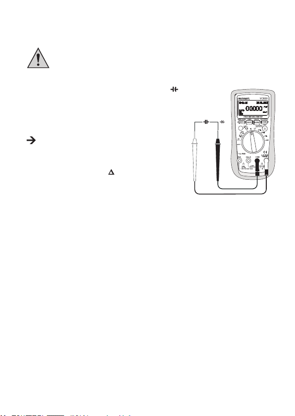
h) Measuring capacitance
Make sure that all circuit parts, switches and components, and other objects of
measurement are disconnected from the voltage and discharged at all times.
Always observe the polarity for electrolytic capacitors.
1. Turn on the DMM and select the measurement range “
2. Insert the red test lead in the °CHzVΩ measuring socket (7),
the black test lead in the COM measuring socket (8) (Fig. 8).
3. The unit “nF” will appear on the display.
Due to the sensitivity of the measuring input, it is possible
that a value is displayed when the test leads are “open”.
Pressing the REL/PC (Log/◄) button (10c) will set the
display to “0”. The base value (Rel difference) is displayed
next to the delta symbol
deactivated.
4. Now connect the two test prods (red = plus pole/black = minus
pole) with the object to be measured (capacitor). After a short
while the display shows the capacitance. Wait until the display
has stabilised. For capacitances >400 μF this may take a few
seconds.
5. If “OL” (for overload) appears on the display, you have exceeded the measuring range.
6. After the measurement has been completed, remove the test leads from the object being
measured and turn the DMM off.
. The autorange function is
”.
Fig. 8
64
Page 63

i) Measuring temperature
During the temperature measurement, expose only the temperature sensor to the
temperature to be measured. The operating temperature of the measuring device
must not be above or below the permissible range, because this can result in
measuring errors.
The contact temperature probe may only be used on voltage-free surfaces.
All K-type thermosensors can be used to measure temperature. The temperature is displayed in °C
and °F. The temperature probe included in delivery is designed for measurements between -40 to
+400 °C. Optional sensors can be used for the complete measuring range (-40 to +1000 °C).
For measuring temperatures, proceed as follows:
1. Turn on the DMM and select the measurement range “°C”.
2. Press the SHIFT/SETUP button (3) to switch to a display in °F.
3. Insert the thermosensor with the correct polarity with the plus
pole in the °CHzVΩ measuring socket (7) and the minus pole
in the COM measuring socket (8) (Fig. 9).
4. The temperature appears in the main display in °C or °F,
depending on the pressing of the SHIFT/SETUP button.
5. If “OL.” appears in the display, the measuring range (-40 to
+1000 °C) has been exceeded.
6. After the measurement has been completed, remove the
sensor and turn the DMM off.
When the measuring input (sockets: °CHzVΩ – COM) is bridged, the device temperature of
the DMM is displayed. The temperature adjustment to the environment is very slow due to the
sealed housing.
Fig. 9
65
Page 64

j) AC voltage measurement with 1 kHz low-pass lter
Never use the low-pass lter option to test for the presence of dangerous voltages!
The voltages present could be higher than indicated under some circumstances.
Always measure voltage without the lter rst to identify any dangerous voltages.
The DMM is equipped with an alternating current low-pass lter. This is an alternating current
measurement which is led through a low-pass lter in order to block unwanted voltages above 1 kHz.
Proceed as follows for AC voltage measurement with the
low-pass lter:
1. Turn on the DMM and select the measurement range
“ V
”. Press the SHIFT/SETUP button (3) to switch to the
measurement range “
2. Insert the red test lead in the °CHzVΩ measuring socket (7),
the black test lead in the COM measuring socket (8) (Fig. 10).
3. Connect the two test prods with the object to be measured
(generator, circuit, etc.). The measuring value is indicated on
the display.
4. After the measurement has been completed, remove the test
leads and turn the DMM off.
”.
Fig. 10
12. RANGE FUNCTION, MANUAL MEASURING RANGE
SELECTION
The RANGE function allows the manual selection of the measuring range in some functions with
automatic measuring range selection (AUTO). At the threshold areas, it is advisable to x the
measuring range in order to prevent unwanted switching.
Press the RANGE (-) button (10d) to switch to the manual measuring range selection. The indication
“AUTO” will go out in the display (if the manual measuring range selection is selected).
Set the desired measuring range by pressing the RANGE (-) button repeatedly.
To switch back to the automatic measuring range selection, hold down the RANGE (-) button for 2 s.
“AUTO” will again appear in the display (provided the autorange function is possible in this measuring
range).
66
Page 65

13. REL FUNCTION
The REL function allows a reference measurement to be made to avoid possible line losses such as
those occurring during resistance measurements. The currently displayed value is set to zero. A new
reference value has been set. The base value (Rel difference) is displayed next to the delta symbol .
This measuring function is activated by pressing the REL/PC (Log/◄) button (10c).
display. The automatic measuring range function is deactivated.
To switch off this function, press the REL/PC (Log/◄) button again or change the measuring function.
The REL function is not active in the measuring ranges temperature, continuity
test, diode test, frequency, and in the low-pass lter voltage measurement.
appears in the
14. HOLD FUNCTION
The HOLD function freezes the currently displayed measured value so that it can be read out or
logged.
When checking live conductors, ensure that this function is deactivated at the
start of the test. Otherwise, a false reading will result!
To turn on the hold function, press the H/LIGHT (+/COMP) button (10a); an acoustic signal conrms
this action and
To turn off the HOLD function, press the H/LIGHT (+/COMP) button again or change the measuring
function.
appears on the display.
15. MAX. / MIN. / AVG. FUNCTION
The MAX/MIN function allows the recording and display of the maximum and minimum values during a
measurement. After activation of the MAX/MIN function, the maximum or minimum value will be retained,
as required. The current measurement can still be seen in the upper area of the display (below the date).
The MAX function is switched on by pressing the MAX/MIN (View/►) button (10b). The maximum value
will be continuously retained in the main display. The symbol
Pressing the button again switches to the MIN function. The minimum value will be continuously
retained in the main display. This value is identied by the symbol
Pressing the button again switches to the AVG function. The average value will be continuously
retained in the main display. This value is identied by the symbol
appears in the display.
.
.
67
Page 66

To turn off this function, press the MAX/MIN (View/►) button for approx. 2 s.
The MAX/MIN function is not available in all measuring functions.
16. LOW IMP. 400 KΩ FUNCTION
This function may only be used for voltages of a max. of 1000 V and a max. of 3
seconds!
This function allows the reduction of the measuring impedance from 10 MΩ to 400 kΩ in the voltage
measuring range. Reducing the measuring impedance suppresses possible phantom voltages which
could falsify the measuring result.
Press the
release, the multimeter has the normal measuring impedance of 10 MΩ. While the button is pressed,
a signal sounds and appears on the display.
-button (9) during the voltage measurement (max. 1000 V!) for a max. 3 seconds. After
17. COMPARISON MODE (COMP MODE)
In the comparative measurement, once an upper and lower limit of the current measured parameter
is set, the main display will show only the actual status of the current measured value compared to
the preset range limit.
Proceed as follows to set the limit values for comparison mode:
1. Turn on the DMM and select the appropriate measurement range.
2. Insert the test leads into the correct measuring sockets.
3. Hold down the SHIFT/SETUP button (3) for approx. 2 s.
are now in SHIFT mode.
4. Hold down the SHIFT/SETUP button again for approx. 2 s to enter the SETUP menu.
5. To set the upper limit for the comparison mode, press the SHIFT/SETUP button until the menu
item “COMP MAX” is selected. An asterisk symbol * to the left of the menu item shows that the
menu item is selected.
6. You can now select the individual number of digits using the REL/PC (Log/◄) and MAX/MIN
(View/►) buttons and change their values with the H/LIGHT (+/COMP) or RANGE (-) button.
will appear on the display. You
68
Page 67

7. Once the setting has been made, press the SHIFT/SETUP button again to set the lower limit for the
comparison mode (menu item “COMP MIN”). Here, too, you can now select the individual decimal
places using the REL/PC (Log/◄) and MAX/MIN (View/►) buttons and change their values with
the H/LIGHT (+/COMP) or RANGE (-) button.
The limit settings do not have any units. The actual value of the limit results from the range set
in the measurement.
Example:
You have set the lower limit as “00900” and the upper limit as “01000” in the SETUP menu. In
a comparison measurement in the “mV
follows: “009.00 mV” (lower limit); “010.00 mV” (upper limit)
8. Now press the SHIFT/SETUP button to set the measurement status (menu item “COMP TYPE”).
9. Press the REL/PC (Log/◄) or MAX/MIN (View/►) buttons to select “OUTER” or “INNER”. When
“OUTER” is selected, the measured value is identied as passed (PASS) if it is outside the upper
and lower limits; when “INNER” is selected, the measured value is identied as passed (PASS) if
it is within the upper and lower limits.
10. Hold down the SHIFT/SETUP button (3) for approx. 2 sec to save the settings and exit the SETUP
menu. You will also exit SHIFT mode.
Performing a comparison measurement:
1. Select the measuring range.
2. Hold down the SHIFT/SETUP button (3) for approx. 2 s.
are now in SHIFT mode.
3. Now press the H/LIGHT (+/COMP) button (10a). The symbol
appear on the display.
The automatic measuring range selection is deactivated. Before beginning the
measurement, make sure that you have set the correct measuring range. You can
select this using the RANGE (-) button.
” measuring range, the values will be displayed as
will appear on the display. You
and the preset limits will
4. Connect the two test prods with the object to be measured.
5. The measured value is displayed with the appropriate units.
6. Depending on the previous setting the display will indicate if the currently measured value is within
or outside of the preset limits with the symbols
7. Press the H/LIGHT (+/COMP) button (10a) again to end the comparison mode.
(pass) and (did not pass).
69
Page 68

18. RECORDING AND MANAGING MEASURED VALUES
With its data logging function, the VC890 digital multimeter makes it possible to record up to 1000
measured values.
Proceed as follows to manually save measured values:
1. With the measuring device switched on, hold down the SHIFT/SETUP button (3) for approx. 2 s.
will appear on the display. You are now in SHIFT mode.
2. Now press the REL/PC (Log/◄) button (10c) to save the currently measured value.
appear on the display and below that the rst memory number “0001”.
3. To record another value, press the REL/PC (Log/◄) button again. The second memory number
“0002” is displayed.
4. To exit SHIFT mode, press the SHIFT/SETUP button.
If you have not stored any values for approx. 3 seconds, the symbol and the memory
number will go out. Press the REL/PC (Log/◄) button again to save more values. and
the memory number will appear on the display.
Saving measured values automatically:
1. First select the desired recording rate in the SETUP menu. The default setting of the device
records one measured value per second.
2. With the measuring device switched on, hold down the SHIFT/SETUP button (3) for approx. 2 s.
will appear on the display. You are now in SHIFT mode.
3. Hold down the SHIFT/SETUP button again for approx. 2 sec to open the SETUP menu.
4. Now press the SHIFT/SETUP button several times until the menu item “LOGGER SAMPLING
RATE” is selected. An asterisk symbol * to the left of the menu item shows that the menu item
is selected.
5. Press the H/LIGHT (+/COMP) or RANGE (-) button to set the recording rate (setting range: 1 to
10 seconds).
6. Hold down the SHIFT/SETUP button (3) for approx. 2 sec to save the setting and exit the SETUP
menu. You will also exit SHIFT mode.
7. To record measured values, you must switch to the SHIFT mode. With the measuring device
switched on, hold down the SHIFT/SETUP button (3) for approx. 2 sec until
the display.
8. Hold down the REL/PC (Log/◄) button for approx. 2 sec to start the automatic recording.
will appear on the display with the memory number below it. The device will now save the
measured values at the recording rate you have set.
9. To stop recording, hold down the REL/PC (Log/◄) button again for approx. 2 s.
will
appears on
70
Page 69

10. To continue recording, hold down the REL/PC (Log/◄) button again for approx. 2 s.
11. To exit the SHIFT mode, press the SHIFT/SETUP button.
Settings for the data memory:
1. Make the settings for the data memory in the SETUP menu.
2. With the measuring device switched on, hold down the SHIFT/SETUP button (3) for approx. 2 s.
will appear on the display. You are now in SHIFT mode.
3. Hold down the SHIFT/SETUP button again for approx. 2 sec to open the SETUP menu.
4. Now press the SHIFT/SETUP button several times until the menu item “LOGGER MEMORY” is
selected. An asterisk symbol * to the left of the menu item shows that the menu item is selected.
5. Press the REL/PC (Log/◄) or MAX/MIN (View/►) button to select “FIX” or “OVERWRITE”.
6. The setting “FIX” means that the measured values will be stored until the memory is full (max. 1000
measured values). The measurement will be stopped at the memory number “1000”.
7. The setting “OVERWRITE” means that the measured values will be continually stored. If the
measured value “1000” is reached, the device will begin to overwrite the measured values. The
memory number will no longer be displayed. Instead, a blinking innity symbol “∞” will appear.
8. The menu item “LOGGER MEMORY” is preset to “FIX” by default.
9. Hold down the SHIFT/SETUP button for approx. 2 sec to save the setting and exit the SETUP
menu. You will also exit SHIFT mode.
Display setting for automatic measured value recording:
1. In the automatic measurement, it is possible to activate the energy saving mode.
2. Make these settings in the SETUP menu.
3. With the measuring device switched on, hold down the SHIFT/SETUP button (3) for approx. 2 s.
will appear on the display. You are now in SHIFT mode.
4. Hold down the SHIFT/SETUP button again for approx. 2 sec to open the SETUP menu.
5. Now press the SHIFT/SETUP button several times until the menu item “LOGGER DATA DISPLAY”
is selected. An asterisk symbol * to the left of the menu item shows that the menu item is selected.
6. Press the REL/PC (Log/◄) or MAX/MIN (View/►) button to select “ON” or “OFF”.
7. The “ON” setting means that the display will always be switched on during the automatic
continuous measurement.
71
Page 70

8. The “OFF” setting turns the display off if the device is not operated for 5 minutes. Only the symbol
and the memory number are displayed. If the device is continually saving measured
values (“OVERWRITE” setting) and “1000” measured values are exceeded, a blinking innity
symbol “∞” is displayed below
9. By default, the device is set to “OFF”.
10. Hold down the SHIFT/SETUP button for approx. 2 sec to save the setting and exit the SETUP
menu. You will also exit SHIFT mode.
When the display is switched off in energy saving mode, turn the rotary switch or press any
button (apart from the -button (9)) to turn it back on.
Viewing saved measured values:
1. With the measuring device switched on, hold down the SHIFT/SETUP button (3) for approx. 2 s.
will appear on the display. You are now in SHIFT mode.
2. Now press the MAX/MIN (View/►) button (10b) to switch to the display mode.
on the display with the rst memory number “0001” below it. The saved measured value is shown
in the centre of the display.
3. Press the H/LIGHT (+/COMP) or RANGE (-) buttons to show the individual records.
4. Press the MAX/MIN (View/►) button again to exit the display mode.
5. Press the SHIFT/SETUP button to exit the SHIFT mode.
The stored measured values of a comparison measurement are shown in the display with the
symbols and .
If “VOID” appears in the display, that means that the measured value memory is empty.
Deleting saved measured values:
1. With the measuring device switched on, hold down the SHIFT/SETUP button (3) for approx. 2 s.
will appear on the display. You are now in SHIFT mode.
2. Hold down the MAX/MIN (View/►) button (10b) for approx. 2 s. The indication
will briey appear on the display. All measured values are deleted.
3. Press the SHIFT/SETUP button to exit the SHIFT mode.
.
will appear
and “VOID”
72
Page 71

19. AUTO POWER OFF FUNCTION
1. The DMM will switch off automatically after a specied time if no button is pressed or the rotary
switch is not turned. This function protects and conserves the battery and extends the operating
time.
2. You can set a switch-off time in the SETUP menu. The default setting on the device is 5 minutes.
3. With the measuring device switched on, hold down the SHIFT/SETUP button (3) for approx. 2 s.
will appear on the display. You are now in SHIFT mode.
4. Hold down the SHIFT/SETUP button again for approx. 2 sec to open the SETUP menu.
5. Now press the SHIFT/SETUP button several times until the menu item “APO TIME” is selected. An
asterisk symbol * to the left of the menu item shows that the menu item is selected.
6. Press the REL/PC (Log/◄) and MAX/MIN (View/►) buttons to set the switch-off time. The
choices are 5 MIN, 15 MIN, 30 MIN, or OFF. The “OFF” setting means that the auto power off
function is deactivated.
7. Hold down the SHIFT/SETUP button for approx. 2 sec to save the setting and exit the SETUP
menu. You will also exit SHIFT mode.
8. If you have set a switch-off time, the symbol
To switch the DMM back on after an automatic switch-off turn the rotary switch or press any
button (apart from the -button (9)).
The auto power off function is deactivated when data is transmitted to a PC so as not to
interrupt the data connection. The auto power off function is inactive until the data transmission
to a PC (via optical interface) is switched off again.
The auto power off function is also deactivated during automatic recording of measured values.
will appear on the display.
20. OPTICAL INTERFACE
An optically insulated interface (11) is integrated into the back of the measuring device for transferring
the measurement data to a computer where they can be further processed.
The data connection can be made with a free USB interface on your computer using the supplied USB
interface adaptor (the software “Voltsoft” must already be installed on the computer).
Push the interface cover up from the housing. Insert the wedge-shaped adaptor from above into and
ush with the housing slot on the measuring device.
Then insert the type A USB plug on the other end of the interface cable into a free USB port on the
computer.
73
Page 72

The interface is switched off during normal operation. To activate it, hold down the REL/PC (Log/◄)
button (10c) for 2 sec with the device switched on. The activation is indicated by the interface symbol
. To deactivate it, hold down the REL/PC (Log/◄) button for approx. 2 sec or turn off the DMM.
21. SOFTWARE INSTALLATION
1. Insert the CD into the CD-ROM of your computer.
2. The installation will start automatically. If not, please go to your CD-ROM directory, and open the
installation le “autorun.exe”.
3. Select your desired language from German, English and French.
4. Follow the instructions on the dialog box, select the destination for the installation and complete
the installation.
5. For further information, please refer to the operating instructions on the CD provided.
6. The enclosed software is the Voltsoft standard edition. The professional version (Voltsoft PRO, No.
10 13 33) is an optional item which you can purchase separately. If you purchase the professional
version, you will get the license key. Follow the steps in the Voltsoft user manual, to register and
upgrade your software to the professional version.
7. Voltsoft software updates to the latest version of the Voltsoft program are available when the
program is running and the Internet is connected; or check for the latest Voltsoft update via
“http://www.conrad.com”
22. DISPLAY BRIGHTNESS
1. The brightness of the display can be set in steps. Hold down the H/LIGHT (+/COMP) button (10a)
for approx. 2 sec to switch between the three brightness steps.
2. You can activate or deactivate the energy saving mode for the display in the SETUP menu. The
energy saving mode is active on the device by default.
3. If the energy saving mode is switched on, the display brightness will be automatically reduced
during inactivity. If the device is not operated for 15 seconds, the display brightness will switch from
the highest brightness level to the middle level. After another 15 seconds of inactivity the display
will switch from the middle level to the lowest level.
4. With the measuring device switched on, hold down the SHIFT/SETUP button (3) for approx. 2 s.
will appear on the display. You are now in SHIFT mode.
5. Hold down the SHIFT/SETUP button again for approx. 2 sec to open the SETUP menu.
74
Page 73
6. Now press the SHIFT/SETUP button several times until the menu item “AUTO BRIGHTNESS” is
selected. An asterisk symbol * to the left of the menu item shows that the menu item is selected.
7. Press the REL/PC (Log/◄) or MAX/MIN (View/►) button to select “ON” or “OFF”.
8. The “ON” setting means that the energy saving mode is activated. The brightness of the display
will be automatically reduced during inactivity.
9. The “OFF” setting switches off the energy saving mode.
10. Hold down the SHIFT/SETUP button for approx. 2 sec to save the setting and exit the SETUP
menu. You will also exit SHIFT mode.
23. MAINTENANCE AND CLEANING
a) General
Calibrate the multimeter annually to guarantee the accuracy of the multimeter over a longer period
of time.
The measuring device is absolutely maintenance-free except for occasional cleaning and the
replacement of fuses.
You can nd the fuse and battery replacement instructions below.
Regularly check the technical safety of the device and the test leads, for example
damage to the housing, pinching of the test leads, etc.
b) Cleaning
Always observe the following safety instructions before cleaning the device:
Live components may be exposed when covers are opened or components are
removed, except if this can be done by hand.
The connected lines must be disconnected from the measuring device and all
measuring objects prior to cleaning or repairing the device. Turn off the DMM.
Do not use cleaning agents which contain carbon, petrol, alcohol or similar substances for cleaning
purposes. These could corrode the surface of the measuring device. Furthermore, the fumes are
hazardous to your health and explosive. You should also not use sharp-edged tools, screwdrivers, or
metal brushes or similar for cleaning.
75
Page 74

Use a clean, lint-free, antistatic and slightly damp cloth to clean the device and display. Allow the
device to dry completely before using it for the next measuring task.
c) Opening the measuring device
For reasons of safety, it is only possible to replace the fuse and battery when all test leads have been
removed from the measuring device. The battery and fuse compartment cannot be opened when test
leads are plugged in.
In addition, when the housing is opened all measuring sockets are mechanically locked in order to
prevent the later insertion of the test leads. The locking will be automatically removed when the battery
and fuse compartment is again closed.
The housing is designed so that when the battery and fuse compartment is open only the battery
and fuses can be accessed. The housing does not have to be opened completely or taken apart any
longer. These measures increase the user safety and user-friendliness.
Proceed as follows to open:
1. Remove all test leads from the measuring device and switch
it off.
2. Loosen and remove the battery compartment screw (15) on
the back.
3. Fold out the positioning bracket (13). Pull the battery and
fuse compartment lid downwards from the measuring device
(Fig. 11).
4. The fuses and battery compartment are now accessible.
5. Close the housing in the reverse order and screw closed the
battery and fuse compartment.
6. The measuring device is again ready for use.
Fig. 11
76
Page 75

d) Fuse check/fuse replacement
The current measuring ranges are protected with high breaking capacity fuses. If no measurement is
possible in this range, the fuse must be replaced.
The measuring device allows the testing of fuses with the housing closed.
Proceed as follows to test:
1. On the rotary switch, select the measuring range “Ω”.
2. Insert a test lead in the °CHzVΩ socket (7).
3. Contact the current measuring socket to be tested with the
test prod (Fig. 12).
4. If a measured value is displayed, the fuse is okay. However,
if the display reads “OL”, the corresponding fuse is defective
and must be replaced.
Proceed as follows to replace the fuse:
1. Remove the attached test leads from the measuring circuit and from your measuring device. Turn
off the DMM.
2. Open the housing as described in Section “c) Opening the measuring device” (page 76).
3. Replace the defective fuse with a new one of the same type and current rating or similar. The fuses
have the following values:
Fuse F1 F2
Nominal data F600mA H 1000V F10A H 1000V
Breaking capacity 30 kA
Dimension (ø x L) 6.35 x 31.8 mm 10.3 x 38 mm
Item no. 44 24 03 44 23 35
4. Close the housing again carefully.
For reasons of safety, the use of repaired fuses or the bridging of the fuse holder
is not permitted. This can lead to re or electric arc explosion. Do not use the
measuring device in this state under any circumstances.
Fig. 12
77
Page 76

e) Replacing the button cell battery
If the date and time are no longer correctly displayed, the button cell battery must be replaced.
Proceed as follows to replace the button cell battery:
1. Remove the attached test leads from the measuring circuit and from your measuring device. Turn
off the DMM.
2. Open the battery and fuse compartment as described in Section “c) Opening the measuring de-
vice” (page 76).
3. Then loosen the four screws on the back of the device and carefully remove the housing.
4. Carefully push the button cell battery out of the battery holder from below. Lift the battery holder
slightly upwards while doing so.
5. Replace the used button cell battery with a new one of the same type (CR2032). Insert a new
button cell battery into the battery compartment. Make sure that the plus pole points upwards.
6. Close the housing in the reverse order and screw closed the battery and fuse compartment.
You can order a suitable button cell battery using the following part number:
Item no. 650183
78
Page 77
24. DISPOSAL
a) Product
Electronic devices are recyclable waste and must not be disposed of in the household
waste.
At the end of its service life, dispose of the product according to the relevant statutory
regulations.
Remove any inserted (rechargeable) batteries and dispose of them separately from the
product.
b) Batteries / Rechargeable batteries
You as the end user are required by law (Battery Ordinance) to return all used batteries/rechargeable
batteries. Disposing of them in the household waste is prohibited.
Contaminated (rechargeable) batteries are labelled with this symbol to indicate that
disposal in the domestic waste is forbidden. The designations for the heavy metals
involved are: Cd = Cadmium, Hg = Mercury, Pb = Lead (name on (rechargeable) batteries,
e.g. below the trash icon on the left).
Used (rechargeable) batteries can be returned to collection points in your municipality, our
stores or wherever (rechargeable) batteries are sold.
You thus full your statutory obligations and contribute to the protection of the environment.
25. TROUBLESHOOTING
The DMM you have purchased is equipped with state-of-the-art technology and is safe to operate.
Nevertheless, problems and faults might occur.
We would therefore like to explain some of the ways you can simply eliminate possible faults:
Always observe the safety instructions!
79
Page 78

Error Possible cause Possible solution
The multimeter does not
work.
The measuring value does
not change.
The measuring device
beeps and one of
the following warning
messages is displayed:
ERROR ON V INPUT
ERROR ON A INPUT
ERROR ON mA INPUT
Repairs other than those just described should only be performed by an authorised
specialist.
Is the battery at? Check the condition.
Replace the battery.
Is the wrong measuring
function active (AC/DC)?
Are the test leads rmly
inserted into the measuring
sockets?
Is the fuse defective? Check the fuses.
Is the hold function activated?
)
(display
Incorrectly attached or
improper test leads.
Check the display (AC/DC)
and change the function if
necessary.
Check the seating of the test
leads.
Press the H/LIGHT (+/COMP)
button to deactivate this
function.
Connect the test leads properly
to the measuring device,
exchange them, or change the
measuring function.
80
Page 79

26. TECHNICAL DATA
Display .................................Max. 60000 counts (characters)
Measuring rate .....................
Measuring line length ..........approx. 90 cm each
Measuring impedance .........>10 MΩ (V range)
Operating voltage ................9 V block battery
Working conditions ..............0 to +30 ºC (<75 % RH), +30 to +40 ºC (<50 % RH)
Operating altitude ................max. 2000 m
Storage temperature ............-10 to +50 ºC
Weight .................................approx. 380 g
Dimensions (L x W x H) .......185 x 91 x 43 mm
Over-voltage category .........CAT III 1000 V, CAT IV 600 V, contamination degree 2
Measurement tolerances
Statement of accuracy in ± (% of reading + display error in counts (= number of smallest points)). The
accuracy is valid for one year at a temperature of +23 °C (± 5 °C), and at a relative humidity of less
than 75 %, non-condensing. Temperature coefcient: +0.1 x (specied accuracy)/1 °C
Direct voltage
Range Accuracy Resolution
600 mV ±(0,03 % + 10 digits) 0.01 mV
6 V
60 V 0.001 V
600 V 0.01 V
1000 V 0.1 V
Overload protection: 1000 V; Impedance: 10 MΩ
approx. 2 – 3 measurements/second,
Bargraph: approx. 2 – 3 measurements/second
0.0001 V
±(0,05 % + 10 digits)
81
Page 80

Alternating voltage
Range Resolution Accuracy Frequency range
6 V 0.0001 V
60 V 0.001 V
600 V 0.01 V
1000 V 0.1 V
Overload protection: 1000 V; Impedance: approx. 10 MΩ
TrueRMS in the measuring range of 10 – 100 %; Crest factor: max. 3.0 (at 1000 V max. 1.5)
Measuring function AC + DC voltage
Range Resolution Accuracy Frequency range
6 V 0.0001 V
60 V 0.001 V
600 V 0.01 V
1000 V 0.1 V
Overload protection: 1000 V; Impedance: 10 MΩ
±(0.5 % + 40 digits) 45 Hz – 1 kHz
±(1.2 % + 40 digits) 1 kHz - 10 kHz
±(3 % + 40 digits) 10 kHz - 20 kHz
±(4 % + 40 digits) 20 kHz - 100 kHz
±(0.5 % + 40 digits) 45 Hz - 1kHz
±(1.2 % + 40 digits) 1 kHz - 10 kHz
±(3 % + 40 digits) 10 kHz - 20 kHz
±(6 % + 40 digits) 20 kHz - 100 kHz
±(0.5 % + 40 digits) 45 Hz - 1kHz
±(1.2 % + 40 digits) 1 kHz - 10 kHz
±(3 % + 40 digits) 10 kHz - 20 kHz
Not specied 20 kHz - 100 kHz
±(1.2 % + 40 digits) 45 Hz - 1kHz
±(3 % + 40 digits) 1 kHz - 5 kHz
±(6 % + 40 digits) 5 kHz - 10 kHz
Not specied 10 kHz - 100 kHz
±(1 % + 80 digits) 45 Hz - 1 kHz
±(3 % + 40 digits) 1 kHz - 10 kHz
±(6 % + 40 digits) 10 kHz - 35 kHz
±(1 % + 80 digits) 45 Hz - 1 kHz
±(3% + 40 digits) 1 kHz - 10 kHz
±(6 % + 40 digits) 10 kHz - 35 kHz
±(1 % + 80 digits) 45 Hz - 1 kHz
Not specied 1 kHz - 10 kHz
Not specied 10 kHz - 35 kHz
±(1.2 % + 80 digits) 45 Hz - 1 kHz
Not specied 1 kHz - 10 kHz
Not specied 10 kHz - 35 kHz
82
Page 81

Direct current
Range Accuracy Resolution
600 μA ±(0.3 % + 10 digits) 0.01 μA
6000 μA
60 mA 0.001 mA
600mA 0.01 mA
10 A ±(1.5 % + 20 digits) 0.001 A
Overload protection: Fuses; measuring time limit >5 A: max. 10 s with 10 min break
Alternating current
Range Resolution Accuracy Frequency range
600 µA 0.01 μA
6000 μA 0.1 μA
60 mA 0.001 mA
600 mA 0.01 mA
10 A 0.001 A
Overload protection: Fuses; measuring time limit >5 A: max. 10 s with 10 min break;
Overload protection: 1000 V; TrueRMS in the measuring range of 10 – 100 %
Impedance
Range Accuracy Resolution
600 Ω ±(1.0 % + 10 digits) with REL function 0.01 Ω
6 kΩ
60 kΩ 0.001 kΩ
600 kΩ 0.01 kΩ
6 MΩ ±(1.2 % + 10 digits) 0.0001 MΩ
60 MΩ ±(2 % + 5 digits) 0.001 MΩ
Overload protection: 1000 V
±(0.6 % + 10 digits)
±(0.5 % + 10 digits)
±(0.6 % + 40 digits) 45 Hz - 1 kHz
±(1.2 % + 40 digits) 1 kHz - 10 kHz
±(0.6 % + 40 digits) 45 Hz - 1 kHz
±(1.2 % + 40 digits) 1 kHz - 10 kHz
±(0.6 % + 40 digits) 45 Hz - 1 kHz
±(1.2 % + 40 digits) 1 kHz - 10 kHz
±(0.6 % + 40 digits) 45 Hz - 1 kHz
±(1.2 % + 40 digits) 1 kHz - 10 kHz
±(2 % + 40 digits)
±(4 % + 40 digits) 1 kHz - 10 kHz
0.1 μA
45 Hz - 1 kHz
0.0001 kΩ
83
Page 82

Capacity
Range Accuracy Resolution
60 nF ±(2.5 % + 20 digits) 0.001 nF
600 nF
6 μF 0.0001 μF
60 μF 0.001 μF
600 μF 0.01 μF
6000 μF ±(5 % + 20 digits) 0.1 μF
60 mF Not specied 0.001 mF
Overload protection: 1000 V
Frequency
Range Accuracy Resolution
60 Hz
600 Hz 0.01 Hz
6 kHz 0.0001 kHz
60 kHz 0.001 kHz
600 kHz 0.01 kHz
6 MHz 0.0001 MHz
60 MHz 0.001 MHz
Overload protection: 1000 V;
For 10 Hz – 60 MHz, input amplitude a: 1 Vrms ≤ a ≤ 30 Vrms
Duty-Cycle (pulse-break ratio)
Range Accuracy Resolution
10 Hz – 2 kHz
(10 % – 90 %)
Overload protection: 1000 V
±(2.0 % + 20 digits)
±(0.02 % + 8 digits)
±(1.2 % + 30 digits)
0.01 nF
0.001 Hz
0.01 %
84
Page 83

Temperature
Range Accuracy Resolution
-40 to +40 ºC ±(3 % + 20 digits)
0.1 ºC+40 to +400 ºC ±(2 % + 20 digits)
+400 to +1000 ºC ± 2.5 %
-40 to +32 ºF ±(2.5 % + 40 digits)
0.2 ºF+32 to +752 ºF ±(1.5 % + 40 digits)
+752 to +1832 ºF ± 2.5 %
Overload protection: 1000 V
Diode test
Test voltage Resolution
3.1 V 0.0001 V
Overload protection: 1000 V
Acoustic continuity tester
Resolution: 0.01 Ω
Overload protection: 1000 V, <10 Ω continuous sound
Low-pass lter test
Range Resolution Remark
6 V 0.0001 V Filter AC voltage signal higher than 1 kHz.
60 V 0.001 V
600 V 0.01 V
1000 V 0.1 V
85
Page 84

TABLE DES MATIÈRES
Page
1. Introduction ................................................................................................................................. 87
2. Utilisation conforme ...................................................................................................................... 88
3. Éléments de commande .............................................................................................................. 89
4. Explication des symboles ............................................................................................................. 91
5. Consignes de sécurité .................................................................................................................. 92
6. Description du produit .................................................................................................................. 95
7. Contenu de la livraison ................................................................................................................. 95
8. Indications apparaissant à l’écran et symboles ............................................................................ 96
9. Pile ............................................................................................................................................... 97
10. Régler la date et l’heure ............................................................................................................... 98
11. Mode de mesure .......................................................................................................................... 99
12. Fonction RANGE, sélection manuelle de la plage de mesure ................................................... 107
13. Fonction REL .............................................................................................................................. 108
14. Fonction Hold ............................................................................................................................. 108
15. Fonction MAX. / MIN. / AVG. ...................................................................................................... 108
16. Fonction Low Imp 400 KΩ ......................................................................................................... 109
17. Mode de comparaison (Comp-Mode) ........................................................................................ 109
18. Enregistrement et gestion des valeurs mesurées ....................................................................... 111
19. Fonction d’extinction automatique (Auto-Power-OFF) ................................................................11 4
20. Interface optique .........................................................................................................................11 4
21. Installation du logiciel ..................................................................................................................11 5
22. Luminosité de l´écran ..................................................................................................................11 5
23. Entretien et nettoyage .................................................................................................................11 6
24. Elimination des déchets ............................................................................................................. 120
25. Dépannage ................................................................................................................................. 120
26. Caractéristiques techniques ....................................................................................................... 122
86
Page 85

1. INTRODUCTION
Chère cliente, cher client,
En choisissant un produit Voltcraft®, vous avez choisi un produit d’une qualité exceptionnelle, ce dont
nous vous remercions vivement.
Voltcraft® - Ce nom est en effet garant d’une qualité au dessus de la moyenne dans les domaines de
la mesure, de la recharge ainsi que des appareils de réseau, tous se distinguant par leur compétence
technique, leur abilité, leur longévité et une innovation permanente.
Que vous soyez des électroniciens amateurs ambitionnés ou des utilisateurs professionnels, vous
trouverez dans les produits de la famille Voltcraft® des appareils vous mettant à disposition la solution
optimale pour les tâches les plus exigeantes. Et notre particularité : Nous pouvons vous offrir la
technique éprouvée et la qualité able des produits Voltcraft® à des prix imbattables du point de
vue rapport qualité/prix. Ainsi, nous mettons à votre disposition des produits aptes à satisfaire vos
exigences les plus pointues.
Nous vous souhaitons beaucoup de plaisir avec votre nouvel appareil Voltcraft® !
Tous les noms de société et toutes les désignations de produit sont des marques déposées de
leurs propriétaires respectifs. Tous droits réservés.
Pour toute question technique, veuillez vous adresser à:
France (email): technique@conrad-france.fr
Suisse: www.conrad.ch
www.biz-conrad.ch
87
Page 86

2. UTILISATION CONFORME
• Mesure et afchage des grandeurs électriques dans la catégorie de surtension CAT IV jusqu´à
600 V maximum ou CAT III jusqu‘à 1000 V maximum contre le potentiel terrestre, selon la norme
EN 61010-1 et toutes les catégories moins élevées.
• Mesure de la tension continue et alternative de 1000 V max.
• Mesure du courant continu et alternatif de 10 A max.
• Mesure de la fréquence jusqu‘à 60 Mhz
• Mesure des capacités jusqu‘à 60 mF
• Mesure des résistances jusqu’à 60 MΩ
• Contrôle de continuité (<10 Ω, acoustique)
• Test de diodes
• Mesure de la température de -40 à +1000 ºC
• Afchage du rapport de signal (Duty-Cycle) en % (10 – 90 %)
• 1 kHz Mesure de tension alternative du ltre passe-bas
• Mesure de valeur comparative
• Mémoire des données de mesure et enregistreur de données pour 1000 valeurs avec horodatage
• Transfert des données au PC par interface optique
• Afchage de la date et de l‘heure
Un commutateur rotatif permet de sélectionner les fonctions de mesure. La sélection de la plage de
mesure s‘effectue dans toutes les fonctions (à l‘exception du test de diode et de continuité). À tout
moment, il est possible d‘effectuer un réglage manuel.
Le VC890 afche les valeurs mesurées effectives et vraies (True RMS) à la fois dans la plage de
mesure en tension continue ainsi qu‘en tension alternative et du courant.
En cas de valeur mesurée négative, la polarité est représentée automatiquement avec le signe (-).
Les deux entrées de mesure du courant sont protégées contre les surcharges par des fusibles
céramiques HPC.
La tension dans le circuit de mesure du courant ne doit pas dépasser 1000 V en CAT III ou 600 V
en CAT IV.
Une fonction de faible impédance (Low Imp) permet de mesurer avec une résistance interne réduite.
Celle-ci supprime les tensions fantômes qui peuvent survenir dans les mesures de haute valeur. La
mesure avec une impédance réduite n‘est autorisée que dans les circuits de mesure jusqu‘à 1000 V
max. pour seulement 3 s. max. Lors de l‘actionnement de la touche Low Imp, un signal sonore retentit
et un message d‘avertissement s‘afche à l‘écran.
Le multimètre est alimenté par une pile monobloc alcaline 9V ou au lithium usuelle. La mise en service
est uniquement autorisée avec la pile spéciée. Une fonction d’extinction automatique empêche
l‘épuisement prématurée de la pile lorsque l‘appareil n‘est pas utilisé pendant un certain temps
88
Page 87

(réglages : 5 min., 15 min., 30 min. ou OFF (arrêt), cf. chapitre «19. Fonction d’extinction automatique
(Auto-Power-OFF)». Pendant le transfert des données sur le PC via une interface optique, la fonction
d’extinction automatique est désactivée.
Le multimètre ne doit pas être utilisé lorsque celui-ci ou le logement de la pile est ouvert ou que le
couvercle du logement de la pile est absent. Le dispositif de protection ne permet pas d‘ouvrir le
couvercle de la pile et du fusible, lorsque les cordons de mesure sont connectés aux douilles. Cela
empêche aussi l‘insertion de cordons de mesure lorsque le couvercle de la pile et du fusible est
ouvert.
Les mesures ne doivent pas s‘effectuer dans des locaux humides ou dans des conditions ambiantes
défavorables. Des conditions ambiantes défavorables sont : l’humidité ou l’humidité atmosphérique
trop élevée, les poussières et le gaz, les vapeurs ou les solvants inammables, ainsi que les orages
ou les conditions orageuses telles que des champs électrostatiques intenses, etc.
Pour effectuer les mesures, utilisez exclusivement les câbles ou accessoires de mesure conformes
aux spécications du multimètre.
Pour des raisons de sécurité et d’homologation (CE), toute transformation et/ou modication du
produit est interdite. Si vous utilisez le produit à d’autres ns que celles décrites précédemment, cela
risque d’endommager le produit. Par ailleurs, une utilisation incorrecte peut être source de dangers
tels que court-circuit, incendie, électrocution. Lisez attentivement le mode d’emploi et conservez le.
Ne transmettez le produit à des tiers qu’accompagné de son mode d’emploi.
Respectez toutes les consignes de sécurité et les informations du présent mode
d‘emploi.
3. ÉLÉMENTS DE COMMANDE
Voir le volet rabattable.
1 Cadre de protection en caoutchouc
2 Écran
3 Touche SHIFT/SETUP
Commutation de la fonction de mesure (symboles rouges sur le commutateur rotatif) /
Commutation de fonction des touches (touches marquées en bleu)
4 Commutateur rotatif pour sélectionner la fonction de mesure
5 Douille de mesure mAμA
6 Douille de mesure 10 A
7 Douille de mesure °CHzVΩ (pour un « positif » de même niveau)
8 Douille de mesure COM (potentiel de référence, « négatif »)
9 Touche
Touche Low Imp. 400 kΩ pour la commutation de l’impédance
89
Page 88

10 Touches de fonction :
a Touche H/LIGHT (+/COMP) :
« H » = fonction Hold pour geler l’écran de mesure
« LIGHT » = régler la luminosité de l’écran
« + » = augmenter la valeur
« COMP » = mode de comparaison
b Touche MAX/MIN (View/►) :
« MAX/MIN » = pour enregistrer et afcher les valeurs max. et min.
« View » = afcher les valeurs enregistrées
« ► » = navigation dans le menu SETUP
c Touche REL/PC (Log/◄) :
« REL » = mesure de la valeur de référence
« PC » = transfert des données au PC par une interface optique
« Log » = enregistrer les valeurs
« ◄ » = navigation dans le menu SETUP
d Touche RANGE (-) :
« RANGE » = commutation manuelle de la plage de mesure
« - » = diminuer la valeur
11 Interface isolée optiquement
12 Filet de raccord statif
13 Béquille escamotable
14 Logement de la pile
15 Vis pour le logement de la pile et du fusible
16 Logement du fusible
90
Page 89

4. EXPLICATION DES SYMBOLES
Dans le présent mode d’emploi, un point d’exclamation placé dans un triangle signale les
remarques importantes à impérativement respecter.
Le symbole de l’éclair dans un triangle met en garde contre tout risque de décharge
électrique ou toute atteinte à la sécurité électrique de l’appareil.
Le symbole de « èche » précède les recommandations et consignes d’utilisation
particulières.
Cet appareil est homologué CE et satisfait aux directives européennes en vigueur.
Classe de protection 2 (double isolation ou isolation renforcée)
Catégorie de surtension II pour les mesures réalisées sur les appareils électriques et
électroniques qui sont alimentés en tension par une che secteur. Cette catégorie
CAT II
comprend également toutes les catégories inférieures (telles que CAT I pour la mesure
des tensions du signal et des tensions de commande).
Catégorie de surtension III pour les mesures réalisées lors des installations à l’intérieur
de bâtiments (par ex. prises de courant ou répartitions secondaires). Cette catégorie
CAT III
comprend également toutes les catégories inférieures (par ex. CAT II pour les mesures
réalisées sur les appareils électriques).
Catégorie de surtension IV pour les mesures effectuées à la source de l’installation
basse tension (par ex. distributeur principal, point d’interconnexion des entreprises
CAT IV
d’approvisionnement en électricité, etc.). Cette catégorie comprend également toutes les
catégories inférieures.
Potentiel terrestre
91
Page 90

5. CONSIGNES DE SÉCURITÉ
Lisez le mode d’emploi avec attention en étant particulièrement attentif aux
consignes de sécurité. En cas de non-respect des consignes de sécurité et des
informations données dans le présent mode d’emploi pour une utilisation correcte
de l’appareil, nous déclinons toute responsabilité en cas de dommage personnel ou
matériel consécutif. En outre, la responsabilité/garantie sera alors annulée.
a) Personnes / Produit
• Ce produit n’est pas un jouet. Gardez-le hors de portée des enfants et des animaux
domestiques.
• Ne laissez pas traîner le matériel d’emballage. Cela pourrait devenir un jouet pour
enfants très dangereux.
• Gardez le produit à l’abri de températures extrêmes, de la lumière du soleil directe,
de secousses intenses, d’humidité élevée, d’eau, de gaz inammables, de vapeurs
et de solvants.
• N’exposez pas le produit à des contraintes mécaniques.
• Si une utilisation en toute sécurité n’est plus possible, cessez d’utiliser le produit et
protégez-le d’une utilisation accidentelle. Une utilisation en toute sécurité n’est plus
garantie si le produit :
- présente des traces de dommages visibles,
- le produit ne fonctionne plus comme il devrait,
- a été stocké pour une période prolongée dans des conditions défavorables ou bien
- a été transporté dans des conditions très rudes.
• Maniez le produit avec précaution. À la suite de chocs, de coups ou de chutes, même
de faible hauteur, l’appareil peut être endommagé.
• Respecter également les informations concernant la sécurité et le mode d’emploi pour
les autres appareils connectés à cet appareil.
• Pour des raisons de sécurité et d’homologation (CE), il est interdit de transformer et/ou
modier l’appareil de manière arbitraire.
• Veuillez consulter un spécialiste si vous avez des doutes sur la manière dont fonctionne
le produit ou si vous avez des questions liées à la sécurité ou au raccordement de
l’appareil.
• Dans les installations industrielles, il convient d’observer les directives en matière
de prévention des accidents relatives aux installations et aux matériels électriques
dénies par les associations professionnelles.
92
Page 91

• Dans les écoles, les centres de formation, les ateliers de loisirs et de réinsertion,
la manipulation d’appareils de mesure doit être surveillée par des personnes
spécialement formées à cet effet.
• Avant de mesurer la tension, assurez-vous que l’appareil de mesure ne se trouve pas
dans la plage de mesure du courant.
• La tension entre les points de connexion de l’appareil de mesure et le potentiel
terrestre ne doit pas dépasser 1 000 V CC/CA dans la CAT III et 600 V dans la CAT IV.
• Éloignez les pointes de mesure de l’objet à mesurer avant de changer de plage de
mesure.
• Une prudence particulière est conseillée en présence de tensions alternatives (CA)
supérieures à 25 V ou de tensions continues (CC) supérieures à 35 V ! En cas de
contact avec les conducteurs électriques, de telles tensions peuvent provoquer une
électrocution comportant un danger de mort.
• Avant chaque mesure, assurez-vous que ni votre appareil de mesure ni les câbles ne
soient endommagés.
• N’effectuez jamais de mesures dans le cas où l’isolation de protection serait
endommagée (déchirée, arrachée, etc.).
• An d’éviter une électrocution, veillez, pendant la mesure, à ne pas toucher directement
ou indirectement les raccordements/points de mesure.
• Ne pas saisir les marquages tactiles de la zone de préhension des pointes de mesure
pendant la mesure.
• N’utilisez pas le multimètre juste avant, pendant ou juste après un orage (coup de
foudre ! / surtensions à haute énergie !). Veillez impérativement à ce que vos mains,
vos chaussures, vos vêtements, le sol, les circuits et les éléments du circuit, etc. soient
parfaitement secs.
• Évitez de faire fonctionner l’appareil à proximité immédiate des éléments suivants :
- champs électromagnétiques ou magnétiques à forte intensité
- antennes émettrices ou générateurs HF.
La valeur mesurée risquerait d’être ainsi faussée.
• N’allumez jamais l’appareil de mesure immédiatement après l’avoir transporté d’un
local froid dans un local chaud. L’eau de condensation qui se forme alors risquerait
de détruire l’appareil.
• Attendez que l’appareil non branché ait atteint la température ambiante.
• Observez également les consignes de sécurité gurant dans les différents chapitres.
93
Page 92

b) Piles / Accumulateurs
• Attention à bien respecter la polarité lors de la mise en place des piles. (« + » = positif,
« – » = négatif).
• Retirer les piles de l’appareil lorsque ce dernier n’est pas utilisé pendant une longue
durée an d’éviter tout endommagement dû à des fuites. Des fuites ou des piles
endommagées peuvent provoquer des brûlures acides lors d’un contact avec la peau,
il convient donc d’utiliser des gants de protection appropriés pour manipuler des piles
usagées.
• Maintenir les piles hors de portée des enfants. Ne pas laisser de pile traîner, un enfant
ou un animal domestique pourrait en avaler une.
• Ne pas démonter, court-circuiter ou jeter des piles dans le feu. Ne jamais recharger des
piles non rechargeables. Un risque d’explosion existe.
c) Divers
• Adressez-vous à un technicien spécialisé si vous avez des doutes concernant le mode
de fonctionnement, la sécurité ou le raccordement de l‘appareil.
• Tout entretien, ajustement ou réparation ne doit être effectué que par un spécialiste
ou un atelier spécialisé.
En cas de doute quant au raccordement correct de l’appareil, de son utilisation ou lorsque vous
avez des questions pour lesquelles vous ne trouvez aucune réponse dans le présent mode d’emploi,
contactez notre service de renseignements techniques ou un autre spécialiste.
94
Page 93

6. DESCRIPTION DU PRODUIT
Les valeurs mesurées s’afchent sur un écran numérique du multimètre (désigné ci-après DMM).
L’afchage des valeurs mesurées du DMM comprend 60 000 counts (count = la plus petite valeur
qui peut être afchée).
En cas de non-utilisation de l’appareil (réglages : 5 min., 15 min., 30 min.), il s’éteint automatiquement.
La pile est ménagée et gagne en durée de vie. Pendant le transfert des données au PC via une
interface optique, cette fonction est désactivée.
L’appareil de mesure est destiné tant à un usage amateur que professionnel jusqu’à CAT IV.
Pour une meilleure lisibilité, le DMM peut être placé de manière idéale grâce à la béquille escamotable
arrière.
Le logement de la pile et du fusible ne peut être ouvert que lorsque tous les cordons de mesure ont
été retirés de l’appareil. Si le logement de la pile et du fusible est ouvert, il n’est pas possible d’insérer
les cordons de mesure dans les douilles de mesure. Cela augmente la sécurité pour l’utilisateur.
Dans la plage de mesure de la tension et du courant, un signal d’avertissement et des messages
à l’écran surviennent si les cordons de mesure ont été mal connectés. Connectez les cordons de
mesure correctement avant de mesurer.
Commutateur rotatif (4)
Un commutateur rotatif permet de sélectionner les
fonctions. La sélection de plage automatique « AUTO »,
est activée dans certaines fonctions de mesure. La plage
de mesure correspondante est toujours réglée. Lors de
la mesure du courant, commencez toujours avec la
plage de mesure la plus élevée (10 A) et sélectionnez si
besoin une plage plus petite.
Quand le multimètre est mis sur « OFF », l’appareil
est éteint. Éteignez toujours l´appareil de mesure en
cas d´inutilisation. La gure 1 illustre la disposition des
fonctions de mesure.
Fig. 1
7. CONTENU DE LA LIVRAISON
• Multimètre avec cadre de protection en caoutchouc
• Pile monobloc alcaline 9 V
• 1 jeu de cordons de mesure
• 1 jeu de pinces crocodiles
• Sonde de température à l
• Adaptateur d‘interface USB
• Logiciel d’analyse « VOLTSOFT »
• Mode d’emploi
95
Page 94

8. INDICATIONS APPARAISSANT À L’ÉCRAN ET SYMBOLES
Les symboles et les données varient selon les modèles. Ceci est une liste de tous les symboles et
données possibles de la série VC890.
Symbole delta pour la mesure de valeur relative (=mesure de la valeur de
référence)
AUTO Désigne la « Sélection automatique de la plage de mesure ».
TrueRMS Mesure de valeur effective et vraie
Fonction Data Hold
Mode de comparaison
> <
< >
OL Overload = Dépassement, la plage de mesure a été dépassée.
OFF Commutateur sur position « OFF » (arrêt)
AC Tension alternative ou courant alternatif
VOID La mémoire des valeurs mesurées ne contient pas de valeurs mesurées
DC Tension continue ou courant continu
Détermination de la valeur limite, la valeur mesurée doit rester dans le cadre de
deux valeurs dénies
Détermination de la valeur limite, la valeur mesurée doit rester en dehors de deux
valeurs dénies
Indique que le « test de comparaison a échoué »
Indique que le « test de comparaison a réussi »
Charger la mémoire
Symbole de remplacement de la pile (la charge de la pile est faible)
Symbole pour l´essai de diodes
Symbole pour le contrôle de continuité acoustique
Valeur mesurée maximale
Valeur mesurée minimale
Valeur mesurée moyenne
Arrêt automatique activé
Mémoire de valeurs mesurées est effacée
Mémoire manuelle des valeurs mesurées
Mémoire automatique des valeurs mesurées
Symbole pour le transfert de données (interface active)
Commutation de fonction activée (touches marquées en bleu)
96
Page 95

mV Millivolt (=0,001 V)
0 1 2 3 4 5 6
V Volt (unité de tension électrique)
A Ampère (unité de l’intensité du courant)
mA Milliampère (=0,001 A)
µA Microampère (=0,000.001 A)
Hz Hertz (unité de fréquence)
kHz Kilohertz
MHz Megahertz
VA Voltampère (unité de puissance électrique apparente)
% Afchage en pourcentage pour la mesure de cycle de service
ºC Degré Celsius
ºF Degré Fahrenheit
Ω Ohm (unité de résistance électrique)
kΩ Kiloohm (=1.000 Ω)
MΩ Mégaohm (=1.000.000 Ω)
nF Nanofarad (unité de capacité électrique = 0,000.000.001 F)
µF Microfarad (=0,000.001 F)
mF Millifarad (=0,001 F)
Symbole pour la plage de mesure de la capacité
Symbole d’avertissement en cas de tensions > 30 V/CA et > 42 V/CC
Afchage à barres du bargraphe (seulement pour V, A, Ω)
Filtre passe-bas pour la tension alternative
Fonction Low Imp
9. PILE
Avant de pouvoir travailler avec l’appareil de mesure, vous devez d’abord insérer
la pile fournie.
a) Mise en place et remplacement de la pile
Pour son fonctionnement, l’appareil nécessite une pile monobloc alcaline de 9 V ou de lithium.
Lors de la première mise en marche ou lorsque le symbole de l’état de la pile (vide) apparaît
à l’écran, il faut remplacer la pile usagée par une pile neuve ou une batterie du même type. Tenez
également compte des consignes de sécurité concernant les piles / batteries (page 94).
97
Page 96

Pour insérer/remplacer la pile, procédez comme suit :
1. Débrancher les cordons de mesure connectés du circuit de mesure et de votre appareil de
mesure. Éteignez le DMM.
2. Ouvrez le boîtier comme décrit au paragraphe «23. Entretien et nettoyage» (page 117).
3. Remplacez la pile usée par une pile neuve du même type. Placez la nouvelle pile, en respectant
les pôles, dans le logement de la pile (14). Observez les indications de polarité gurant dans le
logement de la pile.
4. Refermez de nouveau le boîtier avec précaution.
b) Réglage du type de pile
1. Réglez dans le menu SETUP, le type de pile utilisé. Cela permet un bon afchage de l’état de
charge de la pile.
2. Alors que l’appareil est allumé, maintenez la touche SHIFT/SETUP (3) enfoncée pendant env. 2 s.
L’écran afche
3. Maintenez la touche SHIFT/SETUP à nouveau enfoncée pendant env. 2 s pour ouvrir le menu
SETUP.
4. Appuyez maintenant plusieurs fois sur la touche SHIFT/SETUP jusqu’à ce l’option « BATTERY
TYPE » soit sélectionnée. Un symbole en forme d’étoile * à gauche de l’option indique que l’option
est sélectionnée.
5. Appuyez sur les touches REL/PC (Log/◄) ou MAX/MIN (View/►) pour sélectionner « LI-AKKU »
(pile monobloc au lithium) ou « ALKALINE » (pile monobloc alcaline).
6. Maintenez la touche SHIFT/SETUP enfoncée pendant env. 2 s pour enregistrer la sélection et
quitter le menu SETUP.
Vous pouvez commander une pile alcaline adéquate sous le numéro de commande suivant :
n° de commande 652509
Vous pouvez commander une pile lithium adéquate sous le numéro de commande suivant :
n° de commande 251292
. Vous vous trouvez maintenant dans le mode SHIFT.
10. RÉGLER LA DATE ET L’HEURE
1. Réglez l’heure et la date dans le menu SETUP.
2. Alors que votre appareil de mesure est allumé, maintenez la touche SHIFT/SETUP (3) enfoncée
pendant env. 2 s. L’écran indique
3. Maintenez la touche SHIFT/SETUP à nouveau enfoncée pendant env. 2 s pour ouvrir le menu
SETUP.
98
. Vous vous trouvez maintenant dans le mode SHIFT.
Page 97

4. L’option « SET TIME » (réglage de l’heure) est sélectionnée. Si tel n’est pas le cas, appuyez
plusieurs fois sur la touche SHIFT/SETUP pour sélectionner l’option «SET TIME». Un symbole en
forme d’étoile * à gauche de l’option indique que l’option « SET TIME » est sélectionnée.
5. À l’aide des touches REL/PC (Log/◄) et MAX/MIN (View/►), vous pouvez maintenant
sélectionner les heures, les minutes et les secondes. Réglez les valeurs avec les touches
H/LIGHT (+/COMP) ou RANGE (-).
6. Après un réglage réussi, appuyez sur la touche SHIFT/SETUP pour régler la date (option « SET
DATE »). Vous pouvez dans ce cas sélectionner les positions individuelles (jour, mois, année)
grâce également aux touches REL/PC (Log/◄) et MAX/MIN (View/►) et modier leurs valeurs
avec les touches H/LIGHT (+/COMP) ou RANGE (-).
7. Maintenez la touche SHIFT/SETUP enfoncée pendant env. 2 s pour enregistrer les réglages et
quitter le menu SETUP. Vous quittez ainsi aussi le mode SHIFT.
Si la date et l’heure ne s’afchent pas correctement, la pile bouton doit être
remplacée. La pile bouton a une durée de vie d’environ 3 à 5 ans. Elle assure
l’alimentation en énergie de la date et de l’heure, pour le cas où la pile du DMM
est vide ou qu’elle a été retirée lors d’une inutilisation prolongée de l’appareil. Le
remplacement de la pile bouton est décrit au chapitre «23. Entretien et nettoyage»
(page 119).
11. MODE DE MESURE
Ne dépassez en aucun cas les grandeurs d´entrée maximales autorisées.
Ne touchez aucun circuit ou aucune partie des circuits présentant des tensions
supérieures à 25 V ACrms ou à 35 V DC ! Danger de mort !
Avant le début de la mesure, assurez-vous de l’absence de dommages tels que des
coupures, ssures ou pincements au niveau des cordons de mesure connectés.
Les cordons de mesure défectueux ne doivent plus être utilisés ! Danger de mort !
Ne touchez pas les marquages tactiles des poignées des pointes de mesure
pendant la mesure.
Le mode de mesure est uniquement possible si le logement de la pile et du fusible
est fermé. Dès que le logement est ouvert, toutes les douilles de mesure sont
protégées mécaniquement contre l’insertion.
Seuls les deux cordons de mesure nécessaires pour le mode de mesure peuvent
être connectés à l’appareil de mesure. Pour des raisons de sécurité, veuillez retirer
de l’appareil tous les cordons de mesure inutiles.
Seuls les techniciens et les personnes qualiées qui connaissent parfaitement les
règles applicables et les dangers qui en découlent peuvent effectuer les mesures
sur les circuits électriques >50 V/AC et >75 V/DC.
99
Page 98

L´afchage « OL » (pour Overload = dépassement) sur l´écran indique que vous avez dépassé
la plage de mesure.
a) Mise en marche du multimètre
Le commutateur rotatif (4) permet d’allumer ou d’éteindre le multimètre. Tournez le commutateur
rotatif sur la fonction de mesure souhaitée. Pour éteindre l’appareil, positionnez le commutateur rotatif
« OFF ». Éteignez toujours l´appareil de mesure en cas d´inutilisation.
b) Mesure de la tension « V »
Pour mesurer les tensions continues « DC » (V ), procédez comme suit :
1. Allumez le DMM et sélectionnez la plage de mesure « V
Pour des petites tensions jusqu’à 600 mV max., sélectionnez
« mV ».
2. Insérez le cordon de mesure rouge dans la douille de mesure
°CHzVΩ (7), le cordon de mesure noir dans la douille de
mesure COM (8) (Fig. 2).
3. Raccordez à présent les deux pointes de la sonde à l´objet
à mesurer (pile, circuit, etc.). La pointe de la sonde rouge
correspond au pôle positif, la pointe de sonde noire au pôle
négatif.
4. La polarité respective de la valeur mesurée s´afche avec la
mesure momentanée sur l´écran.
Dès qu’un signe négatif « - » précède la valeur de mesure
de la tension continue, la tension mesurée est négative
(ou les cordons de mesure sont inversés). La plage de
tension « V DC/AC » présente une résistance d´entrée de
>10 Mohms.
5. À la n de la mesure, retirez les cordons de mesure de l’objet à mesurer et éteignez le DMM.
».
Fig. 2
Pour mesurer les tensions alternatives « AC » (V
1. Allumez le DMM et sélectionnez la plage de mesure « V
Si nécessaire, vous pouvez sélectionner la fonction de mesure « AC+DC ». Allumez le DMM
et sélectionnez la plage de mesure « V ». Appuyez sur la touche SHIFT/SETUP (3) pour
commuter sur la fonction de mesure « AC+DC ». L’écran afche « ».
2. Insérez le cordon de mesure rouge dans la douille de mesure °CHzVΩ (7), le cordon de mesure
noir dans la douille de mesure COM (8).
100
), procédez comme suit :
». L’écran afche « ».
Page 99

3. Raccordez à présent les deux pointes de mesure à l´objet à mesurer (générateur, circuit, etc.).
4. La valeur mesurée est indiquée à l’écran.
5. À la n de la mesure, retirez les cordons de mesure de l’objet à mesurer et éteignez le DMM.
c) Mesure du courant « A »
Ne dépassez en aucun cas les grandeurs d´entrée maximales autorisées. Ne
touchez aucun circuit ou aucune partie des circuits présentant des tensions
supérieures à 25 V ACrms ou à 35 V DC ! Danger de mort !
La tension max. admissible dans le circuit de mesure du courant ne doit pas
dépasser 1000 V en CAT III. Les mesures > 5 A doivent être effectuées uniquement
pour max. 10 secondes, et uniquement dans un intervalle de 10 minutes.
Commencez toujours la mesure du courant avec la plus grande plage de mesure et changez
éventuellement pour une plus petite plage de mesure. Avant de changer la plage de mesure,
coupez toujours l’alimentation du circuit. Toutes les plages de mesure du courant sont
protégées par fusible et disposent donc d’un dispositif de sécurité contre les surcharges.
Pour mesurer les courants continus (A
1. Allumez le DMM et sélectionnez la plage de valeur « A
« mA » ou « μA ».
2. Le tableau indique les différentes fonctions de mesure et
les plages de mesure disponibles. Sélectionnez la plage de
mesure et les douilles de mesure correspondantes.
Fonction de
mesure
μA 0,01 μA - 6000 μA COM + mAμA
mA 0,001 mA - 600 mA COM + mAμA
10A 0,001 A - 10 A COM + 10A
3. Raccordez le cordon de mesure rouge à la douille de mesure
mAμA ou 10A (5, 6). Raccordez le cordon de mesure noir à
la douille de mesure COM (8) (Fig. 3).
4. Raccordez les deux pointes de mesure en série à l’objet à
mesurer (pile, circuit etc.) ; la polarité respective de la valeur
mesurée s’afche à l’écran avec la mesure momentanée.
Dès qu’un signe négatif « - » précède la valeur de mesure de courant continu, le courant circule
à l’opposé (ou les cordons de mesure sont inversés).
5. À la n de la mesure, retirez les cordons de mesure de l’objet à mesurer et éteignez le DMM.
Plage de mesure Douilles de
), procédez comme suit :
mesure
»,
Fig. 3
101
Page 100

Pour mesurer les courants alternatifs (A
1. Allumez le DMM et sélectionnez la plage de mesure « A
2. Appuyez sur la touche SHIFT/SETUP (3) pour commuter dans la plage AC. L’écran afche «
« » ou « ». Chaque nouvelle pression vous fait revenir à la plage précédente.
3. À la n de la mesure, retirez les cordons de mesure de l’objet à mesurer et éteignez le DMM.
Ne mesurez en aucun cas les courants supérieurs à 10 A dans la plage 10A, ou les
courants de plus de 600 mA dans la plage µA/mA, sous risque de déclencher les
fusibles.
), veuillez procédez comme décrit préalablement :
», « mA » ou « μA ».
d) Mesure de la fréquence / rapport signal en % (Duty Cycle)
Le DDM peut mesurer et afcher la fréquence d’une tension de signal de 10 Hz - 60 MHz.
Procédez comme suit pour mesurer les fréquences :
1. Allumez le DMM et sélectionnez la plage de mesure
« mV Hz % ». Appuyez sur la touche SHIFT/SETUP (3)
jusqu’à ce que l’écran afche « Hz ».
2. Insérez le cordon de mesure rouge dans la douille de mesure
°CHzVΩ (7), le cordon de mesure noir dans la douille de
mesure COM (8) (Fig. 4).
3. Raccordez les deux pointes de mesure à l’objet à mesurer
(générateur de signal, circuit, etc.).
4. La fréquence s’afche à l’écran avec l’unité correspondante.
5. Pour mesurer le rapport signal (Duty Cycle), appuyez une
nouvelle fois sur la touche SHIFT/SETUP jusqu’à ce que
« % » s’afche.
6. À la n de la mesure, retirez les cordons de mesure de l’objet
à mesurer et éteignez le DMM.
e) Mesure de la résistance
»,
Fig. 4
Assurez-vous que tous les éléments de circuit, les circuits et les composants à
mesurer, ainsi que les autres objets de mesure sont bien hors tension.
102
 Loading...