

Page 1

STROMZANGE
BEDIENUNGSANLEITUNG SEITE 2 - 39
CURRENT INJECTION PROBE
OPERATING INSTRUCTIONS PAGE 40 - 77
PINCE AMPÈREMÉTRIQUE
NOTICE D’EMPLOI PAGE 78 - 115
STROOMTANG
GEBRUIKSAANWIJZING PAGINA 116 - 153
Best.-Nr. / Item no. /
N° de commande / Bestelnr.
409232 (VC731)
409233 (VC732)
VERSION 12/13
Page 2

INHALTSVERZEICHNIS
1. Einführung ..........................................................................................................................3
2. Lieferumfang ...................................................................................................................... 4
3. Bestimmungsgemäße Verwendung.................................................................................. 5
4. Symbol-Erklärungen ..........................................................................................................6
5. Sicherheitshinweise........................................................................................................... 7
6. Batterie-/Akkuhinweise ................................................................................................... 10
7. Bedienelemente ...............................................................................................................11
8. Batterie einlegen/wechseln ............................................................................................ 13
9. Displayanzeige und Symbole ........................................................................................ 14
10. Inbetriebnahme ............................................................................................................... 15
11. Bedienung....................................................................................................................... 16
a) HOLD-Funktion ......................................................................................................... 16
b) NCV-Funktion (kontaktlose Spannungserkennung) ............................................... 16
c) Spannungsmessung ................................................................................................. 17
d) Frequenzmessung .................................................................................................... 18
e) MAX-/MIN-Werte aufzeichnen .................................................................................. 19
f) THD-Messung (Oberwellengehalt) ........................................................................... 20
g) LPF-Messung (Low-Pass-Filter) ............................................................................... 20
h) Harmonische Verzerrung (Oberwellenanteil) .......................................................... 21
i) Spannungsspitzen („Peak“) messen ........................................................................ 22
j) Strommessung .......................................................................................................... 23
k) Stromspitzen („Peak“) messen ................................................................................. 24
l) Anlaufstrom („Inrush“) messen ................................................................................. 25
m) Leistungsmessung .................................................................................................... 26
n) Phasenprüfung .......................................................................................................... 27
o) Widerstandsmessung ............................................................................................... 28
p) Durchgangsprüfung .................................................................................................. 29
q) Diodentest ................................................................................................................. 29
r) Kapazitätsmessung ................................................................................................... 30
s) Temperaturmessung (nur VC731) ............................................................................ 31
t) Mikroampere-Messung (nur VC731) ........................................................................ 32
Seite
2
Page 3

Seite
12. Wartung und Reinigung ................................................................................................. 33
a) Allgemein ................................................................................................................... 33
b) Reinigung .................................................................................................................. 33
13. Entsorgung...................................................................................................................... 34
a) Allgemein ................................................................................................................... 34
b) Batterien/Akkus ......................................................................................................... 34
14. Technische Daten ........................................................................................................... 35
1. EINFÜHRUNG
Sehr geehrte Kundin, sehr geehrter Kunde,
mit dem Kauf eines Voltcraft® - Produktes haben Sie eine sehr gute Entscheidung
getroffen, für die wir Ihnen danken.
Voltcraft® - Dieser Name steht auf dem Gebiet der Mess-, Lade- sowie Netztechnik für
überdurchschnittliche Qualitätsprodukte, die sich durch fachliche Kompetenz, außergewöhnliche Leistungsfähigkeit und permanente Innovation auszeichnen.
Vom ambitionierten Hobby-Elektroniker bis hin zum professionellen Anwender haben Sie
mit einem Produkt der Voltcraft® - Markenfamilie selbst für die anspruchsvollsten
Aufgaben immer die optimale Lösung zur Hand. Und das Besondere: Die ausgereifte
Technik und die zuverlässige Qualität unserer Voltcraft® - Produkte bieten wir Ihnen mit
einem fast unschlagbar günstigen Preis-/Leistungsverhältnis an. Darum schaffen wir die
Basis für eine lange, gute und auch erfolgreiche Zusammenarbeit.
Wir wünschen Ihnen nun viel Spaß mit Ihrem neuen Voltcraft® - Produkt!
Alle enthaltenen Firmennamen und Produktbezeichnungen sind Warenzeichen der
jeweiligen Inhaber. Alle Rechte vorbehalten.
3
Page 4

Bei technischen Fragen wenden Sie sich bitte an:
Deutschland: Tel.-Nr.: 0 96 04 / 40 87 87
Fax-Nr.: 0180 5 / 31 21 10
(der Anruf kostet 14 ct/min inkl. MwSt. aus dem Festnetz.
“Mobilfunkhöchstpreis: 42 ct/min inkl. MwSt.)
E-Mail: Bitte verwenden Sie unser Formular im Internet
www.conrad.de, unter der Rubrik „Kontakt“.
Mo. - Fr. 8.00 bis 18.00 Uhr
Österreich: www.conrad.at
www.business.conrad.at
Schweiz: Tel.-Nr.: 0848/80 12 88
Fax-Nr.: 0848/80 12 89
E-Mail: support@conrad.ch
Mo. - Fr. 8.00 bis 12.00 Uhr, 13.00 bis 17.00 Uhr
2. LIEFERUMFANG
• Stromzange
• Batterie (9 V-Block)
• Sicherheitsmessleitungen
• Draht-Temperaturfühler mit Temperaturadapter (nur VC731)
• Aufbewahrungstasche
• Bedienungsanleitung
4
Page 5

3. BESTIMMUNGSGEMÄSSE VERWENDUNG
Die Stromzange dient zum Messen und Anzeigen der elektrischen Größen im Bereich der
Überspannungskategorie III (bis max. 1000 V gegen Erdpotential, gemäß EN 61010-1)
und allen niedrigeren Kategorien.
• Messen von Gleich- und Wechselspannung bis max. 1000 V (CAT III), 600 V (CAT IV)
• Messen von Wechselströmen bis max. 600 A
• Messen von Gleichströmen bis max. 600 A (nur VC732)
• Messen von Kapazitäten bis 4 mF
• Messen von Widerständen bis 100 kΩ
• Durchgangsprüfung (akustisch)
• Diodentest
• Messen von Temperaturen bis 1000 °C (nur VC731)
Der Betrieb ist nur mit dem angegebenen Batterie-/Akkutyp zulässig (siehe Kapitel
„Technische Daten“ am Ende dieser Bedienungsanleitung).
Die Stromzange darf im geöffneten Zustand, mit geöffnetem Batteriefach oder fehlendem
Batteriefachdeckel nicht betrieben werden.
Messungen in Feuchträumen bzw. unter widrigen Umgebungsbedingungen wie z.B. Nässe
oder hohe Luftfeuchtigkeit, Staub, brennbare Gase, Dämpfe, Lösungsmittel, Gewitter oder
starke elektrostatische Felder sind nicht zulässig.
Verwenden Sie zum Messen nur Messleitungen bzw. Messzubehör, welche auf die
Spezifikationen der Stromzange abgestimmt sind.
Eine andere Verwendung als zuvor beschrieben, führt zur Beschädigung dieses
Produktes, außerdem ist dies mit Gefahren wie z.B. Kurzschluss, Brand, elektrischer
Schlag etc. verbunden. Das gesamte Produkt darf nicht geändert bzw. umgebaut werden!
Die Sicherheitshinweise sind unbedingt zu beachten!
Die Bedienungsanleitung gehört zu diesem Produkt. Sie enthält wichtige Hinweise zur
Inbetriebnahme und Handhabung. Achten Sie hierauf, auch wenn Sie dieses Produkt an
Dritte weitergeben. Heben Sie deshalb diese Bedienungsanleitung zum Nachlesen auf!
5
Page 6
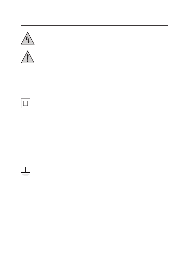
4. SYMBOL-ERKLÄRUNGEN
Ein Blitzsymbol im Dreieck warnt vor einem elektrischen Schlag oder der
Beeinträchtigung der elektrischen Sicherheit des Geräts.
Das Symbol mit dem Ausrufezeichen im Dreieck weist auf wichtige Hinweise in
dieser Bedienungsanleitung hin, die unbedingt zu beachten sind.
Das „Pfeil“-Symbol ist zu finden, wenn besondere Tipps und Hinweise zur Bedienung
¼
gegeben werden.
CAT II Überspannungskategorie II für Messungen an elektrischen und elektronischen
CAT III Überspannungskategorie III für Messungen in der Gebäudeinstallation (z.B.
CAT IV Überspannungskategorie IV für Messungen an der Quelle der
Dieses Gerät ist CE-konform und erfüllt die erforderlichen europäischen
Richtlinien
Schutzklasse II (doppelte oder verstärkte Isolierung)
Geräten, welche über einen Netzstecker mit Spannung versorgt werden. Diese
Kategorie umfasst auch alle kleineren Kategorien (z.B. CATI zur Messung von
Signal- und Steuerspannungen).
Steckdosen oder Unterverteilungen). Diese Kategorie umfasst auch alle
kleineren Kategorien (z.B. CAT II zur Messung an Elektrogeräten).
Niederspannungsinstallation (z.B. Hauptverteilung, Haus-Übergabepunkte der
Energieversorger etc.). Diese Kategorie umfasst auch alle kleineren
Kategorien.
Erdpotential
6
Page 7

5. SICHERHEITSHINWEISE
Bei Schäden, die durch Nichtbeachtung dieser Bedienungsanleitung
verursacht werden, erlischt die Gewährleistung/Garantie. Für Folgeschäden übernehmen wir keine Haftung!
Bei Sach- oder Personenschäden, die durch unsachgemäße Handhabung
oder Nichtbeachten der Sicherheitshinweise verursacht werden,
übernehmen wir keine Haftung! In solchen Fällen erlischt die Gewährleistung/Garantie.
Sehr geehrte Kundin, sehr geehrter Kunde,
diese Sicherheitshinweise dienen nicht nur zum Schutz des Produkts, sondern
auch zu Ihrer eigenen Sicherheit und der anderer Personen. Lesen Sie sich
deshalb dieses Kapitel sehr aufmerksam durch, bevor Sie das Produkt in
Betrieb nehmen!
Dieses Produkt hat das Werk in sicherheitstechnisch einwandfreien Zustand
verlassen. Um diesen Zustand zu erhalten und einen gefahrlosen Betrieb
sicherzustellen, muss der Anwender die Sicherheitshinweise und Warnvermerke beachten, die in dieser Gebrauchsanweisung enthalten sind.
• Aus Sicherheits- und Zulassungsgründen (CE) ist das eigenmächtige
Umbauen und/oder Verändern des Produkts nicht gestattet.
• Messgeräte und Zubehör sind kein Spielzeug und gehören nicht in
Kinderhände.
• Das Produkt ist nur für den Betrieb in trockener Umgebung geeignet. Das
gesamte Produkt darf nicht feucht oder nass werden, fassen Sie es niemals
mit nassen Händen an! Es besteht Lebensgefahr durch einen elektrischen
Schlag!
Achten Sie darauf, dass ihre Hände, Schuhe, Kleidung, der Boden,
Schaltungen und Schaltungsteile usw. unbedingt trocken sind.
• Verwenden Sie das Produkt niemals gleich dann, wenn es von einem kalten
in einen warmen Raum gebracht wird. Das dabei entstehende Kondenswasser kann unter Umständen das Produkt zerstören. Lassen Sie das Produkt
zuerst auf Zimmertemperatur kommen, bevor es verwendet wird.
• Das Produkt darf nicht in explosionsgefährdeten Bereichen eingesetzt
werden.
7
Page 8

• Überprüfen Sie vor jeder Messung die Stromzange bzw. die Messleitungen
auf Beschädigungen. Führen Sie niemals Messungen durch, wenn Produkt
und/oder die Messleitungen beschädigt sind!
• Verwenden Sie die Stromzange nicht kurz vor, während oder kurz nach
einem Gewitter (Blitzschlag; energiereiche Überspannungen!).
• Stellen Sie an der Stromzange vor jeder Messung den gewünschten
Messbereich ein. Eine falsche Messung könnte das Produkt zerstören!
Stellen Sie vor jeder Spannungsmessung sicher, dass sich die Stromzange
nicht im Strommessbereich befindet.
• Vor jedem Wechsel des Messbereiches sind die Messspitzen vom
Messobjekt zu entfernen.
• Um einen elektrischen Schlag zu vermeiden, achten Sie darauf, dass Sie die
zu messenden Anschlüsse/Messpunkte während der Messung nicht, auch
nicht indirekt, berühren. Über die fühlbaren Griffbereichsmarkierungen an
den Messspitzen darf während des Messens nicht gegriffen werden.
• Entfernen Sie vor dem Anschluss der Messleitungen die Staubschutzkappen
an den Anschlussbuchsen. Montieren Sie diese stets nach jeder Messung,
um eine Verschmutzung der Kontakte zu vermeiden.
• Beachten Sie bei jeder Messung die Beschreibung der Abbildungen in jedem
Kapitel. Eine falsche Messung könnte das Produkt zerstören.
• Die Spannung zwischen den Anschlusspunkten darf die im Kapitel
„Technische Daten“ angegebene Spannung nicht überschreiten.
• Seien Sie besonders vorsichtig beim Umgang mit Spannung >25 V/AC bzw.
>35 V/DC! Bereits bei diesen Spannungen können Sie bei Berührung
elektrischer Leiter einen lebensgefährlichen elektrischen Schlag bekommen.
• Berühren Sie während einer Messung niemals die Messspitzen!
• Achten Sie bei jeder Messung darauf, dass sich die Anschlüsse/Messpunkte
nicht berühren. Kurzschlussgefahr!
• Achten Sie bei jeder Messung darauf, dass durch den Stromzangen-Sensor
keine Gegenstände wie z.B. Kabel gequetscht werden.
• Vermeiden Sie den Betrieb in unmittelbarer Nähe von starken magnetischen
oder elektromagnetischen Feldern bzw. Sendeantennen oder HFGeneratoren, da hierbei der Messwert verfälscht werden kann.
8
Page 9

• Wenn anzunehmen ist, dass ein gefahrloser Betrieb nicht mehr möglich ist,
so ist das Gerät außer Betrieb zu setzen und gegen unbeabsichtigten
Betrieb zu sichern. Es ist anzunehmen, dass ein gefahrloser Betrieb nicht
mehr möglich ist, wenn:
- das Gerät sichtbare Beschädigungen aufweist,
- das Gerät nicht mehr arbeitet und
- das Gerät längere Zeit unter ungünstigen Verhältnissen gelagert wurde
- schwere Transportbeanspruchungen aufgetreten sind
• In gewerblichen Einrichtungen sind die Unfallverhütungsvorschriften des
Verbandes der gewerblichen Berufsgenossenschaften für elektrische
Anlagen und Betriebsmittel zu beachten.
• In Schulen und Ausbildungseinrichtungen, Hobby- und Selbsthilfewerkstätten ist der Umgang mit Messgeräten durch geschultes Personal
verantwortlich zu überwachen.
• Lassen Sie das Verpackungsmaterial nicht achtlos liegen, dieses könnte für
Kinder zu einem gefährlichen Spielzeug werden.
• Gehen Sie vorsichtig mit dem Produkt um, durch Stöße, Schläge oder dem
Fall aus bereits geringer Höhe wird es beschädigt.
• Sollten Sie sich über den korrekten Betrieb nicht im Klaren sein oder sollten
sich Fragen ergeben, die nicht im Laufe der Bedienungsanleitung abgeklärt
werden, so setzen Sie sich mit uns oder einem anderen Fachmann in
Verbindung.
9
Page 10

6. BATTERIE-/AKKUHINWEISE
• Batterien/Akkus gehören nicht in Kinderhände.
• Lassen Sie Batterien nicht offen herumliegen, es besteht die Gefahr, dass diese von
Kindern oder Haustieren verschluckt werden. Suchen Sie im Falle eines Verschluckens
sofort einen Arzt auf.
• Ausgelaufene oder beschädigte Batterien/Akkus können bei Berührung mit der Haut
Verätzungen verursachen. Benutzen Sie deshalb in diesem Fall geeignete Schutzhandschuhe.
Aus Batterien/Akkus auslaufende Flüssigkeiten sind chemisch sehr aggressiv.
Gegenstände oder Oberflächen, die damit in Berührung kommen, können teils massiv
beschädigt werden. Bewahren Sie Batterien/Akkus deshalb an einer geeigneten Stelle
auf.
• Batterien/Akkus dürfen nicht kurzgeschlossen, zerlegt oder ins Feuer geworfen werden.
Es besteht Explosionsgefahr.
• Herkömmliche nicht wiederaufladbare Batterien dürfen nicht aufgeladen werden, es
besteht Explosionsgefahr!
• Achten Sie beim Einlegen/Anschluss der Batterie auf die richtige Polung (Plus/+ und
Minus/- beachten).
• Die Stromzange lässt sich zwar prinzipbedingt auch mit einem Akku betreiben, wir
empfehlen Ihnen jedoch, aus Gründen der Betriebssicherheit und der Betriebsdauer
eine hochwertige Alkaline-Batterie zu verwenden.
10
Page 11
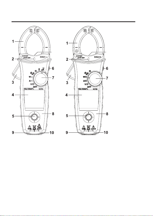
7. BEDIENELEMENTE
VC731: VC732:
11
1 Stromzangen-Sensor
2 LED-Anzeige für kontaktlose Spannungserkennung
3 Öffnungshebel für Stromzangen-Sensor
4 LC-Display
5 Navigations-Joystick
6 Taste „HOLD“
7 Einstellrad für Messungsart
8 Rückseitiges Batteriefach
9 Buchse „COM“
10 Anschlussbuchse für Messung von Spannung, Widerstand und Kapazität
11 Weiße LED zur Beleuchtung des Arbeitsfelds (nur bei geöffnetem Stromzangen-
Sensor)
11
11
Page 12
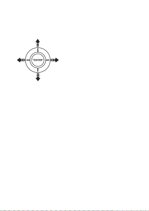
Der Navigations-Joystick (5) dient zur Steuerung der Anzeigen/Menüs. Dabei entspricht
eine Bewegung des Joysticks nach oben, unten, links und rechts einer entsprechenden
Steuerbewegung in den Anzeigen/Menüs.
Wird der Navigations-Joystick wie eine herkömmliche Taste gedrückt, so entspricht dies
einer Bestätigung einer Einstellung oder einer Auswahl („ENTER“).
Wenn die Stromzange eingeschaltet ist, wird die weiße LED (11) beim Betätigen des
Öffnungshebels der Stromzange automatisch aktiviert und beim Schließen wieder
deaktiviert. Die Beleuchtung erleichtert beispielsweise die korrekte Platzierung des
Stromzangen-Sensors in dunklen Schaltschränken.
Die Hintergrundbeleuchtung des LC-Displays schaltet sich nach ca. 15 Sekunden
automatisch aus, um Strom zu sparen. Wenn Sie das Einstellrad (7) oder den NavigationsJoystick (5) bewegen/betätigen, so wird die Hintergrundbeleuchtung erneut für 15
Sekunden aktiviert.
12
Page 13
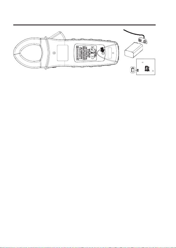
8. BATTERIE EINLEGEN/WECHSELN
• Beenden Sie zunächst jeglichen Messvorgang und entfernen Sie die Messkabel aus der
Stromzange.
• Schalten Sie die Stromzange aus.
• Entfernen Sie auf der Rückseite der Stromzange die Abdeckung für das Batteriefach,
indem Sie die Befestigungsschraube (siehe Pfeilmarkierung im Bild oben) mittels einem
kleinen Kreuz-Schraubendreher herausdrehen.
• Entfernen Sie eine leere Batterie aus dem Batteriefach.
• Schließen Sie eine neue Batterie an dem Batterieclips an. Durch die spezielle Bauform
von Batterieclips und 9 V-Block ist die Verbindung verpolungssicher.
• Setzen Sie die Batterie in das Batteriefach ein.
• Setzen Sie den Batteriefachdeckel wieder ein. Achten Sie dabei darauf, dass das
Batteriekabel nicht eingequetscht wird.
• Zuletzt drehen Sie die Befestigungsschraube sorgfältig fest. Wenden Sie dabei jedoch
keine Gewalt an.
13
Page 14
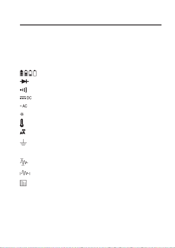
9. DISPLAYANZEIGE UND SYMBOLE
OFF Die Stromzange befindet sich im Ruhezustand
REL Relativwertmessung
AUTO Automatische Messbereichswahl
APO „Auto-Power-Off“
HOLD Aktivierte Hold-Funktion
Statusanzeige für Batterie-/Akkuzustand
Diodentest
Akustischer Durchgangsprüfer
Gleichspannung/Gleichstrom
Wechselspannung/Wechselstrom
Kapazität
Temperatur (nur VC731)
Mikroampere-Messung (nur VC731)
Erdpotential
OL Überschreiten des Messbereichs
Spitzenspannung/Spitzenstrom („Peak“)
Anlaufstrom („Inrush“)
Harmonische Verzerrung
THD Oberwellengehalt
14
Page 15
10. INBETRIEBNAHME
Nach dem Einlegen der Batterie können Sie mit dem gewünschten Messvorgang
beginnen.
Wählen Sie dafür über das Einstellrad (7) den gewünschten Messbereich.
Das LC-Display leuchtet auf und die Stromzange ist betriebsbereit.
Einzelheiten zu den verschiedenen Messungen entnehmen Sie bitte dem Kapitel 11.
Um Energie zu sparen, schaltet sich die Stromzange nach 15 Minuten Inaktivität
automatisch ab.
Um eine Messung fortführen zu können, bewegen Sie das Einstellrad (7) auf die
¼
Position „OFF“ und wählen dann erneut Ihren gewünschten Messbereich.
Beachten Sie bei den unterschiedlichen Messarten unbedingt die Beschreibung der einzelnen Abbildungen in jedem Kapitel!
15
Page 16

11. BEDIENUNG
a) HOLD-Funktion
Mit der HOLD-Funktion wird der aktuelle Messwert im Display dauerhaft angezeigt und die
Messung damit unterbrochen.
Dazu drücken Sie während einer Messung kurz die Taste „HOLD“ (6). Im Display erscheint
„HOLD“. Zum Deaktivieren drücken Sie erneut kurz die Taste „HOLD“ (6). Sie können mit
der Messung fortfahren.
b) NCV-Funktion (kontaktlose Spannungserkennung)
Durch die NCV-Funktion („non-contact-voltage detection“) wird berührungslos das
Vorhandensein von Spannung an Leitern detektiert. Der NCV-Sensor ist an der Spitze des
Strom-Sensors angebracht.
Führen Sie den NCV-Sensor an einen Leiter. Bei Vorhandensein von Spannung leuchtet
die rote LED (2). Diese Funktion ist nur bei eingeschalteter Stromzange aktiv.
Durch den hochempfindlichen NCV-Sensor kann die LED auch bei statischen
¼
Aufladungen kurz aufleuchten. Dies ist normal und keine Fehlfunktion.
Testen Sie diese Funktion immer zuerst an einer bekannten Spannungsquelle, um
Fehldetektionen zu vermeiden. Bei Fehldetektion besteht die Gefahr eines elektrischen
Schlages!
16
Page 17
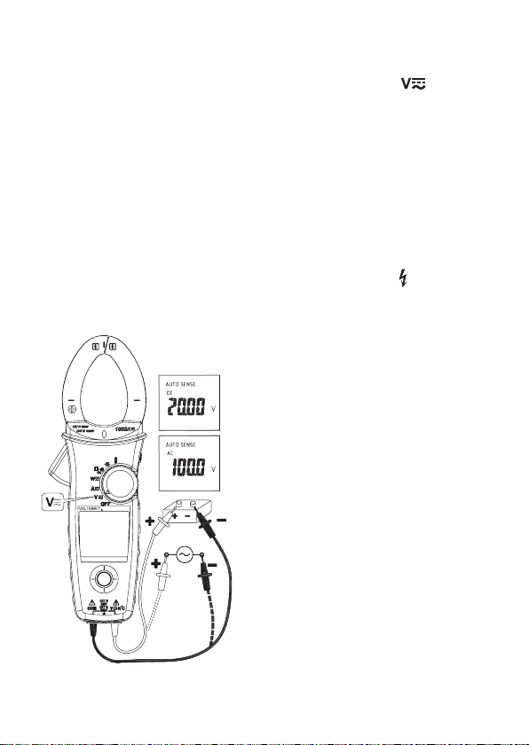
c) Spannungsmessung
• Bewegen Sie das Einstellrad (7) auf das Symbol zur Spannungsmessung „ “.
• Schließen Sie die Messleitungen an die Stromzange an.
• Nachdem Einschalten steht der Messbereich immer auf „AUTO SENSE“ für eine
automatische Erkennung der Messgröße AC oder DC.
• Wählen Sie mittels dem Navigations-Joystick (5) die Funktion „AC“, „DC“ oder „AC+DC“.
Es ertönt ein kurzer Signalton. Bestätigen Sie die Auswahl durch Drücken des
Navigations-Joysticks („ENTER“).
• Verbinden Sie die beiden Messspitzen mit dem Messobjekt. Messen Sie immer parallel
zum jeweiligen Verbraucher.
• Der Messwert wird im LC-Display angezeigt.
Bei Spannungen größer als 30 V erscheint im LC-Display das Symbol „ “.
¼
• Entfernen Sie nach der Messung die Messleitungen vom Messobjekt und schalten Sie
die Stromzange aus. Drehen Sie dafür das Einstellrad (7) in die Position „OFF“.
17
Page 18
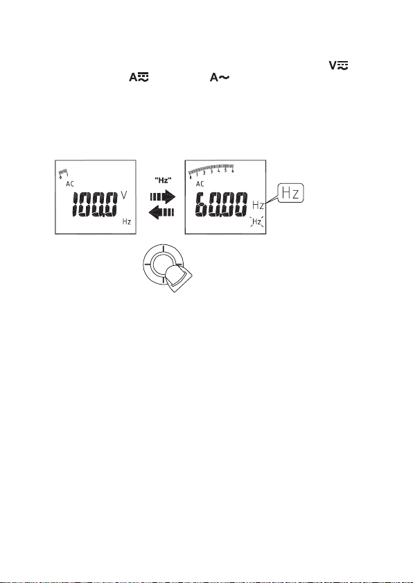
d) Frequenzmessung
• Bewegen Sie das Einstellrad (7) auf das Symbol zur Spannungsmessung „ “ oder
zur Strommessung „ “ (VC732) bzw. „ “ (VC731). Beachten Sie dabei die
Informationen zur Spannungs-/Strommessung in Kapitel 11 c) und 11. j).
• Um die Frequenz zu messen (nur bei Wechselspannung möglich), wählen Sie mit dem
Navigations-Joystick (5) das Symbol „Hz“ aus. Bestätigen Sie die Auswahl durch
Drücken des Navigations-Joysticks („ENTER“).
• Die Frequenz wird im LC-Display angezeigt.
18
Page 19
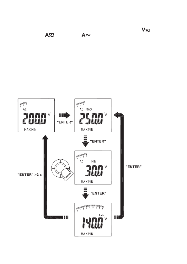
e) MAX-/MIN-Werte anzeigen
• Bewegen Sie das Einstellrad (7) auf das Symbol zur Spannungsmessung „ “ bzw.
Strommessung „ “ (VC732) bzw. „ “ (VC731). Beachten Sie dabei die
Informationen zur Spannungs-/Strommessung in Kapitel 11 c) und 11. j).
• Um MAX-/MIN-Werte anzuzeigen, wählen Sie mit dem Navigations-Joystick (5) das
Symbol „MAX/MIN“ aus. Bestätigen Sie die Auswahl durch Drücken des NavigationsJoysticks („ENTER“).
• Die Werte werden während der Messung stets aktualisiert.
• Drücken Sie erneut kurz den Navigations-Joystick („ENTER“), damit die Werte „MAX“
(Maximum), „MIN“ (Minimum) oder den Durchschnittswert „AVG“ anzeigen zu lassen.
• Beenden Sie diesen Modus, indem Sie für mindestens 2 Sekunden den NavigationsJoystick drücken („ENTER“).
19
Page 20
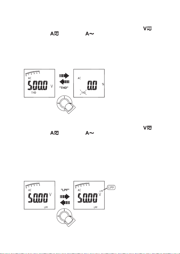
f) THD-Messung (Oberwellengehalt)
• Bewegen Sie das Einstellrad (7) auf das Symbol zur Spannungsmessung „ “ bzw.
Strommessung „ “ (VC732) bzw. „ “ (VC731). Beachten Sie dabei die
Informationen zur Spannungs-/Strommessung in Kapitel 11 c) und 11. j).
• Für die Messung des Oberwellengehalts (nur im AC-Modus möglich), wählen Sie mit
dem Navigations-Joystick (5) das Symbol „THD“ aus. Bestätigen Sie die Auswahl durch
Drücken des Navigations-Joysticks („ENTER“).
• Der Wert erscheint im LC-Display.
g) LPF-Messung (Low-Pass-Filter)
• Bewegen Sie das Einstellrad (7) auf das Symbol zur Spannungsmessung „ “ bzw.
Strommessung „ “ (VC732) bzw. „ “ (VC731). Beachten Sie dabei die
Informationen zur Spannungs-/Strommessung in Kapitel 11 c) und 11. j).
• Für die Anzeige des LPF-Indikators (nur im AC-Modus möglich), wählen Sie mit dem
Navigations-Joystick (5) das Symbol „LPF“ aus. Bestätigen Sie die Auswahl durch
kurzes Drücken des Navigations-Joysticks („ENTER“).
• Um den Modus zu beenden, drücken Sie für mindestens 2 Sekunden den NavigationsJoystick („ENTER“).
• Der Wert erscheint im LC-Display.
20
Page 21
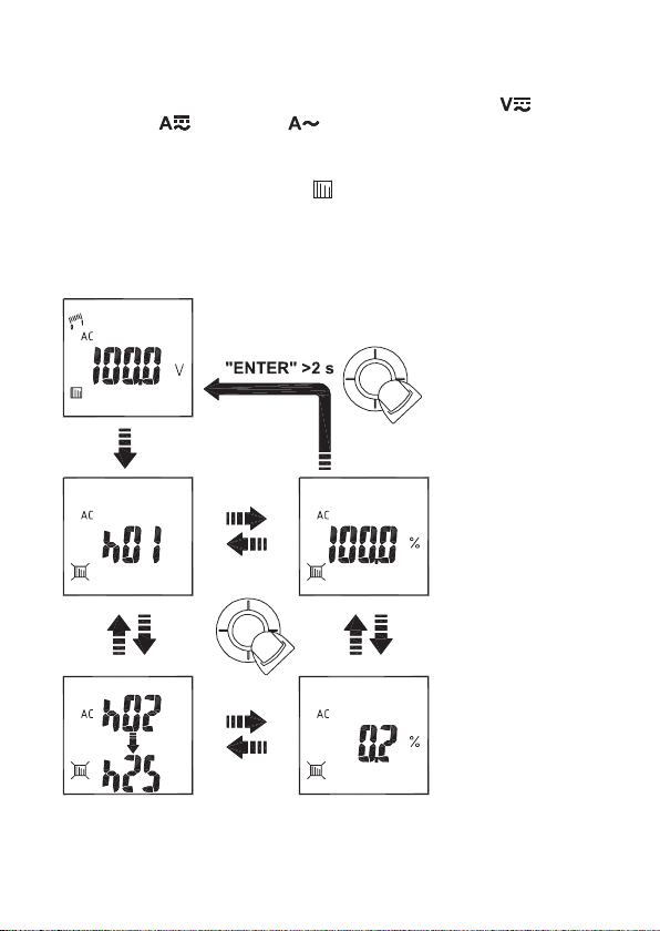
h) Harmonische Verzerrung (Oberwellenanteil)
• Bewegen Sie das Einstellrad (7) auf das Symbol zur Spannungsmessung „ “ bzw.
Strommessung „ “ (VC732) bzw. „ “ (VC731). Beachten Sie dabei die
Informationen zur Spannungs-/Strommessung in Kapitel 11 c) und 11. j).
• Zur Messung der harmonischen Verzerrung (nur im AC-Modus möglich), wählen Sie mit
dem Navigations-Joystick (5) das Symbol „ “ aus. Bestätigen Sie die Auswahl durch
Drücken des Navigations-Joysticks („ENTER“).
• Um den Modus zu beenden, drücken Sie für mindestens 2 Sekunden den NavigationsJoystick („ENTER“).
• Der Wert erscheint im LC-Display.
21
Page 22
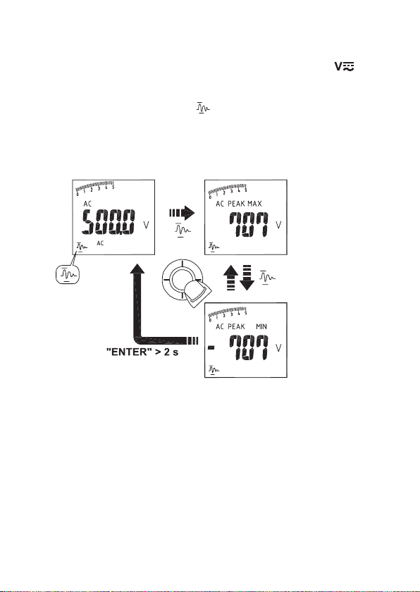
i) Spannungsspitzen („Peak“) messen
• Bewegen Sie das Einstellrad (7) auf das Symbol zur Spannungsmessung „ “.
Beachten Sie die Informationen zur Spannungsmessung, Kapitel 11 c).
• Um Spannungsspitzen zu messen (nur im AC-Modus möglich), wählen Sie mit dem
Navigations-Joystick (5) das Symbol „ “ aus. Bestätigen Sie die Auswahl durch
Drücken des Navigations-Joysticks („ENTER“).
• Um den Modus zu beenden, drücken Sie für mindestens 2 Sekunden den NavigationsJoystick („ENTER“).
• Der Wert erscheint im LC-Display.
22
Page 23
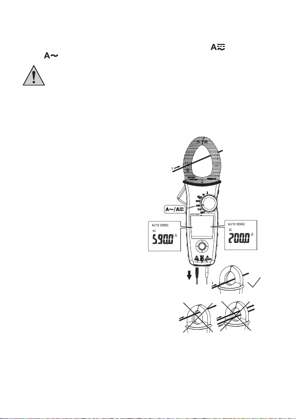
j) Strommessung
• Bewegen Sie das Einstellrad (7) auf das Symbol zur Strommessung „ “ (VC732)
bzw. „ “ (VC731).
Umfassen Sie mit der Stromzange immer nur einen Leiter. Werden mehrere
Leiter umfasst, erhalten Sie kein vernünftiges Messergebnis.
Durch den Dauermagnetismus des Strom-Sensors kann bei der Strommessung ein geringer Strom im LC-Display angezeigt werden, auch wenn kein
Leiter umfasst wird.
Um die Anzeige auf „0“ zu setzen (nur beim VC732), drücken Sie für mindestens 2
¼
Sekunden auf die Taste „HOLD“. Die Anzeige wird zurückgesetzt.
• Entfernen Sie vor der Strommessung die
Messleitungen von der Stromzange, falls
noch angeschlossen.
• Wählen Sie mittels dem NavigationsJoystick (5) die Funktion „AC“, „DC“ oder
„AC+DC“ (nur VC732). Es ertönt ein kurzer
Signalton. Bestätigen Sie die gewünschte
Funktion durch Drücken des NavigationsJoysticks („ENTER“).
• Öffnen Sie den Stromzangen-Sensor (1)
mit dem Öffnungshebel (3). Umfassen Sie
mit der Stromzange den Leiter, welcher
gemessen werden soll und schließen Sie
den Stromzangen-Sensor (1) wieder.
Während der Stromzangen-Sensor geöffnet
ist, wird Ihnen das Arbeitsfeld mittels einer
LED ausgeleuchtet.
• Der Strom wird im LC-Display angezeigt.
• Zum Beenden der Messung nehmen Sie
den Stromzangen-Sensor (1) wieder vom
Leiter ab und schalten Sie die Stromzange
aus. Drehen Sie dafür das Einstellrad (7)
auf die Position „OFF“.
23
Page 24
k) Stromspitzen („Peak“) messen
• Bewegen Sie das Einstellrad (7) auf das Symbol zur Strommessung „ “ (VC732)
bzw. „ “ (VC731). Beachten Sie dabei die Informationen zur Strommessung in
Kapitel 11 j).
• Um Stromspitzen zu messen (nur im AC-Modus möglich), wählen Sie mit dem
Navigations-Joystick (5) das Symbol „ “ aus. Bestätigen Sie die Auswahl durch
Drücken des Navigations-Joysticks („ENTER“) für die Dauer von mindestens 2
Sekunden. Im LC-Display erscheint „PEAK“.
• Um den Modus zu beenden, drücken Sie für mindestens 2 Sekunden die NavigationsTaste („ENTER“).
• Der Wert wird im LC-Display angezeigt.
24
Page 25
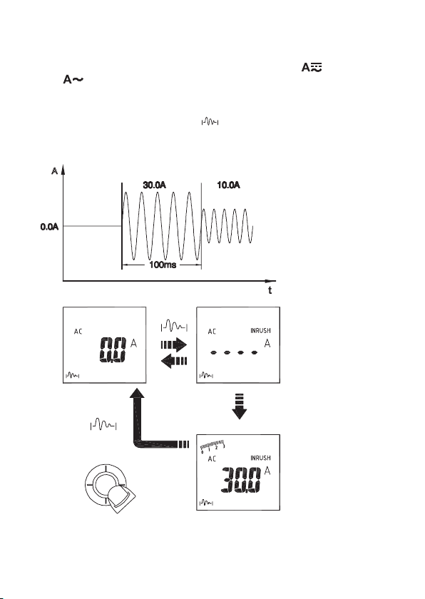
l) Anlaufstrom („Inrush“) messen
• Bewegen Sie das Einstellrad (7) auf das Symbol zur Strommessung „ “ (VC732)
bzw. „ “ (VC731). Beachten Sie dabei die Informationen zur Strommessung in
Kapitel 11 j).
• Um den Anlaufstrom („Inrush“) zu messen (nur im AC-Modus möglich), wählen Sie mit
dem Navigations-Joystick (5) das Symbol „ “ aus. Bestätigen Sie die Auswahl durch
Drücken des Navigations-Joysticks („ENTER“). Im LC-Display erscheint „INRUSH“.
• Der Wert wird im LC-Display angezeigt.
25
Page 26
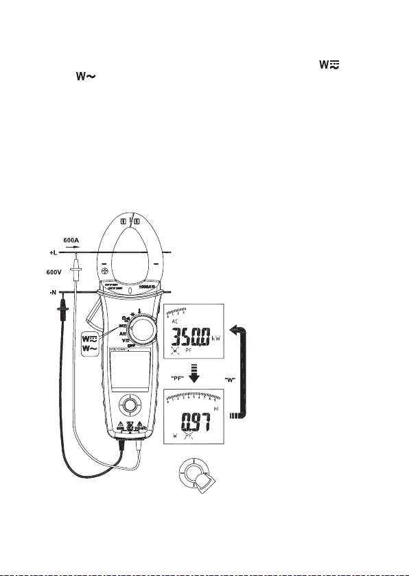
m) Leistungsmessung
• Bewegen Sie das Einstellrad (7) auf das Symbol zur Leistungsmessung „ “ (VC732)
bzw. „ “ (VC731).
• Schließen Sie die Messleitungen an die Stromzange an.
• Für eine 1-Phasen-Messung verbinden Sie die rote Messleitung mit der Phase „L“ und
die schwarze Messleitung mit dem Neutralleiter.
• Für die Anzeige des Leistungsfaktors („cosPHI“), wählen Sie mit dem NavigationsJoystick (5) das Symbol „PF“. Bestätigen Sie die Auswahl durch Drücken des
Navigations-Joysticks („ENTER“).
• Die Leistung wird im LC-Display angezeigt.
1-Phasen-Messung:
26
Page 27
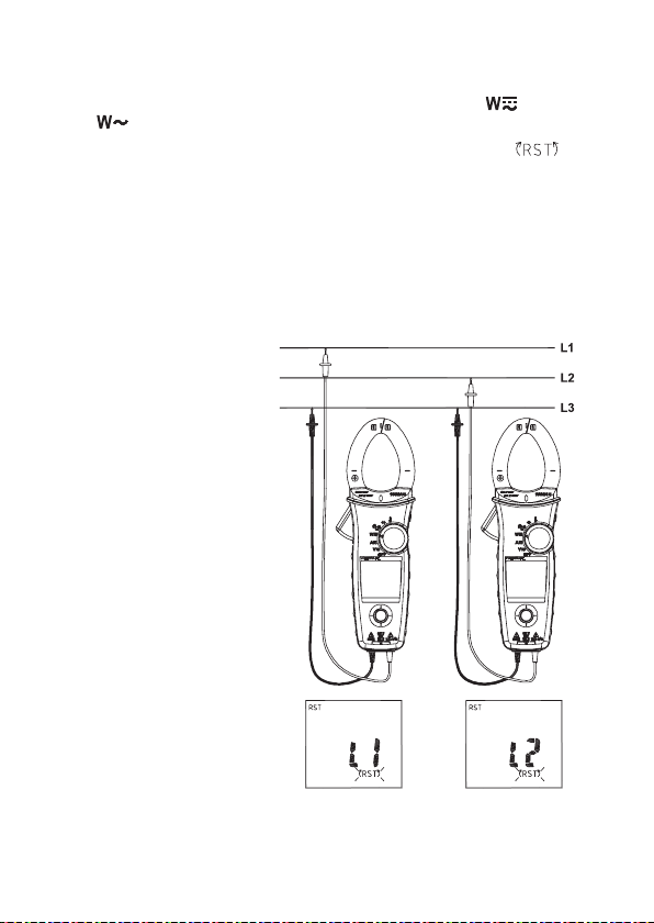
n) Phasenprüfung
• Bewegen Sie das Einstellrad (7) auf das Symbol zur Leistungsmessung „ “ (VC732)
bzw. „ “ (VC731).
• Zur Phasenprüfung wählen Sie mit dem Navigations-Joystick (5) das Symbol „ “
aus. Bestätigen Sie die Auswahl durch Drücken des Navigations-Joysticks („ENTER“).
• Verbinden Sie die rote Messleitung mit der Phase 1 und die schwarze Messleitung mit
der Phase 3. Es ertönen zwei kurze Signaltöne. Wechseln Sie rote Messleitung zügig
auf die Phase 2.
• Im LC-Display erscheint „123“ für ein rechtsdrehendes und „321“ für ein linksdrehendes
Feld.
• Bei Spannungen >1000 V erscheint „OLU“ im LC-Display. Bei Spannungen <30 V
erscheint „LoU“.
• Erscheint „- - - -“ im Display, wird
vom Messgerät kein Wert erkannt.
• Ist die Frequenz >65 Hz oder
<45 Hz, so erscheint „outF“ im LCDisplay.
• Das Messergebnis wird Ihnen nach
kurzer Zeit im LC-Display
angezeigt.
• Entfernen Sie nach der Messung
die Messleitungen vom Messobjekt
und schalten Sie die Stromzange
aus. Drehen Sie dafür das
Einstellrad (7) in die Position
„OFF“.
27
Page 28
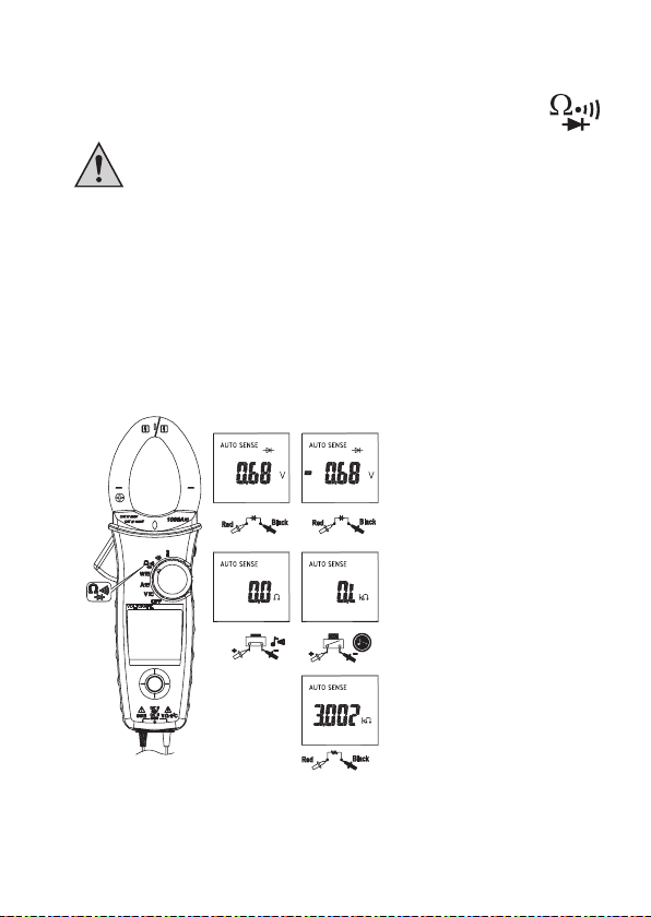
o) Widerstandsmessung
• Bewegen Sie das Einstellrad (7) auf das Symbol zur Widerstandsmessung,
siehe Bild rechts.
Vergewissern Sie sich, dass alle zu messenden Schaltungsteile, Schaltungen
und Bauelemente sowie andere Messobjekte unbedingt spannungslos und
entladen sind.
• Schließen Sie die Messleitungen an die Stromzange an.
• Überprüfen Sie vor der Messung die Messleitungen auf Durchgang. Verbinden Sie dazu
die beiden Messspitzen miteinander. Hierbei muss im LC-Display ein Widerstandswert
von ca. 0,5 Ω angezeigt werden (Eigenwiderstand der Messleitungen).
• Verbinden Sie nun die Messleitungen mit dem Messobjekt.
• Sobald „OL“ im LC-Display erscheint, haben Sie den Messbereich überschritten bzw. der
Messkreis ist unterbrochen.
• Entfernen Sie nach der Messung die Messleitungen vom Messobjekt und schalten Sie
die Stromzange aus. Drehen Sie dafür das Einstellrad (7) in die Position „OFF“.
28
Page 29
p) Durchgangsprüfung
• Bewegen Sie das Einstellrad (7) auf das Symbol zur Widerstandsmessung,
siehe Bild rechts.
Vergewissern Sie sich, dass alle zu messenden Schaltungsteile, Schaltungen
und Bauelemente sowie andere Messobjekte unbedingt spannungslos und
entladen sind.
• Schließen Sie die Messleitungen an die Stromzange an.
• Wählen Sie mit dem Navigations-Joystick (5) das Symbol zur Durchgangsprüfung aus.
Bestätigen Sie die Auswahl durch Drücken des Navigations-Joysticks („ENTER“).
• Verbinden Sie die Messspitzen mit dem Messobjekt.
• Als Durchgang wird ein Messwert <30 - 100 Ω erkannt. Hierbei ertönt ein Signalton.
• Entfernen Sie nach der Messung die Messleitungen vom Messobjekt und schalten Sie
die Stromzange aus. Drehen Sie dafür das Einstellrad (7) in die Position „OFF“.
q) Diodentest
• Bewegen Sie das Einstellrad (7) auf das Symbol zur Widerstandsmessung,
siehe Bild rechts.
Vergewissern Sie sich, dass alle zu messenden Schaltungsteile, Schaltungen
und Bauelemente sowie andere Messobjekte unbedingt spannungslos und
entladen sind.
• Schließen Sie die Messleitungen an die Stromzange an.
• Wählen Sie mit dem Navigations-Joystick (5) das Symbol für Diodentest „
Bestätigen Sie die Auswahl durch Drücken des Navigations-Joysticks („ENTER“).
• Verbinden Sie die beiden Messspitzen mit dem Messobjekt (Diode).
• Im LC-Display wird die Durchlassspannung in Volt angezeigt. Wird „OL“ angezeigt, so
wird die Diode in Sperrrichtung gemessen oder die Diode ist defekt. Führen Sie in
diesem Fall zur Kontrolle eine gegenpolige Messung durch.
• Entfernen Sie nach der Messung die Messleitungen vom Messobjekt und schalten Sie
die Stromzange aus. Drehen Sie dafür das Einstellrad (7) in die Position „OFF“.
“ aus.
29
Page 30
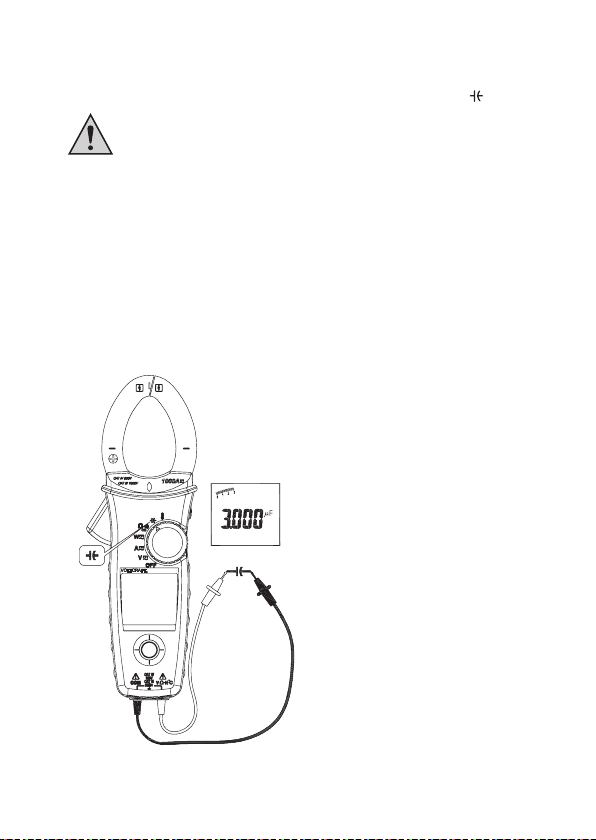
r) Kapazitätsmessung
• Bewegen Sie das Einstellrad (7) auf das Symbol zur Kapazitätsmessung „ “.
Vergewissern Sie sich, dass alle zu messenden Schaltungsteile, Schaltungen
und Bauelemente sowie andere Messobjekte unbedingt spannungslos und
entladen sind.
Beachten Sie z.B. bei Elektrolyt-Kondensatoren unbedingt die Polarität!
• Schließen Sie die Messleitungen an die Stromzange an.
• Messen Sie mittels den Messleitungen am Messobjekt. (Rot = Pluspol, Schwarz =
Minuspol).
Während sich der Kondensator entlädt, wird „diSC“ angezeigt (= „Discharging“ =
Entladen).
• Der Wert wird im LC-Display angezeigt.
• Entfernen Sie nach der Messung die Messleitungen vom Messobjekt und schalten Sie
die Stromzange aus. Drehen Sie das Einstellrad (7) in die Position „OFF“.
30
Page 31

s) Temperaturmessung (nur VC731)
• Bewegen Sie das Einstellrad (7) auf das Symbol zur Temperaturmessung „ “.
• Schließen Sie den Temperaturadapter an die Stromzange an.
• Wählen Sie über den Navigations-Joystick (5) die Temperatureinheit „°C“ (Grad Celsius)
oder „°F“ (Grad Fahrenheit) aus. Bestätigen Sie die Auswahl durch Drücken des
Navigations-Joysticks („ENTER“).
• Halten Sie den Temperaturfühler an das Messobjekt.
• Die Temperatur wird im LC-Display angezeigt.
• Entfernen Sie nach der Messung den Temperaturadapter vom Messobjekt und schalten
Sie die Stromzange aus. Drehen Sie dafür das Einstellrad (7) in die Position „OFF“.
31
Page 32

t) Mikroampere-Messung (nur VC731)
• Bewegen Sie das Einstellrad (7) auf das Symbol zur Mikroampere-Messung „ “.
• Trennen Sie wenn nötig den Stromkreis.
• Messen Sie immer in Reihe zum jeweiligen Verbraucher.
• Der Messwert wird im LC-Display angezeigt.
• Entfernen Sie nach der Messung die Messleitungen vom Messobjekt und schalten Sie
die Stromzange aus. Drehen Sie dafür das Einstellrad (7) in die Position „OFF“.
32
Page 33

12. WARTUNG UND REINIGUNG
a) Allgemein
Die Stromzange ist bis auf einen gelegentlichen Batteriewechsel wartungsfrei.
Überlassen Sie eine Wartung oder Reparatur einem Fachmann.
Um die Messgenauigkeit der Stromzange über einen langen Zeitraum hinweg zu
gewährleisten, empfiehlt es sich, das Produkt einmal jährlich kalibrieren zu lassen.
b) Reinigung
Vor der Reinigung des Produktes müssen alle angeschlossenen Leitungen von der
Stromzange und von allen Messobjekten getrennt werden. Schalten Sie die Stromzange
aus.
Für eine Reinigung verwenden Sie nur ein weiches, trockenes und sauberes Tuch.
Drücken Sie nicht zu stark auf das Display, da dies nicht nur zu Kratzspuren führt, sondern
auch zu einer Beschädigung des Displays.
Staub kann sehr einfach mit einem weichen, sauberen Pinsel und einem Staubsauger
entfernt werden.
Verwenden Sie auf keinen Fall aggressive Reinigungsmittel oder chemische Lösungen, da
sonst die Oberfläche des Gehäuses beschädigt werden könnte.
33
Page 34

13. ENTSORGUNG
a) Allgemein
Entsorgen Sie das Produkt am Ende seiner Lebensdauer gemäß den
geltenden gesetzlichen Bestimmungen.
b) Batterien/Akkus
Sie als Endverbraucher sind gesetzlich (Batterieverordnung) zur Rückgabe aller
gebrauchten Batterien und Akkus verpflichtet; eine Entsorgung über den Hausmüll ist
untersagt!
Schadstoffhaltige Batterien/Akkus sind mit nebenstehendem Symbol
gekennzeichnet, das auf das Verbot der Entsorgung über den Hausmüll
hinweist.
Die Bezeichnungen für das ausschlaggebende Schwermetall sind: Cd=Cadmium,
Hg=Quecksilber, Pb=Blei (Bezeichnung steht auf Batterie/Akku z.B. unter dem links
abgebildeten Mülltonnen-Symbol).
Ihre verbrauchten Batterien/Akkus können Sie unentgeltlich bei den Sammelstellen Ihrer
Gemeinde, unseren Filialen oder überall dort abgeben, wo Batterien/Akkus verkauft
werden!
Sie erfüllen damit die gesetzlichen Verpflichtungen und leisten Ihren Beitrag zum
Umweltschutz.
34
Page 35

14. TECHNISCHE DATEN
Stromversorgung ............................... 1x Batterie 9 V-Block
Betriebsdauer ..................................... ca. 50 h (ohne Hintergrundbeleuchtung)
Abschaltfunktion ................................ nach 15 Minuten
Messrate............................................. 3 Messungen / s
Messkategorie.................................... CAT IV 600 V, CAT III 1000 V
Öffnungsbereich Stromzange ........... 37 mm
Abmessungen .................................... 242 x 87,5 x 50,5 mm (L x B x H)
Gewicht .............................................. ca. 435 g (mit Batterie)
Temperaturbereich ............................ 0 °C bis +10 °C
+10 °C bis +30 °C (< 80% relative Luftfeuchte)
+30 °C bis +40 °C (< 75% relative Luftfeuchte)
+40 °C bis +50 °C (< 45% relative Luftfeuchte)
Messbereich VC731 VC732
Gleich-/Wechselspannung 0,01 – 1000 V 0,01 – 1000 V
Gleichstrom 0,1 – 1000 µA 0,01 – 600 A
Wechselstrom 0,01 – 600 A 0,01 – 600 A
Frequenz 20 – 10000 Hz 20 – 10000 Hz
Widerstand 0,1 – 100 kΩ 0,1 – 100 kΩ
Kapazität 0,001 µF – 4 mF 0,001 µF – 4 mF
Temperatur -50 °C – +1000 °C –
35
Page 36

Messgenauigkeit
Spannungsmessung
VC731 und VC732
Messart Bereich Genauigkeit
DCV 99,99 V ±1 % +3 dgt
ACV 99,99 V ±1,43 % +7 dgt
LPF 99,99 V 50 – 60 Hz ±1,43 % +7 dgt
ACV 999,9 V >60 – 400 Hz ±7,1 % +7 dgt
Eingangs-Impedanz: 3,5 MΩ / <100 pF
DCV <1000 dgt +9 dgt zur Genauigkeit
ACV <1000 dgt +4 dgt zur Genauigkeit
Strommessung
VC731
Messart Bereich Genauigkeit
ACA 99,99 A 50 – 60 Hz ±2,2 % +7 dgt
LPF 0,10 – 99,99 A 50 – 60 Hz ±2,2 % +7 dgt
ACA 599,9 A >60 – 400 Hz ±7,1 % +7 dgt
VC732
Messart Bereich Genauigkeit
DCA 99,99 A ±2,2 % +0,3 A
ACA 0,10 – 99,99 A 50 – 60 Hz ±2,2 % +7 dgt
LPF 0,10 A – 99,99 A 50 – 60 Hz ±2,2 % +7 dgt
ACA 599,9 A >60 – 400 Hz ±7,1 % +7 dgt
Bei einem Messwert <1000 dgt +7 dgt zur Genauigkeit.
999,9 V
999,9 V 50 – 500 Hz
599,9 A >60 – 400 Hz ±2,9 % +7 dgt
599,9 A ±2,2 % +7 dgt
599,9 A >60 – 400 Hz ±7,1 % +7 dgt
36
Page 37

Peak Hold, Peak Max/Min
VC731 und VC732
Messart Bereich Genauigkeit
ACV 140,0 V ±4,3 % +22 dgt
ACA 140,0 A ±4,3 % +22 dgt
Genauigkeit definiert für Sinuskurve, ACV >5 Vrms
ACA >=5 Arms (50 – 400 Hz)
Frequenz
VC731 und VC732
Bereich Genauigkeit
20,00 – 99,99 Hz
20,0 – 999,9 Hz ±0,7 % +5 dgt
0,020 – 9,999 kHz
Empfindlichkeit: 10 – 100 Vrms für AC 100 V
Harmonische Verzerrung
VC731 und VC732
Messart Bereich Genauigkeit
ACA/ACV 99,9 % ±4,3 % +15 dgt
Messung für Harmonische Verzerrung
VC731 und VC732
Order Bereich Genauigkeit
H01 – H12 99,9 % ±7,1 % +15 dgt
H13 – H25 ±14,3 % +15 dgt
Wenn der Messwert ACV <10 Vrms oder ACA <10 Arms ist, erscheint im LC-Display „rdy“.
Bei einer Frequenz außerhalb 45 - 65 Hz, erscheint im LC-Display „outF“.
1400 V
850 A
10 – 100 Arms für AC 100 A (>400 Hz)
100 – 1000 Vrms für AC 1000 V
100 – 600 Arms für AC 600 A (>400 Hz)
37
Page 38

Anlaufstrom
VC731 und VC732
Messart Bereich Genauigkeit
ACA 99,99 A ±3,6 % +0,3 A
Genauigkeit definiert für Sinuskurze, ACA >= 10 Arms (50/60 Hz).
Integrationszeit 100ms.
Leistung in Watt
VC731 und VC732
Messart Bereich Genauigkeit
ACW 9,999 kW* 1,43 x (A, error x V,
DCW (nur VC732) 99,99 kW reading + V, error x A, reading)
* Bei einem Messwert <1000 kW +15 dgt zur Genauigkeit
Genauigkeit definiert für Sinuskurve ACW: ACV >=10 Vrms
Leistungsfaktor „PF“
VC731 und VC732
Bereich Genauigkeit*
-1,00 – 0,00 – 1,00 ±4,3° ±1 dgt
* Bei einem Messwert <100 A, ±2,8° zur Genauigkeit (nur VC731)
DC µA Messung
VC731
Bereich Genauigkeit
999,9 µA/DC ±2,43 % +3dgt*
599,9 A ±3,6 % +7 dgt
599,9 kW
ACA >=5 Arms (50 – 60 Hz), PF=1,00
DCW (nur VC732): DCV >=10 V
DCA >=5 A
* Bei einem Messwert <1000 dgt, +5 dgt zur Genauigkeit.
38
Page 39

Widerstandsmessung / Durchgang / Diodentest
VC731 und VC732
Messart Bereich Genauigkeit
Widerstand 999,9 Ω ±1,43 % +7 dgt
Durchgang 999,9 Ω ±1,43 % +7 dgt
Diode 0,40 – 0,80 V ±0,14 V
Max. Teststrom 0,5 mA
Max. Spannung für Widerstand 3 V
Max. Spannung für Diodentest ±1,8 V
Kapazität
VC731 und VC732
Bereich Genauigkeit
3,999 µF ±2,7 % +12 dgt
39,99 µF
399,9 µF
3999 µF
Temperatur
VC731
Messart Bereich Genauigkeit
°C -50 – +99,9 °C ±1,43 % +3 °C
°F -58 – +751,9 °F ±1,43 % +5,7 °F
Die oben genannten Messwerte sind stabil ±1 °C, wenn der Messfühler mindestens
1 Stunde vorher angeschlossen wurde. Das Messgerät benötigt 2 Stunden, um sich zu
stabilisieren.
9,999 kΩ ±1,43 % +5 dgt
99,99 kΩ
+100 – +399,9 °C ±1,43 % +1,5 °C
+400 – +1000 °C
+212,0 – +751,9 °F ±1,43 % +2,9 °F
+752 – +1832 °F
39
Page 40

TABLE OF CONTENTS
1. Introduction ..................................................................................................................... 41
2. Intended Use .................................................................................................................. 42
3. Scope of Delivery ........................................................................................................... 43
4. Explanation of Symbols .................................................................................................. 44
5. Safety Information .......................................................................................................... 45
6. Notes on Batteries/Rechargeable Batteries .................................................................. 48
7. Control Elements ............................................................................................................ 49
8. Inserting/Replacing Battery ............................................................................................ 51
9. Display and Symbols ...................................................................................................... 52
10. Commissioning ............................................................................................................... 53
11. Operation ........................................................................................................................ 54
a) HOLD Function .......................................................................................................... 54
b) NCV-Function (Contact-Free Voltage Recognition) ................................................ 54
c) Voltage Measurement ............................................................................................... 55
d) Frequency Measurement .......................................................................................... 56
e) Recording MAX/MIN Values ..................................................................................... 57
f) THD-Measurement (Harmonic Content) .................................................................. 58
g) LPF-Measurement (Low-Pass-Filter) ....................................................................... 58
h) Harmonic Distortion (Harmonic Content) ................................................................. 59
i) Measure Voltage Peaks (“Peak”).............................................................................. 60
j) Current Measurement ............................................................................................... 61
k) Measure Current Peaks (“Peak”) .............................................................................. 62
l) Measure Startup Current (“Inrush”) .......................................................................... 63
m) Power measurement ................................................................................................. 64
n) Phase Test ................................................................................................................. 65
o) Resistance Measuring .............................................................................................. 66
p) Continuity Test ........................................................................................................... 67
q) Diode test ................................................................................................................... 67
r) Capacity Measuring .................................................................................................. 68
s) Temperature Measurement (VC731 only) ................................................................ 69
t) Microampere Measurement (VC731 only) ............................................................... 70
Page
40
Page 41

Page
12. Maintenance and Cleaning ............................................................................................ 71
a) General Information .................................................................................................. 71
b) Cleaning..................................................................................................................... 71
13. Disposal .......................................................................................................................... 72
a) General Information .................................................................................................. 72
b) Batteries/Rechargeable Batteries ............................................................................ 72
14. Technical Data ................................................................................................................ 73
1. INTRODUCTION
Dear Customer,
Thank you for making the excellent decision of purchasing this Voltcraft® product.
Voltcraft® - This name stands for above-average quality products in the areas of
measuring, charging and grid technology, characterised by technical competence,
extraordinary performance and permanent innovation.
Whether you are an ambitious hobby electronics technician or a professional user a product of the Voltcraft® brand family will provide you with the best solution for even the
most sophisticated of tasks. Special features: We offer the sophisticated technology and
reliable quality of our Voltcraft® products at a near-unbeatable price/performance ratio.
We lay the groundwork for long, good and successful cooperation.
Enjoy your new Voltcraft® product!
All company names and product names are trademarks of their respective owners.
All rights reserved.
If there are any technical questions, contact:
Germany: Tel. no.: +49 9604 / 40 88 80
Fax. no.: +49 9604 / 40 88 48
E-mail: tkb@conrad.de
Mon. to Thur. 8.00am to 4.30pm, Fri. 8.00am to 2.00pm
41
Page 42

2. INTENDED USE
The current injection probe issued for measuring and displaying electric parameters in the
range of overvoltage category III (up to 1000 V against earth potential, pursuant to
EN 61010-1) and all lower categories.
• Measurement of direct and alternating voltages up to 1,000 V (CAT III), 600 V (CAT IV)
• Measurement of alternating currents up to 600 A
• Measurement of direct currents up to 600 A (only VC732)
• Capacity measurement up to 4 mF
• Measurement resistance values of up to 100 kΩ
• Continuity test (acoustic)
• Diode test
• Temperature measurement up to 1000 °C (only VC731)
Operation is only permissible with the indicated battery/rechargeable battery type (see
chapter “Technical Data” at the end of these operating instructions).
The current injection probe must not be operated when it is open, i.e. with an open battery
compartment or when the battery compartment cover is missing.
Measurements in moist rooms or under detriment ambience conditions such as wetness or
high humidity, dust, flammable gases, vapours, solvents, thunderstorm or strong
electrostatic fields are not permissible.
For safety reasons, only use measuring lines or accessories which are adjusted to the
specifications of the current injection probe when measuring.
Any use other than that described above damages the product. Moreover, this is linked to
dangers such as short circuit, fire, electric shock, etc. No part of the product must be
modified or converted!
Always observe the safety information!
These operating instructions are part of this product. They contain important notes on
commissioning and handling. Also consider this if you pass on the product to any third
party. Therefore, retain these operating instructions for reference!
42
Page 43

3. SCOPE OF DELIVERY
• Current injection probe
• Battery (9 V block)
• Safety measuring cable
• Wire temperature sensor with temperature adapter (VC731 only)
• Storage pocket
• Operating instructions
43
Page 44
4. EXPLANATION OF SYMBOLS
The triangle containing a lightning symbol warns against danger of electrical
shock or impairment of the electrical safety of the device.
An exclamation mark in a triangle indicates important notes in these operating
instructions that must be strictly observed.
The “arrow” symbol can be found when there is special advice and notes regarding
¼
the operation.
CAT II Overvoltage category II for measurements on electric and electronic devices
CAT III Overvoltage category III for measuring in building installation (e.g. outlets or
CAT IV Overvoltage category IV for measuring at the source of the low-voltage
This device is CE-compliance and meets the applicable European directives
Protection class II (double or reinforced insulation)
connected to the mains supply with a mains plug. This category also covers all
lower categories (e.g. CAT I for measuring signal and control voltages).
sub-distribution). This category also covers all lower categories (e.g. CAT II for
measuring electronic devices).
installation (e.g. main distribution, house-transfer points of energy providers,
etc.). This category also contains all lower categories.
Earth potential
44
Page 45

5. SAFETY INFORMATION
In case of damage caused by non-compliance with these operating
instructions, the warranty/guarantee will expire. We do not assume any
liability for consequential damage!
We do not assume any liability for damage to property or personal injury
caused by improper use or the failure to observe the safety instructions!
In such cases the warranty/guarantee will expire.
Dear Customer,
this safety information serves not only to protect the product, but also your own
safety and the safety of other persons. Therefore, read this chapter very
carefully before taking the product into operation!
This product left the manufacturer’s factory in a safe and perfect condition. To
maintain this condition and to ensure safe operation, the user must observe the
safety information and warning notes in these operating instructions.
• The unauthorized conversion and/or modification of the product is prohibited
for safety and approval reasons (CE).
• Meters and accessories are not toys and have no place in the hands of
children.
• The product is only suitable for operation in dry environments. No part of the
product must become damp or wet; do not touch it with damp or wet hands!
There is danger to life from electric shock!
Make sure that your hands, shoes, clothing, the floor, circuits and circuit
components are dry.
• Never use the product immediately after it was taken from a cold into a warm
environment. The condensation generated may destroy the product. Let the
product reach room temperature before using it.
• The product must not be used in potentially explosive areas.
• Check the current injection probe and its measuring lines for damage before
each measurement. Never perform measurements when the product and/or
measuring lines are damaged!
• Do not use the current injection probe just before, during or just after a
thunderstorm (lightning, high-energy overvoltage!).
45
Page 46

• Adjust the current injection probe to the desired measuring range before
each measurement. Incorrect measurements may destroy the product!
Ensure before every voltage measurement that the current injection probe is
not set to a measuring range for current.
• The measuring prods have to be removed from the measured object every
time the measuring range is changed.
• To avoid electric shock, make sure not to touch the connections/measuring
points to be measured directly or indirectly during measurement. Never
reach beyond the noticeable grip area marks at the measuring prods during
measurements.
• Remove the dust protection caps at the connection sockets before
connecting the measuring lines. Always install them after each measurement
to avoid contamination of the contacts.
• Observe the description of the figures in each chapter for each
measurement. Incorrect measurements may destroy the product.
• The voltage between the connection points must not exceed the voltage
indicated in the chapter “Technical Data”.
• Be especially careful when dealing with voltages >25 V/AC or >35 V/DC!
Even at these voltages it is possible to receive a potentially fatal electric
shock if you touch electrical conductors.
• Never touch the measuring prods during measurement!
• During each measurement, observe that the connections/measuring points
do not touch. Danger of short-circuit!
• For each measurement, ensure that the current probe sensor does not crush
any objects such as cables.
• Avoid operation in direct proximity of strong magnetic or electromagnetic
fields, transmitter aerials or HF generators, since the measured value can be
falsified here.
46
Page 47

• If you have reason to believe that the device can no longer be operated
safely, disconnect it immediately and make sure it is not unintentionally
operated. It can be assumed that safe operation is no longer possible if:
- the device shows visible damage
- the device no longer functions
- the device was stored under unfavourable conditions for an extended
period of time
- if it was subjected to heavy stress during transport
• At industrial sites, the accident prevention regulations of the association of
the industrial workers’ societies for electrical equipment and utilities must be
followed.
• In schools, training centres, computer and self-help workshops, handling of
meters must be supervised by trained personnel in a responsible manner.
• Do not leave packaging material unattended. It may become a dangerous
toy for children.
• Handle the product with care; impacts, shock or fall even from low heights
will damage it.
• If you are not sure about the correct operation or if questions arise which are
not covered by the operating instructions, please do not hesitate to contact
us or another specialist.
47
Page 48

6. NOTES ON BATTERIES/
RECHARGEABLE BATTERIES
• Keep batteries/rechargeable batteries out of the reach of children.
• Do not leave any batteries lying around openly. There is a risk of batteries being
swallowed by children or pets. If swallowed, consult a doctor immediately.
• Leaking or damaged batteries/rechargeable batteries may cause alkali burns if they
come in contact with the skin. Therefore, use suitable protective gloves.
Liquids leaking from batteries/rechargeable batteries are chemically highly aggressive.
Objects or surfaces that come into contact with them may take severe damage.
Therefore, keep batteries/rechargeable batteries in a suitable location.
• Batteries/rechargeable batteries must not be short-circuited, disassembled or thrown into
fire. Danger of explosion.
• Do not recharge normal, non-rechargeable batteries; danger of explosion!
• Always observe the correct polarity (plus/+ and minus/-) when inserting/connecting the
battery.
• The current injection probe can be operated with a rechargeable battery as well
according to its design, but for reasons of operational safety and time of operation, a
high-quality alkaline battery is recommended.
48
Page 49

7. CONTROL ELEMENTS
VC731: VC732:
11
1 Current injection probe sensor
2 LED-display for contact-free voltage recognition
3 Opening lever for current injection probe sensor
4 LC display
5 Navigation joystick
6 Button “HOLD”
7 Setting wheel for measuring type
8 Reverse battery compartment
9 Socket “COM”
10 Connection socket for measurement of voltage, resistance and capacity
11 White LED for illumination of the work area (only with opened current clamp sensors)
11
49
Page 50

The navigation joystick (5) is used to control the displays/menus. A movement of the
joystick up, down, to the left and right corresponds to a corresponding control movement in
the displays/menus.
If the navigation joystick is pushed like a conventional button, this corresponds to
confirmation of a setting or selection (“ENTER”).
If the current clamp is switched on the white LED (11) will be automatically activated when
the opening lever of the current clamp is operated and will be deactivated when it is
closed. As an example, the lamp makes it easier to place correctly the current clamp
sensor in a dark distribution cabinet.
The background lighting of the LC display switches automatically off after roughly 15
seconds to save electricity. If you move/operate the adjustment wheel (7) or the navigation
joystick (5), then the background lighting is activated once again for 15 seconds.
50
Page 51

8. INSERTING/REPLACING BATTERY
• First terminate all measuring processes and remove the measuring cables from the
current injection probe.
• Switch off the current injection probe.
• Remove the cover for the battery compartment at the rear of the current injection probe
by turning out the attachment screw (see arrow in the figure above) with a small Phillips
screwdriver.
• Remove the discharged battery from the battery compartment.
• Connect a new battery to the battery clips. The special build of battery clips and 9 Vblock protects the connection against polarity reversal.
• Insert the battery into the battery compartment.
• Insert the battery compartment lid again. Ensure that the battery cable is not crushed.
• Last, carefully tighten the attachment screw. Do not use any force for this.
51
Page 52

9. DISPLAY AND SYMBOLS
OFF The current injection probe is in the standby condition
REL Relative value measurement
AUTO Automatic measuring range selection
APO “Auto-Power-Off”
HOLD Active hold function
Status display for battery/rechargeable battery level
Diode test
Acoustic continuity test
Direct voltage/direct current
Alternating voltage/alternating current
Capacity
Temperature (VC731 only)
Microampere Measurement (VC731 only)
Earth potential
OL Measuring area is exceeded
Peak voltage/peak current (“Peak”)
Startup current (“Inrush”)
Harmonic distortion
THD Harmonic content
52
Page 53

10. COMMISSIONING
After insertion of the battery, you can start with the desired measuring process.
Select the desired measuring range with the setting wheel (7).
The LC display lights up and the current injection probe is ready for operation.
For details on the different measurements, see chapter 11.
To save energy, the current injection probe switches off automatically after being inactive
for 15 minutes.
To continue a measurement, move the setting wheel (7) to the position “OFF” and
¼
then select your desired measuring range again.
Observe the description of the individual figures in each chapter for the different measurement types!
53
Page 54

11. OPERATION
a) HOLD Function
Use the HOLD function to permanently display the current measured value and interrupt
the measurement.
For this, push the button “HOLD” during a measurement (6). The display indicates “HOLD”.
To deactivate, push the button “HOLD” again briefly (6). You may continue the
measurement.
b) NCV-Function (Contact-Free Voltage Recognition)
The NCV function (“non-contact-voltage detection”) leads to contact-free detection of the
presence of voltage at the conductors. The NCV sensor is attached at the top of the
current sensor.
Touch the NCV sensor to a conductor. When voltage is present, the red LED (2) lights up.
This function is only active with the current injection probe on.
The highly sensitive NCV sensor may cause the LED to light up briefly at static
¼
charges as well. This is normal and not a malfunction.
Always test this function at a known voltage source to avoid incorrect detection. There is a
danger of electric shock at incorrect detection!
54
Page 55

c) Voltage Measurement
• Move the setting wheel (7) to the icon for voltage measurement “ ”.
• Connect the measuring lines to the current injection probe.
• After activation, the measuring range is always set to “AUTO SENSE” for automatic
recognition of the measured value AC or DC.
• Use the navigation joystick (5) to select the function “AC”, “DC” or “AC+DC”. Then a brief
signal sounds. Confirm your selection by pushing the navigator joystick (“ENTER”).
• Connect the two measuring prods with the object to be measured. Always measure in
parallel to the respective consumer.
• The measured value is indicated on the LC display.
At voltages above 30 V, the LC-display shows the symbol “ ”.
¼
• Remove the measuring lines from the object to be measured after the measurement and
switch off the current injection probe. For this, turn the setting wheel (7) into the position
“OFF”.
55
Page 56

d) Frequency Measurement
• Move the setting wheel (7) to the icon for voltage measurement “ ” or current
measurement “ ” (VC732) or “ ” (VC731). Observe the information on voltage/
current measurement in chapter 11. c) and 11 j).
• To measure frequency (only possible at AC mode), select the symbol “Hz” with the
navigation joystick (5). Confirm your selection by pushing the navigator joystick
(“ENTER”).
• The frequency is indicated on the LC display.
56
Page 57

e) Displaying MAX /MIN Values
• Move the setting wheel (7) to the icon for voltage measurement “ ” or current
measurement “ ” (VC732) or “ ” (VC731). Observe the information on voltage/
current measurement in chapter 11. c) and 11 j).
• To indicate the MAX/MIN values, select the symbol “MAX/MIN” with the navigation
joystick (5). Confirm your selection by pushing the navigator joystick (“ENTER”).
• The values are continually updated during measurement.
• Briefly push the navigation joystick (“ENTER”) again so that the values “MAX” (Maximum), “MIN” (Minimum) or the average “AVG” are displayed.
• Terminate this mode by pushing the navigation joystick for at least 2 seconds (“ENTER”).
57
Page 58

f) THD-Measurement (Harmonic Content)
• Move the setting wheel (7) to the icon for voltage measurement “ ” or current
measurement “ ” (VC732) or “ ” (VC731). Observe the information on voltage/
current measurement in chapter 11. c) and 11 j).
• To measure the harmonic content (only possible at AC mode), select the symbol “THD”
with the navigation joystick (5). Confirm your selection by pushing the navigator joystick
(“ENTER”).
• The LC display indicates the value.
g) LPF-Measurement (Low-Pass-Filter)
• Move the setting wheel (7) to the icon for voltage measurement “ ” or current
measurement “ ” (VC732) or “ ” (VC731). Observe the information on voltage/
current measurement in chapter 11. c) and 11 j).
• To indicate the LPF indicator (only possible at AC mode), select the symbol “LPF” with
the navigation joystick (5). Confirm your selection by briefly pushing the navigator
joystick (“ENTER”).
• Terminate this mode by pushing the navigation joystick for at least 2 seconds (“ENTER”).
• The LC display indicates the value.
58
Page 59

h) Harmonic Distortion (Harmonic Content)
• Move the setting wheel (7) to the icon for voltage measurement “ ” or current
measurement “ ” (VC732) or “ ” (VC731). Observe the information on voltage/
current measurement in chapter 11. c) and 11 j).
• To measure the harmonic distortion (only possible at AC mode), select the symbol “ ”
with the navigation joystick (5). Confirm your selection by pushing the navigator joystick
(“ENTER”).
• Terminate this mode by pushing the navigation joystick for at least 2 seconds (“ENTER”).
• The LC display indicates the value.
59
Page 60

i) Measure Voltage Peaks (“Peak”)
• Move the setting wheel (7) to the icon for voltage measurement “ ”. Observe the
information on voltage measurement, chapter 11 c).
• To measure the voltage peaks (only possible at AC mode), select the symbol “ ” with
the navigation joystick (5). Confirm your selection by pushing the navigator joystick
(“ENTER”).
• Terminate this mode by pushing the navigation joystick for at least 2 seconds (“ENTER”).
• The LC display indicates the value.
60
Page 61

j) Current Measurement
• Move the setting wheel (7) to the icon for current measurement “ ” (VC732) or
“ ” (VC731).
Always hold only one conductor with the current injection probe. If several
conductors are held, you will not get a sensible measuring result.
The permanent magnetism of the current sensor may lead to a low current
being indicated in the LC display for current measurement even if no conductor
is held.
To set the display to “0” (VC732 only), push the button “HOLD” for at least 2 seconds.
¼
The display is reset.
• Remove the measuring lines from the
current injection probe before current
measurement if they are still connected.
• Use the navigation joystick (5) to select the
function “AC”, “DC” or “AC+DC” (VC732
only). Then a brief signal sounds. Confirm
your desired function by pushing the
navigator joystick (“ENTER”).
• Open the current injection probe sensor (1)
with the opening lever (3). Hold the
conductor to be measured with the current
injection probe and close the current
injection probe sensor (1) again. The
working area is lit with an LED while the
current injection probe sensor is open.
• The current is indicated on the LC display.
• To terminate the treatment, take the current
injection probe sensor (1) from the
conductor and deactivate the current
injection probe. For this, turn the setting
wheel (7) into the position “OFF”.
61
Page 62

k) Measure Current Peaks (“Peak”)
• Move the setting wheel (7) to the icon for current measurement “ ” (VC732) or
“ ” (VC731). Observe the information on current measurement in chapter 11 j).
• To measure the current peaks (only possible at AC mode), select the symbol “ ” with
the navigation joystick (5). Confirm your selection by pushing the navigator joystick
(“ENTER”) for at least 2 seconds. The LC display indicates “PEAK”.
• Terminate this mode by pushing the navigation button for at least 2 seconds (“ENTER”).
• The value is indicated on the LC display.
62
Page 63

l) Measure Startup Current (“Inrush”)
• Move the setting wheel (7) to the icon for current measurement “ ” (VC732) or
“ ” (VC731). Observe the information on current measurement in chapter 11 j).
• To measure the startup current (“Inrush”) (only possible at AC mode), select the symbol
“ ” with the navigation joystick (5). Confirm your selection by pushing the navigator
joystick (“ENTER”). The LC display indicates “INRUSH”.
• The value is indicated on the LC display.
63
Page 64

m) Power Measurement
• Move the setting wheel (7) to the icon for power measurement “ ” (VC732) or “ ”
(VC731).
• Connect the measuring lines to the current injection probe.
• For a 1-phase measurement, connect the red measuring line to the phase “L” and the
black bearing line to the neutral conductor.
• To indication of the power factor (“cosPHI”), select the icon “PF” with the navigation
joystick (5). Confirm your selection by pushing the navigator joystick (“ENTER”).
• The power is indicated on the LC display.
1 phase measurement:
64
Page 65

n) Phase Test
• Move the setting wheel (7) to the icon for power measurement “ ” (VC732) or “ ”
(VC731).
• For the phase test, select the symbol “ ” with the navigation joystick (5). Confirm
your selection by pushing the navigator joystick (“ENTER”).
• Connect the red measuring line to phase 1 and the black one to phase 3. Two brief
signals sound. Quickly switch the red measuring line to phase 2.
• The LC display shows “123” for a clockwise- and a “321” for a counterclockwise-rotating
field.
• For voltages of >1000 V, “OLU” appears in the LC-display. For voltages of <30 V, “LoU”
appears.
• If „- - - -“ is visible on the display,
then value is not recognized by the
meter.
• If the frequency is >65 Hz or
< 45 Hz, “outF” appears in the LC
display.
• After a short time, the LC display
shows the measured result.
• Remove the measuring lines from
the object to be measured after the
measurement and switch off the
current injection probe. For this,
turn the setting wheel (7) into the
position “OFF”.
65
Page 66

o) Resistance Measuring
• Move the setting wheel (7) to the icon for resistance measurement, see figure
on the right.
Make sure that all circuit parts, circuits and components and other objects of
measurement are disconnected from the voltage and discharged.
• Connect the measuring lines to the current injection probe.
• Check the measuring lines for continuity before measurement. Connect the two
measuring prods for this. The resistance value indicated in the LC display must be
approximately 0.5 Ω (inherent resistance of the measuring lines).
• Now connect the measuring lines to the object to be measured.
• If “OL” appears on the display, you have exceeded the measuring range or the
measuring circuit is interrupted.
• Remove the measuring lines from the object to be measured after the measurement and
switch off the current injection probe. For this, turn the setting wheel (7) into the position
“OFF”.
66
Page 67

p) Continuity Test
• Move the setting wheel (7) to the icon for resistance measurement, see figure
on the right.
Make sure that all circuit parts, circuits and components and other objects of
measurement are disconnected from the voltage and discharged.
• Connect the measuring lines to the current injection probe.
• Select the symbol for the continuity test with the navigation joystick (5). Confirm your
selection by pushing the navigator joystick (“ENTER”).
• Connect the measuring prods to the object to be measured.
• A continuity value of <30 - 100 Ω is recognised. A signal sounds.
• Remove the measuring lines from the object to be measured after the measurement and
switch off the current injection probe. For this, turn the setting wheel (7) into the position
“OFF”.
q) Diode Test
• Move the setting wheel (7) to the icon for resistance measurement, see figure
on the right.
Make sure that all circuit parts, circuits and components and other objects of
measurement are disconnected from the voltage and discharged.
• Connect the measuring lines to the current injection probe.
• For the diode test, select the symbol “
your selection by pushing the navigator joystick (“ENTER”).
• Connect the two measuring prods with the object to be measured (diode).
• The LC display shows the continuity voltage in volt. If “OL” appears, the diode is
measured in reverse direction or the diode is faulty. In this case, perform a counter-pole
measurement to check.
• Remove the measuring lines from the object to be measured after the measurement and
switch off the current injection probe. For this, turn the setting wheel (7) into the position
“OFF”.
” with the navigation joystick (5). Confirm
67
Page 68

r) Capacity Measurement
• Move the setting wheel (7) to the icon for capacity measurement “ ”.
Make sure that all circuit parts, circuits and components and other objects of
measurement are disconnected from the voltage and discharged.
Always observe polarity, e.g. with electrolyte capacitors!
• Connect the measuring lines to the current injection probe.
• Measure with the measuring lines at the object to be measured. (Red = Plus pole,
Black = Minus pole).
„DISC“ is displayed while the capacitor discharges (= „Discharging“).
• The value is indicated on the LC display.
• Remove the measuring lines from the object to be measured after the measurement and
switch off the current injection probe. For this, turn the setting wheel (7) into the position
“OFF”.
68
Page 69
s) Temperature Measurement (VC731 only)
• Move the setting wheel (7) to the icon for temperature measurement “ ”.
• Connect the temperature adapter to the current injection probe.
• Select the temperature unit “°C” (degrees Celsius) and “°F” (degrees Fahrenheit) with
the navigation joystick (5). Confirm your selection by pushing the navigator joystick
(“ENTER”).
• Hold the temperature sensor to the object to be measured.
• The temperature is indicated on the LC display.
• Remove the temperature adapter from the object to be measured after the measurement
and switch off the current injection probe. For this, turn the setting wheel (7) into the
position “OFF”.
69
Page 70

t) Microampere Measurement (VC731 only)
• Move the setting wheel (7) to the icon for microampere measurement “ ”.
• Disconnect the circuit if required.
• Always measure in series to the respective consumer.
• The measured value is indicated on the LC display.
• Remove the measuring lines from the object to be measured after the measurement and
switch off the current injection probe. For this, turn the setting wheel (7) into the position
“OFF”.
70
Page 71

12. MAINTENANCE AND CLEANING
a) General Information
The current injection probe requires no servicing apart from replacing the battery from time
to time.
Repair or maintenance work must be carried out by a specialist.
To warrant accurate measurements of the current injection probe for an extended period, it
is recommended to have the device calibrated once per year.
b) Cleaning
Before cleaning the product, the connected lines must be disconnected from the current
injection probe and all objects to be measured. Switch off the current injection probe.
Use a soft, dry and clean cloth only for cleaning.
Do not push too hard on the display. This may cause scratches and damage the display.
Dust can be removed very easily using a soft, clean brush and vacuum cleaner.
Never use any aggressive cleaning agents or chemical solutions that may damage the
surface of the casing.
71
Page 72

13. DISPOSAL
a) General Information
Dispose of the product according to the applicable statutory provisions at the
end of its service life.
b) Batteries and Rechargeable Batteries
You as the end user are required by law (Battery Ordinance) to return all used batteries/
rechargeable batteries. Disposing of them in the household waste is prohibited!
Batteries and rechargeable batteries containing hazardous substances are
marked with the adjacent symbol to indicate that disposal in the household
waste is prohibited.
The descriptions for the respective heavy metals are: Cd=cadmium, Hg=mercury, Pb=lead
(the names are indicated on the battery/rechargeable battery e.g. below the rubbish bin
symbol shown to the left).
You may return used batteries/rechargeable batteries free of charge at the official
collection points of your community, in our stores, or wherever batteries/rechargeable
batteries are sold!
You thus fulfil your statutory obligations and contribute to the protection of the
environment.
72
Page 73

14. TECHNICAL DATA
Power supply .................................................. 1x battery 9 V block
Operating time ................................................ approx. 50 h (without backlighting)
Deactivation function ...................................... after 15 minutes
Measuring rate ................................................ 3 measurements / s
Measuring category ........................................ CAT IV 600 V, CAT III 1000 V
Opening area current injection probe ............ 37 mm
Dimensions ..................................................... 242 x 87.5 x 50.5 mm (L x W x H)
Weight ............................................................. approx. 435 g (with batteries)
Temperature range ......................................... 0 °C to +10 °C
......................................................................... +10 °C to +30 °C (< 80% relative humidity)
+30 °C to +40 °C (< 75% relative humidity)
+40 °C to +50 °C (< 45% relative humidity)
Measuring range VC731 VC732
Direct/alternating voltage 0.01 – 1000 V 0.01 – 1000 V
Direct current 0.1 – 1000 µA 0.01 – 600 A
Alternating current 0.01 – 600 A 0.01 – 600 A
Frequency 20 – 10000 Hz 20 – 10000 Hz
Resistance 0.1 – 100 kΩ 0.1 – 100 kΩ
Capacity 0.001 µF – 4 mF 0.001 µF – 4 mF
Temperature -50 °C to +1000 °C –
73
Page 74

Measuring accuracy
Voltage Measurement
VC731 and VC732
Measuring type Range Accuracy
DCV 99.99 V ±1 % +3 dgt
ACV 99.99 V ±1.43 % +7 dgt
LPF 99.99 V 50 – 60 Hz ±1.43 % +7 dgt
ACV 999.9 V >60 – 400 Hz ±7.1 % +7 dgt
Input resistance: 3.5 MΩ / <100 pF
DCV <1000 dgt +9 dgt for accuracy
ACV <1000 dgt +4 dgt for accuracy
Current Measurement
VC731
Measuring type Range Accuracy
ACA 99.99 A 50 – 60 Hz ±2.2 % +7 dgt
LPF 0.10 – 99.99 A 50 – 60 Hz ±2.2 % +7 dgt
ACA 599.9 A >60 – 400 Hz ±7.1 % +7 dgt
VC732
Measuring type Range Accuracy
DCA 99.99 A ±2.2 % +0.3 A
ACA 0.10 – 99.99 A 50 – 60 Hz ±2.2 % +7 dgt
LPF 0.10 A to 99.99 A 50 – 60 Hz ±2.2 % +7 dgt
ACA 599.9 A >60 – 400 Hz ±7.1 % +7 dgt
At a measured value <1000 dgt, +7 dgt for accuracy.
999.9 V
999.9 V 50 – 500 Hz
599.9 A >60 – 400 Hz ±2.9 % +7 dgt
599.9 A ±2.2 % +7 dgt
599.9 A >60 – 400 Hz ±7.1 % +7 dgt
74
Page 75

Peak Hold, Peak Max/Min
VC731 and VC732
Measuring type Range Accuracy
ACV 140.0 V ±4.3 % +22 dgt
ACA 140.0 A ±4.3 % +22 dgt
Accuracy defined for sine curve, ACV >5 Vrms
ACA >=5 Arms (50 – 400 Hz)
Frequency
VC731 and VC732
Range Accuracy
20.00 – 99.99 Hz
20.0 – 999.9 Hz ±0.7 % +5 dgt
0.020 – 9.999 kHz
Sensitivity: 10 – 100 Vrms for AC 100 V
Harmonic distortion
VC731 and VC732
Measuring type Range Accuracy
ACA/ACV 99.9 % ±4.3 % +15 dgt
Measurement for harmonic distortion
VC731 and VC732
Order Range Accuracy
H01 – H12 99.9 % ±7.1 % +15 dgt
H13 – H25 ±14.3 % +15 dgt
If the measured value ACV <10 Vrms or ACA <10 Arms, the LC display shows “rdy”.
At a frequency outside of 45 - 65 Hz, the LC display indicates “outF”.
1400 V
850 A
10 – 100 Arms for AC 100 A (>400 Hz)
100 – 1000 Vrms for AC 1000 V
100 – 600 Arms for AC 600 A (>400 Hz)
75
Page 76

Startup current
VC731 and VC732
Measuring type Range Accuracy
ACA 99.99 A ±3.6 % +0.3 A
Accuracy defined for sine curve, ACV >= 10 Arms (50/60 Hz)
Integration time 100 ms.
Power in watt
VC731 and VC732
Measuring type Range Accuracy
ACW 9.999 kW* 1.43 x (A,error x V,
DCW (only VC732) 99.99 kW reading + V, error x A, reading)
* At a measured value <1000 kW +15 dgt for accuracy
Accuracy defined for sine curve ACW: ACV >=10 Vrms
Performance factor “PF”
VC731 and VC732
Range Accuracy*
-1.00 – 0.00 – 1.00 ±4.3° ±1 dgt
* At a measured value <100 A, ±2.8° for accuracy (only VC731)
DC µA Measurement
VC731
Range Accuracy
999.9 µA/DC ±2.43 % +3dgt*
* At a measured value <1000 dgt +5 dgt for accuracy.
599.9 A ±3.6 % +7 dgt
599.9 kW
ACA >=5 Arms (50 – 60 Hz), PF=1,00
DCW (only VC732): DCV >=10 V
DCA >=5 A
76
Page 77

Resistance measurement / continuity / diode test
VC731 and VC732
Measuring type Range Accuracy
Resistance 999.9 Ω ±1.43 % +7 dgt
Continuity 999.9 Ω ±1.43 % +7 dgt
Diode 0.40 – 0.80 V ±0.14 V
Max. test current 0.5 mA
Max. voltage for resistance 3 V
Max. voltage for diode test ±1.8 V
Capacity
VC731 and VC732
Range Accuracy
3.999 µF ±2.7 % +12 dgt
39.99 µF
399.9 µF
3999 µF
Temperature
VC731
Measuring type Range Accuracy
°C -50 – +99.9 °C ±1.43 % +3 °C
°F -58 – +751.9 °F ±1.43 % +5.7 °F
The above measured values are stable ±1 °C when the measuring prod was connected at
least 1 hour before. The measuring device requires 2 hours to stabilise.
9.999 kΩ ±1.43 % +5 dgt
99.99 kΩ
+100 – +399.9 °C ±1.43 % +1.5 °C
+400 – +1000 °C
+212.0 – +751.9 °F ±1.43 % +2.9 °F
+752 – +1832 °F
77
Page 78

TABLE DES MATIÈRES
1. Introduction ..................................................................................................................... 79
2. Étendue de la livraison ................................................................................................... 80
3. Utilisation conforme ........................................................................................................ 81
4. Explication des symboles ............................................................................................... 82
5. Consignes de sécurité .................................................................................................... 83
6. Remarques spécifiques aux piles / batteries ................................................................ 86
7. Éléments de commande ................................................................................................. 87
8. Insertion / remplacement de la pile ............................................................................... 89
9. Affichage sur l’écran et symboles .................................................................................. 90
10. Mise en service ............................................................................................................... 91
11. Utilisation ........................................................................................................................ 92
a) Fonction HOLD .......................................................................................................... 92
b) Fonction NCV (détection de tension sans contact) ................................................. 92
c) Mesure de la tension ................................................................................................. 93
d) Mesure de la fréquence ............................................................................................ 94
e) Enregistrement des valeurs MAX / MIN ................................................................... 95
f) Mesure THD (taux de distorsion harmonique) ......................................................... 96
g) Mesure LPF (filtre passe-bas) .................................................................................. 96
h) Distorsion harmonique (taux d’ondes harmoniques) .............................................. 97
i) Mesure des pointes de tension (« Peak ») .............................................................. 98
j) Mesure du courant .................................................................................................... 99
k) Mesure des pointes de courant (« Peak ») ............................................................ 100
l) Mesure du courant de démarrage (« Inrush ») ...................................................... 101
m) Mesure de la puissance .......................................................................................... 102
n) Contrôle de phases ................................................................................................. 103
o) Mesure de la résistance .......................................................................................... 104
p) Test de continuité .................................................................................................... 105
q) Test des diodes ....................................................................................................... 105
r) Mesure de la capacité ............................................................................................. 106
s) Mesure de la température (uniquement VC731) ................................................... 107
t) Mesure microampère (uniquement VC731) ........................................................... 108
Page
78
Page 79

Page
12. Entretien et nettoyage .................................................................................................. 109
a) Généralités .............................................................................................................. 109
b) Nettoyage ................................................................................................................ 109
13. Élimination ..................................................................................................................... 110
a) Généralités ............................................................................................................... 110
b) Piles / batteries ......................................................................................................... 110
14. Caractéristiques techniques ......................................................................................... 111
1. INTRODUCTION
Chère cliente, cher client,
Vous avez pris une très bonne décision en achetant un produit Voltcraft® et nous vous en
remercions.
Voltcraft® – Dans le domaine de la technique de mesure, de charge, ainsi que de
technique de réseau, ce nom est synonyme de produits de qualité supérieure qui se
distinguent par une compétence technique, une extraordinaire performance et une
innovation permanente.
De l’électronicien amateur ambitionné à l’utilisateur professionnel, avec un produit de la
famille de la marque Voltcraft®, vous disposez toujours de la solution optimale, même
pour les tâches les plus exigeantes. Et notre particularité : Nous vous offrons la technique
au point et la qualité fiable de nos produits Voltcraft® à un rapport qualité-prix avantageux
presque imbattable. Nous créons ainsi la base pour une coopération de longue durée,
efficace et fructueuse.
Nous vous souhaitons beaucoup de plaisir et de succès avec votre nouveau produit
Voltcraft® !
Tous les noms d’entreprises et appellations de produits contenus dans ce mode d’emploi
sont des marques déposées des propriétaires correspondants. Tous droits réservés.
79
Page 80

Pour toute question technique, veuillez vous adresser à :
France : Tél. : 0892 897 777
Fax : 0892 896 002
e-mail : support@conrad.fr
Du lundi au vendredi de 8h00 à 18h00
le samedi de 8h00 à 12h00
Suisse : Tél. : 0848/80 12 88
Fax : 0848/80 12 89
e-mail : support@conrad.ch
Du lundi au vendredi de 8h00 à 12h00 et de 13h00 à 17h00
2. ÉTENDUE DE LA LIVRAISON
• Pince ampèremétrique
• Pile (monobloc 9 V)
• Lignes de mesure de sécurité
• Sonde de température à câble avec adaptateur de température (uniquement VC731)
• Sacoche de rangement
• Mode d’emploi
80
Page 81

3. UTILISATION CONFORME
La pince ampèremétrique a été conçue en vue de la mesure et de l’affichage des
grandeurs électriques appartenant à la catégorie de surtension III (jusqu’à max. 1 000 V
par rapport au potentiel terrestre conformément à la norme EN 61010-1) ou à toutes les
catégories inférieures.
• Mesure de la tension continue et de la tension alternative à concurrence de 1 000 V
(CAT III), 600 V (CAT IV)
• Mesure des courants alternatifs à concurrence de 600 A
• Mesure des courants continus à concurrence de 600 A (uniquement VC732)
• Mesure des capacités à concurrence de 4 mF
• Mesure des résistances à concurrence de 100 kΩ
• Test de continuité (acoustique)
• Test des diodes
• Mesure des températures à concurrence de 1 000 °C (uniquement VC731)
Le fonctionnement est uniquement autorisé avec le type de pile ou batterie spécifié (voir
chapitre « Caractéristiques techniques » à la fin du présent mode d’emploi).
Il est interdit d’utiliser la pince ampèremétrique à l’état ouvert, lorsque le logement des
piles est ouvert et lorsque le couvercle du logement des piles n’est pas en place.
Il est interdit de réaliser des mesures dans les locaux humides et en présence de
conditions ambiantes défavorables comme par ex. en présence d’humidité ou d’humidité
de l’air élevée, de poussière, de gaz inflammables, de vapeurs, de solvants, d’orages et
puissants champs électrostatiques.
Pour effectuer des mesures, employez uniquement des câbles ou des accessoires de
mesure conformes aux spécifications de la pince ampèremétrique.
Toute utilisation autre que celle décrite précédemment peut endommager le produit. De
plus, cela s’accompagne de dangers tels que courts-circuits, incendies, électrocutions, etc.
Il est interdit de modifier ou de transformer l’ensemble du produit !
Impérativement respecter les consignes de sécurité !
Le mode d’emploi fait partie intégrante du produit. Il contient des remarques importantes
pour la mise en service et la manipulation du produit. Faites-y attention si vous remettez
ce produit à un tiers. Conservez ce mode d’emploi afin de pouvoir le consulter à tout
moment !
81
Page 82

4. EXPLICATIONS DES SYMBOLES
Le symbole de l’éclair dans le triangle met en garde contre un danger
d’électrocution ou une dégradation de la sécurité électrique de l’appareil.
Le symbole avec le point d’exclamation placé dans un triangle signale les
informations importantes du présent mode d’emploi qui doivent impérativement
être respectées.
Le symbole « flèche » précède les conseils particuliers et les indications d’utilisation.
¼
Cet appareil est homologué CE et satisfait aux directives européennes
applicables
Classe de protection II (double isolation ou isolation renforcée)
CAT II Catégorie de surtension II pour les mesures réalisées sur les appareils
CAT III Catégorie de surtension III pour les mesures réalisées lors des installations à
CAT IV Catégorie de surtension IV pour les mesures effectuées à la source de
électriques et électroniques qui sont alimentés en tension par une fiche de
secteur. Cette catégorie comprend également toutes les catégories inférieures
telles que CAT I pour la mesure des tensions de signal et de commande.
l’intérieur de bâtiments (par ex. prises de courant ou répartitions secondaires).
Cette catégorie comprend également toutes les catégories inférieures telles
que CAT I pour la mesure réalisée sur les appareils électriques.
l’installation basse tension (par ex. distributeur principal, point d’interconnexion
des entreprises d’approvisionnement en électricité, etc.). Cette catégorie
comprend également toutes les catégories inférieures.
Potentiel terrestre
82
Page 83

5. CONSIGNES DE SÉCURITÉ
Tout dommage résultant du non-respect du présent mode d’emploi
entraîne l’annulation de la garantie légale / du fabricant. Nous déclinons
toute responsabilité pour les dommages consécutifs !
De même, nous n’assumons aucune responsabilité en cas de dommages
matériels ou corporels résultant d’une utilisation de l’appareil non
conforme aux spécifications ou du non-respect des présentes consignes
de sécurité ! De tels cas entraînent l’annulation de la garantie ou
garantie légale.
Chère cliente, cher client,
Les présentes consignes de sécurité servent non seulement à la protection du
produit, mais permettent également de garantir votre propre sécurité ainsi que
celle des autres personnes. Veuillez donc très attentivement lire ce chapitre
avant la mise en service du produit !
Du point de vue de la sécurité, ce produit a quitté l’usine en parfait état. Afin de
maintenir l’appareil dans un état irréprochable et de garantir un fonctionnement
sans risques, l’utilisateur doit tenir compte des consignes de sécurité et
avertissements stipulés dans le présent mode d’emploi.
• Pour des raisons de sécurité et d’homologation (CE), il est interdit de
transformer et / ou de modifier soi-même le produit.
• Les appareils de mesure et les accessoires ne sont pas des jouets, ne les
laissez pas à la portée des enfants.
• Le produit est conçu uniquement pour être utilisé dans un environnement
sec. Le produit ne doit pas prendre l’humidité ou être mouillé, ne le touchez
jamais avec les mains mouillées ! Danger de mort par électrocution !
Veillez impérativement à ce que vos mains, vos chaussures, vos vêtements,
le sol, les circuits et les éléments du circuit, etc. soient parfaitement secs.
• N’utilisez jamais immédiatement le produit lorsqu’il vient d’être transporté
d’un local froid dans un local chaud. Le cas échéant, l’eau de condensation
qui se forme alors risque de détruire l’appareil. Avant d’utiliser le produit,
attendre qu’il ait atteint la température ambiante.
• Le produit ne doit pas être utilisé dans les zones comportant un risque
d’explosion.
83
Page 84

• Avant chaque mesure, assurez-vous que la pince ampèremétrique ou les
lignes de mesure ne soient pas endommagées. Ne réalisez jamais de
mesure si le produit et / ou les lignes de mesure sont endommagés !
• N’utilisez pas la pince ampèremétrique peu avant, pendant ou peu après un
orage (foudre ; surtensions à haute énergie !).
• Avant chaque mesure, définissez la plage de mesure sur la pince
ampèremétrique. Une mesure incorrecte pourrait détruire le produit !
Assurez-vous, avant de mesurer la tension, que la pince ampèremétrique ne
se trouve pas dans la plage de mesure du courant.
• Avant de changer de plage de mesure, éloignez les pointes de mesure du
composant à mesurer.
• Afin d’éviter une électrocution, veillez à ne pas toucher directement ou
indirectement les raccords / points de mesure au cours de la mesure.
Pendant la mesure, ne pas tenir les pointes de mesure en dehors des zones
de préhension marquées.
• Avant le raccordement des lignes de mesure, retirez les capuchons de
protection contre la poussière des prises femelles de raccordement.
Remettez-les en place après chaque mesure afin d’éviter tout encrassement
des contacts.
• Pour chaque mesure, observez les descriptions sur les illustrations dans les
différents chapitres. Une mesure incorrecte pourrait détruire le produit.
• La tension entre les points de raccordement ne doit pas être supérieure à la
tension spécifiée dans le chapitre « Caractéristiques techniques ».
• Une prudence particulière est conseillée en présence de tensions alternatives (CA) supérieures à 25 V ou de tensions continues (CC) supérieures à
35 V ! En cas de contact avec les conducteurs électriques, de telles tensions
peuvent déjà provoquer une électrocution mortelle.
• Ne touchez jamais les pointes de mesure durant les mesures !
• Durant toutes les mesures, veillez à ne pas toucher les raccords et points de
mesure. Danger de court-circuit !
• Durant toutes les mesures, veillez à ce que le capteur de la pince
ampèremétrique n’écrase aucun objet, comme par ex. les câbles.
• Évitez toute utilisation à proximité immédiate de puissants champs
magnétiques ou électromagnétiques ou d’antennes de transmission et
générateurs H.F., la valeur mesurée risquerait alors d’être faussée.
84
Page 85

• Lorsqu’un fonctionnement sans danger de l’appareil n’est plus garanti, il
convient de mettre celui-ci hors service et d’empêcher toute remise en
marche accidentelle. Une utilisation sans danger n’est plus garantie lorsque :
- l’appareil est visiblement endommagé,
- l’appareil ne fonctionne plus et
- l’appareil a été stocké dans des conditions défavorables pendant une
période prolongée ou
- suite à de sévères contraintes liées au transport
• Dans les installations industrielles, il convient d’observer les consignes de
prévention des accidents relatives aux installations et moyens d’exploitation
électriques, édictées par les associations professionnelles.
• Dans les écoles, les centres de formation, les ateliers de loisirs et de
réinsertion, la manipulation d’appareils de mesure doit être surveillée par
des personnes spécialement formées à cet effet.
• Ne laissez pas traîner le matériel d’emballage. Il pourrait devenir un jouet
dangereux pour les enfants.
• Ce produit doit être manipulé avec précaution ; les coups, les chocs ou une
chute, même d’une faible hauteur, pourraient l’endommager.
• En cas de doute quant au fonctionnement correct de l’appareil ou si vous
avez des questions sans réponse après la lecture du présent mode d’emploi,
veuillez nous contacter ou demandez l’avis d’un autre spécialiste.
85
Page 86

6. REMARQUES SPÉCIFIQUES AUX PILES /
BATTERIES
• Tenir les piles et batteries hors de la portée des enfants.
• Ne laissez pas les piles à la portée de tous, les enfants ou les animaux domestiques
risqueraient de les avaler. En cas d’ingestion, consultez immédiatement un médecin.
• En cas de contact avec la peau, les piles / batteries qui fuient ou qui sont endommagées
peuvent occasionner des brûlures à l’acide. Portez donc des gants de protection
appropriés.
Les liquides qui s’écoulent des piles et batteries sont très agressifs du point de vue de
leur composition chimique. En cas de contact, objets et surfaces peuvent gravement être
endommagés. Conservez donc piles et batteries à un emplacement approprié.
• Il est interdit de court-circuiter, d’ouvrir ou de jeter les piles et batteries dans le feu. Il y a
danger d’explosion.
• Il est interdit de recharger les piles jetables traditionnelles, il y a danger d’explosion !
• Respectez la polarité lors de l’insertion ou du raccordement de la pile (ne pas inverser
plus / + et moins / -).
• En principe, la pince ampèremétrique fonctionne également avec une batterie, nous
vous recommandons toutefois, pour des raisons liées à la sécurité de fonctionnement et
à l’autonomie, d’employer une pile alcaline de qualité supérieure.
86
Page 87

7. ÉLÉMENTS DE COMMANDE
VC731: VC732:
11
1 Capteur de la pince ampèremétrique
2 Indicateur à DEL pour la détection de tension sans contact
3 Levier d’ouverture du capteur de la pince ampèremétrique
4 Écran à cristaux liquides
5 Bouton de navigation
6 Touche « HOLD »
7 Molette de réglage pour le type de mesure
8 Logement des piles au dos
9 Prise femelle « COM »
10 Prise femelle de raccordement pour la mesure de la tension, de la résistance et de la
capacité
11 LED blanche pour éclairer la zone de travail (uniquement en cas d'ouverture du
capteur des pinces ampéremétriques)
11
87
Page 88

Le bouton de navigation (5) permet naviguer entre les différents écrans et menus. Un
actionnement du bouton vers le haut, vers le bas, vers la gauche ou vers la droite
correspond à la navigation similaire sur les différents écrans et menus.
En cas de pression sur le bouton de navigation comme sur une touche traditionnelle, cela
équivaut à une validation ou à une sélection (« ENTER »).
Lorsque la pince ampèremétrique est activée, le voyant LED blanc (11) s'allume
automatiquement en actionnant le levier d'ouverture de la pince ampèremétrique et il
s'éteint en le refermant. L'éclairage facilite par exemple le placement correct du capteur
des pinces ampèremétriques dans les endroits sombres.
Le rétro éclairage de l'écran LCD s'éteint automatiquement après env. 15 secondes pour
économiser l'énergie. Si vous faites tourner la molette de réglage (7) ou si vous utilisez le
joystick de navigation (5), le rétro éclairage s'allume de nouveau pour 15 secondes.
88
Page 89

8. INSERTION / REMPLACEMENT DE LA PILE
• Terminez d’abord toutes les opérations de mesure en cours puis retirez les câbles de
mesure de la pince ampèremétrique.
• Éteignez la pince ampèremétrique.
• Retirez le couvercle du logement des piles au dos de la pince ampèremétrique en
dévissant la vis de fixation (voir flèche sur la figure du haut) à l’aide d’un petit tournevis
cruciforme.
• Si la pile est vide, retirez-la du logement des piles.
• Raccordez une pile neuve au clip de la batterie. Grâce à la forme spéciale du clip de la
batterie et de la batterie monobloc 9 V, la connexion est irréversible.
• Insérez la pile dans le logement des piles.
• Remettez en place le couvercle du logement des piles. Veillez ici à ne pas écraser le
câble de la pile.
• Pour finir, serrez à fond avec précaution la vis de fixation. Veillez toutefois à ne pas
forcer.
89
Page 90

9. AFFICHAGE SUR L’ÉCRAN ET SYMBOLES
OFF La pince ampèremétrique est en veille
REL Mesure de valeur relative
AUTO Sélection automatique de la plage de mesure
APO « Auto-Power-Off »
HOLD Fonction HOLD activée
Indicateur d’état pour l’état de la pile ou de la batterie
Test des diodes
Testeur de continuité acoustique
Tension continue / courant continu
Tension alternative / courant alternatif
Capacité
Température (uniquement VC731)
Mesure microampère (uniquement VC731)
Potentiel terrestre
OL Dépassement de la plage de mesure
Tension / courant de pointe (« Peak »)
Courant de démarrage (« Inrush »)
Distorsion harmonique
THD Taux de distorsion harmonique
90
Page 91

10. MISE EN SERVICE
Après l’insertion de la pile, vous pouvez commencer l’opération de mesure souhaitée.
Pour ce faire, sélectionnez la plage de mesure souhaitée à l’aide de la molette de réglage
(7).
L’écran à cristaux liquides s’allume et la pince ampèremétrique est opérationnelle.
Pour de plus amples informations à propos des différentes mesures, prière de consulter le
chapitre 11.
Pour économiser de l’énergie, la pince ampèremétrique s’éteint automatiquement au bout
de 15 minutes d’inactivité.
Pour poursuivre une mesure, déplacez la molette de réglage (7) en position « OFF »
¼
et sélectionnez encore une fois la plage de mesure souhaitée.
Observez impérativement les descriptions sur les illustrations dans les
différents chapitres pour les différents types de mesure !
91
Page 92

11. UTILISATION
a) Fonction HOLD
La fonction HOLD permet d’afficher durablement la valeur mesurée actuelle sur l’écran, la
mesure est alors interrompue.
À cet effet, appuyez brièvement sur la touche « HOLD » (6) la mesure. « HOLD » apparaît
sur l’écran. Pour désactiver cette fonction, appuyez encore une fois brièvement sur la
touche « HOLD » (6). Vous pouvez poursuivre la mesure.
b) Fonction NCV (détection de tension sans contact)
La fonction NCV (« non-contact-voltage detection ») permet de détecter sans contact la
présence de tension sur les conducteurs. Le capteur NCV se place sur la pointe du
capteur de courant.
Faites passer le capteur NCV le long d’un conducteur. En présence de tension, la DEL
rouge (2) s’allume. Cette fonction est uniquement activée lorsque la pince ampèremétrique
est allumée.
En raison de la grande sensibilité du capteur NCV, la DEL peut également
¼
brièvement s’allumer en présence de charges statiques. Cela est parfaitement
normal et ne représente pas un dysfonctionnement.
Testez toujours d’abord cette fonction sur une source de tension connue afin d’éviter toute
erreur de détection. En cas d’erreur de détection, il y a danger d’électrocution !
92
Page 93

c) Mesure de la tension
• Déplacez la molette de réglage (7) sur le symbole pour la mesure de la tension
« ».
• Raccordez les lignes de mesure à la pince ampèremétrique.
• Après la mise en marche, la plage de mesure se trouve toujours sur « AUTO SENSE »
pour une détection automatique de la grandeur à mesurer, CA ou CC.
• Sélectionnez la fonction « AC », « DC » ou « AC+DC » à l’aide du bouton de navigation
(5). Une tonalité brève retentit. Validez la sélection en appuyant sur le bouton de
navigation (« ENTER »).
• Reliez maintenant les deux pointes de mesure au composant à mesurer. Réalisez
toujours la mesure parallèlement au consommateur correspondant.
• La valeur mesurée s’affiche sur l’écran à cristaux liquides.
Avec les tensions supérieures à 30 V, le symbole « » s’affiche sur l’écran à
¼
cristaux liquides.
• Après la mesure, retirez les lignes de mesure
du composant à mesurer puis éteignez la
pince ampèremétrique. Pour ce faire, tournez
la molette de réglage (7) en position
« OFF ».
93
Page 94

d) Mesure de la fréquence
• Déplacez la molette de réglage (7) sur le symbole pour la mesure de la tension « »
ou la mesure du courant « » (VC732) ou « » (VC731). Observez également
les informations à propos de la mesure du tenson/courant dans le chapitre 11 c) et 11 j).
• Pour mesurer la fréquence (uniquement possible avec une tension alternative),
sélectionnez le symbole « Hz » à l’aide du bouton de navigation (5). Validez la sélection
en appuyant sur le bouton de navigation (« ENTER »).
• La fréquence s’affiche sur l’écran à cristaux liquides.
94
Page 95

e) Affichage des valeurs MAX / MIN
• Déplacez la molette de réglage (7) sur le symbole pour la mesure de la tension « »
ou la mesure du courant « » (VC732) ou « » (VC731). Observez également
les informations à propos de la mesure du tenson/courant dans le chapitre 11 c) et 11 j).
• Pour afficher les valeurs MAX / MIN, sélectionnez le symbole « MAX / MIN » à l’aide du
bouton de navigation (5). Validez la sélection en appuyant sur le bouton de navigation
(« ENTER »).
• Les valeurs sont constamment actualisées au cours de la mesure.
• Appuyez encore une fois brièvement sur le bouton de navigation (« ENTER ») pour
afficher les valeurs « MAX » (maximum), « MIN » (minimum) ou la valeur moyenne
« AVG ».
• Quittez ce mode en enfonçant le bouton de navigation pendant au moins 2 secondes
(« ENTER »).
95
Page 96

f) Mesure THD (taux de distorsion harmonique)
• Déplacez la molette de réglage (7) sur le symbole pour la mesure de la tension « »
ou la mesure du courant « » (VC732) ou « » (VC731). Observez également
les informations à propos de la mesure du tenson/courant dans le chapitre 11 c) et 11 j).
• Pour mesurer le taux de distorsion harmonique (uniquement possible en mode AC),
sélectionnez le symbole « THD » à l’aide du bouton de navigation (5). Validez la
sélection en appuyant sur le bouton de navigation (« ENTER »).
• La valeur s’affiche sur l’écran à cristaux liquides.
g) Mesure LPF (filtre passe-bas)
• Déplacez la molette de réglage (7) sur le symbole pour la mesure de la tension « »
ou la mesure du courant « » (VC732) ou « » (VC731).
• Pour l’affichage de l’indicateur LPF (uniquement possible en mode AC), sélectionnez le
symbole « LPF » à l’aide du bouton de navigation (5). Validez la sélection en appuyant
brièvement sur le bouton de navigation (« ENTER »).
• Pour quitter ce mode, appuyez pendant au moins 2 secondes sur le bouton de
navigation (« ENTER »).
• La valeur s’affiche sur l’écran à cristaux liquides.
96
Page 97
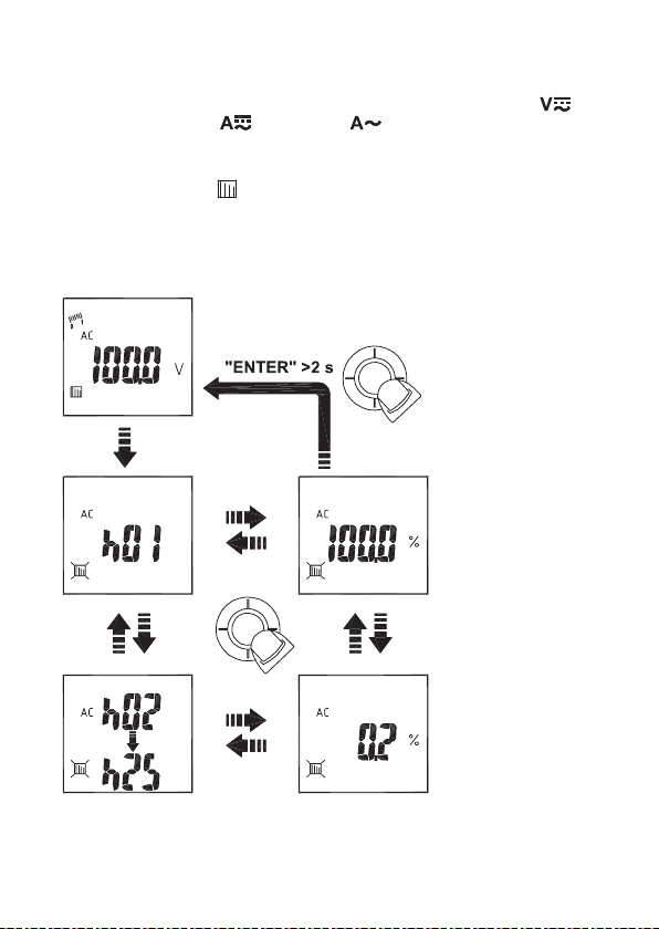
h) Distorsion harmonique (taux d’ondes harmoniques)
• Déplacez la molette de réglage (7) sur le symbole pour la mesure de la tension « »
ou la mesure du courant « » (VC732) ou « » (VC731). Observez également
les informations à propos de la mesure du tenson/courant dans le chapitre 11 c) et 11 j).
• Pour la mesure de la distorsion harmonique (uniquement possible en mode AC),
sélectionnez le symbole « » à l’aide du bouton de navigation (5). Validez la
sélection en appuyant sur le bouton de navigation (« ENTER »).
• Pour quitter ce mode, appuyez pendant au moins 2 secondes sur le bouton de
navigation (« ENTER »).
• La valeur s’affiche sur l’écran à cristaux liquides.
97
Page 98

i) Mesure des pointes de tension (« Peak »)
• Déplacez la molette de réglage (7) sur le symbole pour la mesure de la tension « ».
Observez les informations spécifiques à la mesure de la tension, chapitre 11 c).
• Pour la mesure de pointes de tension (uniquement possible en mode AC), sélectionnez
le symbole « » à l’aide du bouton de navigation (5). Validez la sélection en appuyant
sur le bouton de navigation (« ENTER »).
• Pour quitter ce mode, appuyez pendant au moins 2 secondes sur le bouton de
navigation (« ENTER »).
• La valeur s’affiche sur l’écran à cristaux liquides.
98
Page 99

j) Mesure du courant
• Déplacez la molette de réglage (7) sur le symbole pour la mesure du courant « »
(VC732) ou « » (VC731).
N’appliquez la pince ampèremétrique que sur un seul conducteur à la fois. Si
vous l’appliquez sur plusieurs conducteurs, vous n’obtiendrez pas de résultats
concluants.
En raison de l’effet magnétique continu du capteur de courant, un faible
courant peut s’afficher sur l’écran à cristaux liquides durant la mesure du
courant, même si la pince n’est pas appliquée sur un conducteur.
Pour mettre à « 0 » l’affichage (uniquement VC732), appuyez pendant au moins
¼
2 secondes sur la touche « HOLD ». L’affichage est remis à zéro.
• Si elles sont encore raccordées, retirez les
lignes de mesure de la pince
ampèremétrique avant la mesure du
courant.
• Sélectionnez la fonction « AC », « DC » ou
« AC+DC » (uniquement VC732) à l’aide du
bouton de navigation (5). Une tonalité
brève retentit. Validez la fonction souhaitée
en appuyant sur le bouton de navigation
(« ENTER »).
• Ouvrez le capteur de la pince
ampèremétrique (1) à l’aide du levier
d’ouverture (3). Appliquez la pince
ampèremétrique sur le conducteur à
mesurer puis refermez le capteur de la
pince ampèremétrique (1). Tant que le
capteur de la pince ampèremétrique est
ouvert, le champ d’action est éclairé par
une DEL.
• Le courant s’affiche sur l’écran à cristaux
liquides.
• Pour terminer la mesure, retirez le capteur
de la pince ampèremétrique (1) du
conducteur puis éteignez la pince
ampèremétrique. Pour ce faire, tournez la
molette de réglage (7) en position « OFF ».
99
Page 100

k) Mesure des pointes de courant (« Peak »)
• Déplacez la molette de réglage (7) sur le symbole pour la mesure du courant « »
(VC732) ou « » (VC731). Observez également les informations à propos de la
mesure du courant dans le chapitre 11 j).
• Pour la mesure de pointes de courant (uniquement possible en mode AC), sélectionnez
le symbole « » à l’aide du bouton de navigation (5). Validez la sélection en
appuyant sur le bouton de navigation (« ENTER ») pendant au moins 2 secondes.
L’indication « PEAK » s’affiche sur l’écran.
• Pour quitter ce mode, appuyez pendant au moins 2 secondes sur le bouton de
navigation (« ENTER »).
• La valeur s’affiche sur l’écran à cristaux liquides.
100
 Loading...