

Page 1

Digital Multimeters
■VC-7060BT
■VC-7200BT
Quick Guide
Page 2

General Warranty
We warrant that the product will be free from defects in materials and workmanship for a
period of 3 years (1 year for accessories) from the date of purchase of the product by the
original purchaser from our company. This warranty only applies to the original purchaser
and is not transferable to a third party.
If the product proves defective during the warranty period, we will either repair the
defective product without charge for parts and labour, or will provide a replacement in
exchange for the defective product. Parts, modules and replacement products used by our
company for warranty work may be new or reconditioned like new. All replaced parts,
modules and products become the property of our company.
In order to obtain service under this warranty, the customer must notify our company of
the defect before the expiration of the warranty period. Customer shall be responsible for
packaging and shipping the defective product to the designated service centre, a copy of
the customers proof of purchase is also required.
This warranty shall not apply to any defect, failure or damage caused by improper use or
improper or inadequate maintenance and care. We shall not be obligated to furnish service
under this warranty a) to repair damage resulting from attempts by personnel other than
our company representatives to install, repair or service the product; b) to repair damage
resulting from improper use or connection to incompatible equipment; c) to repair any
damage or malfunction caused by the use of not our supplies; or d) to service a product
that has been modified or integrated with other products when the effect of such
modification or integration increases the time or difficulty of servicing the product.
Please contact the nearest Sales and Service Offices for services.
Excepting the after-sales services provided in this summary or the applicable
warranty statements, we will not offer any guarantee for maintenance definitely
declared or hinted, including but not limited to the implied guarantee for
marketability and special-purpose acceptability. We should not take any
responsibilities for any indirect, special or consequent damages.
Page 3

i
Table of Contents
1.Safety Information ...................................................................................................... 1
Safety Terms and Symbols ..................................................................................................... 1
General Safety Requirements ................................................................................................ 2
Measurement Limits .............................................................................................................. 3
Main Input Terminals (HI Input and LO Input) Measurement Limits ....................................................... 3
Current Input Terminal (I) Measurement Limits ...................................................................................... 3
Sense Terminals (HI Sense and LO Sense) Measurement Limits .............................................................. 4
Measurement Category ......................................................................................................... 4
2.Quick Start .................................................................................................................. 5
General Inspection ................................................................................................................. 5
Dimensions ............................................................................................................................ 5
Foot Stool Adjustment ........................................................................................................... 6
Front Panel Overview ............................................................................................................ 6
Rear Panel Overview .............................................................................................................. 8
User Interface ........................................................................................................................ 9
Power On ............................................................................................................................. 10
Measurement Connections .................................................................................................. 10
Data Record Function .......................................................................................................... 12
Manual Record ....................................................................................................................................... 12
Auto Record ............................................................................................................................................ 13
Troubleshooting .................................................................................................................. 15
3.Appendix ................................................................................................................... 16
Appendix A: Enclosure ......................................................................................................... 16
Appendix B: General Care and Cleaning ............................................................................... 16
Appendix C: Line Fuse Replacement ..................................................................................... 17
Page 4
1.Safety Information
1
1. Safety Information
Safety Terms and Symbols
Safety Terms
Terms in this Manual. The following terms may appear in this manual:
Warning: Warning indicates the conditions or practices that could result in
injury or loss of life.
Caution: Caution indicates the conditions or practices that could result in
damage to this product or other property.
Terms on the Product. The following terms may appear on this product:
Danger: It indicates an injury or hazard may immediately happen.
Warning: It indicates an injury or hazard may be accessible potentially.
Caution: It indicates a potential damage to the instrument or other property might occur.
Safety Symbols
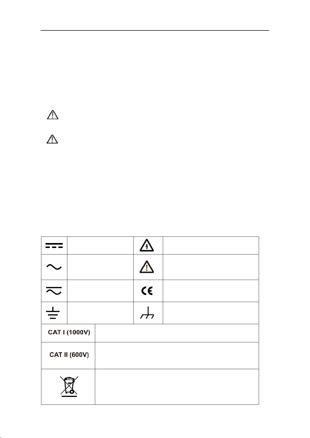
Symbols on the Product. The following symbol may appear on the product:
Direct current (DC)
Alternating current (AC)
Both direct and
alternating current
Ground terminal
Warning, risk of electric shock
Caution, risk of danger (refer to this
manual for specific Warning or
Caution information)
Conforms to European Union
directives
Chassis Ground
IEC Measurement Category I. The maximum measurable
voltage is 1000 Vpk in the HI -LO terminal.
IEC Measurement Category II. Inputs may be connected to AC
mains power (up to 600 VAC) under Category II overvoltage
conditions.
This product complies with the WEEE Directive (2012/19/EC)
marking equipment. The affixed product label indicates that
you must not discard this electrical/electronic product in
domestic household waste.
Page 5

1.Safety Information
2
General Safety Requirements
Before any operations, please read the following safety precautions to avoid any
possible bodily injury and prevent this product or any other products connected from
damage. In order to avoid any contingent danger, this product is only used within the
range specified.
Check AC power input setting according to the standards in your own country.
Use Proper Power Cord. Use only the power cord supplied with the product and
certified to use in your country.
Product Grounded. This instrument is grounded through the power cord grounding
conductor. To avoid electric shock, the grounding conductor must be grounded. The
product must be grounded properly before any connection with its input or output
terminal.
Limit operation to the specified measurement category, voltage, or amperage
ratings.
Check all Terminal Ratings. To avoid instrument damage and the risk of electric shock,
check all the Measurement Limits and markers of this product. Refer to the user's
manual for the Measurement Limits before connecting to the instrument. Do not
exceed any of the Measurement Limits defined in the following section.
Do not operate without covers. Do not operate the instrument with covers or panels
removed.
Use Proper Fuse. Use only the specified type and rating fuse for this instrument.
Avoid exposed circuit. Do not touch exposed junctions and components when the
instrument is powered.
Do not operate if in any doubt. If you suspect damage occurs to the instrument,
have it inspected by qualified service personnel before further operations.
Use your instrument in a well-ventilated area. Inadequate ventilation may cause
increasing of temperature or damages to the device. Please keep well ventilated and
inspect the intake regularly.
Do not operate in wet conditions. In order to avoid short circuiting to the interior of
the device or electric shock, please do not operate in a humid environment.
Do not operate in an explosive atmosphere.
Keep product surfaces clean and dry.
Only the qualified technicians can implement the maintenance.
Page 6
1.Safety Information
3
Measurement Limits
The protection circuitry of the multimeter can prevent damage to the instrument and
protect against the danger of electric shock, when the Measurement Limits are not
exceeded. To ensure safe operation of the instrument, do not exceed the Measurement
Limits shown on the front panel, it is defined as follows:
The user-replaceable 10 A current-protection fuse is on the front panel. To maintain
protection, replace fuse only with fuse of the specified type and rating. About the
specified type and rating of the fuse, please refer to "7 Current Terminal Fuse" in "Front
Panel Overview" on page 7.
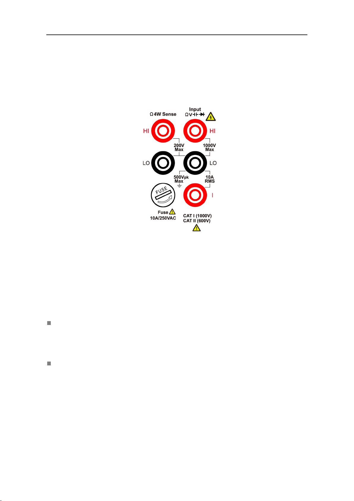
Main Input Terminals (HI Input and LO Input) Measurement Limits
The HI and LO input terminals are used for voltage, resistance, continuity, frequency
(period), capacitance, diode, and temperature test measurements. Two Measurement
Limits are defined for these terminals:
HI Input to LO Input Measurement Limit
The Measurement Limit from HI Input to LO Input is 1000 VDC or 750 VAC, which is
also the maximum voltage measurement. This limit can also be expressed as 1000
Vpk maximum.
LO Input to Ground Measurement Limit
The LO input terminal can safely "float" a maximum of 500 Vpk relative to ground,
where ground is defined as the Protective Earth Conductor in the AC mains power
cord connected to the instrument.
As implied by the above limits, the Measurement Limit for the HI input terminal is a
maximum of 1500 Vpk relative to ground when LO Input is at its maximum of 500 Vpk
relative to ground.
Current Input Terminal (I) Measurement Limits
The Measurement Limit from the current input terminal (I) to the LO Input terminal is 10
A (DC or AC). Note that the current input terminals will always be at approximately the
Page 7

1.Safety Information
4
same voltage as the LO Input terminal, unless a current protection fuse is open.
Sense Terminals (HI Sense and LO Sense) Measurement Limits
The HI and LO sense terminals are used for four-wire resistance measurements.
The Measurement Limit from HI Sense to LO Input is 200 Vpk.
The Measurement Limit from HI Sense to LO Sense is 200 Vpk.
The Measurement Limit from LO Sense to LO Input is 2 Vpk.
Note: The 200 Vpk limit on the sense terminals is the Measurement Limit. Operational
voltages in resistance measurements are much lower – up to ± 12 V in normal operation.
Measurement Category
The safety rating of the multimeter:
1000 V, CAT I
IEC Measurement Category I. The maximum measurable voltage is 1000 Vpk in the HI -LO
terminal.
600 V, CAT II
IEC Measurement Category II. Inputs may be connected to AC mains power (up to 600
VAC) under Category II overvoltage conditions.
Measurement category definition
Measurement CAT I applies to measurements performed on circuits not directly
connected to the AC mains. Examples are measurements on circuits not derived from the
AC mains and specially protected (internal) mains- derived circuits.
Measurement CAT II applies to protect against transients from energy-consuming
equipment supplied from the fixed installation, such as TVs, PCs, portable tools, and
other household circuits.
Measurement CAT III applies to protect against transients in equipment in fixed
equipment installations, such as distribution panels, feeders and short branch circuits,
and lighting systems in large buildings.
Measurement CAT IV applies to measurements performed at the source of the lowvoltage installation. Examples are electricity meters and measurements on primary over
current protection devices and ripple control units.
Page 8

2.Quick Start
5
235 mm
110 mm
2. Quick Start
General Inspection
After you get a new multimeter, it is recommended that you should make a check on the
instrument according to the following steps:
1. Check whether there is any damage caused by transportation.
If it is found that the packaging carton or the foamed plastic protection cushion has
suffered serious damage, do not throw it away first till the complete device and its
accessories succeed in the electrical and mechanical property tests.
2. Check the Accessories
The supplied accessories have been already described in the Appendix A: Enclosure
of this Manual. You can check whether there is any loss of accessories with reference
to this description. If it is found that there is any accessory lost or damaged, please
get in touch with our distributor responsible for this service or our local offices.
3. Check the Complete Instrument
If it is found that there is damage to the appearance of the instrument, or the
instrument cannot work normally, or fails in the performance test, please get in
touch with our distributor responsible for this business or our local offices. If there is
damage to the instrument caused by the transportation, please keep the package.
With the transportation department or our distributor responsible for this business
informed about it, a repairing or replacement of the instrument will be arranged by
us.
Dimensions
Page 9

2.Quick Start
6
295 mm
2
3
4
5
12
1
6
7
8
11
9
10
13
Item
Name
Description
1
LCD
Display the user interface
2
Menu selection
Keys
3
Operation Keys
Save
Collect data in manual record. The instrument saves
page 12, Manual Record.
(
VC-7200BT, for example)
Foot Stool Adjustment
Unfold the foot stool on the bottom of the multimeter.
Front Panel Overview
Figure 2-1 Front panel overview
Activate the corresponding menu
current reading each time the Save key is pressed. See
(VC-7060BT, for example)
Page 10

2.Quick Start
7
Record
Access menus of manual record and auto record.
See page 12, Data Record Function.
Run/Stop
When the trigger source is set as Auto, start or stop auto
, the instrument
issues one trigger each time this key is pressed.
Math
Perform math operations (statistic, limits, dB/dBm, REL) on
the measurement results.
Utility
Set the auxiliary system function, including Language,
LCD test, Key test.
Port
Set Serial, Trigger, Output connector, Net Type.
4
HI and LO Sense
Terminals
Signal input terminals, used for four-wire resistance
measurements.
5
HI and LO Input
Signal input terminals, used for voltage, resistance,
temperature test measurements.
6
Range/Direction Keys
When the Range softkey is shown on the right menu, you
7
Current Terminal
The rating is 10 A, 250 VAC.
clockwise to lock it in place.
8
AC/DC Current Input
Terminals
Signal input terminals, used for AC/DC current
measurements.
9
Power button
Turn on/off the multimeter.
trigger.
When the trigger source is set as Single
Backlight, Clock, SCPI, Set to default, System information,
Terminals
Fuse
continuity, frequency (period), capacitance, diode, and
can press the key to switch between auto and
manual range. Press to enable manual range, and
increase or decrease the measurement range.
When setting a parameter, press to move the cursor,
press to increase or decrease the value.
To replace the fuse:
Turn off the multimeter and remove the power cord. Use a
flat-blade screw driver to turn the fuse holder
counter-clockwise, and pull out the fuse holder. Put the
new specified fuse into the fuse holder, and insert the
assembly back into the instrument, turning the fuse holder
Page 11

2.Quick Start
8
10
Measurement
11
Graph
Choose what is displayed: number, bar meter, trend chart,
or histogram.
12
Dual
Press this key to display the function list on the right menu,
will be displayed in the Vice Display.
13
USB Connector
Connect with an external USB device, such as connect a
USB memory device to the instrument.
1
2
3
4
5
7
6
8
9
Item
Name
Description
1
External Trigger
Trigger the multimeter by connecting a trigger pulse. The
( → Trigger → Source (External) )
Function Keys
select a function, if the function is supported, the reading
Rear Panel Overview
DC or AC voltage measurements
DC or AC current measurements
Resistance, continuity, and diode measurements
Capacitance measurements
Frequency/Period measurements
Temperature measurements
Figure 2-2 Rear panel overview
Input
external trigger source must be selected.
Page 12

9
2
Auxiliary Output
Connector
Output → Output (P/F)).
3
RS232
Connect the PC through this interface.
4
USB (type B)
This can be used to connect a USB type B controller.
and controlled via PC software.
5
Local Area
Connector
The multimeter can be connected to the network for
6
Line Fuse
The fuse rating is 250 V, F 0.5AL. To repl a ce the fuse, see
7
AC Mains Input
AC mains input connector.
8
Chassis Ground
Screw
To ground the chassis.
9
Instrument Cable
You can lock the instrument to a fixed location using the
instrument.
Trigger Mode
Reading
Range Function
Operation Menus
Unit
Status Icon
2.Quick Start
Defaults to Voltmeter Measurement Complete Output,
outputs a pulse whenever the multimeter finishes taking a
measurement to allow you to signal other devices. This
connector can also be configured to output a pulse when
limits are exceeded in Math limits function ( →
Connector
Network (LAN)
Lock
User Interface
Connect with an external device, such as connected to a PC
remote control via this connector.
page 17, Appendix C: Line Fuse Replacement.
security lock (please buy it yourself) to secure the
Page 13

2.Quick Start
10
Secondary function reading
Primary function reading
Primary function
Trigger Mode
Status Icon
Display
Description
Icon
Description
Trigger Auto trigger
Ext Trigger External trigger
Figure 2-3 User interface (Single display)
LAN is connected
Connect as a slave device with PC
Auto record function is running
USB memory device is detected
Manual record
Figure 2-4 User interface (Dual display)
Power On
(1) Connect the instrument to the AC supply using the supplied power cord.
Warning:
To avoid electric shock, the instrument must be grounded properly.
(2) Press down the power button at the front panel, the screen shows the boot screen.
Measurement Connections
After selecting the desired measurement function, please connect the signal (device)
under test to the multimeter according to the method below. To avoid instrument
damage, do not discretionarily switch the measurement function when measuring.
Page 14

2.Quick Start
11
DC Voltage
AC Voltage
DC Current Measurement
DC Current
AC Current Measurement
AC Current
I
2-wire Resistance
I
4-wire Resistance
Open or Closed Circuit
I
Forward Bias
I
DC Voltage Measurement
AC Voltage Measurement
2-wire Resistance Measurement
Continuity Test
4-wire Resistance Measurement
Diode Measurement
Page 15

2.Quick Start
12
Capacitance
AC Signal
Temp Transducer
I
Capacitance Measurement
Temperature Measurement
Frequency/Period Measurement
Data Record Function
Data record function includes manual record and auto record. You can use any or both
functions to record the data.
Manual record: Press the front panel key to save current reading to internal
memory. The maximum number of readings is 1000. Once you have finished collecting
data, you can view it in table, and export it to external memory.
Auto record: After setting memory, number of readings, sample interval, press the Start
softkey to start recording. You can view the data in internal memory in table or graph.
Manual Record
1. Collect data: The instrument saves current reading in internal memory each time the
front panel key is pressed. The instrument beeps, and the icon will
show up on the top of the display.
Note: The measurement function can be switched during manual record. When the
dual display is enabled, both readings can be recorded.
2. View the manual record: Press the front panel key, press the Manual record
softkey to display the data table. Press keys to turn the page. (When the data
table is shown, you can still save current reading by pressing the key.)
Note:
When the recording data exceeds the current range, the data will be marked as
Page 16

2.Quick Start
13
"overload".
"rel" in the table indicates the relative operation is turned on.
3. Export to USB memory: Connect a USB memory to the front panel USB connector.
Press the Export softkey to export the manual record in internal memory to USB
memory as a CSV file. The file will be saved in \Record\Manual folder in USB memory.
The file name is Data_YYYYMMDD_HHMMSS, YYYYMMDD is the data recording start
date, HHMMSS is the start time, e.g. Data_20160804_095622.csv.
4. Clear the manual record: Press the Clear softkey to clear current manual record.
Auto Record
1. Configure the parameters: Press the front panel key, press the Auto record
softkey.
Press the Memory softkey to select internal or external memory
Press the Points softkey to specify the total number of readings to record. The range
is 1 to 1 M for internal memory, 1 to 100 M for external memory.
Press the Interval softkey to specify the time interval between readings. The range is
5 ms to 1000 s.
2. Record data: Press the Start softkey to start auto record. The icon will show up
on the top of the display. Press the Stop softkey to stop recording, the data will be
saved in the specified memory as a CSV file. If the external memory is selected, the
file will be saved in \Record\Auto folder in USB memory. The file name is
Data_YYYYMMDD_HHMMSS, YYYYMMDD is the data recording start date, HHMMSS
is the start time, e.g. Data_20160804_095622.csv.
Note:
When the auto recording mode is running, press another measurement function
key, the instrument will display a message "Press the key again to switch function
and stop recording.".
If you want to continue auto recording, just wait until the message disappears.
If you want to stop auto recording and switch to the function, press the function
key again when the message is still displayed. The recording data before switching
the function will be saved.
In auto range, the relay switch may cause jitter, the data at this time is invalid. It
Page 17

2.Quick Start
14
will last about a few hundred milliseconds, and the data acquired in this period will
be marked as "invalid".
When the dual display is enabled, only the reading of main display function can be
saved.
3. Read and view the auto recording file: Press the front panel key, press the
View record softkey.
Memory can only be internal me mory.
Press the Display softkey to select Ta b l e or Graph to display the readings.
Press the Read softkey to read and view the auto record file in the internal memory.
(If the data is viewed in table, press keys to turn the page.)
Auto recording data displayed in graph
Auto recording data displayed in table
Page 18

2.Quick Start
15
Troubleshooting
1. The instrument is powered on but no Display.
1) Check if the power is connected properly.
2) Check if the line fuse which is below the AC Mains Input is used appropriately and
in good condition (see page 17, Appendix C: Line Fuse Replacement).
3) Restart the instrument after the steps above.
4) If the problem still exists, please contact us for our service.
2. The reading does not change when a current signal is input.
1) Check whether the test lead is correctly inserted into the current input terminals
(I terminal and LO Input terminal).
2) Check whether the current terminal fuse at the front panel is burned out.
Please refer to "7 Current Terminal Fuse" in "Front panel overview" on page 7.
3) Check whether the DCI or ACI measurement function is enabled.
4) Check whether the DCI measurement function is used to measure AC current.
If you encounter other problems, try to reset the settings or restart the instrument. If it
still cannot work properly, please contact us for our service, and provide your device
information. ( → Next → System Info)
Page 19

3.Appendix
16
Quick Guide
Safety Hintsheet
Software CD
Warn
instrument has already been dried completely, avoiding any
3. Appendix
Appendix A: Enclosure
Standard Accessories (subject to final delivery):
USB Cable
Spare Fuses
Power Cord
Test Leads
Crocodile Clips
Appendix B: General Care and Cleaning
General Care
Do not store or leave the instrument where the liquid crystal display will be exposed
to direct sunlight for long periods of time.
Cleaning
To clean the instrument exterior, perform the following steps:
1. To prevent electrical shock, disconnect the instrument from AC mains power
and disconnect all test leads before cleaning.
2. Clean the outside of the instrument using a wet soft cloth not dripping water. Do
not make any scuffing when cleaning the LCD screen. To avoid damage to the
instrument, do not use any corrosive chemical cleaning agent.
Caution: To avoid any damage to the instrument, do not exposed it to any sprays,
liquids, or solvents.
ing: Before power on again for operation, it is required to confirm that
the
electrical short circuit or bodily injury resulting from the moisture.
Page 20

3.Appendix
17
Warning: Disconnect the line cord at the rear panel and remove all test leads
result in personal injury or death.
200 - 240 V AC
250 V, F0.5AL
Appendix C: Line Fuse Replacement
The line fuse is in the plastic fuse box below the power line input on the rear panel.
connected to the instrument before replacing the line fuse. Failure
to do so could expose the operator to hazardous voltages that could
Use only the correct fuse type. Failure to do so could result in personal injury or
instrument damage.
Voltage Fuse
To perform the line fuse replacement, follow these steps:
1. Turn off the multimeter, remove all measurement leads and other cables from the
instrument, including the power cord.
2. Use a flat-blade screwdriver to remove the fuse box.
3. Replace the fuse with a new one, which should match with the voltage; install it into
the fuse box, and push the fuse box back on to the rear panel.
2019.08 V1.0.1
 Loading...