

Quick Guide
10
3
5 4
9
8
1
6
2
7
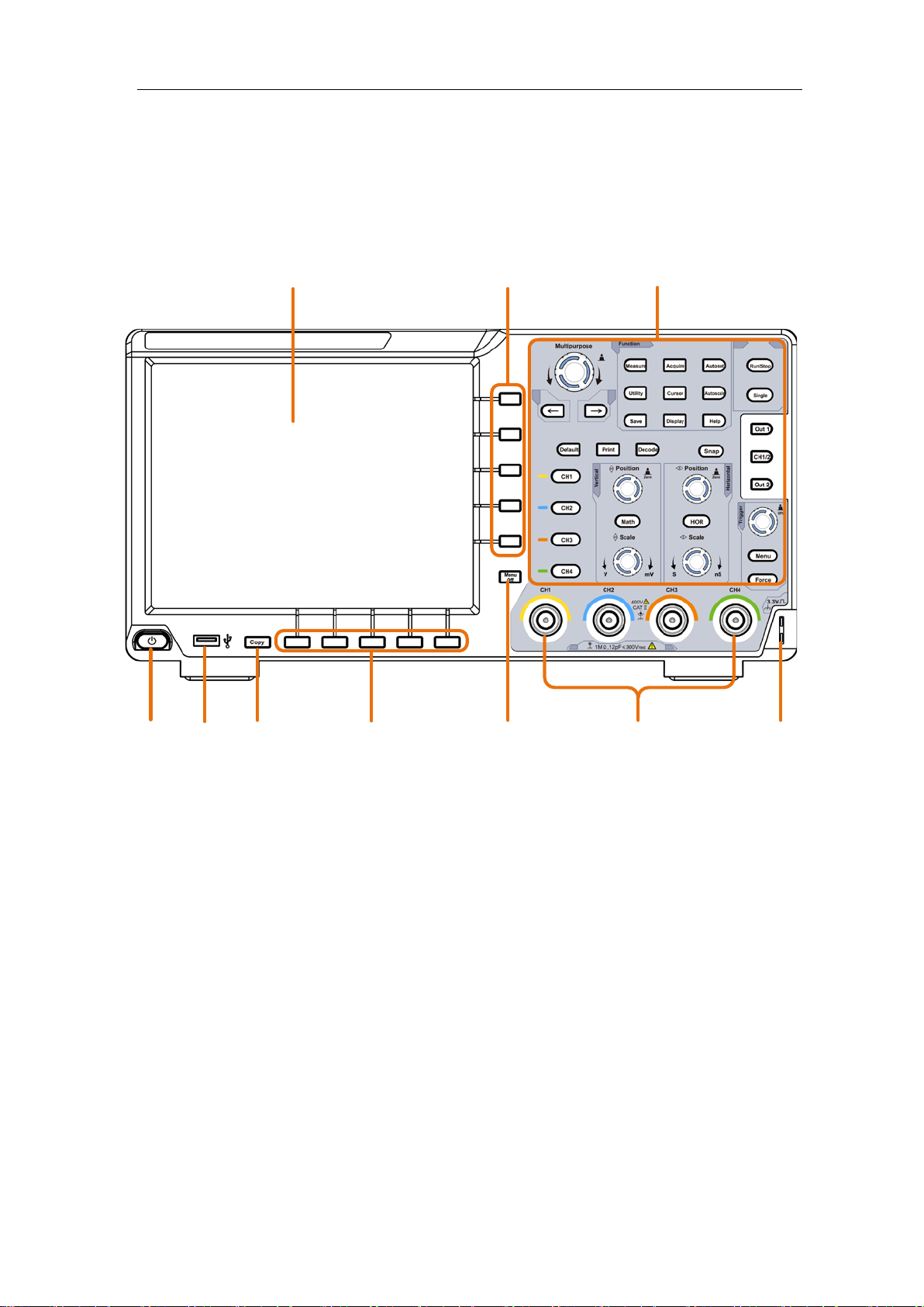
Front Panel
Quick Guide
1. Display area
2. Select the right menu item
3. Control (button and knob) area
4. Probe Compensation: Measurement signal ( ≈ 3.3V/1kHz) output.
5. Input connectors of four channels
6. Remove the left and right menu
7. Select the bottom menu item
8. Copy button: You can save the waveform by just pressing this button in any user
interface.
9. USB Host port: It is used to transfer data when external USB equipment connects to
the oscilloscope regarded as "host device". For example: Saving the waveform to
USB flash disk needs to use this port.
10. Power on/off
1
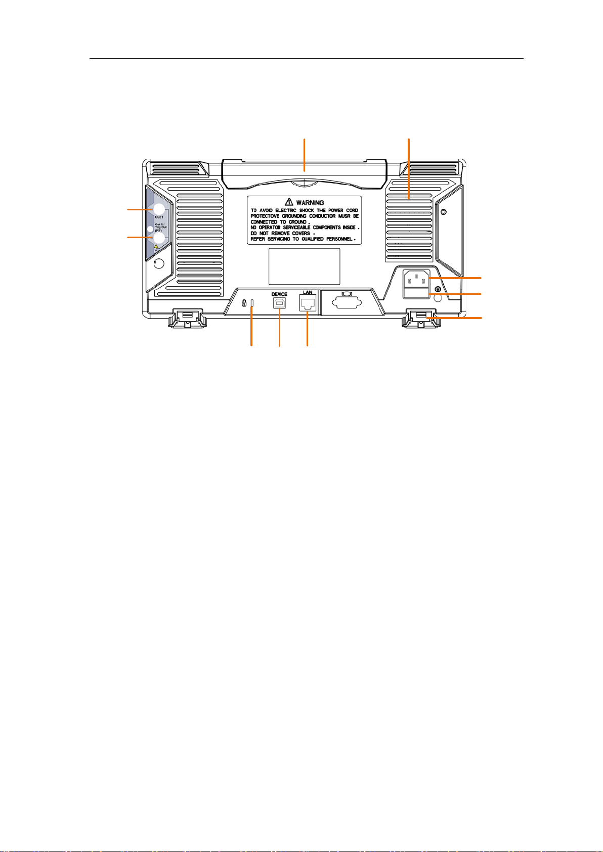
Rear Panel
8
7
6
10
9
1 2
5
3
4
Quick Guide
1. Handle
2. Air vents
3. AC power input jack
4. Fuse
5. Foot stool: Adjust the tilt angle of the oscilloscope.
6. LAN port: the network port which can be used to connect with PC.
7. USB Device port: It is used to transfer data wh en external USB equipment connects to
the oscilloscope regarded as "slave device". For example: to use this port when
connect PC to the oscilloscope by USB.
8. Lock Hol e: You can lock the oscilloscope to a fixed location using the security lock
(please buy it yourself) to secure the oscilloscope.
9. Trig Out(P/F) port: Trigger signal output or Pass/Fail output, als o can be used as the
port of CH2 Output of optional dual-channel waveform generator. The output type can
be set in the menu (Utility menu→Output→Output).
10. Out 1 port: Output (single-channel) or CH1 Output (dual-channel) of optional
waveform generator.
2
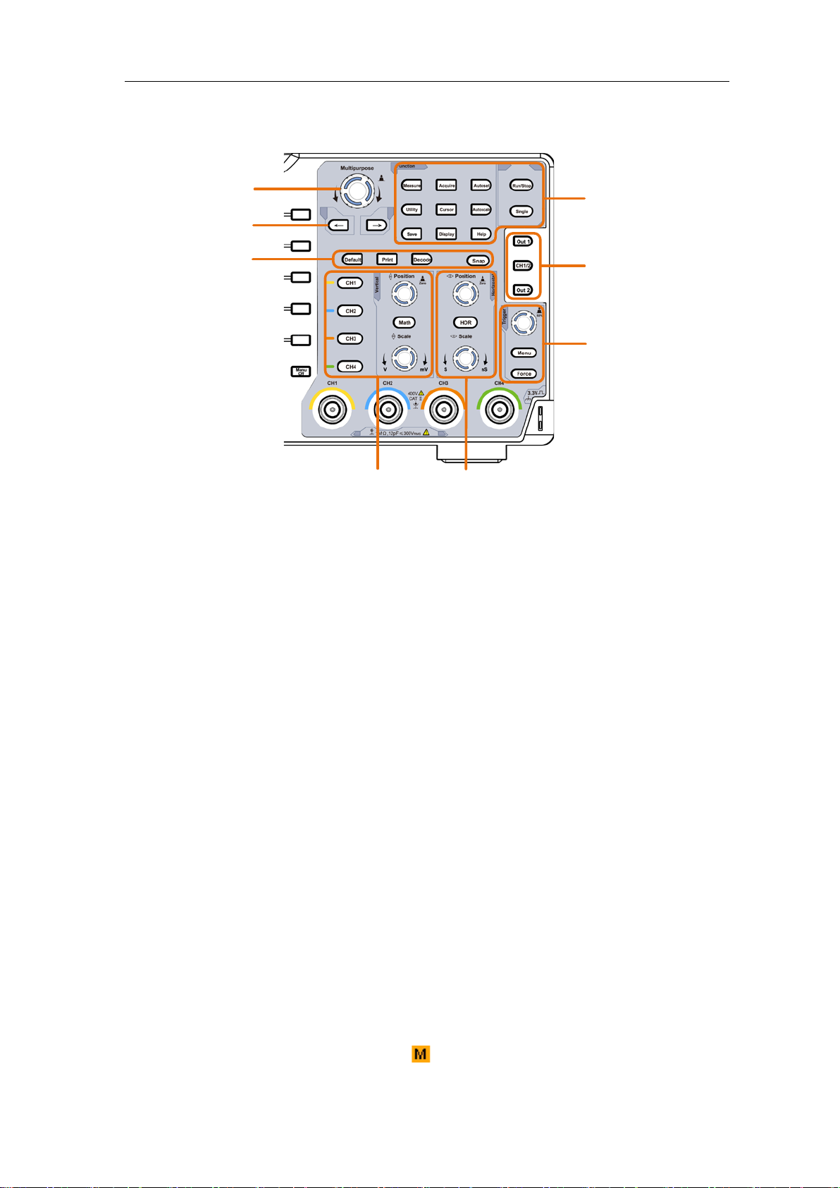
Control Area
1
2
3
8
7
5
4
6
Quick Guide
1. Function button area: Total 11 buttons
2. Waveform generator controls (optional)
or
DAQ: This function is not available.
P/F: Pass/Fail
W.REC: Waveform Record
3. Trigger control area with 2 buttons and 1 knob.
The Trigger Level knob is to adjust trigger voltage. Other 2 buttons refer to trigger
system setting.
4. Horizontal control area with 1 button and 2 knobs.
"HOR" button refer to horizontal system setting menu, "Horizontal Position" knob
control trigger position, "Horizontal Scale" control time base.
5. Vertical control area with 5 buttons and 2 knobs.
CH1 - CH4 buttons correspond to setting menu in CH1 - CH4. "Math" button
provides access to math waveform functions (+, -, ×, /, FFT, user function, digital
filter). The "Vertical Position" knob control the vertical position of current chann el,
and the "Scale" knob control voltage scale of current channel.
6. Default: Call out the factory settings.
Print: Print an image of what appears on the instrument screen.
Decode: Turn on/off Decode function.
Snap: Shortcut button for measurement snapshot.
7. Direction key: Move the cursor of the focused parameter.
8. M knob (Multipurpose knob): when a symbol appears on the menu, it indicates
you can turn the M knob to select the menu or set the value. You can push it to close
3

Quick Guide
1
3
9
19
13
27
24
6
8
10
11
14
15
20
22
28
30
7
25
2
4
5
23
12
5
18
29
16
17
21
26
the menu on the left and right.
User Interface Introduction
1. Waveform Display Area.
2. Run/Stop (touchable)
3. The state of trigger, including:
Auto: Automatic mode and acquire waveform without triggering.
Trig: Trigger detected and acquire waveform.
Ready: Pre-triggered data captured and ready for a trigger.
Scan: Capture and display the waveform continuously.
Stop: Data acquisition stopped.
4. Click to auto set.
5. The two blue dotted lines indicates the vertical position of cursor measurement.
6. The pointer indicates the trigger position in the record length.
7. The T pointer indicates the horizontal position for the trigger.
8. It shows present triggering value and displays the site of present window in
internal memory.
9. Touchable icon is to enable (
10. It shows setting time.
11. It indicates that there is a USB disk connecting with the oscilloscope.
) or disable (
4
) the touchscreen controls.

Quick Guide
12. The waveform of CH1.
13. The pointer shows the trigger level position of the source in trigger menu.
14. The two blue dotted lines indicate the horizontal position of cursor measurement.
15. The waveform of CH2.
16. The waveform of CH3.
17. The waveform of CH4.
18. The frequency of the trigger signal.
19. The icon shows the selected trigger type, e.g. represents triggering on the
rising e dge for an Edge trigger. The reading shows the trigger level value of the
corresponding channel.
20. Click to show/hide the touchable shortcut menu.
21. It indicates the measured type and value of the corresponding channel. "T" means
period, "F" means frequency, "V" means the average value, "Vp" the peak-peak
value, "Vr" the root-mean-square value, "Ma" the maximum amplitude value,
"Mi" the minimum amplitude value, "Vt" the Voltage value of the waveform's
flat top value, "Vb" the Voltage value of the waveform's flat base, "Va" the
amplitude value, "Os" the overshoot value, "Ps" the Preshoot value, "RT" the rise
time value, "FT" the fall time value, "PW" the +width value, "NW" the -Width
value, "+D" the +Duty value, "-D" the -Duty value, "PD" the Delay A->B
value, "ND" the Delay A->B value, "TR" the Cycle RMS, "CR" the Cursor
RMS, "WP" the Screen Duty, "RP" the Phase A->B , "FP" the Phas e A->B ,
"+PC" the + Pulse count, "-PC" the - Pulse count, "+E" the R ise ed ge cou nt , "-E"
the Fall edge count, "AR" the Area, "CA" the Cycle area.
22. The readings show the record length.
23. The readings show current sample rate.
24. The readings indicate the corresponding Voltage Division of the channels.
"BW" indicates bandwidth limit.
The icon shows the coupling mode of the channel.
"—" indicates direct current coupling
"~" indicates AC coupling
" " indicates GND coupling
25. The reading shows the setting of main time base.
26. The green pointer indicates the grounding datum point (zero point position) of the
waveform of the CH1 channel.
27. The orange pointer indicates the grounding datum point (zero point position) of
the waveform of the CH1 channel.
28. It is cursor measure window, showing the absolute values and the readings of the
cursors.
29. The blue pointer indicates the grounding datum point (zero point position) of the
waveform of the CH1 channel.
30. The yellow pointer indicates the grounding datum point (zero point posi tion) of
the waveform of the CH1 channel.
5

Technical Specifications
Performance
Characteristics
Vertical Resolution
(A/D)
*
Dual CH*
Line/field frequency
(Video)
Technical Specifications
Oscilloscope
8 bits
DSO-6084 80 MHz
Bandwidth
Rise time
Horizontal Scale
Sample rate
(real time)
Waveform Refresh
Rate
Display
Channel
Record length
Input coupling
Input impedance
Max. input voltage
DC gain accuracy
Vertical sensitivity
Trigger type
Decoding Type
Trigger mode
DSO-6104 100 MHz
DSO-6204 200 MHz
DSO-6084 ≤ 4.375 ns
DSO-6104 ≤ 3.5 ns
DSO-6204 ≤ 1.75 ns
DSO-6084
DSO-6104
DSO-6204 1ns/div - 1000s/div, step by 1 – 2 - 5
DSO-6084
DSO-6104
DSO-6204
DSO-6084
DSO-6104
DSO-6204 70,000 wfms/s
8" color LCD, TFT display , 800×600 pixels
4
4 channels ON: max 10M;
2 channels ON: max 20M;
1 channel ON: max 40M.
DC, AC , Ground
1MΩ±2%,in parallel with 15pF±5pF
400 V (DC + AC Peak)
DSO-6084
DSO-6104
DSO-6204
1 mV/div-10 V/div
Edge, Video, Pulse, Slope, Runt, Windows, Timeout, Nth Edge, Logic, I2C,
SPI, RS232, CAN
RS232, I2C, SPI, CAN
Auto, Normal, Single
2ns/div - 1000s/div, step by 1 – 2 - 5
Four CH 250 MSa/s
Dual CH
Single CH 1 GSa/s
Four CH 500 MSa/s
Single CH 1 GSa/s
45,000 wfms/s
1 mV ±4%
≥2 mV ±3%
1 mV ±3%
≥2 mV ±2%
Instruction
500 MSa/s
1 GSa/s
Support standard NTSC, PAL and SECAM broadcast systems
6

Automatic
Rise Edge Count, Fall Edge Count, Area, and Cycle Area.
, ×, ÷, FFT, FFTrms, Intg, D iff, Sqrt, U ser D efine d Funct ion, digit al filt er
Communication
interface
simultaneously.
measurement
Technical Specifications
Period, Frequency, Mean, PK-PK, RMS, Max, Min, Top, Base, Amplitude,
Overshoot, Preshoot, Rise Time, Fall Time, +Pulse Width, -Pulse Width,
+Duty Cycle , -Duty Cycle, Delay A→B
Cursor RMS, Screen Duty, Phase, +Pulse Count, -Pulse Count,
, Delay A→B
Cycle RMS,
,
Waveform Math
Waveform storage
Power supply
Power Consumption
+, -
(low pass, high pass, band pass, band reject)
100 waveforms
USB, USB flash disk storage, Trig Out(P/F), LAN,
100V - 240 VACRMS, 50/60 Hz, CAT Ⅱ
DSO-6084
DSO-6104
DSO-6204 <24 W
<15 W
* For DSO-6084 and DSO-6104, M ax S ample rate (r eal tim e) f or Dual CH should meet eith er follow ing
condition:
1. CH1&CH2 on, CH3&CH4 off;
2. CH1&CH2 off, CH3&CH4 on.
For DSO-6204, Max Sample rate (real time) for Dual CH should meet the following condition:
CH1 and CH2 can not be turned on simultaneously, CH3 and CH4 can not be turned on
Waveform Generator (Optional)
Max Frequency
Output
Channel
Vertical Resolution
Amplitude Range
Waveform length
Standard Waveforms
25 MHz (Sample 125 MS/s)
1 or 2
14 bits
2 mVpp - 6 Vpp
8K
Sine, Square, Ramp, and Pulse
7
 Loading...