

Page 1

DSO1000E/SE/F Series
Digital Storage Oscilloscope
User Manual
(Version 1.4)
Page 2

Copyright Decl aration
All rights reserved; no part of this document may be reproduced or transmitted in any
form or by any means, electronic or mechanical, without prior written permission from
our company.
Our company reserves all rights to modify this document without prior notice. Please
contact our company for the latest version of this document before placing an order.
Our company has made every effort to ensure the accuracy of this document but does
not guarantee the absence of errors. Moreover, Our company assumes no
responsibility in obtaining permission and authorization of any third party patent,
copyright or product involved in relation to the use of this document.
Digital Storage Oscilloscope I
Page 3

General Safety Summary
Read the following safety precautions to avoid injury and prevent damage to this
product or any products connected to it. To evade potential hazards, use this product
only as specified.
Only qualified personnel should perform maintenance.
Avoid fire or personal injury.
Use suitable power cord. Use only the power cord specified for this product and
certified for the country of use.
Connect and disconnect properly. Connect a probe with the oscillosc ope before it is
connected to measured circuits; disconnect the probe from the oscilloscope after it is
disconnected from measured circuits.
Ground the product. This product is grounded through the grounding conductor of the
power cord. To avoid electric shock, the grounding conductor must be connected to
earth ground. Before making connections to the input or output terminals of the product,
ensure that the product is properly grounded.
Connect the probe in a r igh t way. The probe ground lead is at ground potential. Do
not connect the ground lead to an elevated voltage.
Check all terminal ratings. To avoid fire or shock hazard, check all ratings and
markings on the product. Refer to the product manual for detailed information about
ratings before making connections to the product.
Do not operate without covers. Do not operate this product with covers or panels
removed.
Avoid exposed circuitry. Do not touch exposed connections and components when
power is present.
Do not operate with suspected failures. If you suspect there is damage to this
product, have it inspected by qualified service personnel.
Assure good ventilation.
Do not operate in wet/damp environments.
Do not operate in an explosive atmosphere.
Keep product surfaces clean and dry.
Digital Storage Oscilloscope II
Page 4

Safety Terms and Symbols
Terms on the product. The following terms may appear on the product:
Danger It represents that harms may be caused to you at once if you perfor m the
operation.
Warning It represents that latent harms may be caused to you if you perform the
operation.
Notice It represents the damage possibly caused to the product or other
properties if you perform the operation.
Characters on the product. The following characters may appear on the product:
Notice
Please read
the manual
Protective
ground terminal
Measuring
ground terminal
Chassis
ground terminal
Product Scrapping
Device Recycling
We need extract and utilize natural resources to produce this device. If you do not
reclaim the device in a proper way, some substances it contains may become harmful
or poisonous to environments or human bodies. To avoid them being released outside
and to minimize the waste of natural resources, we suggest you reasonably call back
this device to ensure proper recovery and recycling of most materials within it.
Digital Storage Oscilloscope III
Page 5

Brief Introduction to the Series of digital storage oscilloscope
DSO1000E/F Series osc illoscopes cover t he bandwidths from 80MHz t o 250MHz, and
provide the real-time up to 1GSa/s. In addition, they have 7 inch color TFT LCD as well
as WINDOWS-style interfaces and menus for easy operation.
What’s more, the plenty menu information and the easy-to-operate buttons allow you to
gain information as much as possible in measurement; the multifunctional knobs and
the powerful shortcut keys help you save a lot of time in operation; the Auto Scale
function lets you detect sine and square waves automatically; By using the three
methods the oscilloscope provides (context-sensitive, hyperlinks, and an index), you
may master all operations on the device in quite a short time so as to greatly improve
your efficiency in production and development.
Model Channels Bandwidth Sample Rate AFG
DSO-1084E
DSO-1104E
DSO-1204E
DSO-1254E
DSO-1204E SE
DSO-1084F
DSO-1104F
DSO-1204F
DSO-1254F
4 80MHz 1GS/s 4 100MHz 1GS/s 4 200MHz 1GS/s 4 250MHz 1GS/s 4 200MHz 1GS/s 4 80MHz 1GS/s Yes
4 100MHz 1GS/s Yes
4 200MHz 1GS/s Yes
4 250MHz 1GS/s Yes
Digital Storage Oscilloscope IV
Page 6

Contents
Copyright Declaration ................................................................................................ I
General Safety Summary ....................................................................................... II
Safety Terms and Symbols .................................................................................... III
Product Scrapping ................................................................................................. III
Brief Introduction to the Series of digital storage oscilloscope ............................... IV
Contents ................................................................................................................... V
Chapter 1 Introduction ........................................................................................ 1
1.1 General Inspection ................................................................................... 2
1.2 Prepare Instrument for Use ....................................................................... 3
1.3 Accidence of the user interface ................................................................. 4
1.4 Functional Check ...................................................................................... 5
1.4.1 Connect the oscilloscope ...................................................................... 5
1.4.2 Observe the waveform ......................................................................... 5
1.5 Probe Introduction .................................................................................... 6
1.5.1 Safety ................................................................................................... 6
1.5.2 Probe Check Wizard ............................................................................. 6
1.5.3 Manual Probe Compensation ............................................................... 6
1.5.4 Probe Attenuation Setting ..................................................................... 7
Chapter 2 Function Introduction ........................................................................ 9
2.1 Menu and Control Keys .......................................................................... 10
2.2 Connector ............................................................................................... 11
2.3 Universal Knobs and Softkeys ................................................................ 11
2.4 Oscilloscope Setup ................................................................................. 12
2.5 Horizontal Controls ................................................................................. 13
2.6 Vertical System ....................................................................................... 14
2.6.1 Vertical Controls ................................................................................. 14
Digital Storage Oscilloscope V
Page 7

2.6.2 Math Operation ................................................................................... 16
2.7 Trigger System ....................................................................................... 20
2.7.1 Edge Trigger ....................................................................................... 22
2.7.2 Pulse Trigger ...................................................................................... 22
2.7.3 Video Trigger ...................................................................................... 24
2.7.4 Slope Trigger ...................................................................................... 25
2.7.5 Overtime Trigger ................................................................................. 26
2.7.6 Window Trigger .................................................................................. 27
2.7.7 Pattern Trigger .................................................................................... 28
2.7.8 Interval Trigger ................................................................................... 29
2.7.9 Under Amp Trigger ............................................................................. 30
2.7.10 UART Trigger ..................................................................................... 31
2.7.11 LIN Trigger ......................................................................................... 35
2.7.12 CAN Trigger ....................................................................................... 37
2.7.13 SPI Trigger ......................................................................................... 40
2.7.14 IIC Trigger .......................................................................................... 43
2.8 Save/Recall ............................................................................................ 47
2.8.1 Internal Save and Recall ..................................................................... 47
2.8.2 External save and recall ..................................................................... 48
2.9 Measure System ..................................................................................... 49
2.9.1 Scale measurement ............................................................................ 49
2.9.2 Cursor measurement .......................................................................... 50
2.9.3 Automatic Measurement ..................................................................... 51
2.10 Acquire ................................................................................................... 55
2.10.1 XY Mode ............................................................................................ 58
2.10.2 Roll Mode ........................................................................................... 58
2.11 Display ................................................................................................... 58
2.12 Utility System .......................................................................................... 59
2.12.1 Update Firmware ................................................................................ 60
2.12.2 Self Calibration ................................................................................... 60
2.12.3 Pass/Fail ............................................................................................ 61
2.13 Fast Action Buttons ................................................................................. 62
Digital Storage Oscilloscope VI
Page 8

2.13.1 AUTO SCALE ..................................................................................... 62
2.13.2 Default Setup...................................................................................... 64
Chapter 3 Waveform Generator ........................................................................ 67
3.1 Set Wave Type and Parameters ............................................................. 68
3.2 Edit Arbitrary Waveform .......................................................................... 69
3.3 Output Arbitrary Waveform...................................................................... 71
Chapter 4 Troubleshooting ............................................................................... 72
4.1 Problem Settlement ................................................................................ 72
Chapter 5 General Care and Cleaning ............................................................. 74
5.1 General Care .......................................................................................... 74
5.2 Cleaning ................................................................................................. 74
Appendix A: Tec hnical Specifications ................................................................... 75
Appendix B: Accessories ....................................................................................... 82
Appendix C Harmful and Poisonous Substances or Elements ............................ 83
Appendix D To replace the fuse ............................................................................. 84
Appendix E Open Source Information ................................................................ 86
Digital Storage Oscilloscope VII
Page 9

Chapter 1 Introduction
General Inspection
Prepare Instrument for Use
Accidence of the user interface
Functional Check
Probe Introduction
Digital Storage Oscilloscope 1
Page 10

1.1 General Inspection
Please check the instrument as following steps after receiving an oscilloscope:
Check the shipping container for damage:
Keep the damaged shipping container or cushioning material until the contents of
the shipment have been checked for completeness and the instrument has been
checked mechanically and electrically.
Check the accessories:
Accessories supplied with the instrument are listed in "Accesso r i es " in t h is manual.
If the contents are incomplete or damaged, please notify the franchiser.
Check the instrument:
In case there is any mechanical damage or defect, or the instrument does not
operate properly or fails performance tests, please notify the franchiser.
Digital Storage Oscilloscope 2
Page 11

1.2 Prepare Instrument for Use
Adjust the Supporting Legs
Adjust the supporting legs properly to use them as stands to tilt the oscilloscope
upwards for stable placement of the oscilloscope as well as better operation and
observation.
Connect the power cord as desired. Turn the instrument on by pressing the power
switch in the lower left corner of front panel.
If the instrument does not turn on, verify that the power cord is firmly connected
(power-line voltage is automatically sensed at power-on). Also make sure that the
instrument is connected to an energized power source.
Power Switch:
To turn off the instrument, please press power switch.
Digital Storage Oscilloscope 3
Page 12
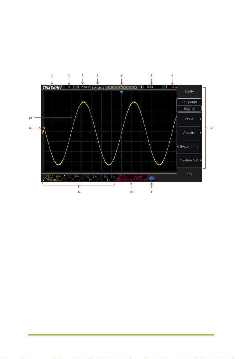
1.3 Accidence of the user interface
This section will make you understand the front operation panel of this series of digital
oscilloscope at first before use.
Figure 1-2 Interface display
1. Voltcraft logo
2. Trigger Status
Auto: The oscill oscope works in auto mode and is acquiring waveforms in the
absence of triggers.
Ready: All pre-triggered data have been acquired and the oscilloscope is ready to
accept a trigger.
Roll: The oscilloscope is acquiring and displaying waveform data continuously in
roll mode.
Stop: The oscilloscope has stopped acquiring waveform data.
3. Readout shows main time base setting.
4. Sample rate.
5. Main Time Base Window
Digital Storage Oscilloscope 4
Page 13
CH1: to connect with the probe
PROBE COMP
6. Tigger time
7. Trigger level, Readout tells trigger level.
8. Operating Menu shows different information for respective function keys.
9. If this icon lights up/active, it means the USB disk has been connected.
10. If this icon lights up/active, it means the wave generator works
11. The inf orm ation of coupling, B andwidth and volt/ di v of CH1~CH4.
12. Channel Marker
13. Window displays waveform.
1.4 Functional Check
Follow the steps below to perform a quick functional check to your oscilloscope.
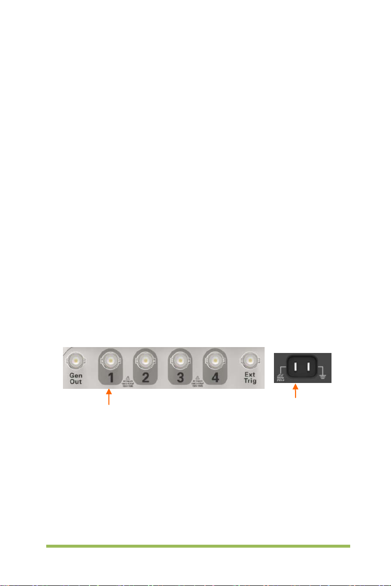
1.4.1 Connect the oscilloscope
Set the switch on the probe to 10X and connect the probe to Channel 1 on the
oscilloscope. First, align the slot in the probe connector with the protuberance on the
CH1 BNC and push to c onnect; then, turn to right to lock the probe in place; aft er t hat,
connect the probe tip and reference lead to the PROBE COMP connectors. The r e i s a
mark on the panel: Probe COMP ~2V@1KHz.
1.4.2 Observe the waveform
Press the [Auto Scale] button and y ou should see within a few seconds a square wave
of about 2V peak-to-peak at 1KHz in the display. Press the [CH1] MENU button twice
to remove Channel 1. Push the [CH2] MENU button and repeat the st eps to observe
CH2, CH3 and CH4.
Digital Storage Oscilloscope 5
Page 14
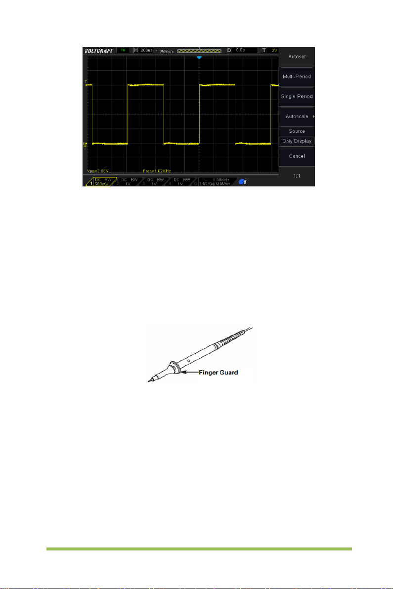
1.5 Probe Introduction
1.5.1 Safety
When using the probe, keep your fingers behind the guard on the probe body to avoid
electric shock. Do not touch metallic portions of the probe head while it is connect ed to
a voltage source. Connect the probe to the oscilloscope and connect the ground
terminal to ground before you start any measurements.
1.5.2 Probe Check Wizard
Every time you connect a probe to an input channel, you s hould use the probe check
wizard to verify that this probe is operating correctly.
Use the vertical menu (for example, push the [CH1] MENU button) to set the Probe
attenuation factor.
1.5.3 Manual Probe Compensation
Upon the first connection of a probe and an input channel, you should manually
perform this adjustment to match the probe to the input channel. Uncompensated or
Digital Storage Oscilloscope 6
Page 15
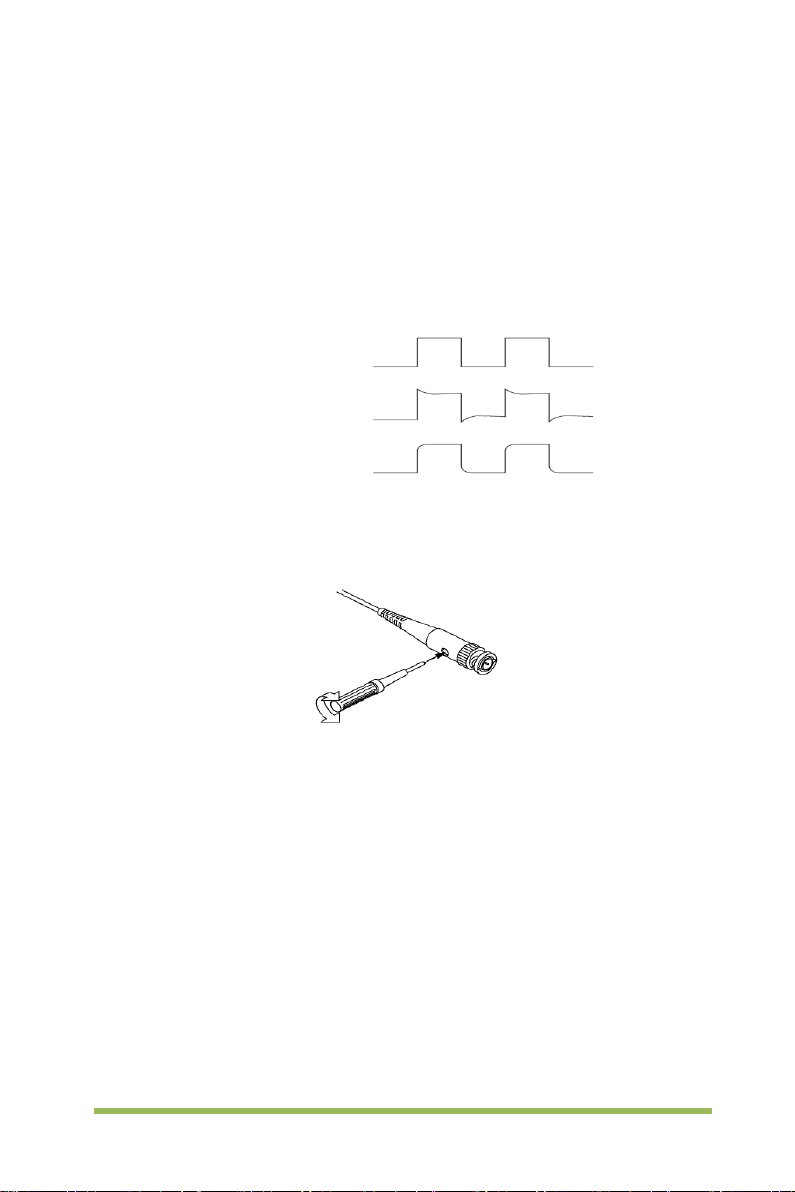
Compensated correctly
Undercompensated
miscompensated probes may lead to errors or faults i n measurement. To adjust the
probe compensation, follow the steps below.
1. Set the Probe option attenuation in the channel menu to 10X. Set the switch on the
probe to 10X and connect the probe to Channel 1 on the oscilloscope. If you use the
probe hook-tip, ensure it is firmly inserted onto the probe. Attach the probe tip to the
PROBE COMP ~2V@1KHz connector and the reference lead to the PROBE COM P
Ground connector. Display the channel and then press the Auto Scale button.
2. Check the shape of the displayed waveform.
Overcompensated
3. If necessary, use a nonmetallic screwdriver to adjust the variable capacity of your
probe until the shape of the waveform turns to be t he same as the above figure.
Repeat this step as necessary. See the figure below for the way of adjustment.
1.5.4 Probe Attenuati on Setting
Probes are of various attenuation factors which affect the vertical scale of the signal.
The Probe Check function is used to verify if t he P robe attenuation option matches the
attenuation of the probe.
You can push a vertical menu button (such as the CH1 MENU button) and select the
Probe option that matches the attenuation factor of your probe.
Make sure that the Attenuation switch on the probe matches the Probe opti on in the
oscilloscope. Switch settings are 1X and 10X.
When the Attenuation switch is set to 1X, the probe limits the bandwidth of the
oscilloscope to 6MHz. To use the full bandwidth of the oscilloscope, be sure to set the
Digital Storage Oscilloscope 7
Page 16

switch to 10X.
Digital Storage Oscilloscope 8
Page 17

Chapter 2 Function Introduction
This chapter provides some general information that you need to learn before using an
oscilloscope. It contains:
Menu and Control Keys
Connector
Universal Knobs and Softkeys
Oscilloscope Setup
Horizontal Controls
Vertical System
Trigger System
Save/Recall
Measure System
Acquire
Display
Utility System
Fast Action Buttons
Digital Storage Oscilloscope 9
Page 18
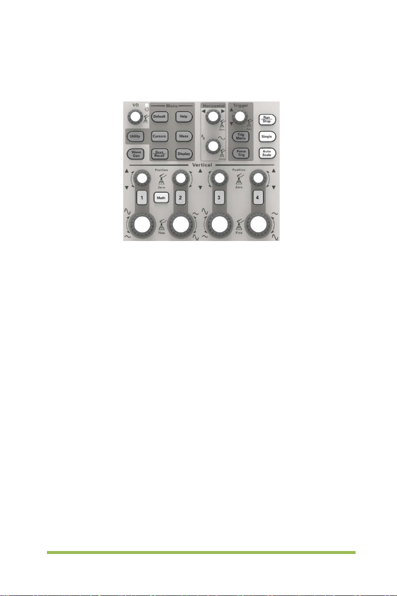
2.1 Menu and Control Keys
As shown in the figure below:
Figure 2-1 Control keys
All the keys are described as follows:
[CH1], [CH2] , [CH3], [CH4]: display setup menus of channel 1 and channel 2.
[Math]: display “Arithmetical operation” waveform menu.
[Horizontal]: Set Horizontal system.
[Trig Menu]: display Trigger control menu.
[Force Trig]: It is used for finishing acquisition of the current waveform no matter
whether the oscilloscope detects trigger, and it is mainly applied to “Normal” and
“Single” in the trigger mode.
[Default]: recall the default factory setup.
[Help]: enter the on-line help system.
[Utility]: display “UTILITY FUNCTION” menu.
[Cursors]: display the “CURSOR” menu. The [V0] knob can be used for
regulating the position of the cursor when the “CURSOR” menu is displayed and
the cursor is triggered.
[Meas]: show the “Measure” menu.
[Wave Gen]: show the waveform generator menu.
[Save Recall]: show the “Save/Recall” menu of setups and waveform.
[Display]: show the “Display” menu.
[Auto Scale]: automatically set the control state of the oscilloscope so as to
display suitable waveform.
Digital Storage Oscilloscope 10
Page 19
V0:
menu options (
Press this knob to reset data (trigger holdoff, overtime of the overtime
trigger and slope trigger), se
Press the
waveform generator function.
[Run/Stop]: continuously acquire waveform or stop acquisition
[Single]: Acquire a single trigger, finish acquisition and then stop.
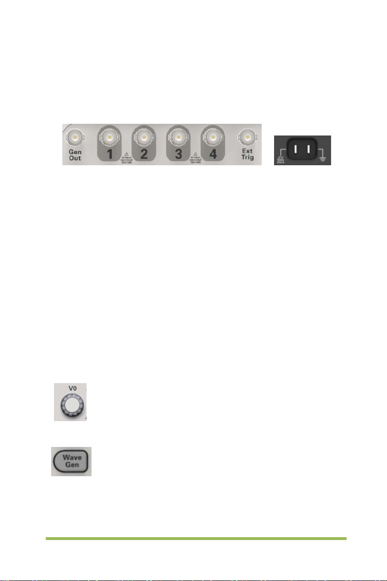
2.2 Connector
Figure 2-2 Connector
CH1, CH2, CH3, CH4: for an input connector of a measured signal.
EX T TRIG: be used as an input connector of an external trigger sourc e. Use
[Trig Menu] button to select “External” trigger source (only for Edge trigger), and
the trigger signal source can be used for triggering in the third channel while
acquiring data.
Gen Out: Waveform signal output.
Probe compensation: T he probe compensation signal is output and grounded
so that the probe is matched with the channels of the oscilloscope.
2.3 Universal Knobs and Softkeys
Universal Knob. Under different menu options, it supports selecting
MEASURE), moving cursors and levels (Slope Trigger).
lect menu options and so on. Easy to operate.
Wave Gen button on the front panel to open the arbitrary
Digital Storage Oscilloscope 11
Page 20
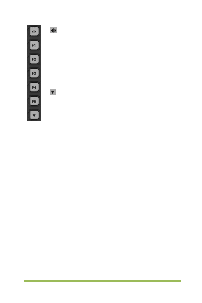
of the screen and give a full screen display of waveforms. Push it again to
show the menu options.
F1
functional. They are in charge of
selecting corresponding menu options on the screen in different menu
modes.
This functional softkey is mainly used to turn pages and confirm a
selection, such as
Hide/Show softkey. Push it to hide the menu options on the right side
-F5: These five softkeys are all multi-
‘next page’, ‘previous page’.
2.4 Oscilloscope Setup
While operating the oscilloscope, you may often use four features: Auto Scale, saving a
setup, recalling a setup and default setup. Hereinafter they are introduced one by one.
Auto Scale: This function can be used t o adjust the horizontal and vertical scales of
the oscilloscope automatically and set the trigger coupling, type, positi on, slope, level
and mode, etc., to acquire a stable waveform display.
Saving a Setup: By default, the oscilloscope will save the setup each time before
being closed, and automatic ally recall the setup once being turned on. (Note: If you
modify the setup, please wait for more than 10 seconds before turning off the
oscilloscope to ensure the proper s torage of new settings.) You can save 10 settings
permanently in the oscilloscope and reset them as necessary.
Recalli a Setup: The oscilloscope can recall any of your saved setups or the default
factory setup.
Default Setup: The oscilloscope is preset for normal operations when it is shipped
from the factory. This is the default setup. You may recall this setup at any time for your
requirements.
Digital Storage Oscilloscope 12
Page 21
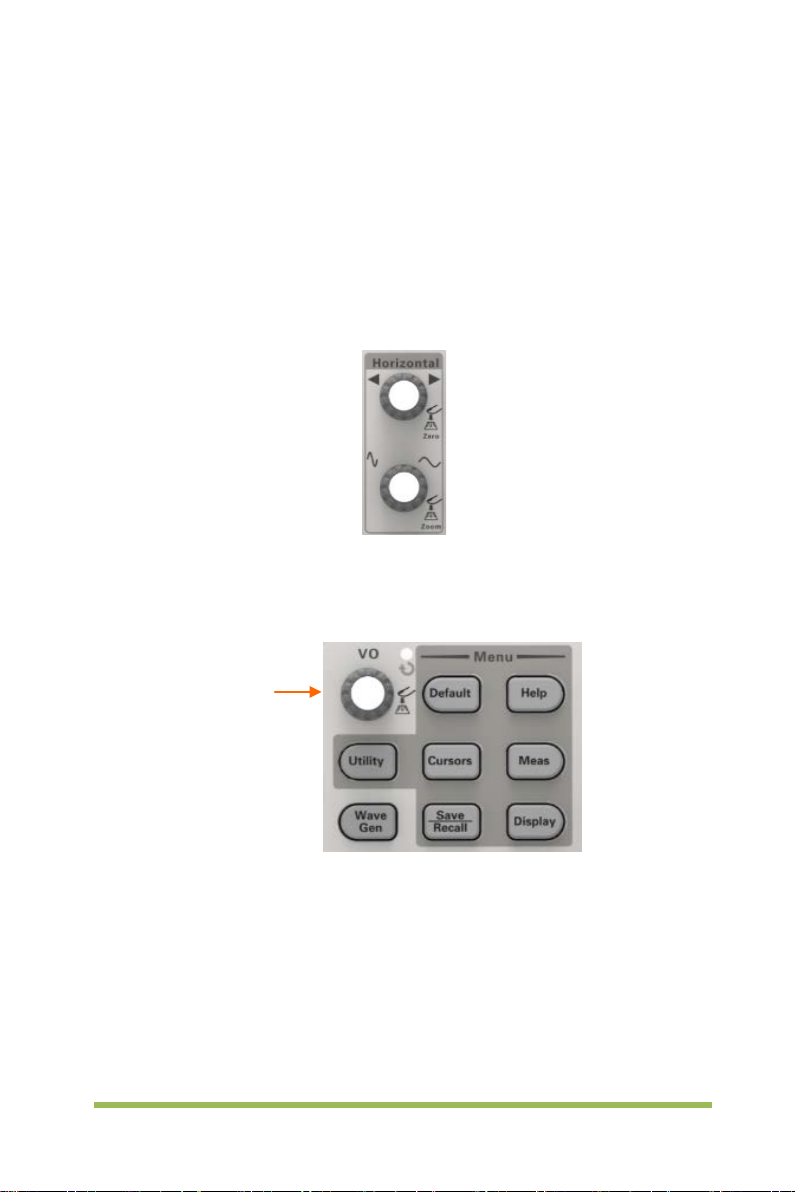
2.5 Horizontal Controls
Use the horizontal controls to change the horizontal scale and position of waveforms.
The horizontal position readout shows the time represented by the center of the screen,
using the trigger time as zero. When you change the horizontal scale, the waveform will
expand or contract to the screen center. The readout near the upper right of the screen
shows the current horizontal position in second. The oscill oscope also has an arrow
icon at the top of the graticule to indicate the horizontal pos iti on.
1. Horizontal Position Knob: Used to control t he trigger position against the screen
center. Push this button to reset the trigger point back to the screen center.
AN: Used to set the horizontal position as zero.
Universal Knob
2.SEC/DIV Knob: Used to change the horizontal time scale so as to magnify or
compress the waveform horizontally. If the waveform acquisition is stopped (by using
the [Run/Stop] or [Single] butt on), the SEC/DIV control will expand or compress the
waveform.
Note: Press SEC/DIV Knob to enter Dual-window Mode.
Digital Storage Oscilloscope 13
Page 22
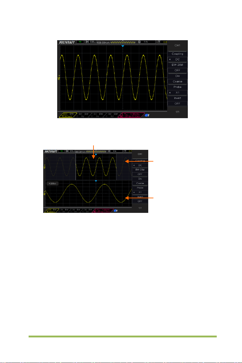
Location of expanded window data in memory
Minor Window
(Expanded Window)
Single-window Mode
Dual-window Mode (Full Screen)
Major Window
Press SEC/DIV Knob again to exit Dual-window Mode.
2.6 Vertical System
2.6.1 Vertical Controls
Vertical controls can be used to display and remove waveforms, adjust vertical scale
and position, set input parameters and perform math calculations. Each channel has a
separate vertical menu to set. See below for menu description.
Digital Storage Oscilloscope 14
Page 23

resolution to small steps between the Coarse
1X
Vertical Position
Volts/div
1. Vertical Position Knob: Move the channel waveform up and down on the screen.
In dual-window mode, move the waveforms in both windows at the same time in a
same direction. Push this knob to return waveforms to the vertical center position on
the screen. Two channels correspond to two knobs. Also you can press this knob to
switch between coarse and fine.
2. VOLTS/DIV Knob
Control the oscilloscope to magnify or attenuate the source signal of the channel
waveform. The vertical size of the display on the screen will change (increase or
decrease) to the ground level.
3. Menu (CH1, CH2, CH3, CH4): Display vert ical menu options; turn on or off the
display of channel waveforms.
Options Settings Comments
DC passes both DC and AC components of the input
Coupling
BW 20MHz
Div
DC
AC
GND
OFF
ON
Coarse
Fine
signal.
AC blocks the DC component of the input signal and
attenuates signals below 10Hz.
Ground disconnects the input signal.
Limits the bandwidth to reduce display noise; filters
the signal to eliminate noise and other unnecessary
HF components.
Selects the resolution of the VOLTS/DIV knob.
Coarse defines a 1-2-5 sequence. Fine changes the
settings.
Probe
10X
100X
1000X
Selects a value according to the probe attenuation
factor so as to ensure correct vertical readouts.
Reduce bandwidth to 6MHz when using a 1X probe.
Digital Storage Oscilloscope 15
Page 24

The invert function turns the displayed waveform 180
trigger is also inverted.
Invert
Coupling
If the channel adopts a DC coupling mode, you can quickly measure the DC
component of the signal by observing the difference between the waveform and the
signal ground.
If the channel adopts an AC coupling mode, the DC component in the signal is
filtered. By this mode, the AC component of the signal is displayed at a higher
sensitivity.
If the channel adopts a GND coupling mode, cut off the input signal. Inside the
channel, the channel input is connected with a zero volt reference electric level.
Fine Resolution
In the fine resolution setting, the vertical scale readout di splays the actual VOLTS/DIV
setting. The vertical scale changes only after you adjust the VOLT S/DIV control and set
to coarse.
Remove Waveform Display
To remove a waveform from the screen, first push the menu button to display the
vertical menu, then push again to remove the waveform. A channel waveform which is
unnecessary to be displayed can be used as a trigger source or for math operations.
OFF
ON
degrees, with respect to the ground level. When the
oscilloscope is triggered on the inverted signal, the
2.6.2 Math Operation
The series of scope supports many math operations between analog channels
waveforms, including addition (+), subtraction (-), multiplication (*), division (/) and FFT.
You can use cursors to measure it. The contents of this chapter:
• Units for Math Waveforms
• Math Operators
• To Adjust the Math Waveform Scale and Offset
Note: If the analog channel or the math function display is truncated (waveforms do not
display on the screen completely), the resulting math will also be truncated.
Digital Storage Oscilloscope 16
Page 25
Operation Unit
Addition (+)or subtraction (-) V
multiplication (*)
division (/) None
FFT dB, Vrms,
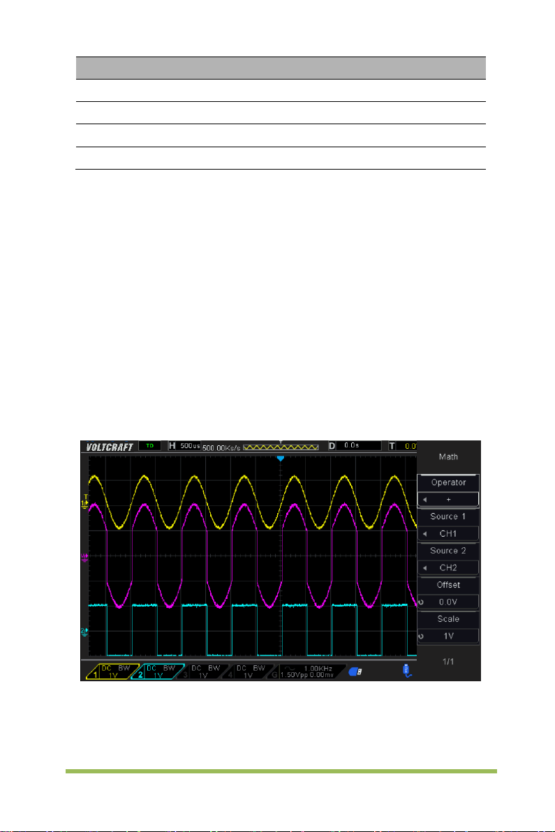
Addition or Subtraction
Math operators perform arithmetic operations - add or subtract operation - on any two
analog input channels. When you select addition or subtraction, the Source A and
Source B values are added or subtracted point by point, and the result is displayed.
1. Press the [Math] button on the front panel to enter the MATH function menu.
2. Press the Source 1 and Source 2 softkey respectively, and then turn the Universal
Knob to select the source to do math operation. Analog channels (CH1~CH4) can be
used as Source 1 or source 2.
3. Press the Operation softkey and then turn the universal to select + or -to make
addition or subtraction operation. The resulting math waveform is displayed on the
screen and labeled with “M”.
V∧2
Scale: Press the Scale s oftkey, and then turn the Universal Knob to select the vertical
scale.
Digital Storage Oscilloscope 17
Page 26

Multiplication and Division
Math operators perform arithmetic operations multiplication or divisi on operation on
any two analog input channels. When you select multiplication or division, the Source
1 and Source 2 values are multiplied or divided point by point and the result is
displayed.
1. Press the [Math] button on the front panel to enter the MATH function menu.
2. Press the Source 1and Source 2 softkey respectively, and then turn the Universal
Knob to select the source to do math operation. Analog channels (CH1 ~CH4) can be
used as Source 1 or source 2.
3. Press the Operation softkey and then turn the universal to select * or / to make
multiplication or division operation. The resulting math waveform is displayed on the
screen and labeled with “M”.
Scale: Press the Scale s oftkey, and then turn the Universal Knob to select the vertical
scale.
FFT Operation
FFT is used to compute the fast Fourier transform using analog input channels or
reference waveforms. FFT takes the digitized time record of the specified source and
transforms it to the frequency domain. When the FFT function is selected, the FFT
spectrum is plotted on the oscilloscope display as magnitude in dBV versus frequency.
The readout for the horizontal axis changes from time to frequency (Hertz) and the
vertical readout changes from volts to dB. FFT operation can facilitate the following
works:
Measure harmonic components and distortion in the system
Measure the characteristics of the noise in DC power
Analyze vibration
To display a FFT waveform:
1. Press the [Math] butt on on the front panel to open the MATH function menu.
2. Press the Operation softkey and then turn the Universal Knob to select FFT. The
resulting math waveform is displayed on the screen and labeled with “M”.
3. Press the Source soft k ey, and then turn the Universal Knob to select the source to
do FFT operation. Analog channels (CH1~CH4) can be used as the source.
Digital Storage Oscilloscope 18
Page 27

Window
Measurement
Characteristics
Waveform
same as no windows.
Waveform
Flattop
(Triangle)
stronger
Waveform
Better amplitude, poorer frequency accuracy
than Hanning
4. Press Center softkey and then turn the Universal Knob to adjust the frequency of
the frequency domain waveform corresponding to the horizontal center of the screen.
5. Press Span softkey and then turn the Universal Knob to adjust the the horizontal
scale of the frequency domain waveform.
6. Pres s the Vertical Units softkey to select the unit of vertical axis. The units of the
vertical axis can be dB or Vrms which use a logarithmic scale or a linear scale to
display vertical amplitude respectively. If you need to display the FFT frequency
spectrum in a relatively larger dynamic range, dBVrms is recommended.
7. Pres s the Scale softkey to select t he vert ical scal e.
8. Press the Window softkey, and then turn the Universal Knob to select an
appropriate window.
Spectral leakage can be considerably decreased when a window func tion is used. The
series of scope provides six kinds of FFT window functions which have different
characteristics and are applicable to measure different waveforms. You need to select
the window function according to different waveforms and their characteristics. Please
read the table below carefully to make an appropriate option according to the input
signal.
Pulse or
Rectangular
Hanning
Hamming
Blackman
Bartlett
Flattop
Transient
Periodic
Transient or
short pulse
Single frequency
signal, search for
higher order
harmonics.
Narrow band
signal with
Periodic
Special-purpose window applicable to
discontinuous waveforms. This is actually the
Better frequency, poorer a mplitude accuracy than
A litter bit better frequency resolution than
Hanning.
The best amplitude resolution; the poorest
frequency resolution
Better frequency resolution.
Digital Storage Oscilloscope 19
Page 28

9. Pres s the Show-Only softkey to select to display FFT operation results only and
not display the source channel.
Note:
Signals with DC components or deviation would cause an error or deviation of the
FFT waveform components. To reduce the DC components, set the C hannel Coupling
to AC.
To reduce the random noise and aliasing frequency components of repetitive or
single pulse, set the Acquisition of the oscilloscope to Average.
Using Cursors to measure FFT waveform
To make cursor measurements, press the Cursors button to turn the cursors, and then
press the Mode softkey to select Manual or Track, Use the AX and BX cursors to
measure frequency values and the difference between two frequency values (BX-AX).
Use the AY and BY cursors to measure amplitude in dB and difference in amplitude
(BY-AY).
2.7 Trigger System
The trigger determines when the oscilloscope begins to acquire data and display a
waveform. Once a trigger is properly set up, the oscilloscope can convert unstable
displays or blank screens to meaningful waveforms. Here introduce some basic
concepts about trigger.
Trigger Source: The trigger can be generated with multiple sources. The most
common one is the input channel (CH1~CH4). Whether the input signal is displ ayed or
not, it can trigger normal operations. Also the trigger source can be any signal
connected to an external trigger channel (only for Edge trigger).
Trigger Mode: You can select the Auto or Normal mode to define how the oscilloscope
acquires data when it does not detect a trigger condition. Auto Mode performs the
acquisition freely in absence of valid trigger. It allows the generation of untriggered
waveforms with the time base set to 100ms/div or slower. Normal Mode updates the
displayed waveforms only when the oscilloscope detects a valid trigger condition.
Digital Storage Oscilloscope 20
Page 29
Trigger Level
Indicates Trigger
Points
Acquisition Interval
Acquisition
Before this update, the oscilloscope still displays the old waveforms. This mode shall
be used when you want to only view the effectively triggered wveforms. In this mode,
the oscilloscope displays waveforms only after the first trigger. To perform a single
sequence acquisition, push the [Single] button.
Trigger Position: The horizontal position control establishes the time between the
trigger position and the screen center.
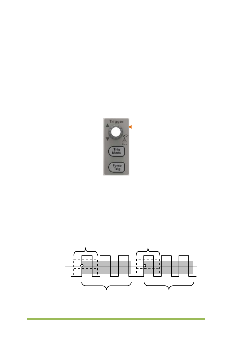
Trigger Level: It sets the amplitude level the signal must cross to cause an acquisition
when using the Edge or Pulse Width trigger.
Force Trigger: Used to complete an acquisition regardless of an adequate trigger
signal. This button becomes useless if the acquisition is already stopped.
Trigger Level
Holdoff: To use Trigger Holdoff, push the T rig Menu button and press Holdoff softkey.
The Trigger Holdoff function can be used to generate a stable display of complex
waveforms (such as pulse trains). Holdoff is the time between when the oscilloscope
detects one trigger and when it is ready to detect another. During the holdoff time, the
oscilloscope will not trigger. For a pulse train, the holdoff time can be adjusted to let the
oscilloscope trigger only on the first pulse in the train.
Holdoff
Interval
Holdoff
Digital Storage Oscilloscope 21
Page 30
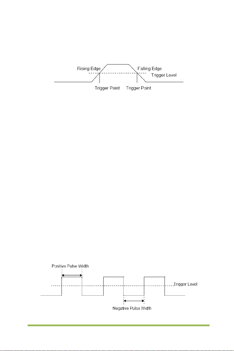
2.7.1 Edge Trigger
Edge trigger distinguishes the trigger points by seeking the specified edge (rising,
falling, rising & falling) and trigger level.
1. Press the [Trig Menu] button on the front panel to enter the Trigger system function
menu.
2. Press the Type softkey, turn the Universal Knob to set select “Edge” and then push
the knob to confirm.
3. Press the Source softkey, turn the Universal Knob to select CH1~CH4 or EXT as the
trigger source.
4. Press the Slope softkey, turn the Universal Knob to select the desired trigger edge
(rising, falling or rising & falling), and then press down the knob to confirm.
5. Turn the Trigger Level Knob to adjust the trigger level to obtain stable trigger.
6. Press o f 50% softkey to set the trigger level to the vertical midpoint bet ween the
peaks of the trigger signal.
The trigger level values are displayed at the upper right corner of the screen.
Note: Press the [Auto Scale] button will set the trigger type to Edge and slope to rising.
2.7.2 Pulse Trigger
Trigger on the positive or negative pulse with a specified width.
1. Press the [Trig Menu] button on the front panel to enter the TRIGGER function
Digital Storage Oscilloscope 22
Page 31

menu.
2. Press the Type softkey, turn the Universal Knob to select Pulse and then push the
knob to confirm.
3. Press the Source softkey, turn the Universal Knob to se lect CH1~CH4 as the
trigger source.
4. Turn the Trigger Level Knob to adjust the trigger level to the desired place.
5. Press the Polarity softkey to select Positive or Negative pulse that to trigger on.
6. Press the When softkey, turn the Universal Knob to select the desired condition,
and push down the knob to confirm.
< (less than a time value): trigger when the positive or negative slope time of
the input signal is lower than the specified time value.
For example, for a positive pulse, if you set t (pulse real width) < 100ns, the
waveform will trigger.
> (greater than a time value): tri gger when the positi ve or negative slope
time of the input signal is greater than the specified time value.
For example, for a positive pulse, if you set t (pulse real width) >100ns, the
waveform will trigger.
!= (not equal to time value): trigger when the positive or negative slope time
of the input signal is not equal to the specified time value.
= (equal to time value): tri gger when the positi ve or negative slope time of
the input signal is equal to the specified time value.
For example, for a positive pulse, if you set t (pulse real width) = 200ns, the
waveform will trigger.
Digital Storage Oscilloscope 23
Page 32

Triggers when pulse is equal to width
setting ±5%
Threshold level
Triggers when pulse is greater than
width setting
Tolerance
Tolerance
Triggers when pulse
than width setting
7. Press the Next Page softkey and press of 50% softk ey to set the trigger level to the
vertical midpoint between the peaks of the trigger signal.
The trigger level values are displayed at the upper right corner of the screen.
Trigger When: The pulse width of the source must be ≥5ns so t hat the oscilloscope
can detect the pulse.
is less
Triggers when pulse is not equal to
width setting ±5%
Threshold level
= Trigger Point
=, ≠: Within a ±5% tolerance, triggers the oscilloscope when the signal pulse
width is equal to or not equal to the specified pulse width.
<, >: Triggers the oscilloscope when the source signal pulse width is less than
or greater than the specified pulse width.
2.7.3 Video Trigger
Video triggering can be used to capture the complicated waveforms of most standard
analog video signals. The trigger circuitry detects the vertical and horizontal interval of
the waveform and produces triggers based on the video trigger settings you have
Digital Storage Oscilloscope 24
Page 33

selected. The series of scope support standard video signal fiel d or line of NTSC
(National Tel evision Standards Committee), PAL (Phase Alternating Line).
1. Press the [Trig Menu] button on the front panel to enter the Trigger function menu.
2. Press the Type softkey, then turn the Universal Knob to select Video and push
down the knob to confirm.
3. Press the Source softkey turn the Universal K nob to select CH1~CH4 as the trigger
source.
4. Press the Standard softkey to select the desired video standard. The series of
scope support the following video standards: PAL and NTSC.
5. Press the Sync softkey, then turn the Universal Knob to select field or line.
2.7.4 Slope Trigger
The slope trigger looks for a rising or falling transition from one l evel to anot her l evel i n
the specified time range. In the series of scope, positive slope time is defined as the
time difference between the two crossing points of trigger level line A and B with the
positive edge as shown in the figure below.
1. Press the [Trig Menu] button on the front panel to enter the Trigger function menu.
2. Press the Type softkey, turn the Universal Knob to set select Slop and then push
the knob to confirm.
3. Press the Source softkey, turn the Universal Knob to select CH1~CH4 as the trigger
source.
4. Press the Slop softkey, turn the Uni ver sal Knob to set select the desired trigger
edge (rising or falling), and then push down the knob to confirm.
5. Press the Level softkey and press of Lower Upper softkey to select Lower(V2) or
Upper(V1) the trigger level; then turn the Trigger Level Knob to adjust the position.
The trigger different level value between Upper and Lower is displayed at the upper
Digital Storage Oscilloscope 25
Page 34

right corner of the screen.
The Lower trigger level cannot be upper than the upper trigger level. V1 means the
upper trigger level while V2 means the lower trigger level.
6. Press the When softkey, then turn the Universal Knob to select the desired slope
condition, and push down the knob to confirm.
< (less than a time value): trigger when the positive or negative slope time of
the input signal is lower than the specified time value.
> (greater than a time value): tri gger when the positi ve or negative slope
time of the input signal is greater than the specified time value.
!=(not equal to a time value): trigger when the positive or negative slope time
of the input signal is not equal to the specif i ed time value..
=(equal to a time value): trigger when the positi ve or negative slope tim e of
the input signal is equal to the specified time value.
2.7.5 Overtime Trigger
Trigger when the time interval (△T) from when the rising edge (or falling edge) of the
input signal passes through the trigger level to when the neighboring falling edge (or
rising edge) passes through the trigger level is greater than the tim eout time set, as
shown in the figure below.
1. Press the [Trig Menu] button on the front panel to enter the Trigger system function
menu.
2. Press the Type softkey, then use the Universal Knob to select Overtime and push
down the knob to confirm.
3. Press the Source softkey, turn the Universal Knob to se lect CH1~CH4 as the
trigger source. Select channel with signal input as trigger source to obtain stable
trigger.
Digital Storage Oscilloscope 26
Page 35

4. Press the Polarity softkey to select Positive or Negative edge.
5. Pres s the Time softkey, turn the Universal Knob to select the desired value.
6. Press o f 50% softkey to set the trigger level to the vertical midpoint between the
peaks of the trigger signal.
2.7.6 Window Trigg er
Windows trigger provides a high trigger level and a low trigger level. The instrument
triggers when the input signal passes through the high tri gger level or the low trigger
level.
If the lower and the upper trigger levels are both within the waveform
amplitude range, the oscilloscope will trigger on both rising and falling edge.
If the upper trigger level is within the waveform amplitude range while the
lower trigger level is out of the waveform amplitude range, the oscilloscope
will trigger on rising edge only.
If the lower trigger level is within the waveform amplitude range while the
upper trigger level is out of the waveform amplitude range, the oscilloscope
will trigger on falling edge only.
1. Press the [Trig Menu] button on the front panel to enter the Trigger function menu.
2. Press the Type softkey, then use the Universal Knob to select Window and push
down the knob to confirm.
3. Press the Source softkey, turn the Universal Knob to select CH1~CH4 as the trigger
source.
4. Press Level softkey to select Lower or Upper trigger level or both level, then turn the
Trigger Level Knob to adjust the position. The trigger level values are displayed at the
upper right corner of the screen. The trigger different level value between Upper and
Digital Storage Oscilloscope 27
Page 36

Lower is displayed at the upper right corner of the screen.
The Lower trigger level cannot be upper than the upper trigger level. V1 means the
upper trigger level while V2 means the lower trigger level.
2.7.7 Pattern Trigger
Identify a trigger condition by looking for a specified pattern. This pattern is a logical
"AND" or “Or” combination of channels. Each channel can have a value of high (1), low
(0) or don't care (X). A rising, falling edge, rising or falling can be specifi ed for one
channel included in the pattern. When an edge is specified, the oscilloscope will trigger
at the edge specified if the pattern set for the other channels are true (namely the
actual pattern of the channel is the same with the preset pattern). If no edge is
specified, the oscilloscope will trigger on the last edge that makes the pattern true. If all
the channels in the pattern are set to "Don’t Care", the oscilloscope will not trigger.
To set interval trigger:
1. Press the [Trig Menu] button on the front panel to enter the Trigger system function
menu.
2. Press the Type softkey, then use the Universal Knob to select Pattern and push
down the knob to confirm.
3. Press the Logic softkey, turn the Universal Knob to select a logical "AND" or “Or”
combination of channels and push down the knob to confirm.
4. Press Pattern to set the pattern of the current signal source, turn the Universal
Knob to select a pattern. At this point, the corresponding pattern is displayed on the
Digital Storage Oscilloscope 28
Page 37

menu. The patterns of channels CH1-CH4 are presented from left to right. You can set
the pattern of a signal source when the souce is open. Press Pattern softkey to se t
pattern for other source.
1: Set the pattern of the channel selected to "H", namely the voltage level is higher
than the trigger level of the channel.
0: Set the pattern of the channel selected to "L", namely the voltage level is lower
than the trigger level of the channel.
X: Set the pattern of the channel selected to "Don’t Care", namely this channel is
not used as a part of the pattern. When all channels in the pattern are set to "Don’t
Care", the oscilloscope will not trigger.
: Set the pattern to the rising edge of the channel selected.
: Set the pattern to the falling edge of the channel selected.
: Set the pattern to the rising or falling edge of the channel selected.
5. Pres s the Level softkey to set the trigger level. For the analog channels, the trigger
level of each channel needs to be set independently. For example, set the trigger level
of CH1. Press Level softkey to select CH1, and then use Trigger level knob to modify
the level. Press Pattern softkey to set the trigger level for other source.
2.7.8 Interval Trigger
Trigger when the time difference between the neighboring rising or falling edges meets
the time limit c ondi tion (<, >, !=, =).
To set interval trigger:
1. Press the [Trig Menu] button on the front panel to enter the Trigger system function
Digital Storage Oscilloscope 29
Page 38

menu.
2. Press the Type softkey, then use the Universal Knob to select Interval and push
down the knob to confirm.
3. Press the Source softkey, turn the Universal Knob to select CH1~CH4 as the trigger
source.
4. Press the Slope softkey to select rising or falling edge.
5. Press the When softkey, turn the Universal Knob to select desired condition.
< (less than a time value): trigger when the positive or negative pulse time of
the input signal is less than the specified time value.
> (greater than a time value): tri gger when the positi ve or negative pulse
time of the input signal is greater than the specified time value.
!= (not equal to a time value): trigger when the positive or negative pulse
time of the input signal is not equal to the specified limit of time.
= (equal to a time value): trigger when the positi ve or negative pulse tim e of
the input signal is equal to the specified limit of time.
6. Press the When s of tkey (<, >, !=, =), turn the Universal Knob to select the desired
condition.
2.7.9 Under Amp Trigger
The Runt trigger looks for pulses that cross one threshold but not another as shown in
the picture below.
A positive runt pulse across through a lower threshold but not an upper threshold.
A negative runt pulse across through an upper threshold but not a lower threshold.
Digital Storage Oscilloscope 30
Page 39

To trigger on runt pulse:
1. Press the [Trig Menu] button on the front panel to enter the Trigger system function
menu.
2. Press the Type softkey, then turn the Universal Knob to select Under Amp and
push down the knob to confirm.
3. Press the Source softkey, turn the Universal Knob to se lect CH1~CH4as the
trigger source.
4. Press the Polarity softkey to select Positive or Negative pulse to trigger.
5. Press the When softkey, turn the Universal Knob to select the desired condition
(<, >, != or =).
6. Press the Width softkey, and then turn the Universal Knob to select the desired
value.
7. Press the Next Page softkey to enter the second page of the TRIGGER system
function menu. Press the Level softkey to select Lower or Upper trigger level, and the
turn the Universal Knob to set the position.
2.7.10 UART Trigger
To trigger on UART trigger:
1. Press the [Trig Menu] button on the front panel to enter the Trigger system function
menu.
2. Press the Type softkey, then turn the Universal Knob to select UART and push
down the knob to confirm.
3. Press the Source softkey, turn the Universal Knob to se lect CH1~CH4 as the
trigger source.
4. Set the following parameters.
Idle Level - Set the idle level High or Low to match your device under test.
Baud - Press the Baud Rate softkey, then press the Universal Knob and select a
baud rate to match the signal in your device under test. If the desired baud rate is not
listed, select Custom on the Baud softkey, and then press the Custom softkey and turn
the Universal Knob to set the desired baud rate.
Parity - Parity Check. Choose odd, even, or none, based on your device under test.
Digital Storage Oscilloscope 31
Page 40

Data Bits - Data Length, Set the number of bits in the UART2 words to match your
device under test (selectable from 5-8 bits).
5. Press the When softkey and set up the desired trigger condition:
Start - The oscilloscope triggers when a start bit occurs.
Stop - Triggers when a stop bit occurs on measured signal. The trigger occurs on
the first stop bit regardless of using 1, 1.5 or 2 stop bit.
Spec Data - Triggers on a data byte that you specify. For use when the devi ce under
test data words are from 5 to 8 bits in length
a. Press the When softkey, and choose an equality qualifier. You can choose
equal to(=), not equal to(!=), less than(<), or great er than(>) a specific data value.
b. Press the Data softkey, and turn V0 to set the data value for your trigger
comparison. The range of the data value is 0x00 to 0xff.
This works in conjunction with the When softkey.
Parity error: The oscilloscope triggers when t he parity check is error when there is
parity check.
Com error: The oscilloscope triggers when the received data is error.
Note: Use V0 to set the data. When the arrow shows vertical on the top left of Data
menu, turn V0 to set the value of the current data bit; then press V0, the arrow s hows
horizontal, and turn V0 to select the data bits that you want to set.
: Horizontal arrow, turn the Universal Knob to select a digit.
: arrow, turn the Universal Knob to set the value of the selected digit.
For example1, source: CH1; baud: 19200; Idle: High; Parity: No; Data Bit: 8; when:
“Start”. The trigger result is shown below:
Digital Storage Oscilloscope 32
Page 41

For example2, source: CH1; baud: 19200; Idle: High; Parity: No; Data Bit: 8; when:
“Stop”. The trigger result is shown below:
For example3, source: CH1; baud: 19200; Idle: High; Parity: No; Data Bit: 8; Data:
0x55; When: Spec Data; When: equal (=).The trigger result is shown below:
Digital Storage Oscilloscope 33
Page 42

Uart Decode interpretation:
1. The decode data is displayed in hexadecimal;
2. The decoded data is at the bottom of the waveform interface. The color of decode
data is displayed purple;
3. When there are " ?" or "adjust the time base", you need to adjust the time base to
see the decoding results.
UART text interface is shown as below:
Digital Storage Oscilloscope 34
Page 43

1. Run/Stop decode;
2. Return to the previous interface;
3. Save data. Available when the USB memory device is inserted.
4. Decoded data area.
2.7.11 LIN Trigger
LIN triggering can trigger on the rising edge at the Sync Break exit of the LIN
single-wire bus signal (that marks the beginning of the message frame), the Frame ID,
or the Frame ID and Data. A LIN signal message frame is shown below:
1. Press the [Trig Menu] button on the front panel to enter the Trigger system function
menu.
2. Press the Type softkey, then turn the Universal Knob to select LIN and push down
the knob to confirm.
3. Press the Source softkey, turn the Universal Knob to se lect CH1~CH4 as the
trigger source.
4. Press the Buad Tate softkey, and turn the Universal Knob to set the Baud Rate.
5. Press the Idle Level softkey, and turn the Universal Knob to set the Idle Level.
6. Press the Identifier softkey, and turn the Universal Knob to set the Identifier. The
range is from 0x00 to 0x3f.
7. Press When softkey to set trigger condition.
• Interval Field - The oscilloscope triggers when the interval field end.
Digital Storage Oscilloscope 35
Page 44

• Sync Field –The oscilloscope triggers when the synchronous field end.
• Id Field –The oscilloscope triggers when the Id field end.
• Sync Id Error - The oscilloscope triggers when the Synchronizat i on ID ERROR
end.
• Identifier (Frame ID) - The oscilloscope triggers when a frame with an ID equal to
the selected value is detected. Use the Universal Knob to select the value for the
Frame ID.
• ID and Data (Frame ID and Data) - The oscilloscope triggers when a frame with
an ID and data equal to the selected values is detected. Use the Universal Knob
to select the value for the ID and Data.
--Press Data software, use V0 to set the data, refer to
--Data Mask: When set to "ON", the data is ignored when it is triggered; the
setting is "OFF", and the data on the data line must be consistent with the data
of the index so that it can trigger;
--Data Index: The range is 0 to 3. It can set four hexadecimal data.
For example, source: CH1; baud: 19200; Idl e: High; When: ID and Data; ID: 0x25;
Data: 00 01 02 03. And set the trigger level. The trigger result is shown below:
2.7.10;
Digital Storage Oscilloscope 36
Page 45

LIN Decode interpretation:
1. The decode data is displayed in hexadecimal;
2.
T he decoded dat a is at the bottom of the waveform interface. The c olor of “frame
ID” and “checksum”decode data is displayed purple;
3. When there are "?" or "adjust the time base", you need to adjust the time b as e to
see the decoding results.
4.
In the Lin decode result, the synchronous field "55" is not decoded and displayed.
LIN text interface is shown as below:
1. ID: The ID value of the current frame;
2. Data: The data of the current frame;
3. Checksum.
2.7.12 CAN Trigger
1. Press the [Trig Menu] button on the front panel to enter the Trigger system function
menu.
2. Press the Type softkey, then turn the Universal Knob to select CAN and push down
the knob to confirm.
3. Press the Source softkey, turn the Universal Knob to se lect CH1~CH4 as the
trigger source.
Digital Storage Oscilloscope 37
Page 46

4. Press the Buad Tate softkey, and turn the Universal Knob to set the Baud Rate.
5. Press the Idle Level softkey, and turn the Universal Knob to set the Idle Level.
6. Press the Identifier softkey, and turn the Universal Knob to set the Identifier.
Note: The Identifier means Remote ID and Data ID.
7. Press When softkey to set trigger condition.
• Start - The oscilloscope triggers at the start of a frame.
• Remote ID- The oscilloscope triggers on remote frames with the specified ID.
• Data ID - The oscilloscope will trigger on data frames matching the specified ID
• Frame ID - The oscilloscope will trigger on data frames od remote frames
matching the specified frame data.
• Data Frame and data –The oscilloscope will trigger on data frames matching the
specified data frame ID and data.
a. Press the Data softkey to select the ID number.
b. Press the Data softkey to move the current bit, and turn the universal to select
the byte to be set.
--Press Data software, use V0 to set the data, refer to
--Data Mask: When set to "ON", the data is ignored when it is triggered; the
setting is "OFF", and the data on the data line must be consistent with the data
of the index so that it can trigger;
--Data Index: The range is 0 to 3. It can set four hexadecimal data.
• Error –The oscilloscope will trigger on error frames matching the specified data.
• All Error - The oscilloscope will trigger when any form error or active error is
encountered. Not include judgment of CRC errors.
• Ack Error –The oscilloscope will trigger when the comfirm is high.
• Overload Frame - The oscilloscope will trigger on overload frames.
For example1, Source: CH1; Baund Rate: 1000000; Idle Level: Low; When: Start Bit.
The trigger result is shown below:
2.7.10;
Digital Storage Oscilloscope 38
Page 47

For example2, Source: CH1; Baund Rate: 1000000; Idle Level: Low; When: Data ID;
Identifier: 0x12efabcd. The trigger result is shown below:
CAN Decode interpretation:
1. The decode data is displayed in hexadecimal;
2.
T he decoded dat a is at the bottom of the waveform interface. The c olor of “frame
ID” is displayed purple, the “Data” is orange, t he “CRC” is purpl e;
3. When there are " ?" or "adj ust the time base", you need to adjust the time base to
see the decoding results.
Digital Storage Oscilloscope 39
Page 48

CAN text interface is shown as below:
1. ID: The ID value of the current frame, displayed as hexadecimal;
2. Frame type: “SFF”- Standard data frame, “SRF”- Standard remote frame, “EFF”Extended data frame, “ERF”- Extended remote frame;
3. DLE: Data bytes of current frame;
4. Data: The data of current frame;
5. CRC:The CRC check code of current frame.
2.7.13 SPI Trigger
In SPI trigger, when timeout condition is satisfied, the oscilloscope triggers when the
specified data is found. When using SPI trigger, you need to specify the SCL clock
sources and SDA data sources. Below is the sequential chart of SPI bus.
1. Press the [Trig Menu] button on the front panel to enter the Trigger system function
menu.
2. Press the Type softkey, then turn the Universal Knob to select SPI and push down
the knob to confirm.
Digital Storage Oscilloscope 40
Page 49

3. Source Selection: Press SCL and SDA softkey to specify the data sources of SCL
and SDA respectively. They can be set to CH1-CH4.
Note: Select channel with signal input as trigger source to obtain stable trigger.
4. Data Line Setting:
Press Data Width to set the number of bits of the serial data character string. The
serial data string can be specified to be from 4, 8, 16, 24, 32 bits long.
Press Da ta softkey, use V0 to set the data, refer to
Data Mask: it is hexadecimal, 0-Mask, f-No Mask, 1~e mask some data.
5. Trigger Condition: Press Overtime softkey to set the timeout, the range is from 8 ns
to 10 s.
Timeout: the clock (SCL) signal need to maintain a certain idle time before the
oscilloscope searches for a trigger. The oscilloscope will trigger on when the data (SDA)
satisfying the trigger conditions is found.
6. Slope: Clock Edge: Press Slope softkey to sel ect the desired clock edge.
Rising: sample the SDA data on the rising edge of the clock.
Falling: sample the SDA data on the falling edge of the clock.
7. When select SCL channel, press SCL and use Trigger Level knob to modify the
trigger level of the SCL channel. When select SDA channel, use Trig g er L evel knob to
modify the trigger level of the SDA channel.
For example: SCL: CH1; SDA: CH2; Slope: Rising; Data Width: 8; Data Mask:
0x000000ff; Data: 0x000000f5; Overtime: 190ns. The trigger result is shown below:
2.7.10.
Digital Storage Oscilloscope 41
Page 50

SPI Decode interpretation:
1. The decode data is displayed in hexadecimal;
2.
The decoded data is at the bottom of the waveform interface. The color of “Data”
is displayed purple;
3. When there are "?" or "adjust the time base", you need to adjust the time base to
see the decoding results.
SPI text interface is shown as below:
1. Run/Stop decode;
Digital Storage Oscilloscope 42
Page 51

2. Return to the previous interface;
3. Save data. Available when the USB memory device is inserted.
4. Decoded data area.
2.7.14 IIC Trigger
IIC (Inter-IC bus) signals setup consists of connecting the oscilloscope to the serial
data (SDA) line and the serial clock (SCL) line and then specifying the input signal
threshold voltage levels.
To set up the oscilloscope to capture IIC signals, please refer to the following:
1. Press the [Trig Menu] button on the front panel to enter the Trigger system function
menu.
2. Press the Type softkey, then turn the Universal Knob to select IIC and push down
the knob to confirm.
3. Source Selection: Press SCL and SDA softkey, turn the Universal Knob to to specify
the data sources of SCL and SDA respectively. They can be set to CH1-CH4.
4. Press When softkey to set trigger condition. Select trigger condition “Start Bit”,
connect the SCL signal to CH1 and connect the SDA signal to CH2.
Press the corresponding Level softkey; then, t urn the Trigger Level knob to set the
signal threshold voltage level.
• Data must be stable during the entire high clock cycle or it will be interpreted
as a start or stop condition (data transitioning while the clock is high).
Digital Storage Oscilloscope 43
Page 52

Trigger condition:
Trigger Condition: Press When softkey to select the desired trigger condition.
• Start: trigger when SDA data transitions from high level to low level while SCL is
high level.
• Stop: trigger when SDA data transitions from low level to high level while SCL is
high level.
• MissedACK: trigger when the SDA data is high level during any acknowledgement
of SCL clock position.
• Address: the trigger searches for the specified address value. When this event
occurs, the oscilloscope will trigger on the read/write bit.
The AddrBits is "7 bits"; --so the range can be from 0 to 0x7F.
• Restart: trigger when another start condition occurs before a stop condition.
• Address and Data: the trigger searches for the specified address and data value on
the data line (SDA). When this event occurs, the oscilloscope will trigger on the
clock line (SCL) transition edge of the last bit of data. After this trigger condition is
selected:
Digital Storage Oscilloscope 44
Page 53

--Press Data software, use V0 to set the data, refer to 2.7.10;
--Data Mask: When set to "ON", the data is ignored when it is triggered; the
setting is "OFF", and the data on the data line must be consistent with the data
of the index so that it can trigger;
--Data Index: The range is 0 to 3. It can set four hexadecimal data.
Trigger Level:
5. When select SCL channel, press SCL and use Trigger Level knob to modify the
trigger level of the SCL channel. When select SDA channel, use Trig g er L evel knob to
modify the trigger level of the SDA channel.
For example1: SCL: CH1; SDA: CH2; When: Start Bit. T he trigger result is shown
below:
For example2: SCL: CH1; SDA: CH2; When: Address and Data; Address: 09; Data: 3f
xx xx xx (The data mask of index 0 is “OFF”, the data mask of others are “ON”). The
trigger result is shown below:
Digital Storage Oscilloscope 45
Page 54

IIC Decode interpretation:
1. The decode data is displayed in hexadecimal;
2.
The decoded data is at the bottom of the waveform interface. The color of
“Address” and “Data” are displayed purple;
indicates the read operation, "D" indicates the decoded data, "~A" indicates the
unacknowledged bit;
3. When there are "?" or "adjust the time base", you need to adjust the time base to
see the decoding results.
IIC text interface is shown as below:
"W" indicates the write operation, "R"
Digital Storage Oscilloscope 46
Page 55

1. Address: In the address bar, "R" represents the read operation, and "W"
represents the write operation;
2. Data: It is the data sent by a read or write operation;
3. ADDR ACK: "Y" means response, and "N" means no response.
2.8 Save/Recall
Oscilloscope setups, waveforms, Ref, and CSV files can be saved to internal
oscilloscope memory or to a USB storage device. The saved setups, waveforms and
Ref can be recalled from an USB Host interface on the front panel to connect an USB
device for external storage.
The scope supports setups, waveforms, Ref and CSV files storage. The default save
type is setups.
1. Setups
It‘s the default storage type of the scope. It saves the settings of the oscilloscope in
internal or external memory in “.SET” format. At most 9 setting files (from No.1~No.9)
can be stored in internal memory. The stored settings can be recalled.
2. Wave(Binary)
The scope saves the waveform data in memory in “.lwf format.
3. Reference
The scope saves the waveform data in memory in “.REF” format. At recall, the
reference waveform will be displayed on the screen directly.
4. CSV
It saves the waveform data in external memory in “.CSV” format. The stored files
contain the waveform data of the displayed analog channels and the main setting
information of the oscilloscope. The recall of CSV file is not supported.
2.8.1 Internal Save and Recall
Internal save and recall support Setups in Save/Recall. In the following part, the save
and recall method and procedures are introduced.
Digital Storage Oscilloscope 47
Page 56

Save the specified oscilloscope setting in internal memory.
1. Connect the signal to the oscilloscope and obtain stable display.
2. Press [Save/Recall] button on the front panel to enter the SAVE/RECALL function
menu.
3. Press the Save softkey and t hen turn t he Universal Knob to select Setup and then
press the knob to confirm.
4. Press the Save To softkey to select Internal to save the current setup of the
oscilloscope to the internal memory.
5. Press the SetUp softkey button, then turn the Universal Knob to select the location
to save. The internal memory can save as many as 9 setup files, from No.1~No.9.
6. Press the Save softkey to save the current setup to the appointed location. After a
few seconds, it will pop-out the message “Save successfully”.
Load the specified type of file in internal memory.
If want to recall the setup after having finished the steps above, please do the following
steps: Press the Recall softkey, and then turn the Universal Knob to select the
location that you want to recall, press the Recall softkey to recall the setup, and it will
pop-out the message “Recall Successfully”.
Note: if need to delete a setup file in the memory, please save a new setup to the same
location to overwrite it.
2.8.2 External save and recall
Before using external storage and recall, make sure that the USB flash device is
connected correctly. External storage supports all the types of files in save, but in recall,
CSV are not supported.
Save the specified type of file in the external USB flash device.
1. Press the [Save/Recall] button on the front panel to enter the SAVE/RECALL
function menu.
2. Insert the USB storage device into the front panel USB Host interface, if thedevice is
Digital Storage Oscilloscope 48
Page 57

recognized successful, the pop-uptip “Storage device is connected”.
3. Press the Save softkey to select Save Type.
4. Use the SaveTo softkey to external location. Press Save softkey and into USB
storage interface. File can be stored under the root directory or in a certain folder under
the root directory of the USB storage device.
5. Press the Save softkey t o save the current waveform to the external USB storage
device,
Load the specified type of file in the external USB storage device.
1. Insert the USB storage device into the front panel USB Host interface, if thedevice is
recognized successful, the pop-uptip “Storage device is connected”.
2. Press the [Save/Recall] button on the front panel to enter the SAVE/RECALL
function menu.
3. Press the Type softkey to select Wave or Setup
4. Pres s the Recall softkey to enter the SAVE/RECALL file system.
5. Turn the Universal Knob to select the file to be recalled, press the Recall softkey to
recall the waveform or setup.
2.9 Measure System
The oscilloscope displays graphs of voltage versus time and can help to measure the
displayed waveform. There are several ways to take measurements, using the
graticule, the cursors or performing an automatic measurement.
2.9.1
Graticule: This method allows you to mak e a quick, visual estim ate and t ake a sim ple
measurement through the graticule divisions and the scale factor.
For example, you can take simple measurements by counting the m ajor and minor
graticule divisions involved and multiplying by the scale factor. If you counted 6 major
vertical graticule divisions between the minimum and maximum values of a waveform
and knew you had a scale factor of 50mV/division, you could easily calculate your
peak-to-peak voltage as follows:
6 divisions x 50mV/division = 300mV.
Scale measurement
Digital Storage Oscilloscope 49
Page 58

Options
Settings
Comments
Track
MATH
Use the readouts to show the measurement.
AYBY
location of the cursor.
2.9.2 Cursor measurement
Cursor: This method allows you to take measurements by moving the cursors.
Cursors always appear in pairs and the displayed readouts are just their measured
values. There are two kinds of cursors: Amplitude Cursor and Time Cursor. The
amplitude cursor appears as a horizontal broken line, measuring the vertical
parameters. The time cursor appears as a vertical broken line, measuring the
horizontal parameters.
The cursor measurement include s two modes: Manual mode and Tracking mode.
1. Manual mode:
Horizontal cursors or vertical cursors appear in pair to measure time or voltage, and the
distance between the cursors can be manually regulated. The signal source should be
set as a waveform to be measured before the cursors are used.
2. Tracking mode:
A horizontal cursor is intersected with a vertical cursor to form a cross cursor. The cross
cursor is automatically located on the waveform, and the horizontal position of the
cross cursor on the waveform is regulated by selecting “Cur A” or “Cur B” and rotating
the [UNIVERSAL] knob. The coordinates of the cursor point will be displayed on the
screen of the oscilloscope.
Push the CURSOR button to display the Cursor Menu.
Mode
Source
Select
Cursor
Moving Cursors: Press the key near Select Cursor to select a cursor and turn
Universal Knob t o move it. Cursors can be moved only when the Cursor Menu is
displayed.
Manual
CH1~CH4
AX(BX)
AXBX
AY(BY)
Select a measurement cursor and display it.
Select a waveform to take the cursor measurement.
A selected cursor is highlighted, which can be moved
freely. Both cursors can be selected and moved at the
same time. The box behind the cursor displays the
Digital Storage Oscilloscope 50
Page 59

2.9.3 Automatic Measurement
Automatic Measurement: The oscilloscope performs all the calculations automatically
in this mode. As this measurement uses the waveform record points, it is m ore precise
than the graticule and cursor measurements. Automatic measurements show the
measurement results by readouts which are periodically updated with the new data
acquired by the oscilloscope.
Push the Meas button to perform auto measurements. There are 32 types of
measurements and up to 4 can be displayed at a time.
Perform the steps below and select voltage or time parameters to make automatic
measurements.
1. Press the [Meas] button on the front panel to enter the Measure function menu.
2. Press the Source softkey, and then use the Universal Knob to select the desired
channel.
3. Press the Type softkey, and then turn the Universal Knob to select the desired
measurement parameter.
4. Press the Univer sal Knob to add the measurement parameter, the parameters and
value will be shown above the menu, and the statistics status will update.
5. To turn off the statistic function, press the Statistics softkey to select OFF.
Digital Storage Oscilloscope 51
Page 60

The measurement display area can display 4 measurement parameters at most, and
the measurements will arrange according to the selecting order. If add a sixth
measurement parameter, it will delete the first measurement.
Note: If the parameter does not match the measured condition, it will display as “*****”.
To Clear Measurement Parameters
Press the Clear All softkey to clear all the measurement parameters that are displaying
on the screen.
Statistic Function
Make statistic and display the current, average, minimum, maximum, root mean square
error and count values of at most 4 measurement items that are turned on last.
1. Press the [Meas] button on the front panel to enter the Measure function menu.
2. Press the Statistics softkey to select ON.
To Make All Measurement
All measurement could measure all parameters of the current measurement source
and display the results on the screen.
Do the following steps to make all parameters measurement.
1. Press the [Meas] button on the front panel to enter the MEASURE function menu.
2. Press the All Measure softkey to se l ec t ON.
3. Press the Source softkey to select the measure source (CH1~CH4).
Digital Storage Oscilloscope 52
Page 61

the first cycle.
entire waveform.
Calculate the absolute difference between the
peaks of the entire
waveform.
entire waveform.
complete cycle in the waveform.
the entire waveform.
entire waveform.
first rising edge of the waveform.
first falling edge of the waveform.
Options
Source
Measurement Type
1 Frequency
2 Period Calculate the time of the first cycle.
3 Average
4 Pk-Pk
5 RMS
6 PeriodRms
7 Min
8 Max
9 RiseTime
10 FallTime
Settings Comments
CH1~CH4
Select the measure source.
Calculate the waveform frequency by measuring
Calculate the arithmetic mean voltage over the
greatest and the smallest
Calculate the Root Mean Square voltage over the
Calculate the actual RMS measurement of the first
The most negative peak voltage measured over
The most positive peak voltage measured over the
Measure the time between 10% and 90% of the
Measure the time between 90% and 10% of the
Digital Storage Oscilloscope 53
Page 62

level.
and the next rising edge at the waveform 50%
level.
period.
period.
voltage over the entire
waveform.
Measure the lowest voltage over the entire
waveform.
top.
18
Vamp
Voltage between Vtop and Vbase of a waveform.
over the entire waveform.
over the entire waveform.
first cycle in the waveform.
falling.
Vlow)/Vamp before the
waveform falling.
waveform.
and the first falling edge of source 2.
11 + Width
12 - Width
13 + Duty
14 - Duty
Measure the time between the first rising edge
and the next falling edge at the waveform 50%
Measure the time between the first falling edge
Measure the first cycle waveform. Positive Duty
Cycle is the ratio between positive pulse width and
Measure the first c ycle waveform. Negative Duty
Cycle is the ratio between positive pulse width and
15 Vbase
16 Vtop
17 Vmid
19 Overshoot
20 Preshoot
21 PeriodAvg
22 FOVShoot
23 RPREShoot
24 BWidth
25 FRR
26 FFF
27 FRF
Measure the highest
Measure the voltage of the 50% level from base to
Defined as (Base - Min)/Amp x 100 %, Measured
Defined as (Max - Top)/Amp x 100 %, Measured
Calculate the arithmetic mean voltage over the
Defined as (Vmin-Vlow)/Vamp after the waveform
Defined as (Vmin-
The duration of a burst measured over the entire
The time between the first rising edge of source 1
and the first rising edge of source 2 of 50 voltage
level.
The time between the first falling edge of source 1
and the first falling edge of source 2 of 50 voltage
level.
The time between the first rising edge of source 1
Digital Storage Oscilloscope 54
Page 63

and the first rising edge of source 2.
and the last rising edge of source 2.
and the last falling edge of source 2.
and the last rising edge of source 2.
and the last falling edge of source 2.
28 FFR
The time between the first falling edge of source 1
29 LRR
30 LRF
31 LFR
32 LFF
Off Do not take any measurement.
The time between the first rising edge of source 1
The time between the first rising edge of source 1
The time between the first falling edge of source 1
The time between the first falling edge of source 1
2.10 Acquire
Run Control
Press the [Run/Stop] or [Single] button on the front panel to run or stop the sampling
system of the scope.
When the [Run/Stop] is green, the oscilloscope is running, that is, acquiring data when
trigger conditions are met. To stop acquiring data, press the [Run/Stop] button. When
stopped, the last acquired waveform is displayed.
When the [Run/Stop] button is red, data acquisition is stopped. Red "Stop" is
displayed next to the trademark logo in the status line at the top of the display. To start
acquiring data, press [Run/Stop].
To capture and display a single acquisition (whether the oscilloscope is running or
stopped), press [Single] button. The Single run control lets you view single-shot events
without subsequent waveform data overwriting the display.
When [Single] is pressed the display is cleared, the trigger mode is temporaril y set to
Normal (to keep the oscilloscope from auto-triggering immediatel y), the trigger c i rcui t ry
is armed, the Single key is illuminated, and the oscilloscope waits until a user defined
trigger condition occurs before it displays a waveform.
When the oscilloscope triggers, the single acquisition is displayed and the oscilloscope
is stopped (the [Run/Stop] button is illuminated in red). Press [Single] button again to
acquire another waveform.
When you acquire an analog signal, the oscilloscope will convert it into a digi tal one.
Digital Storage Oscilloscope 55
Page 64

Options
Settings
Comments
The real-time acquisition has four modes: Normal, Peak Detect, Average and High
Resolution. The acquisition rate is affected by the setting of time base.
Normal: In this acquisition mode, the oscilloscope samples the signal in evenly spaced
intervals to establish the waveform. This mode accurately represents signals in most
time. However, it does not acquire rapid variations in the analog signal that may occur
between two samples, whi c h c an result in aliasing and may cause narrow pulses to be
missed. In such cases, you should use the Peak Detect mode to acquire data.
Peak Detect: In this acquisition mode, the oscilloscope gets the maximum and
minimum values of the input signal over each sample interval and uses these values to
display the waveform. In this way, the oscilloscope can acquire and display those
narrow pulses that may have otherwise been missed in Normal mode. However, noise
will appear to be higher in this mode.
Average: In this acquisition mode, the oscilloscope acquires several waveforms,
averages them, and displays the resulting waveform. You can use t hi s m od e t o r ed u ce
random noise.
High Resolution(HR): This mode uses a kind of ultra-sample technique to average the
neighboring points of the sample waveform to reduce the random noise on the input
signal and generate much smoother waveforms on the screen. This is generally used
when the sample rate of the digital converter is higher than the storage rate of the
acquisition memory.
Note: "Average" and "HR" modes use different averaging methods. The former uses
"Multi-sample Average" and the latter uses "Single Sample Average".
Time Base: The oscilloscope digitizes waveforms by acquiring the value of an input
signal at discrete points. The time base helps to control how often the values are
digitized. Use the SEC/DIV knob to adjust the time base to a horizont al sc al e that suits
your purpose.
Push the UTILITY button and press Acquire softkey t o set the acquisi tion param eter.
Mode
(Real Time)
Normal
Peak Detect
Average
Acquire and accurately display most waveforms.
Detect glitches and eliminate the possibility of
aliasing.
Digital Storage Oscilloscope 56
Page 65

text.
, 32,
the memory depth for different board
8 3 7 2 4 5 6 1 9
10
Disp Mode
HR Reduce random or uncorrelated noise in signal
display. The number of averages is selectable.
YT format shows the vertical voltage in relation to
time (horizontal scale); XY format displays a dot
YT
XY
Roll
between CH1 and CH2 each time when a sample
is acquired, where the voltage or current of CH1
determines the X coordinate of the dot (horizontal)
and the voltage or current of CH2 determines the
Y coordinate (vertical). For detailed information,
refer to descriptions on XY format in the following
Averages
Memory
Depth
Normal: For the oscilloscope model with the bandwidth of 100MHz, the maximum
sample rate is 1GS/s. For time base with insufficient sample rate, you may use the Sine
Interpolation Algorithm to interpolate points between sampled points to produce a
complete waveform record (4K by default).
Sample Points
Peak Detect: Use this mode to detect glitches within 10ns and to limit the possibility of
aliasing. This mode is valid at t he SEC/DIV s etting of 4µs/div or slower. Once you set
the SEC/DIV setting to 4µs/div or faster, the acquisition mode will change to Normal
because the sample rate is fast enough that Peak Detect is unnecessary. The
4, 8, 16
64, 128
Normal Mode Acquires a Single Sample Point in Each Interval
Select the number of averages by pressing F3 or
F4.
Select
models.
Normal Acquisition Intervals
Digital Storage Oscilloscope 57
Page 66

oscilloscope does not display a message to tell you that the mode has been changed
to Normal.
Average: Use this mode to reduce random or uncorrelated noise in the signal to be
displayed. Acquire data in Normal mode and then average a great number of
waveforms. Choose the number of acquisitions (4, 8, 16, 32, 64 or 128) to average for
the waveform.
Stopping the Acquisition: When you are running the acquisition, the waveform
display is live. Stop the acquisition (press the [Run/Stop] button) to freeze the displ ay.
In either mode, the waveform display can be scaled or positioned by vertical and
horizontal controls.
2.10.1 XY Mode
The XY mode is us ed to analyze phase differences, such as those represented by
Lissajous patterns. The format plots the voltage on CH1 against the voltage on CH2,
where CH1 i s the horizontal axis and CH2 is the vertic al axis. The oscilloscope uses
the untriggered Normal acquisition mode and displays data as dots.
The oscilloscope can acquire waveforms in YT mode at any sampling rate. You may
view the same waveform in XY mode. To perform this operation, stop the acquisition
and change the display mode to XY.
2.10.2 Roll Mode
In Roll mode, the waveform display rolls from right to left. No trigger or horizontal offset
control of waveforms is available during Roll Mode, and it’s only available when set to
100ms/div or slower.
2.11 Display
The waveform display is affected by settings of the oscilloscope. A waveform can be
measured once it is captured. The different styles to display a waveform on the screen
give significant information about it.
Push the [Display] button and the following menu appears.
Digital Storage Oscilloscope 58
Page 67

Options
Settings
Comments
points.
Intensity
OFF
Off only displays the horizontal and vertical
Intensity
save picture to USB.
Brightness
10s,30s
Press the Update
Vectors fill up the space between adjacent sample
points in the display; Dots only displays the sample
coordinates at the center graticule on the screen.
Set the function of [Force Trig] button, Force trigger or
Sets the time length to display each displayed sample
point.
Type
Source
Grid
Grid
Key Reuse
Screen
Persist
Vectors
Dots
Adjustable, Turn the multi-functional knob to adjust.
Dotted line
Real line
Adjustable, Turn the multi-functional knob to adjust.
Adjustable, Turn the multi-functional knob to adjust.
OFF
Infinite
1s, 5s,
2.12 Utility System
Push the UTILITY button to display the Utility Menu as follows.
Options Comments
Language Set the language
DVM Enable the DVM measure function.
Acquire Enter acquire function.
System Info Display the software and hardware versions, serial number and
some other information about the oscilloscope.
System Set Set the sound, Network, time and date.
Update Insert a USB disk with upgrade program.
Program button and the Software Upgrade dialog pops up. Refer to
tips to upgrade or cancel.
Calibrate Press this option and the Self Calibration dialog pops up. Refer to
tips to perform the self calibration or cancel.
Digital Storage Oscilloscope 59
Page 68

Self Test Self test function.
Pass/Fail Pass/Fail function
Front Panel
Self Test
Self Calibration: The self calibration routine can optimize the precision of the
oscilloscope to fit the ambient temperature. To maximize the precision, you should
perform the self calibration once the ambient temperature changes by 5℃ or more.
Follow the instructions on the screen.
Tip: Press any menu button on the front panel to remove the status display and
enter a corresponding menu.
Test the function of all keys and knobs on the front panel.
2.12.1
This series of oscilloscope can upgrade the software by the USB flash disc, which
needs about 5 minutes.
The firmware is upgraded by the following steps:
1. Plug the USB flash disc in which a firmware program is saved in USB Host interface
2. Press [Utility] button to ski p to the Utility menu.
3. Press Update->Update Firmware softkey.
4. Select the file and press Universal Knob to confirm. Then press S tart updating
softkey to update the firmware.
Reboot the machine after finishing upgrading, and the software version is upgraded.
The oscilloscope should be self-corrected once after upgrading.
2.12.2
The self calibration routine helps optimize the oscilloscope signal path for maximum
measurement accuracy. You can run the routine at any time but should always run it if
the ambient temperature changes by 5℃ or more. For a more accurate calibration,
please power on the oscilloscope and wait for 20 minutes until it has adequately
warmed up.
To compensate the signal path, disconnect any probes or cables from the front-panel
input connectors. Then, push the [Utility] button, select Calibrate option and follow the
Update Firmware
on the front panel of the oscilloscope.
Self Calibration
Digital Storage Oscilloscope 60
Page 69

Option
Setup
Description
Regular
Off
Page 1/2
Skip to page 2 to the pass/fail menu.
Fail Ring
tolerance range: 0.020div-4.00div。
Universal knob
directions on the screen.
2.12.3
“Pass/Fail” is used for judging whether the input signal is in a built rule range and
outputting the past or failed waveform so as to detect the change condition of the
signal.
Page 1 of the pass/fail function menu:
Pass/Fail
Source CH1~CH4 Select the signal input channel.
Message
Stop
Page 2 of the pass/fail function menu:
Option Setup Description
Output
Mode
Pass/Fail
ON
OFF
OFF
ON
On
ON
OFF
Pass
Fail
Pass Ring
Run the pass/fail function.
Stop the pass/fail function.
Skip to a rule setup menu.
Close waveform pass/fail time display information.
Open waveform pass/fail time display information.
Enter STOP state if output exist.
Continue to run if output exists.
Output a negative pulse train when the test is
passed.
Output a negative pulse train when the test is
failed. .
Return
Regule setup menu:
Option Setup Description
Vertical
Horizontal Use the
Skip to Utility menu
Use the Universal knob to set a horizontal
to set a vertical
Digital Storage Oscilloscope 61
Page 70

tolerance range: 0.025div-8.00div。
Save
Select a save position for the rule.
Option
SavaTo
Local Memory
1-10
Save
Save the rule setups.
Create
Regule save menu:
Setup Description
Recall Recall the waved rule setups.
Create a rule template according to the two
setups above.
2.13 Fast Action Buttons
Auto Scale: Automatically set the oscilloscope controls to generate a usable display of
the input signals. Refer to the following table for relative content.
Single: Acquire a single waveform and then stop the acquisition.
Run/Stop: Continuously acquire waveforms or stop the acquisition.
Help: Display the Help menu.
Default: Recall the factory setup. Refer to the following table for relative content.
2.13.1 AUTO SCALE
Auto Scale is one of the advantages digital oscilloscopes have. When you push the
Auto Scale button, the oscilloscope will identify the type of waveform (sine or square
wave) and adjust controls according to input signals so that it can accurately display
the waveform of the input signal.
Digital Storage Oscilloscope 62
Page 71

Acquire Mode
Adjusted to Normal or Peak Detect
Horizontal Position
Adjusted
SEC/DIV
Adjusted
Trigger Coupling
Adjusted to DC, Noise Reject or HF Reject
Trigger Holdoff
Minimum
Trigger Level
Set to 50%
Trigger Mode
Auto
signal
Trigger Slope
Adjusted
Trigger Type
Edge
Trigger Video Sync
Adjusted
Trigger Video
Standard
Vertical Bandwidth
Full
otherwise, unchanged
VOLTS/DIV
Adjusted
horizontal scales.
Functions Settings
Cursor Off
Display Format Set to YT
Display Type Set to Vectors for an FFT spectrum; otherwise, unchanged
Trigger Source
Vertical Coupling
The Auto Scale function examines all channels for si gnals and displays correspondi ng
waveforms. Auto Scale determines the trigger source according to the following
conditions.
If multiply channels get signals, the osc illoscope will use the channel with
the lowest frequency signal as the trigger source.
If no signals are found, the oscilloscope will use the lowest-numbered
channel displayed in Auto Scale as the trigger source.
If no signals are found and no channels are displayed, the oscilloscope will
display and use Channel 1 as the trigger source.
When you use the Auto Scale function and the osc illoscope determines that the signal
is similar to a sine wave, the oscilloscope displays the following options.
Wave Options Details
Multi-Period
Adjusted; Auto Scale can not be used for the EXT TRIG
Adjusted
DC (if GND was chosen before); AC for the video signal;
Display multiple periods that have appropriate vertical and
Digital Storage Oscilloscope 63
Page 72

waveform.
Autoscale
Autoscale setting.
sources.
Cancel
Let the oscilloscope recall the previous setup.
(Three mode options)
Normal
Type
Off
Type
Vectors
Window Mode
Single-window
Operation
—
Source
CH1-CH2
Position
0div
Single-Period
Set the horizontal scale to display about one period of the
Source
Select the source: only display the current source or all
2.13.2 Default Setup
When you push the DEFAULT SETUP button, the oscilloscope will display the CH1
waveform and remove all the others. When you are at the default setup, press F1 to
Undo Preset. Then the oscilloscope returns to the status before default setup. The
table below gives the options, buttons and controls that change settings at default
setup.
Menu or System Option, Button or Knob Default Setting
Acquire
Cursor
Averages 16
Run/Stop Run
Source CH1
Horizontal (amplitude) ±3.2div
Vertical (time) ±4div
Display
Horizontal
Math
FFT
Persist Off
Format YT
Trigger Knob Level
Position 0.00s
SEC/DIV 200μs
Vertical Scale 20dB
FFT Operation
Digital Storage Oscilloscope 64
Page 73

Source
CH1
Type
Edge
When
>
Polarity
Positive
Source CH1
Window Hanning
FFT Zoom X1
Measure
Trigger (Edge)
Trigger (Pulse)
Trigger (Video)
Trigger (Slope)
Trigger (Overtime)
Vertical System,
All Channels
Type None
Source CH1
Slope Rising
Mode Auto
Level 0.00v
Pulse Width 200ns
Polarity Positive
Mode Auto
Sync ScanLine
Standard NTSC
Slope Rising
Mode Auto
When >
Source CH1
Polarity Positive
Mode Auto
Time 20ns
Bandwidth Limit Unlimited
VOLTS/DIV Coarse
Probe Attenuation 1X
Invert Off
Position 0.00div (0.00V)
VOLTS/DIV 1V
Digital Storage Oscilloscope 65
Page 74

The following settings do not change when you push the [Default] button.
Language Option
Saved Settings
Saved Reference Waveforms
Display Contrast
Calibration Data
Digital Storage Oscilloscope 66
Page 75

Chapter 3 Waveform Generator
The series oscilloscope is equipped with waveform generator function, with one
channel of arbitrary waveform output. User can edit the arbitrary waveform or choose
the regular waveforms such as Sine, Ramp, Square, Exponent, Noise, DC and AM/FM.
Set Wave Type and Parameters
Edit Arbitrary Waveform
Output Arbitrary Waveform
Digital Storage Oscilloscope 67
Page 76

3.1 Set Wave Typ e a nd Parameters
1. Press the [Wave Gen] button on the front panel to open the arbitrary waveform
generator function.
2. Press the Wave softkey; then turn the Universal Knob to select the desired
waveform and push down the knob to confirm. Press the Wave Type softkey
continually can also select the waveform type.
3. Press the Frequency softkey to set frequency.
4. Press the Amplitude softkey to set amplitude.
5. Press the Offset softkey to set offset.
6. Press the Duty softkey in the second page to set the duty of Square and Ramp
waveform.
Set the value of frequency, Amplitude or Offset:
: Horizontal arrow, turn the Universal Knob to select a digit.
: Vertical arrow, turn the Universal Knob to set the value of the selected digit.
The waveform will output from GEN OUT BNC port.
7. Press the modulation softkey to enter modulation menu.
The modulation types are AM and FM.
8. Press the Burst softkey to enter burst menu.
The burst types are N cycle and Gate.
Digital Storage Oscilloscope 68
Page 77

3.2 Ed it Arbitrary Waveform
User can't edit arbitrary waveform directly under Wave Gen interface for the
device. Firstly, please double click “WaveEditorSetup.exe” in WaveEditor folder in CD
disk and install Arbitrary Waveform Editor software according to installation wizard.
After the software installed successfully, you can see WaveEditor icon on desktop.
Double-click the icon to enter arbitrary waveform generator window.
.
Menu:
Import from CSV: Import the CSV format file to the arbitrary waveform generator
window.
Export as CSV: Save as CSV format file.
Import f rom ARB: Import the ARB format file to the arbitrary waveform generator
window.
Export as ARB: Save as ARB format file.
Note: The device can recall ARB format file in USB disk, but CSV format file can’t be
recalled by the device.
Digital Storage Oscilloscope 69
Page 78

Toolbar buttons
: Download waveform data to the device.
: Smooth Drawing Mode. You can draw any waveform shape using the left-mouse.
: Line Drawing Mode. You can click on the waveform to draw a straight line from the
previous point.
: Zoom tools. To zoom the time axis in or out, click the + or - zoom button
and then click on the waveform area. Click the 100% button to restore the time axis to
its original scale.
: Standard waveform shapes. Draw a standard waveform
with the settings specified in the numerical controls below the toolbar. The current
waveform will be erased.
: Cycles. The number of cycles to draw. This control is used in
conjunction with the Standard waveform shapes buttons. Select one of the standard
waveform shapes and then enter the number of cycles, and it will draw the requested
number of cycles of the waveform.
: Minimum. When one of the Standard waveform shapes buttons
is pressed, this control sets the minimum signal level.
: Maximum. When one of the Standard waveform shapes
buttons is pressed, this control sets the maximum signal level.
: Duty cycle. When a square, triangular or ramp waveform is
selected using one of the Standard waveform shapes buttons, this control sets the
duty cycle of the signal. Duty cycle is defined as the time that the signal spends above
zero volts divided by the total cycle time. Thus, a symmetrical square or triangular
wave has a duty cycle of 50%. Reducing the duty cycle shortens the positive part of the
cycle and lengthens the negative part, and increasing the duty cycle does the opposite.
Note:
The Frequency, Amplitude, Offset parameter of the ARB waveform can not be
regulated in this WaveEditor software, but it can be done by tuning on the device
directly (refer to above Chapter 3.1) after the waveform data is downloaded to device
(refer to below Chapter 3.3).
Do not use the WaveEditor and the DSO software at the same time, it will cause errors.
Digital Storage Oscilloscope 70
Page 79
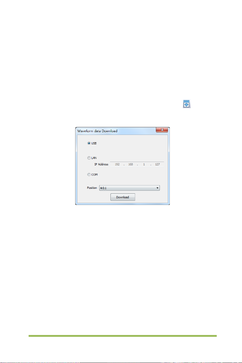
3.3 Outpu t A rbitrary Wav eform
1. Press the Wave Gen button on the front panel to enable the AWG function and enter
the Wave Gen function menu.
2. Connect the device with PC which has installed the WaveEditor software using a
USB cable.
3. Double click the WaveEditor icon to open the program.
4. Select a waveform file or draw an arbitrary waveform; then click the in toolbar
and select waveform data download position to download waveform data to the device.
5. The waveform will output from GEN OUT BNC port.
Also, you can recall ARB format file in USB disk to output a waveform.
1. Press the Wave Gen button on the front panel to enter Wave Gen function menu.
2. Press the Wave softkey, turn the Universal Knob to select Arb1~Arb4 and then
push the knob to confirm.
3. Press Recall softkey and select desired recalled ARB format file in USB disk.
4. The waveform will output from GEN OUT BNC port.
Digital Storage Oscilloscope 71
Page 80

Chapter 4 Troubleshooting
4.1 Problem Settlement
1. If the oscilloscope does not start up at power on, follow these steps:
1) Check the power cord to verify it has been connected properly;
2) Check the power on/off button to ensure it has been pushed;
3) Then restart the oscilloscope.
Contact your local VOLTCRAFT distributor or directly keep touch with VOLTCRAFT
Technical Support department if the oscilloscope still can not be turned on normally.
2. If there is no display of waveforms on the screen when the oscilloscope is
turned on, follow these steps:
1) Check the probe to assure its proper connection to the input BNC;
2) Check the channel switc h ( CH1~CH4 menu buttons) to make sure it has been
turned on;
3) Check the input signal to verify it has been connected to the probe correctly;
4) Affirm that all measured circuits have signals to output;
5) Turn up the magnitude for DC signals with large magnitude;
6) In addition, you may press the Auto Measure button to perform an automatic
detection of signals at first.
Contact VOLTCRAFT Technical Support department in time if there is still no display of
waveforms.
3. If the waveform of the input signal is distorted seriously, follow these steps:
1) Check the probe to assure its proper connection to the channel BNC;
2) Check the probe to assure its good connection to the measured object;
3) Check the probe to verify it has been well calibrated. Otherwise, refer to the
content about calibration described in this manual.
Digital Storage Oscilloscope 72
Page 81

4. If the waveform is rolling continuously on the screen but can not be
triggered, follow these steps:
1) Check the trigger source to make sure it consistent with the input channel;
2) Check the trigger level to assure its correct adjustment. You may push the
TRIGGER LEVEL knob to reset the trigger level back to the center of the signal;
3) Check the trigger mode to confirm it is a right choice for the input signal. The
default trigger mode is edge trigger. However, it is not suitable for all kinds of input
signals.
Digital Storage Oscilloscope 73
Page 82

Chapter 5 General Care and Cleaning
5.1 General Care
Do not put or leave the device in a place where the LCD display will be exposed to
direct sunlight for long periods of time.
Note: To avoid damage to the oscilloscope or probes, do not expose them to sprays,
liquids, or solvents.
5.2 Cleaning
Examine the oscilloscope and probes as often as operating conditions require. To
clean the exterior surface, perform the following steps:
1) Use a lint-free cl oth to remove floating dust on the outside of the oscilloscope and
probes. Take care to avoid scratching the gl abrous displ ay filter.
2) Use a soft cloth dampened with water to clean the oscilloscope. For more efficient
cleaning, you may use an aqueous solution of 75% isopropyl alcohol.
Note: To avoid damage to the surface of the oscilloscope or probes, do not use any
corrosive or chemical cleaning agents.
Digital Storage Oscilloscope 74
Page 83

Appendix A: Technical Specifications
All specifications herein mentioned apply to t he series oscilloscopes. Before c hecking
an oscilloscope from VOLTCRAFT to see if it complies with these specifications, m ake
sure it meets the following conditions:
The oscilloscope must have been operating continuously for twenty minutes
under the specified operating temperature.
The Do Self Cal operation must be performed through the Utility menu if the
operating temperature changes by more than 5℃.
The oscilloscope must be within the factory calibration interval.
All specifications are guaranteed unless noted ‘typical’.
Oscilloscope Specifications
Horizontal
Sample Rate Range
Waveform Interpolation (sin x)/x
Record Length
SEC/DIV Range 2ns/div to 100s/div, in a 1, 2, 5 sequence
Sample Rate and
Delay Time Accuracy
Delta Time Measurement
Accuracy
(Full Bandwidth)
1GS/s(Single-channel); 500MSa/s(Dual-channel);
250MSa/s(Three/Fourchannel)
Maximum 64K samples per single-channel; maximum
32K samples per dual-channel (4K, 32K optional)
±50ppm
Single-shot, Normal mode
± (1 sample interval +100ppm × reading + 0.6ns)
>16 averages
± (1 sample interval + 100ppm × reading + 0.4ns)
Sample interval = s/div ÷ 200
Digital Storage Oscilloscope 75
Page 84

Selectable Analog
Low Frequency Response
l or Average acquisition mode,
±4% for Normal or Average acquisition mode,
Up to 2000 waveforms per second per channel (Normal
Vertical
A/D Converter
VOLTS/DIV Range 500μV/div to 10V/div at input BNC
Position Range
8-bit resolution,
each channel sampled simultaneously
500μV/div to 20mV/div, ±200mV
50mV/div to 200mV/div, ±1V
500mV/div to 2V/div, ±20V
5V/div to 10V/div, ±30V
Bandwidth Limit, typical
(-3db)
20MHz
≤10Hz at BNC
DSO1084 DSO1104 DSO1204 DSO1254
Rise Time at BNC, typical
≤4.4ns <3.5ns ≤1.8ns
±3% for Norma
DC Gain Accuracy
10V/div to 10mV/div
5mV/div to 500μV/div
Note: Bandwidth reduced to 6MHz when using a 1X probe.
Acquisition
Acquisition
Modes
Normal, Peak Detect, Average and HR
Acquisition Rate,
typical
acquisition mode, no measurement)
Single Sequence Acquisition Mode Acquisition Stop Time
Normal,
Peak Detect
Upon single acquisition on all channels
simultaneously
After N acquisitions on all channels
Average
simultaneously, N can be set to 4, 8, 16,
32, 64 or 128
<1.4ns
Digital Storage Oscilloscope 76
Page 85

0.2div × volts/div within ±4 divisions from
Trigger
Mode Auto, Normal
Level
Holdoff Range 20ns ~ 10s
CH1~CH4 ±4 divisions from center of screen
EXT 0~3.3V
Trigger Level
CH1~CH4
center of screen
Accuracy
EXT ± (6% of setting + 40mV)
Edge Trigger
Slope Rising, Falling, Rising&Falling
Source CH1~CH4/EXT
Pulse Width
Polarity Positive, Negative
Condition(When) <, >, ! =, =
Source CH1~CH4
Width Range 8ns ~ 10s
Resolution 8ns
Video Trigger
Signal Standard NTSC, PAL
Source CH1~CH4
Sync ScanLine, LinrNum, OddField, EvenField and AllField
Slope Trigger
Slope Rising, Falling
Condition(When) <, >, ! =, =
Source CH1 ~ CH4
Time Range 8ns ~ 10s
Resolution 8ns
Overtime Trigger
Source CH1~CH4
Polarity Positive, Negative
Time Range 8ns ~ 10s
Digital Storage Oscilloscope 77
Page 86

Resolution 8ns
Window Trigger
Source CH1~CH4
Pattern Trigger
Pattern 0: Lower level; 1: High level;
Level CH1~CH4
Interval Trigger
Slope Rising, Falling
Condition(When) <, >, ! =, =
Source CH1~CH4
Time Range 8ns ~ 10s
Resolution 8ns
Under Amp
Polarity Positive, Negative
Condition(When) <, >, ! =, =
Source CH1~CH4
Time Range 8ns ~ 10s
Resolution 8ns
UART Trigg er
Condition(When) Start, Stop, Data, Parity Error, COM Error
Source (RX/TX) CH1~CH4
Data format Hex
Condition(When) <, >, ! =, =
Data Length 1 byte
Data Bits Width 5 bit, 6 bit, 7 bit, 8 bit
Parity Check None, Odd, Even
Idle Level High, Low
Baud
Rate(Selectable)
Baud Rate (Custom) 300bit/s~334000bit/s
LIN Trigger
110/300/600/1200/2400/4800/9600/14400/19200/38400/576
00/115200/230400/380400/460400 bit/s
Digital Storage Oscilloscope 78
Page 87

Condition(When)
Interval Field, Sync Field, Id field, Sync Id Error, Identifier, Id
and Data
Source CH1~CH4
Data format Hex
Baud Rate
(Selectable)
110/300/600/1200/2400/4800/9600/14400/19200/38400/576
00/115200/230400/380400/460400 bit/s
Baud Rate (Custom) 300bit/s~334000bit/s
CAN Trigger
Start Bit, Remote F rame, D ata Frame Id, F rame Id,
Condition(When)
DataFrame Id A, Error Frame, All Error, Ack Error, Overload
Fram
Source CH1~CH4
Data format Hex
Baud Rate
(Selectable)
10000, 20000, 33300, 500000, 62500, 83300, 100000,
125000, 250000, 500000, 800000, 1000000
Baud Rate (Custom) 5kbit/s~1Mbit/s
SPI Trigger
Condition Data
Source
(CS/CLK/Data)
CH1~CH4
Data format Hex
Data Length 4, 8, 16, 24, 32
IIC Trigger
Source (SDA/SCL) CH1~CH4
Data format Hex
Data Index 0~7
When(Condition) Start, Stop, No Ack, Address, Data, Restart
Inputs
Inputs
Input Coupling DC, AC or GND
Digital Storage Oscilloscope 79
Page 88

FRR, FFF, FRF, FFR, LRR,
Input Impedance,
DC coupled
Probe
Attenuation
Supported Probe
Attenuation
Factors
Overvoltage
Category
Maximum Input
Voltage
Measurements
Cursors
Automatic
Measurements
1MΩ±2% in parallel with 20pF±3pF
1X, 10X
1X, 10X, 100X, 1000X
300V CAT II
300V
RMS
(10X)
Voltage difference between cursors: △V
Time difference between cursors: △T
Reciprocal of △T in Hertz (1/ΔT)
Frequency, Period, Average, Pk-Pk, RMS, PeriodRms, Min,
Max, RiseTime, FallTime, + Width, - Width, + Duty, - Duty,
Vbase, Vtop, Vmid, Vamp, Overshoot, Preshoot, PeriodAvg,
FOVShoot, RPREShoot, BWidth,
LRF, LFR and LFF
General Specifications
Display
Display Type 7 inch 64K color TFT (diagonal liquid crystal)
Display
Resolution
800 horizontal by 480 vertical pixels
Display Contrast Adjustable
Probe Compensator Output
Output Voltage,
typical
About 2Vpp into ≥1MΩ load
Frequency, 1kHz
Digital Storage Oscilloscope 80
Page 89

typical
Power Supply
Supply Voltage
Power
Consumption
100-120VAC
120-240VAC
<30W
Fuse T, 3.15A, 250V, 5x20mm
Environmental
Operating
Temperature
Operation
Humidity
Storage
Temperature
Storage
Humidity
0 to 50 °C (32 to 122 °F)
≤90% relative humidity
-40 to +71 °C (-40 to 159.8 °F)
≤60% relative humidity
Cooling Method Convection
Altitude Operating and Nonoperating 3,000m (10,000 feet)
Random Vibration
Nonoperating
Mechanical
Shock
Operating 50g, 11ms, half sine
Mechanical
Dimension 318 x 110 x 150mm(L x W x H)
Weight 2900g
(±10%), 45Hz to 440Hz, CAT Ⅱ
RMS
(±10%), 45Hz to 66Hz, CAT Ⅱ
RMS
0.31g
RMS
10 minutes on each axis
2.46g
RMS
10 minutes on each axis
from 50Hz to 500Hz,
from 5Hz to 500Hz,
Digital Storage Oscilloscope 81
Page 90

Arbitrary Waveform Generator Mode
(DSO1084F,DSO1104F,DSO1204F,DSO1254F)
Sine: 0.1Hz~25MHz
Waveform Frequency
Amplitude
DAC 2K~200MHz adjustable
Frequency Resolution 0.10%
Channel 1CH waveform output
Waveform Depth 4KSa
Vertical Resolution 12 bit
Frequency Stability <30ppm
Output Impedance 50 Ω
Square: 0.1Hz~10MHz
Ramp: 0.1Hz~1MHz
EXP: 0.1Hz~5MHz
5mV~3.5Vp-p(50Ω)
10mV~7Vp-p(High impedance)
Appendix B: Accessories
All the following accessories are available by contacting your local VOLTCRAFT
distributor.
Standard Accessories
• Probe×4 (1.5m), 1:1, (10:1) Passive Probes
• A Power line
• A USB Line
• A BNC to BNC(Only for the scopes with waveform generator function)
• A PC software CD of the oscilloscope
•
Digital Storage Oscilloscope 82
Page 91

Appendix C Harmful and Poisonous
Substances or Elements
Harmful and poisonous substances or elements 1
Component2 Pb Hg Cd Cr(Vi) PBB PBDE
Shell and Chassis X 0 0 X 0 0
Display Module X X 0 0 0 0
Circuit Board X 0 0 X 0 0
Power Supply X 0 0 X 0 0
Electric Wire and Cable
Assembly
Connector X 0 0 X 0 0
Fastener and Installed
Hardware
Other Accessories (including
probes)
Others 0 0 0 0 0 0
‘X’ means that at least the content of this poisonous and harmful substance in a
homogeneous material of this component exceeds the limit specified in the SJ/T
11363-2006 standard.
‘0’ indicates that the content of this poisonous and harmful substance in all
homogeneous materials of this component is refrained under the limit stated in the
SJ/T 11363-2006 standard.
This component list contains components approved in the file ‘Management
Measures’.
X 0 0 0 0 0
X 0 X X 0 0
X 0 0 X 0 0
Digital Storage Oscilloscope 83
Page 92

Appendix D To replace the fuse
The fuse of the series of scope is replaceable.
Fuse Rating: T, 3.15A, 250V, 5x20mm
Please refer to the following to replace it.
Warning: Remove power cord & all test probe before open the housing and replace
the fuse.
1. Remove all t he screws on the shell, and separate the rear shell from other part.
Digital Storage Oscilloscope 84
Page 93

2. Remove all t he screws on the metal cover, separate metal cover from other part.
3. Remove all the screws on the power shield, then rem ove it. You can see the fuse
on the power board. And replace a new fuse with the same specification.
Digital Storage Oscilloscope 85
Page 94

Sourcecode download
Appendix E Open Source Information
General Information:
Kernel Version Linux3.2.35
Supported File system ubi, Fat32
Buzzer Driver, DMA Driver, FPGA Driver, I2C Driver,SPI
Drivers
Linux Applications Busybox1.18.4 ,gnupg1.4.11
U_boot Version Vivi_3.2.35
website
License:
GNU GENERAL PUBLIC LICENSE
Copyright (C) 1989, 1991 Free Software Foundation, Inc.,
51 Franklin Street, Fifth Floor, Boston, MA 02110-1301 USA
Everyone is permitted to copy and distribute verbatim copies of this license document,
but changing it is not allowed.
Preamble
The licenses for most software are designed to take away your freedom to share and
change it. By contrast, the GNU General Public License is intended to guarantee your
freedom to share and change free software--to make sure the software is free for all its
users. This General Public License applies to most of the Free Software Foundation's
software and to any other program whose authors commit tousing it. (Some other
Free Software Foundation software is covered by
Driver, IO-bank Dri ver, USB Host Driver, LCD Driver,
USB massstorage、gadget Driver
http://www.produktinfo.conrad.com
Versi on 2, June 1991
Digital Storage Oscilloscope 86
Page 95

the GNU Lesser General Public License instead.) You can apply it to your programs,
too.
When we speak of free software, we are referring to freedom, notprice. Our
General Public Licenses are designed to make sure that you have the freedom to
distribute copies of free software (and charge for this service if you wish), that you
receive source code or can get it if you want it, that you can change the software or use
pieces of it in new free programs; and that you know you can do these things.
To protect your rights, we need to make restrictions t hat forbid anyone to deny you
these rights or to ask you to surrender the rights. These restrictions translate to certain
responsibilities for you if you distribute copies of the software, or if you modify it.
For example, if you distribute copies of such a program, whether gratis or for a fee,
you must give the recipients all the rights that you have. You must make sure that they,
too, receive or can get the source code. And you must show them these terms so
they know their rights.
We protect your rights with two steps: (1) copyright the software, and (2) offer you
this license which gives you legal permission to copy, distribute and/or modify the
software.
Also, for each author's protection and ours, we want to make certain that everyone
understands that there is no warranty for this free software. If the software is modified
by someone else and passed on, we want its recipients to know that what they have is
not the original, so that any problems introduced by others will not reflect on the original
authors' reputations.
Finally, any free program is threatened constantly by software patents. We wish to
avoid the danger that redistributors of a free program will individually obtain patent
licenses, in effect making the program proprietary. To prevent this, we have made it
clear that any patent must be licensed for everyone's free use or not licensed at all.
Digital Storage Oscilloscope 87
Page 96

The precise terms and conditions for copying, distribution and modification follow.
GNU GENERAL PUBLIC LICENSE
TERMS AND CONDITIONS FOR COPYING, DISTRIBUTION AND MODIFICATION
0. This License applies to any program or other work which contains a notice placed
by the copyright holder saying it may be distributed under the terms of this General
Public License. The "Program", below, refers to any such program or work, and a
"work based on the Program" means either t he Program or any derivative work under
copyright law: that is to say, a work containing the Program or a portion of it, either
verbatim or with modifications and/or translated into another language. (Hereinafter,
translation is included without limitation in the term "modification".) Each licensee is
addressed as "you".
Activities other than copying, distribution and modification are not covered by this
License; they are outside its scope. The act of
running the Program is not restricted, and the output from the Program is covered only
if its contents constitute a work based on the Program (independent of having been
made by running the Program). Whether that is true depends on what the Program
does.
1. Y ou may copy and distribute verbatim copies of the Program's source code as you
receive it, in any medium, provided that you conspicuously and appropriately publish
on each copy an appropriate copyright notice and disclaimer of warranty; keep intact all
the notices that refer to this License and to the absence of any warranty; and give any
other recipients of the Program a copy of this License along with the Program.
You may charge a fee for the physical act of transferring a copy, and you may at your
option offer warranty protection in exchange for a fee.
Digital Storage Oscilloscope 88
Page 97

2. You may modify your copy or copies of the Program or any portion of it, thus
forming a work based on the Program, and copy and distribute such modifications or
work under the terms of Section 1 above, provided that you also meet all of these
conditions:
a) You must cause the modified files to carry prominent notices stating that you
changed the files and the date of any change.
b) You must cause any work that you distribute or publish, that in whole or in part
contains or is derived from the Program or any part thereof, to be licensed as a whole
at no charge to all third
parties under the terms of this License.
c) If the modified program normally reads commands interactively when run, you
must cause it, when started running for such interactive use in the most ordinary way,
to print or display an announcement including an appropriate copyright notice and
a notice that there is no warranty (or else, saying that you provide a warranty) and that
users may redistribute the program under these conditions, and telling the user
how to view a copy of this License. (Exception: if the Program itself is interactive but
does not normally print such an announcement, your work based on the Program is not
required to print an announcement.)
These requirements apply to the modified work as a whole. If identifiable sections of
that work are not derived from the Program, and can be reasonably considered
independent and separate works in themselves, then this License, and its terms, do not
apply to those sections when you distribute them as separate works. But when you
distribute the same sections as part of a whole which is a work based on the Program,
the distribution of the whole must be on the terms of
this License, whose permissions for other licensees extend to the entire whole, and
thus to each and every part regardless of who wrote it.
Digital Storage Oscilloscope 89
Page 98

Thus, it is not the intent of this section to claim rights or contest your rights to work
written entirely by you; rather, the intent is to exercise the right to control the distribution
of derivative or collective works based on the Program.
In addition, mere aggregation of another work not based on the Program with the
Program (or with a work based on the Program) on a volume of a storage or distribution
medium does not bring the other work under the scope of this License.
3. You may copy and distribute the Program (or a work based on it, under Section 2)
in object code or executable form under the terms of Sections 1 and 2 above provided
that you also do one of the following:
a) Accompany it with the complete corresponding machine-readable source code,
which must be distributed under the terms of Sections 1 and 2 above on a medium
customarily used for software interchange; or,
b) Accompany it with a written offer, valid for at least three years, to give any third
party, for a charge no more than your cost of physically performing source distribution,
a complete
machine-readable copy of the corresponding source code, to be distributed under
the terms of Sections 1 and 2 above on a medium customarily used for software
interchange; or,
c) Accompany it with the information you received as to the offer to distribute
corresponding source code. (This alternative is allowed only for nonc ommercial
distribution and only if you received the program in object code or executable form
with such an offer, in accord with Subsection b above.)
The source code for a work means the preferred form of the work for making
modifications to it. For an executable work, complete source code means all the
source code for all modules it contains, plus any associat ed interf ace definiti on fil es,
plus the scripts used to c ontrol compilation and installation of the executable.
Digital Storage Oscilloscope 90
Page 99

However, as a special exception, the source code distributed need not include anything
that is normally distributed (in either source or binary form) with the major components
(compiler, kernel, and so on) of the operating syst em on which the executable runs,
unless that component itself accompani es the executable.
If distribution of executable or object code is made by offering access to copy from a
designated place, then offering equivalent access to copy the source code from the
same place counts as
distribution of the source code, even though third parties are not compelled to copy the
source along with the object code.
4. You may not copy, modify, sublicense, or distribute the Program except as
expressly provided under this License. Any attempt otherwise to copy, modify,
sublicense or distribute the Program is void, and will automatically terminate your rights
under this License. However, parties who have received copies, or rights, from you
under this License will not have their licenses terminated so long as such parties
remain in full compliance.
5. You are not required to accept this Lic ense, since you have not signed it.
However, nothing else grants you permission to modify or distribute the Program or its
derivative works. These actions are prohibited by law if you do not accept this
License. Therefore, by modifying or distributing the Program (or any work based on
the Program), you indicate your acceptance of this License to do so, and all its terms
and conditions for copying, distributing or modifying the Program or works based on it.
6. Each time you redistribute the Program (or any work based on the Program), the
recipient automatically receives a license from the original licensor to copy, distribute or
modify the Program subject to these terms and conditions. You may not impose any
further restrictions on the recipients' exercise of the rights granted herein. You are not
responsible for enforcing compliance by third parties to this License.
Digital Storage Oscilloscope 91
Page 100

7. If, as a consequence of a court judgment or allegation of patent infringement or for
any other reason (not limited to patent issues), conditions are imposed on you (whether
by court order, agreement or otherwise) that contradict the conditions of this License,
they do not excuse you from the conditions of this License. If you cannot distribute so
as to satisfy simultaneously your obligations under this License and any other pertinent
obligations, then as a consequence you
may not distribute the Program at all. For example, if a patent license would not
permit royalty-free redistribution of the Program by all those who receive copies directly
or indirectly through you, then the only way you could satisfy both it and this License
would be to refrain entirely from distribution of the Program.
If any portion of this section is held invalid or unenforceable under any particular
circumstance, the balance of the section is intended to apply and the section as a
whole is intended to apply in other
circumstances.
It is not the purpose of this section to induce you to infringe any patents or other
property right claims or to contest validity of any such claims; this section has the sole
purpose of protecting the
integrity of the free software distribution system, which is implemented by public
license practices. Many people have made generous contributions to the wide range
of software distributed through that syst em in relianc e on consistent applic ation of that
system; it is up to the author/donor to decide if he or she is willing to distribute software
through any other system and a licensee cannot
impose that choice.
This section is intended to make thoroughly clear what is believed to be a consequence
of the rest of this License.
8. If the distribution and/or use of the Program is restricted in certain countries either
by patents or by copyrighted interfaces, the original copyright holder who places the
Program under this License may add an explicit geographical distribution limitation
Digital Storage Oscilloscope 92
 Loading...