

Vollrath 72723019, 72729017, 72729019, 7286002, 7286100 Installation Manual
ENGLISH
Operator’s Manual
English, Spanish, French
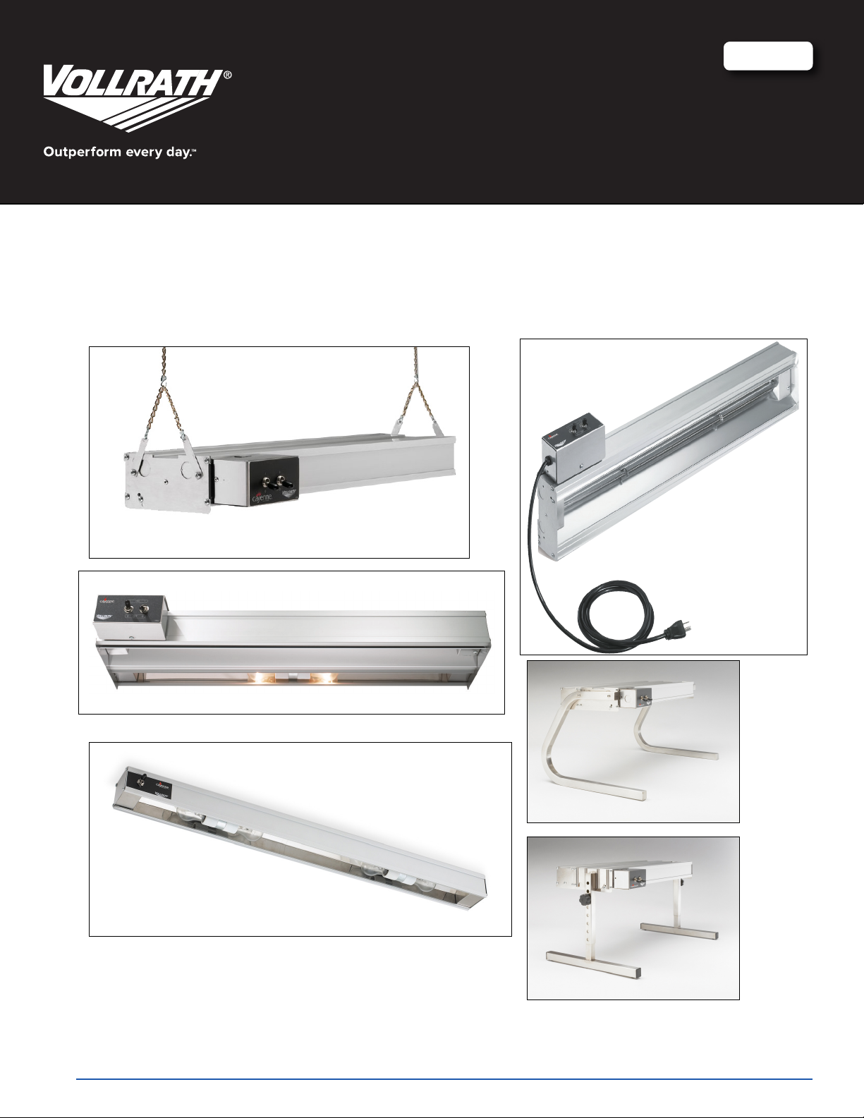
CAYENNE® HEAT AND LIGHT STRIPS
RegisteR youR pRoduct on-line at www.vollRath.com
Thank you for purchasing this Vollrath Food Processing Equipment. Before operating the equipment, read and familiarize yourself with
the following operating and safety instructions. SAVE THESE INSTRUCTIONS FOR FUTURE REFERENCE. Save the original box and
packaging. Use this packaging to ship the equipment if repairs are needed.
Item No. 17030-1 ml Rev 09/14
safety pRecautions
To ensure safe operation, read the following statements and understand
their meaning. This manual contains safety precautions which are
explained below. Please read carefully.
WARNING
Warning is used to indicate the presence of a hazard that can cause
severe personal injury, death, or substantial property damage if the
warning is ignored.
CAUTION
Caution is used to indicate the presence of a hazard that will or can
cause minor personal injury or property damage if the caution is
ignored.
NOTE
Note is used to notify people of installation, operation, or maintenance
information that is important but not hazard-related.
For Your Safety!
These precautions should be followed at all times. Failure to follow
these precautions could result in injury to yourself and others or damage
the equipment.
To reduce risk of injury or damage to the unit:
Use only grounded electrical outlets or circuits matching the nameplate
rated voltage.
Unit should only be used in a at, level position.
Turn off unit and let it cool before cleaning or moving.
ENGLISH
Do not operate unattended.
unit installation cleaRances
Do not use extension cords, power strips or surge protectors with this
unit.
Install with distances specied in the Unit Installation section of this
manual. Minimum distance to the following surfaces.
Combustible surroundings 5” Sides 2” Top
Non Combustible surroundings 1” Sides 1” Top
Setback from edge of pass-through 8” from any edge
Units that require wiring for installation must follow National Electrical
Code (NEC) standards and local ordinances.
Only use coated light bulbs that meet NSF standards and are
specically designed for foodservice areas. Breakage of bulbs that are
not coated could cause injury or contaminate food.
Do not place materials on or allow combustible materials to come in
contact with unit.
There are no serviceable parts in this unit. Contact a Vollrath
Authorized Service Agent for service.
Authorized service agent must use genuine Vollrath replacement parts.
Failure to do so will void warranty and may cause a safety hazard.
Do not spray controls or outside of unit with liquids or cleaning agents.
Units that require a circuit breaker larger than 20 amps must have
separate circuit for the lighting circuit that is less than 20 amps.
function and puRpose
Heat Strips = These units are intended to be used as a heat source to help
maintain food at safe temperatures until served. They are not intended
or designed to cook raw food or to reheat prepared food. Food must be
prepared and placed in food stations at proper temperatures.
Light Strips = These units are intended to illuminate food serving display
areas or food preparation areas.
unpacking the equipment and initial setup
Carefully remove crating or packaging materials from the unit. Dispose of all
packaging ,materials in an environmentally responsible manner.
WARNING
Fire Hazard.
Do not install unit near combustible material. Do not
place combustible material under or on top of unit.
Discoloration or combustion could occur.
WARNING
Electrical Shock Hazard.
Keep water and other liquids from entering the
inside of the unit. Liquid inside the unit could cause
an electrical shock. Unit must be installed by
qualied personal in accordance with all local and
national ordinances. Do not use a power cord that
has been modied or damaged.
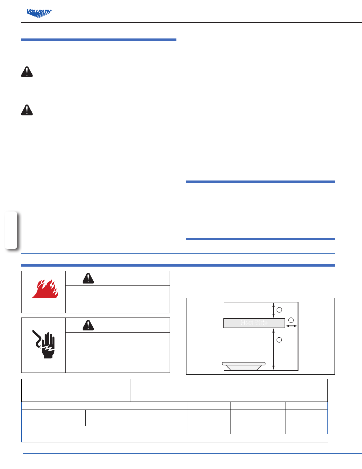
Single
Minimum Clearances
A Top of strip to surface above (minimum)
B Bottom of strip to surface
below
C Side of strip to adjacent surface (minimum)
Setback from front opening on pass through application: maximum of 8" (20.3 cm)
Medium Wattage 11" (27.9 cm) 13" (33.0 cm) 18" (45.7 cm) 20" (50.8 cm)
High Wattage 16" (40.6 cm) 16" (40.6 cm) 24" (60.9 cm) 25" (63.5 cm)
Non-Combustible
Surface
1" (2.5 cm) 2" (5.1 cm) 1" (2.5 cm) 2" (5.1 cm)
1" (2.5 cm) 5" (12.7 cm) 1" (2.5 cm) 5" (12.7 cm)
This unit must be installed by qualied personal in compliance with electrical
codes. The following distances must be kept between the unit and the
surrounding surfaces for safe operation. It is recommended that two (2) or
more people assist with the installation of this unit.
A
C
B
Dual
Combustible
Surface
Single
Combustible
Surface
Heat Strip
Dual
Non-Combustible
Surface
2
OperatOr’s Manual
NOTE:
This unit must be installed in an area that will not be affected by the heat
3. Mount the brackets and unit to a suitable surface using holes (E) and
suitable hardware.
from the unit. Damage to solid surface counter tops or other materials in
the heat zone of this product are not covered under warranty.
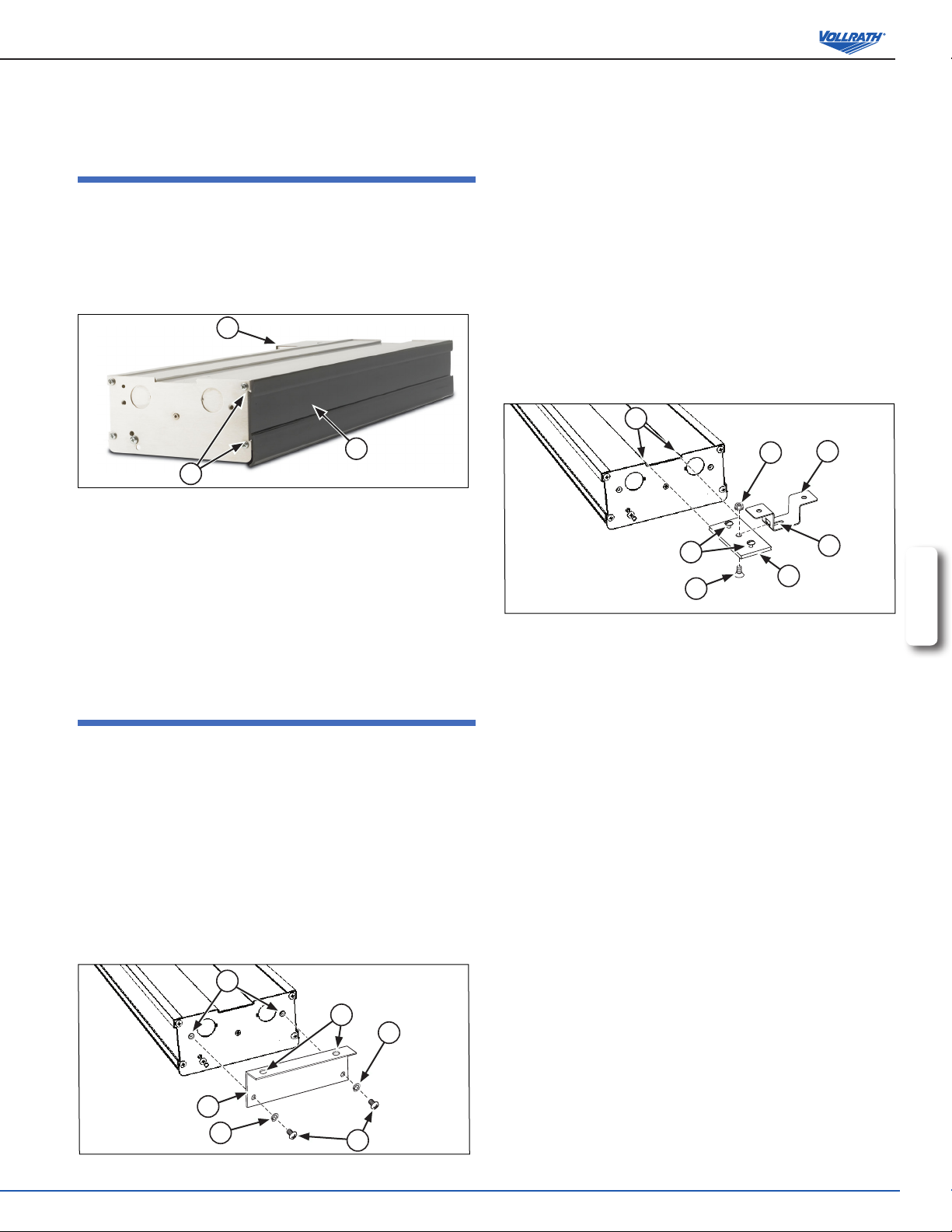
kool-touch® tRim installation
The Kool-Touch® trim option is shipped separately. It will need to be installed
on the unit. We recommend that this option be installed before the unit is
mounted.
1. Beginning on the side that does not have the control box (A), slide the
Kool-Touch® (B) panel into position by starting at one end of the unit. Slide
the Kool-Touch® panel in the channel (C) on the side of the unit until it is in
place. (Ganged units will require two pieces trimmed to t). See Figure 1.
A
centeR mount installation
Top mount brackets may be purchased as an option for direct-wired units.
The brackets are available in 1” height or 2” height. Dual units require
brackets on each unit.
NOTE:
For units longer than 72”, a minimum of three (3) mounting points
consisting of the two ends and the center of the unit must be used.
1. Access the area the unit will be mounted in and mark the location the
center mount brackets will be mounted. Make sure the material the unit
will be mounted to will support the weight of the unit.
2. The brackets must be located near the ends of the unit for greatest
stability.
3. Mount the hanging bracket (A) with the “T” slot cutout, in the locations
identied in step 1. Figure 3.
D
B
C
Figure 1. Installation of Kool-Touch® Panels.
2. The side of the unit that has the control box will need to be trimmed.
Measure the area that is to be covered by the Kool-Touch® panel.
3. Mark the length to be covered on the Kool-Touch® panel.
4. Place a damp soft cloth under the end of the Kool-Touch® panel to be cut
to prevent the Kool-Touch® panel from scratching or slipping while it is
being cut.
5. Using a hacksaw with a ne metal or plastic blade, slowly cut the panel to
length.
6. Install the panel on the unit in the same manner as the opposite side.
unit installation - diRect wiRe mounting
Figure 3. Installing Center Mount Brackets.
4. Loosen the two screws (B) located in the center of the at channel
plates (C) far enough so they do not protrude out of the bottom of the
plate.
5. Slide the channel plates (C) into the channel (D) on the top of the unit.
6. Measure the distance from the center points of the hanging brackets
top mount installation
Top mount brackets may be purchased as an option for direct-wired units. The
brackets are available in 1” height or 2” height. Dual units require two sets of
brackets.
NOTE:
Top mount brackets may not be used with units longer than 72”.
1. Access the area the unit will be mounted in and mark the location the
center mount brackets will be mounted. Make sure the material the unit
will be mounted to will support the weight of the unit.
2. Secure the top mount bracket (A) to the mounting holes (B) using
lockwashers (C) and screws (D). Repeat on the other end. See Figure 2.
(A) and slide the channel plates (C) in the channel (D) on the top of the
unit so the center screws (E) in the channel plate (C) match the distance
between the center of the “T” slot (G) in the brackets (A).
7. Tighten the two outside screws (B) in the channel plate (C) to lock the
channel plate in position.
8. Loosen the nut (F) in the center of the channel plate (C) but DO NOT
REMOVE.
9. Raise the unit and align the nut (F) in the center of the channel plate (C)
with the “T” in the bracket (A) mounted in step 2.
10. Slide the nut (F) through the “T” slot and TIGHTEN THE NUT to keep the
unit in place. THE NUT MUST BE TIGHTENED TO PREVENT THE UNIT
FROM SLIPPING OUT OF THE BRACKET.
F
B
E
A
G
C
ENGLISH
B
A
C
Figure 2. Installing Top Mount Brackets.
chain mount installation
E
C
D
NOTE: Units over 72” in length, must use the center mounting point.
1. The unit is shipped with mounting tabs (A) located on each end of
the unit. For units that are longer than 72”, three (3) mounting points
consisting of the two ends and the center of the unit must be used. See
Figure 4.
2. Loosen the screws (B) holding the mounting tabs in place but do not
remove. Rotate tabs (A) to an upright position and the attach chain to
holes (C). The chain must support each side of each end of the unit
evenly.
OperatOr’s Manual
3
3. Hang chain from an appropriate hanging point directly over the area to be
kept warm. Make sure the hanging point is adequate for the total weight of
unit installation - coRded mounting
the unit and chain.
4. Adjust height of the unit making sure it is level and each point is supporting
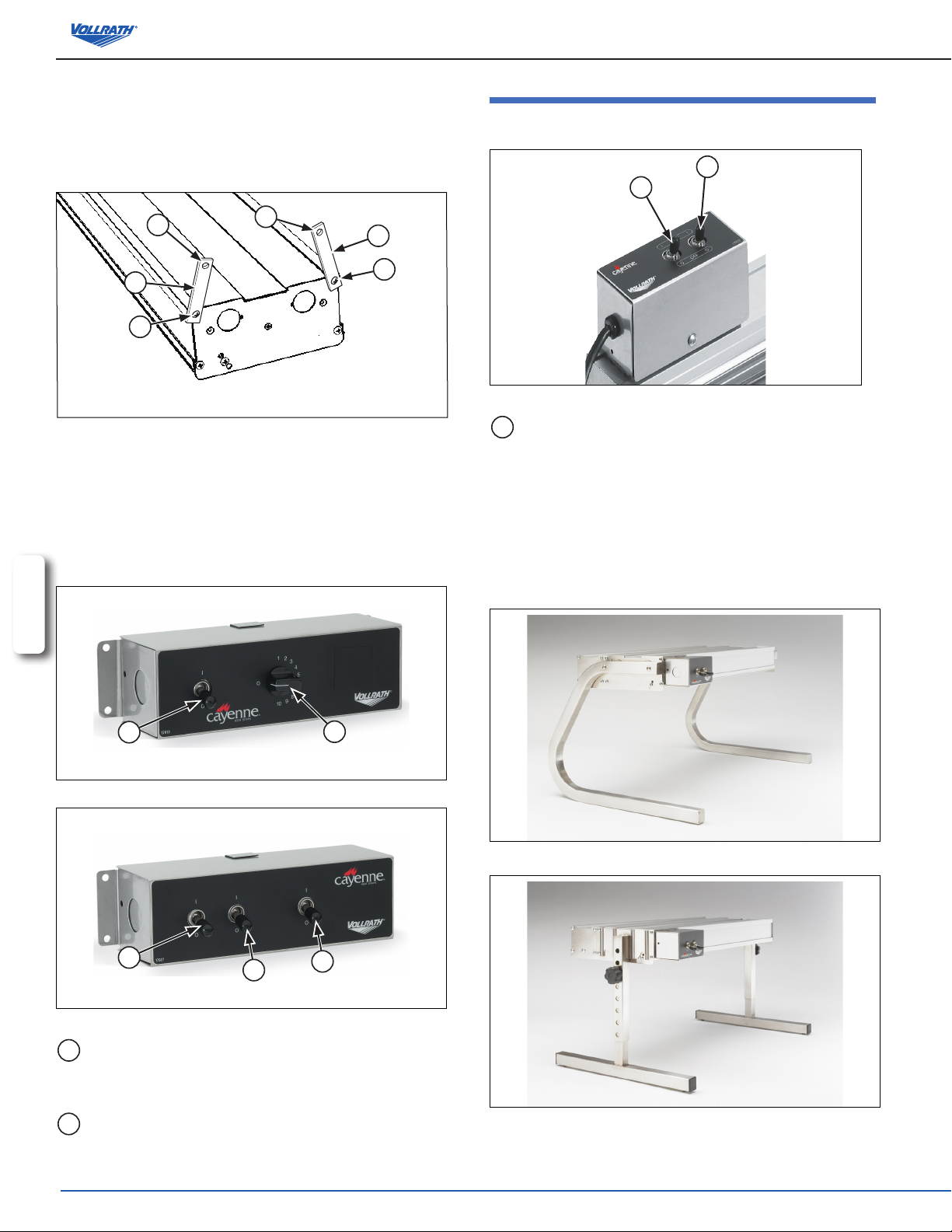
on BoaRd toggle contRols
the weight of the unit evenly.
5. Tighten screws (B) to secure the mounting tabs.
A
A
C
A
B
C
A
B
Figure 4. Chain Mount Installation.
Remote mounting of contRol(s)
NOTE: Installations must be in accordance with National Electrical Code
(NEC) regulations.
Control boxes must be mounted securely to surfaces using proper hardware.
Mount the control box(es) in such a way they will not be bumped or accidently
switched on or off.
ENGLISH
Figure 7. On Board Toggle Control with Switches
A
ON/OFF Toggle Switch. Move the toggle switch to the up
position for “ON”. Move the toggle switch to the down position
for “OFF”.
mounting options
NOTE: UL requires all cord and plug heat strips, from all
manufacturers be mounted on legs. All heat strips are custom ordered
and therefore cannot be cancelled or returned per Vollrath Terms and
Conditions.
A
B
Figure 5. Control Panel with Switch and Innite Control.
A
A
A
Figure 6. Control Panel with Switches
A
ON/OFF Toggle Switch. Move the toggle switch to the up position
for “ON”. Move the toggle switch to the down position for “OFF”.
The switch(es) may operate a heating element(s) or light(s).
B
INFINITE HEAT CONTROL. Rotate the INFINITE HEAT
CONTROL off zero “0” to turn control on. Rotate to desired heat.
Figure 8. Stainless Steel C-Leg Stand - 13” (33 cm)
Figure 9. Stainless Steel T-Leg Stand -
Adjustable 8 to 15” (22.8 to 38.1 cm)
4
OperatOr’s Manual
opeRation
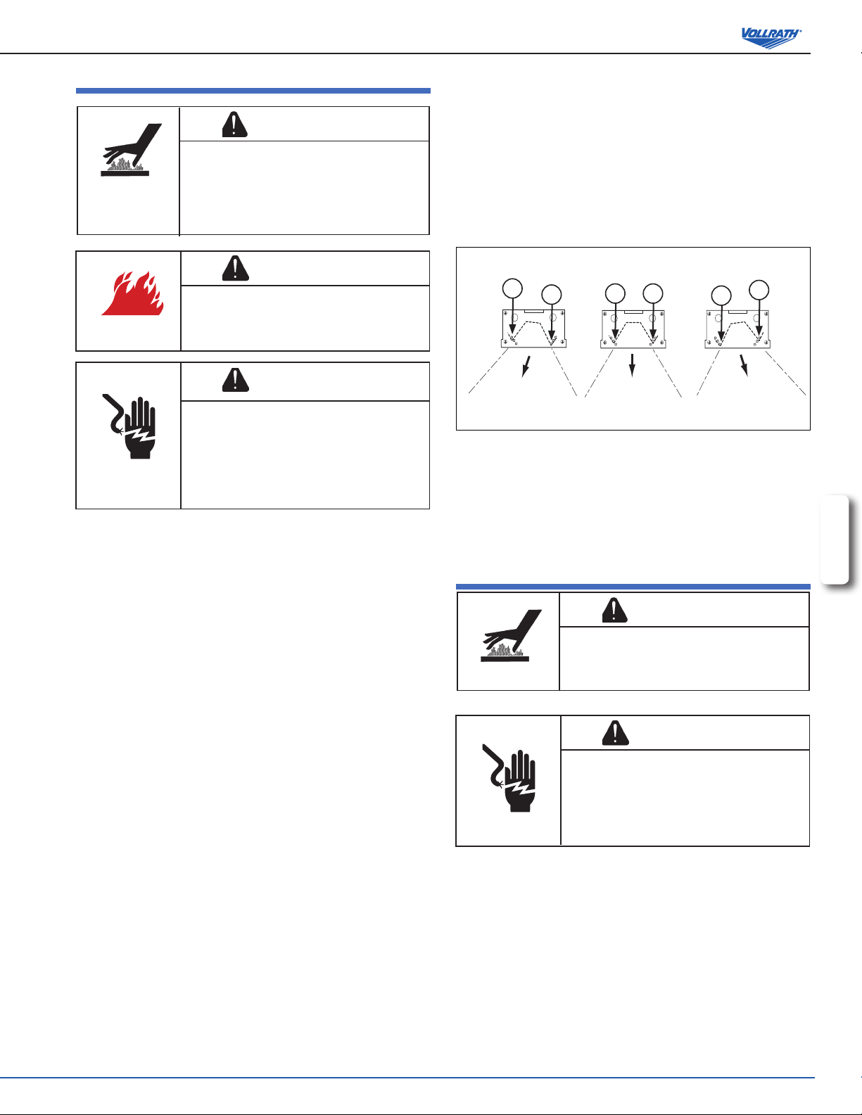
adjusting the heat ReflectoR
The heat strip units have been equipped with a directional heat reector to
allow the heat zone to be directed to best suite each application.
WARNING
Burn Hazard.
Do not touch heating surfaces, liquid, or while unit
is heating or operating.
and liquids can burn skin. Use gloves, mitts or
pot holders if it is necessary to handle hot pans,
plates and equipment.
Hot food, surfaces, steam
1. Turn the switch(es) to the “OFF” position(s). Allow the unit to cool
completely before continuing.
2. Make sure unit is cool. This is for safety and the reector can be moved
more easily when the unit is at room temperature.
3. Remove the small screws (A) from the holes on the end alignment
plates. There is one screw on each side of the end plate that secures the
reector. See Figure 10.
WARNING
Fire Hazard.
Do not install unit near combustible material. Do not
place combustible material under or on top of unit.
Discoloration or combustion could occur.
WARNING
Electrical Shock Hazard.
Keep water and other liquids from entering the
inside of the unit. Liquid inside the unit could cause
an electrical shock. Unit must be installed by
qualied personal in accordance with all local and
national ordinances. Do not use a power cord that
has been modied or damaged.
NOTE: Certain containers such as foam or plastic may melt if left in the
heat zone. Also, food left in the heat zone may begin to dry if left in the
heat zone for an extended time.
1. Make sure there are no combustible materials in contact or near the
food-warming unit.
2. Turn the heat switch(es) to the “ON”position or set the INFINITE HEAT
CONTROL to desired setting. Allow the unit to preheat for approximately
15 minutes before placing food in the heat zone.
3. If the unit is equipped with lights, switch the lights on.
4. Place food items to be kept warm in the heat zone. Regularly check the
food temperature. Adjust controls as necessary. See Note:
NOTE:
Monitor food temperature closely for food safety. The United States
Public Health Service recommends that hot food be held at a minimum
of 140 ºF (60 ºC) to help prevent bacteria growth. Maintain correct water
level and temperature setting. Periodically remove food container and
check the water level. Add water in needed.
5. When not in use turn the heat switch(es) to the “OFF” position or rotate
the innite heat control to the zero (0) position. Turn the lights to the
“OFF” position.
Figure 10. Reector Positions.
4. Pivot the reector in the desired direction.
5. There are 3 alignment screw holes to choose from that are located on
the outside end of the unit. Align the screw hole in the reector end
with the appropriate hole in the end plate for the desired direction of the
reector.
6. Place the screws in the appropriate location and tighten.
cleaning
1. Turn the power switch(es) off. Turn the light switch(es) off. Allow the unit
to completely cool.
2. Wipe the unit exterior with a clean damp cloth.
3. Do not use abrasive materials, scratching cleansers or souring pad to
clean the unit. These can damage the nish.
4. Thoroughly wipe off any mild soap or chemical cleaners. Residue could
corrode the surface of the unit.
A
A
A
A
A
A
ENGLISH
WARNING
Burn Hazard.
Hot surfaces can burn the skin
completely before cleaning.
. Allow unit to cool
WARNING
Electrical Shock Hazard.
Do not spray unit or controls with liquid or cleaning
product.
Liquid could enter the electrical compartment and
cause a short circuit or electric shock.
OperatOr’s Manual
5
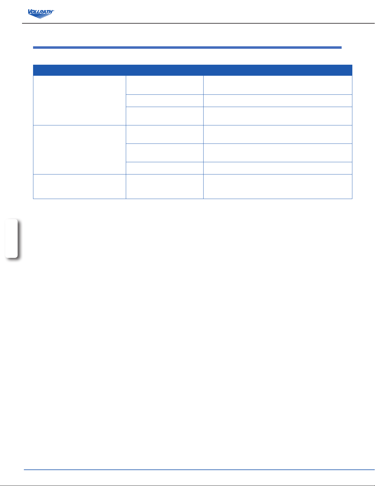
tRouBleshooting
All procedures are to be carried out by qualied individuals. This may include Vollrath Authorized Service Agents or special trained personnel adhering to
local codes.
Problem It might be caused by Course of Action
Unit is switched “ON” but there is no heat.
The unit is on, but low heat.
Lights or switches burn out after a short
time.
ENGLISH
No power to the unit.
Defective switch. Replace the switch.
Wiring or heating element problem.
Unit is mounted too high above the
heating zone.
Excess cold air circulation around
heating zone or unit.
Incorrect power supply (low). Check that the power supply matching the nameplate rated voltage.
Check mounting height. If unit is to
low, the unit will over heat.
Check that there is power to the outlet. Reset circuit breaker if
necessary.
Check that all wire are good. Check that the element connection is
good. Check element and replace if necessary.
Re-mount unit lower, placing heat closer to heating zone. See Unit
Installation Clearances chart on page 2.
Restrict or redirect air movement away from heating zone or unit.
Check that the unit is mounted as specied in the Unit Installation
Clearances chart on page 2. If unit is not at the correct height,
remount unit.
6
OperatOr’s Manual
Black
White
Optional
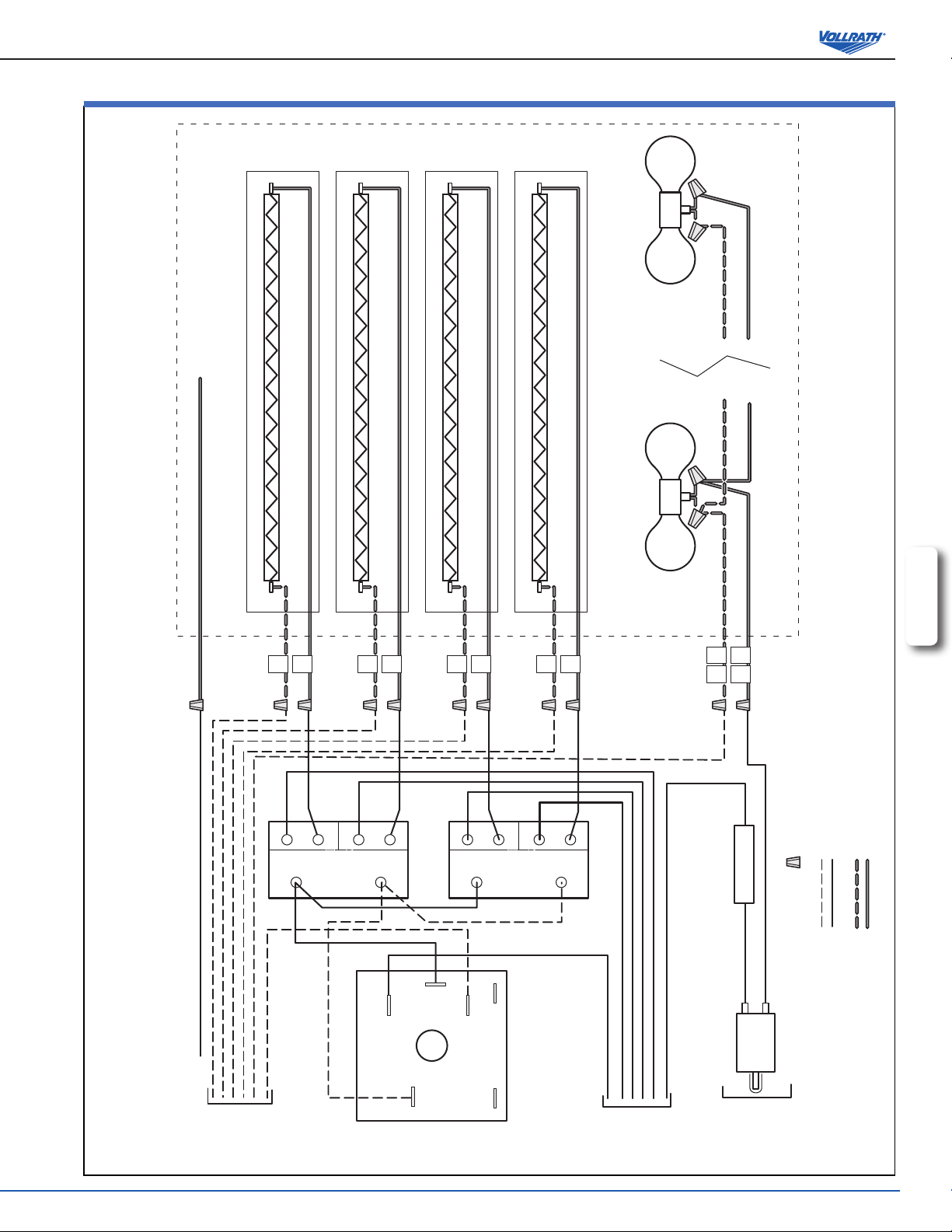
120 Volt Heater W/Infinate Control Assembly Wiring Diagram
electRical diagRam 120 volt heateR ~ infinite contRol
Ground Wire
Heater AssemblyControl Assembly
Heating Element #1
Heating Element #2
120 Volt Optional Lights
Heating Element #3
Heating Element #4
120V
120V
Up to 6 Light Fixtures Wired in Parellel
Green
ENGLISH
1
2
3
Relay
Power
4
5
6
7
Relay
Power
8
1 1
1 2
Ceramic Wire Nuts
200 °C Temprature Rated Wire
450 °C Temprature Rated Wire
Fuse
above 16 Amps
Use W/Lighted units
Green
N
L2
H1
H2
L1
P2 P1
L1
Light
Switch
OperatOr’s Manual
7
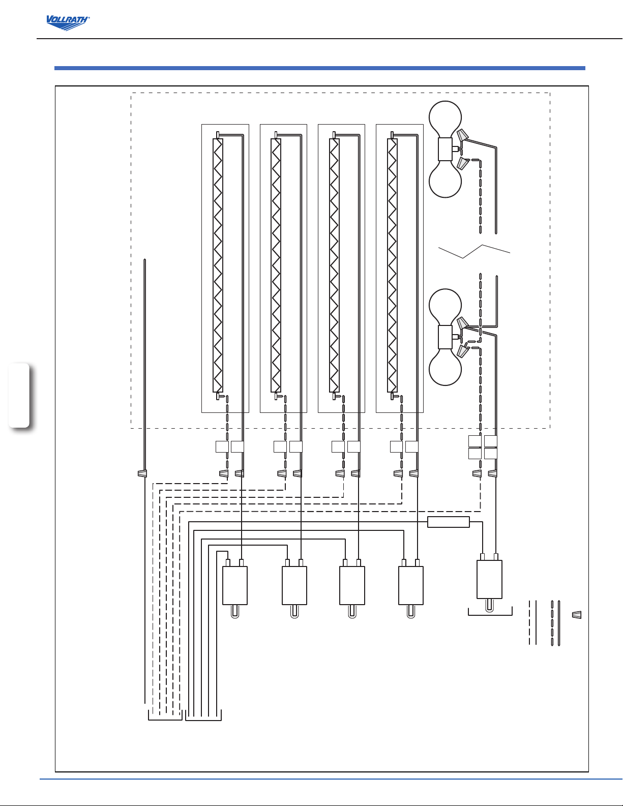
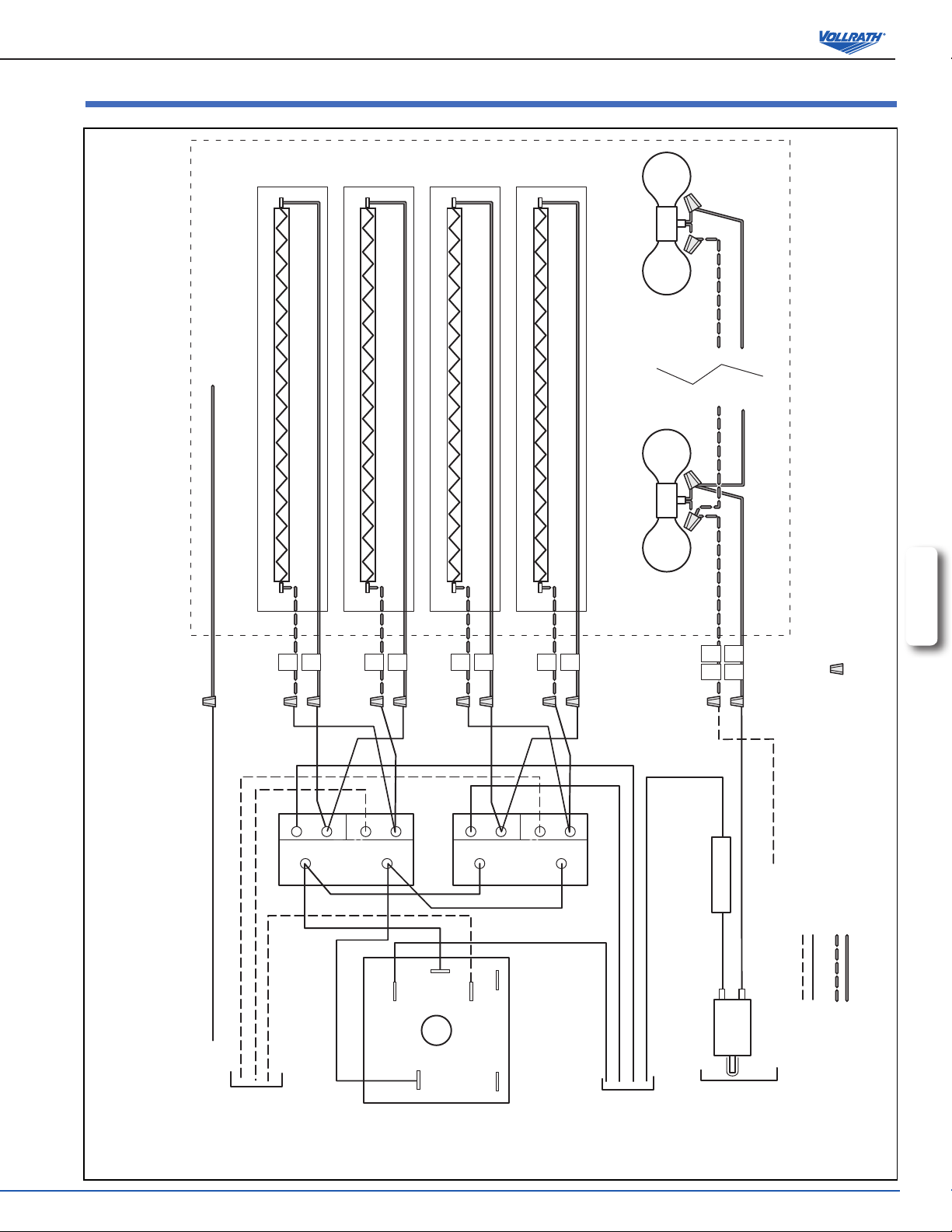
1 1
1 2
1
2
3
4
5
6
7
8
120V
120V
120 Volt Optional Lights
Up to 6 Light Fixtures Wired in Parellel
Heating Element #1
Heating Element #2
Heating Element #3
Heating Element #4
Light
Switch
Use Fuse W/Lighted
units above 16 Amps
L1
Black
Ground Wire
Green
Green
N
White
Optional
Heater AssemblyControl Assembly
Ceramic Wire Nuts
450 °C Temprature Rated Wire
200 °C Temprature Rated Wire
120 Volt Heater W/Toggle Switch Control Assembly Wiring Diagram
electRical diagRam 120 volt heateR ~ switch contRol
ENGLISH
8
OperatOr’s Manual
Optional
208 - 240 Volt Heater W/Infinate Control Assembly Wiring Diagram
electRical diagRam 208 - 240 volt heateR ~ infinite contRol
Ground Wire
Heater AssemblyControl Assembly
Heating Element #1
Heating Element #2
Heating Element #3
120V
120 Volt Optional Lights
Heating Element #4
120V
Up to 6 Light Fixtures Wired in Parellel
Green
ENGLISH
200 °C Temprature Rated Wire
Ceramic Wire Nuts
450 °C Temprature Rated Wire
1
2
3
Relay
Power
L2
4
H2
5
L1
6
7
Relay
Power
8
1 1
1 2
Fuse Use W/Lighted
units above 16 Amps
White Nuetral Wire
Green
L1
Red
H1
P2 P1
L2
Black
Light
Switch
OperatOr’s Manual
9

1 1
1 2
1
2
3
4
5
6
7
8
120V
120V
120 Volt Optional Lights
Up to 6 Light Fixtures Wired in Parellel
Heating Element #1
Heating Element #2
Heating Element #3
Heating Element #4
Light
Switch
Use Fuse W/Lighted
units above 16 Amps
L2
Black
Ground Wire
Green
Green
L1
White
Optional
Heater AssemblyControl Assembly
Ceramic Wire Nuts
450 °C Temprature Rated Wire
200 °C Temprature Rated Wire
208 - 240 Volt Heater W/Toggle Switch Control Assembly Wiring Diagram
electRical diagRam 208 - 240 volt heateR ~ switch contRol
ENGLISH
10
OperatOr’s Manual

notes
ENGLISH
OperatOr’s Manual
11
 Loading...