

Page 1

Operating manual V10.00
11/18
Module-Balancer VAS 6910
Page 2

Content
VAS 6910 hardware operating manual V10.00 11/18 All rights reserved.
I
Content
SAFETY INSTRUCTIONS .......................................................... I
1 GENERAL INFORMATION ........................................... 1-1
1.1 General Notes ............................................................................................. 1-1
1.2 Safety Notes ................................................................................................ 1-2
1.3 Certificate of Calibration .............................................................................. 1-2
1.4 Designated Use ........................................................................................... 1-4
1.5 Associated Documents ................................................................................ 1-4
1.6 Field of application ....................................................................................... 1-4
2 COMPONENTS ............................................................. 2-1
2.1 VAS 6910 Adapter and transport box .......................................................... 2-1
2.2 VAS 6910 Module-Balancer ........................................................................ 2-6
2.3 Cable sets .................................................................................................. 2-12
2.3.1 USB-Cable (USB 2.0 Fischer to USB 2.0 B Rugged)
BV8139, VAS 611003, ASE 611 003 00 000 ................................ 2-12
2.3.2 USB-cable (USB 2.0 A to USB 2.0 B Rugged)
EX7069, VAS 611001 ASE 611 001 00 000 ................................ 2-12
2.3.3 Basic cable set Module adaption 1 (e-up!)
VAS 6910/10 ASE 447 240 00 000 .............................................. 2-13
2.3.4 Extension cable set Module adaption A (e-Golf)
VAS 6910/11 ASE 447 241 00 000 .............................................. 2-14
2.3.5 Basic cable set Module adaption 2 (PHEV)
VAS 6910/12A ASE 447 242 01 000 ........................................... 2-15
2.3.6 Basic cable set Module adaption 3 Adapter cable
Porsche G1 II & E2 II PHEV VAS 6910/13 ASE 447 243 00 000 2-16
2.3.7 Basic cable set Module adaption 4 (XL1)
VAS 6910/14 Purchase via r XL1 After Sales Volkswagen AG .... 2-17
2.3.8 2D-Barcodescanner VAS 6161/1 ASE 447 043 00 000 .............. 2-18
2.4 Scope of delivery ....................................................................................... 2-21
3 COMMISSIONING ......................................................... 3-1
3.1 Firmware-Update ......................................................................................... 3-1
4 OPERATION ................................................................. 4-1
4.1 Preparation .................................................................................................. 4-1
4.1.1 Charging / Discharging .................................................................... 4-1
4.1.2 Safety test ..................................................................................... 4-10
4.1.3 Self-test ......................................................................................... 4-12
4.1.4 Deviceinfo ..................................................................................... 4-14
4.1.5 Viewing all reports ......................................................................... 4-16
Page 3

Content
VAS 6910 hardware operating manual V10.00 11/18 All rights reserved.
II
4.1.6 Result report directory ................................................................... 4-18
4.1.7 Entering a list of operator names .................................................. 4-19
4.1.8 Switch off ...................................................................................... 4-19
5 TROUBLESHOOTING .................................................. 5-1
6 MAINTENANCE AND CARE ........................................ 6-1
6.1 Optical check ................................................................ ............................... 6-1
6.2 Cleaning ...................................................................................................... 6-1
7 TECHNICAL DATA ....................................................... 7-1
7.1 Operating data ............................................................................................. 7-1
8 FAULT REPORT FAX ................................................... 8-1
9 INDEX ............................................................................ 9-1
Products are subject to alterations in form, equipment and design. No claims may be made on the basis
of the information, graphics and descriptions contained in these instructions. Reprints, copies and
translations of this document, in whole or in part, may not be undertaken by third parties without the
express written permission of Volkswagen AG and/or the manufacturer. All rights provided under
copyright law are expressly reserved by Volkswagen AG and the manufacturer. Subject to alteration. All
rights reserved.
VOLKSWAGEN AG Manufacturer: AVL DiTEST GmbH
KD-Werkstattausrüstung Alte Poststrasse 156
D-38436 Wolfsburg 8020 Graz
AUSTRIA
VAS 6910/5
ASE 447 231 00 000 AVL ID-Nr.: AT7784GB Rev. 10
Page 4

Safety instructions
VAS 6910 hardware operating manual V10.00 11/18 All rights reserved.
i
DANGER
Texts with this symbol contain information relating to your safety and how you can
reduce the risk of serious or fatal injuries.
WARNING
Texts with this symbol contain information relating to your safety and how you can
reduce the risk of serious injuries.
CAUTION
Texts with this symbol contain information on how you can avoid damage to the
vehicle and the device.
NOTICE
Text with this symbol contains additional, useful information.
Information
This text indicates important information or instructions. Failure to comply with
these instructions prevents or significantly hampers a successful finalization of the
operations described in this documentation.
Safety Instructions
Explanation of symbols
Symbols with the following meanings are used in the safety instructions of the
operating manuals, unpacking, start-up and brief instructions or other documentation
provided, in screen displays on the tester during operation and on the products
themselves:
Additional danger signal:
Danger due to electrical current.
Remarks:
Page 5

SAFETY INSTRUCTIONS
VAS 6910 hardware operating manual V10.00 11/18 All rights reserved.
ii
WARNING
Read all instructions.
WARNING
Requirements needed to operate this device:
- High-voltage technician (HVT)
- High-voltage expert (HVE)
- Electrically qualified person for high-voltage systems in vehicles
- Electrician for special tasks on high-voltage systems in vehicles.
If you don’t have any of these qualifications please exit this application
immediately!
WARNING
Danger of flashing arcs
Never disconnect wirings while charging or discharging.
Opening the cover stops charging / discharging immediately!
WARNING
Use only as described in this manual.
Use only the referenced accessories from AVL DiTEST! See chap. 2.2 and 2.4.
WARNING
Use the included mains cord set (power cord)!
If the mains cord set has to be changed note the following requirements strictly!
On 240 V mains grid the mains cord set must be designed for a continuous current
of 10 A, on 120V mains grid the mains cord set must be designed for a continuous
current of 20 A.
The mains cord set must have a C19 plug for the connection to the VAS6910
suitable for the above current ratings.
Connect VAS 6910 only to protective contact sockets!
Set up the VAS 6910 in a way that there is always free access to the power
separator!!
(Power cord from the mains socket).
Page 6
SICHERHEITSHINWEISE
VAS 6910 hardware operating manual V10.00 11/18 All rights reserved.
iii
WARNING
Do not operate equipment with a damaged cord or if the equipment has been
dropped or damaged – until it has been examined by a qualified service person.
WARNING
Do not let cord hang over edge of table, bench or counter, or come in contact with
hot manifolds or moving fan blades.
WARNING
An extension cord is not allowed. For testing use only specified cables.
WARNING
To reduce the risk of fire, do not operate equipment in the vicinity of open
containers of flammable liquids (gasoline).
WARNING
Risk of explosions
The VAS 6910 has internal parts which emit sparks and therefore must not be
exposed to flammable fumes. The VAS 6910 should be operated at least 460 mm
(18 inches) above the floor surface since fumes from fuels and other materials
accumulate at floor level.
WARNING
Connecting non-VW HV-Modules
The VAS 6910 has been developed for vehicles from the Volkswagen group.
Connecting the VAS 6910 directly to HV-Modules from other manufacturers can
therefore result in damage to the modules and / or the VAS 6910.
WARNUNG
Set up the VAS 6910 so that adequate ventilation is guaranteed, fans and air vents
are not obstructed and the air must circulate freely!
Page 7

SICHERHEITSHINWEISE
VAS 6910 hardware operating manual V10.00 11/18 All rights reserved.
iv
WARNUNG
When connecting the cell module, make sure the IR temperature sensor is
not covered and ensure direct visibility between the sensor and the module.
CAUTION
The VAS 6910 may only be used within the measurement ranges stipulated in the
technical data and descriptions in the operating manual. Do not perform
measurements on damaged leads.
CAUTION
Cleaning
Before cleaning the VAS 6910, pull out the USB cable and measuring cables!
Clean the VAS 6910 only with a dry cloth. Do not use cleaners or solvents.
READ ALL INSTRUCTIONS - SAVE THESE INSTRUCTIONS!
Page 8

SAFETY INSTRUCTIONS
VAS 6910 hardware operating manual V10.00 11/18 All rights reserved.
v
IMPORTANT SAFETY INSTRUCTIONS
1. Read all instructions.
2. Care must be taken as burns can occur from touching hot parts.
3. Do not operate equipment with a damaged cord or if the equipment
has been dropped or damaged - until it has been examined by a
qualified serviceman.
4. Do not let cord hang over edge of table, bench or counter or come in
contact with hot manifolds or moving fan blades.
5. If an extension cord is necessary, a cord with a current rating equal
to or more than that of the equipment should be used. Cords rated
for less current than the equipment may overheat. Care should be
taken to arrange the cord so that it will not be tripped over or pulled.
6. Always unplug equipment from electrical outlet when not in use.
Never use the cord to pull the plug from the outlet. Grasp plug and
pull to disconnect.
7. Let equipment cool completely before putting away. Loop cord
loosely around equipment when storing.
8. To reduce the risk of fire, do not operate equipment in the vicinity of
open containers of flammable liquids (gasoline).
9. Adequate ventilation should be provided when working on operating
internal combustion engines.
10. Keep hair, loose clothing, fingers, and all parts of body away from
moving parts.
11. To reduce the risk of electric shock, do not use on wet surfaces or
expose to rain.
12. Use only as described in the manual. Use only manufacturer´s
recommended attachments.
13. ALWAYS WEAR SAFETY GLASSES. Everyday eyeglasses only
have impact resistant lenses, they are NOT safety glasses.
SAVE THESE INSTRUCTIONS
Page 9

General Information
VAS 6910 hardware operating manual V10.00 11/18 All rights reserved.
1-1
1 General Information
1.1 General Notes
The Module Balancer VAS 6910, here after named VAS6910, is able to charge and
discharge single cell modules of high voltage batteries from E-cars and hybrid cars.
To guarantee an overall equal load of all cell modules on a HV-battery, the new cell
module has to be charged / discharged to meet this load of the whole battery.
The conditioned „balanced“ cell module replaces the defect cell module.
The VAS6910 is designed to use in car shops which have to do HV battery repairs.
To use this device you must have a special qualification. See below.
Please follow the regulation valid to your country!
Read this operating manual and follow especially the safety hints!
Page 10

General Information
VAS 6910 hardware operating manual V10.00 11/18 All rights reserved.
1-2
1.2 Safety Notes
Please observe the safety instructions for the VAS 6910.
You can find them after the contents section.
1.3 Certificate of Calibration
The manufacturer hereby declares (fig 1-1) that the device delivered with this
operating manual does not require any calibration within the first 2 years after its
delivery. Subsequent calibrations should be carried out every 12 months.
Page 11

General Information
VAS 6910 hardware operating manual V10.00 11/18 All rights reserved.
1-3
Modul-Balancer VAS 6910
Bestellnummer: VS9042
Das Modul-Balancer VAS 6910 wurde unter Einhaltung aller Vorgaben nach
der jeweils gültigen Prüfvorschrift erfolgreich getestet und hat in
einwandfreiem Zustand unser Haus verlassen.
In den ersten 24 Monaten nach der Auslieferung des Geräts ist keine
Kalibrierung erforderlich.
The module balancer VAS 6910 was tested successfully with compliance
to all specified values and under the actual test procedure and left our
facilities in perfect condition.
During the first 24 month after delivery of the device, calibration is not
required.
AVL DiTEST ist nach ISO 9001 zertifiziert!
AVL DiTEST is accredited according to ISO 9001!
AVL DiTEST GmbH - Alte Poststrasse 156 - 8020 Graz - AUSTRIA
Fig. 1-1 Certificate of initial calibration
Page 12

General Information
VAS 6910 hardware operating manual V10.00 11/18 All rights reserved.
1-4
WARNUNG
The Housing should only be opened by service personal. See Service information,
Chap. 3.1. Regional Service partners).
1.4 Designated Use
It’s only allowed to use the VAS 6910 in that way, described in this manual.
The product described has been developed, manufactured and checked according to
the relevant safety standards. If the safety instructions are observed, the start-up is
carried out as stipulated, the device is used for the intended purpose and the
recommended maintenance and care is also observed, then in normal cases there is
no danger regarding damages to property or for the health of persons associated
with the VAS 6910.
1.5 Associated Documents
Along with this operating manual, which is to be used by the user in the workshop,
there are also the following technical documents for the VAS 6910:
Unpacking instructions, start-up, brief instructions VAS 6910
Registration certificate
Service information
1.6 Field of application
The VAS6910 is designed for charging / discharging of single cell modules of a HV
battery to a certain load level.
Page 13

Components
VAS 6910 hardware operating manual V10.00 11/18 All rights reserved.
2-1
1
2 Components
2.1 VAS 6910 Adapter and transport box
Adapter and transport box (top view)
Fig. 2-1 Adapter and transport box (top view)
(1) Window
Page 14

Components
VAS 6910 hardware operating manual V10.00 11/18 All rights reserved.
2-2
1
1
2
3
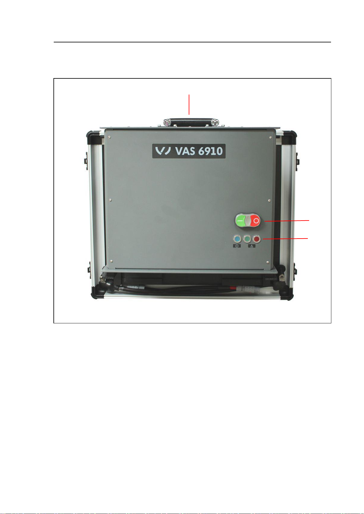
Adapter and transport box (front view)
Fig. 2-2 Adapter and transport box (front view)
(1) Carrying handle
Adapter- and transportation box (side view left/right)
Fig. 2-3 Adapter and transport box, closed (side view)
(1) Carrying handle
(2) Latch
(3) Latch
Page 15
Components
VAS 6910 hardware operating manual V10.00 11/18 All rights reserved.
2-3
1
2
3
Adapter and transport box open with Module-Balancer (top-view)
Fig. 2-4 Adapter und transport box open (top view).
(1) Carrying handle
(2) Module-Balancer
(3) Adapter- and transportation box, (bottom part)
Page 16

Components
VAS 6910 hardware operating manual V10.00 11/18 All rights reserved.
2-4
1
2
Adapter and transport box open, Module-Balancer mounted, no cell module
(side view)
Fig. 2-5 Adapter and transportation box open, side view
(1) Module-Balancer
(2) Adapter- and transportation box, bottom part
Page 17
Components
VAS 6910 hardware operating manual V10.00 11/18 All rights reserved.
2-5
1
2
3
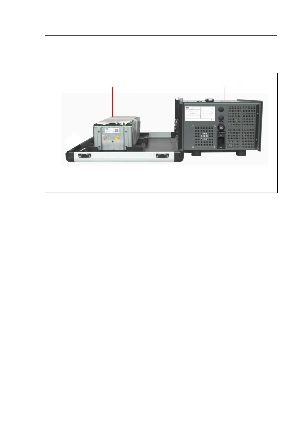
Adapter und transport box open, Module-Balancer attached and cell module
inserted, side view.
Fig. 2-6 Adapter and transport box open with cell module inserted, side view
(1) Cell module
(2) Module-Balancer
(3) Adapter and transport box (bottom part)
Page 18

Components
VAS 6910 hardware operating manual V10.00 11/18 All rights reserved.
2-6
1
2.2 VAS 6910 Module-Balancer
VAS 6910 Module-Balancer, rear view
Fig. 2-7 VAS 6910 Module-Balancer, rear view
(1) Carrying handle
Page 19

Components
VAS 6910 hardware operating manual V10.00 11/18 All rights reserved.
2-7
WARNING
Set up the VAS 6910 so that adequate ventilation is guaranteed, fans and air
vents are not obstructed and the air must circulate freely!
1
2
3
4
VAS 6910 Module-Balancer, side view right
Fig. 2-8 Electronic box, side view right
(1) Specification plate
(2) USB-connector (rugged) for connection of the USB cable
(3) Air inlet grill
(6) Power supply inlet. Connection for power cord
Page 20

Components
VAS 6910 hardware operating manual V10.00 11/18 All rights reserved.
2-8
WARNING
Use the included mains cord set (power cord)!
If the mains cord set has to be changed note the following requirements strictly!
On 240 V mains grid the mains cord set must be designed for a continuous
current of 10 A, on 120V mains grid the mains cord set must be designed for a
continuous current of 20 A.
The mains cord set must have a C19 plug for the connection to the VAS6910
suitable for the above current ratings.
Connect VAS 6910 only to protective contact sockets!
Set up the VAS 6910 in a way that there is always free access to the power
separator!!
(Power cord from the mains socket).
Page 21
Components
VAS 6910 hardware operating manual V10.00 11/18 All rights reserved.
2-9
WARNING
Set up the VAS 6910 so that adequate ventilation is guaranteed, fans and air
vents are not obstructed and the air must circulate freely!
1
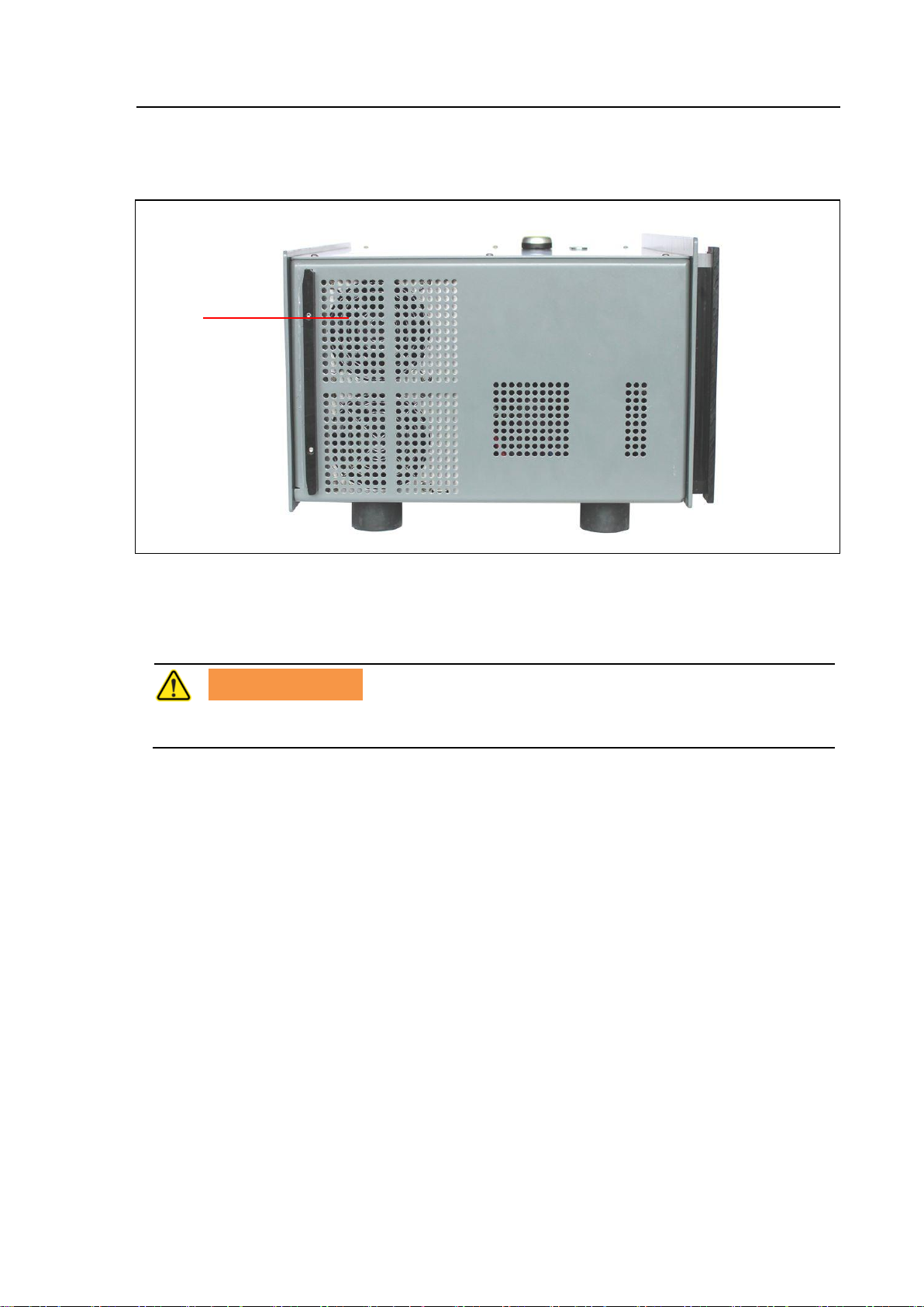
VAS 6910 Module-Balancer, side view left
Fig. 2-9 VAS 6910 Module-Balancer, side view left
(1) Air inlet grill
Page 22
Components
VAS 6910 hardware operating manual V10.00 11/18 All rights reserved.
2-10
1
4
3
2
5 6 7
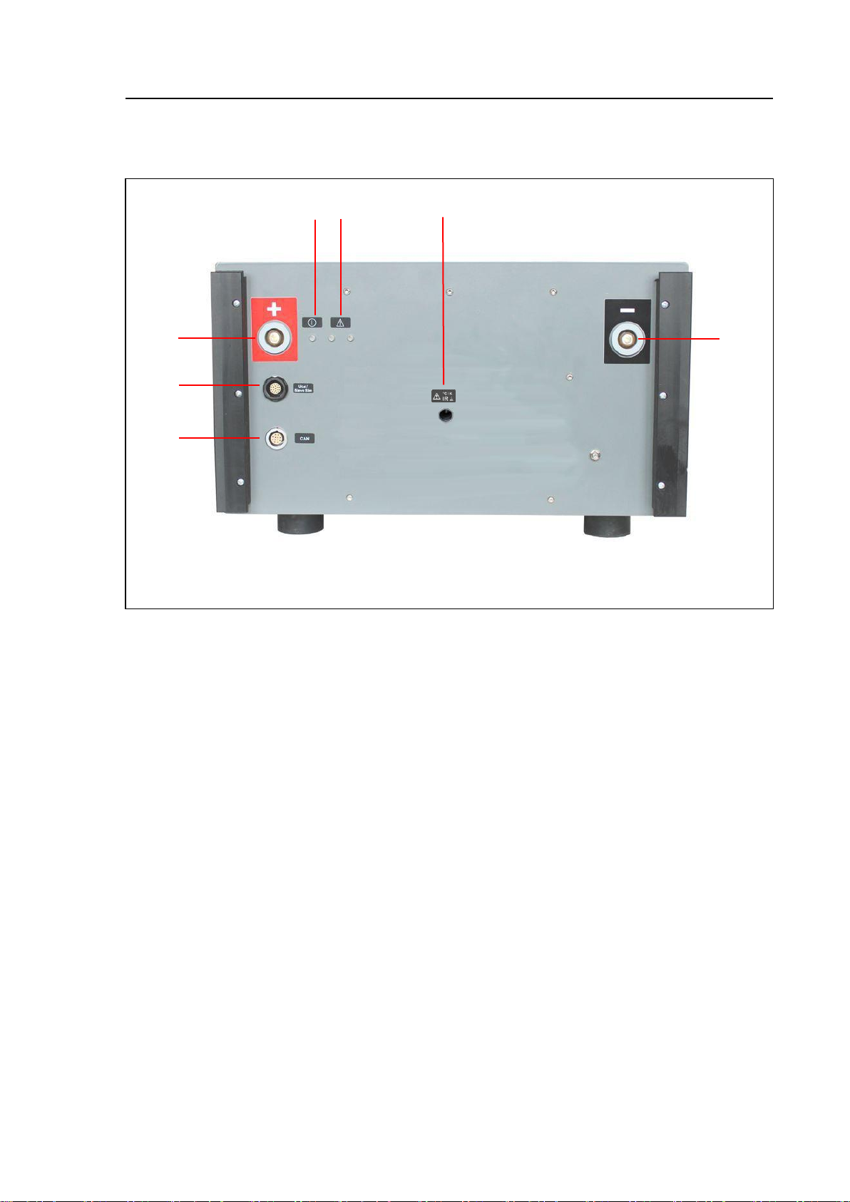
VAS 6910 Module-Balancer, front view
Fig. 2-10 VAS 6910 Module-Balancer, front view
(1) Connector „Minus“ (black)
(2) Connector „CAN“
(3) Connector „U Slave/Sim“
(4) Connector „Plus“ (red)
(5) LED blue Device on and ready
blue flashing Device is idle
(6) LED red Charging / discharging is running
green No charging / discharging active
(7) IR temperature sensor
Page 23
Components
VAS 6910 hardware operating manual V10.00 11/18 All rights reserved.
2-11
2
1
3
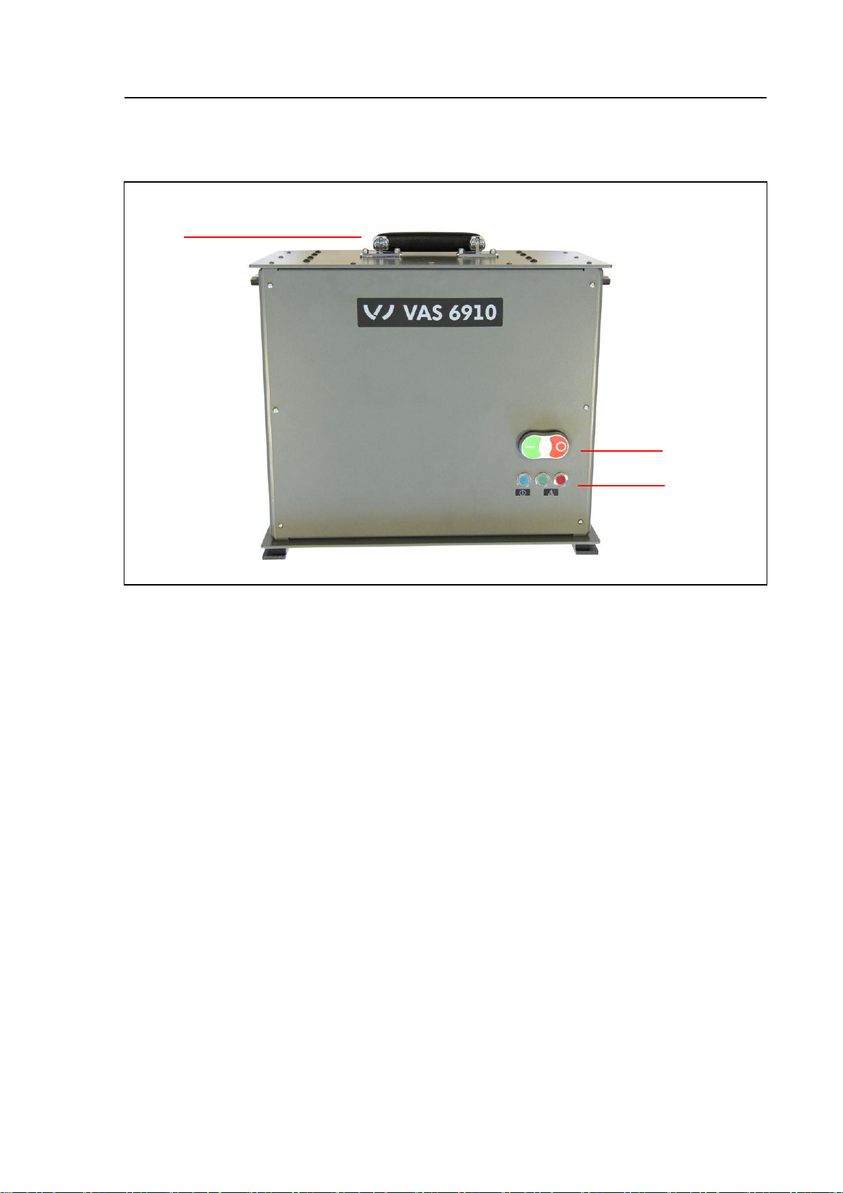
VAS 6910 Module-Balancer, top view
Fig. 2-11 Module-Balancer, top view
(1) Carrying handle
(2) On / Off button
green Power module ON (active mode)
red Power module OFF (idle mode)
(3) LEDs
blue Device is on and ready
blue blinking Stand-by / idle mode
green No Charging / discharging is running
red Charging / discharging is active or an error has
happened.
Page 24
Components
VAS 6910 hardware operating manual V10.00 11/18 All rights reserved.
2-12
2.3 Cable sets
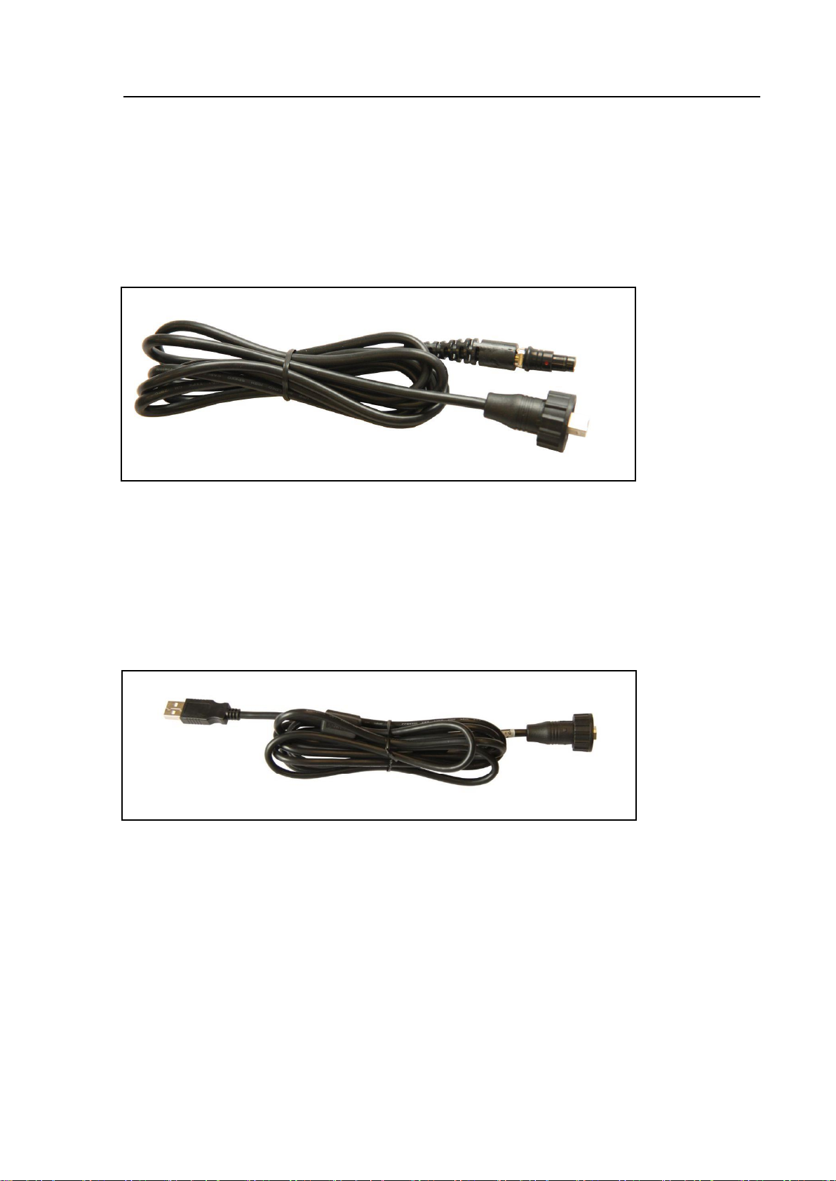
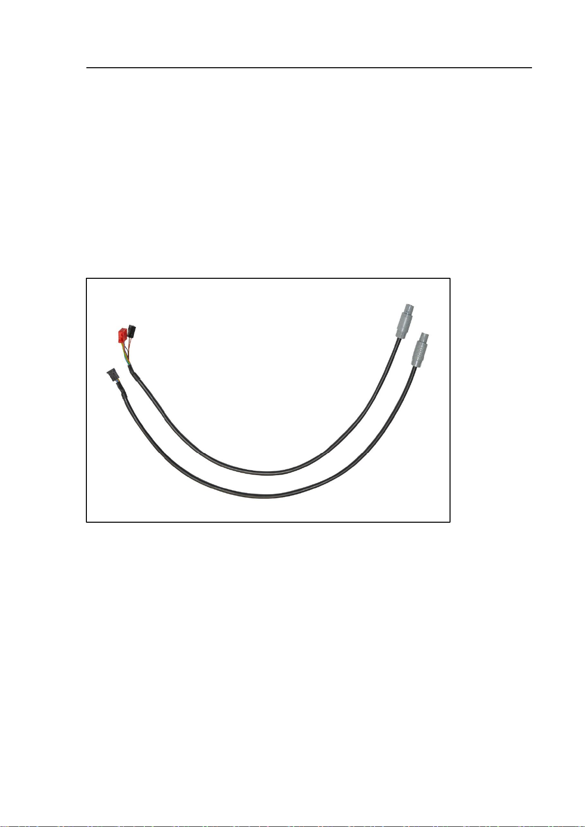
2.3.1 USB-Cable (USB 2.0 Fischer to USB 2.0 B Rugged) BV8139, VAS 611003, ASE 611 003 00 000
This USB cable connects the Module Balancer VAS 6910 to the VW Diagnostic
system. Free Fischer connector is needed.
Fig 2-12 USB-cable USB 2.0 Fischer to USB 2.0 B Rugged
2.3.2 USB-cable (USB 2.0 A to USB 2.0 B Rugged) EX7069, VAS 611001 ASE 611 001 00 000
This cable is used if no Fischer connector is available at the VW Diagnostic system.
Fig 2-13 USB-Cable USB 2.0 A to USB 2.0 B Rugged
Page 25
Components
VAS 6910 hardware operating manual V10.00 11/18 All rights reserved.
2-13
(1)
(2)
(3)
(4)
(5)
(6)
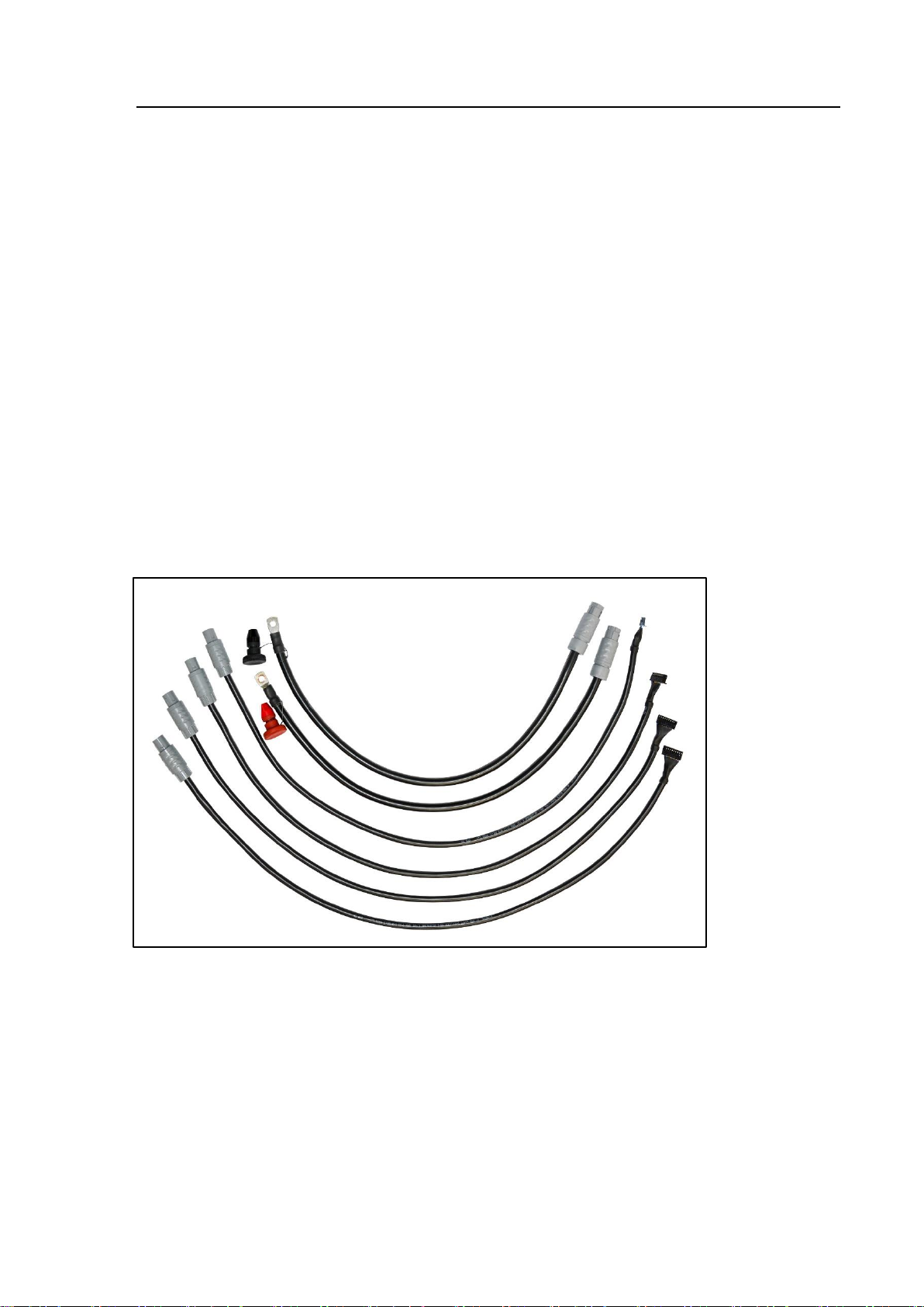
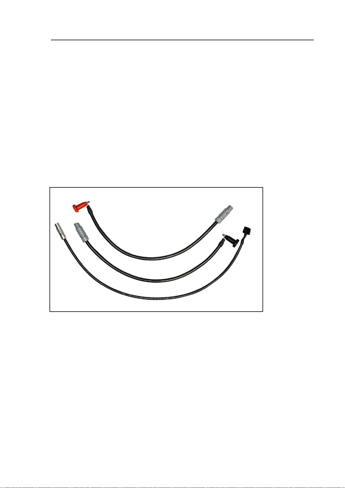
2.3.3 Basic cable set Module adaption 1 (e-up!) VAS 6910/10 ASE 447 240 00 000 BO7852
This cable set consists of 6 cables:
1. VAS 6910/10-1 ASE 447 246 00 000 BV8190
Cable for „Plus“-Pol
2. VAS 6910/10-2 ASE 447 247 00 000 BV8191
Cable for „Minus“-Pol
3. VAS 6910/10-3 ASE 447 248 00 000 BV8140
Analog-Meas. lead for module variant 12E.915.591
4. VAS 6910/10-4 ASE 447 249 00 000 BV8141
Analog-Meas. lead for module variant 12E.915.592
5. VAS 6910/10-5 ASE 447 250 00 000 BV8142
Analog-Meas. lead for module variant 12E.915.591.A
6. VAS 6910/10-6 ASE 447 251 00 000 BV8143
Analog-Meas. lead for module variant 12E.915.592.A
Usage is on e-UP! 2014
Fig 2-14 Basic cable set Module adaption 1 (e-up!)
Page 26
Components
VAS 6910 hardware operating manual V10.00 11/18 All rights reserved.
2-14
(1)
(2)
2.3.4 Extension cable set Module adaption A (e-Golf) VAS 6910/11 ASE 447 241 00 000 BO7853
Set consists of:
1. VAS 6910/11-1 ASE 447 257 00 000 BV8145
Slave Simulation cable for Master-Modules
2. VAS 6910/11-2 ASE 447 258 00 000 BV8146
Analogue meas. cable for Slave-Modules
For Volkswagen e-Golf cable sets VAS6910/11 (this one) and the VAS6910/12A are
necessary!
Start of usage is at e-Golf production year 2014 ff.
Fig 2-15 Kabelsatz e-Golf
Page 27
Components
VAS 6910 hardware operating manual V10.00 11/18 All rights reserved.
2-15
(1)
(2)
(3)
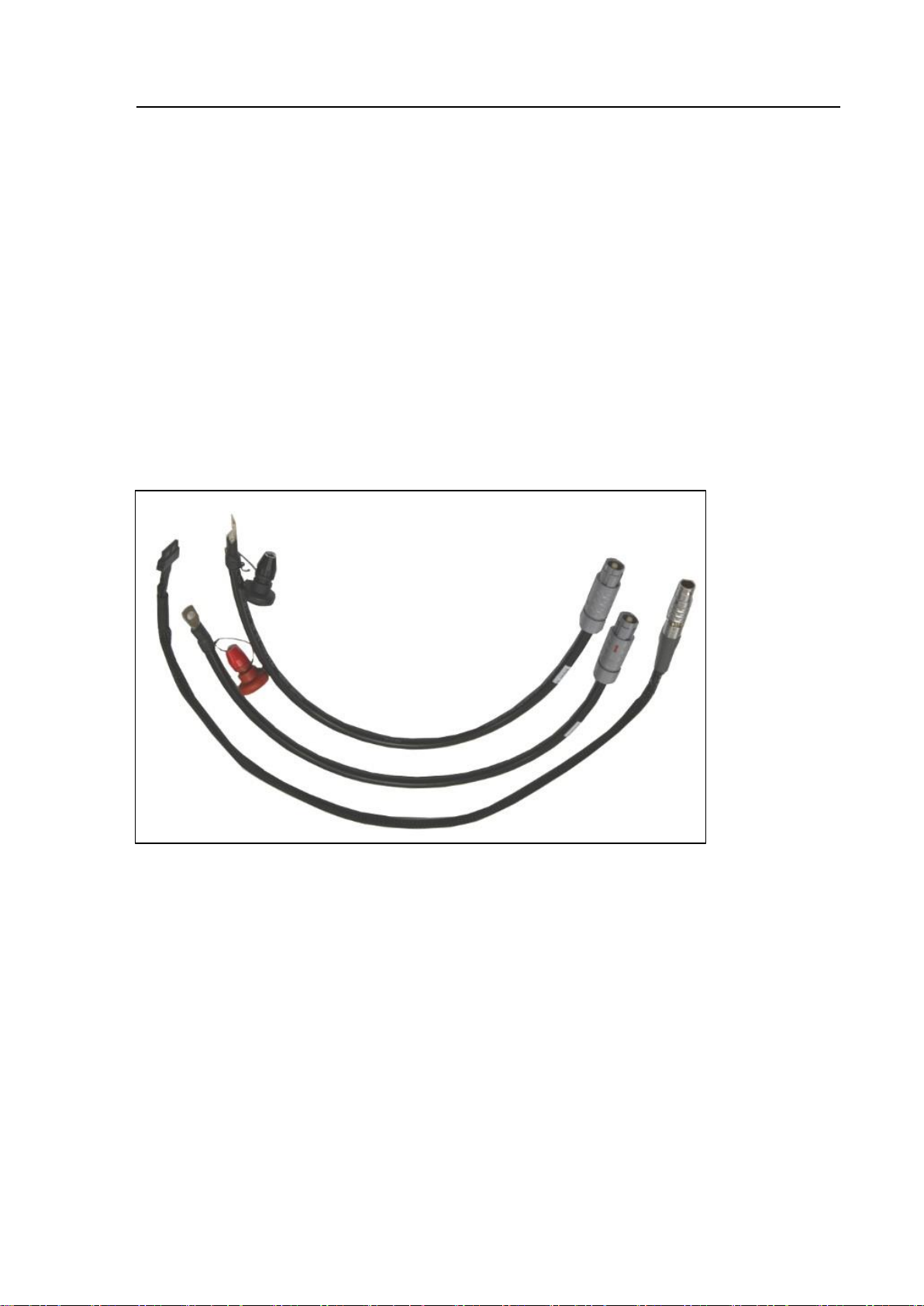
2.3.5 Basic cable set Module adaption 2 (PHEV) VAS 6910/12A ASE 447 242 01 000 BO7854
The Basic Cable Set Module adaption (PHEV) consists of three cables:
1. VAS 6910/12A-1 ASE 447 252 00 000 BV8188
Cable for “plus” with loose cable clips for use with PHEV modules, AUDI A3
e-tron, e-Golf and Golf GTE.
2. VAS 6910/12A-2 ASE 447 253 00 000 BV8189
Cable for „minus“ with loose cable clips for use with PHEV modules, AUDI A3
e-tron, e-Golf and Golf GTE.
3. VAS 6910/12A-3 ASE 447 254 00 000 BV8265
CAN cable for connecting to the module controller
Start of usage is on E-Golf and PHEV from manufacture year 2014 ff.
Fig: 2-16 Basic cable set Module adaption 3 (PHEV)
Page 28
Components
VAS 6910 hardware operating manual V10.00 11/18 All rights reserved.
2-16
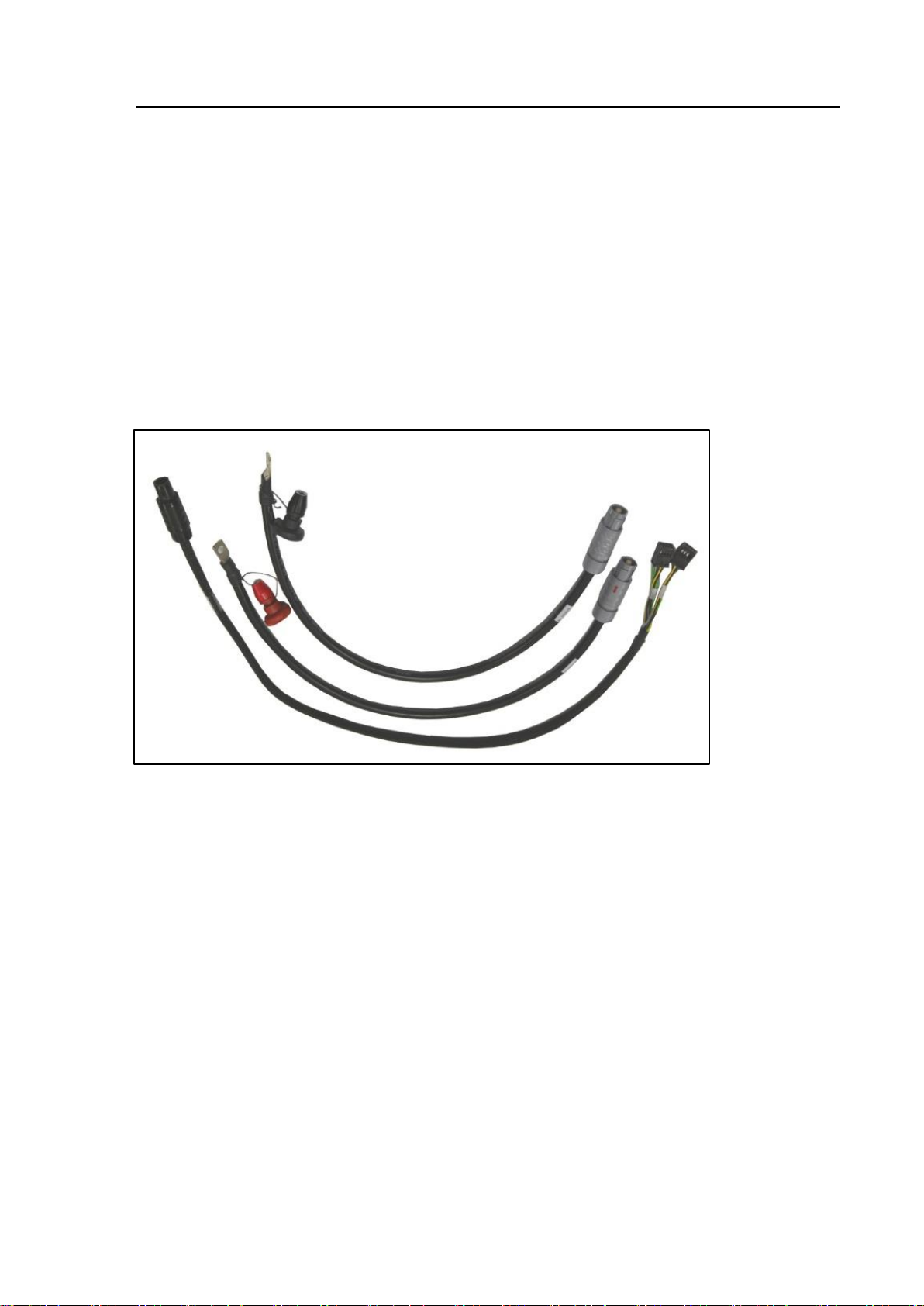
2.3.6 Basic cable set Module adaption 3 Adapter cable Porsche G1 II & E2 II PHEV VAS 6910/13 ASE 447 243 00 000 BO7855
The Basic Cable Set Module adaption 3 consists of three cables:
1. Cable for „plus“
Loose cable clip and M6 knurled nut BV8190
2. Cable for „minus“
Loose cable clip and M6 knurled nut BV8191
3. CAN cable for module BV8200
- Porsche G1 II PHEV 24 Ah
- Porsche E2 II PHEV 28 Ah
Start of usage is on Porsche Cayenne and Panamera Hybrid.
Fig 2-17 Adapter cable Porsche G1 II & E2 II PHEV
Page 29
Components
VAS 6910 hardware operating manual V10.00 11/18 All rights reserved.
2-17
2.3.7 Basic cable set Module adaption 4 (XL1) VAS 6910/14 BO7865 Purchase via r XL1 After Sales Volkswagen AG
The Basic Cable Set XL 1 consists of three cables:
1. Cable for „plus“
Loose cable clip and M6 knurled nut BV8190
2. Cable for „minus“
Loose cable clip and M6 knurled nut BV8191
3. Analogue cable for XL 1 BV8193
Start of usage is on VW XL 1.
Fig 2-18 Basic Cable Set XL 1
Page 30
Components
VAS 6910 hardware operating manual V10.00 11/18 All rights reserved.
2-18
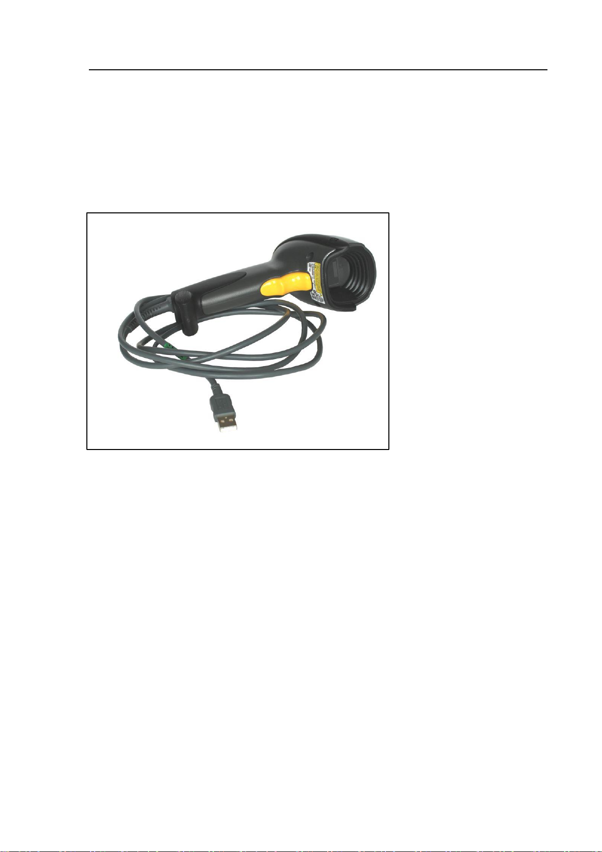
2.3.8 2D-Barcodescanner VAS 6161/1 ASE 447 043 00 000
The scanner is used to scan the bar code attached to the cell modules. The canner
has an USB-Type A connector and has to be connected to the VW Diagnostic system
(VAS 6150A / VAS 6051B / VAS 6160).
Fig. 2-19 2D-Barcodescanner
Page 31
Components
VAS 6910 hardware operating manual V10.00 11/18 All rights reserved.
2-19
(1)
(2)
(1)
(2)
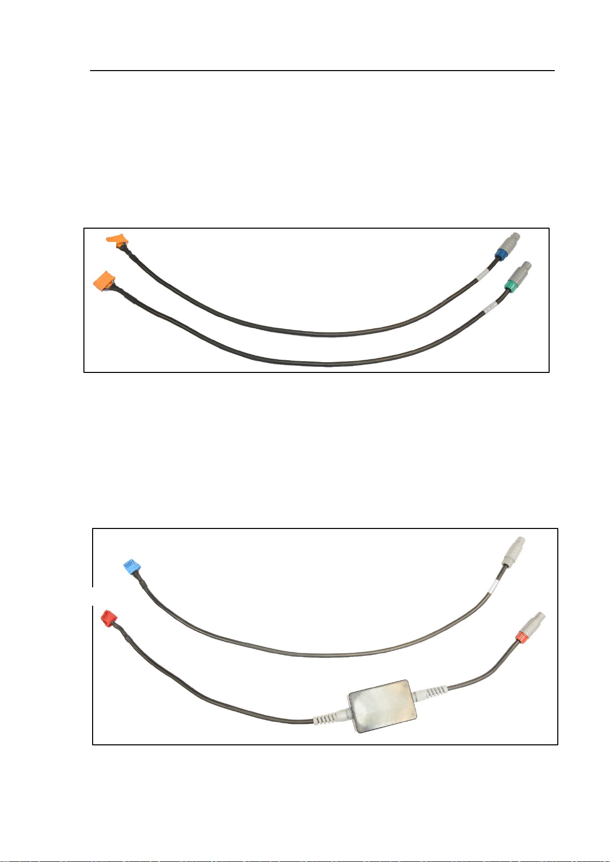
2.3.9 Basic cable VAS 6910/15
1. VAS 6910/15-1 ASE 447 255 00 000 BV8294
e - Up R Analog connection cable for module variant 12E.915.592.B/…..592.C
2. VAS 6910/15-2 ASE 447 256 00 000 BV8295
e - Up L Analog Analog connection cable for module variant
12E.915.591.E/….591.F
Fig 2-20 Basic Cable
2.3.10 Basic cable VAS 6910/16
1. VAS 6910/16-1 ASE 447 245 00 000 BV8296
CCE Analog connection cable for slave modules
2. VAS 6910/16-2 ASE 447 259 00 000 BV8315
CMC-CCE slave simulation e-Golf 300 GP
Fig 2-21 Basic Cable
Page 32
Components
VAS 6910 hardware operating manual V10.00 11/18 All rights reserved.
2-20
(1)
(2)
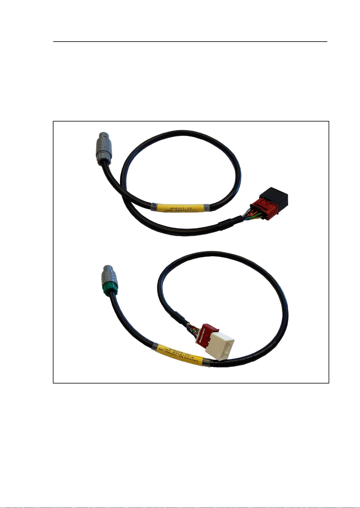
2.3.11 Basic cable VAS 6910/17
1. VAS 6910/17-1 ASE 447 260 00 000 BV8317
For connection to Audi e-tron (C-BEV), module 4KE.915.591.D, 3S4P „normal“
2. VAS 6910/17-2 ASE 447 261 00 000 BV8318
For connection to Audi e-tron (C-BEV), module 4KE.915.591.E, 3S4P „mirrored“
Fig 2-2 Basic cable VAS 6910/17
Page 33

Components
VAS 6910 hardware operating manual V10.00 11/18 All rights reserved.
2-21
Components
System-
delivery
Accessories
VAS 6910
VAG-No.: ASE 447 230 00 000
AVL-No.:
Module-Balancer VAS 6910
incl. power cord
incl. Unpacking und Start Up Manual (printed copy)
●
VAS 6910/1
VAG-No.: ASE 447 231 00 000
AVL-No.: BG7455
Adapter- und Transport box
●
VAS 6910/2
VAG-No.: ASE 447 232 00 000
AVL-No.: BO7841
Module-Balancer incl. power cord
●
VAS 611003
VAG-No.: ASE 611 003 00 000
AVL-No.: BV8139
USB-cable
(USB 2.0 Fischer to USB 2.0 B Rugged)
●
VAS 611001
VAG-No.: ASE 611001 00 000
AVL-No.: EX7069
USB-cable
(USB 2.0 A to USB 2.0 B Rugged)
●
VAS 6910/5
VAG-No.: ASE 447 235 00 000
AVL-No.: BO7859
Operating manuals and software on CD
●
2.4 Scope of delivery
Table 2-1 scope of delivery
Page 34

Components
VAS 6910 hardware operating manual V10.00 11/18 All rights reserved.
2-22
Components
Systemdelivery
Accessories
VAS 6910/10
VAG-N0.: ASE 447 240 00 000
AVL-No: BO7852
Basic cable set module adaption 1:
e-up (VW120/7)
1. VAS 6910/10-1 ASE 447 246 00 000
BV8190
Cable for „Plus“-Pol
2. VAS 6910/10-2 ASE 447 247 00 000
BV8191
Cable for „Minus“-Pol
3. VAS 6910/10-3 ASE 447 248 00 000
BV8140
Analog-Meas. lead for module variant
12E.915.591
4. VAS 6910/10-4 ASE 447 249 00 000
BV8141
Analog-Meas. lead for module variant
12E.915.592
5. VAS 6910/10-5 ASE 447 250 00 000
BV8142
Analog-Meas. lead for module variant
12E.915.591.A
6. VAS 6910/10-6 ASE 447 251 00 000
BV8143
Analog-Meas. lead for module variant
12E.915.592.A
●
VAS 6910/11
VAG-Nr.: ASE 447 241 00 000
AVL-Nr.: BO7853
Extension cable set module adaption A:
E-Golf (VW370/7)
Set consists of
1. VAS 6910/11-1 ASE 447 257 00 000
BV8145
Slave Simulation cable for Master-Modules
2. VAS 6910/11-2 ASE 447 258 00 000
BV8146
Analogue meas. cable for Slave-Modules
For VOLKSWAGEN E-Golf both cable
VAS 6919/11 and VAS 6910/12A are necessary!
●
Page 35

Components
VAS 6910 hardware operating manual V10.00 11/18 All rights reserved.
2-23
VAS 6910/12A
VAG-Nr.: ASE 447 242 01 000
AVL-Nr.: BO7854
Basic cable set module adaption 2 (PHEV):
1. VAS 6910/12A-1 ASE 447 252 00 000
BV8188
Cable for “plus” with loose cable clips for
use with PHEV modules, AUDI A3
e-tron, e-Golf and Golf GTE.
2. VAS 6910/12A-2 ASE 447 253 00 000
BV8189
Cable for „minus“ with loose cable clips for
use with PHEV modules, AUDI A3 e-tron,
e-Golf and Golf GTE.
3. VAS 6910/12A-3 ASE 447 254 00 000
BV8265
For: e-Golf, Group module (PHEV)
CAN cable for connecting to the module
controller
For PHEV module and for AUDI A3-e-tron
●
VAS 6161/1
VAG-Nr.: ASE 447 043 00 000
AVL-Nr.:
2D-bar code reader with USB cable.
Distribution Volkswagen AG only!
●
Page 36

Components
VAS 6910 hardware operating manual V10.00 11/18 All rights reserved.
2-24
Components
System-
delivery
Accessories
VAS 6910/13
VAG-Nr.: ASE 447 243 00 000
AVL-Nr.: BO7855
Basic cable set module adaption 3
Adapter cable Porsche G1 II & E2 II PHEV
1. cable for „plus“
loose cable clip and M6 knurled nut BV8190
2. cable for „minus“
loose cable clip and M6 knurled nut BV8191
3. CAN cable BV8200
●
VAS 6910/14
Purchase via r XL1 After Sales Volkswagen AG
AVL-Nr.: BO7865
Basic cable set module adaption 4
Adapter cable XL 1
1. cable for „plus“
loose cable clip and M6 knurled nut BV8190
2. cable for „minus“
loose cable clip and M6 knurled nut BV8191
3. Analogue cable for module XL 1 BV8193
●
Basic Cable VAS 6910/15:
1. VAS 6910/15-1 ASE 447 255 00 000
BBV8294
e - Up R Analog connection cable for
module variant 12E.915.592.B/…..592.C
2. VAS 6910/15-2 ASE 447 256 00 000
BV8295
e - Up L Analog Analog connection cable for
module variant 12E.915.591.E/….591.F
●
Basic Cable VAS 6910/16
1. VAS 6910/16-1 ASE 447 245 00 000
BV8296
CCE Analog connection cable for slave
modules
2. VAS 6910/16-2 ASE 447 259 00 000
BV8315
CMC-CCE slave simulation e-Golf 300 GP
●
Page 37
Components
VAS 6910 hardware operating manual V10.00 11/18 All rights reserved.
2-25
Basic Cable VAS 6910/17
1. VAS 6910/17-1 ASE 447 260 00 000
BV8317
For connection to Audi e-tron (C-BEV),
module 4KE.915.591.D, 3S4P „normal“
2. VAS 6910/17-2 ASE 447 261 00 000 BV8318
For connection to Audi e-tron (C-BEV), module
4KE.915.591.E, 3S4P „mirrored“
●
WARNING
Use only the referenced accessories from AVL DiTEST!
WARNING
Use the included mains cord set (power cord)!
If the mains cord set has to be changed note the following requirements strictly!
On 240 V mains grid the mains cord set must be designed for a continuous current
of 10 A, on 120 V mains grid the mains cord set must be designed for a
continuous current of 20 A.
The mains cord set must have a C19 plug for the connection to the VAS 6910
suitable for the above current ratings.
Connect VAS 6910 only to protective contact sockets!
Set up the VAS 6910 in a way that there is always free access to the power
separator!!
(Power cord from the mains socket).
Page 38
Commissioning
VAS 6910 hardware operating manual V10.00 11/18 All rights reserved.
3-1
3 Commissioning
Use the “Unpacking- Start-up and brief instructions” manual for the VAS6910.
3.1 Firmware-Update
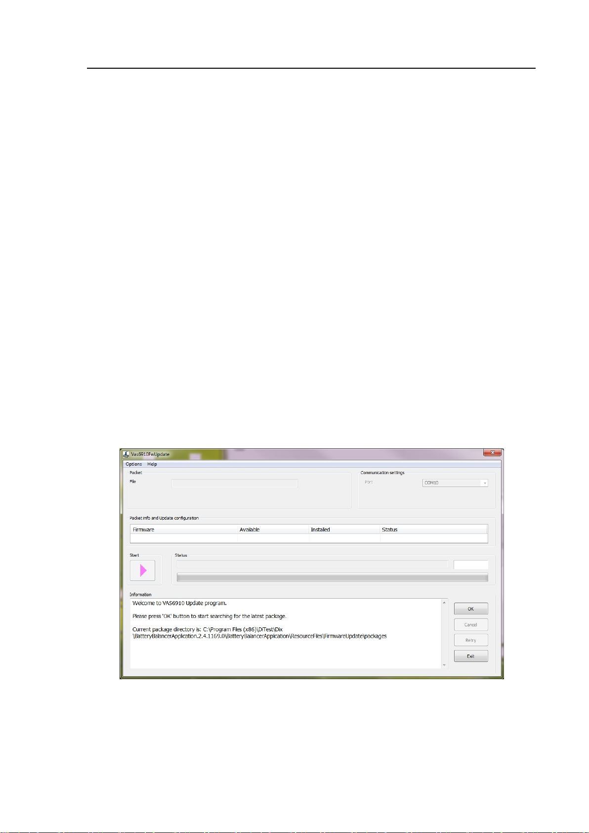
To do an update of the VAS 6910 firmware proceed as follows:
1. Start the update program by click on
Start│All programs│DiTEST│VAS6910│VAS 6910 Firmware
Update.
2. Click the OK Button twice.
The newest program version and the actual installed version are shown.
If a newer version is available please start the update process by clicking on the
then enabled Start button.
3. Follow the instructions on the screen.
Fig. 3-1 Firmware Update
Page 39
Operation
VAS 6910 hardware operating manual V10.00 11/18 All rights reserved.
4-1
1
4 Operation
4.1 Preparation
Prepare the VAS 6910 for operation. ( chapter. 3 „Commissioning“).
4.1.1 Charging / Discharging
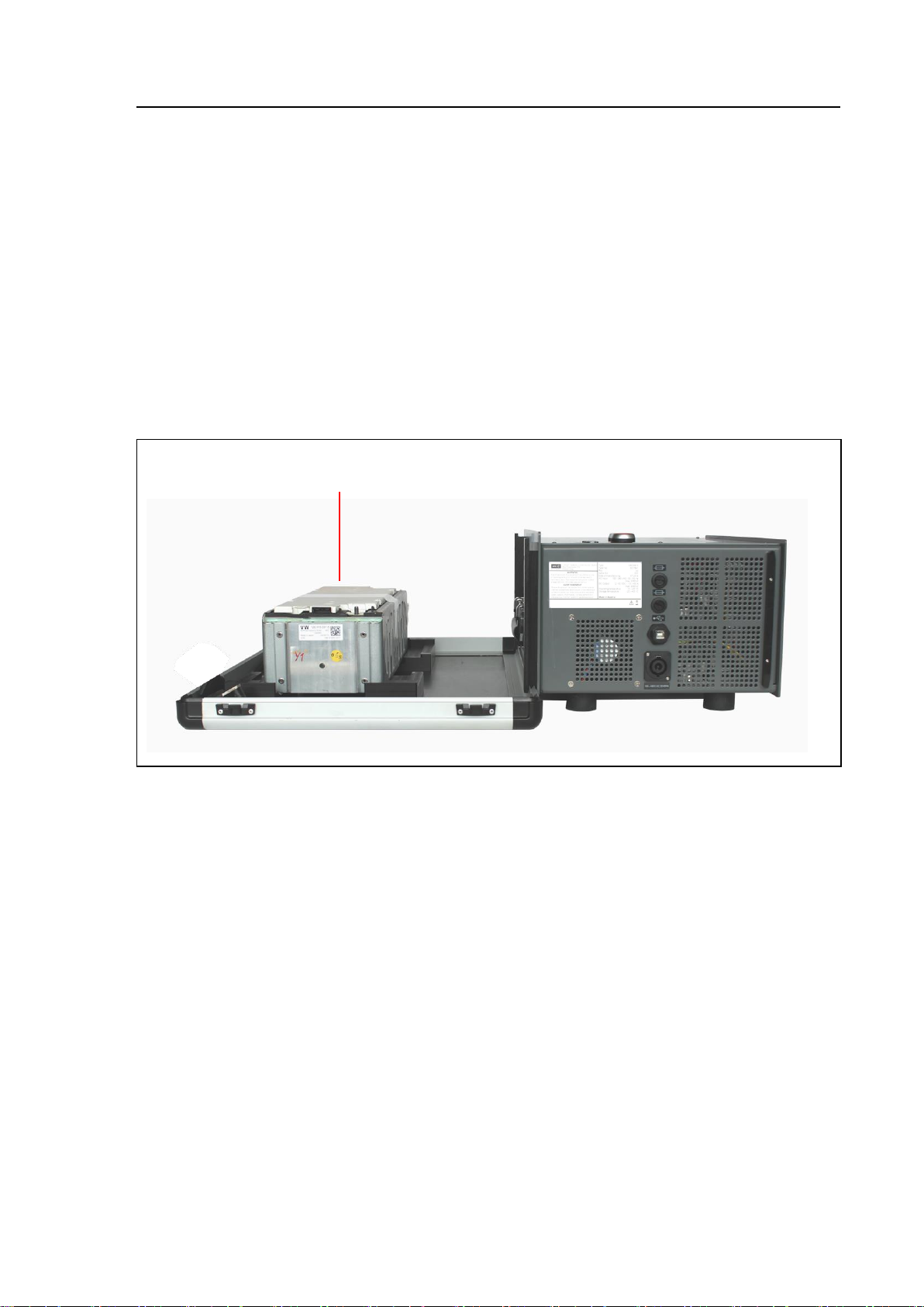
1. Put the cell module (1) to charged/discharged into the adaption box of the
VAS6910.
Fig. 4-1 Cell module inserted
Page 40
Operation
VAS 6910 hardware operating manual V10.00 11/18 All rights reserved.
4-2
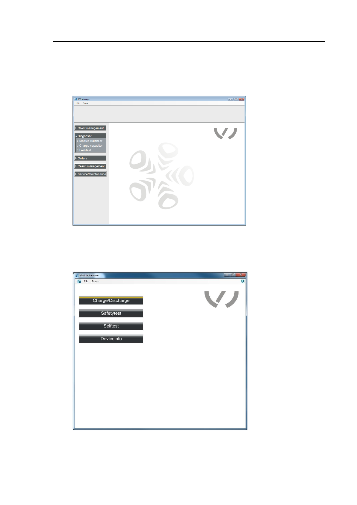
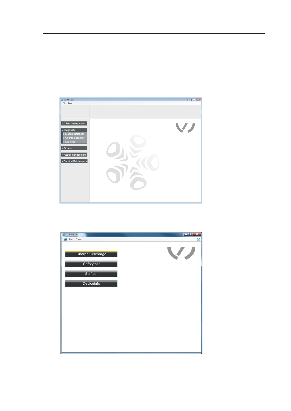
2. Start the VAS Manager by selecting: Start│Programs│
DiTEST│VAS DSS.
3. Select Diagnose│Module Balancer.
Fig. 4-2 DSS Manager
4. The start screen appears:
Select Charge/Discharge.
Fig. 4-3 Start screen
Page 41
Operation
VAS 6910 hardware operating manual V10.00 11/18 All rights reserved.
4-3
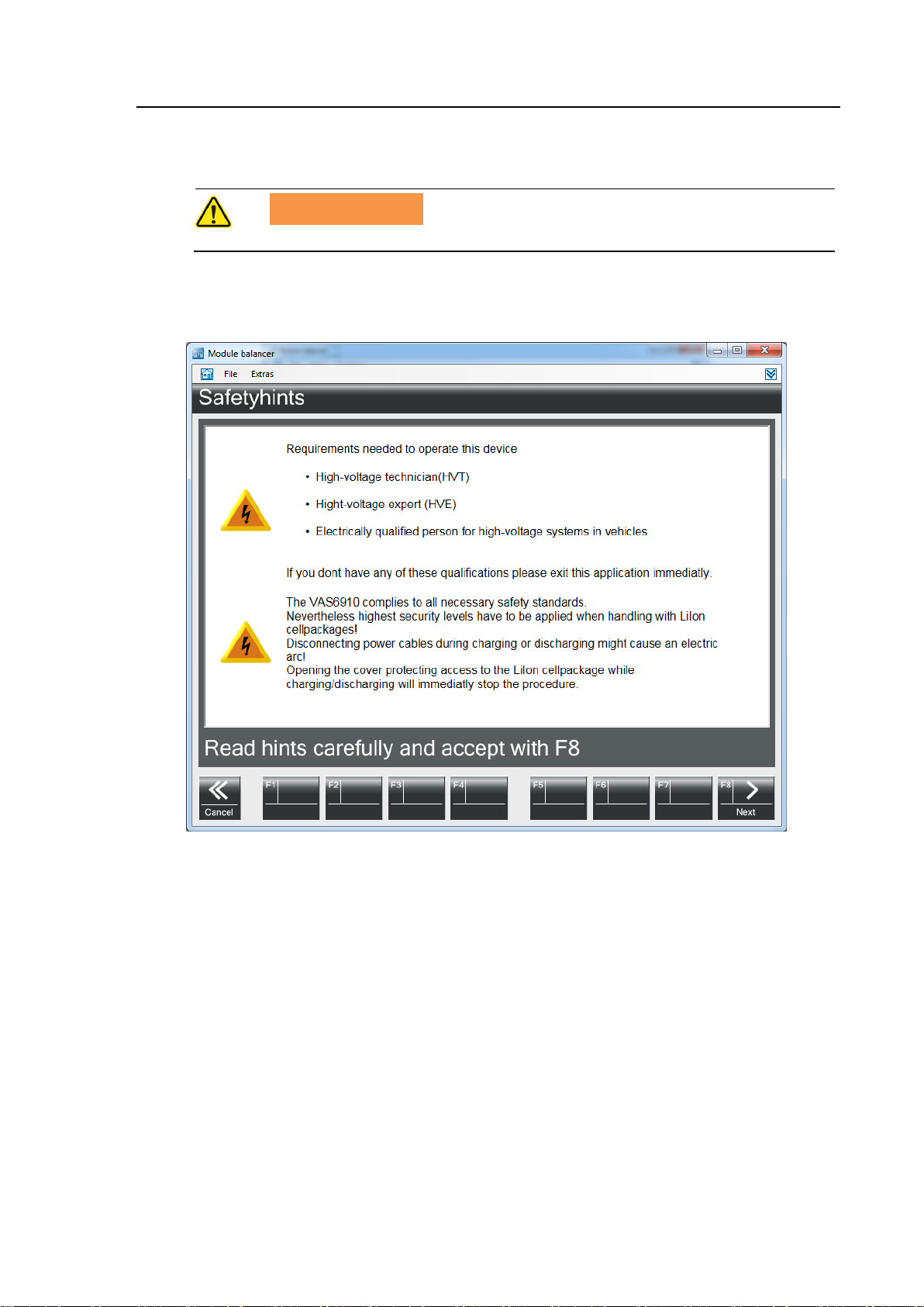
WARNING
Read and follow the safety instructions carefully!
5. A screen with safety instructions is shown next.
6. Please read the instructions and confirm by clicking F8 Next.
Fig. 4-4 Screen with safety instructions
Page 42
Operation
VAS 6910 hardware operating manual V10.00 11/18 All rights reserved.
4-4
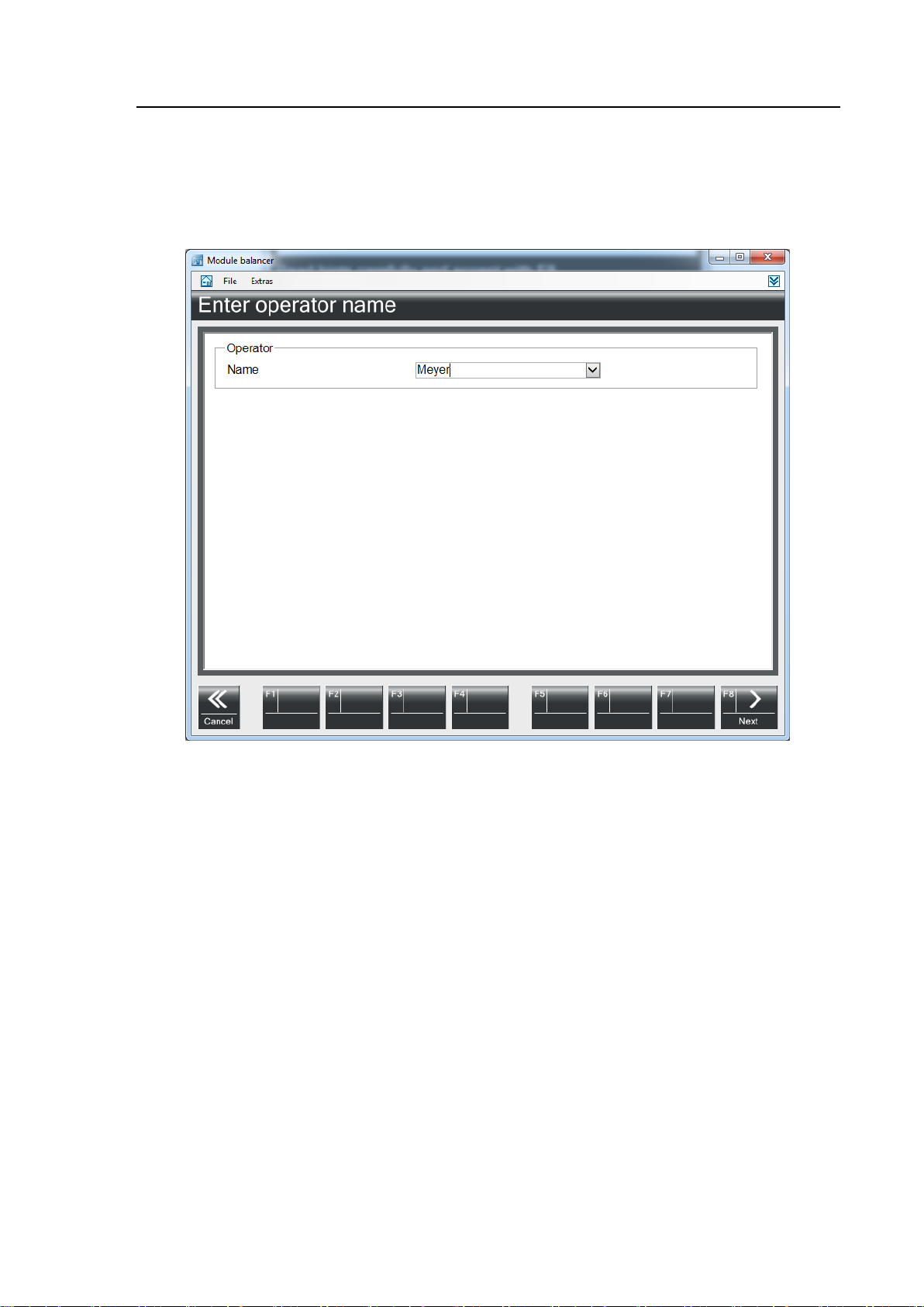
7. Please enter your name. (Input user name, see chapter 4.1.6 “Input user
name“).
8. Continue by clicking F8 Next.
Fig. 4-5 Screen „Enter operator name“
Page 43
Operation
VAS 6910 hardware operating manual V10.00 11/18 All rights reserved.
4-5
2
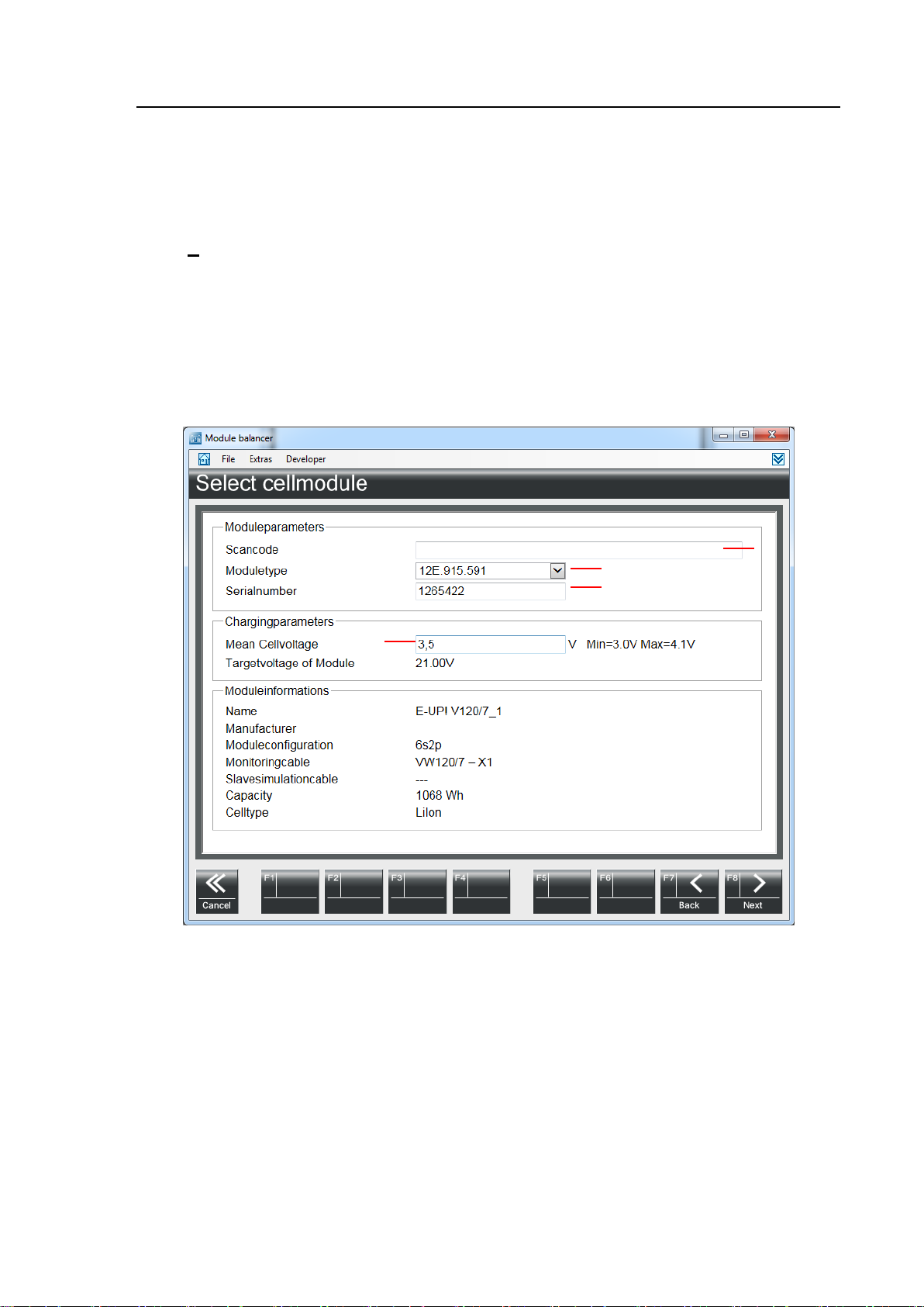
3 4 1
9. Scan the bar code label attached to the cell module.
Field „Scan-code“ (1) shows the scanned cell module information data.
Module type (2) and the serial (3) are filled in automatically.
If no bar code reader is available:
Choose a cell module type from the drop down list (2) and enter a serial number
(3).
Input the avg. cell voltage (4).
This value is given by the VW Off-board diagnostic system.
10. Confirm by clicking F8 Next.
Fig. 4-6 Screen „Select cell module“
Page 44
Operation
VAS 6910 hardware operating manual V10.00 11/18 All rights reserved.
4-6
WARNING
Execute pt. 3 and 4 in the shown order!
WARNUNG
When connecting the cell module, make sure the IR temperature
sensor is not covered and ensure direct visibility between the
sensor and the module.
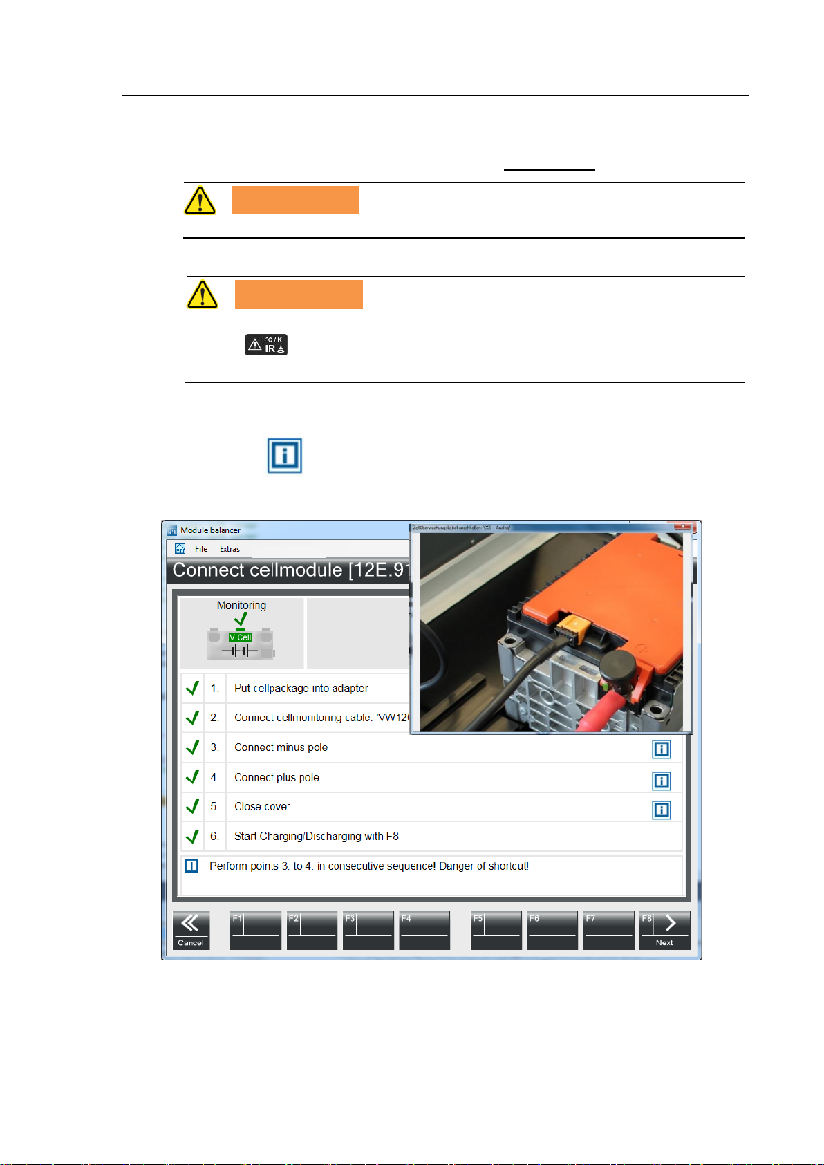
11. The next screen guides you through the connection process.
It is important to do all connecting work in the shown order.
12. Continue by clicking F8 Next.
Click on the button to get a picture schowing where to connect the
cable.
Fig. 4-7 Screen „Connecting the Cell module“
Page 45
Operation
VAS 6910 hardware operating manual V10.00 11/18 All rights reserved.
4-7
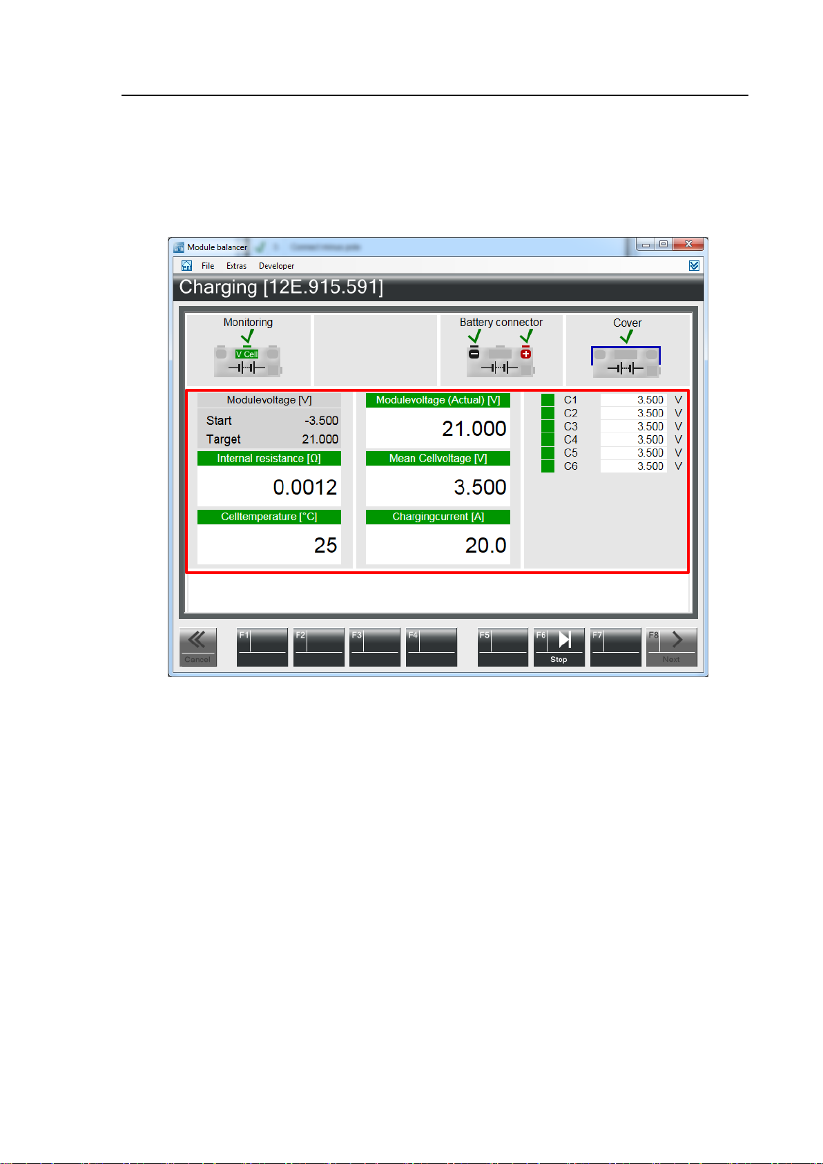
1
13. The cell module gets charged/discharged now.
Section 1 shows all relevant data.
By clicking F6 Stop you can stop the charging / discharging process.
14. After the charging / discharging is finished please click F8 Next.
Fig. 4-8 Screen „Charging/ discharging“
Page 46
Operation
VAS 6910 hardware operating manual V10.00 11/18 All rights reserved.
4-8
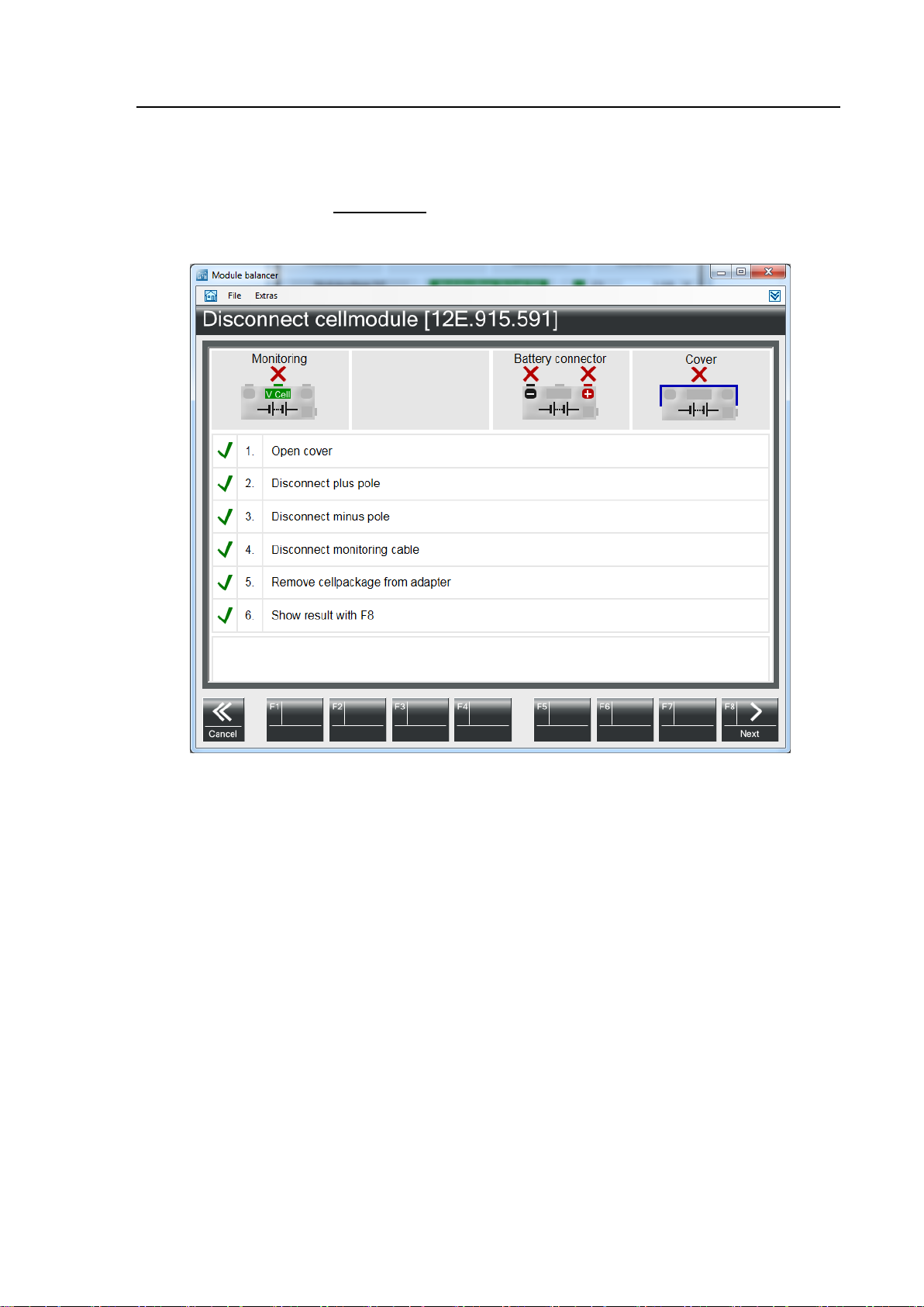
15. A screen appears which shows you how to disconnect the charged /
discharged cell module.
Please follow the exact order shown.
16. Continue with F8 Next.
Fig. 4-9 Screen „Disconnect cell module“
Page 47
Operation
VAS 6910 hardware operating manual V10.00 11/18 All rights reserved.
4-9
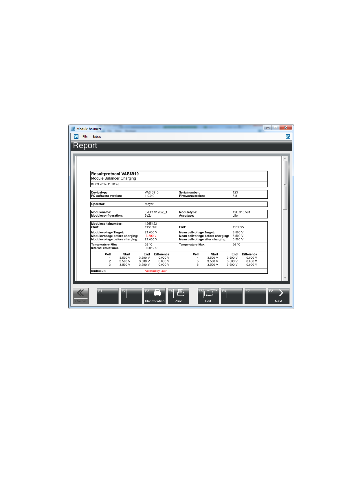
17. On this screen the result protocol is shown.
F4 Print Starts a print out of the protocol.
F5 Edit The protocol can be edited.
18. By pressing F8 Next the charge / discharge process is finished.
Fig. 4-10 Screen „Report“
Page 48
Operation
VAS 6910 hardware operating manual V10.00 11/18 All rights reserved.
4-10
4.1.2 Safety test
1. Start the VAS Manager by selecting: Start│Programs│
DiTEST│VAS DSS.
2. Select Diagnose│Module Balancer.
Fig. 4-11 DSS Manager
3. The start screen appears: Select Safetytest.
Fig. 4-12 Start screen
Page 49
Operation
VAS 6910 hardware operating manual V10.00 11/18 All rights reserved.
4-11
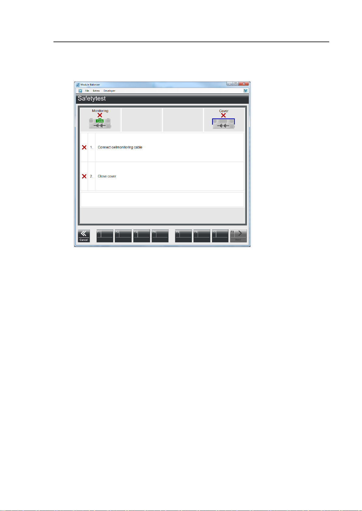
4. Follow the on-screen instructions.
Continue with F8 Next.
Fig. 4-13 Safetytest
Page 50
Operation
VAS 6910 hardware operating manual V10.00 11/18 All rights reserved.
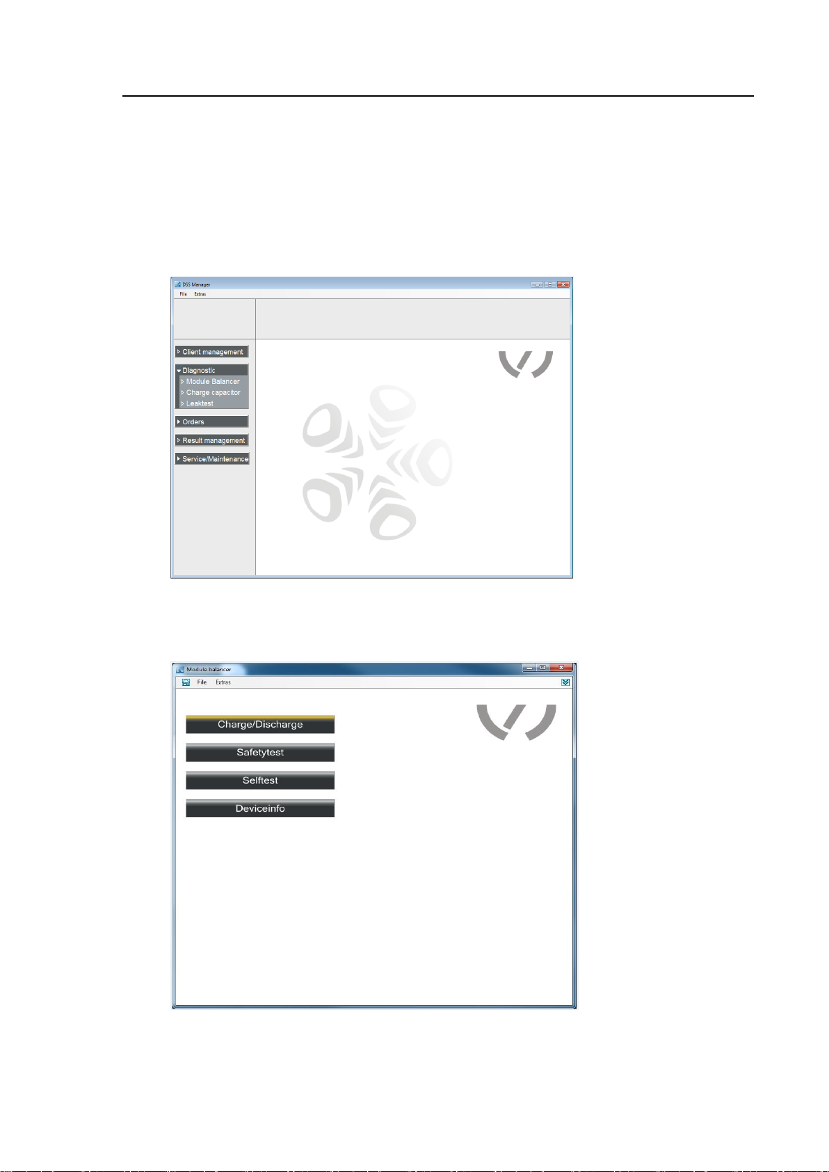
4-12
4.1.3 Self-test
1. Start the VAS Manager by selecting: Start│Programs│
DiTEST│VAS DSS.
2. Select Diagnose│Module Balancer.
Fig. 4-14 DSS Manager
3. The start screen appears: Select Selftest.
Fig. 4-15 Start screen
Page 51
Operation
VAS 6910 hardware operating manual V10.00 11/18 All rights reserved.
4-13
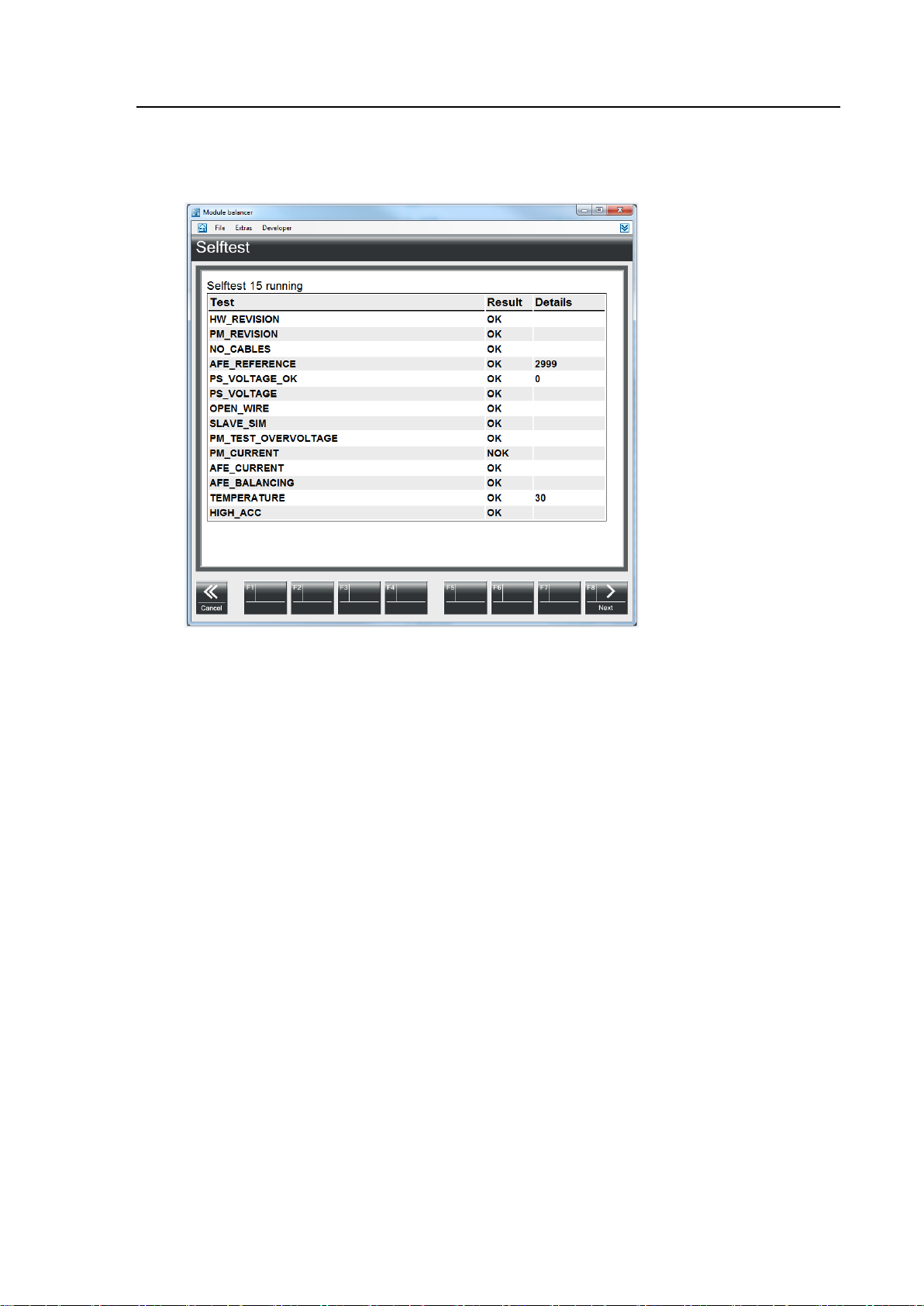
4. The self-test is performed and the result displayed.
Return to the Start screen with F8 Next.
Fig. 4-16 Selftest
Page 52
Operation
VAS 6910 hardware operating manual V10.00 11/18 All rights reserved.
4-14
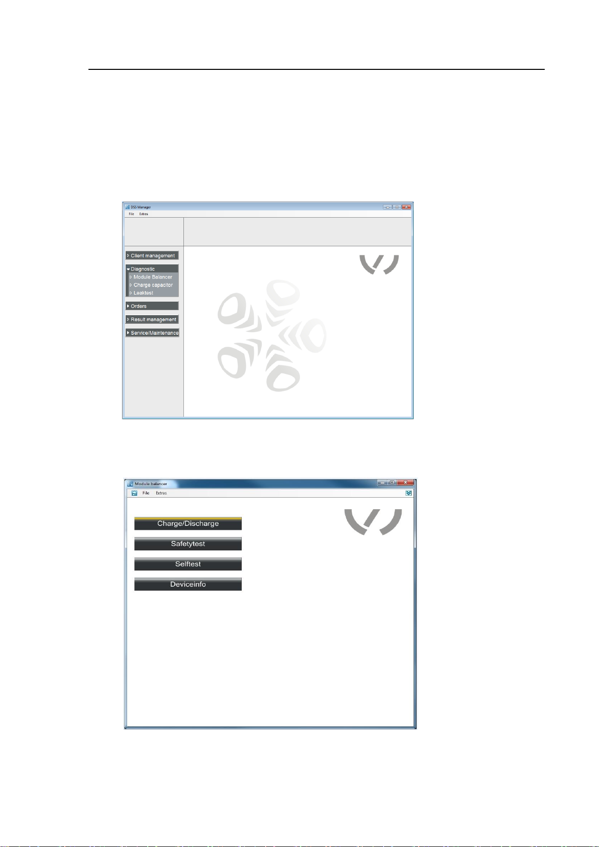
4.1.4 Deviceinfo
1. Start the VAS Manager by selecting: Start│Programs│
DiTEST│VAS DSS.
2. Select Diagnose│Module Balancer.
Fig. 4-17 DSS Manager
3. The start screen appears: Select Deviceinfo.
Fig. 4-18 Start screen
Page 53
Operation
VAS 6910 hardware operating manual V10.00 11/18 All rights reserved.
4-15
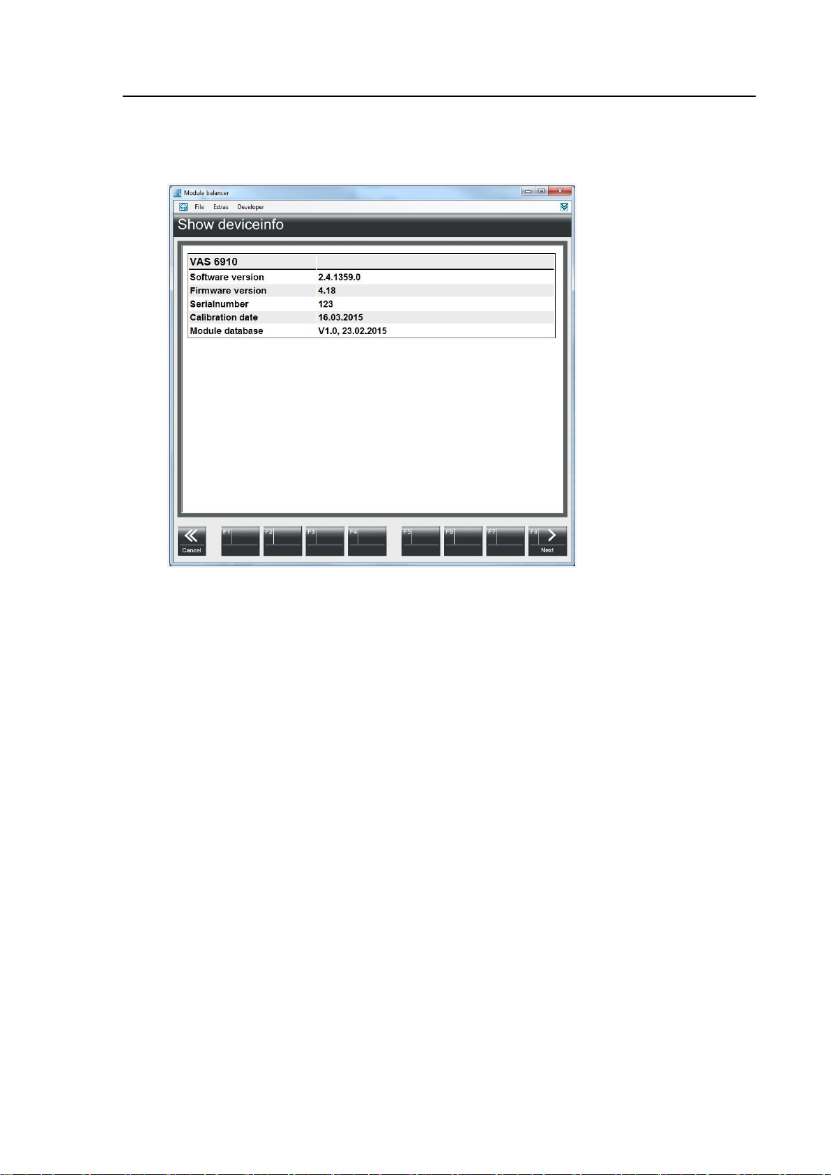
4. A screen appears with the device data.
With F8 Next to the home screen.
Fig. 4-19 Deviceinfo
Page 54
Operation
VAS 6910 hardware operating manual V10.00 11/18 All rights reserved.
4-16
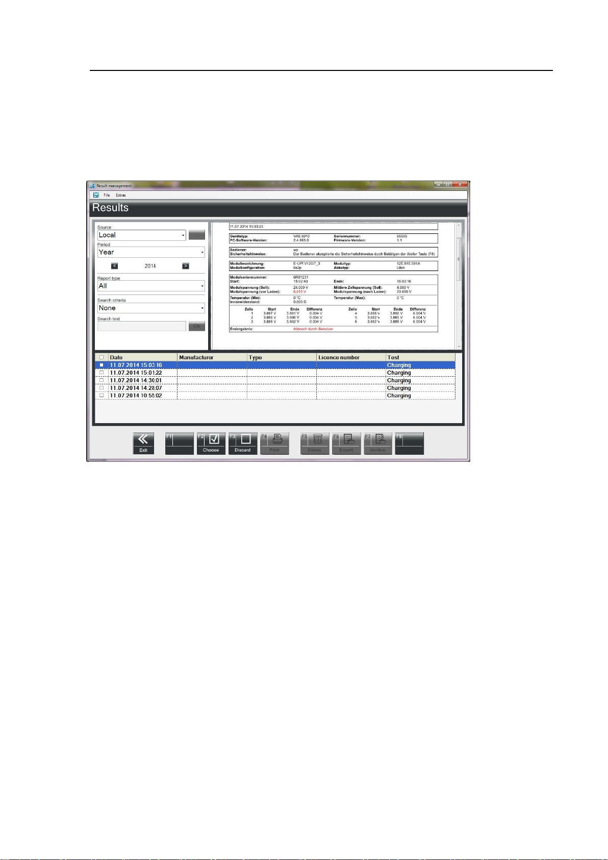
4.1.5 Viewing all reports
With this function you can manage the result protocols.
Click on Result Management.
Fig. 4-10 Result management
Source
Select Local / Network / Saved Results.
Period
Select Day, Week, Month, Year or All.
You can flip forwards and backwards using the arrows.
Report type
Select Proof / Diagnosis Logs etc.
Search text
Choose between “None”, “Manufacturer” or “Licence number”.
In the Search text field, you can narrow the selection down further.
Return to “Results Management” with Quit.
Page 55

Operation
VAS 6910 hardware operating manual V10.00 11/18 All rights reserved.
4-17
Individual logs can be selected by checking a box.
F2 Choose Selects all logs.
F3 Discard Discards the log selection.
F4 Print Prints the selected logs.
F5 Delete Deletes the selected logs.
F6 Export Exports the selected logs.
F5 Directory Opens a window to choose the save location.
Choose a location and then click OK.
F8 Next Starts the export.
F7 Archive Archives the selected logs.
The archived logs will be deleted from the internal database.
F5 Directory Opens a window to choose the save location.
Choose a location and then click OK.
F8 Next Starts the archiving.
<< Cancel Quits the results display.
Page 56
Operation
VAS 6910 hardware operating manual V10.00 11/18 All rights reserved.
4-18
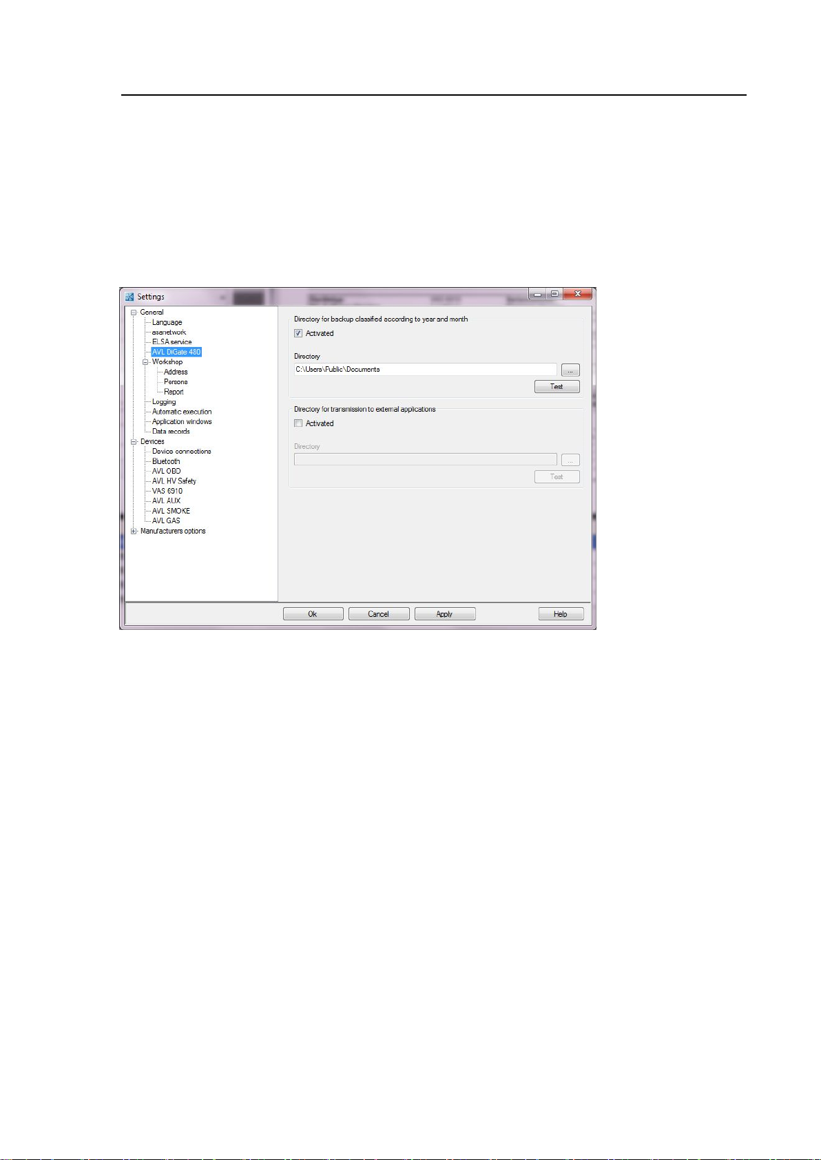
4.1.6 Result report directory
Result protocols are stored for future use at the default location:
“C:\Users\Public\Documents\xxxx“.
This location can be changed:
Click on ExtrasSettingsAVL DiGate480.
Fig. 4-11 Changing the Report protocol directory
Page 57

Operation
VAS 6910 hardware operating manual V10.00 11/18 All rights reserved.
4-19
4.1.7 Entering a list of operator names
Using this function you can manage a list of operator names.
The list appears in operation mode charge/discharge, see Fig.4-5.
Click on ExtrasSettingsPersons (see chapter 4-11).
Clicking New opens an input window into which you can enter the
name of a new tester.
Return to “Tester” with OK.
Clicking Delete deletes the blue-highlighted operator name.
Clicking Edit opens an input window in which you can edit the
blue-highlighted tester name.
Return to “Tester” with OK.
Clicking Current Operator selects the blue-highlighted operator name
(or clicking the desired operator name).
Clicking Responsible Operator selects the blue-highlighted tester name
(or clicking the desired operator name).
4.1.8 Switch off
The VAS 6910 has no on/off switch.
With the button, see fig. 2-8, only the power modules are switched off. The VAS 6910
enters Idle, Sleep mode.
To disconnect the VAS 6910 from the power grid press the red button (Power module
off) and disconnect the power cable from the wall outlet.
Page 58
Troubleshooting
VAS 6910 hardware operating manual V10.00 11/18 All rights reserved.
5-1
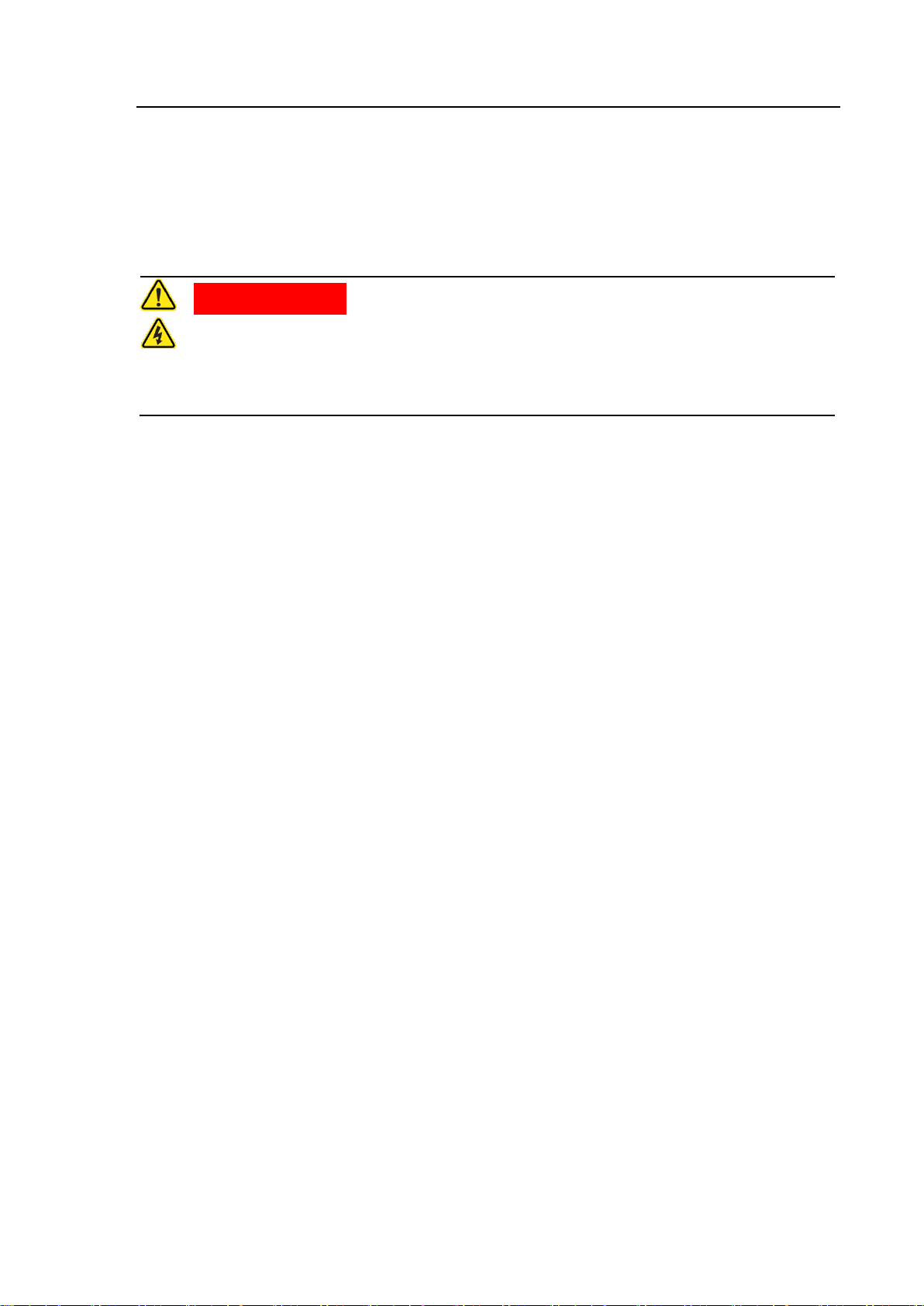
DANGER
Danger to life by electrical shock
Maintenance is only allowed by service staff!
Do not open the VAS 6910, because exposed parts can have dangerous voltages!
5 Troubleshooting
Maintenance
Page 59
Maintenance and care
VAS 6910 hardware operating manual V10.00 11/18 All rights reserved.
6-1
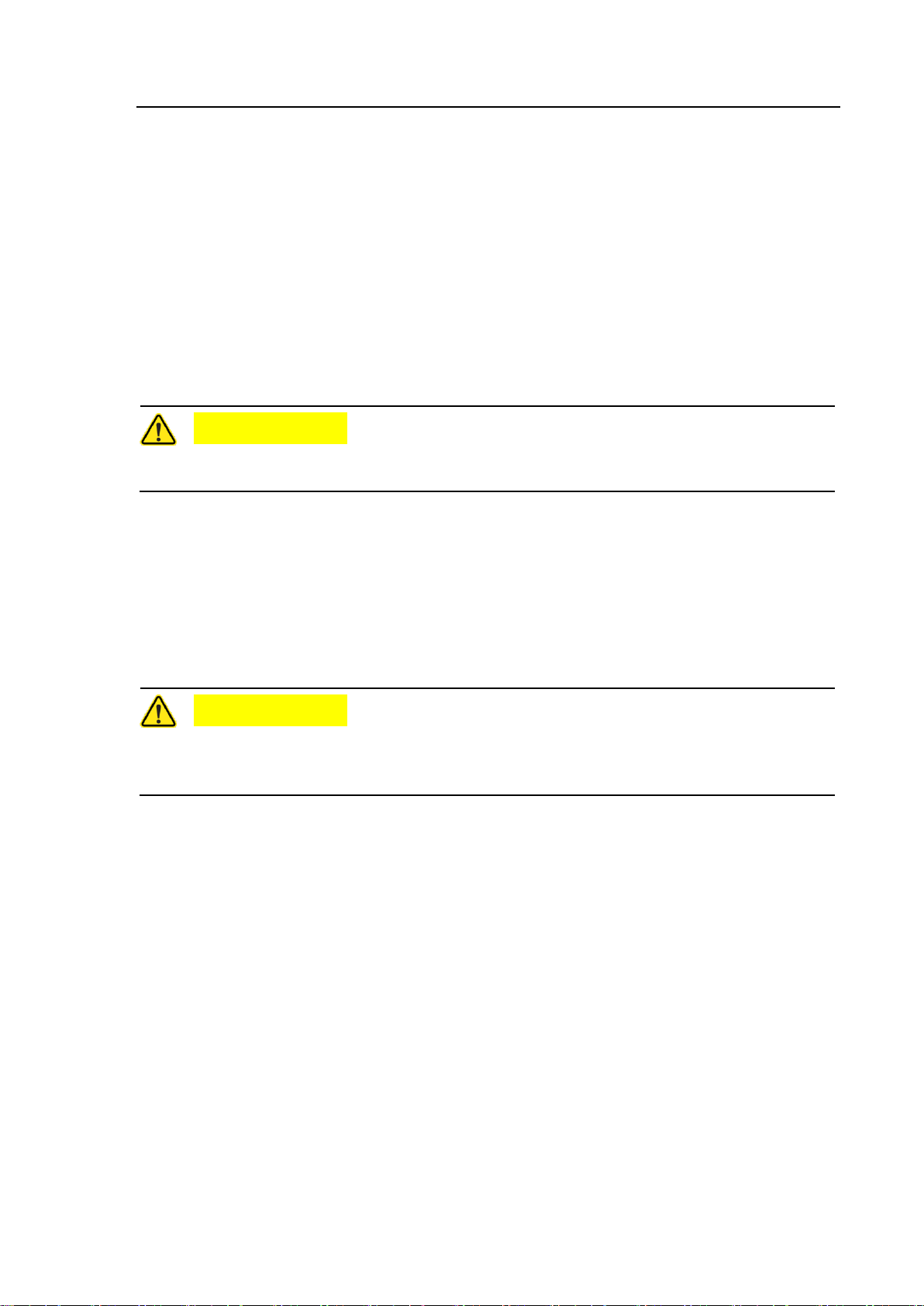
CAUTION
Damaged Parts (power cord, adapter and US cables) have to be exchanged
immediately!
CAUTION
Before cleaning the VAS 6910, switch off the Power module and remove the mains
plug! Remove all adapter cables!
Be sure that no liquid is flowing into the housing of the VAS 6910!
6 Maintenance and care
6.1 Optical check
Carry out a regular optical check of the VAS 6910, USB cable and measuring cables
with the test adapters.
Check for damage and dirt.
6.2 Cleaning
If the housing is dirty and you want to clean it, please use a dry cloth.
Page 60

Technical data
VAS 6910 hardware operating manual V10.00 11/18 All rights reserved.
7-1
AC-Power grid
Nominal voltage range
Power supply
Frequency
Power consumption
100 … 240 V~
50 ... 60 Hz
2,15 kW
Charging power
max. 2 kW (max. Current: 50 A)
Discharging power
max. 400 W (max. Current: 10 A)
Cell monitoring
(charge/Discharge)
Depends on type of cell module:
- Analogue meas. of cell voltages and temperatures
- Monitoring via CAN bus to the cell module controller
Monitored values are Voltages, currents and
temperatures.
External interface
USB
USB 2.0-Rugged
Ambient conditions
Operating
Transport and storage
Ambient temperature
Relative humidity
Ambient temperature
Relative humidity
0 to +40 °C
at max. +25 °C
10 to 80 %
non condensing
-20 to +55 °C
at max. +20 °C
10 to 80 %,
non condensing
Electrical protection and
storage
Safety regulations
Measurement device: DIN EN 61010-1 (VDE 0411 part 1)
IEC 1010-1
Garage equipment: UL 201 GARAGE-EQUIPMENT
- Protection class I
- Degree of protection IP30
7 Technical data
7.1 Operating data
Page 61

Fault reportfax
VAS 6910 hardware operating manual V10.00 11/18 All rights reserved.
8-1
8 Fault report fax
Fax No.:
Please fill in the relevant sections completely (if possible in English, French or
German) and then fax it to the relevant regional service centre, see Service
information, chapt. 3-1 Regional service centres.
1. Registration details
Serial number
Is your warranty still valid (24 months)? Ja
If yes, please enclose the guarantee proof (registration and delivery receipt as a
copy)
2. Dealership details
VW-affiliate workshop Independent workshop
Sales centre / importer no.
Name of company Tax ID no.
Contact person Telephone / Fax
Postal address: Delivery address (if different to postal address):
Street No. Street No.
Postal code City Postal code City
Country Country
Phone-No. Phone-No.
Fax. Fax.
1. As to be entered / already entered on the tester (see Operating Manual)
2. For EU countries only
Please provide additional information as requested on the following page.
1
Dealership number1
2
Page 62

Fault report
VAS 6910 hardware operating manual V10.00 11/18 All rights reserved.
8-2
Fault report fax, second page
3. Description of problem
Basic problems
Was the start-up dialogue box displayed on-screen? Yes ❏
Can you load/launch the calibration program? Yes ❏
Does the fault relate to the USB port? Yes ❏
Fault image or error message:
Is it possible that an adaption cable causes the error? Yes ❏
(see sections 2 and 4 of the operating manual)
❏ VAS 6910/1 ❏ VAS 6910/11
❏ VAS 6910/2 ❏ VAS 6910/12A
❏ VAS 611003 ❏ VAS 6910/13
❏ VAS 611001 ❏ VAS 6910/14
❏ VAS 6910/5 ❏ VAS 6910/15
❏ VAS 6161/1 ❏ VAS 6910/16
❏ VAS 6161/10 ❏ VAS 6910/17
Is the fault reproducible? Yes ❏
Does the fault occur sporadically? Yes ❏
What software firmware versions are you running?
(Choose from VAS-Manager Service/Maintenance>System-info>without devices)
Module Balancer:
Please provide additional information as requested on the following page.
Page 63

Fault report
VAS 6910 hardware operating manual V10.00 11/18 All rights reserved.
8-3
Fault report fax, third page
In which operating mode did the fault occur?
During charging? Yes ❏
During discharging? Yes ❏
While in safety test? Yes ❏
When self-test was running? Yes ❏
Last message text in the calibration program:
(see „Program hints"‘ box)
Space for further messages:
Does the fault report fax have any attachments?
Screenshot with error messages? Yes ❏
We have read the service conditions for the replacement of components and we
hereby accept these conditions.
City Date Signature Stamp
Page 64

Index
VAS 6910 hardware operating manual V10.00 11/18 All rights reserved.
9-1
9 Index
A
Associated Documents 1-5
C
Cable sets 2-11
Certificate of Calibration 1-2
Charging / Discharging 4-1
Cleaning 6-1
Commissioning 3-1
Components 2-1
D
Designated Use 1-4
E
Entering a list of operator
names 4-15
Explanation of symbols i
F
Fault report fax 8-1
Field of application 1-4
M
Maintenance 5-1
Maintenance and care 6-1
O
Operating data 7-1
Operation 4-1
Optical check 6-1
P
Preparation 4-1
R
Result report directory 4-14
S
Safety Instructions i
Safety Notes 1-2
Safety test 4-10
Scope of delivery 2-16
Self-test 4-11
Switch off 4-16
G
General Information 1-1
General Notes 1-1
T
Technical data 7-1
Troubleshooting 5-1
V
VAS 6910 Module-Balancer 2-6
Viewing all reports 4-12
Page 65

VAS 6910 hardware operating manual V10.00 11/18 All rights reserved.
9-2
We have checked the contents of the
documentation to ensure they
correspond to the status described.
Nevertheless deviations cannot be
entirely excluded and we cannot
therefore guarantee complete
agreement. The information in this
documentation is however regularly
reviewed and any corrections
necessary will be incorporated in the
next edition. We will be grateful to
receive suggestions for improvement.
Products are subject to alterations in
shape, equipment and design. For this
reason, no claims may be made on the
basis of the information, graphics and
descriptions contained in this operating
manual. Reprints, copies and
translations of this document, in whole or
in part, may not be undertaken without
the express written consent of
Volkswagen AG and/or the manufacturer
with the exception that the user
documentation may be supplied with
each tester. Making available to third
parties is not permitted. All rights
provided under copyright law are
expressly reserved by Volkswagen AG
and the manufacturer. Subject to
alteration. All rights reserved.
VOLKSWAGEN AG
KD-WERKSTATTAUSRÜSTUNG
D-38436 Wolfsburg
Copyright Volkswagen AG 2018,
AVL DiTEST 2018
Manufacturer:
AVL DiTEST GmbH
Alte Poststrasse 156
8020 Graz
AUSTRIA
All rights reserved.
 Loading...