

Page 1
Service
Repair Manual
Golf 2015 ➤
Golf Variant 2015 ➤
Body Exterior
Edition 02.2016
Service Department. Technical Information
Page 2

List of Workshop Manual Repair Groups
Re pa ir G ro up
50 - Body Front
55 - Hood, Lids
57 - Front Doors, Central Locking System
58 - Rear Doors
60 - Sunroof
63 - Bumpers
64 - Glass, Window Regulators
66 - Exterior Equipment
Service
Technical information should always be available to the foremen and mechanics, because their
careful and constant adherence to the instructions is essential to ensure vehicle road-worthiness and
safety. In addition, the normal basic safety precautions for working on motor vehicles must, as a
matter of course, be observed.
Page 3

Golf 2015 ➤ , Golf Variant 2015 ➤
Body Exterior - Edition 02.2016
Contents
50 - Body Front . . . . . . . . . . . . . . . . . . . . . . . . . . . . . . . . . . . . . . . . . . . . . . . . . . . . . . 1
1 Lock Carrier . . . . . . . . . . . . . . . . . . . . . . . . . . . . . . . . . . . . . . . . . . . . . . . . . . . . . . . . . . . . 1
1.1 Overview - Lock Carrier . . . . . . . . . . . . . . . . . . . . . . . . . . . . . . . . . . . . . . . . . . . . . . . . . . . . 1
1.2 Lock Carrier, Removing and Installing . . . . . . . . . . . . . . . . . . . . . . . . . . . . . . . . . . . . . . . . 2
1.3 Service Position, Implementing and Resetting . . . . . . . . . . . . . . . . . . . . . . . . . . . . . . . . . . 4
1.4 Lock Carrier, Servicing . . . . . . . . . . . . . . . . . . . . . . . . . . . . . . . . . . . . . . . . . . . . . . . . . . . . 7
2 Fender . . . . . . . . . . . . . . . . . . . . . . . . . . . . . . . . . . . . . . . . . . . . . . . . . . . . . . . . . . . . . . . . 10
2.1 Overview - Fender . . . . . . . . . . . . . . . . . . . . . . . . . . . . . . . . . . . . . . . . . . . . . . . . . . . . . . . . 10
2.2 Overview - Deformation Element . . . . . . . . . . . . . . . . . . . . . . . . . . . . . . . . . . . . . . . . . . . . 11
2.3 Fender, Removing and Installing . . . . . . . . . . . . . . . . . . . . . . . . . . . . . . . . . . . . . . . . . . . . 11
2.4 Fender Brace, Removing and Installing . . . . . . . . . . . . . . . . . . . . . . . . . . . . . . . . . . . . . . . . 14
3 Bulkhead . . . . . . . . . . . . . . . . . . . . . . . . . . . . . . . . . . . . . . . . . . . . . . . . . . . . . . . . . . . . . . 16
3.1 Overview - Bulkhead . . . . . . . . . . . . . . . . . . . . . . . . . . . . . . . . . . . . . . . . . . . . . . . . . . . . . . 16
3.2 Overview - Plenum Chamber Cover . . . . . . . . . . . . . . . . . . . . . . . . . . . . . . . . . . . . . . . . . . 17
3.3 Bulkhead, Removing and Installing . . . . . . . . . . . . . . . . . . . . . . . . . . . . . . . . . . . . . . . . . . 17
3.4 Plenum Chamber Cover, Removing and Installing . . . . . . . . . . . . . . . . . . . . . . . . . . . . . . 19
4 Special Tools . . . . . . . . . . . . . . . . . . . . . . . . . . . . . . . . . . . . . . . . . . . . . . . . . . . . . . . . . . . . 22
55 - Hood, Lids . . . . . . . . . . . . . . . . . . . . . . . . . . . . . . . . . . . . . . . . . . . . . . . . . . . . . . 24
1 Hood . . . . . . . . . . . . . . . . . . . . . . . . . . . . . . . . . . . . . . . . . . . . . . . . . . . . . . . . . . . . . . . . . . 24
1.1 Overview - Hood . . . . . . . . . . . . . . . . . . . . . . . . . . . . . . . . . . . . . . . . . . . . . . . . . . . . . . . . . . 24
1.2 Overview - Release Cable . . . . . . . . . . . . . . . . . . . . . . . . . . . . . . . . . . . . . . . . . . . . . . . . . . 26
1.3 Hood, Removing and Installing . . . . . . . . . . . . . . . . . . . . . . . . . . . . . . . . . . . . . . . . . . . . . . 26
1.4 Hood, Adjusting . . . . . . . . . . . . . . . . . . . . . . . . . . . . . . . . . . . . . . . . . . . . . . . . . . . . . . . . . . 28
1.5 Latch, Removing and Installing . . . . . . . . . . . . . . . . . . . . . . . . . . . . . . . . . . . . . . . . . . . . . . 31
1.6 Latch, Adjusting . . . . . . . . . . . . . . . . . . . . . . . . . . . . . . . . . . . . . . . . . . . . . . . . . . . . . . . . . . 33
1.7 Hood Release Lever, Removing and Installing . . . . . . . . . . . . . . . . . . . . . . . . . . . . . . . . . . 35
1.8 Catch, Removing and Installing . . . . . . . . . . . . . . . . . . . . . . . . . . . . . . . . . . . . . . . . . . . . . . 36
1.9 Catch, Adjusting . . . . . . . . . . . . . . . . . . . . . . . . . . . . . . . . . . . . . . . . . . . . . . . . . . . . . . . . . . 38
1.10 Hinges, Removing and Installing . . . . . . . . . . . . . . . . . . . . . . . . . . . . . . . . . . . . . . . . . . . . 39
1.11 Insulation, Removing and Installing . . . . . . . . . . . . . . . . . . . . . . . . . . . . . . . . . . . . . . . . . . 41
1.12 Gas-Filled Strut, Removing and Installing . . . . . . . . . . . . . . . . . . . . . . . . . . . . . . . . . . . . . . 44
1.13 Gas-Filled Strut, Venting . . . . . . . . . . . . . . . . . . . . . . . . . . . . . . . . . . . . . . . . . . . . . . . . . . 45
1.14 Release Cable, Removing and Installing . . . . . . . . . . . . . . . . . . . . . . . . . . . . . . . . . . . . . . 45
2 Rear Lid . . . . . . . . . . . . . . . . . . . . . . . . . . . . . . . . . . . . . . . . . . . . . . . . . . . . . . . . . . . . . . . . 49
2.1 Overview - Rear Lid . . . . . . . . . . . . . . . . . . . . . . . . . . . . . . . . . . . . . . . . . . . . . . . . . . . . . . 49
2.2 Rear Lid, Removing and Installing . . . . . . . . . . . . . . . . . . . . . . . . . . . . . . . . . . . . . . . . . . . . 50
2.3 Rear Lid, Adjusting . . . . . . . . . . . . . . . . . . . . . . . . . . . . . . . . . . . . . . . . . . . . . . . . . . . . . . . . 55
2.4 Adjusting Buffer, Removing and Installing . . . . . . . . . . . . . . . . . . . . . . . . . . . . . . . . . . . . . . 56
2.5 Adjusting Buffer, Adjusting . . . . . . . . . . . . . . . . . . . . . . . . . . . . . . . . . . . . . . . . . . . . . . . . . . 57
2.6 Latch, Removing and Installing . . . . . . . . . . . . . . . . . . . . . . . . . . . . . . . . . . . . . . . . . . . . . . 58
2.7 Actuator, Removing and Installing . . . . . . . . . . . . . . . . . . . . . . . . . . . . . . . . . . . . . . . . . . . . 60
2.8 Hinges, Removing and Installing . . . . . . . . . . . . . . . . . . . . . . . . . . . . . . . . . . . . . . . . . . . . 64
2.9 Catch, Removing and Installing . . . . . . . . . . . . . . . . . . . . . . . . . . . . . . . . . . . . . . . . . . . . . . 66
2.10 Catch, Adjusting . . . . . . . . . . . . . . . . . . . . . . . . . . . . . . . . . . . . . . . . . . . . . . . . . . . . . . . . . . 67
2.11 Rear Lid Seal, Removing and Installing . . . . . . . . . . . . . . . . . . . . . . . . . . . . . . . . . . . . . . . . 68
2.12 Gas-Filled Strut, Removing and Installing . . . . . . . . . . . . . . . . . . . . . . . . . . . . . . . . . . . . . . 70
2.13 Gas-Filled Strut, Venting . . . . . . . . . . . . . . . . . . . . . . . . . . . . . . . . . . . . . . . . . . . . . . . . . . 72
3 Fuel Filler Door Unit . . . . . . . . . . . . . . . . . . . . . . . . . . . . . . . . . . . . . . . . . . . . . . . . . . . . . . 73
3.1 Overview - Fuel Filler Door Unit . . . . . . . . . . . . . . . . . . . . . . . . . . . . . . . . . . . . . . . . . . . . . . 73
3.2 Fuel Filler Door Unit, Removing and Installing . . . . . . . . . . . . . . . . . . . . . . . . . . . . . . . . . . 74
3.3 Fuel Filler Door, Removing and Installing . . . . . . . . . . . . . . . . . . . . . . . . . . . . . . . . . . . . . . 76
Contents i
Page 4

Golf 2015 ➤ , Golf Variant 2015 ➤
Body Exterior - Edition 02.2016
3.4 Adjusting Element, Removing and Installing . . . . . . . . . . . . . . . . . . . . . . . . . . . . . . . . . . . . 77
4 Special Tools . . . . . . . . . . . . . . . . . . . . . . . . . . . . . . . . . . . . . . . . . . . . . . . . . . . . . . . . . . . . 78
57 - Front Doors, Central Locking System . . . . . . . . . . . . . . . . . . . . . . . . . . . . . . . . . . 79
1 Door . . . . . . . . . . . . . . . . . . . . . . . . . . . . . . . . . . . . . . . . . . . . . . . . . . . . . . . . . . . . . . . . . . 79
1.1 Overview - Door . . . . . . . . . . . . . . . . . . . . . . . . . . . . . . . . . . . . . . . . . . . . . . . . . . . . . . . . . . 79
1.2 Inner Door Seal, Removing and Installing . . . . . . . . . . . . . . . . . . . . . . . . . . . . . . . . . . . . . . 82
1.3 Outer Door Seal, Removing and Installing . . . . . . . . . . . . . . . . . . . . . . . . . . . . . . . . . . . . . . 84
1.4 Door, Removing and Installing . . . . . . . . . . . . . . . . . . . . . . . . . . . . . . . . . . . . . . . . . . . . . . 86
1.5 Door, Adjusting . . . . . . . . . . . . . . . . . . . . . . . . . . . . . . . . . . . . . . . . . . . . . . . . . . . . . . . . . . 89
1.6 Catch, Adjusting . . . . . . . . . . . . . . . . . . . . . . . . . . . . . . . . . . . . . . . . . . . . . . . . . . . . . . . . . . 91
1.7 Door Arrester, Removing and Installing . . . . . . . . . . . . . . . . . . . . . . . . . . . . . . . . . . . . . . . . 93
2 Door Components . . . . . . . . . . . . . . . . . . . . . . . . . . . . . . . . . . . . . . . . . . . . . . . . . . . . . . . . 95
2.1 Overview - Door Components . . . . . . . . . . . . . . . . . . . . . . . . . . . . . . . . . . . . . . . . . . . . . . 95
2.2 Overview - Window Regulator . . . . . . . . . . . . . . . . . . . . . . . . . . . . . . . . . . . . . . . . . . . . . . 97
2.3 Overview - Door Handle and Door Lock . . . . . . . . . . . . . . . . . . . . . . . . . . . . . . . . . . . . . . . . 98
2.4 Window Regulator Motor, Removing and Installing . . . . . . . . . . . . . . . . . . . . . . . . . . . . . . 99
2.5 Window Regulator, Removing and Installing . . . . . . . . . . . . . . . . . . . . . . . . . . . . . . . . . . . . 101
2.6 Door Inner Cover, Removing and Installing . . . . . . . . . . . . . . . . . . . . . . . . . . . . . . . . . . . . 104
2.7 Catch, Removing and Installing . . . . . . . . . . . . . . . . . . . . . . . . . . . . . . . . . . . . . . . . . . . . . . 106
2.8 Lock Cylinder Cap, Removing and Installing . . . . . . . . . . . . . . . . . . . . . . . . . . . . . . . . . . . . 106
2.9 Cap without Lock Cylinder, Removing and Installing . . . . . . . . . . . . . . . . . . . . . . . . . . . . . . 108
2.10 Lock Cylinder, Removing and Installing . . . . . . . . . . . . . . . . . . . . . . . . . . . . . . . . . . . . . . . . 112
2.11 Door Handle, Removing and Installing . . . . . . . . . . . . . . . . . . . . . . . . . . . . . . . . . . . . . . . . 114
2.12 Bracket, Removing and Installing . . . . . . . . . . . . . . . . . . . . . . . . . . . . . . . . . . . . . . . . . . . . 116
2.13 Door Lock, Removing and Installing . . . . . . . . . . . . . . . . . . . . . . . . . . . . . . . . . . . . . . . . . . 119
2.14 Window Guide, Removing and Installing . . . . . . . . . . . . . . . . . . . . . . . . . . . . . . . . . . . . . . 124
2.15 Outer Window Shaft Strip, Removing and Installing . . . . . . . . . . . . . . . . . . . . . . . . . . . . . . 126
2.16 Inner Window Shaft Strip, Removing and Installing . . . . . . . . . . . . . . . . . . . . . . . . . . . . . . 129
2.17 Outer Cover, Removing and Installing . . . . . . . . . . . . . . . . . . . . . . . . . . . . . . . . . . . . . . . . 130
3 Central Locking . . . . . . . . . . . . . . . . . . . . . . . . . . . . . . . . . . . . . . . . . . . . . . . . . . . . . . . . . . 132
3.1 Component Location Overview - Central Locking . . . . . . . . . . . . . . . . . . . . . . . . . . . . . . . . 132
3.2 Driver Door Control Module J386 and Front Passenger Door Control Module J387 , Removing
and Installing . . . . . . . . . . . . . . . . . . . . . . . . . . . . . . . . . . . . . . . . . . . . . . . . . . . . . . . . . . . . 137
3.3 Driver Side Rear Window Regulator Motor Control Module J1016 and Front Passenger Side
Rear Window Regulator Motor Control Module J1017 , Removing and Installing . . . . . . . . 137
3.4 Key Battery, Removing and Installing . . . . . . . . . . . . . . . . . . . . . . . . . . . . . . . . . . . . . . . . 137
3.5 Ignition Key Cap, Removing and Installing . . . . . . . . . . . . . . . . . . . . . . . . . . . . . . . . . . . . . . 140
4 Special Tools . . . . . . . . . . . . . . . . . . . . . . . . . . . . . . . . . . . . . . . . . . . . . . . . . . . . . . . . . . . . 141
58 - Rear Doors . . . . . . . . . . . . . . . . . . . . . . . . . . . . . . . . . . . . . . . . . . . . . . . . . . . . . . 143
1 Door . . . . . . . . . . . . . . . . . . . . . . . . . . . . . . . . . . . . . . . . . . . . . . . . . . . . . . . . . . . . . . . . . . 143
1.1 Overview - Door . . . . . . . . . . . . . . . . . . . . . . . . . . . . . . . . . . . . . . . . . . . . . . . . . . . . . . . . . . 143
1.2 Door, Removing and Installing . . . . . . . . . . . . . . . . . . . . . . . . . . . . . . . . . . . . . . . . . . . . . . 145
1.3 Door, Adjusting . . . . . . . . . . . . . . . . . . . . . . . . . . . . . . . . . . . . . . . . . . . . . . . . . . . . . . . . . . 149
1.4 Catch, Adjusting . . . . . . . . . . . . . . . . . . . . . . . . . . . . . . . . . . . . . . . . . . . . . . . . . . . . . . . . . . 151
1.5 Door Arrester, Removing and Installing . . . . . . . . . . . . . . . . . . . . . . . . . . . . . . . . . . . . . . . . 152
1.6 Inner Door Seal, Removing and Installing . . . . . . . . . . . . . . . . . . . . . . . . . . . . . . . . . . . . . . 154
1.7 Outer Door Seal, Removing and Installing . . . . . . . . . . . . . . . . . . . . . . . . . . . . . . . . . . . . . . 157
2 Door Components . . . . . . . . . . . . . . . . . . . . . . . . . . . . . . . . . . . . . . . . . . . . . . . . . . . . . . . . 159
2.1 Overview - Door Components . . . . . . . . . . . . . . . . . . . . . . . . . . . . . . . . . . . . . . . . . . . . . . 159
2.2 Overview - Window Regulator . . . . . . . . . . . . . . . . . . . . . . . . . . . . . . . . . . . . . . . . . . . . . . 161
2.3 Overview - Door Handle and Door Lock . . . . . . . . . . . . . . . . . . . . . . . . . . . . . . . . . . . . . . . . 162
2.4 Window Regulator Motor, Removing and Installing . . . . . . . . . . . . . . . . . . . . . . . . . . . . . . 163
2.5 Window Regulator, Removing and Installing . . . . . . . . . . . . . . . . . . . . . . . . . . . . . . . . . . . . 165
ii Contents
Page 5

Golf 2015 ➤ , Golf Variant 2015 ➤
Body Exterior - Edition 02.2016
2.6 Window Crank, Removing and Installing . . . . . . . . . . . . . . . . . . . . . . . . . . . . . . . . . . . . . . 168
2.7 Window Crank, Removing and Installing . . . . . . . . . . . . . . . . . . . . . . . . . . . . . . . . . . . . . . 168
2.8 Door Inner Cover, Removing and Installing . . . . . . . . . . . . . . . . . . . . . . . . . . . . . . . . . . . . 170
2.9 Catch, Removing and Installing . . . . . . . . . . . . . . . . . . . . . . . . . . . . . . . . . . . . . . . . . . . . . . 172
2.10 Cap, Removing and Installing . . . . . . . . . . . . . . . . . . . . . . . . . . . . . . . . . . . . . . . . . . . . . . 173
2.11 Door Handle, Removing and Installing . . . . . . . . . . . . . . . . . . . . . . . . . . . . . . . . . . . . . . . . 176
2.12 Bracket, Removing and Installing . . . . . . . . . . . . . . . . . . . . . . . . . . . . . . . . . . . . . . . . . . . . 177
2.13 Door Lock, Removing and Installing . . . . . . . . . . . . . . . . . . . . . . . . . . . . . . . . . . . . . . . . . . 179
2.14 Window Guide, Removing and Installing . . . . . . . . . . . . . . . . . . . . . . . . . . . . . . . . . . . . . . 183
2.15 Outer Window Shaft Strip, Removing and Installing . . . . . . . . . . . . . . . . . . . . . . . . . . . . . . 186
2.16 Inner Window Shaft Strip, Removing and Installing . . . . . . . . . . . . . . . . . . . . . . . . . . . . . . 187
2.17 Outer Cover, Removing and Installing . . . . . . . . . . . . . . . . . . . . . . . . . . . . . . . . . . . . . . . . 188
3 Special Tools . . . . . . . . . . . . . . . . . . . . . . . . . . . . . . . . . . . . . . . . . . . . . . . . . . . . . . . . . . . . 191
60 - Sunroof . . . . . . . . . . . . . . . . . . . . . . . . . . . . . . . . . . . . . . . . . . . . . . . . . . . . . . . . 193
1 Sunroof . . . . . . . . . . . . . . . . . . . . . . . . . . . . . . . . . . . . . . . . . . . . . . . . . . . . . . . . . . . . . . . . 193
1.1 Characteristics - Sliding Sunroof, Sedan . . . . . . . . . . . . . . . . . . . . . . . . . . . . . . . . . . . . . . 193
1.2 Overview - Sunroof . . . . . . . . . . . . . . . . . . . . . . . . . . . . . . . . . . . . . . . . . . . . . . . . . . . . . . . . 194
1.3 Overview - Sunroof Shade . . . . . . . . . . . . . . . . . . . . . . . . . . . . . . . . . . . . . . . . . . . . . . . . . . 201
1.4 Sunroof Frame, Removing and Installing . . . . . . . . . . . . . . . . . . . . . . . . . . . . . . . . . . . . . . 203
1.5 Wind Deflector, Removing and Installing . . . . . . . . . . . . . . . . . . . . . . . . . . . . . . . . . . . . . . 215
1.6 Glass Panel, Removing and Installing . . . . . . . . . . . . . . . . . . . . . . . . . . . . . . . . . . . . . . . . 223
1.7 Rear Sunroof Panel, Removing and Installing . . . . . . . . . . . . . . . . . . . . . . . . . . . . . . . . . . 237
1.8 Glass Panel, Adjusting . . . . . . . . . . . . . . . . . . . . . . . . . . . . . . . . . . . . . . . . . . . . . . . . . . . . 241
1.9 Rear Glass Panel, Adjusting . . . . . . . . . . . . . . . . . . . . . . . . . . . . . . . . . . . . . . . . . . . . . . . . 244
1.10 Height Adjustment, Checking . . . . . . . . . . . . . . . . . . . . . . . . . . . . . . . . . . . . . . . . . . . . . . . . 245
1.11 Slotted Guide Rail Guide, Removing and Installing . . . . . . . . . . . . . . . . . . . . . . . . . . . . . . 246
1.12 Sunroof Front Trim, Removing and Installing . . . . . . . . . . . . . . . . . . . . . . . . . . . . . . . . . . . . 254
1.13 Power Sunroof Control Module J245 , Removing and Installing . . . . . . . . . . . . . . . . . . . . 261
1.14 Roof Shade Control Module J394 , Removing and Installing . . . . . . . . . . . . . . . . . . . . . . . . 272
1.15 Sunroof Seals, Removing and Installing . . . . . . . . . . . . . . . . . . . . . . . . . . . . . . . . . . . . . . 273
1.16 Sunroof Shade, Removing and Installing . . . . . . . . . . . . . . . . . . . . . . . . . . . . . . . . . . . . . . 279
1.17 Power Sunroof Control Module J245 , Programming . . . . . . . . . . . . . . . . . . . . . . . . . . . . . . 297
1.18 Roof Shade Control Module J394 , Programming . . . . . . . . . . . . . . . . . . . . . . . . . . . . . . . . 298
1.19 Operating without Electricity . . . . . . . . . . . . . . . . . . . . . . . . . . . . . . . . . . . . . . . . . . . . . . . . 299
2 Water Drain Hoses . . . . . . . . . . . . . . . . . . . . . . . . . . . . . . . . . . . . . . . . . . . . . . . . . . . . . . . . 302
2.1 Overview - Water Drain Hoses . . . . . . . . . . . . . . . . . . . . . . . . . . . . . . . . . . . . . . . . . . . . . . 302
2.2 Water Drain Hoses, Cleaning . . . . . . . . . . . . . . . . . . . . . . . . . . . . . . . . . . . . . . . . . . . . . . . . 303
2.3 Water Drain Hoses, Removing and Installing . . . . . . . . . . . . . . . . . . . . . . . . . . . . . . . . . . . . 306
3 Special Tools . . . . . . . . . . . . . . . . . . . . . . . . . . . . . . . . . . . . . . . . . . . . . . . . . . . . . . . . . . . . 310
63 - Bumpers . . . . . . . . . . . . . . . . . . . . . . . . . . . . . . . . . . . . . . . . . . . . . . . . . . . . . . . . 312
1 Front Bumper . . . . . . . . . . . . . . . . . . . . . . . . . . . . . . . . . . . . . . . . . . . . . . . . . . . . . . . . . . . . 312
1.1 Overview - Bumper Cover . . . . . . . . . . . . . . . . . . . . . . . . . . . . . . . . . . . . . . . . . . . . . . . . . . 312
1.2 Overview - Attachments . . . . . . . . . . . . . . . . . . . . . . . . . . . . . . . . . . . . . . . . . . . . . . . . . . . . 313
1.3 Overview - Impact Member . . . . . . . . . . . . . . . . . . . . . . . . . . . . . . . . . . . . . . . . . . . . . . . . 316
1.4 Overview - Guides . . . . . . . . . . . . . . . . . . . . . . . . . . . . . . . . . . . . . . . . . . . . . . . . . . . . . . . . 317
1.5 Bumper Cover, Removing and Installing . . . . . . . . . . . . . . . . . . . . . . . . . . . . . . . . . . . . . . 317
1.6 Bumper Cover, Servicing . . . . . . . . . . . . . . . . . . . . . . . . . . . . . . . . . . . . . . . . . . . . . . . . . . 320
1.7 Parking Aid Bracket, Installing . . . . . . . . . . . . . . . . . . . . . . . . . . . . . . . . . . . . . . . . . . . . . . 320
1.8 Parallel Parking Assist Bracket, Installing . . . . . . . . . . . . . . . . . . . . . . . . . . . . . . . . . . . . . . 324
2 Rear Bumper . . . . . . . . . . . . . . . . . . . . . . . . . . . . . . . . . . . . . . . . . . . . . . . . . . . . . . . . . . . . 328
2.1 Overview - Bumper Cover . . . . . . . . . . . . . . . . . . . . . . . . . . . . . . . . . . . . . . . . . . . . . . . . . . 328
2.2 Overview - Attachments . . . . . . . . . . . . . . . . . . . . . . . . . . . . . . . . . . . . . . . . . . . . . . . . . . . . 331
2.3 Overview - Impact Member . . . . . . . . . . . . . . . . . . . . . . . . . . . . . . . . . . . . . . . . . . . . . . . . 335
Contents iii
Page 6

Golf 2015 ➤ , Golf Variant 2015 ➤
Body Exterior - Edition 02.2016
2.4 Overview - Guides . . . . . . . . . . . . . . . . . . . . . . . . . . . . . . . . . . . . . . . . . . . . . . . . . . . . . . . . 336
2.5 Bumper Cover, Removing and Installing . . . . . . . . . . . . . . . . . . . . . . . . . . . . . . . . . . . . . . 337
2.6 Impact Member, Removing and Installing . . . . . . . . . . . . . . . . . . . . . . . . . . . . . . . . . . . . . . 343
2.7 Bumper Cover, Servicing . . . . . . . . . . . . . . . . . . . . . . . . . . . . . . . . . . . . . . . . . . . . . . . . . . 345
2.8 Parking Aid Bracket, Installing . . . . . . . . . . . . . . . . . . . . . . . . . . . . . . . . . . . . . . . . . . . . . . 345
2.9 Parallel Parking Assist Bracket, Installing . . . . . . . . . . . . . . . . . . . . . . . . . . . . . . . . . . . . . . 349
3 Special Tools . . . . . . . . . . . . . . . . . . . . . . . . . . . . . . . . . . . . . . . . . . . . . . . . . . . . . . . . . . . . 354
64 - Glass, Window Regulators . . . . . . . . . . . . . . . . . . . . . . . . . . . . . . . . . . . . . . . . . . 355
1 Repair Information . . . . . . . . . . . . . . . . . . . . . . . . . . . . . . . . . . . . . . . . . . . . . . . . . . . . . . . . 355
1.1 Minimum Curing Times for Bonded Windows . . . . . . . . . . . . . . . . . . . . . . . . . . . . . . . . . . 355
1.2 Window Glass, Servicing . . . . . . . . . . . . . . . . . . . . . . . . . . . . . . . . . . . . . . . . . . . . . . . . . . 355
1.3 Installation Instructions for Bonded Window Glass . . . . . . . . . . . . . . . . . . . . . . . . . . . . . . 356
1.4 Undamaged Window Glass, Preparing for Installation . . . . . . . . . . . . . . . . . . . . . . . . . . . . 357
1.5 New Window Glass, Preparing for Installation . . . . . . . . . . . . . . . . . . . . . . . . . . . . . . . . . . 357
1.6 Body Flange, Preparing for Installation . . . . . . . . . . . . . . . . . . . . . . . . . . . . . . . . . . . . . . . . 359
1.7 Adhesive, Removing . . . . . . . . . . . . . . . . . . . . . . . . . . . . . . . . . . . . . . . . . . . . . . . . . . . . . . 360
2 Windshield . . . . . . . . . . . . . . . . . . . . . . . . . . . . . . . . . . . . . . . . . . . . . . . . . . . . . . . . . . . . . . 362
2.1 Overview - Windshield . . . . . . . . . . . . . . . . . . . . . . . . . . . . . . . . . . . . . . . . . . . . . . . . . . . . 362
2.2 Windshield, Removing and Installing . . . . . . . . . . . . . . . . . . . . . . . . . . . . . . . . . . . . . . . . . . 363
3 Rear Window . . . . . . . . . . . . . . . . . . . . . . . . . . . . . . . . . . . . . . . . . . . . . . . . . . . . . . . . . . . . 368
3.1 Overview - Rear Window . . . . . . . . . . . . . . . . . . . . . . . . . . . . . . . . . . . . . . . . . . . . . . . . . . 368
3.2 Rear Window, Removing and Installing . . . . . . . . . . . . . . . . . . . . . . . . . . . . . . . . . . . . . . . . 369
4 Side Windows . . . . . . . . . . . . . . . . . . . . . . . . . . . . . . . . . . . . . . . . . . . . . . . . . . . . . . . . . . . . 373
4.1 Overview - Front Side Window . . . . . . . . . . . . . . . . . . . . . . . . . . . . . . . . . . . . . . . . . . . . . . 373
4.2 Overview - Rear Side Window . . . . . . . . . . . . . . . . . . . . . . . . . . . . . . . . . . . . . . . . . . . . . . 374
4.3 Front Side Window, Removing and Installing . . . . . . . . . . . . . . . . . . . . . . . . . . . . . . . . . . . . 375
4.4 Rear Side Window, Removing and Installing . . . . . . . . . . . . . . . . . . . . . . . . . . . . . . . . . . . . 377
5 Door Windows . . . . . . . . . . . . . . . . . . . . . . . . . . . . . . . . . . . . . . . . . . . . . . . . . . . . . . . . . . 380
5.1 Overview - Front Door Window . . . . . . . . . . . . . . . . . . . . . . . . . . . . . . . . . . . . . . . . . . . . . . 380
5.2 Overview - Rear Door Window . . . . . . . . . . . . . . . . . . . . . . . . . . . . . . . . . . . . . . . . . . . . . . 381
5.3 Overview - Fixed Rear Door Window . . . . . . . . . . . . . . . . . . . . . . . . . . . . . . . . . . . . . . . . . . 382
5.4 Front Door Window, Removing and Installing . . . . . . . . . . . . . . . . . . . . . . . . . . . . . . . . . . 382
5.5 Rear Door Window, Removing and Installing . . . . . . . . . . . . . . . . . . . . . . . . . . . . . . . . . . . . 387
5.6 Fixed Rear Door Window, Removing and Installing . . . . . . . . . . . . . . . . . . . . . . . . . . . . . . 390
6 Special Tools . . . . . . . . . . . . . . . . . . . . . . . . . . . . . . . . . . . . . . . . . . . . . . . . . . . . . . . . . . . . 392
66 - Exterior Equipment . . . . . . . . . . . . . . . . . . . . . . . . . . . . . . . . . . . . . . . . . . . . . . . . 395
1 Radiator Grille/Front Trim . . . . . . . . . . . . . . . . . . . . . . . . . . . . . . . . . . . . . . . . . . . . . . . . . . 395
1.1 Overview - Radiator Grille . . . . . . . . . . . . . . . . . . . . . . . . . . . . . . . . . . . . . . . . . . . . . . . . . . 395
1.2 Radiator Grille, Removing and Installing . . . . . . . . . . . . . . . . . . . . . . . . . . . . . . . . . . . . . . 396
2 Spoiler . . . . . . . . . . . . . . . . . . . . . . . . . . . . . . . . . . . . . . . . . . . . . . . . . . . . . . . . . . . . . . . . 398
2.1 Overview - Spoiler . . . . . . . . . . . . . . . . . . . . . . . . . . . . . . . . . . . . . . . . . . . . . . . . . . . . . . . . 398
2.2 Spoiler, Removing and Installing . . . . . . . . . . . . . . . . . . . . . . . . . . . . . . . . . . . . . . . . . . . . 399
2.3 Side Spoiler, Removing and Installing . . . . . . . . . . . . . . . . . . . . . . . . . . . . . . . . . . . . . . . . 401
3 Molding/Trim/Extensions/Trim Panels . . . . . . . . . . . . . . . . . . . . . . . . . . . . . . . . . . . . . . . . 406
3.1 Overview - Drip Rail . . . . . . . . . . . . . . . . . . . . . . . . . . . . . . . . . . . . . . . . . . . . . . . . . . . . . . 406
3.2 Overview - Side Sill Trim Panel . . . . . . . . . . . . . . . . . . . . . . . . . . . . . . . . . . . . . . . . . . . . . . 408
3.3 Overview - Heat Shield . . . . . . . . . . . . . . . . . . . . . . . . . . . . . . . . . . . . . . . . . . . . . . . . . . . . 409
3.4 Drip Rail, Removing and Installing . . . . . . . . . . . . . . . . . . . . . . . . . . . . . . . . . . . . . . . . . . . . 409
3.5 Side Sill Trim Panel, Removing and Installing . . . . . . . . . . . . . . . . . . . . . . . . . . . . . . . . . . 411
3.6 Front Door B-Pillar Trim, Removing and Installing . . . . . . . . . . . . . . . . . . . . . . . . . . . . . . . . 414
3.7 Rear Door B-Pillar Trim, Removing and Installing . . . . . . . . . . . . . . . . . . . . . . . . . . . . . . . . 415
3.8 Rear Door C-Pillar Trim, Removing and Installing . . . . . . . . . . . . . . . . . . . . . . . . . . . . . . . . 417
iv Contents
Page 7

Golf 2015 ➤ , Golf Variant 2015 ➤
Body Exterior - Edition 02.2016
3.9 Floor Heat Shield, Removing and Installing . . . . . . . . . . . . . . . . . . . . . . . . . . . . . . . . . . . . 418
3.10 Center Exhaust System Heat Shield, Removing and Installing . . . . . . . . . . . . . . . . . . . . . . 420
3.11 Rear Muffler Heat Shield, Removing and Installing . . . . . . . . . . . . . . . . . . . . . . . . . . . . . . 420
4 Noise Insulation . . . . . . . . . . . . . . . . . . . . . . . . . . . . . . . . . . . . . . . . . . . . . . . . . . . . . . . . . . 422
4.1 Overview - Noise Insulation . . . . . . . . . . . . . . . . . . . . . . . . . . . . . . . . . . . . . . . . . . . . . . . . 422
5 Underbody Panel . . . . . . . . . . . . . . . . . . . . . . . . . . . . . . . . . . . . . . . . . . . . . . . . . . . . . . . . 425
5.1 Overview - Underbody Panels . . . . . . . . . . . . . . . . . . . . . . . . . . . . . . . . . . . . . . . . . . . . . . 425
5.2 Underbody Panels, Removing and Installing . . . . . . . . . . . . . . . . . . . . . . . . . . . . . . . . . . . . 426
5.3 Center Underbody Panels, Removing and Installing . . . . . . . . . . . . . . . . . . . . . . . . . . . . . . 427
5.4 Rear Underbody Panel, Removing and Installing . . . . . . . . . . . . . . . . . . . . . . . . . . . . . . . . 429
5.5 Front Tunnel Brace, Removing and Installing . . . . . . . . . . . . . . . . . . . . . . . . . . . . . . . . . . 430
5.6 Rear Tunnel Brace, Removing and Installing . . . . . . . . . . . . . . . . . . . . . . . . . . . . . . . . . . . . 431
6 Roof Bars/Roof Rails . . . . . . . . . . . . . . . . . . . . . . . . . . . . . . . . . . . . . . . . . . . . . . . . . . . . . . 433
6.1 Overview - Roof Railing . . . . . . . . . . . . . . . . . . . . . . . . . . . . . . . . . . . . . . . . . . . . . . . . . . . . 433
6.2 Roof Railing, Removing and Installing . . . . . . . . . . . . . . . . . . . . . . . . . . . . . . . . . . . . . . . . 434
7 Exterior Rearview Mirror . . . . . . . . . . . . . . . . . . . . . . . . . . . . . . . . . . . . . . . . . . . . . . . . . . . . 435
7.1 Overview - Exterior Rearview Mirror . . . . . . . . . . . . . . . . . . . . . . . . . . . . . . . . . . . . . . . . . . 435
7.2 Exterior Rearview Mirror, Removing and Installing . . . . . . . . . . . . . . . . . . . . . . . . . . . . . . 436
7.3 Mirror Glass, Removing and Installing . . . . . . . . . . . . . . . . . . . . . . . . . . . . . . . . . . . . . . . . 438
7.4 Mirror Adjuster, Removing and Installing . . . . . . . . . . . . . . . . . . . . . . . . . . . . . . . . . . . . . . 439
7.5 Mirror Cap, Removing and Installing . . . . . . . . . . . . . . . . . . . . . . . . . . . . . . . . . . . . . . . . . . 442
7.6 Mirror Trim, Removing and Installing . . . . . . . . . . . . . . . . . . . . . . . . . . . . . . . . . . . . . . . . . . 443
8 Wheel Housing Liner . . . . . . . . . . . . . . . . . . . . . . . . . . . . . . . . . . . . . . . . . . . . . . . . . . . . . . 445
8.1 Overview - Front Wheel Housing Liner . . . . . . . . . . . . . . . . . . . . . . . . . . . . . . . . . . . . . . . . 445
8.2 Overview - Rear Wheel Housing Liner . . . . . . . . . . . . . . . . . . . . . . . . . . . . . . . . . . . . . . . . 446
8.3 Overview - Sill Panel Cover . . . . . . . . . . . . . . . . . . . . . . . . . . . . . . . . . . . . . . . . . . . . . . . . 447
8.4 Front Wheel Housing Liner, Removing and Installing . . . . . . . . . . . . . . . . . . . . . . . . . . . . 447
8.5 Rear Wheel Housing Liner, Removing and Installing . . . . . . . . . . . . . . . . . . . . . . . . . . . . . . 448
9 Name Badges and Emblems . . . . . . . . . . . . . . . . . . . . . . . . . . . . . . . . . . . . . . . . . . . . . . . . 451
9.1 Dimensions - Rear Lid Name Badge and Emblem . . . . . . . . . . . . . . . . . . . . . . . . . . . . . . . . 451
9.2 Dimensions - Fender Name Badges and Emblems . . . . . . . . . . . . . . . . . . . . . . . . . . . . . . 454
9.3 Front Emblems, Removing and Installing . . . . . . . . . . . . . . . . . . . . . . . . . . . . . . . . . . . . . . 454
9.4 Rear Emblem, Removing and Installing . . . . . . . . . . . . . . . . . . . . . . . . . . . . . . . . . . . . . . . . 456
9.5 Name Badges, Removing and Installing . . . . . . . . . . . . . . . . . . . . . . . . . . . . . . . . . . . . . . 457
10 Trailer Hitch . . . . . . . . . . . . . . . . . . . . . . . . . . . . . . . . . . . . . . . . . . . . . . . . . . . . . . . . . . . . 459
10.1 Overview - Trailer Hitch . . . . . . . . . . . . . . . . . . . . . . . . . . . . . . . . . . . . . . . . . . . . . . . . . . . . 459
10.2 Overview - Release Cable . . . . . . . . . . . . . . . . . . . . . . . . . . . . . . . . . . . . . . . . . . . . . . . . . . 461
10.3 Trailer Hitch, Removing and Installing . . . . . . . . . . . . . . . . . . . . . . . . . . . . . . . . . . . . . . . . 462
10.4 Release Cable, Removing and Installing . . . . . . . . . . . . . . . . . . . . . . . . . . . . . . . . . . . . . . 468
11 Special Tools . . . . . . . . . . . . . . . . . . . . . . . . . . . . . . . . . . . . . . . . . . . . . . . . . . . . . . . . . . . . 471
12 Revision History . . . . . . . . . . . . . . . . . . . . . . . . . . . . . . . . . . . . . . . . . . . . . . . . . . . . . . . . . . 473
Contents v
Page 8

Golf 2015 ➤ , Golf Variant 2015 ➤
Body Exterior - Edition 02.2016
vi Contents
Page 9
50 – Body Front
1 Lock Carrier
(Edition 02.2016)
⇒ “1.1 Overview - Lock Carrier”, page 1
⇒ “1.2 Lock Carrier, Removing and Installing”, page 2
⇒ “1.3 Service Position, Implementing and Resetting”,
page 4
⇒ “1.4 Lock Carrier, Servicing”, page 7
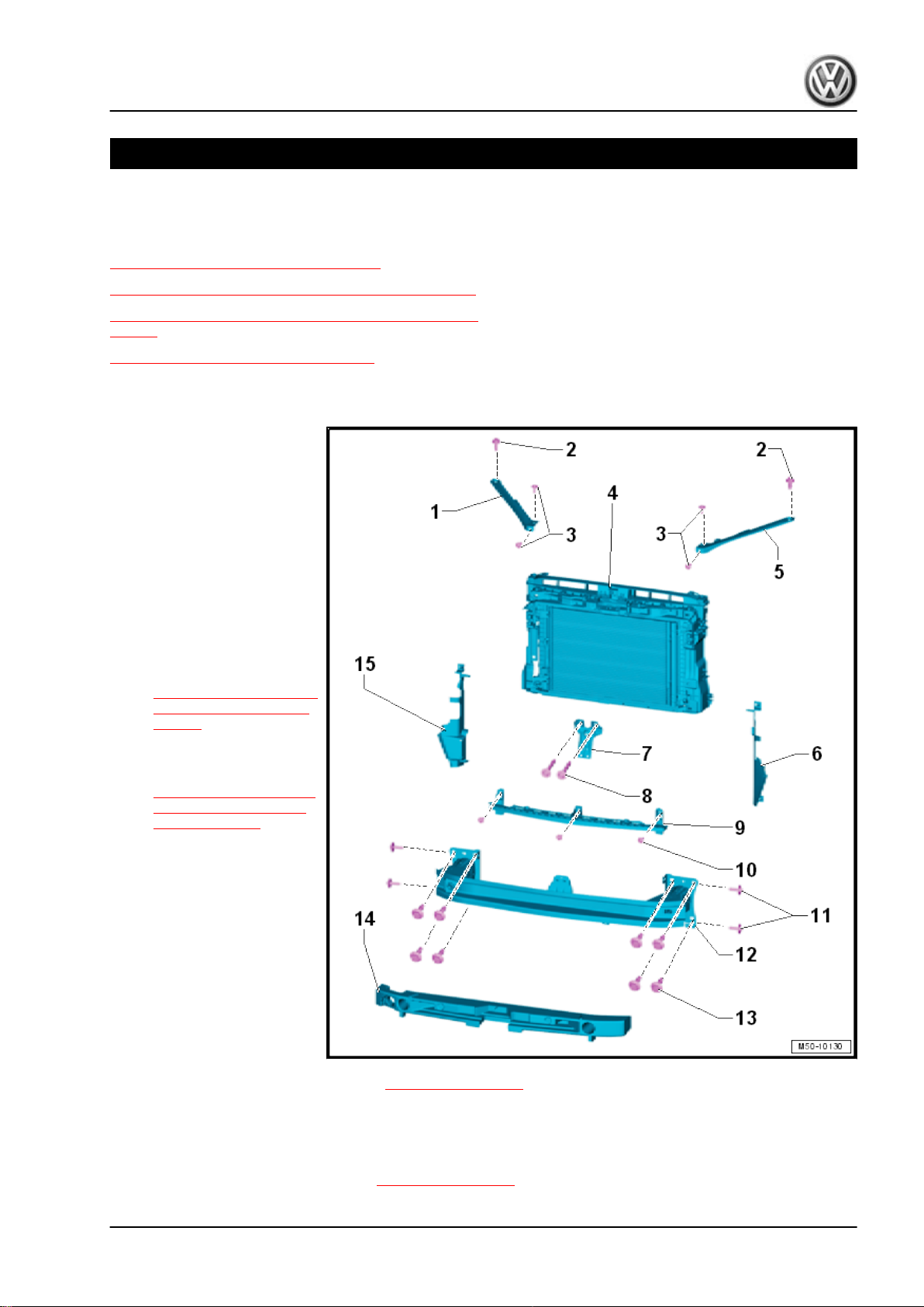
1.1 Overview - Lock Carrier
1 - Support
❑ Right
2 - Bolt
❑ 8 Nm
❑ Quantity: 1 on each side
3 - Bolt
❑ 8 Nm
❑ Quantity: 2 on each side
4 - Lock Carrier with Attach‐
ments
❑ Removing and instal‐
ling. Refer to
⇒ “1.2 Lock Carrier, Re‐
moving and Installing”,
page 2 .
❑ Service position, imple‐
menting and resetting.
Refer to
⇒ “1.3 Service Position,
Implementing and Re‐
setting”, page 4 .
5 - Support
❑ Left
6 - Air Duct
❑ Left
❑ There are different ver‐
sions. Refer to the Parts
Catalog for the alloca‐
tion.
7 - Lock Carrier Support
Golf 2015 ➤ , Golf Variant 2015 ➤
Body Exterior - Edition 02.2016
8 - Bolt
❑ Quantity: 2
❑ Tightening specification -item 13- ⇒ Item 13 (page 25) .
9 - Center Guide
10 - Bolt
❑ Quantity: 3
❑ Tightening specification -item 6- ⇒ Item 6 (page 317) .
1. Lock Carrier 1
Page 10
Golf 2015 ➤ , Golf Variant 2015 ➤
Body Exterior - Edition 02.2016
11 - Bolt
❑ Quantity: 2 on each side
❑ Tightening specification -item 2- ⇒ Item 2 (page 316) .
12 - Impact Member
❑ Overview. Refer to ⇒ “1.3 Overview - Impact Member”, page 316 .
13 - Bolt
❑ Quantity: 4 on each side
❑ Tightening specification -item 3- ⇒ Item 3 (page 316) .
14 - Foam Piece
15 - Air Duct
❑ Right
❑ There are different versions. Refer to the Parts Catalog for the allocation.
1.2 Lock Carrier, Removing and Installing
Special tools and workshop equipment required
♦ Guide Pins - T10093-
♦ Torque Wrench 1331 5-50Nm - VAG1331-
♦ Torque Wrench 1332 40-200Nm - VAG1332-
Note
♦
The lock carrier is a safety-related component. For this reason the lock carrier may only be serviced in the
specified positions.
♦
Replace the lock carrier if it is damaged.
♦
For vehicles with the Distance Regulation Control Module - J428- , the Distance Regulation Control Module
- J428- must be re-aligned during every removal and installation or replacement of the lock carrier.
♦
Notes and work procedures for the Distance Regulation Control Module - J428- . Refer to ⇒ Electrical
Equipment; Rep. Gr. 27 ; Adaptive Cruise Control .
2 Rep. Gr.50 - Body Front
Page 11
Golf 2015 ➤ , Golf Variant 2015 ➤
Body Exterior - Edition 02.2016
Removing
– Only perform the service position using the Guide Pins -
T10093- . Refer to
⇒ “1.3 Service Position, Implementing and Resetting”,
page 4 .
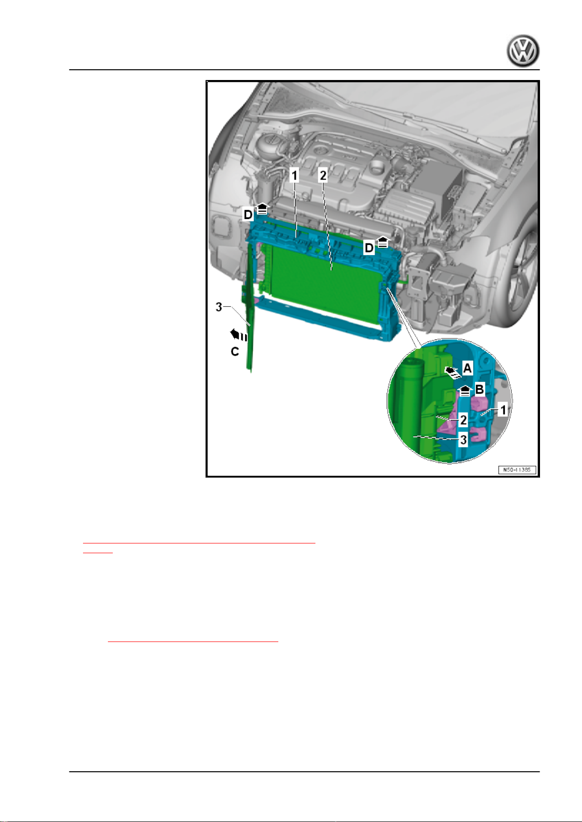
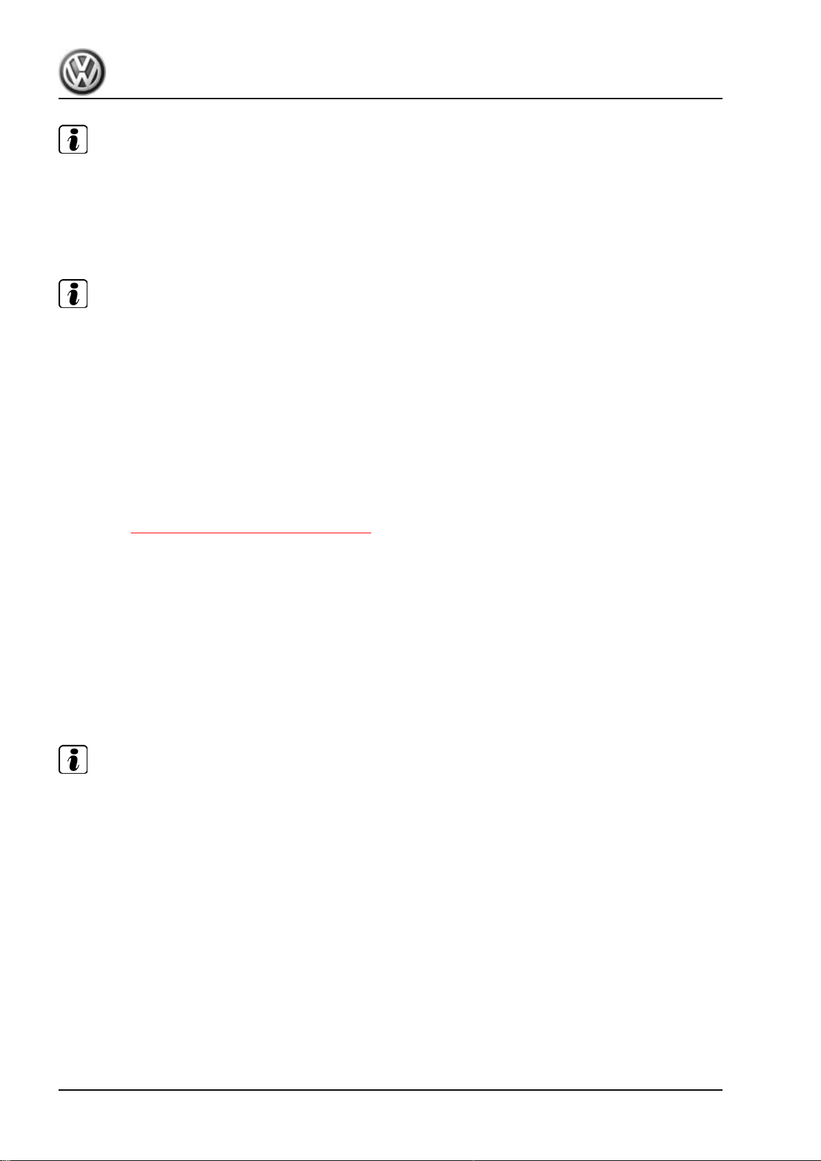
– Disconnect the connector to the lock carrier -1-.
– Together with a second technician, remove the Guide Pins -
T10093- on the left and right longitudinal member. Support the
lock carrier with the attachments -1-. For example on the Scis‐
sor Lift Table - VAS6131B- .
– Remove the bumper carrier and the left and right support. Re‐
fer to ⇒ “1.1 Overview - Lock Carrier”, page 1 .
– Loosen the radiator from the lock carrier -arrow A-, but do not
remove. Refer to ⇒ Rep. Gr. 19 ; Radiator/Coolant Fan .
– Lift the condenser -3- off of the radiator module -2- -arrow B-
and pivot it slightly out of the lock carrier -arrow C-, but do not
remove.
– Remove the lock carrier -1- between the radiator and con‐
denser upward -D arrows-.
Page 12
Golf 2015 ➤ , Golf Variant 2015 ➤
Body Exterior - Edition 02.2016
Note
♦
Never hang the condenser and the hydraulic fluid cooler on the lines.
♦
The lines for the condenser and hydraulics must not be kinked.
Installing
Install in reverse order of removal. Note the following:
Note
♦
Always install the lock carrier onto the attaching points at the
frontmost positions of the oblong holes. Only then can the lock
carrier slide in the event of a crash.
♦
For vehicles with the Distance Regulation Control Module J428- , the Distance Regulation Control Module - J428- must
be re-aligned when loosening, removing and installing or re‐
placing the lock carrier.
♦
Notes and work procedures for the Distance Regulation Con‐
trol Module - J428- . Refer to ⇒ Electrical Equipment; Rep.
Gr. 27 ; Adaptive Cruise Control .
Tightening Specifications
♦ Refer to ⇒ “1.1 Overview - Lock Carrier”, page 1
1.3 Service Position, Implementing and Re‐
setting
Special tools and workshop equipment required
♦ Guide Pins - T10093-
♦ Adapters For Service Position - T10467-
♦ Torque Wrench 1331 5-50Nm - VAG1331-
♦ Torque Wrench 1332 40-200Nm - VAG1332-
Moving into Service Position
Note
♦
The lock carrier is a safety-related component. For this reason the lock carrier may not be serviced.
♦
Replace the lock carrier if it is damaged.
♦
For vehicles with the Distance Regulation Control Module - J428- , the Distance Regulation Control Module
- J428- must be re-aligned during every removal and installation or replacement of the lock carrier.
♦
Notes and work procedures for the Distance Regulation Control Module - J428- . Refer to ⇒ Electrical
Equipment; Rep. Gr. 27 ; Adaptive Cruise Control .
4 Rep. Gr.50 - Body Front
Page 13
Golf 2015 ➤ , Golf Variant 2015 ➤
Body Exterior - Edition 02.2016
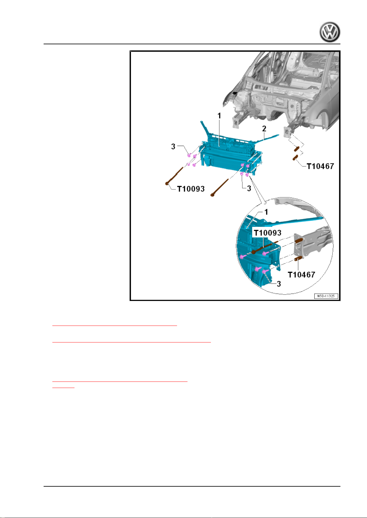
– Remove the noise insulation. Refer to
⇒ “4.1 Overview - Noise Insulation”, page 422 .
– Remove the front bumper cover. Refer to
⇒ “1.5 Bumper Cover, Removing and Installing”, page 317 .
– Remove the headlamps. Refer to ⇒ Electrical Equipment;
Rep. Gr. 94 ; Headlamp; Headlamp, Removing and Installing .
– Remove the release cable from the trunk lid actuation bracket.
Refer to
⇒ “1.14 Release Cable, Removing and Installing”,
page 45 .
– Disengage the washer fluid reservoir filler tube from the sup‐
port -2-. Refer to ⇒ Electrical Equipment; Rep. Gr. 92 ;
Windshield Washer System; Washer Fluid Reservoir, Remov‐
ing and Installing .
– Remove only one bolt -3- from the left and right longitudinal
members.
– Instead of the bolts, install the Guide Pins - T10093- into the
holes in the left and right longitudinal member.
– Remove the remaining bolts -3- from the left and right longi‐
tudinal members.
– The lock carrier with the attachments -1- can be pulled forward
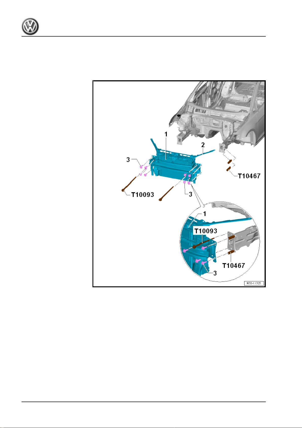
approximately 10 cm on the Guide Pins - T10093- . Be careful
1. Lock Carrier 5
Page 14
Golf 2015 ➤ , Golf Variant 2015 ➤
Body Exterior - Edition 02.2016
of the wires on the lock carrier. Disconnect the connectors if
necessary.
– Install the Adapters For Service Position - T10467- (quantity:
2 on each side) on the left and right side between the bumper
carrier and the longitudinal member.
Service Position, Resetting
– Remove the Adapters For Service Position - T10467- on the
left and right side between the bumper carrier and longitudinal
member.
– Push the lock carrier with the attachments -1- onto the Guide
Pins - T10093- on the longitudinal members.
– Insert the left and right bolts -3-.
– Remove the left and right Guide Pins - T10093- .
– Align the lock carrier with the attachments -1- on the longitu‐
dinal members and between the fenders. Refer to ⇒ Body
Repair; Rep. Gr. 00 ; Body Gap Dimensions; Front Body .
6 Rep. Gr.50 - Body Front
Page 15
Golf 2015 ➤ , Golf Variant 2015 ➤
Body Exterior - Edition 02.2016
Note
♦
Always install the lock carrier onto the attaching points at the frontmost positions of the oblong holes. Only
then can the lock carrier slide in the event of a crash.
♦
For vehicles with the Distance Regulation Control Module - J428- , the Distance Regulation Control Module
- J428- must be re-aligned when loosening, removing and installing or replacing the lock carrier.
♦
Notes and work procedures for the Distance Regulation Control Module - J428- . Refer to ⇒ Electrical
Equipment; Rep. Gr. 27 ; Adaptive Cruise Control .
Continue to install in the reverse of removal. Note the following:
Note
♦
Make sure that the charge air cooler pressure hoses are re-installed correctly.
♦
The hoses and lines must not be pinched.
– Adjust the headlamps. Refer to ⇒ Electrical Equipment; Rep.
Gr. 94 ; Headlamp; Headlamp, Adjusting .
Tightening Specifications
1.4 Lock Carrier, Servicing
⇒ “1.4.1 Left Headlamp Mount”, page 7
⇒ “1.4.2 Right Headlamp Mount”, page 9
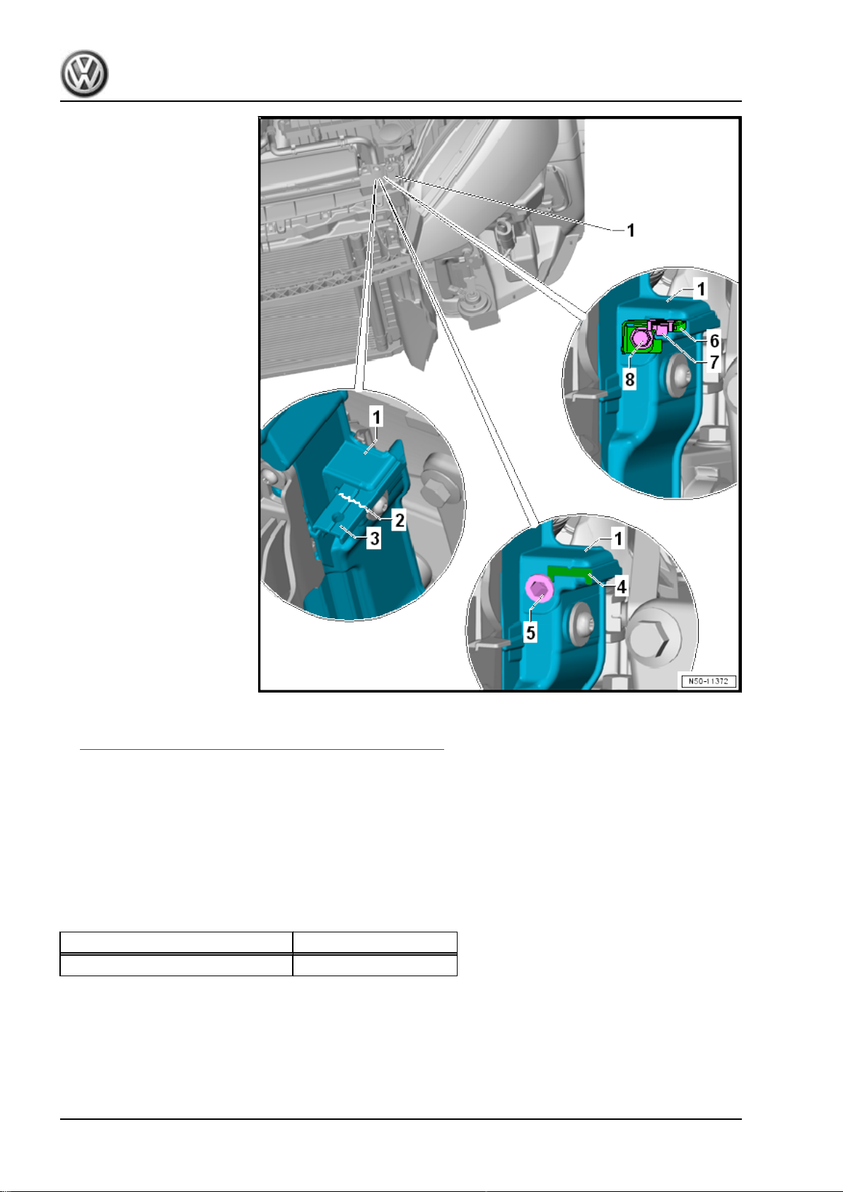
1.4.1 Left Headlamp Mount
Note
The line -2- shows a possible crack.
1. Lock Carrier 7
Page 16
Golf 2015 ➤ , Golf Variant 2015 ➤
Body Exterior - Edition 02.2016
– Remove the front bumper cover. Refer to
⇒ “1.5 Bumper Cover, Removing and Installing”, page 317 .
– Remove the headlamps. Refer to ⇒ Electrical Equipment;
Rep. Gr. 94 ; Headlamp; Headlamp, Removing and Installing .
– Cut or saw the headlamp mount -4- evenly off the lock carrier
-1-.
– Position the rivet -5-.
– Position the new bracket -6- with the spring nut -7-.
– Tighten the bolt -8-.
Tightening Specifications
Component Tightening Specification
Lock carrier bracket 5 Nm
8 Rep. Gr.50 - Body Front
Page 17
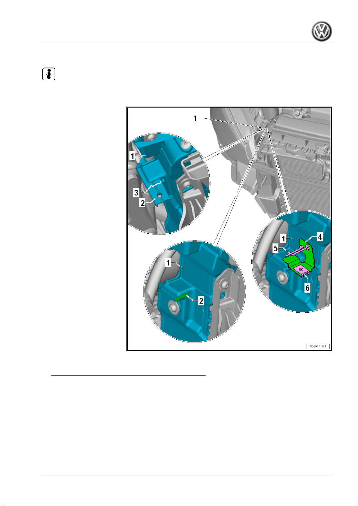
1.4.2 Right Headlamp Mount
Note
The line -3- shows a possible crack.
Golf 2015 ➤ , Golf Variant 2015 ➤
Body Exterior - Edition 02.2016
– Remove the front bumper cover. Refer to
⇒ “1.5 Bumper Cover, Removing and Installing”, page 317 .
– Remove the headlamps. Refer to ⇒ Electrical Equipment;
Rep. Gr. 94 ; Headlamp; Headlamp, Removing and Installing .
– Cut or saw the headlamp mount -2- evenly off the lock carrier
-1-.
– Install the new bracket -4- with the spring nut -6-.
– Install the pop rivets -5-.
1. Lock Carrier 9
Page 18
Golf 2015 ➤ , Golf Variant 2015 ➤
Body Exterior - Edition 02.2016
2 Fender
⇒ “2.1 Overview - Fender”, page 10
⇒ “2.2 Overview - Deformation Element”, page 11
⇒ “2.3 Fender, Removing and Installing”, page 11
⇒ “2.4 Fender Brace, Removing and Installing”, page 14
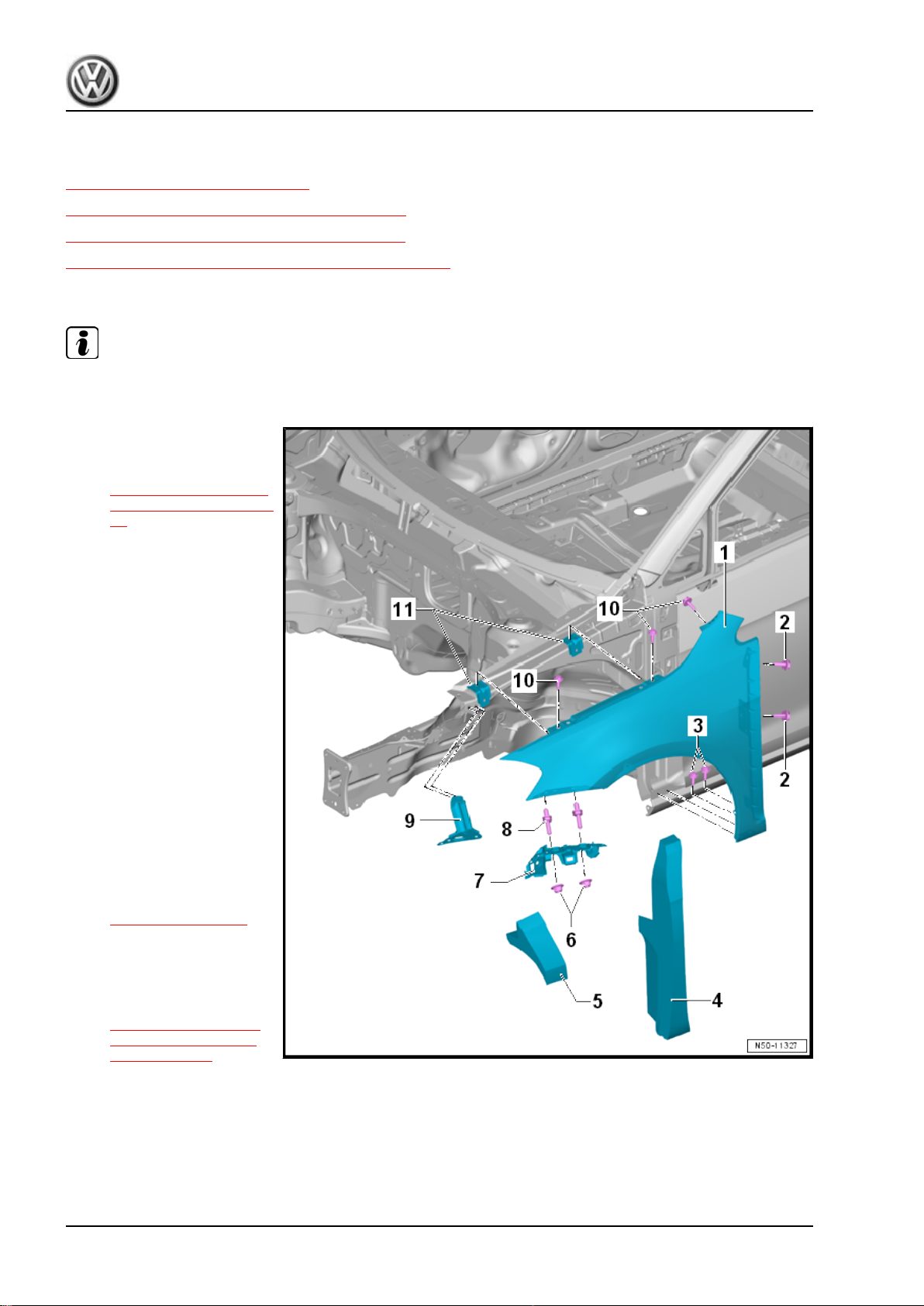
2.1 Overview - Fender
Note
The illustration shows the left side. The right side is identical.
1 - Fender
❑ Removing and instal‐
ling. Refer to
⇒ “2.3 Fender, Remov‐
ing and Installing”, page
11 .
2 - Bolt
❑ 6 Nm
❑ Quantity: 2, A-pillar
3 - Bolt
❑ 6 Nm
❑ Quantity: 2, side sill
4 - Brace Insulation
❑ Inserted between the
fender and A-pillar.
5 - Fender Insulation
❑ Inserted between the
fender and the upper
wheel housing longitudi‐
nal member.
6 - Hex Nut
❑ Quantity: 2
❑ Tightening specification
-item 3-
⇒ Item 3 (page 317) .
7 - Guide
❑ Removing:
– Remove the front bump‐
er cover. Refer to
⇒ “1.5 Bumper Cover,
Removing and Instal‐
ling”, page 317 .
– Remove the hex nut -6-.
❑ There are different versions. Refer to the Parts Catalog for the allocation.
8 - Double Bolt
❑ 6 Nm
❑ Fender brace, quantity 2
10 Rep. Gr.50 - Body Front
Page 19
Golf 2015 ➤ , Golf Variant 2015 ➤
Body Exterior - Edition 02.2016
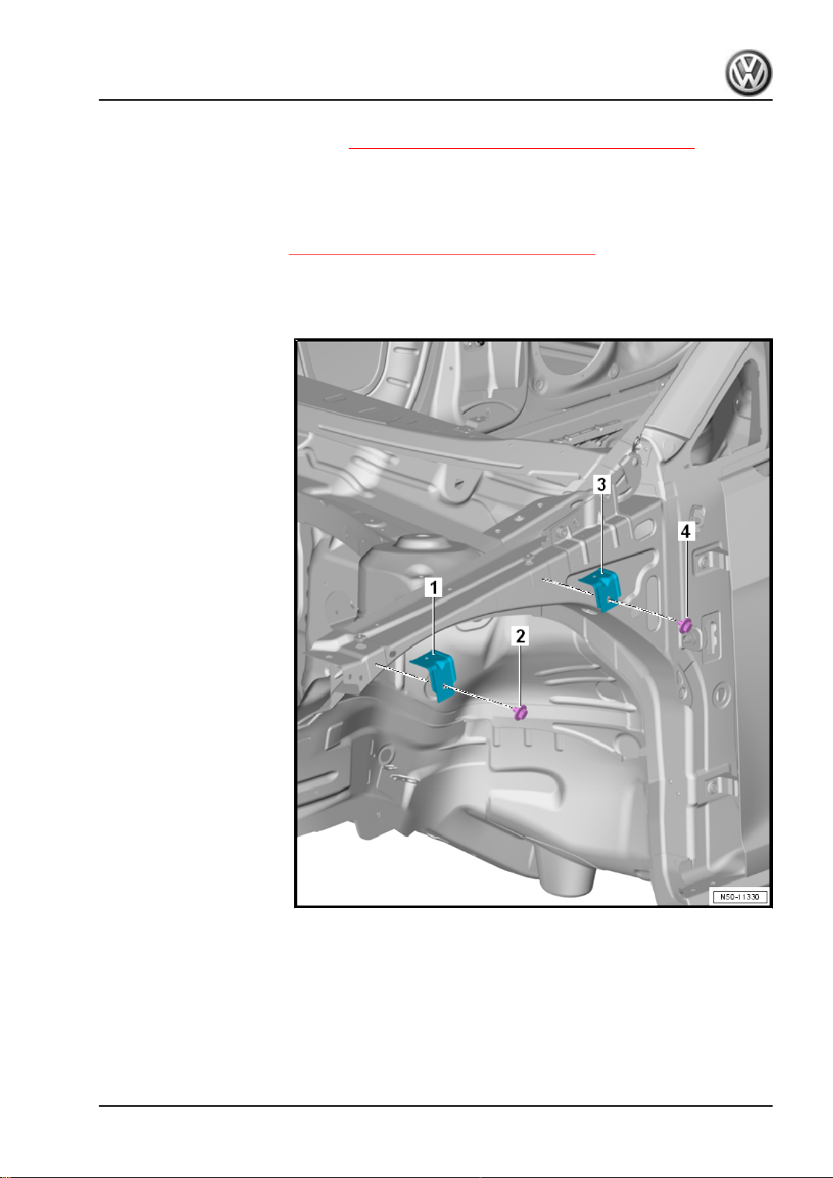
9 - Fender Brace
❑ Removing and installing. Refer to ⇒ “2.4 Fender Brace, Removing and Installing”, page 14 .
10 - Bolt
❑ 6 Nm
❑ Fender connecting piece, quantity 3
11 - Deformation Element
❑ Front and rear. Refer to ⇒ “2.2 Overview - Deformation Element”, page 11 .
2.2 Overview - Deformation Element
1 - Front Deformation Element
2 - Bolt
❑ 6 Nm
3 - Rear Deformation Element
4 - Bolt
❑ 6 Nm
2.3 Fender, Removing and Installing
Special tools and workshop equipment required
♦ Torque Wrench 1783 - 2-10Nm - VAG1783-
2. Fender 11
Page 20
Golf 2015 ➤ , Golf Variant 2015 ➤
Body Exterior - Edition 02.2016
Note
The following describes the removal and installation of the left fender. Removing and installing the right fender
is identical.
Removing
– Remove the front wheel housing liner. Refer to
⇒ “8.4 Front Wheel Housing Liner, Removing and Installing”,
page 447 .
– Remove the front bumper cover. Refer to
⇒ “1.5 Bumper Cover, Removing and Installing”, page 317 .
– Remove the headlamps. Refer to ⇒ Electrical Equipment;
Rep. Gr. 94 ; Headlamp; Headlamp, Removing and Installing .
– Remove the left plenum chamber cover. Refer to
⇒ “3.4 Plenum Chamber Cover, Removing and Installing”,
page 19 .
– Remove the drip rail. Refer to
⇒ “3.4 Drip Rail, Removing and Installing”, page 409 .
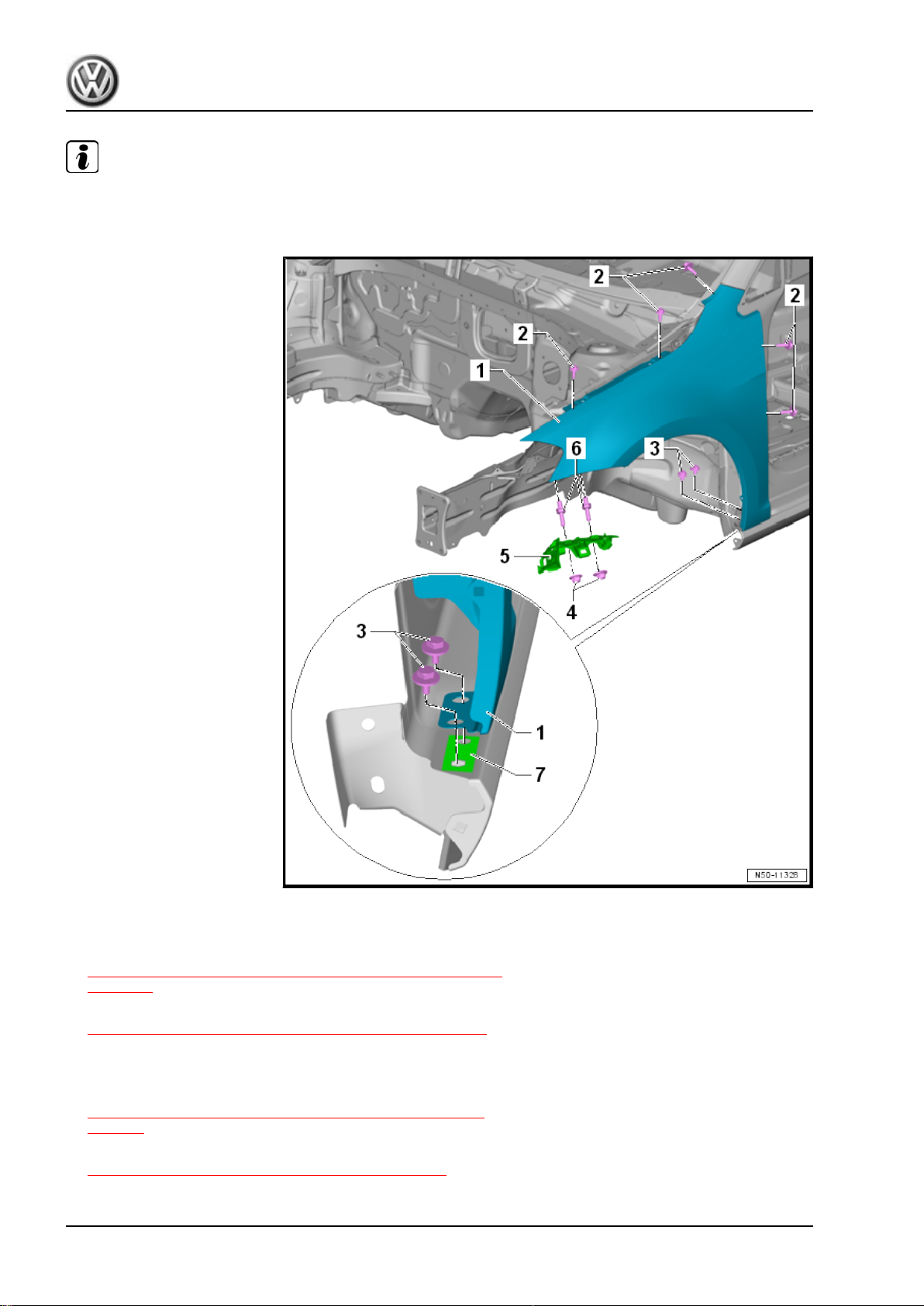
– Remove the hex nut -4- and then remove the guide -5-.
12 Rep. Gr.50 - Body Front
Page 21
Golf 2015 ➤ , Golf Variant 2015 ➤
Body Exterior - Edition 02.2016
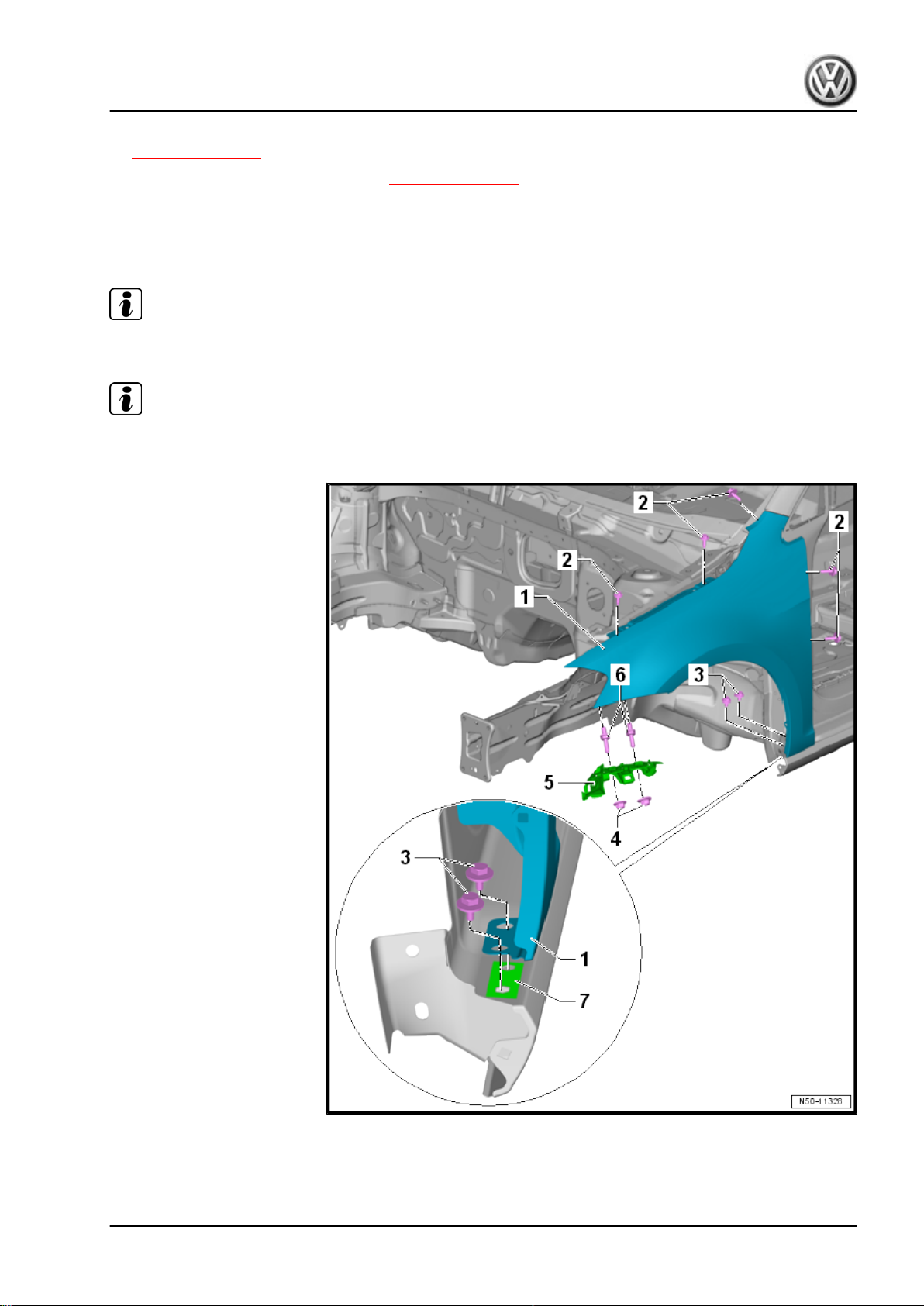
– Remove the fender noise insulation -item 5-
⇒ Item 5 (page 10) .
– Remove the brace insulation -item 4- ⇒ Item 4 (page 10) .
– Remove the double bolts -6-.
– Remove the bolts -2 and 3-.
– Carefully remove the fender -1-.
Note
The Zinc Spacer - AKL 381 035 50- -7- (if present) will be damaged during the removal.
Note
Install the fender -1- so that it is free of tension.
Installing
Install in reverse order of removal. Note the following:
2. Fender 13
Page 22
Golf 2015 ➤ , Golf Variant 2015 ➤
Body Exterior - Edition 02.2016
– With the fender brace loosened, align the fender free of ten‐
sion. Refer to
⇒ “2.4 Fender Brace, Removing and Installing”, page 14 .
– Always insert the Zinc Spacer - AKL 381 035 50- -7- between
the fender and side sills.
– Note the parallel alignment and gap dimensions. Refer to
⇒ Body Repair; Rep. Gr. 00 ; Body Gap Dimensions; Front
Body .
Tightening Specifications
2.4 Fender Brace, Removing and Installing
Special tools and workshop equipment required
♦ Torque Wrench 1783 - 2-10Nm - VAG1783-
Note
The following describes the removal and installation of the left fender brace. Removing and installing the right
fender brace is identical.
14 Rep. Gr.50 - Body Front
Page 23
Removing
– Remove the front bumper cover. Refer to
⇒ “1.5 Bumper Cover, Removing and Installing”, page 317 .
– Remove the headlamps. Refer to ⇒ Electrical Equipment;
Rep. Gr. 94 ; Headlamp; Headlamp, Removing and Installing .
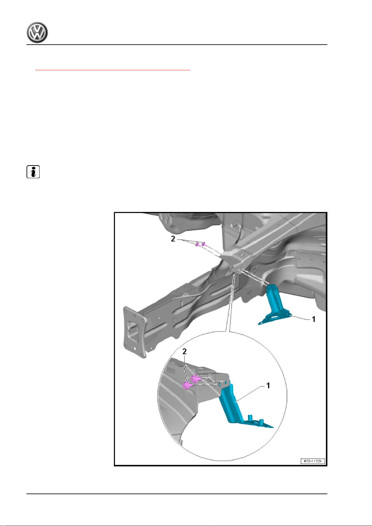
– Remove the guide for the front bumper cover -item 7-
⇒ Item 7 (page 10) .
– Remove the double bolts -item 8- ⇒ Item 8 (page 10) .
– Remove the bolts -2- and remove the fender brace -1-.
Installing
Install in reverse order of removal. Note the following:
– Adapt the fender brace and the fender to the hood and bump‐
er. Refer to ⇒ Body Repair; Rep. Gr. 00 ; Body Gap Dimen‐
sions; Front Body .
Tightening Specifications
Component Tightening Specifica‐
tions
Fender brace to the body 6 Nm
Golf 2015 ➤ , Golf Variant 2015 ➤
Body Exterior - Edition 02.2016
2. Fender 15
Page 24
Golf 2015 ➤ , Golf Variant 2015 ➤
Body Exterior - Edition 02.2016
3 Bulkhead
⇒ “3.1 Overview - Bulkhead”, page 16
⇒ “3.2 Overview - Plenum Chamber Cover”, page 17
⇒ “3.3 Bulkhead, Removing and Installing”, page 17
⇒ “3.4 Plenum Chamber Cover, Removing and Installing”,
page 19
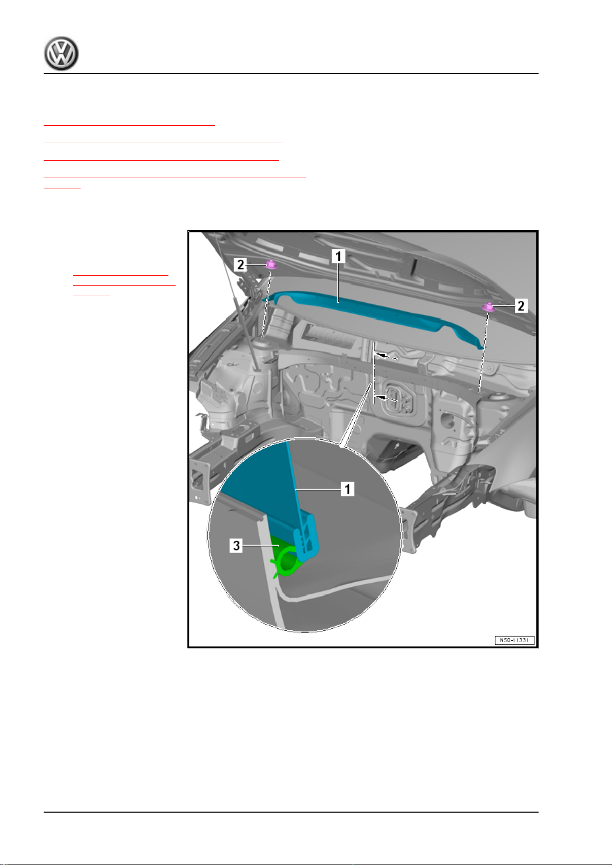
3.1 Overview - Bulkhead
1 - Bulkhead
❑ Removing and instal‐
ling. Refer to
⇒ “3.3 Bulkhead, Re‐
moving and Installing”,
page 17 .
2 - Hex Nut
❑ 8 Nm
❑ Quantity: 2
3 - Bulkhead Seal
16 Rep. Gr.50 - Body Front
Page 25
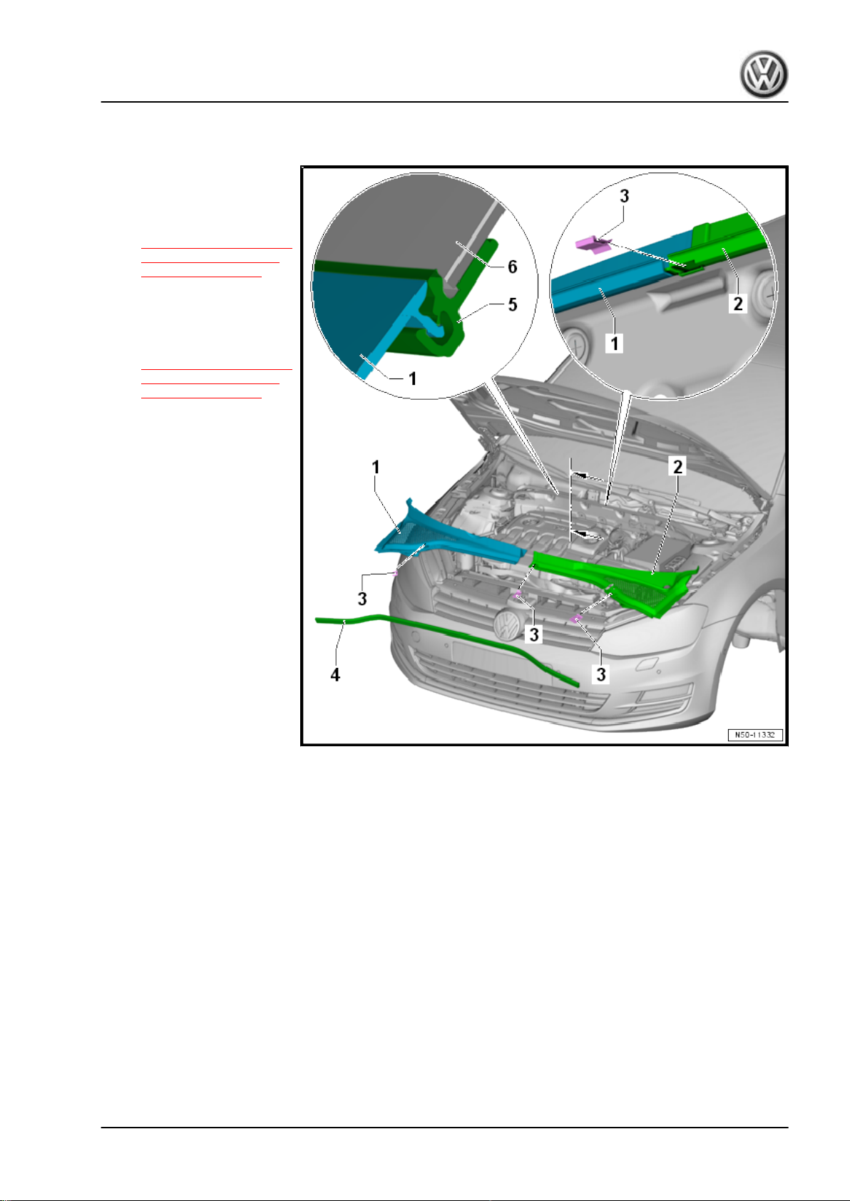
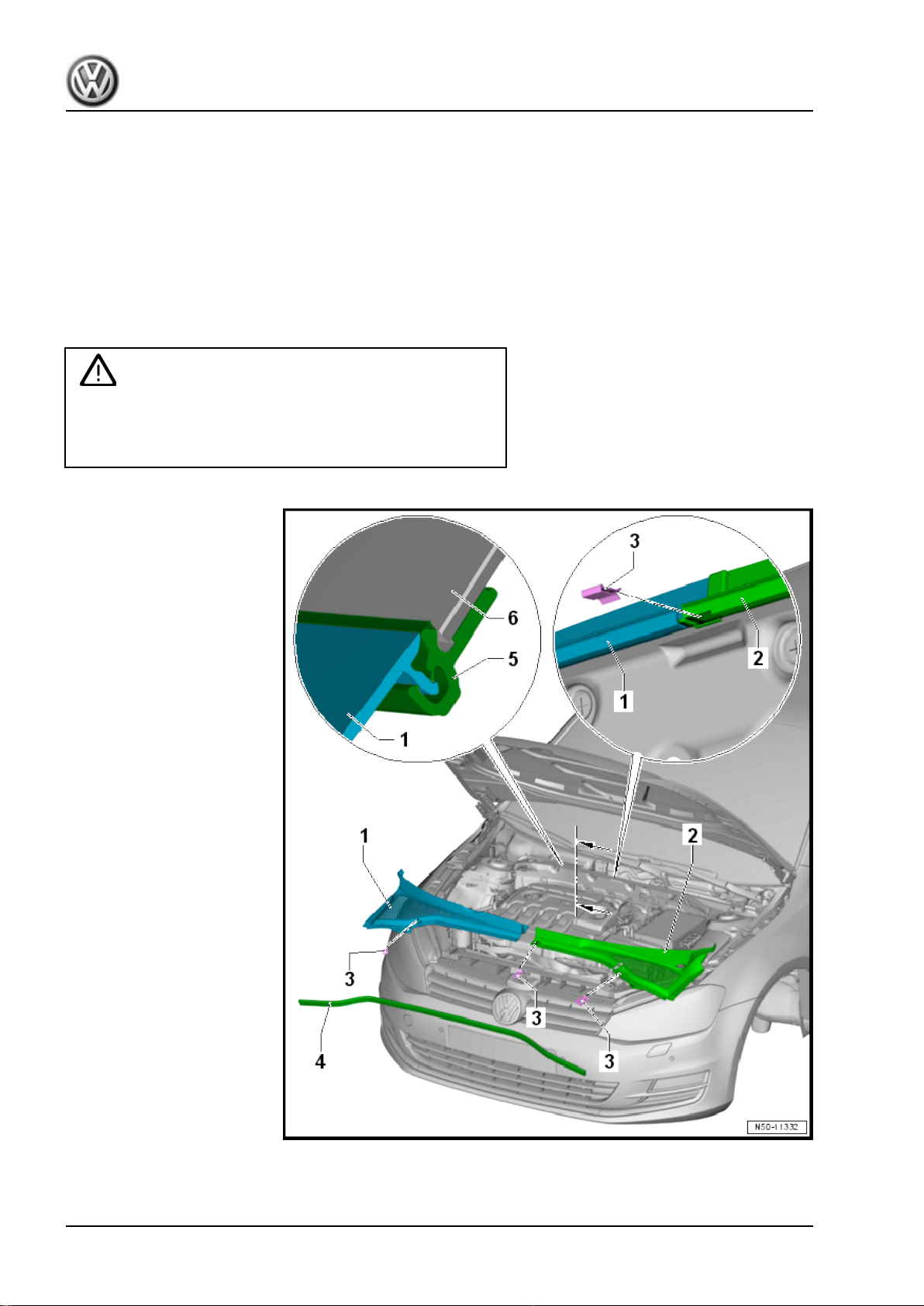
3.2 Overview - Plenum Chamber Cover
1 - Plenum Chamber Cover
❑ Right side
❑ Removing and instal‐
ling. Refer to
⇒ “3.4 Plenum Chamber
Cover, Removing and
Installing”, page 19 .
2 - Plenum Chamber Cover
❑ Left side
❑ Removing and instal‐
ling. Refer to
⇒ “3.4 Plenum Chamber
Cover, Removing and
Installing”, page 19 .
3 - Clip
❑ Quantity: 3
4 - Seal
5 - Binding Profile
❑ Windshield component
6 - Windshield
Golf 2015 ➤ , Golf Variant 2015 ➤
Body Exterior - Edition 02.2016
3.3 Bulkhead, Removing and Installing
Special tools and workshop equipment required
♦ Torque Wrench 1783 - 2-10Nm - VAG1783-
3. Bulkhead 17
Page 26
Golf 2015 ➤ , Golf Variant 2015 ➤
Body Exterior - Edition 02.2016
Removing
– Remove the plenum chamber cover. Refer to
⇒ “3.4 Plenum Chamber Cover, Removing and Installing”,
page 19 .
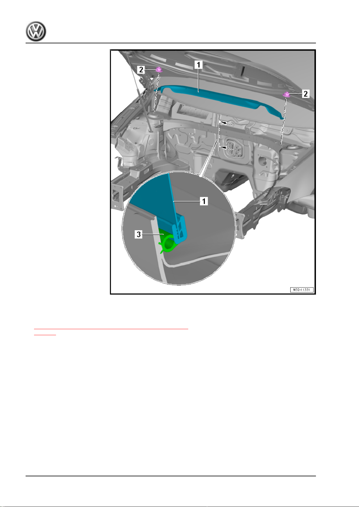
– Remove the hex nuts -2- and the bulkhead -1-.
Installing
Install in reverse order of removal.
18 Rep. Gr.50 - Body Front
Page 27
Golf 2015 ➤ , Golf Variant 2015 ➤
Body Exterior - Edition 02.2016
Tightening Specifications
3.4 Plenum Chamber Cover, Removing and Installing
Note
Removing and installing the plenum chamber cover may differ slightly depending on the model.
Removing
– Remove the wiper arms. Refer to ⇒ Electrical Equipment;
Rep. Gr. 92 ; Windshield Wiper System; Windshield Wiper
Arms, Removing and Installing .
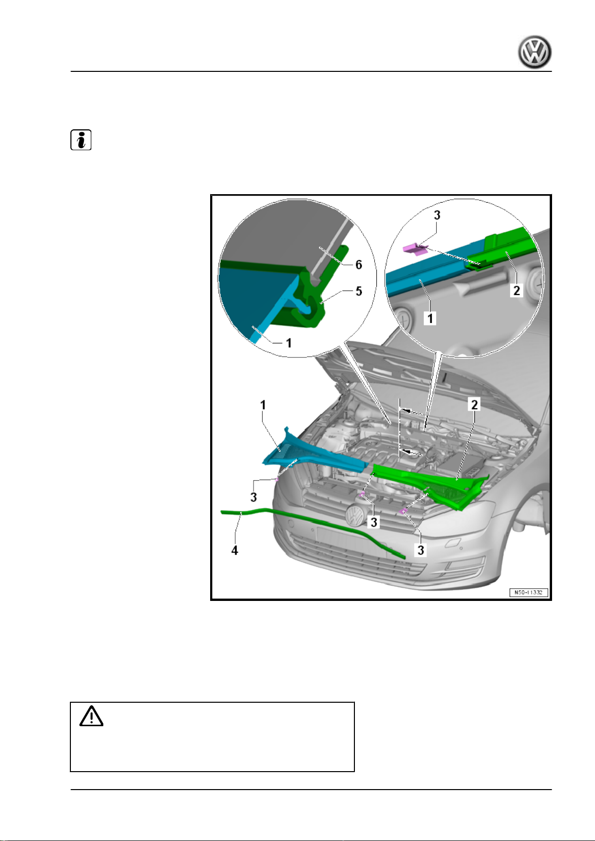
– Remove the seal -4- from the entire length of the plenum
chamber covers -1 and 2-.
Caution
The windshield -6- could break. The plenum chamber cover
must not be pried off using a levering tool (screwdriver, wedge).
The windshield will be damaged and could crack later.
3. Bulkhead 19
Page 28
Golf 2015 ➤ , Golf Variant 2015 ➤
Body Exterior - Edition 02.2016
– Unclip the clips -3- (quantity: 3).
– Starting in the center, first remove the plenum chamber cover
-2- upward out of the binding profile -5-.
– Pull the plenum chamber cover -2- forward out of the fender
and remove it.
– Then starting in the center remove the plenum chamber cover
-1- upward out of the binding profile -5-.
– Pull the plenum chamber cover -1- forward out of the fender
and remove it.
Installing
Caution
The windshield -6- could break.
Striking the plenum chamber cover to install it in the windshield
retainer can cause the windshield to crack.
20 Rep. Gr.50 - Body Front
Page 29
Golf 2015 ➤ , Golf Variant 2015 ➤
Body Exterior - Edition 02.2016
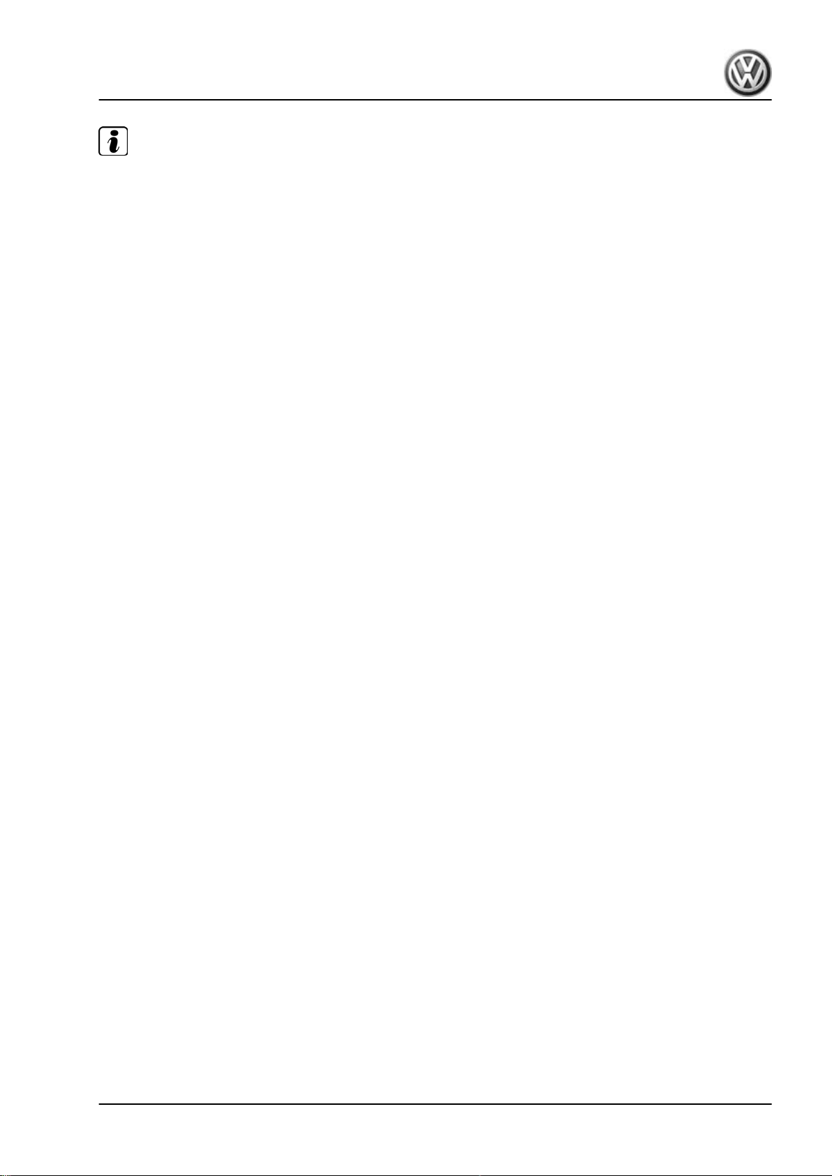
Note
♦
New windshields have an insert in the retainer. Remove this insert before installing the plenum chamber
cover.
♦
Press the plenum chamber cover into the retainer gently by hand. Do not strike it or press on it with a tool
under any circumstances.
– Spray the retainer -5- with soapy water so that the plenum
chamber covers -1 and 2- can be pressed in more easily.
– First push the plenum chamber cover -1- into the fender.
– Place the plenum chamber cover -1- on the binding profile
-5-. Starting at the outside, gently push it into the binding profile
-5-.
– Then insert the plenum chamber cover -2- into the fender.
– Place the plenum chamber cover -2- on the binding profile
-5-. Starting at the outside, gently push it into the binding profile
-5-.
– Install the clips -3- (quantity: 3).
– Attach the seal -4- to the plenum chamber covers -1 and 2-.
– Install the wiper arms. Refer to ⇒ Electrical Equipment; Rep.
Gr. 92 ; Windshield Wiper System; Windshield Wiper Arms,
Removing and Installing .
3. Bulkhead 21
Page 30
Golf 2015 ➤ , Golf Variant 2015 ➤
Body Exterior - Edition 02.2016
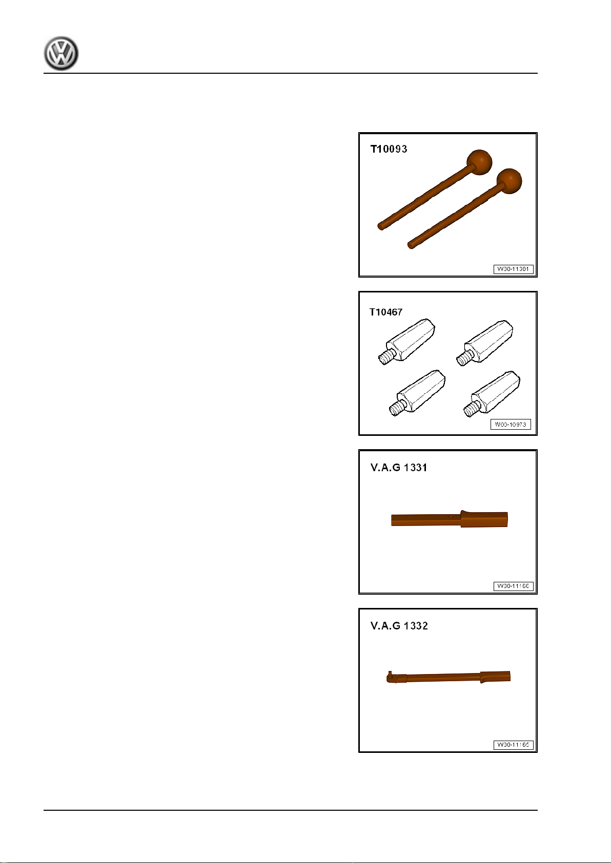
4 Special Tools
Special tools and workshop equipment required
♦ Guide Pins - T10093-
♦ Adapters For Service Position - T10467-
♦ Torque Wrench 1331 5-50Nm - VAG1331-
♦ Torque Wrench 1332 40-200Nm - VAG1332-
22 Rep. Gr.50 - Body Front
Page 31
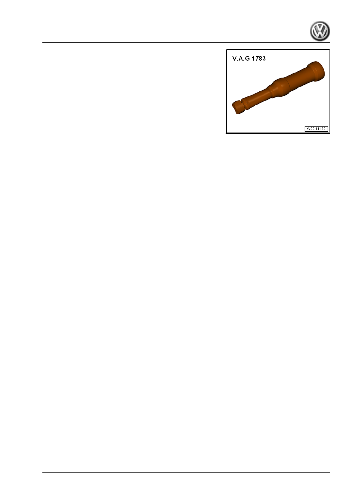
♦ Torque Wrench 1783 - 2-10Nm - VAG1783-
Golf 2015 ➤ , Golf Variant 2015 ➤
Body Exterior - Edition 02.2016
4. Special Tools 23
Page 32

Golf 2015 ➤ , Golf Variant 2015 ➤
Body Exterior - Edition 02.2016
55 – Hood, Lids
1 Hood
⇒ “1.1 Overview - Hood”, page 24
⇒ “1.2 Overview - Release Cable”, page 26
⇒ “1.3 Hood, Removing and Installing”, page 26
⇒ “1.4 Hood, Adjusting”, page 28
⇒ “1.5 Latch, Removing and Installing”, page 31
⇒ “1.6 Latch, Adjusting”, page 33
⇒ “1.7 Hood Release Lever, Removing and Installing”,
page 35
⇒ “1.8 Catch, Removing and Installing”, page 36
⇒ “1.9 Catch, Adjusting”, page 38
⇒ “1.10 Hinges, Removing and Installing”, page 39
⇒ “1.11 Insulation, Removing and Installing”, page 41
⇒ “1.12 Gas-Filled Strut, Removing and Installing”, page 44
⇒ “1.13 Gas-Filled Strut, Venting”, page 45
⇒ “1.14 Release Cable, Removing and Installing”, page 45
1.1 Overview - Hood
24 Rep. Gr.55 - Hood, Lids
Page 33
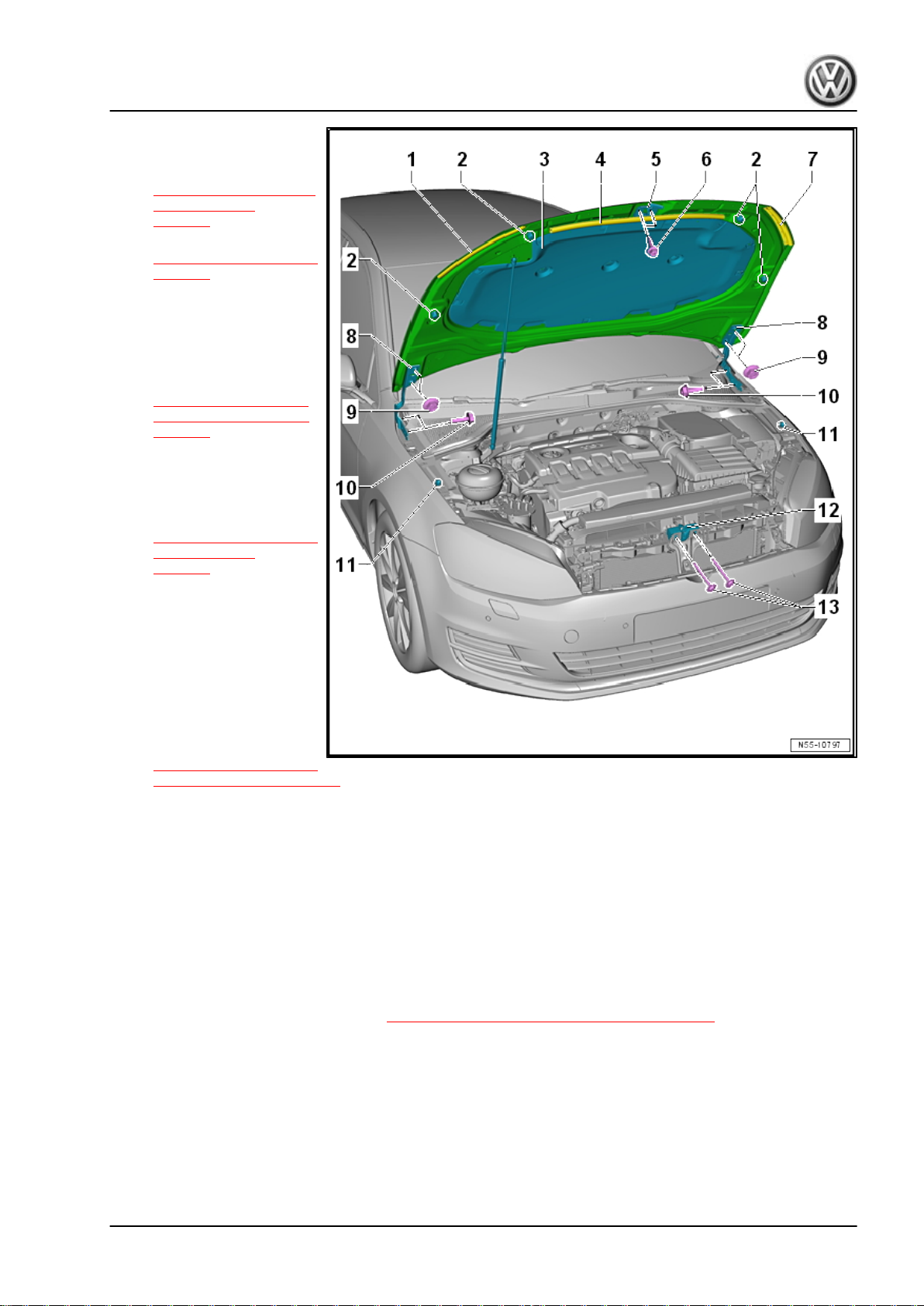
Golf 2015 ➤ , Golf Variant 2015 ➤
Body Exterior - Edition 02.2016
1 - Hood
❑ Removing and instal‐
ling. Refer to
⇒ “1.3 Hood, Removing
and Installing”,
page 26 .
❑ Adjusting. Refer to
⇒ “1.4 Hood, Adjusting”,
page 28 .
2 - Adjusting Buffer
❑ Quantity: 2
3 - Insulation
❑ Removing and instal‐
ling. Refer to
⇒ “1.11 Insulation, Re‐
moving and Installing”,
page 41 .
4 - Center Seal
5 - Catch
❑ Removing and instal‐
ling. Refer to
⇒ “1.8 Catch, Removing
and Installing”,
page 36 .
6 - Bolt
❑ 12 Nm
❑ Quantity: 2
7 - Side Seal
❑ Right and left
8 - Hinge
❑ Removing and instal‐
ling. Refer to
⇒ “1.10 Hinges, Remov‐
ing and Installing”, page 39 .
9 - Nut
❑ 22 Nm
❑ Quantity: 2 on each side
10 - Bolt
❑ 22 Nm
❑ Quantity: 2 on each side
11 - Protective Film
❑ For the adjusting buffer
12 - Latch
❑ Removing and installing. Refer to ⇒ “1.5 Latch, Removing and Installing”, page 31 .
13 - Bolt
❑ 12 Nm
❑ Quantity: 2
1. Hood 25
Page 34
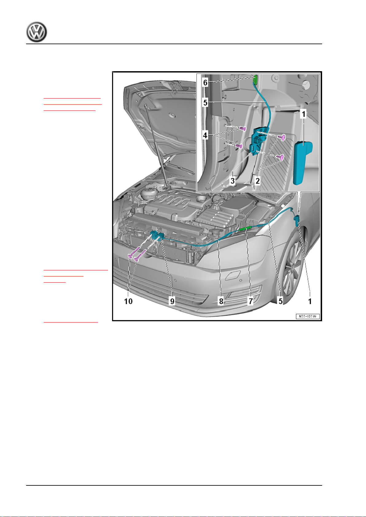
Golf 2015 ➤ , Golf Variant 2015 ➤
Body Exterior - Edition 02.2016
1.2 Overview - Release Cable
1 - Release Lever
❑ Removing and instal‐
ling. Refer to
⇒ “1.7 Hood Release
Lever, Removing and
Installing”, page 35 .
2 - Bolt
❑ 1.5 Nm
❑ Quantity: 2
3 - Bracket
4 - Expanding Nut
❑ Quantity: 2
5 - Release Cable
❑ From the bracket -3- to
the coupling -7-
6 - Grommet
7 - Coupling
8 - Release Cable
❑ From the coupling -7- to
the lid latch -9-
9 - Latch
❑ Removing and instal‐
ling. Refer to
⇒ “1.5 Latch, Removing
and Installing”,
page 31 .
10 - Bolt
❑ Quantity: 2
❑ Tightening specification
-item 13-
⇒ Item 13 (page 25) .
1.3 Hood, Removing and Installing
Special tools and workshop equipment required
♦ Torque Wrench 1331 5-50Nm - VAG1331-
26 Rep. Gr.55 - Hood, Lids
Page 35
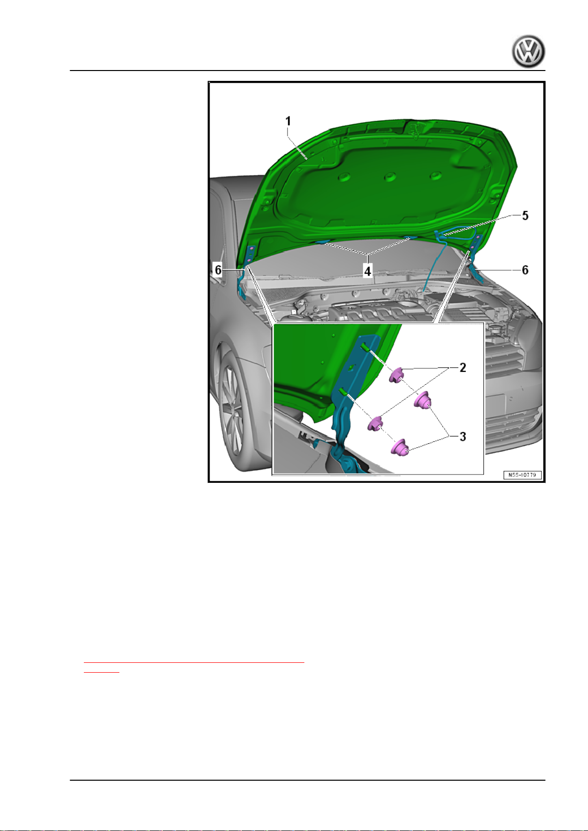
Golf 2015 ➤ , Golf Variant 2015 ➤
Body Exterior - Edition 02.2016
Removing
– Remove the spray nozzles -4-. Refer to ⇒ Electrical Equip‐
ment; Rep. Gr. 92 ; Windshield Washer System; Spray Noz‐
zles, Removing and Installing .
– Remove the line -5- from the hood opening -1-.
– If equipped, remove the caps -3-.
– Loosen the left and right hex nuts -2- from the hinge -6- (do
not remove the nuts).
A second technician is required for the rest of the removal pro‐
cedure.
– Remove the gas-filled strut. Refer to
⇒ “1.12 Gas-Filled Strut, Removing and Installing”,
page 44 .
– Remove the hex nuts -2- and lift the hood -1- out of the hinges
-6-.
1. Hood 27
Page 36
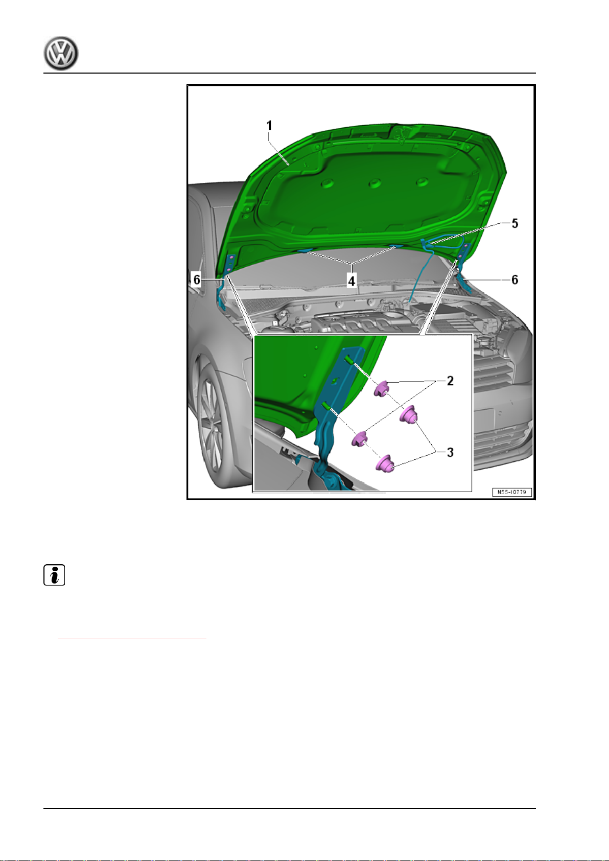
Golf 2015 ➤ , Golf Variant 2015 ➤
Body Exterior - Edition 02.2016
Installing
Install the hood -1- in reverse order of removal.
Note
Route the line -5- in a curve. If the line is installed twisted, it will kink.
– Adjust the hood -1-. Refer to
⇒ “1.4 Hood, Adjusting”, page 28 .
Tightening Specifications
1.4 Hood, Adjusting
Special tools and workshop equipment required
♦ Torque Wrench 1331 5-50Nm - VAG1331-
28 Rep. Gr.55 - Hood, Lids
Page 37
Golf 2015 ➤ , Golf Variant 2015 ➤
Body Exterior - Edition 02.2016
Note
♦
The vehicle must be on all four wheels when adjusting the hood.
♦
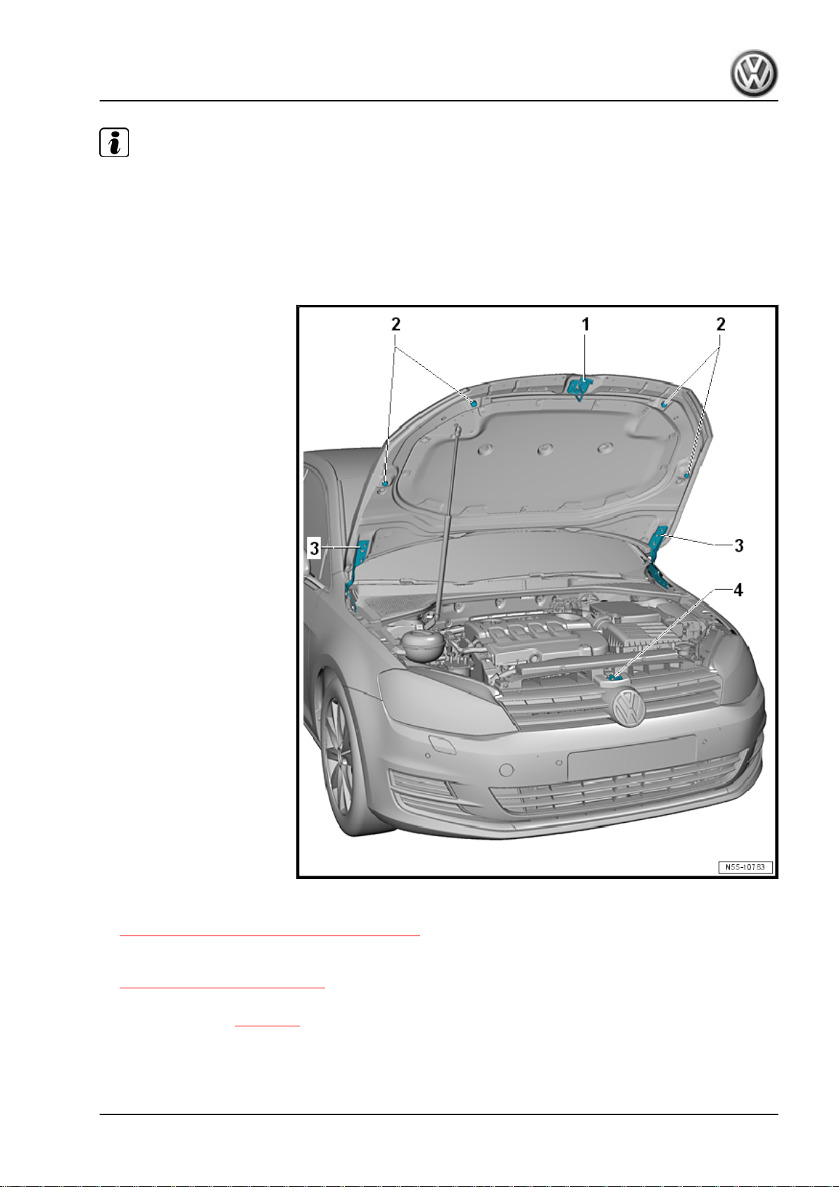
The left and right adjusting buffers -2- are not meant for adjusting. They stabilize and cushion the hood.
♦
The hood is properly adjusted when there is an overall even gap dimension when it is closed. The hood may
not be positioned too far inward or outward. The contours must also align.
♦
The hood must engage into the latch without using much force.
– Remove the catch -1-. Refer to
⇒ “1.8 Catch, Removing and Installing”, page 36 .
– The height of the front of the hood can be adjusted in relation
to the fenders using the lid lock -4-. Refer to
⇒ “1.6 Latch, Adjusting”, page 33 .
– After adjusting the hood the catch -1- can be reinstalled and
adjusted. Refer to ⇒ page 38 .
1. Hood 29
Page 38
Golf 2015 ➤ , Golf Variant 2015 ➤
Body Exterior - Edition 02.2016
Tightening Specifications
Hinges, Adjusting
Note
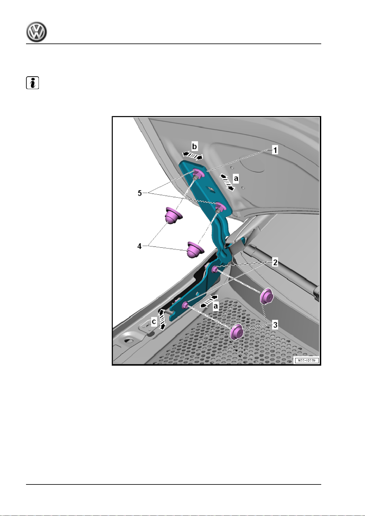
The nuts -2- and bolts -5- are not removed, just loosened.
– If equipped, remove the caps -3 or 4-.
– By loosening the hex nuts -5- on the left and right lid hinges
-1-, the hood can be adjusted from side to side in direction of
-b arrow- and lengthwise in direction of -a arrows- between the
fenders.
– By loosening the bolts -2- on the left and right lid hinges -1-,
the hood can be adjusted in height in direction of -c arrow- and
lengthwise in direction of -a arrows- between the fenders.
– Make sure the gap dimensions are even. Refer to ⇒ Body Re‐
pair; Rep. Gr. 00 ; Body Gap Dimensions; Front Body
– After adjusting, perform corrosion protection measures on the
lid hinges -1-, the hex nuts -5- and the bolts -2-.
30 Rep. Gr.55 - Hood, Lids
Page 39
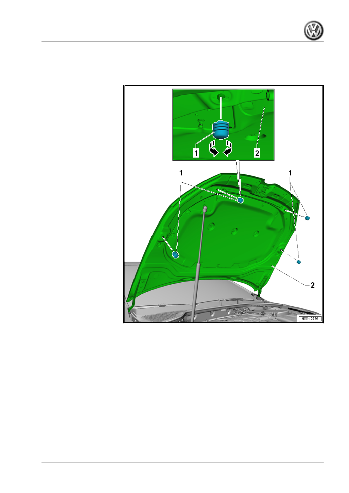
– If necessary, adjust the adjusting buffers.
Tightening Specifications
Adjusting Buffer, Adjusting
Golf 2015 ➤ , Golf Variant 2015 ➤
Body Exterior - Edition 02.2016
– Turn the adjusting buffer -1- in direction of -arrows- to adjust.
– Install and adjust the catch after adjusting the hood -2-. Refer
to ⇒ page 38 .
1.5 Latch, Removing and Installing
Special tools and workshop equipment required
♦ Torque Wrench 1331 5-50Nm - VAG1331-
1. Hood 31
Page 40
Golf 2015 ➤ , Golf Variant 2015 ➤
Body Exterior - Edition 02.2016
Removing
– Open the hood.
– Remove the release cable from the coupling. Refer to
⇒ “1.14 Release Cable, Removing and Installing”,
page 45 .
– Disconnect the connector for the hood contact switch.
Note
The connector is secured next to the right headlamp.
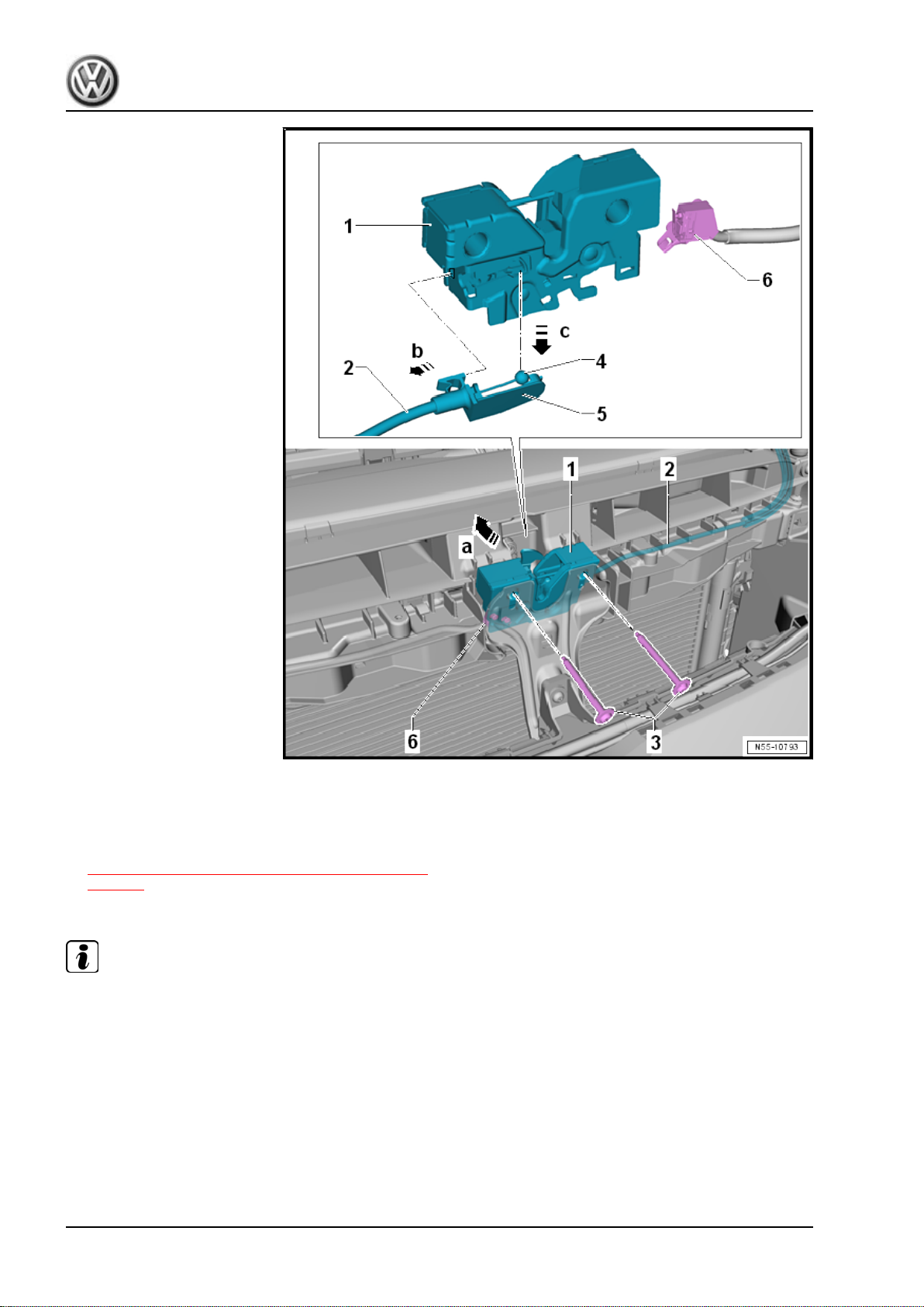
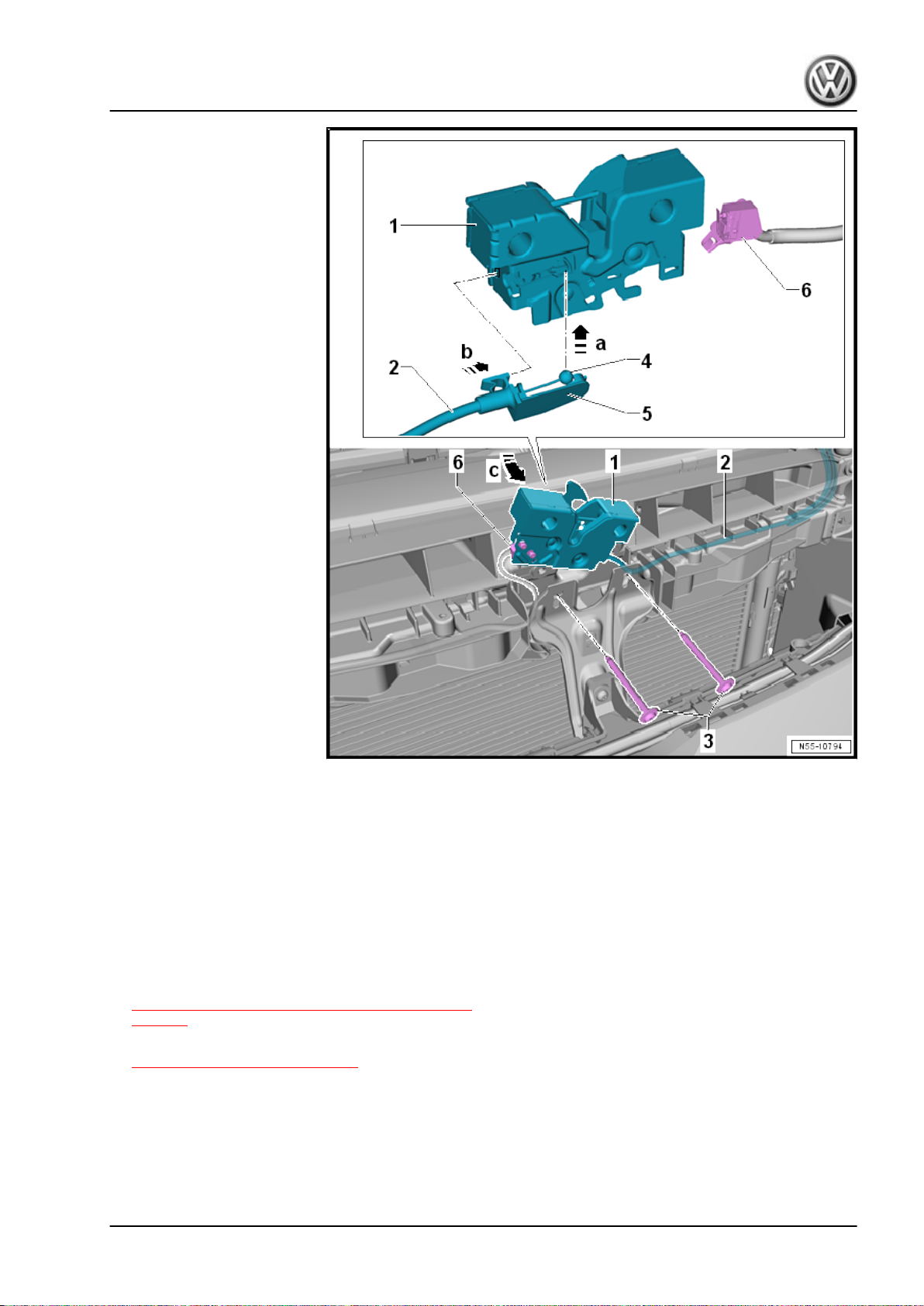
– Remove the bolts -3- from the lock carrier and remove the latch
-1- upward in direction of -arrow a-.
– Unclip the bracket -5- from the latch.
– Slightly remove the bracket -5- from the latch -1- in direction
of -arrow b- and disengage the release cable -4- in direction
of -arrow c-.
– Remove the microswitch -6- from the latch.
32 Rep. Gr.55 - Hood, Lids
Page 41
Golf 2015 ➤ , Golf Variant 2015 ➤
Body Exterior - Edition 02.2016
Installing
– Engage the release cable -4- in direction of -arrow a- and
bracket -5- in the latch -1- in direction of -arrow b-.
– Install the microswitch -6- in the latch.
– Guide the latch -1- into the lock carrier in direction of
-arrow c-.
– Install the bolts -3-.
– Connect the connector for the hood contact switch -6-.
– Connect the release cable to the coupling. Refer to
⇒ “1.14 Release Cable, Removing and Installing”,
page 45 .
– Adjust the latch. Refer to
⇒ “1.6 Latch, Adjusting”, page 33 .
– Before closing the hood, make sure the hood release lever and
the release cable are working correctly.
Tightening Specifications
1.6 Latch, Adjusting
Special tools and workshop equipment required
1. Hood 33
Page 42
Golf 2015 ➤ , Golf Variant 2015 ➤
Body Exterior - Edition 02.2016
♦ Gauge - Gap Adjustment - 3371-
♦ Torque Wrench 1331 5-50Nm - VAG1331-
Note
Use new bolts to adjust the latch.
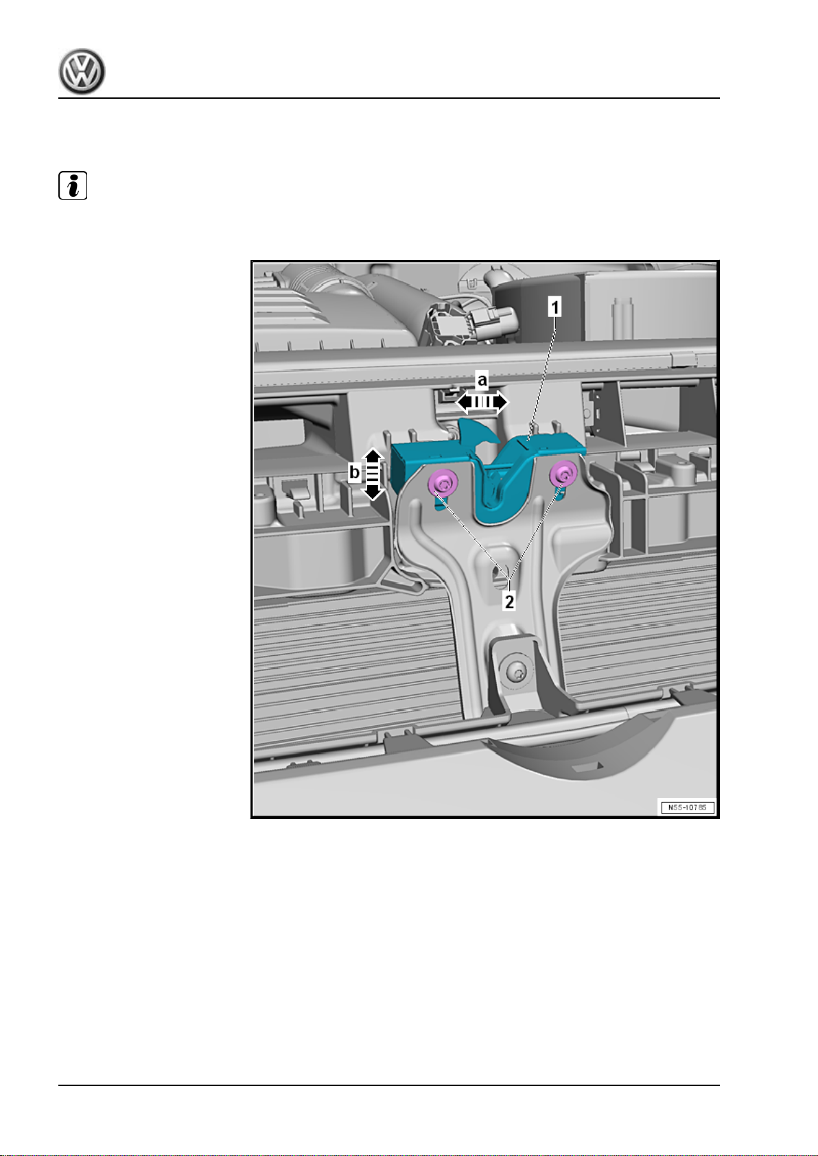
– If the bolts -2- are loosened, the latch -1- can be adjusted lat‐
erally to the hood in direction of -arrow a- and in height in
direction of -b arrow-. Refer to ⇒ Body Repair; Rep. Gr. 00 ;
Body Gap Dimensions; Front Body .
34 Rep. Gr.55 - Hood, Lids
Page 43
Golf 2015 ➤ , Golf Variant 2015 ➤
Body Exterior - Edition 02.2016
Tightening Specifications
1.7 Hood Release Lever, Removing and Installing
Removing
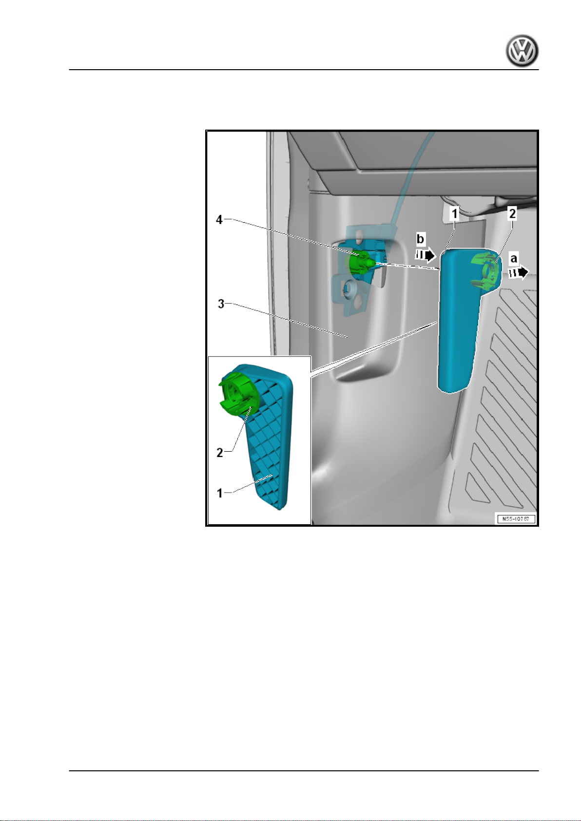
– Pull the release lever -1- and release the hood.
– Insert a small screwdriver into the gap between the release
lever -1- and the clip -2-.
– Pry the clip -2- out of the hood release lever -1- in direction of
-arrow a- and then remove the hood release lever from the
bracket -4- in direction of -arrow b-.
It is necessary to remove the A-pillar lower trim -3- to continue
working on the bracket -4-. Refer to ⇒ Body Interior; Rep. Gr.
70 ; Passenger Compartment Trim; A-Pillar Trim Panel, Remov‐
ing and Installing .
1. Hood 35
Page 44
Golf 2015 ➤ , Golf Variant 2015 ➤
Body Exterior - Edition 02.2016
Installing
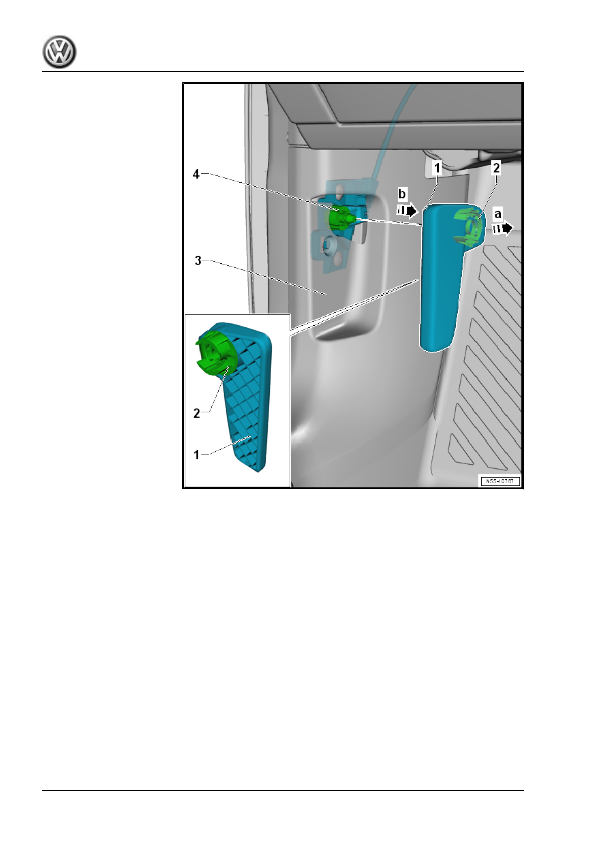
– Slide the clip -2- into the release lever -1-.
– Push the release lever -1- onto the bracket -4-.
– Before closing the hood, make sure the hood release lever and
the release cable are working correctly.
1.8 Catch, Removing and Installing
Special tools and workshop equipment required
♦ Torque Wrench 1331 5-50Nm - VAG1331-
36 Rep. Gr.55 - Hood, Lids
Page 45
Golf 2015 ➤ , Golf Variant 2015 ➤
Body Exterior - Edition 02.2016
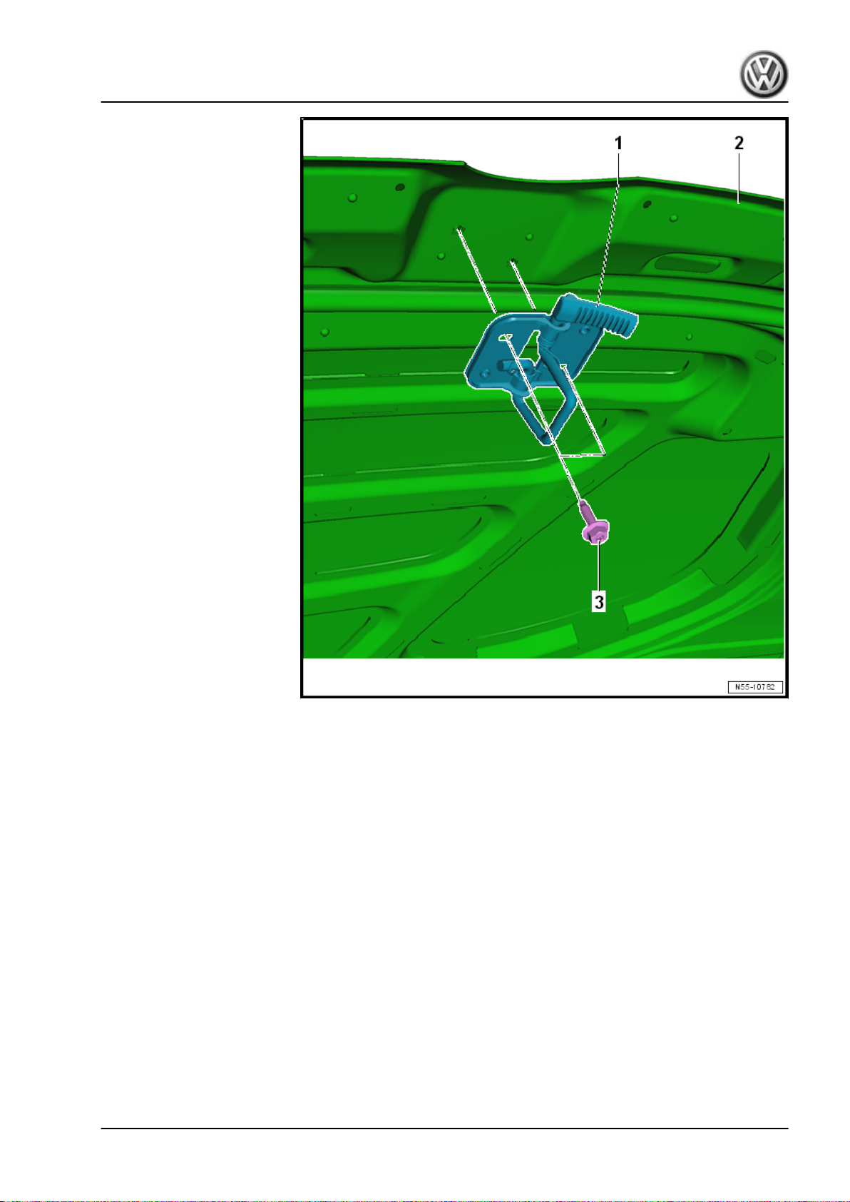
Removing
– Open the hood -2-.
– Remove the bolts -3-.
– Remove the catch -1- from the hood -2-.
1. Hood 37
Page 46
Golf 2015 ➤ , Golf Variant 2015 ➤
Body Exterior - Edition 02.2016
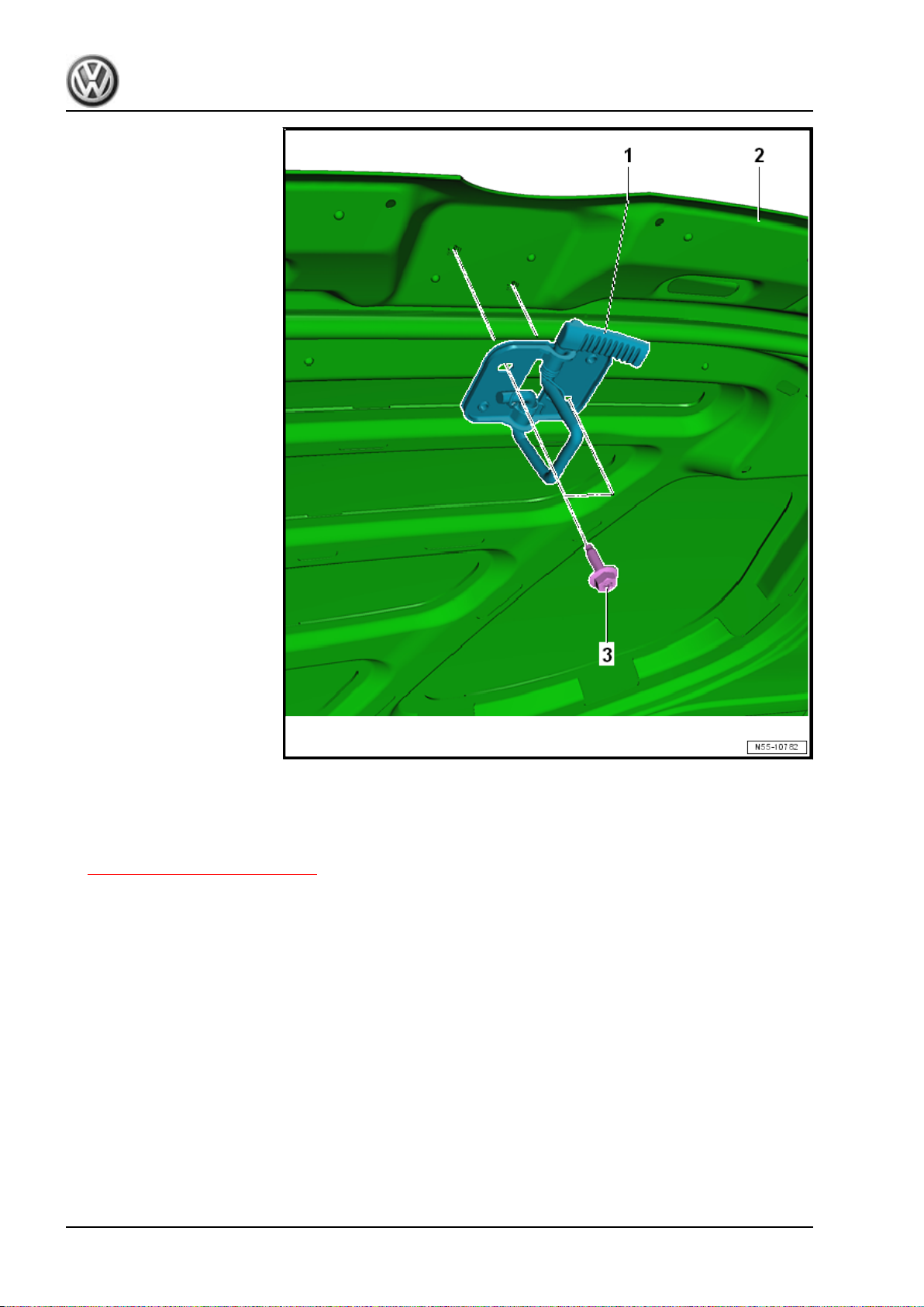
Installing
Install the catch -1- in reverse order of removal.
– Adjust the catch. Refer to
⇒ “1.9 Catch, Adjusting”, page 38 .
Tightening Specifications
1.9 Catch, Adjusting
Special tools and workshop equipment required
♦ Torque Wrench 1331 5-50Nm - VAG1331-
38 Rep. Gr.55 - Hood, Lids
Page 47
Golf 2015 ➤ , Golf Variant 2015 ➤
Body Exterior - Edition 02.2016
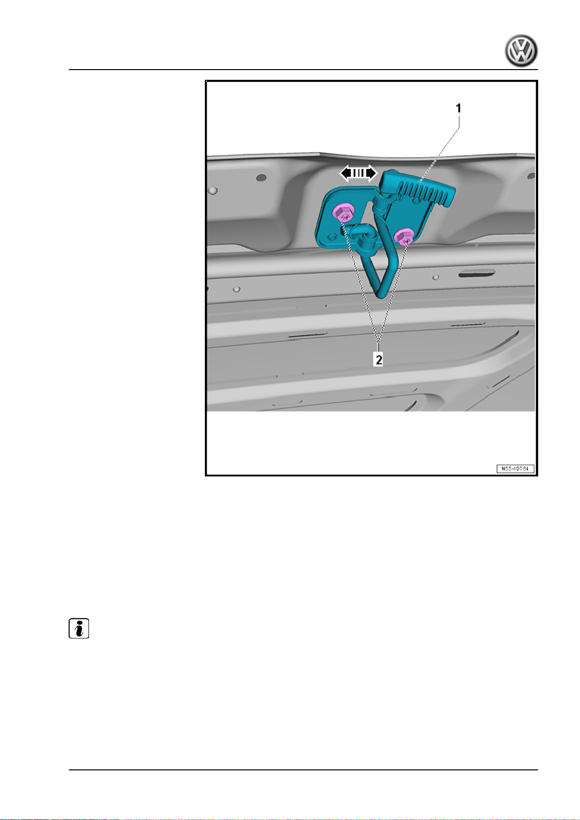
– Loosen the bolts -2-.
– Adjust the hood catch -1- on the hood -2- sideways inside the
oblong hole in direction of -arrows-.
Tightening Specifications
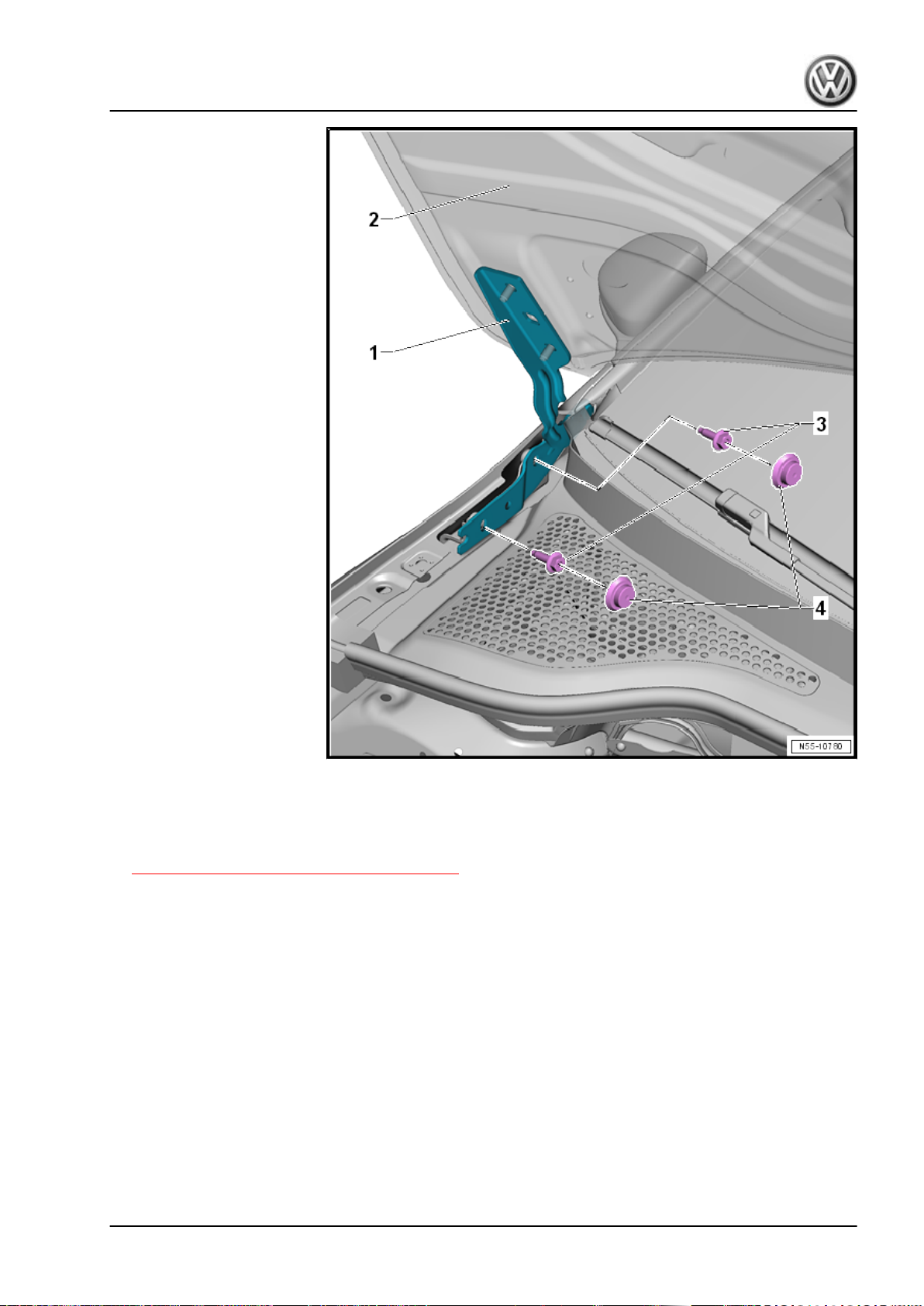
1.10 Hinges, Removing and Installing
Special tools and workshop equipment required
♦ Torque Wrench 1331 5-50Nm - VAG1331-
Note
The following describes the removal and installation of the right
hinge. Removing and installing the left hinge is identical.
1. Hood 39
Page 48
Golf 2015 ➤ , Golf Variant 2015 ➤
Body Exterior - Edition 02.2016
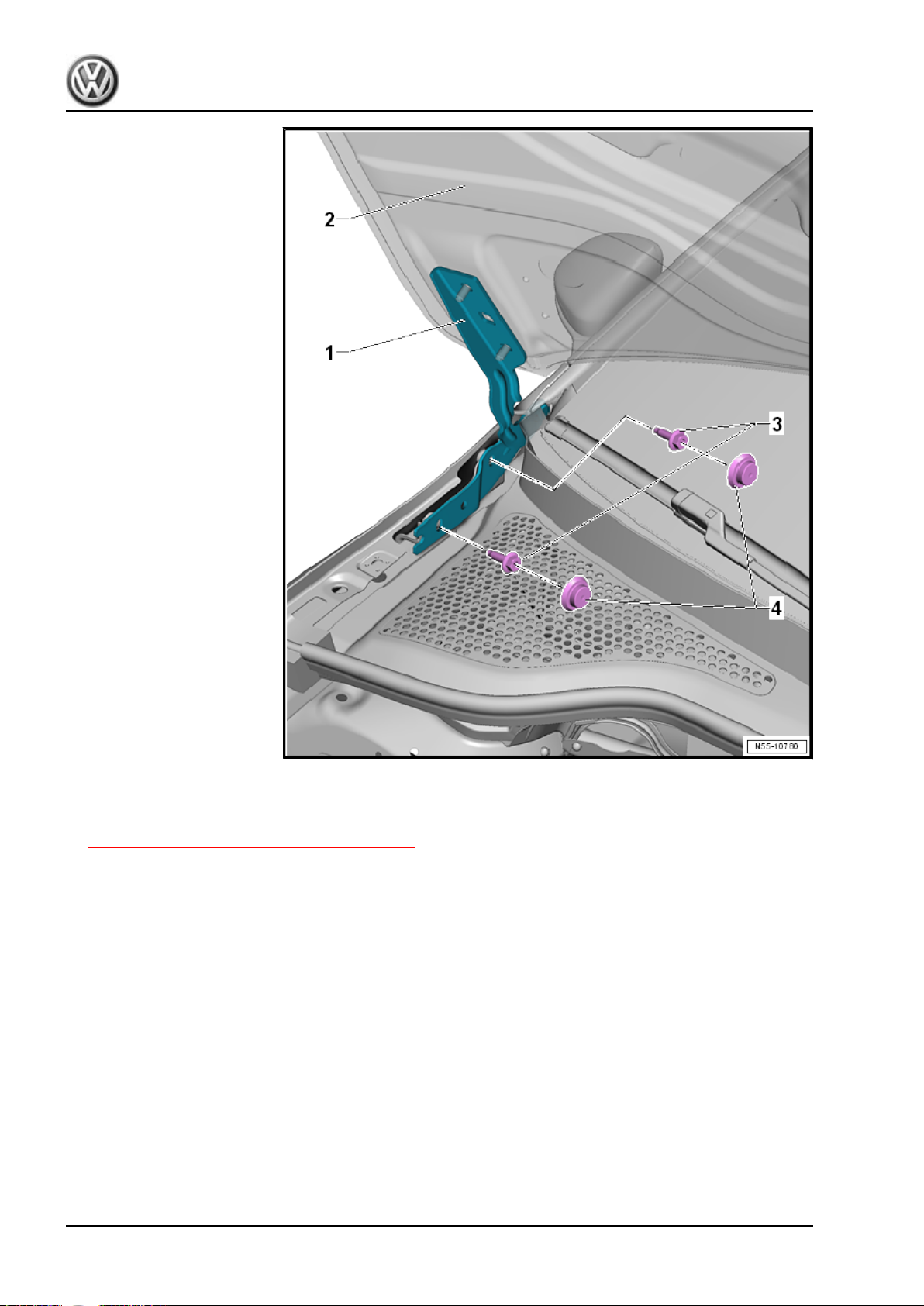
Removing
– Remove the hood -2-. Refer to
⇒ “1.3 Hood, Removing and Installing”, page 26 .
– If equipped, remove the caps -4-.
– Remove the bolts -3-.
– Remove the hinge -1-.
40 Rep. Gr.55 - Hood, Lids
Page 49
Golf 2015 ➤ , Golf Variant 2015 ➤
Body Exterior - Edition 02.2016
Installing
Install the hinge -1- in reverse order of removal.
– Install the hood -2-. Refer to
⇒ “1.3 Hood, Removing and Installing”, page 26 .
Tightening Specifications
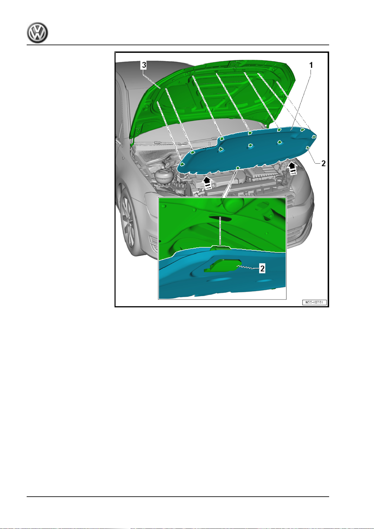
1.11 Insulation, Removing and Installing
Special tools and workshop equipment required
♦ Pry Lever - 80-200-
1. Hood 41
Page 50
Golf 2015 ➤ , Golf Variant 2015 ➤
Body Exterior - Edition 02.2016
Removing
– Pry the clips -2- out of the hood -3- using the Pry Lever -
80-200- .
– Remove the insulation -1- from the oblong holes in direction
of -arrows-.
42 Rep. Gr.55 - Hood, Lids
Page 51
Golf 2015 ➤ , Golf Variant 2015 ➤
Body Exterior - Edition 02.2016
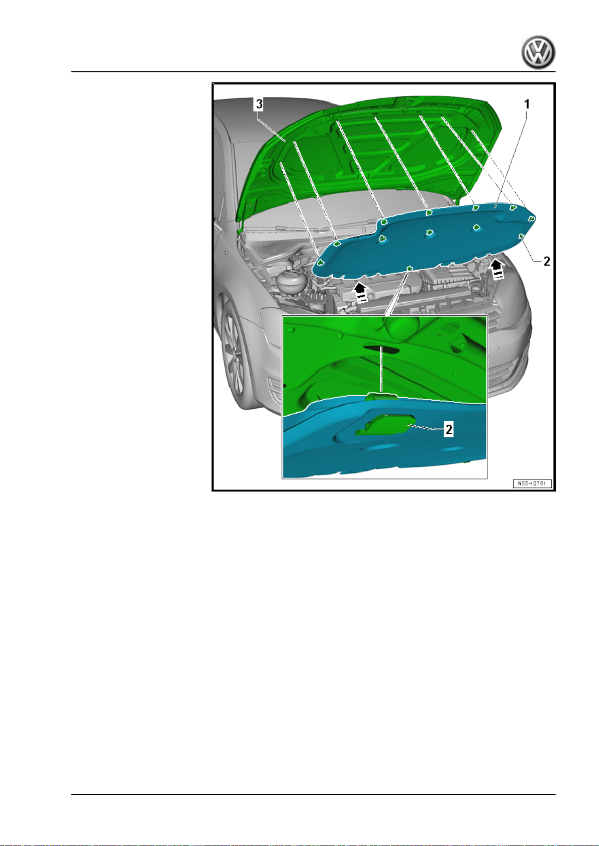
Installing
– Slide the insulation -1- with the mounting tabs -arrows- into the
oblong holes.
– Lock all of the clips -2- into the hood -3-.
1. Hood 43
Page 52
Golf 2015 ➤ , Golf Variant 2015 ➤
Body Exterior - Edition 02.2016
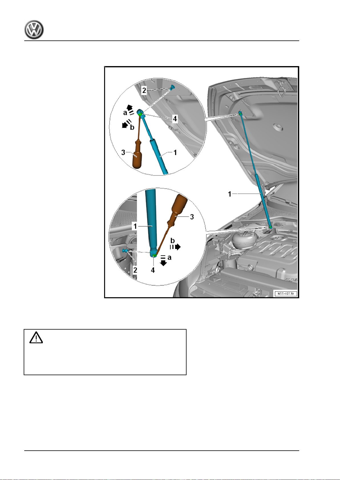
1.12 Gas-Filled Strut, Removing and Installing
Removing
– Open and support the hood.
WARNING
Proceed carefully when reusing a gas-filled strut. Do not pry
the spring clip completely out of the ball socket or the spring
clip will be damaged. The gas-filled strut will spring out of the
mount, resulting in damage or injury to the technician.
– Reach under the spring clip -4- with a small screwdriver -3-.
– Lift the spring clip -4- just far enough so that the spring clip can
be moved over the ball socket in direction of -arrow a-.
– Remove the gas-filled strut -1- from the ball stud -2- in direction
of -arrow b-.
After removing the gas-filled strut -1- immediately slide the spring
clip -4- back again.
44 Rep. Gr.55 - Hood, Lids
Page 53
– The gas-filled strut must be vented when disposing of it. Refer
to ⇒ “1.13 Gas-Filled Strut, Venting”, page 45 .
Installing
– Push the gas-filled strut -1- onto the ball stud -2-.
Tightening Specifications
Component Tightening Specification
Ball stud to the hood or body 20 Nm
1.13 Gas-Filled Strut, Venting
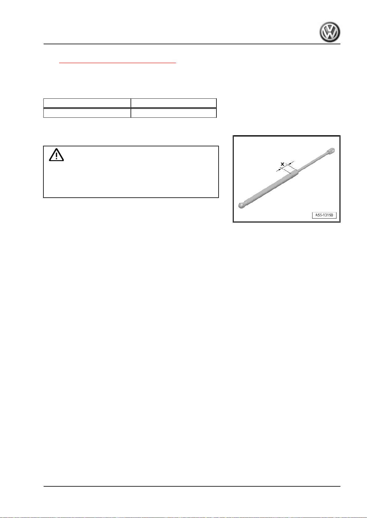
– Clamp the area -x- of the gas strut in the vise, area x = 50 mm.
WARNING
Wear protective eyewear when sawing.
Cover the area of the saw cut with a cleaning cloth.
Dispose of the oil and cleaning cloths properly.
– Cut open the gas-filled strut cylinder within the first third of the
total cylinder length using the piston rod side of the cylinder as
a reference point.
Golf 2015 ➤ , Golf Variant 2015 ➤
Body Exterior - Edition 02.2016
1.14 Release Cable, Removing and Installing
1. Hood 45
Page 54
Golf 2015 ➤ , Golf Variant 2015 ➤
Body Exterior - Edition 02.2016
Removing
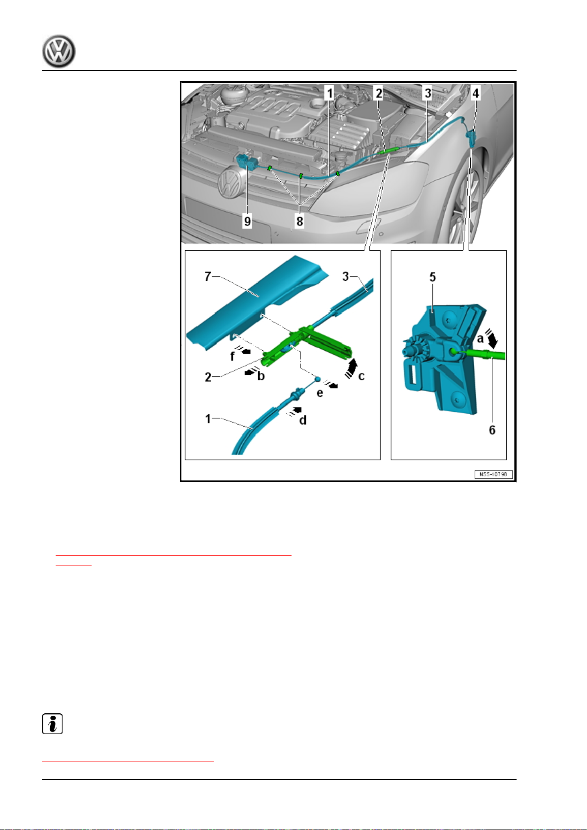
– Open the hood.
– Remove the release lever. Refer to
⇒ “1.7 Hood Release Lever, Removing and Installing”,
page 35 .
– Remove the release cable -6- from the bracket -5- in direction
of -arrow a-.
– Remove the release cable coupling -2- from the support -7- in
direction of -arrow f-.
– Slightly pull out the release cable -1- in direction of -arrow b-.
– Open the cap of the release cable coupling in direction of
-arrow c-.
– Release the release cable -1- in direction of -arrow d- and re‐
move from the release cable coupling -2- in direction of
-arrow e-.
Note
To remove and install the release cable -3-, the support -7- is removed. Refer to
⇒ “1.1 Overview - Lock Carrier”, page 1 .
46 Rep. Gr.55 - Hood, Lids
Page 55
Golf 2015 ➤ , Golf Variant 2015 ➤
Body Exterior - Edition 02.2016
Installing
Note
♦
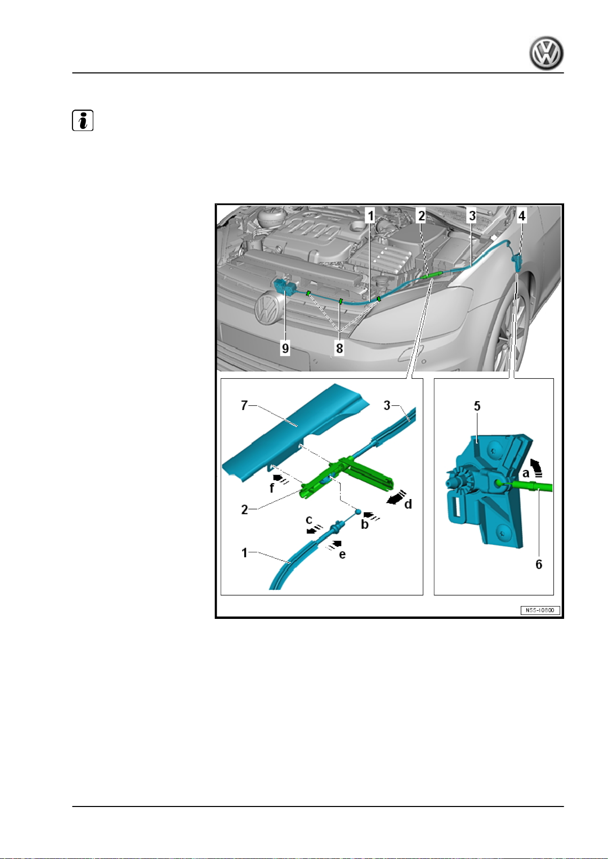
When the release cable -3- is not removed from the bracket, the release cable -1- disengages further when
installing it in the release cable coupling -2-.
♦
The hood then cannot be opened.
– Engage the release cable -1- in the release cable coupling
-2- in direction of -arrow b-.
– Pull the release cable slightly off the release cable coupling in
direction of -arrow c-.
– Close the release cable coupling in direction of -arrow d-.
– Push the release cable -1- in the release cable coupling in
direction of -arrow e-.
– Secure the release cable coupling -2- on the support -7- in
direction of -arrow f-.
– Install the release cable -6- in the bracket -5- in direction of
-arrow a-.
1. Hood 47
Page 56

Golf 2015 ➤ , Golf Variant 2015 ➤
Body Exterior - Edition 02.2016
– Install the release lever. Refer to
⇒ “1.7 Hood Release Lever, Removing and Installing”,
page 35 .
– Before closing the hood, make sure the hood release lever and
the release cable are working correctly.
48 Rep. Gr.55 - Hood, Lids
Page 57
2 Rear Lid
⇒ “2.1 Overview - Rear Lid”, page 49
⇒ “2.2 Rear Lid, Removing and Installing”, page 50
⇒ “2.3 Rear Lid, Adjusting”, page 55
⇒ “2.4 Adjusting Buffer, Removing and Installing”, page 56
⇒ “2.5 Adjusting Buffer, Adjusting”, page 57
⇒ “2.6 Latch, Removing and Installing”, page 58
⇒ “2.7 Actuator, Removing and Installing”, page 60
⇒ “2.8 Hinges, Removing and Installing”, page 64
⇒ “2.9 Catch, Removing and Installing”, page 66
⇒ “2.10 Catch, Adjusting”, page 67
⇒ “2.11 Rear Lid Seal, Removing and Installing”, page 68
⇒ “2.12 Gas-Filled Strut, Removing and Installing”, page 70
⇒ “2.13 Gas-Filled Strut, Venting”, page 72
2.1 Overview - Rear Lid
Golf 2015 ➤ , Golf Variant 2015 ➤
Body Exterior - Edition 02.2016
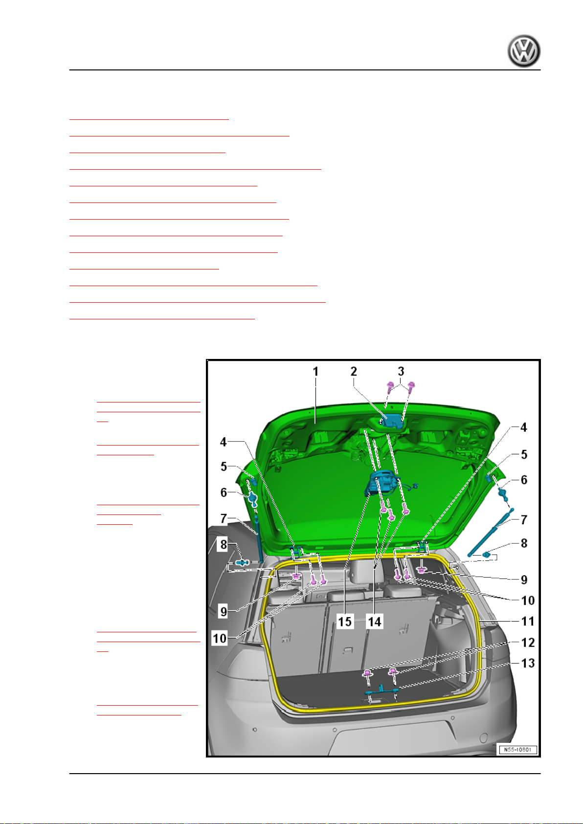
1 - Rear Lid
❑ Removing and instal‐
ling. Refer to
⇒ “2.2 Rear Lid, Remov‐
ing and Installing”, page
50 .
❑ Adjusting. Refer to
⇒ “2.3 Rear Lid, Adjust‐
ing”, page 55 .
2 - Latch
❑ Removing and instal‐
ling. Refer to
⇒ “2.6 Latch, Removing
and Installing”,
page 58 .
3 - Bolts
❑ 20 Nm
❑ Quantity: 2
4 - Hinge
❑ Left and right
❑ Removing and instal‐
ling. Refer to
⇒ “2.8 Hinges, Remov‐
ing and Installing”, page
64 .
5 - Adjusting Buffer
❑ Left and right
❑ Adjusting. Refer to
⇒ “2.5 Adjusting Buffer,
Adjusting”, page 57 .
6 - Ball Stud
❑ 20 Nm + 45°
2. Rear Lid 49
Page 58

Golf 2015 ➤ , Golf Variant 2015 ➤
Body Exterior - Edition 02.2016
7 - Gas-Filled Strut
❑ Removing and installing. Refer to ⇒ “2.12 Gas-Filled Strut, Removing and Installing”, page 70 .
❑ Venting. Refer to ⇒ “2.13 Gas-Filled Strut, Venting”, page 72 .
8 - Ball Stud
❑ 20 Nm + 45°
9 - Hex Nut
❑ 20 Nm + 45°
❑ Quantity: 1 per hinge
10 - Bolts
❑ 10 Nm
❑ Quantity: 2 per hinge
11 - Rear Lid Seal
❑ Removing and installing. Refer to ⇒ “2.11 Rear Lid Seal, Removing and Installing”, page 68 .
12 - Hex Nut
❑ 20 Nm
❑ Quantity: 2
13 - Catch
❑ Removing and installing. Refer to ⇒ “2.9 Catch, Removing and Installing”, page 66 .
❑ Adjusting. Refer to ⇒ “2.10 Catch, Adjusting”, page 67 .
14 - Bolts
❑ 5 Nm
❑ Quantity: 3
15 - Actuator
❑ Removing and installing. Refer to ⇒ “2.7 Actuator, Removing and Installing”, page 60 .
2.2 Rear Lid, Removing and Installing
⇒ “2.2.1 Rear Lid, Removing and Installing, Sedan”, page 50
⇒ “2.2.2 Rear Lid, Removing and Installing, Wagon”, page 53
2.2.1 Rear Lid, Removing and Installing, Se‐
dan
Special tools and workshop equipment required
♦ Torque Wrench 1331 5-50Nm - VAG1331-
50 Rep. Gr.55 - Hood, Lids
Page 59
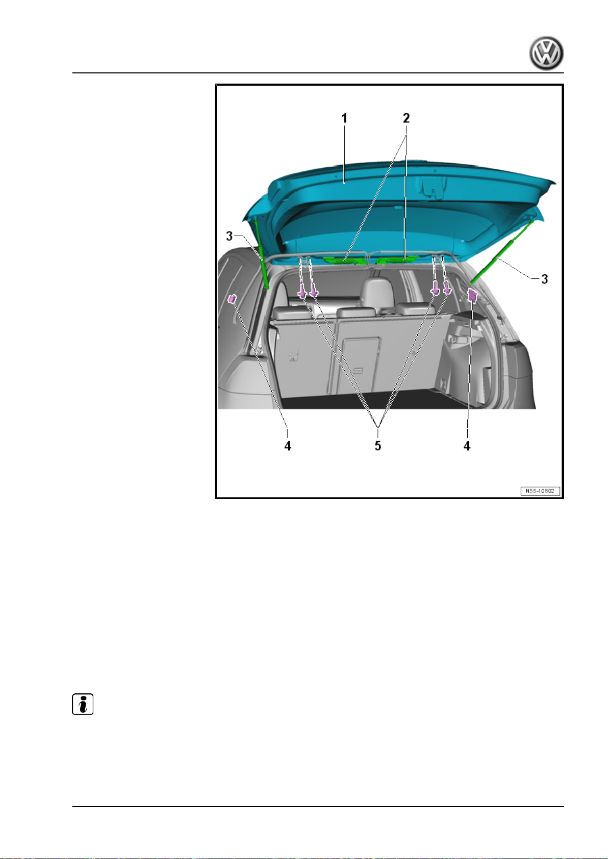
Golf 2015 ➤ , Golf Variant 2015 ➤
Body Exterior - Edition 02.2016
Removing
– Remove the rear lid upper trim panel. Refer to ⇒ Body Interior;
Rep. Gr. 70 ; Luggage Compartment Trim Panels; Rear Lid
Upper Trim Panel, Removing and Installing .
– Remove the rear lid lower trim panel. Refer to ⇒ Body Interior;
Rep. Gr. 70 ; Luggage Compartment Trim Panels; Rear Lid
Lower Trim Panel, Removing and Installing .
– Remove the high-mounted brake lamp. Refer to ⇒ Electrical
Equipment; Rep. Gr. 94 ; High-Mounted Brake Lamp; HighMounted Brake Lamp, Removing and Installing .
– Disconnect the connectors from any electrical components.
– Guide the wires with the rubber grommet -2- out of the rear lid.
Note
The connectors -4- for the wires -2- are located on the C-pillars.
– Loosen, but do not remove, the bolts -5- on the left and right
hinges.
A second technician is required for the rest of the removal pro‐
cedure.
2. Rear Lid 51
Page 60
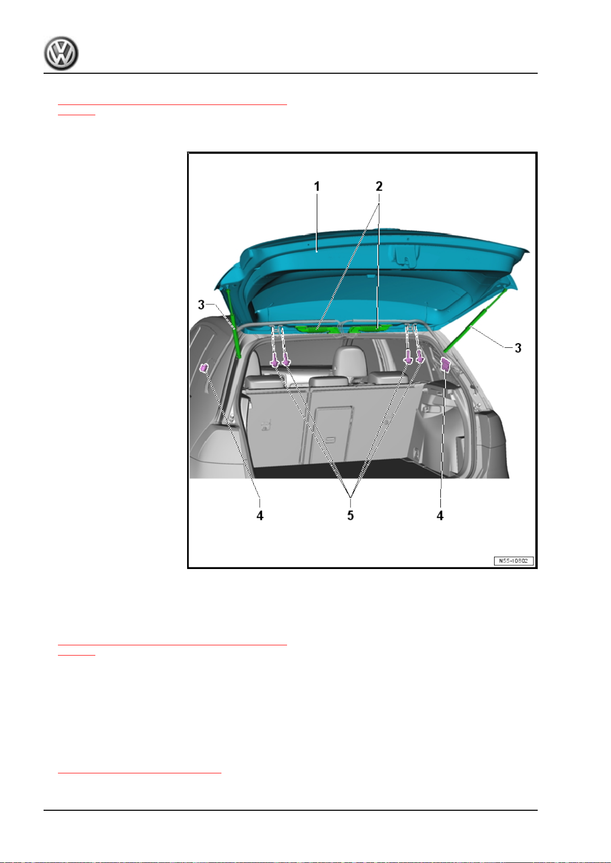
Golf 2015 ➤ , Golf Variant 2015 ➤
Body Exterior - Edition 02.2016
– Remove the gas-filled struts -3-. Refer to
⇒ “2.12 Gas-Filled Strut, Removing and Installing”,
page 70 .
– Now remove the bolts -5- and the rear lid -1-.
Installing
– Install the rear lid -1- with a second technician.
– Install the gas-filled struts -3-. Refer to
⇒ “2.12 Gas-Filled Strut, Removing and Installing”,
page 70 .
– Guide the wires -2- into the rear lid and install the rubber
grommet.
– Connect the connectors of any electrical components.
Installation is performed in reverse order of the removal.
– Perform a function test on the unlocking components before
closing the rear lid.
– Adjust the rear lid. Refer to
⇒ “2.3 Rear Lid, Adjusting”, page 55 .
52 Rep. Gr.55 - Hood, Lids
Page 61
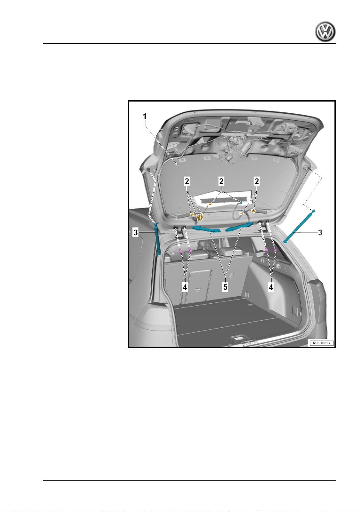
2.2.2 Rear Lid, Removing and Installing, Wagon
Special tools and workshop equipment required
♦ Torque Wrench 1331 5-50Nm - VAG1331-
Golf 2015 ➤ , Golf Variant 2015 ➤
Body Exterior - Edition 02.2016
Removing
– Remove the rear lid upper trim panel. Refer to ⇒ Body Interior;
Rep. Gr. 70 ; Luggage Compartment Trim Panels; Rear Lid
Upper Trim Panel, Removing and Installing .
– Remove the rear lid lower trim panel. Refer to ⇒ Body Interior;
Rep. Gr. 70 ; Luggage Compartment Trim Panels; Rear Lid
Lower Trim Panel, Removing and Installing .
– Remove the high-mounted brake lamp. Refer to ⇒ Electrical
Equipment; Rep. Gr. 94 ; High-Mounted Brake Lamp; HighMounted Brake Lamp, Removing and Installing .
– Disconnect the connectors -2- from the equipped electrical
components.
– Guide the wires with the rubber grommet -5- out of the rear lid.
2. Rear Lid 53
Page 62
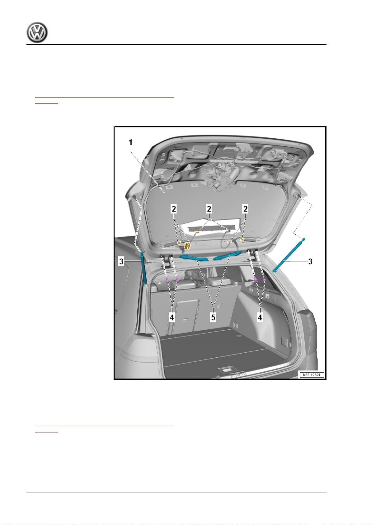
Golf 2015 ➤ , Golf Variant 2015 ➤
Body Exterior - Edition 02.2016
– Loosen the bolts -4- on the left and right hinges, but do not
remove them.
A second technician is required for the rest of the removal pro‐
cedure.
– Remove the gas-filled struts -3-. Refer to
⇒ “2.12 Gas-Filled Strut, Removing and Installing”,
page 70 .
– Now remove the bolts -4- and the rear lid -1-.
Installing
– Install the rear lid -1- with a second technician.
– Install the gas-filled struts -3-. Refer to
⇒ “2.12 Gas-Filled Strut, Removing and Installing”,
page 70 .
– Guide the wires -2- into the rear lid and install the rubber
grommet.
– Connect the connectors of any electrical components.
Installation is performed in reverse order of the removal.
54 Rep. Gr.55 - Hood, Lids
Page 63
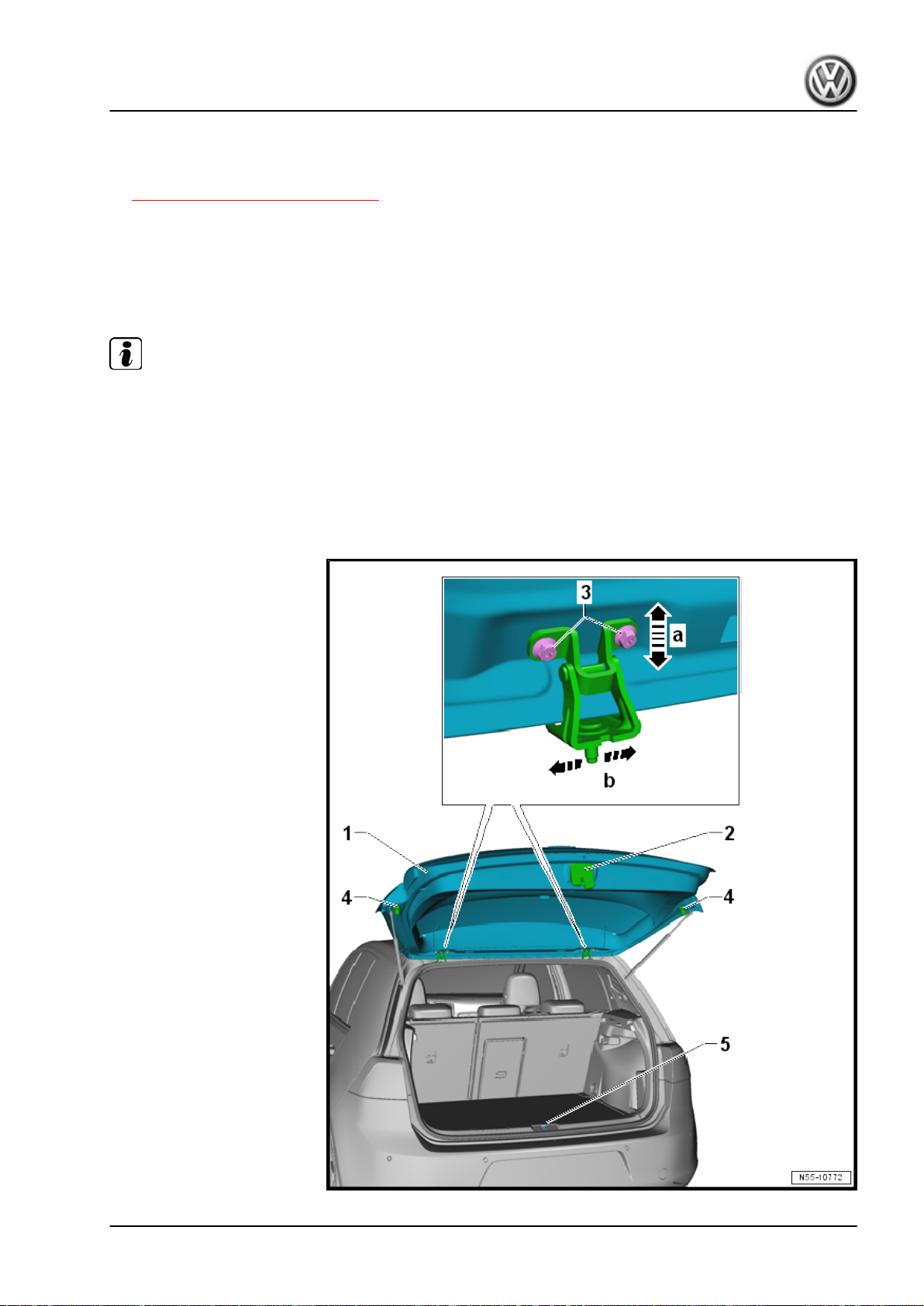
Golf 2015 ➤ , Golf Variant 2015 ➤
Body Exterior - Edition 02.2016
– Perform a function test on the unlocking components before
closing the rear lid.
– Adjust the rear lid. Refer to
⇒ “2.3 Rear Lid, Adjusting”, page 55 .
2.3 Rear Lid, Adjusting
Special tools and workshop equipment required
♦ Torque Wrench 1331 5-50Nm - VAG1331-
♦ Gauge - Gap Adjustment - 3371-
Note
♦
The vehicle must be on all four wheels when adjusting the rear lid.
♦
The latch -2- is bolted directly to the rear lid -1-. The latch cannot be adjusted.
♦
The left and right adjusting buffers -4- are not meant for adjusting. They stabilize and cushion the rear lid.
♦
The rear lid is properly adjusted when there is an overall even gap dimension when closed. It is not too far
inward or outward. And the contours align.
♦
The rear lid must engage in the striker without great force.
2. Rear Lid 55
Page 64
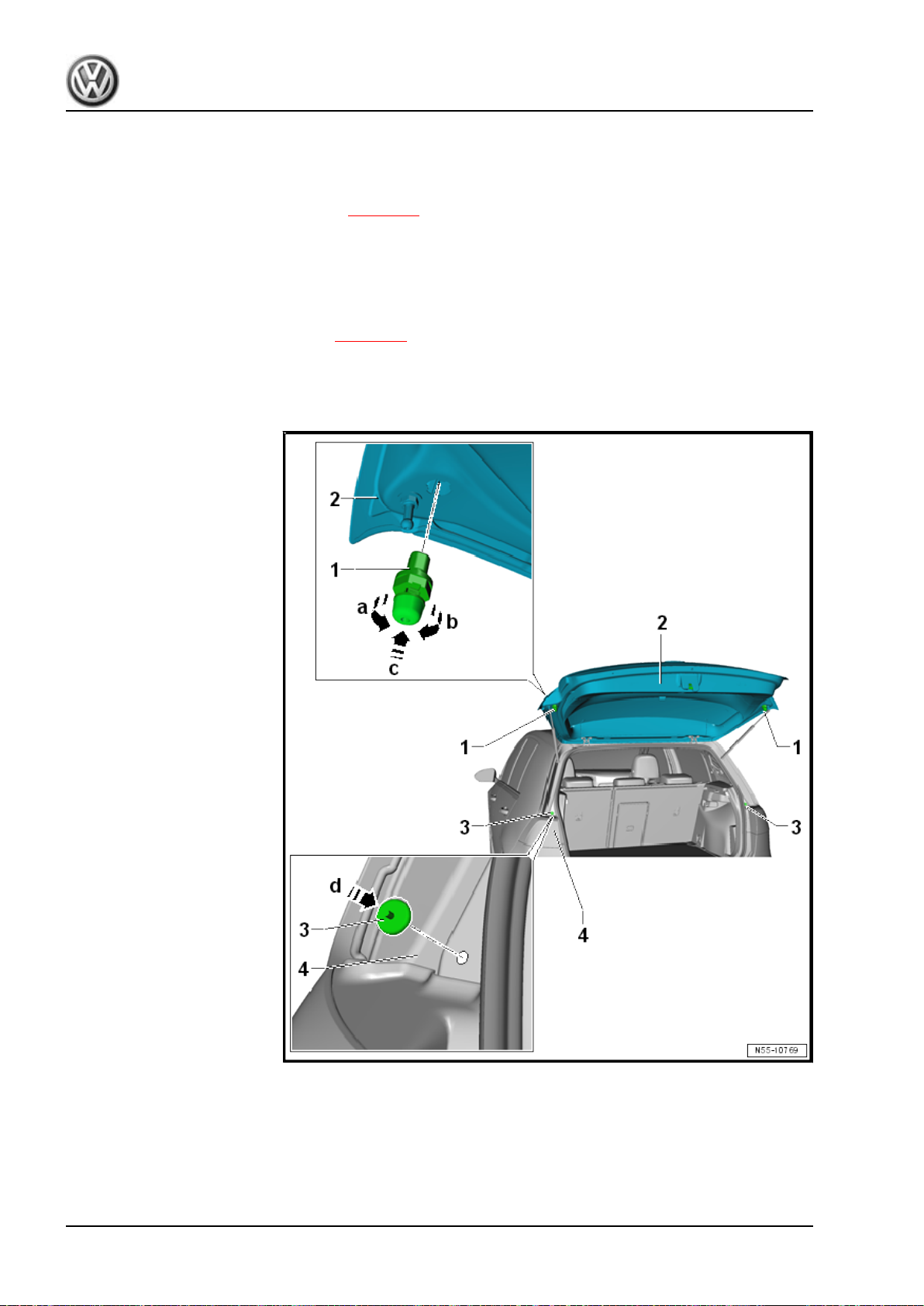
Golf 2015 ➤ , Golf Variant 2015 ➤
Body Exterior - Edition 02.2016
To adjust or check the gap dimensions, use the Gauge - Gap
Adjustment - 3371- . Refer to ⇒ Body Repair; Rep. Gr. 00 ; Body
Gap Dimensions; Rear Body .
– Loosen the catch -5- and adjust at the hinge and the adjusting
buffer after adjustment work. Refer to ⇒ page 67 .
– By loosening the left and right bolts -3-, the rear lid -1- can be
adjusted in the oversized holes on the hinge -a arrows- and
-b arrows-.
– After adjusting, perform corrosion protection measures on the
hinge and bolts -3-.
– Adjust the adjusting buffer. Refer to ⇒ page 57 .
Tightening Specifications
2.4 Adjusting Buffer, Removing and Installing
Removing
– Turn the entire buffer -1- 90° in direction of -arrow a- to remove
the adjusting buffer.
– Remove the buffer from the rear lid -2-.
56 Rep. Gr.55 - Hood, Lids
Page 65
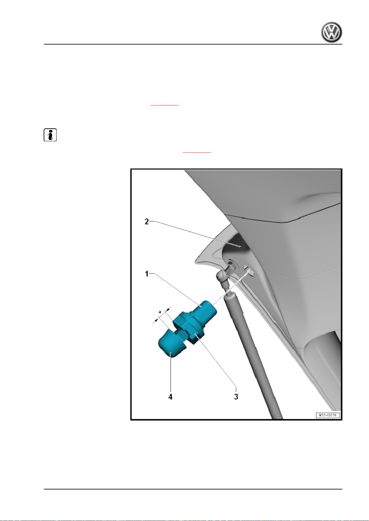
Installing
– Check the stop -3- for proper seating in the side panel -4-.
– To install, insert the entire buffer -1- at a right angle into the
rear lid -2- in direction of -arrow c-.
– Turn the buffer -1- 90° in direction of -arrow b-.
– Adjust adjusting buffer -1-. Refer to ⇒ page 57 .
2.5 Adjusting Buffer, Adjusting
Note
If necessary, replace the adjusting buffer. Refer to ⇒ page 56 .
Golf 2015 ➤ , Golf Variant 2015 ➤
Body Exterior - Edition 02.2016
– Loosen the clamping screw -4- until it is visible in the rubber
buffer.
– Pull the locking retainer -3- out of the adjusting buffer -1-.
– Set the locking retainer to dimension -a- = 12.5 mm.
– Close the rear lid in the initial locking position using light pres‐
sure over the center.
2. Rear Lid 57
Page 66
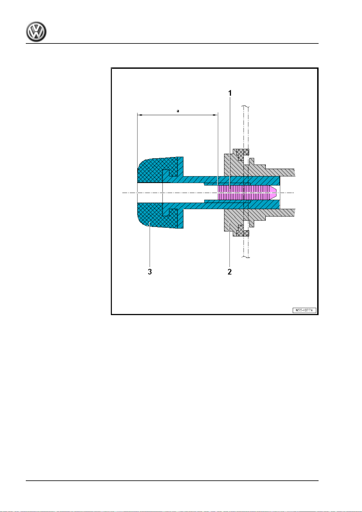
Golf 2015 ➤ , Golf Variant 2015 ➤
Body Exterior - Edition 02.2016
– Open the rear lid again.
– Screw in the clamping screw -1- of the adjusting buffer -2- to
a depth of dimension -a- = 20 mm.
– Check the adjustment.
2.6 Latch, Removing and Installing
Special tools and workshop equipment required
♦ Torque Wrench 1331 5-50Nm - VAG1331-
58 Rep. Gr.55 - Hood, Lids
Page 67
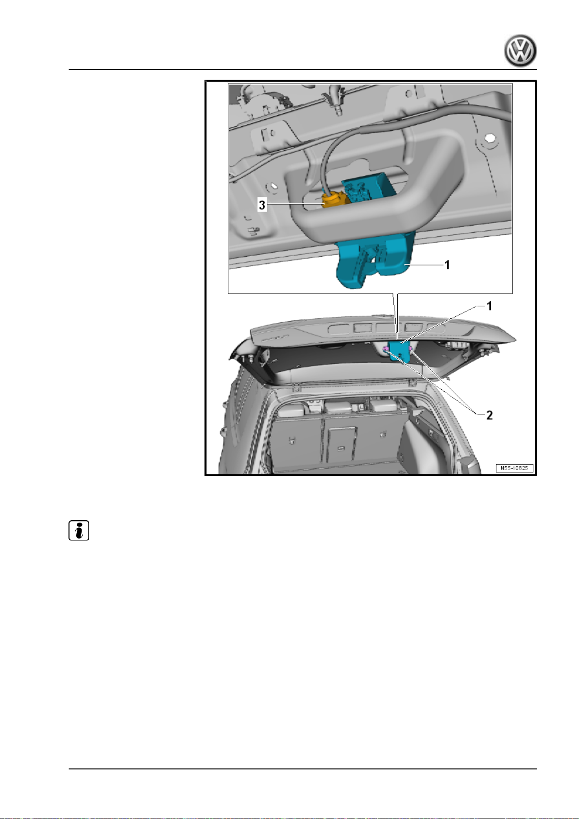
Golf 2015 ➤ , Golf Variant 2015 ➤
Body Exterior - Edition 02.2016
Removing
Note
If the rear lid does not open, use the emergency release inside the rear lid trim panel to open it manually. Refer
to the Owner's Manual.
– Remove the rear lid lower trim panel. Refer to ⇒ Body Interior;
Rep. Gr. 70 ; Luggage Compartment Trim Panels; Rear Lid
Lower Trim Panel, Removing and Installing .
– Disconnect the connector -3- from the latch -1-.
– Remove the bolts -2- and remove the latch -1- from the rear
lid.
2. Rear Lid 59
Page 68
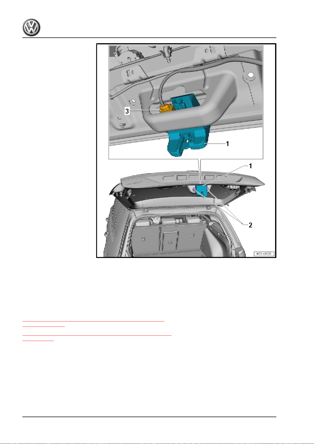
Golf 2015 ➤ , Golf Variant 2015 ➤
Body Exterior - Edition 02.2016
Installing
– Insert the latch -1- into the rear lid and tighten the bolts -2-.
– Connect the connector -3- to the latch -1-.
Tightening Specifications
2.7 Actuator, Removing and Installing
⇒ “2.7.1 Actuator, Removing and Installing, without Rearview
Camera”, page 60
⇒ “2.7.2 Actuator, Removing and Installing, with Rearview Cam‐
era”, page 62
2.7.1 Actuator, Removing and Installing, with‐
out Rearview Camera
Special tools and workshop equipment required
♦ Torque Wrench 1331 5-50Nm - VAG1331-
60 Rep. Gr.55 - Hood, Lids
Page 69
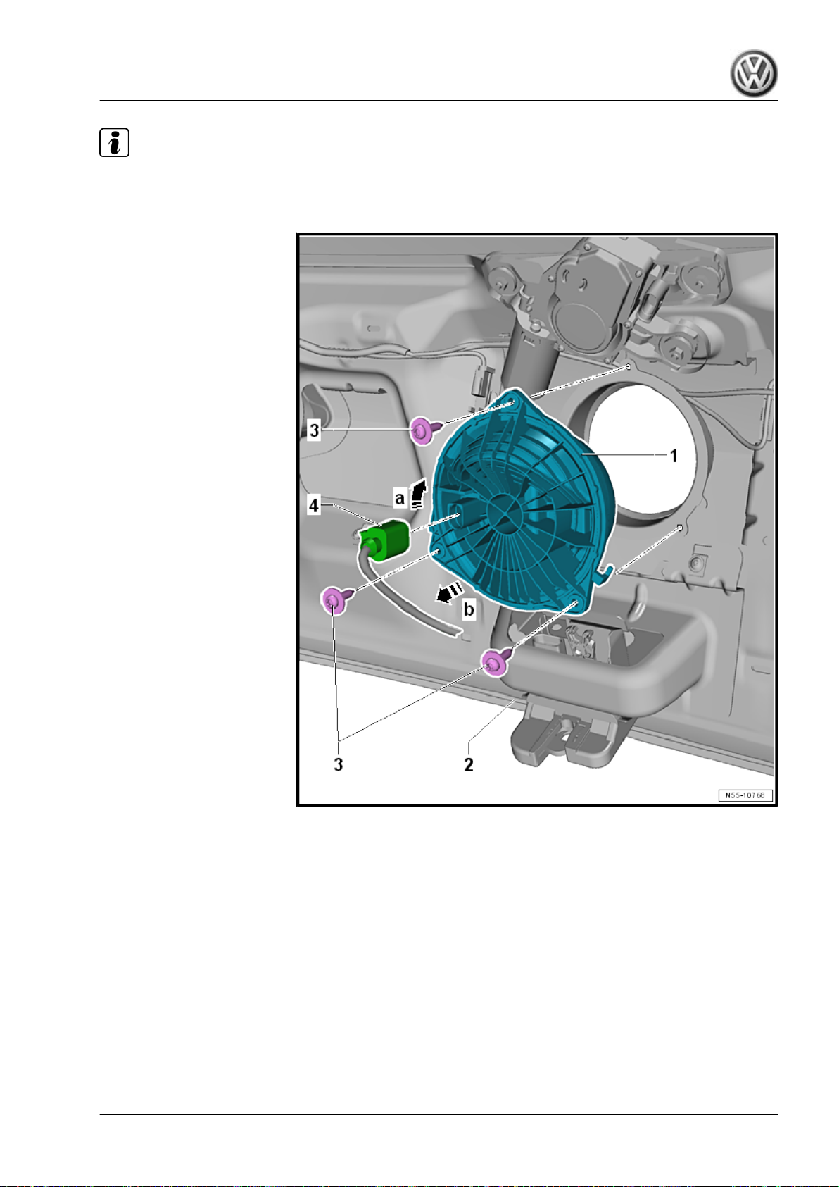
Note
The brand emblem can be replaced separately. Refer to
⇒ “9.4 Rear Emblem, Removing and Installing”, page 456 .
Golf 2015 ➤ , Golf Variant 2015 ➤
Body Exterior - Edition 02.2016
Removing
– Remove the rear lid lower trim panel. Refer to ⇒ Body Interior;
Rep. Gr. 70 ; Luggage Compartment Trim Panels; Rear Lid
Lower Trim Panel, Removing and Installing .
– Disconnect the connector -4- from the actuator connection
-1-.
– Remove the bolts -3-.
– Turn the actuator -1- slightly in direction of -arrow a- and re‐
move it from the rear lid -2- in direction of -arrow b-.
In case of an electrical malfunction, the rear lid can be opened
using the latch emergency release. There is an opening in the
rear lid trim panel to reach the emergency release.
2. Rear Lid 61
Page 70
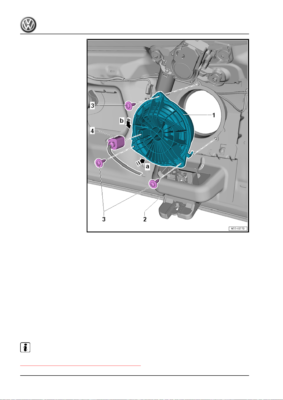
Golf 2015 ➤ , Golf Variant 2015 ➤
Body Exterior - Edition 02.2016
Installing
– Insert the actuator -1- into the rear lid -2- in direction of
-arrow a- and turn it slightly in direction of -arrow b-.
– Install and tighten the bolts -3-.
– Secure the connector -4- on the actuator.
– Install the rear lid lower trim panel. Refer to ⇒ Body Interior;
Rep. Gr. 70 ; Luggage Compartment Trim Panels; Rear Lid
Lower Trim Panel, Removing and Installing .
Tightening Specifications
2.7.2 Actuator, Removing and Installing, with Rearview Camera
Special tools and workshop equipment required
♦ Torque Wrench 1331 5-50Nm - VAG1331-
Note
The brand emblem can be replaced separately. Refer to
⇒ “9.4 Rear Emblem, Removing and Installing”, page 456 .
62 Rep. Gr.55 - Hood, Lids
Page 71
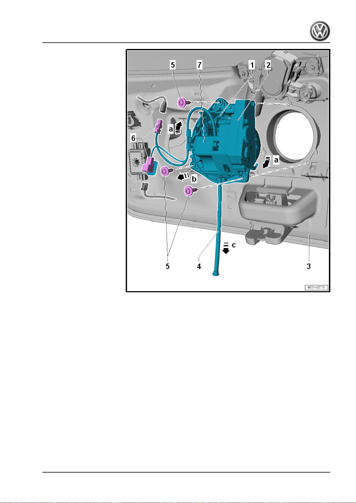
Golf 2015 ➤ , Golf Variant 2015 ➤
Body Exterior - Edition 02.2016
Removing
– Remove the rear lid lower trim panel. Refer to ⇒ Body Interior;
Rep. Gr. 70 ; Luggage Compartment Trim Panels; Rear Lid
Lower Trim Panel, Removing and Installing .
– Disconnect the connectors -6-.
– Remove the screws -5-.
– Turn the actuator -1- slightly in direction of -a arrows- and re‐
move it from the rear lid -3- in direction of -b arrow-.
– Remove the water drain hose -4- from the actuator in direction
of -arrow c-.
In case of an electrical malfunction, the rear lid can be opened
using the latch emergency release. There is an opening in the
rear lid trim panel to reach the emergency release.
Notes and procedures for the rearview camera -7- and the ac‐
tuator -2-. Refer to ⇒ Communication; Rep. Gr. 91 ; Rearview
Camera System .
2. Rear Lid 63
Page 72
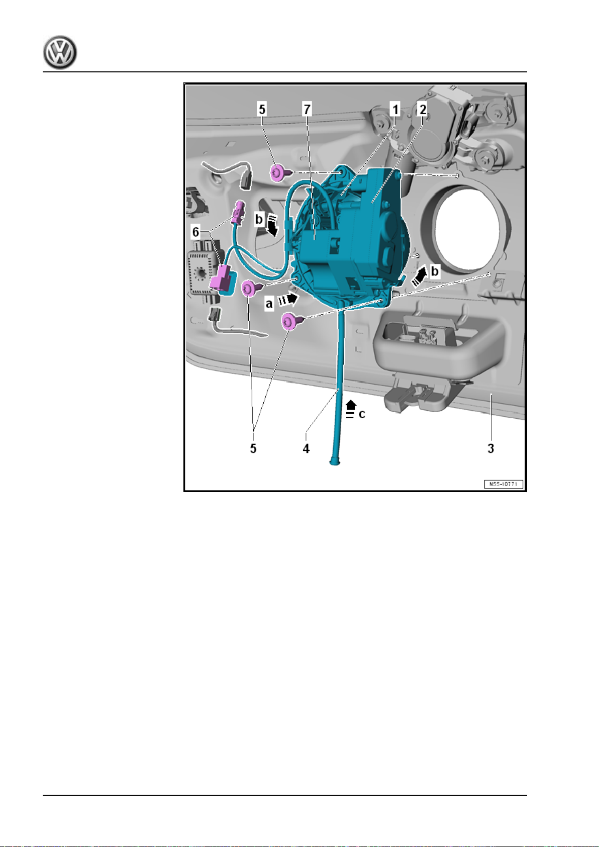
Golf 2015 ➤ , Golf Variant 2015 ➤
Body Exterior - Edition 02.2016
Installing
– Insert the actuator -1- into the rear lid -3- in direction of
-arrow a- and turn it slightly in direction of -b arrows-.
– Secure the water drain hose -4- on the actuator in direction of
-arrow c-.
– Tighten the bolts -5-.
– Secure the connectors -6-.
– Install the rear lid lower trim panel. Refer to ⇒ Body Interior;
Rep. Gr. 70 ; Luggage Compartment Trim Panels; Rear Lid
Lower Trim Panel, Removing and Installing .
Tightening Specifications
2.8 Hinges, Removing and Installing
Special tools and workshop equipment required
♦ Torque Wrench 1331 5-50Nm - VAG1331-
64 Rep. Gr.55 - Hood, Lids
Page 73
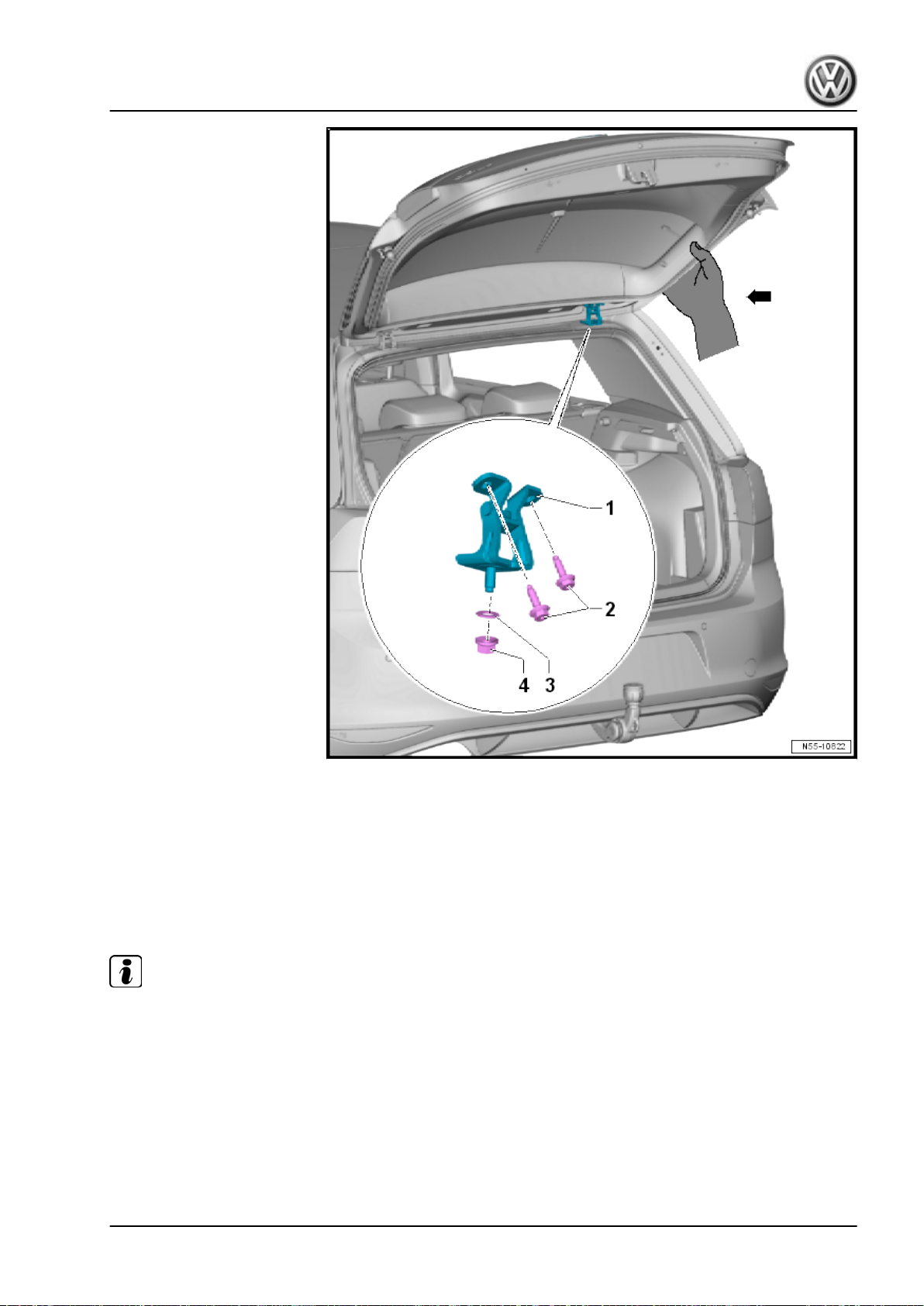
Golf 2015 ➤ , Golf Variant 2015 ➤
Body Exterior - Edition 02.2016
Removing
– Lower the headliner near the hinge mount. Refer to ⇒ Body
Interior; Rep. Gr. 70 ; Roof Trim Panels; Headliner, Removing
and Installing .
– The headliner can now be lowered far enough so that the hex
nut -4- can be removed without damaging the headliner.
– Loosen the hex nuts -4- and bolts -2-, but do not remove them.
Note
♦
Tape off the roof edge and the upper edge of the rear lid, to prevent paint damage.
♦
For the following work procedures, a second technician must hold the rear lid in at the bottom -arrow-.
♦
The gas-filled struts remain installed.
– Remove the hex nut -4- and bolts -2-.
– Remove the hinge -1-.
2. Rear Lid 65
Page 74
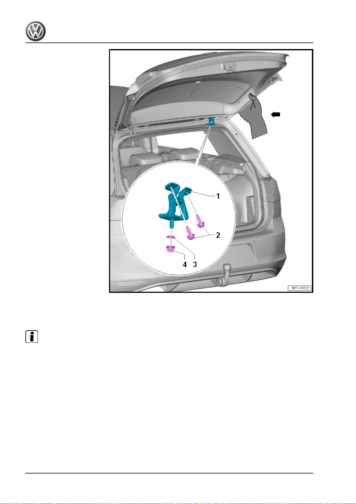
Golf 2015 ➤ , Golf Variant 2015 ➤
Body Exterior - Edition 02.2016
Installing
Install the hinge -1- in reverse order of removal.
Note
♦
Make sure that the washer -3- is seated correctly.
♦
Recreate the observed sealing procedures.
Tightening Specifications
2.9 Catch, Removing and Installing
Special tools and workshop equipment required
♦ Torque Wrench 1331 5-50Nm - VAG1331-
66 Rep. Gr.55 - Hood, Lids
Page 75
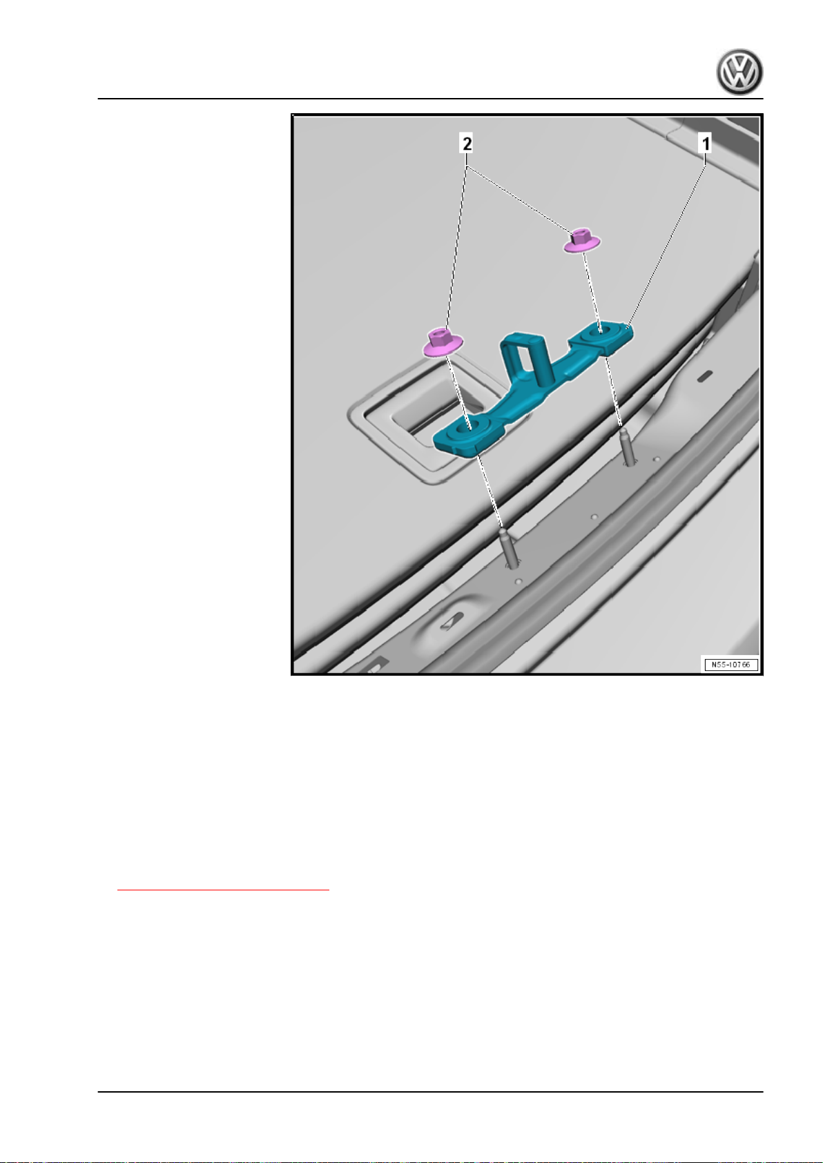
Golf 2015 ➤ , Golf Variant 2015 ➤
Body Exterior - Edition 02.2016
Removing
– Remove the lock carrier trim panel. Refer to ⇒ Body Interior;
Rep. Gr. 70 ; Luggage Compartment Trim Panels; Lock Car‐
rier Trim Panel, Removing and Installing .
– Remove the hex nuts -2- and remove the catch -1- from the
lock carrier.
Installing
– Install the catch -1- with the hex nuts -2- on the lock carrier.
– Adjust the catch. Refer to
⇒ “2.10 Catch, Adjusting”, page 67 .
– Install the lock carrier trim panel. Refer to ⇒ Body Interior; Rep.
Gr. 70 ; Luggage Compartment Trim Panels; Lock Carrier
Trim Panel, Removing and Installing .
Tightening Specifications
2.10 Catch, Adjusting
Special tools and workshop equipment required
♦ Torque Wrench 1331 5-50Nm - VAG1331-
2. Rear Lid 67
Page 76
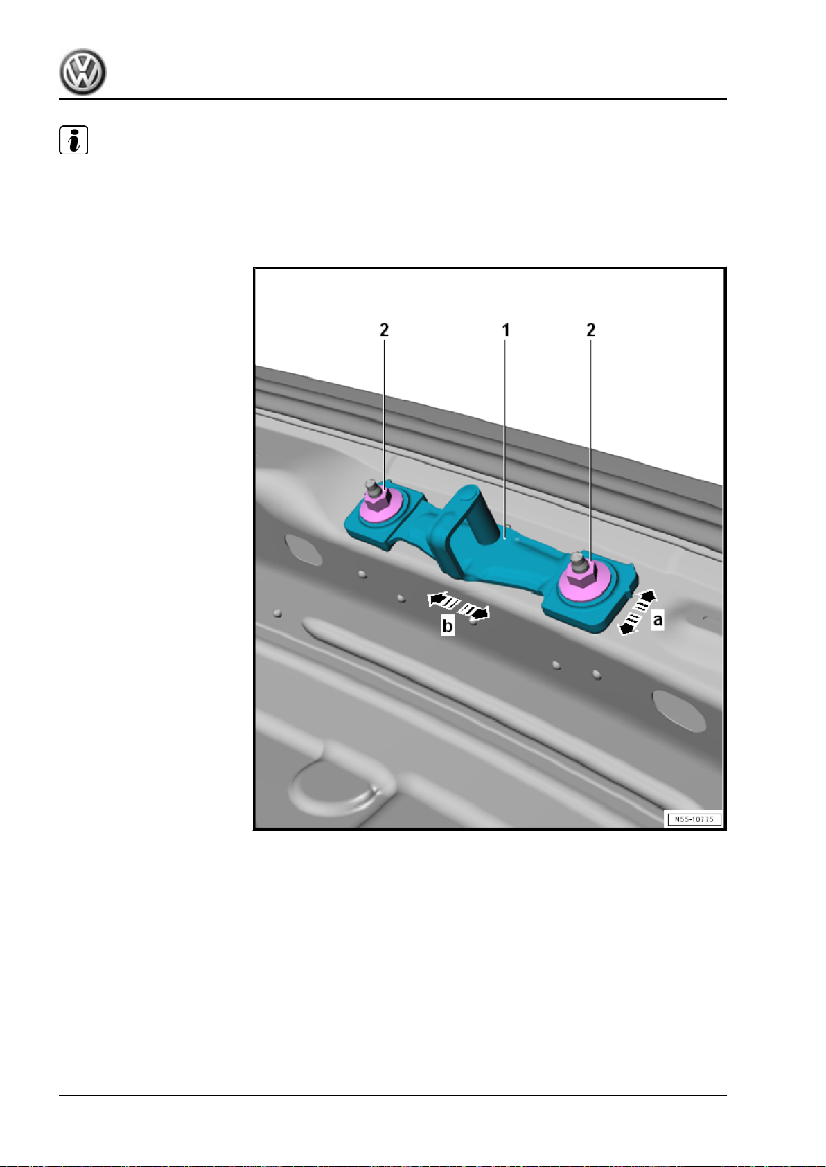
Golf 2015 ➤ , Golf Variant 2015 ➤
Body Exterior - Edition 02.2016
Note
♦
By loosening the hex nuts -2-, the catch -1- can be moved inside the oversized holes in direction of
-arrows a and b-.
♦
Adjust the catch -1- so that the rear lid latch opening with the rotary latch engages with the center of the
catch -1-.
– Remove the lock carrier trim panel. Refer to ⇒ Body Interior;
Rep. Gr. 70 ; Luggage Compartment Trim Panels; Lock Car‐
rier Trim Panel, Removing and Installing .
– Loosen the hex nuts -2-.
– Move the catch -1- into the upper position and tighten the hex
nuts -2-.
– Close the rear lid and check the adjustment.
Tightening Specifications
2.11 Rear Lid Seal, Removing and Installing
The seal on the rear lid is equipped at the factory with a sealant,
applied to body flange and then rolled on.
68 Rep. Gr.55 - Hood, Lids
Page 77
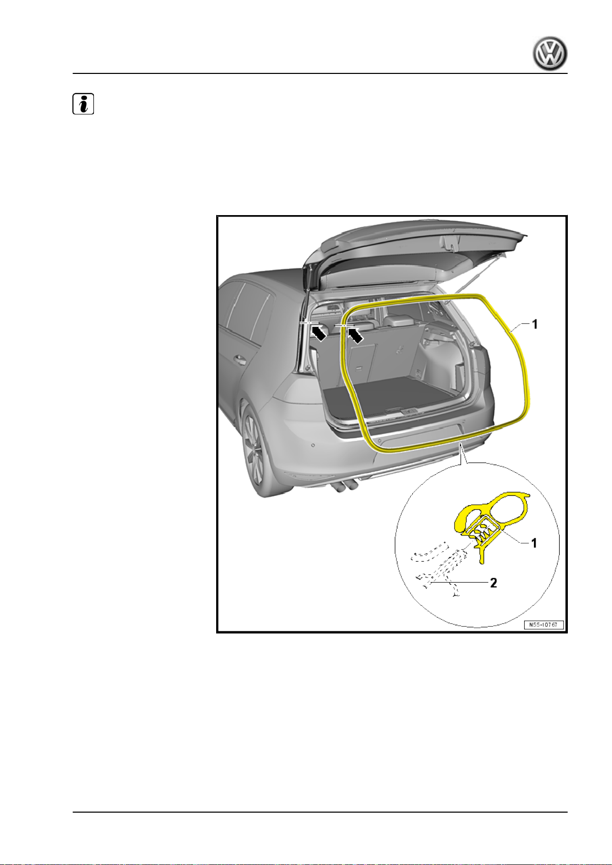
Golf 2015 ➤ , Golf Variant 2015 ➤
Body Exterior - Edition 02.2016
Note
♦
When the seal is removed, the sealant spreads on the inner side of the seal and the sides bend up slightly.
If the seal is being reinstalled, the sealing strength and a secure fit are no longer guaranteed.
♦
For this reason, every seal that has been removed completely must be replaced with a so-called “hammerstroke seal”.
♦
For partially removed seals, press the seal flanks together before installing.
Removing
– Remove the seal -1- from the body flange -2-.
Installing
– Align the seal -1- with the vulcanized point to the gas-filled strut
assembly -arrows-.
– Press in the seal -1- by hand evenly onto the body flange.
2. Rear Lid 69
Page 78
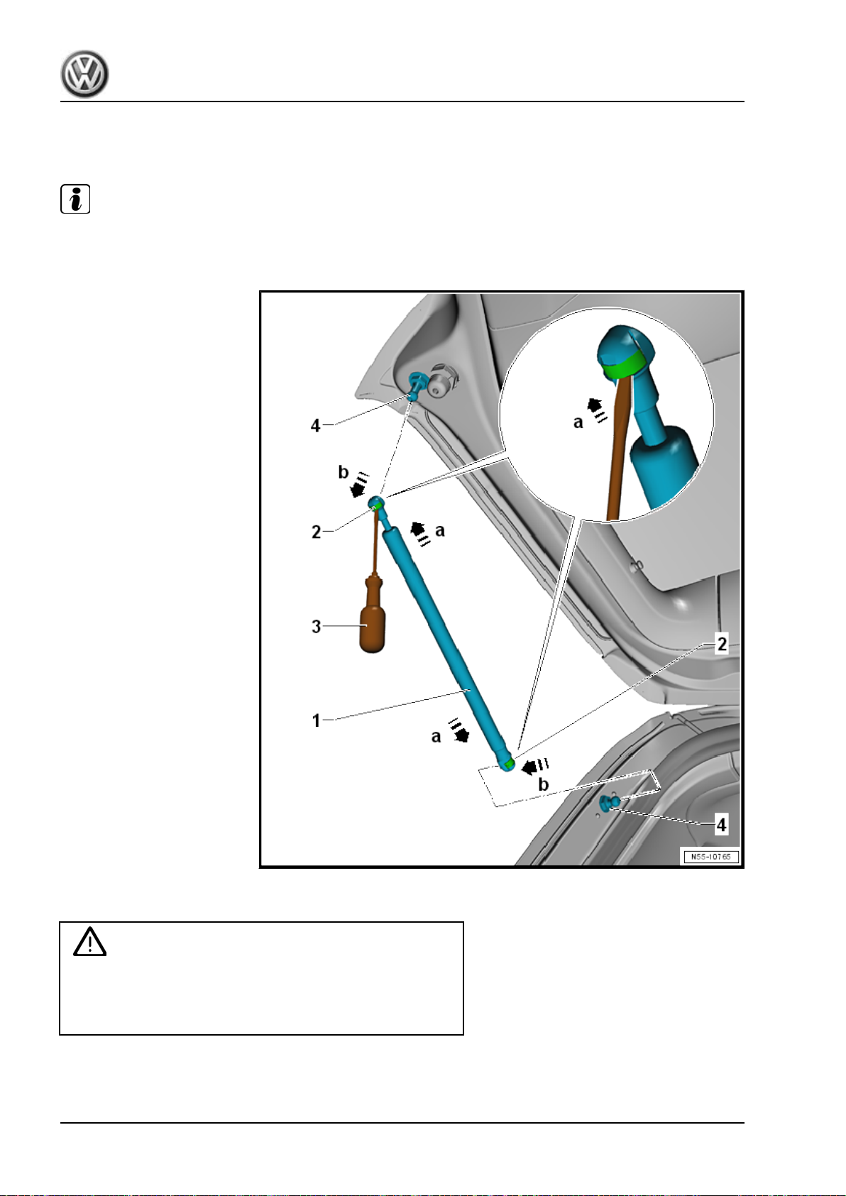
Golf 2015 ➤ , Golf Variant 2015 ➤
Body Exterior - Edition 02.2016
2.12 Gas-Filled Strut, Removing and Installing
Removing
Note
The rear lid must be supported when removing a gas-filled strut. One gas-filled strut alone cannot hold the rear
lid open.
– Open the rear lid and support it.
WARNING
Proceed carefully when reusing a gas-filled strut. The spring
clip must not be pried completely out of the ball socket, other‐
wise it will be damaged. The gas-filled strut will spring out of
the mount, resulting in damage and/or injury to the technician.
– Insert a small screwdriver -3- under the spring clips -2-.
– Lift the spring clips -2- just far enough in direction of
-a arrows- so that they can be moved over the ball sockets.
70 Rep. Gr.55 - Hood, Lids
Page 79
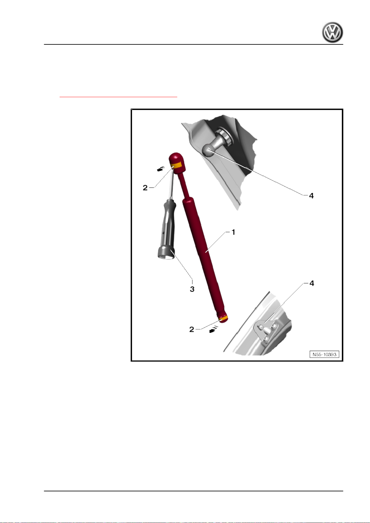
– Remove the gas-filled strut -1- from the ball stud -4- in direction
of -b arrows-.
Slide the spring clips -2- back on immediately after removing the
gas-filled strut.
– The gas-filled strut must be vented when disposing of it. Refer
to ⇒ “2.13 Gas-Filled Strut, Venting”, page 72 .
Golf 2015 ➤ , Golf Variant 2015 ➤
Body Exterior - Edition 02.2016
Installing
– Push the gas-filled strut ball sockets -1- onto the ball stud -4-
until the ball sockets engage audibly on the ball stud.
2. Rear Lid 71
Page 80
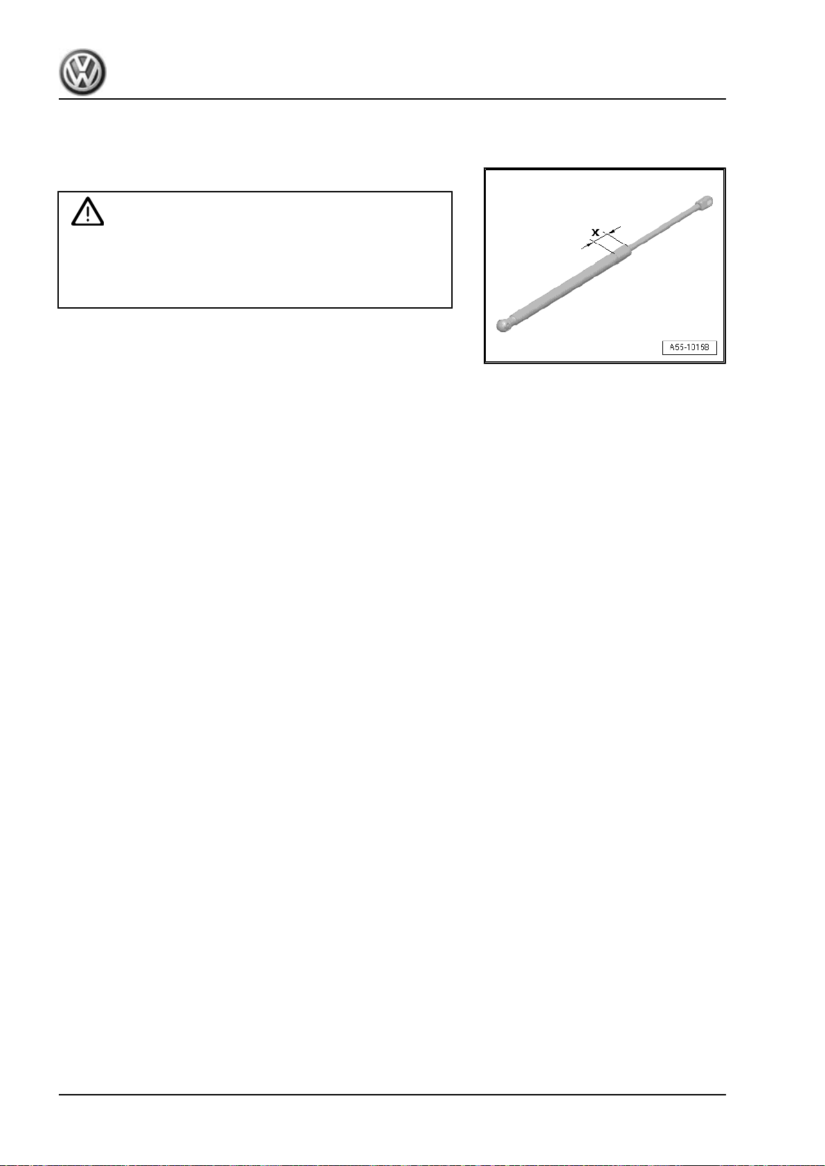
Golf 2015 ➤ , Golf Variant 2015 ➤
Body Exterior - Edition 02.2016
Tightening Specifications
2.13 Gas-Filled Strut, Venting
– Clamp the area -x- of the gas strut in the vise, area x = 50 mm.
WARNING
Wear protective eyewear when sawing.
Cover the area of the saw cut with a cleaning cloth.
Dispose of the oil and cleaning cloths properly.
– Cut open the cylinder of the gas-filled strut within the first third
of the total cylinder length, using the piston rod side of the
cylinder as a reference point.
72 Rep. Gr.55 - Hood, Lids
Page 81
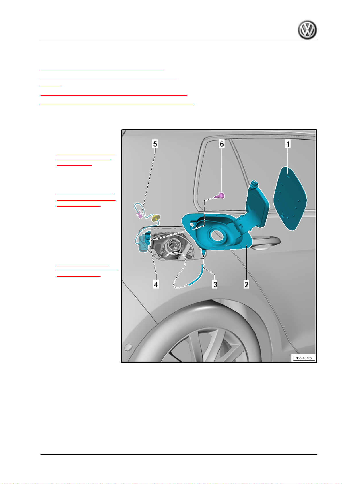
3 Fuel Filler Door Unit
⇒ “3.1 Overview - Fuel Filler Door Unit”, page 73
⇒ “3.2 Fuel Filler Door Unit, Removing and Installing”,
page 74
⇒ “3.3 Fuel Filler Door, Removing and Installing”, page 76
⇒ “3.4 Adjusting Element, Removing and Installing”, page 77
3.1 Overview - Fuel Filler Door Unit
1 - Fuel Filler Door
❑ Removing and instal‐
ling. Refer to
⇒ “3.3 Fuel Filler Door,
Removing and Instal‐
ling”, page 76 .
2 - Fuel Filler Door Unit
❑ Removing and instal‐
ling. Refer to
⇒ “3.2 Fuel Filler Door
Unit, Removing and In‐
stalling”, page 74 .
3 - Water Drain Hose
❑ Routed between the
wheel housing and the
wheel housing liner
4 - Adjusting Element
❑ Removing and instal‐
ling. Refer to
⇒ “3.4 Adjusting Ele‐
ment, Removing and In‐
stalling”, page 77 .
5 - Connector
6 - Screw
❑ 1.5 Nm
Golf 2015 ➤ , Golf Variant 2015 ➤
Body Exterior - Edition 02.2016
3. Fuel Filler Door Unit 73
Page 82
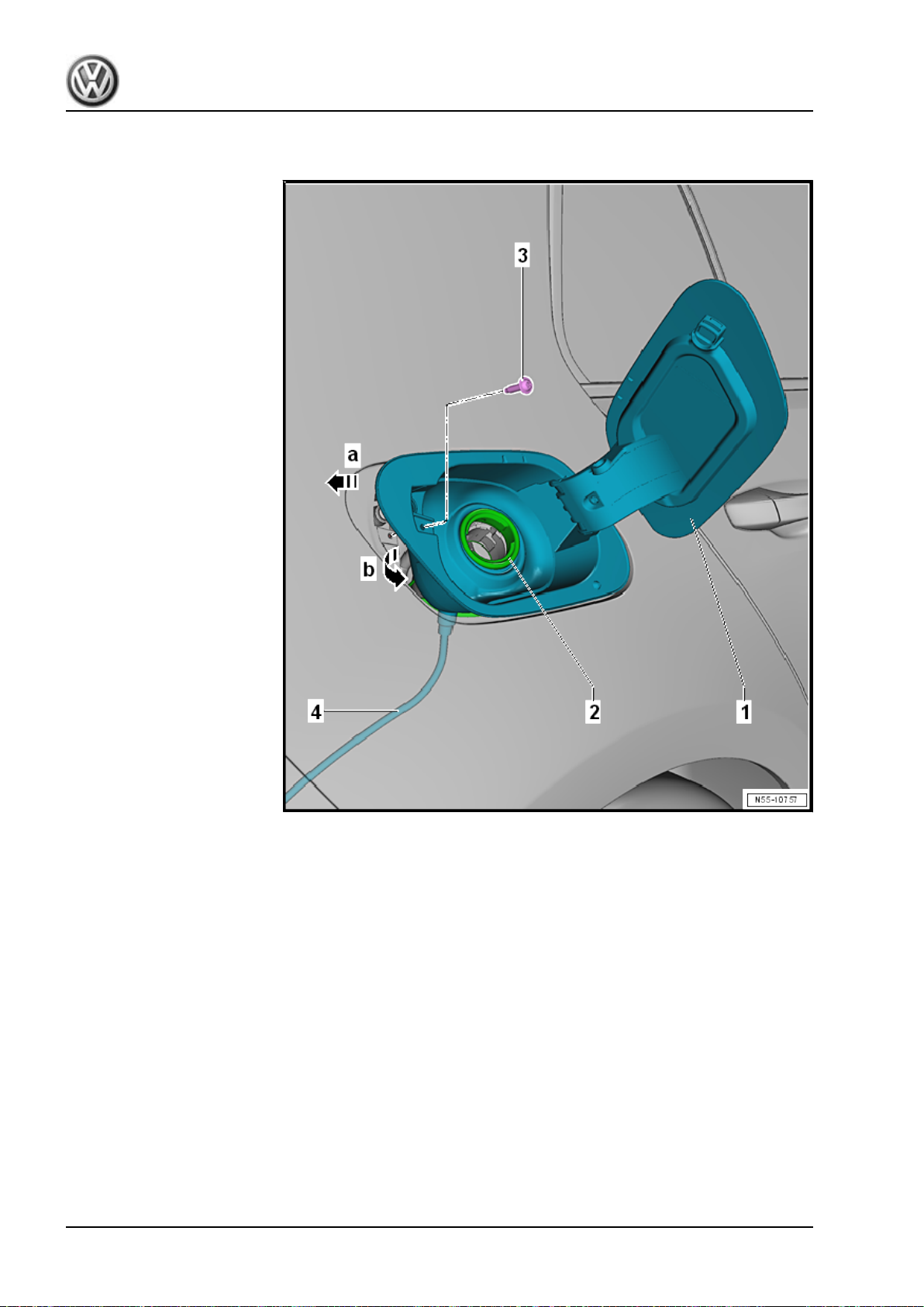
Golf 2015 ➤ , Golf Variant 2015 ➤
Body Exterior - Edition 02.2016
3.2 Fuel Filler Door Unit, Removing and Installing
Removing
– Remove the fuel filler cap.
– Remove the bolt -3-.
– Remove the fuel filler door unit boot from the filler neck -2-.
– If equipped, remove the fuel filler door unit boot from the re‐
ducing agent filler neck.
– Remove the fuel filler door unit slightly toward the rear in di‐
rection of -arrow a- out of the retainers.
– Tilt the fuel filler door unit -1- out of the side panel in direction
of -arrow b-.
– Guide the water drain hose -4- out of the side panel.
74 Rep. Gr.55 - Hood, Lids
Page 83
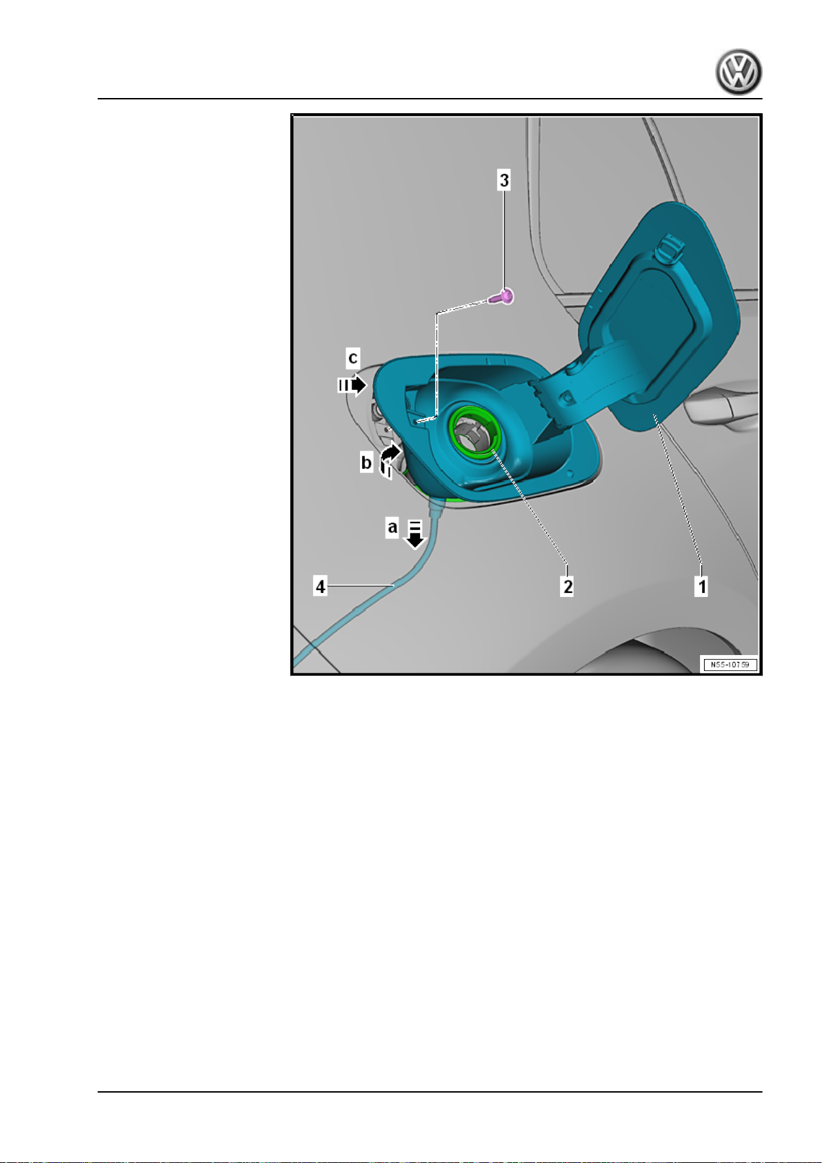
Golf 2015 ➤ , Golf Variant 2015 ➤
Body Exterior - Edition 02.2016
Installing
– Insert the water drain hose -4- through the opening in the fuel
filler door unit -1- and then pull it all the way through.
– Push the water drain hose -4- into the side panel in direction
of -arrow a-.
– Pivot the fuel filler door unit -1- in the side pane in direction of
-arrow b- and pull the boot over the filler neck -2-.
– If equipped, pull the fuel filler door unit boot over the reducing
agent filler neck.
– Push the fuel filler door unit completely into the side panel in
direction of -arrow c-.
3. Fuel Filler Door Unit 75
Page 84
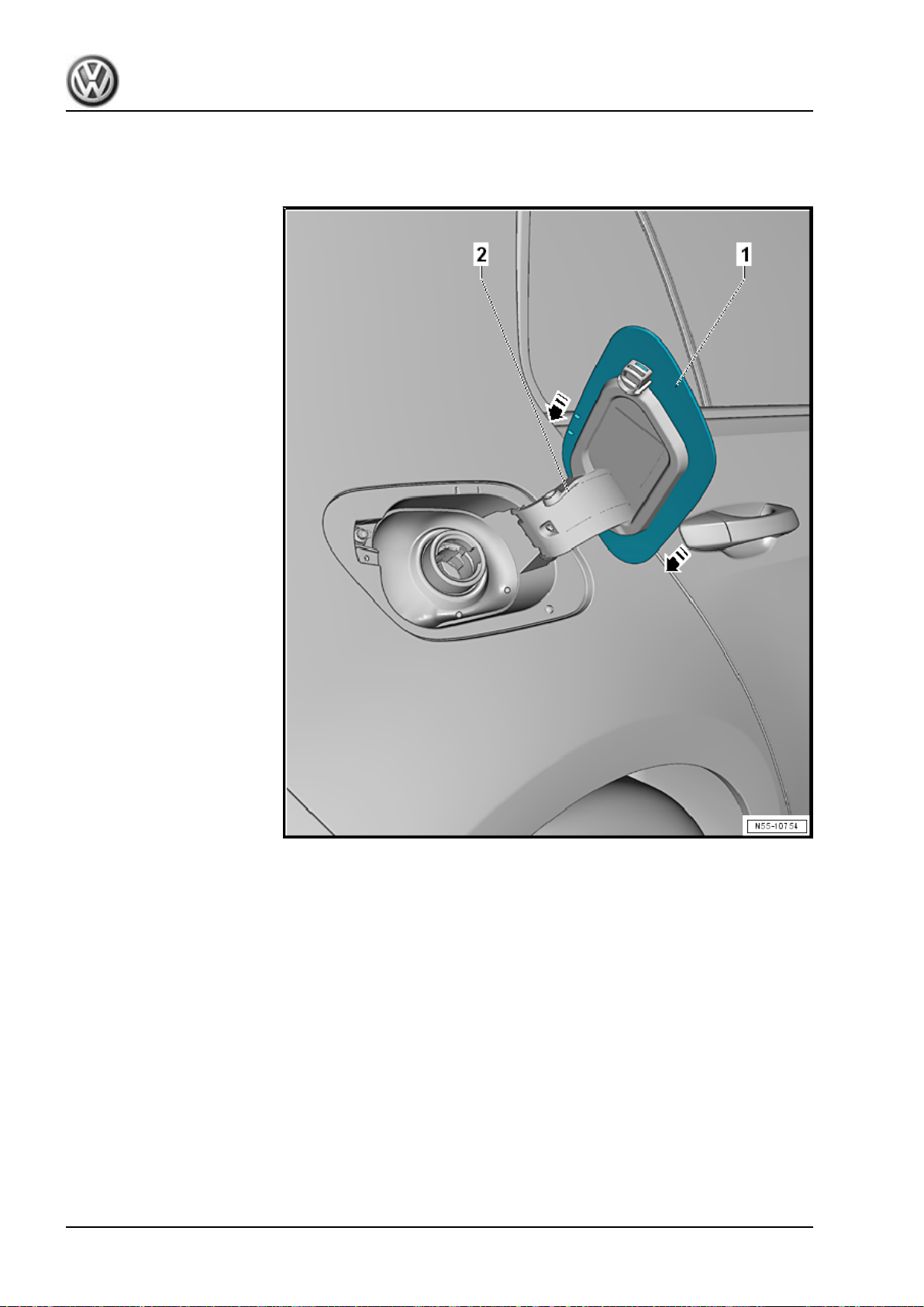
Golf 2015 ➤ , Golf Variant 2015 ➤
Body Exterior - Edition 02.2016
Tightening Specifications
3.3 Fuel Filler Door, Removing and Installing
Removing
– Push the fuel filler door -1- out of the fuel filler door unit re‐
tainers -2- in direction of -arrows-.
– Remove the fuel filler door.
Installing
– Place the fuel filler door -1- on the fuel filler door unit -2-.
– Push the fuel filler door into the fuel filler door unit retainers.
76 Rep. Gr.55 - Hood, Lids
Page 85
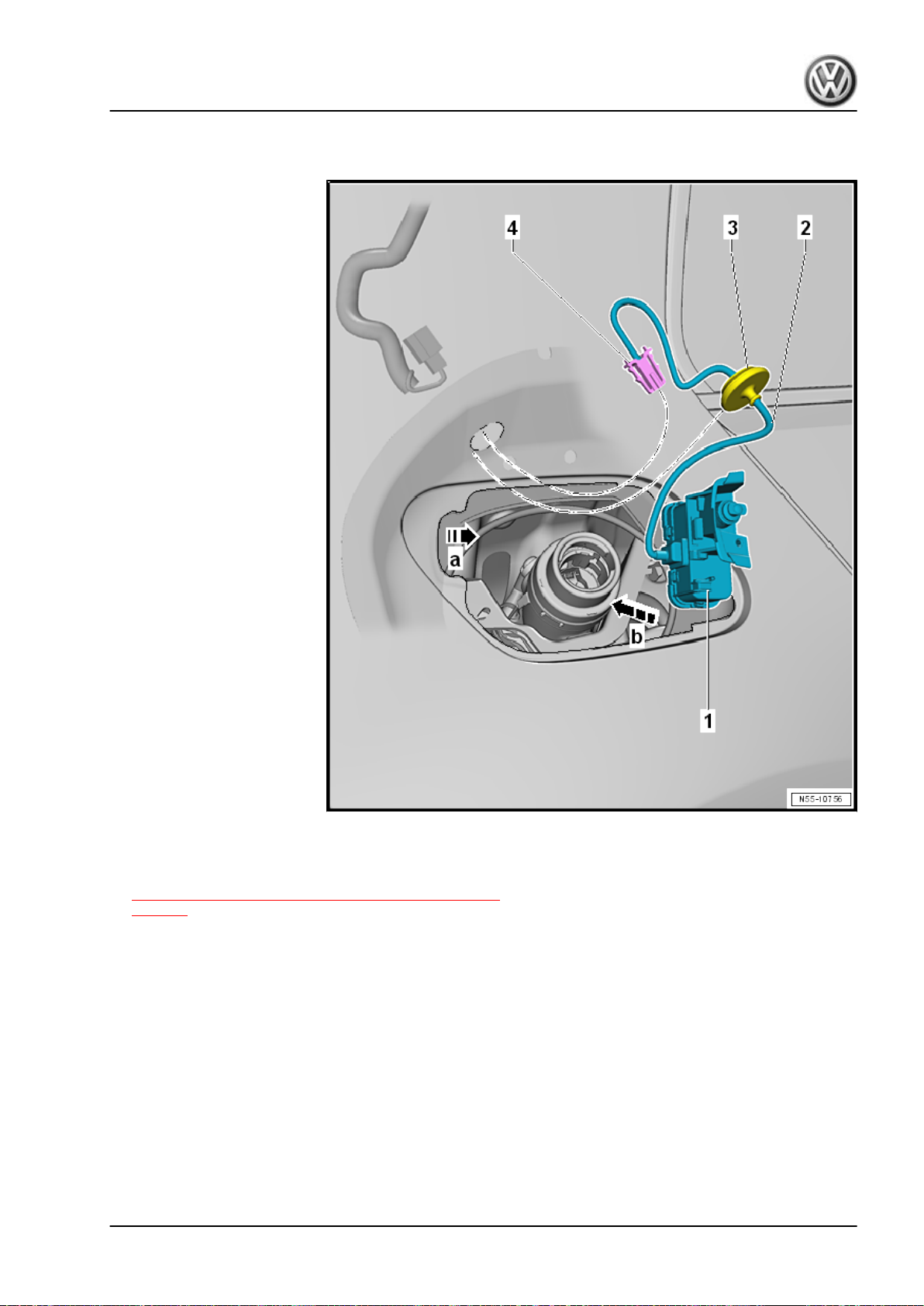
Golf 2015 ➤ , Golf Variant 2015 ➤
3.4 Adjusting Element, Removing and Installing
Body Exterior - Edition 02.2016
Removing
– Remove the fuel filler door unit. Refer to
⇒ “3.2 Fuel Filler Door Unit, Removing and Installing”,
page 74 .
– To reach the connector, remove the right luggage compart‐
ment side trim panel. Refer to ⇒ Body Interior; Rep. Gr. 70 ;
Luggage Compartment Trim Panels; Luggage Compartment
Side Trim Panel, Removing and Installing .
– Disconnect the connector -4-.
– Pull the adjusting element -1- out of the side panel in direction
of -arrow a-.
Installing
– Connect the connector -4-.
– Install the grommet -3- in the side panel.
– Push the adjusting element -1- in the side panel in direction of
-arrow b-.
3. Fuel Filler Door Unit 77
Page 86
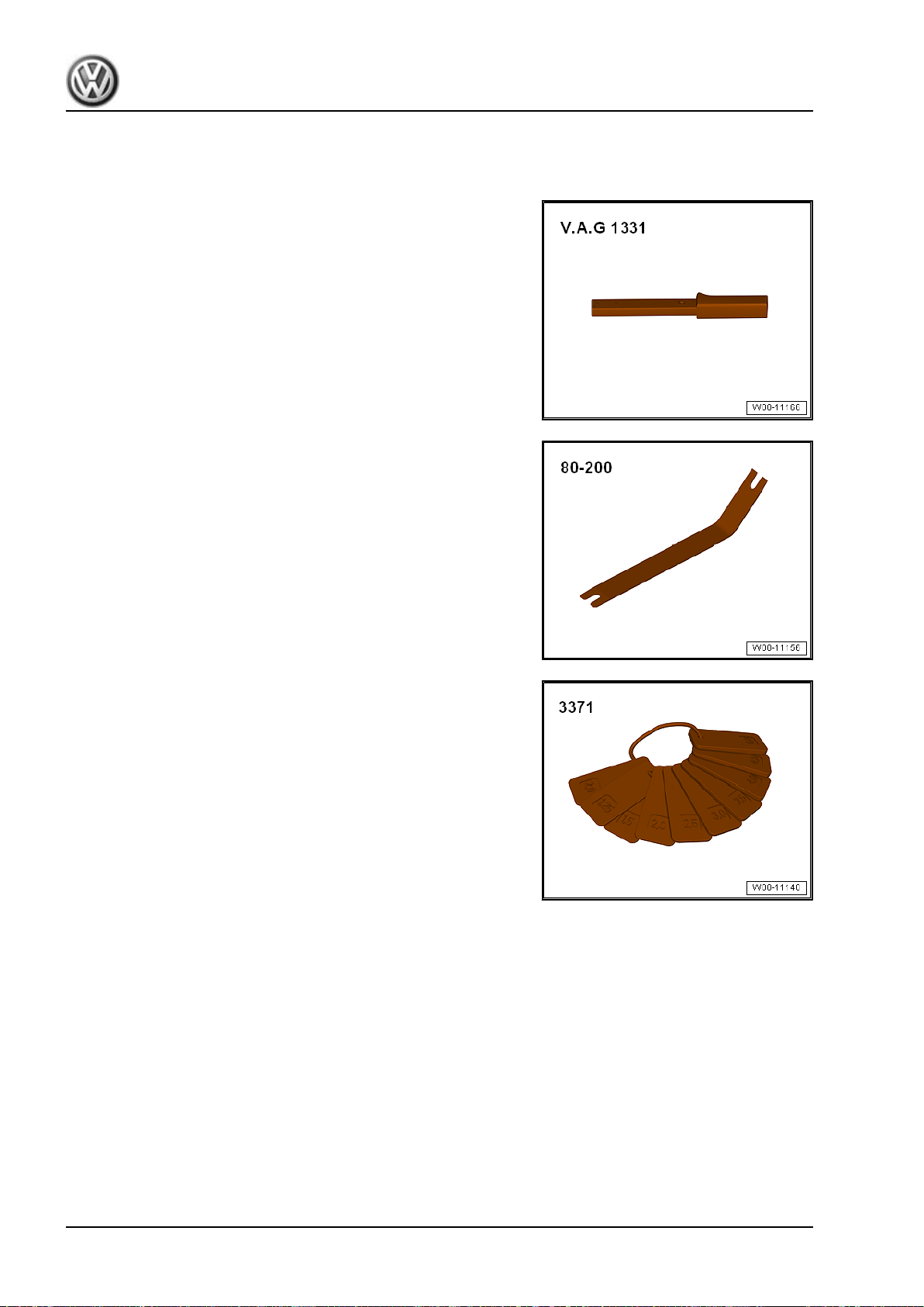
Golf 2015 ➤ , Golf Variant 2015 ➤
Body Exterior - Edition 02.2016
4 Special Tools
Special tools and workshop equipment required
♦ Torque Wrench 1331 5-50Nm - VAG1331-
♦ Pry Lever - 80-200-
♦ Gauge - Gap Adjustment - 3371-
78 Rep. Gr.55 - Hood, Lids
Page 87
Golf 2015 ➤ , Golf Variant 2015 ➤
Body Exterior - Edition 02.2016
57 – Front Doors, Central Locking System
1 Door
⇒ “1.1 Overview - Door”, page 79
⇒ “1.2 Inner Door Seal, Removing and Installing”, page 82
⇒ “1.3 Outer Door Seal, Removing and Installing”, page 84
⇒ “1.4 Door, Removing and Installing”, page 86
⇒ “1.5 Door, Adjusting”, page 89
⇒ “1.6 Catch, Adjusting”, page 91
⇒ “1.7 Door Arrester, Removing and Installing”, page 93
1.1 Overview - Door
Note
♦
The illustration shows the left side. The right side is identical.
♦
After replacing the A-pillar, the bolts -2 and 5- as well as -14 and 17- are to be tightened to another tightening
specification.
1. Door 79
Page 88
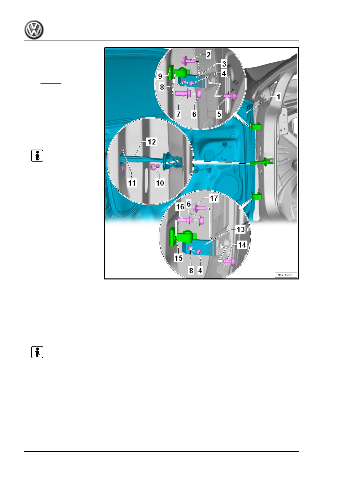
Golf 2015 ➤ , Golf Variant 2015 ➤
Body Exterior - Edition 02.2016
1 - Front Door
❑ Removing and instal‐
ling. Refer to
⇒ “1.4 Door, Removing
and Installing”,
page 86 .
❑ Adjusting. Refer to
⇒ “1.5 Door, Adjusting”,
page 89 .
2 - Bolt
❑ 50 Nm
❑ Loosening one time to
adjust the door is per‐
mitted. Always replace
afterward.
Note
♦
Another tightening specification
must be observed after replacing
the A-pillar.
♦
Tightening specification after re‐
placing the A-pillar: 20 Nm + 90°
3 - Door Hinge
❑ The hinge has two sec‐
tions. The upper and
lower section can be re‐
placed separately if nec‐
essary.
❑ The bolt -8- attaches the
hinge lower section to
the upper section.
4 - Cap
❑ For the bolt -8❑ Is not installed in all markets.
5 - Bolt
❑ 50 Nm
❑ Installed from the vehicle interior
❑ Loosening one time to adjust the door is permitted. Always replace afterward.
❑ The instrument panel is not removed for loosening and tightening.
❑ To remove and install, the instrument panel must be removed. Refer to ⇒ Body Interior; Rep. Gr. 70 ;
Instrument Panel; Instrument Panel, Removing and Installing .
Note
♦
Another tightening specification
must be observed after replacing
the A-pillar.
♦
Tightening specification after re‐
placing the A-pillar: 20 Nm + 90°
6 - Cap
❑ For bolts -7 and 16❑ Is not installed in all markets.
7 - Bolt
❑ 50 Nm
80 Rep. Gr.57 - Front Doors, Central Locking System
Page 89
Golf 2015 ➤ , Golf Variant 2015 ➤
Body Exterior - Edition 02.2016
❑ Loosening one time to adjust the door is permitted. Always replace afterward.
8 - Bolt
❑ 23 Nm
❑ Connects the upper hinge portion -9 or 15- to the lower hinge portion -3 or 13-.
9 - Door Hinge
❑ The hinge has two sections. The upper and lower section can be replaced separately if necessary.
❑ The bolt -8- attaches the upper section to the hinge lower section.
10 - Bolt
❑ 30 Nm
11 - Bolt
❑ 9 Nm
❑ Quantity: 2
12 - Door Arrester
❑ Removing and installing. Refer to ⇒ “1.7 Door Arrester, Removing and Installing”, page 93 .
13 - Door Hinge
❑ The hinge has two sections. The upper and lower section can be replaced separately if necessary.
❑ The bolt -8- attaches the hinge lower section to the upper section.
14 - Bolt
❑ 50 Nm
❑ Installed from the vehicle interior
❑ Loosening one time to adjust the door is permitted. Always replace afterward.
❑ The A-pillar lower trim must be removed in order remove and install. Refer to ⇒ Body Interior; Rep. Gr.
70 ; Passenger Compartment Trim; A-Pillar Trim Panel, Removing and Installing .
Note
♦
Another tightening specification
must be observed after replacing
the A-pillar.
♦
Tightening specification after re‐
placing the A-pillar: 20 Nm + 90°
15 - Door Hinge
❑ The hinge has two sections. The upper and lower section can be replaced separately if necessary.
❑ The bolt -8- attaches the upper section to the hinge lower section.
16 - Bolt
❑ 50 Nm
❑ Loosening one time to adjust the door is permitted. Always replace afterward.
17 - Bolt
❑ 50 Nm
❑ Loosening one time to adjust the door is permitted. Always replace afterward.
Note
♦
Another tightening specification
must be observed after replacing
the A-pillar.
♦
Tightening specification after re‐
placing the A-pillar: 20 Nm + 90°
1. Door 81
Page 90
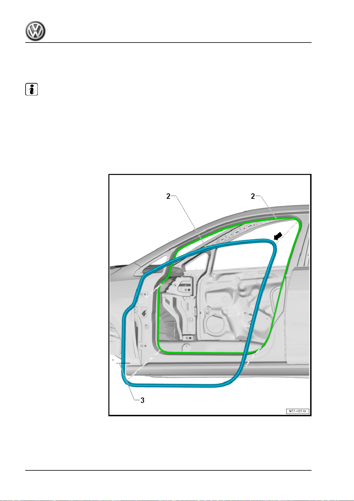
Golf 2015 ➤ , Golf Variant 2015 ➤
Body Exterior - Edition 02.2016
1.2 Inner Door Seal, Removing and Installing
The inner door seals are equipped at the factory with sealant,
applied to the door flange and then rolled on.
Note
♦
The sealant on the inside of the seal will spread when the seal is removed. The sides will bend up slightly.
If the seal is being reinstalled, the sealing strength and a secure fit are no longer guaranteed.
♦
For this reason, every seal that has been completely removed must be replaced with a so-called “hammerstroke seal”.
♦
For partially removed seals, the seal sides are pressed together before installing.
♦
The following describes the removal and installation of the left inner door seal. The right side is identical.
♦
For better illustration the front door is removed.
Removing
– Remove the sill panel strip. Refer to ⇒ Body Interior; Rep. Gr.
70 ; Passenger Compartment Trim; Sill Panel Strip, Removing
and Installing .
82 Rep. Gr.57 - Front Doors, Central Locking System
Page 91
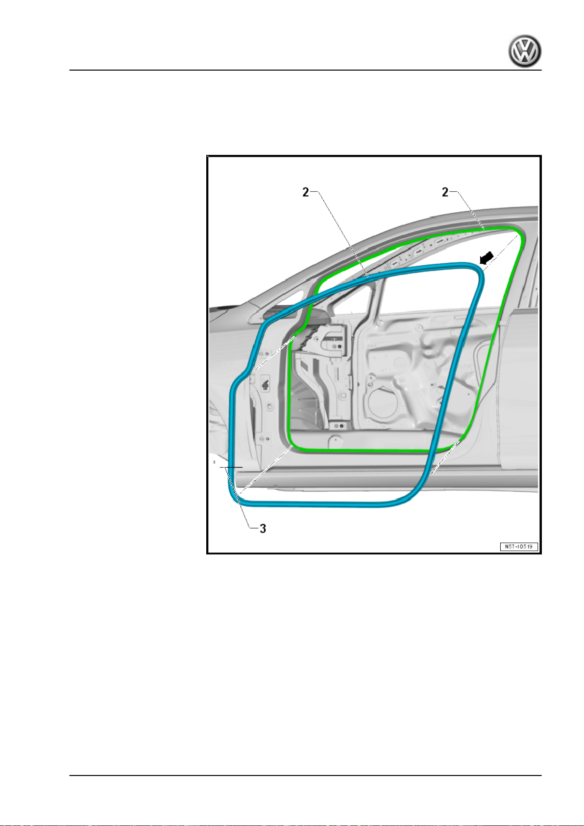
– To remove the inner door seal, remove the necessary pillar
trim panels. Refer to ⇒ Body Interior; Rep. Gr. 70 ; Passenger
Compartment Trim; Component Location Overview - Passen‐
ger Compartment Trim .
– Remove the inner door seal -2- from the body flange.
Golf 2015 ➤ , Golf Variant 2015 ➤
Body Exterior - Edition 02.2016
Installing
– Install the inner door seal -2- starting at the top of the door
opening -arrow-.
– Align the vulcanized point -3- above the lower hinge.
– Install the side trim panels. Refer to ⇒ Body Interior; Rep. Gr.
70 ; Passenger Compartment Trim; Component Location
Overview - Passenger Compartment Trim .
– Install the sill panel strip. Refer to ⇒ Body Interior; Rep. Gr.
70 ; Passenger Compartment Trim; Sill Panel Strip, Removing
and Installing .
1. Door 83
Page 92
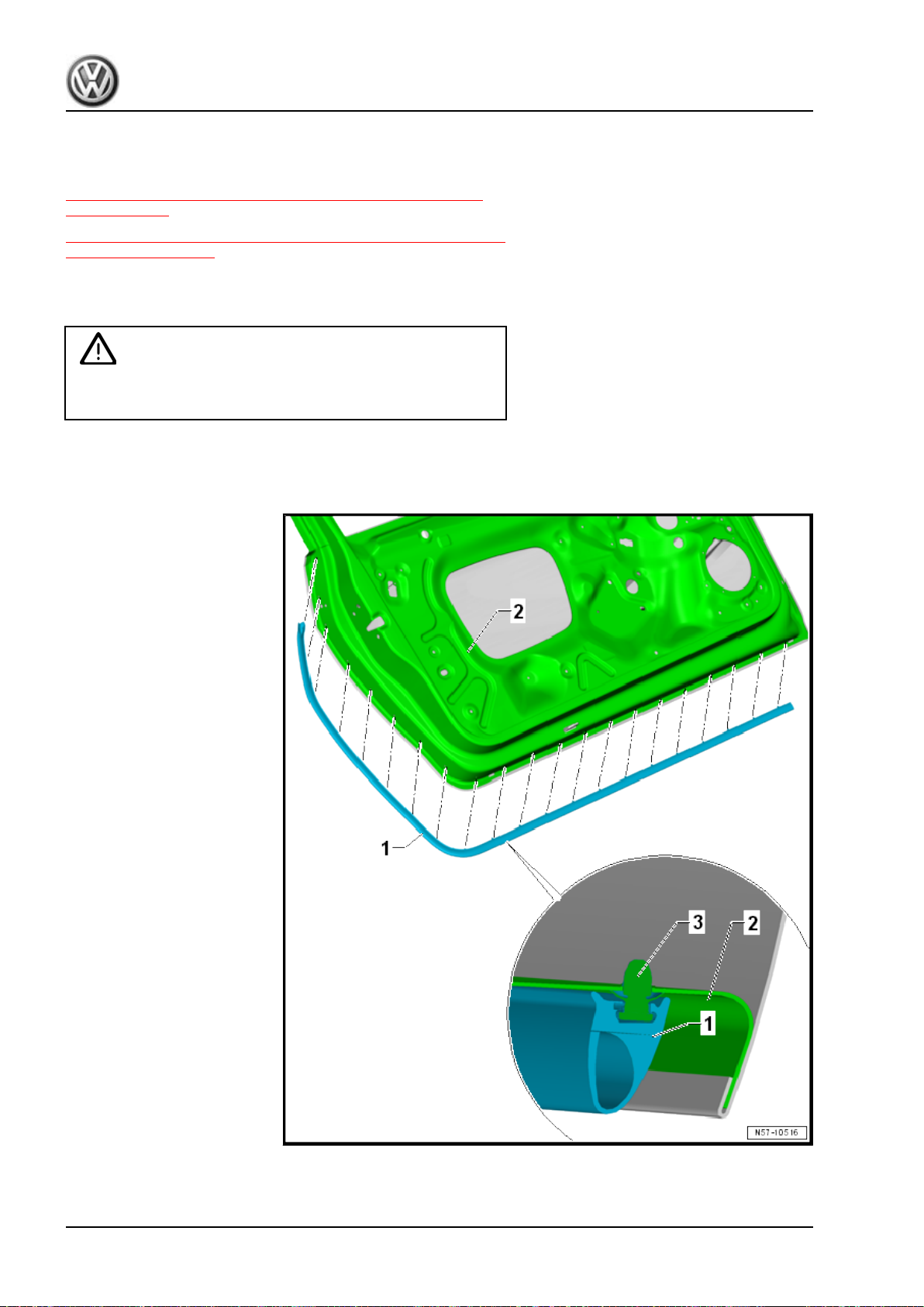
Golf 2015 ➤ , Golf Variant 2015 ➤
Body Exterior - Edition 02.2016
1.3 Outer Door Seal, Removing and Instal‐
ling
⇒ “1.3.1 Outer Door Seal, Removing and Installing, Sedan 2Door”, page 84
⇒ “1.3.2 Outer Door Seal, Removing and Installing, Sedan 4-Door
and Wagon”, page 85
1.3.1 Outer Door Seal, Removing and Instal‐
ling, Sedan 2-Door
Caution
This procedure contains mandatory replaceable parts. Refer
to component overview prior to starting procedure.
Mandatory Replacement Parts
♦ Circlips - Door Seal (Replace if damage)
84 Rep. Gr.57 - Front Doors, Central Locking System
Page 93
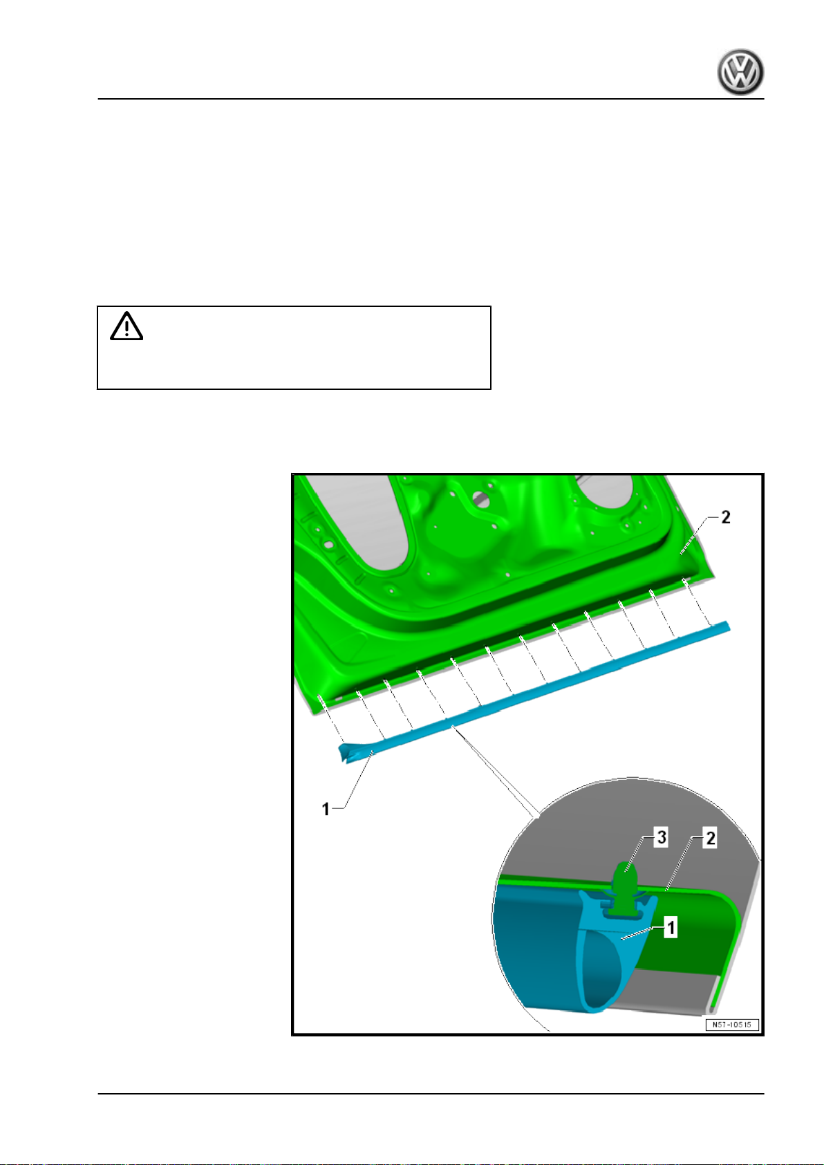
Removing
– Remove the door seal -1- with the clips -3- from the door -2-.
Installing
– Check the clips -3- for damage and replace if necessary.
– Press the door seal -1- with the clips -3- onto the door -2-.
The clips -3- must be pushed in until it stop.
1.3.2 Outer Door Seal, Removing and Instal‐
ling, Sedan 4-Door and Wagon
Caution
This procedure contains mandatory replaceable parts. Refer
to component overview prior to starting procedure.
Mandatory Replacement Parts
♦ Circlips - Door Seal (Replace if damage)
Golf 2015 ➤ , Golf Variant 2015 ➤
Body Exterior - Edition 02.2016
1. Door 85
Page 94
Golf 2015 ➤ , Golf Variant 2015 ➤
Body Exterior - Edition 02.2016
Removing
– Remove the door seal -1- with the clips -3- from the door -2-.
Installing
– Check the clips -3- for damage and replace if necessary.
– Press the door seal -1- with the clips -3- onto the door -2-.
The clips -3- must be pushed in until it stop.
1.4 Door, Removing and Installing
Special tools and workshop equipment required
♦ Wrench - Door Adjusting - 3320-
♦ Door Adjusting Wrench - Joint - 3320/1-
♦ Wrench - Door Adjusting - Box Wrench - 3320/2-
♦ Wrench - Door Adjusting - Box Wrench - 3320/3-
♦ Torque Wrench 1331 5-50Nm - VAG1331-
♦ Cylinder Head Bolt Socket - 3410-
♦ Gauge - Gap Adjustment - 3371-
♦ Trim Removal Wedge - 3409-
♦ Wedge Set - T10383-
Caution
This procedure contains mandatory replaceable parts. Refer
to component overview prior to starting procedure.
Mandatory Replacement Parts
♦ Bolts - Door Hinge to Body (Loosening one time to adjust the
door is permitted. Always replace afterward.)
♦ Bolt - Door Hinge to Door (Loosening one time to adjust the
door is permitted. Always replace afterward.)
Note
The following describes the removal and installation of the left front door. Removing and installing the right front
door is identical.
86 Rep. Gr.57 - Front Doors, Central Locking System
Page 95
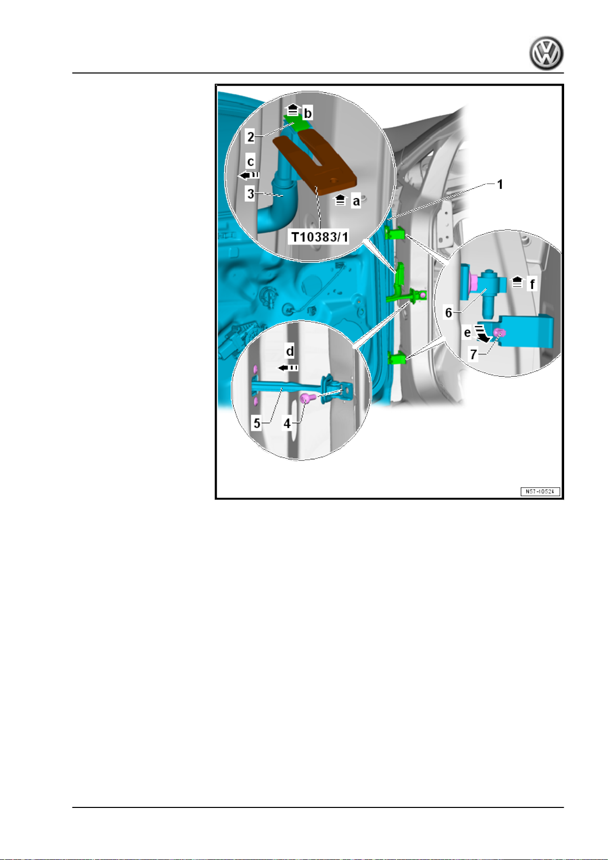
Golf 2015 ➤ , Golf Variant 2015 ➤
Body Exterior - Edition 02.2016
Removing
– Push the Wedge Set - T10383/1- between the boot -3- and the
locking mechanism in direction of -arrow a-.
– Push the locking mechanism -2- upward in direction of
-arrow b- using the Wedge Set - T10383/1- and disconnect the
connector -3- from the connector station in direction of
-arrow c-.
– Loosen the bolts -7- on the hinges.
– Remove the bolt -4- for the door strap -5-.
– Push the door strap -5- toward the inside in direction of
-arrow d-.
– Lift the front door -1- with the hinges -6- upward in direction of
-arrow f- out of the hinges.
1. Door 87
Page 96
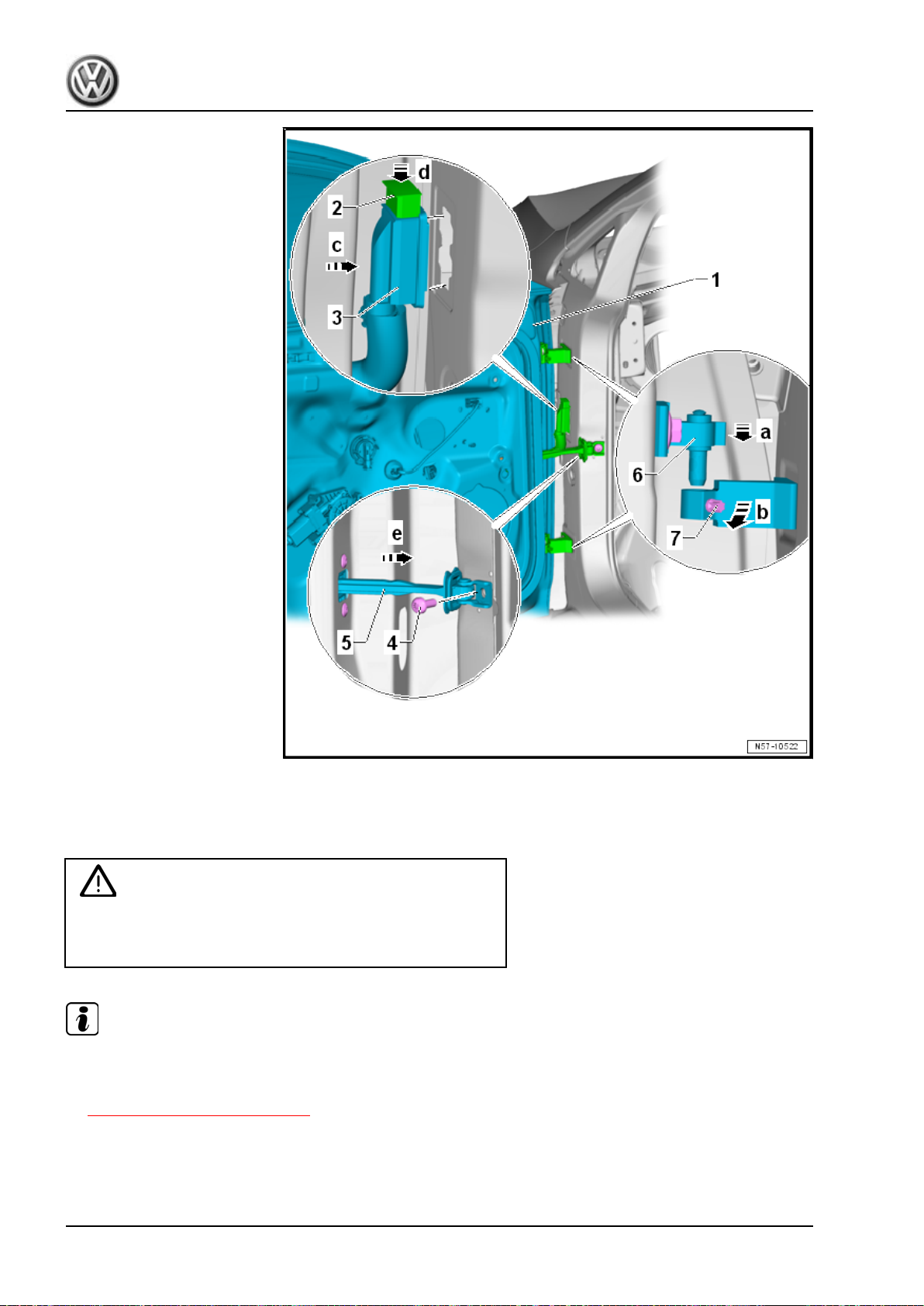
Golf 2015 ➤ , Golf Variant 2015 ➤
Body Exterior - Edition 02.2016
Installing
Install in reverse order of removal. Pay attention to the following
when installing:
Caution
The door strap bracket must be folded in toward the inside of
the vehicle (to prevent damaging the paint) before installing the
front door.
Note
The hinge arms must be flush with each other after engaging the front door.
– Adjust the front door -1-. Refer to
⇒ “1.5 Door, Adjusting”, page 89 .
– Pay attention the gap dimensions for the front door -1-. Refer
to ⇒ Body Repair; Rep. Gr. 00 ; Body Gap Dimensions; Center
Body .
88 Rep. Gr.57 - Front Doors, Central Locking System
Page 97
Tightening Specifications
Refer to ⇒ “1.1 Overview - Door”, page 79
1.5 Door, Adjusting
Special tools and workshop equipment required
♦ Wrench - Door Adjusting - 3320-
♦ Door Adjusting Wrench - Joint - 3320/1-
♦ Wrench - Door Adjusting - Box Wrench - 3320/2-
♦ Wrench - Door Adjusting - Box Wrench - 3320/3-
♦ Torque Wrench 1331 5-50Nm - VAG1331-
♦ Cylinder Head Bolt Socket - 3410-
♦ Gauge - Gap Adjustment - 3371-
♦ Trim Removal Wedge - 3409-
Caution
This procedure contains mandatory replaceable parts. Refer
to component overview prior to starting procedure.
Golf 2015 ➤ , Golf Variant 2015 ➤
Body Exterior - Edition 02.2016
Mandatory Replacement Parts
♦ Bolts - Door Hinge to Body (Loosening one time to adjust the
door is permitted. Always replace afterward.)
♦ Bolt - Door Hinge to Door (Loosening one time to adjust the
door is permitted. Always replace afterward.)
Note
♦
The following describes adjusting the left front door. Adjusting the right front door is identical.
♦
The vehicle must be on the ground in order to adjust the door.
♦
The front door is properly adjusted when there is an overall even gap dimension when closed. It is not too
far inward or outward. And the contours align.
♦
Checking the gap dimensions. Refer to ⇒ Body Repair; Rep. Gr. 00 ; Body Gap Dimensions; Center Body .
♦
Perform corrosion protection measures on the hinges and the bolts after assembling or adjusting.
1. Door 89
Page 98
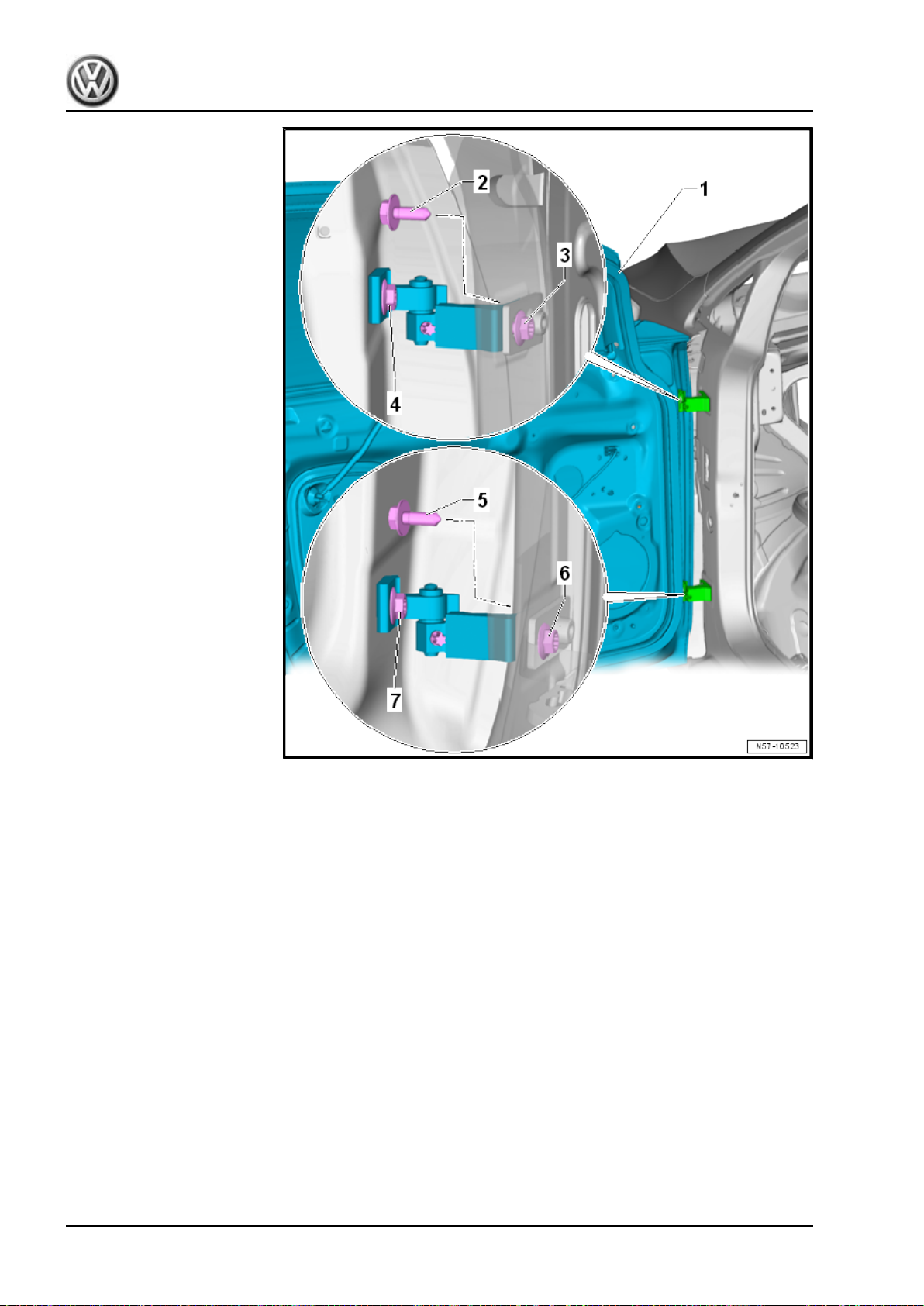
Golf 2015 ➤ , Golf Variant 2015 ➤
Body Exterior - Edition 02.2016
Gap Dimensions, Adjusting
For correct gap dimension adjustment, screws -2, 3, 5, and 6- at
the A-pillar must be loosened.
– For the bolt -3-, loosen and lower the driver side fuse box.
Refer to ⇒ Electrical Equipment; Rep. Gr. 97 ; Relay Carriers,
Fuse Panels and E-Boxes; Relay and Fuse Carrier Behind In‐
strument Panel on Driver Side, Removing and Installing .
– For the bolt -3-, the glove compartment on the front passenger
side must be removed. Refer to ⇒ Body Interior; Rep. Gr. 68 ;
Storage Compartments and Covers; Glove Compartment, Re‐
moving and Installing .
– Remove the A-pillar lower trim panel to access the bolt -6-.
Refer to ⇒ Body Interior; Rep. Gr. 70 ; Passenger Compart‐
ment Trim; A-Pillar Trim Panel, Removing and Installing .
Flush Dimension Adjustment
The bolts -4 and 7- must be loosened in order to correctly adjust
the flush dimension.
Use the Wrench - Door Adjusting - 3320- with the respective bit
for this.
90 Rep. Gr.57 - Front Doors, Central Locking System
Page 99
Golf 2015 ➤ , Golf Variant 2015 ➤
Body Exterior - Edition 02.2016
Note
Other measures, such as aligning the front door upward, are not effective. Later pressure will cause the front
door to sag again.
Adjust the catch. Refer to ⇒ “1.6 Catch, Adjusting”, page 91 .
Note
After replacing the A-pillar, the other tightening specification must be observed. Refer to
⇒ “1.1 Overview - Door”, page 79 .
Tightening Specifications
Refer to ⇒ “1.1 Overview - Door”, page 79
1.6 Catch, Adjusting
Special tools and workshop equipment required
♦ Torque Wrench 1331 5-50Nm - VAG1331-
Note
♦
The threaded plate -1- of the catch in the pillar is secured differently than before.
♦
The arch outside the threaded plate is welded securely to the pillar. The bars to the threaded plate are
malleable plastic.
♦
More force is needed to move the catch -2- when the bolts -3- are loose.
1. Door 91
Page 100
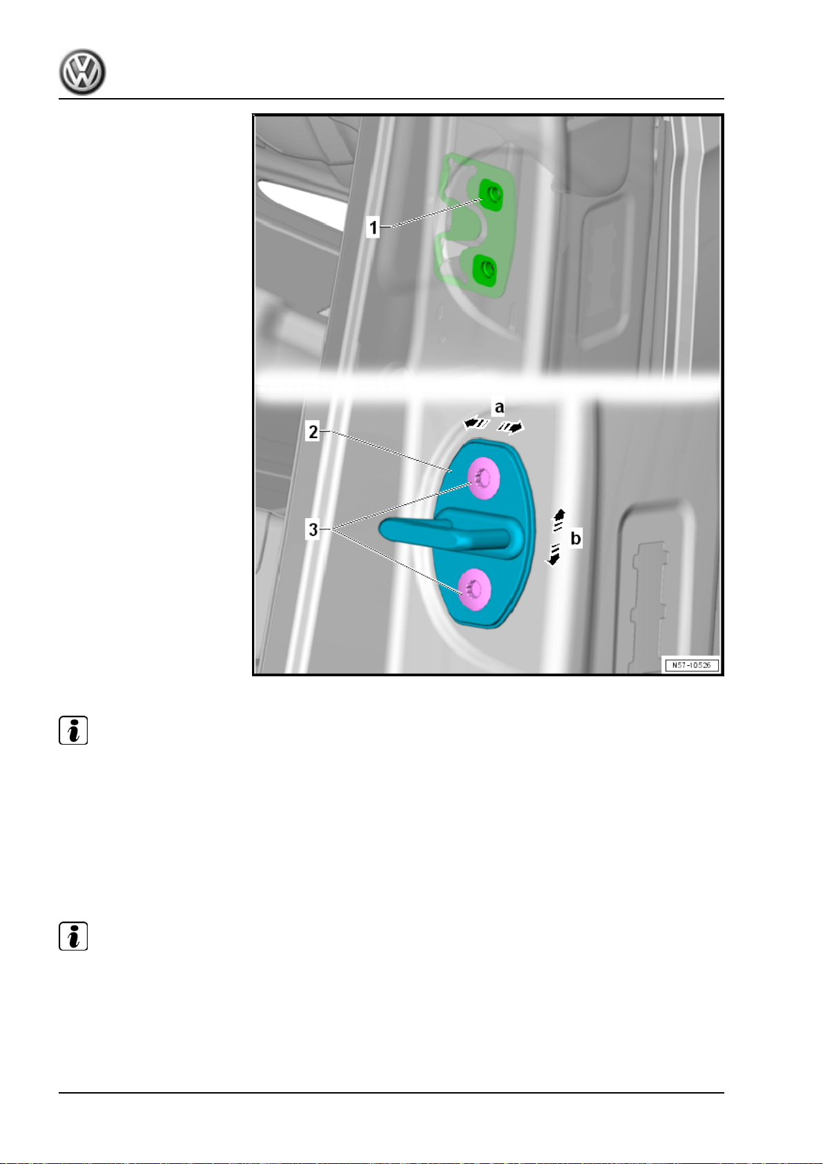
Golf 2015 ➤ , Golf Variant 2015 ➤
Body Exterior - Edition 02.2016
Note
♦
The following describes adjusting the left front door. Adjusting the right front door is identical.
♦
When closing, the front door must latch completely without additional force and it must not have any play.
♦
The front door must not be pushed up or down when adjusting the catch.
The alignment of the front door to the side panel or the rear door
can be adjusted via the catch in direction of -arrows a- and
-arrows b- (wind noise).
– Loosen the bolts -3- on the B-pillar to loosen the catch -2-.
Note
More force is needed to move the catch -2- when the bolts -3- are loose.
– Tighten the bolts -3- of the catch -2-.
92 Rep. Gr.57 - Front Doors, Central Locking System
 Loading...