

Page 1
Service Training
Self-study Programme 488
The Passat 2011
Page 2
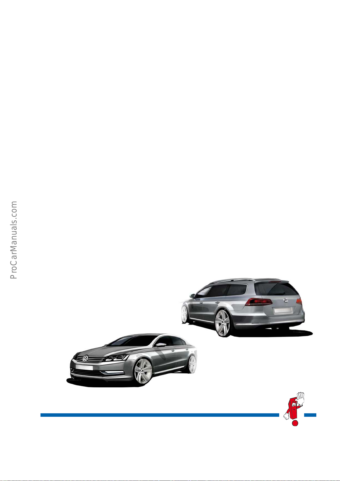
The Passat 2011
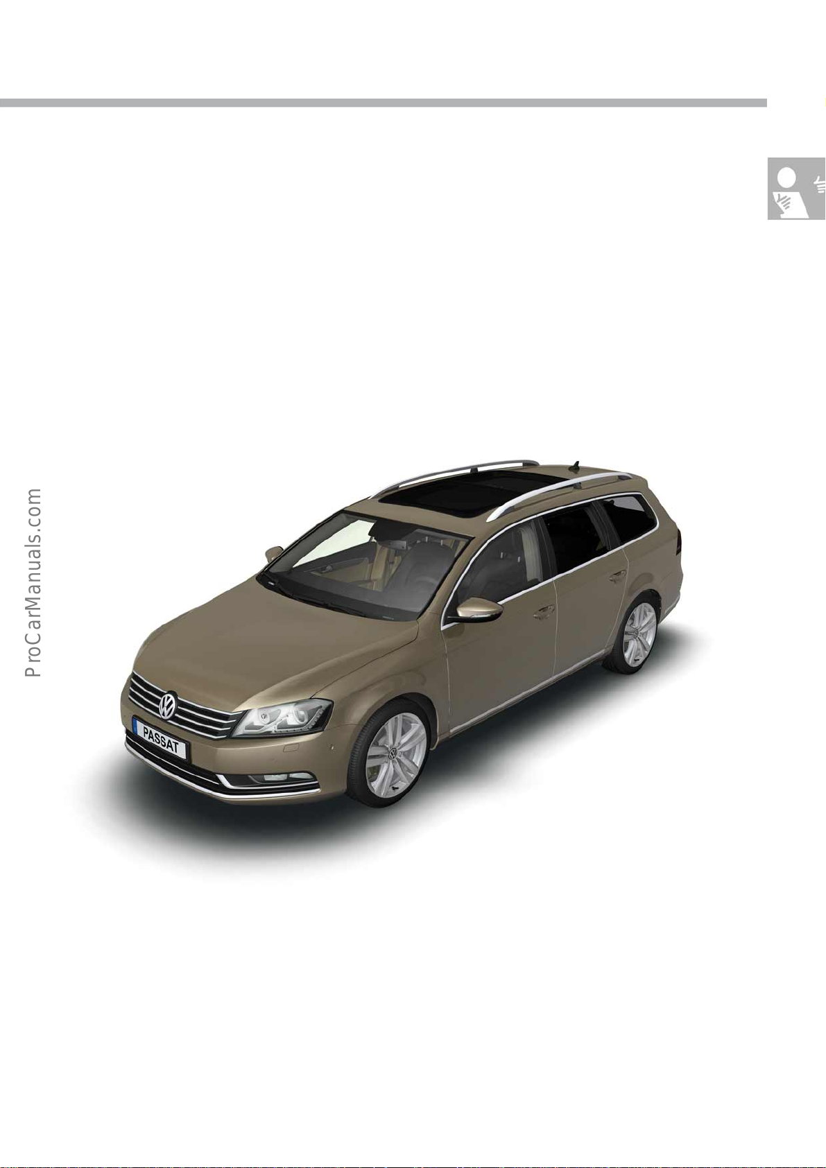
In its seventh generation, the new Passat has been perfected in terms of comfort, quality and safety attributes as
well as in the range of driver assistance systems offered.
Straight lines, clearly structured surfaces and dynamic proportions distinguish the design of the new generation
saloon and estate.
New experiences in comfort are achieved by the rear seat system that can be released from the luggage
compartment, a trailer hitch that folds out at the press of a button, noise insulating laminated safety glass for the
windscreen and front side windows and 2nd generation park assist steering system.
Highly efficient and eco-friendly TSI engines, TDI CR lightweight engines, a natural gas powered engine and an
engine of the newest generation that can be powered with up to 85% ethanol in the vehicle.
Engine downsizing, the start-stop system and regenerative braking facilitate a significant saving in fuel
consumption during operation.
The Front Assist system with automatic City Emergency Brake (braking function) and the Fatigue Detection System
are new and progressive functions in the area of safety.
With its high level of quality, the new Passat generation bridges a gap to the next highest vehicle category.
S488_045
S488_043
The self-study programme portrays the
design and function of new
developments.
The contents will not be updated.
For current testing, adjustment and repair
instructions, refer to the relevant service literature.
Caution
Note
2
Page 3
Contents
Introduction . . . . . . . . . . . . . . . . . . . . . . . . . . . . . . . . . . . . . . . . . . . . . . . . . . . . . .4
Body . . . . . . . . . . . . . . . . . . . . . . . . . . . . . . . . . . . . . . . . . . . . . . . . . . . . . . . . . . 10
Occupant protection . . . . . . . . . . . . . . . . . . . . . . . . . . . . . . . . . . . . . . . . . . . . . . 19
Engines . . . . . . . . . . . . . . . . . . . . . . . . . . . . . . . . . . . . . . . . . . . . . . . . . . . . . . . 20
Power transmission . . . . . . . . . . . . . . . . . . . . . . . . . . . . . . . . . . . . . . . . . . . . . .37
Running gear . . . . . . . . . . . . . . . . . . . . . . . . . . . . . . . . . . . . . . . . . . . . . . . . . . 40
Driver assist systems . . . . . . . . . . . . . . . . . . . . . . . . . . . . . . . . . . . . . . . . . . . . .44
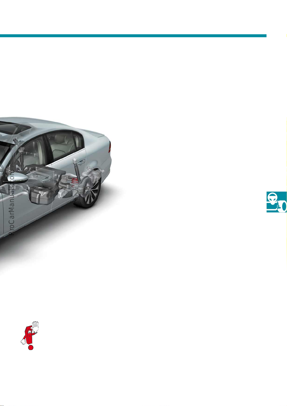
Electrical system . . . . . . . . . . . . . . . . . . . . . . . . . . . . . . . . . . . . . . . . . . . . . . . . . 51
Convenience electronics . . . . . . . . . . . . . . . . . . . . . . . . . . . . . . . . . . . . . . . . . . .56
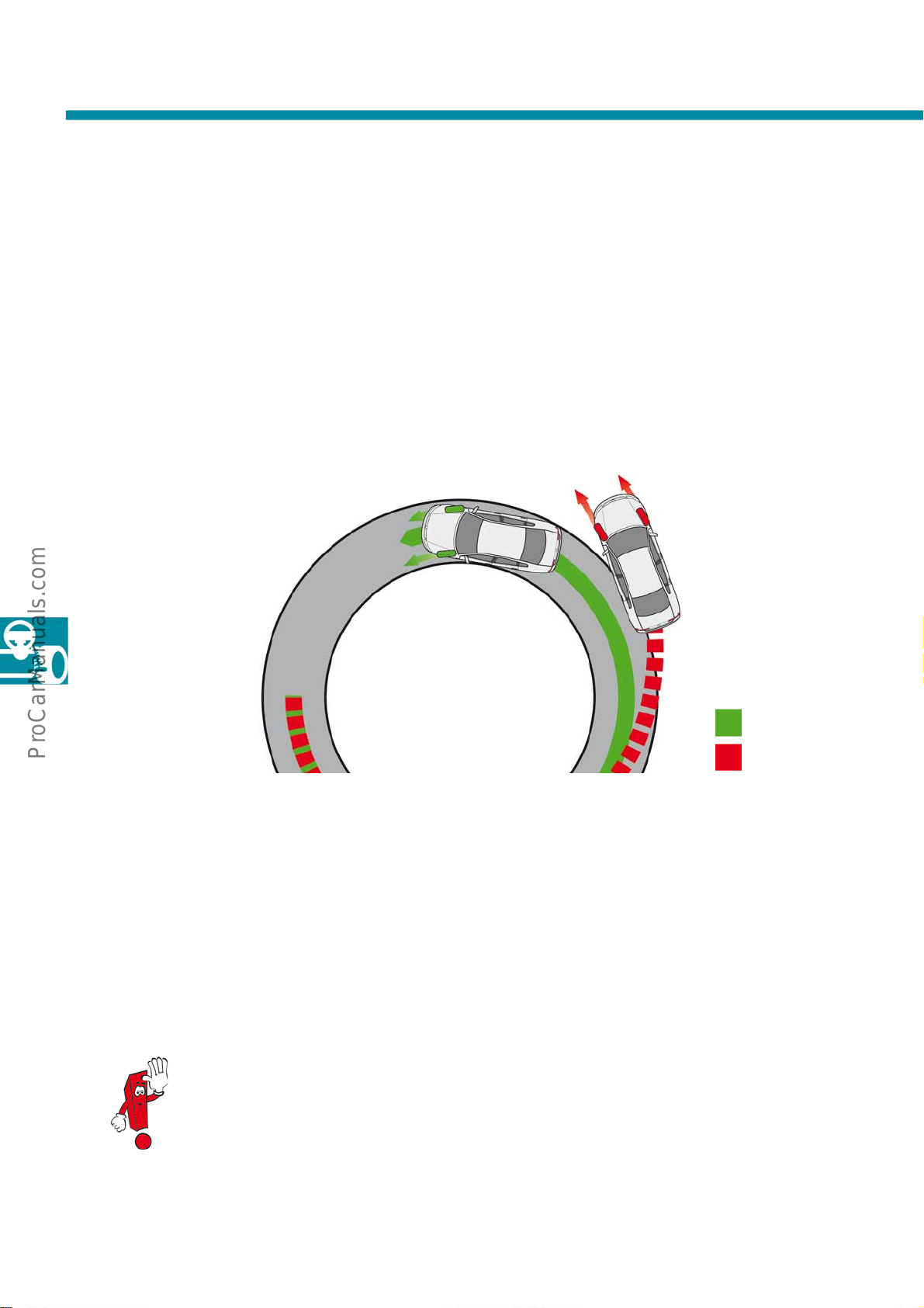
Radio, navigation and telephone . . . . . . . . . . . . . . . . . . . . . . . . . . . . . . . . . . .58
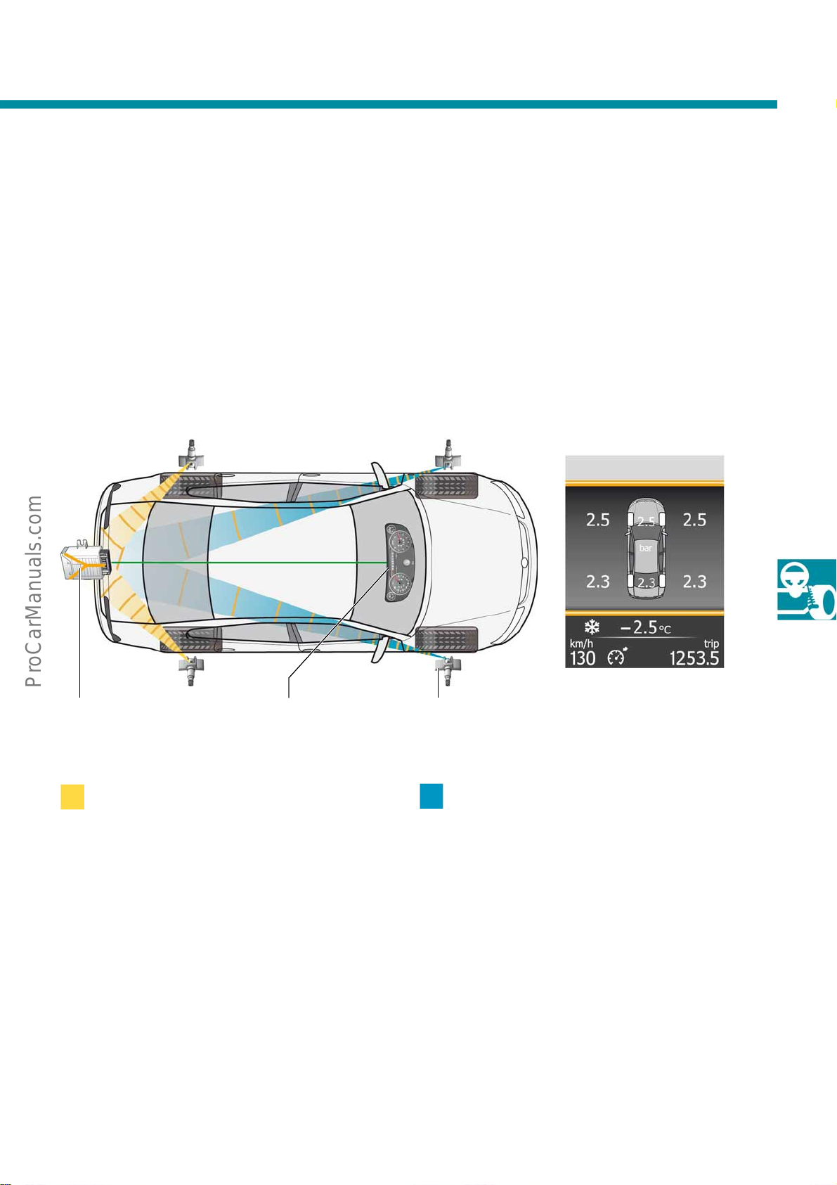
Heating and air conditioning . . . . . . . . . . . . . . . . . . . . . . . . . . . . . . . . . . . . . 68
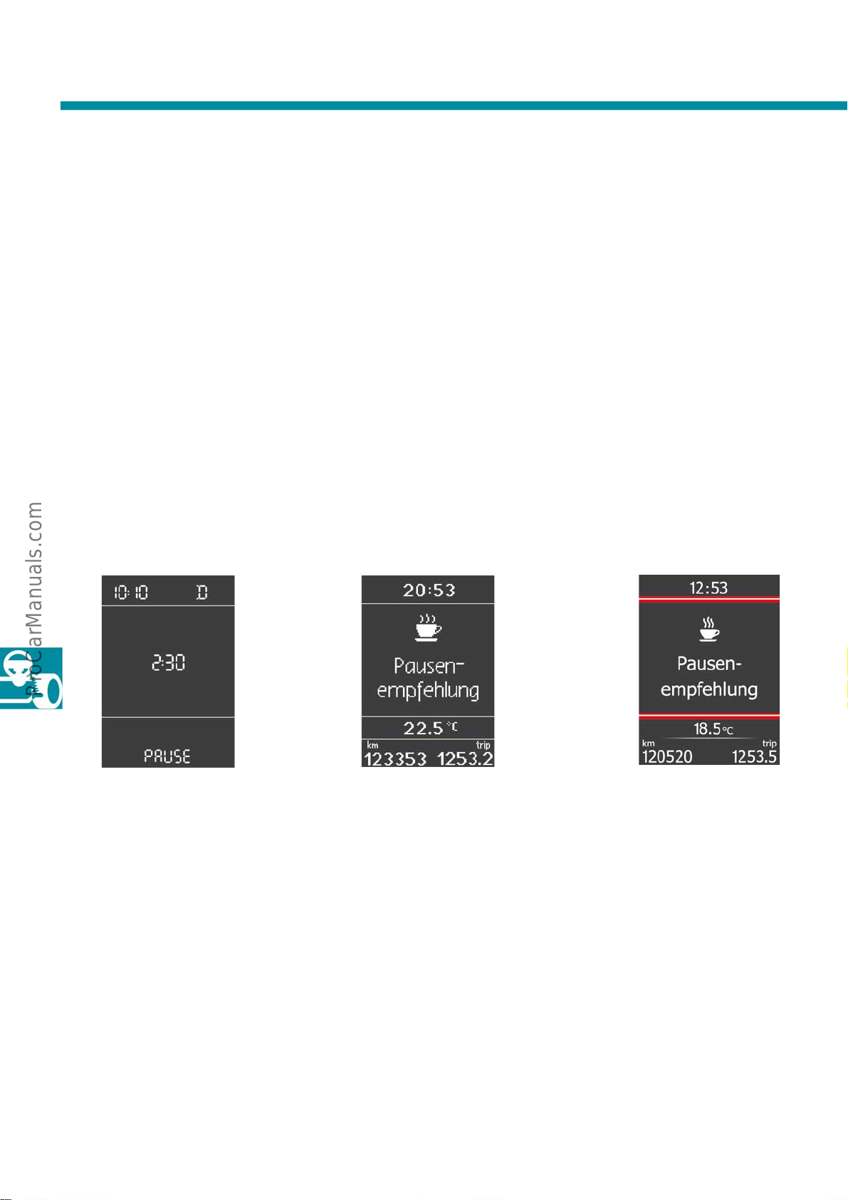
3
Page 4
Introduction
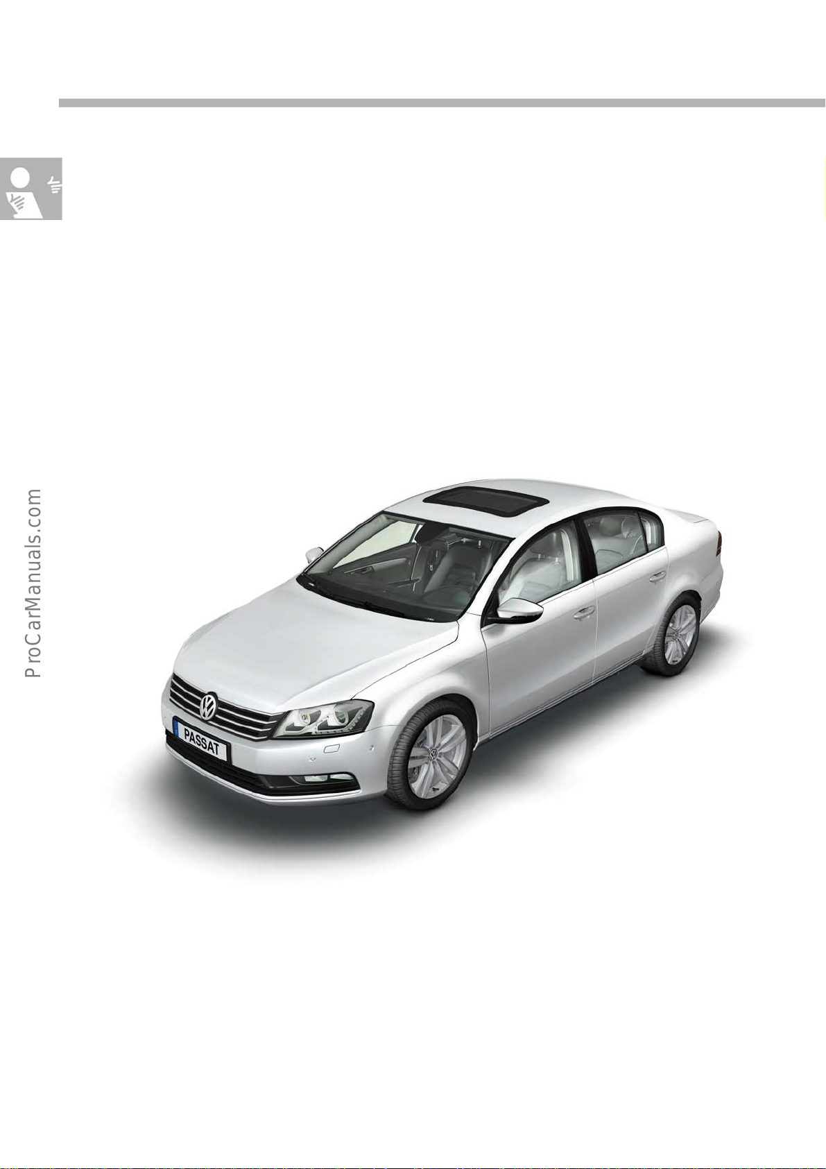
The Passat 2011
The overview indicates important series production and optional equipment features of the new Passat. The range
of options depends on the equipment lines: Trendline, Comfortline and Highline. Deviations may be possible
depending on the country.
● Bi-xenon headlights with dynamic light assist and
LED day driving lights, optional
● LED tail lights
● Main beam assist for halogen headlights,
optional
● Windscreen with acoustic laminated glass
● Heated windscreen, optional
● Front side windows with acoustic laminated glass,
optional
● Sliding/tilting electric solar roof, optional*
S488_007
● Luggage compartment lid with automatic
opening*
● Dual clutch gearbox with freewheel function,
optional
● Adaptive chassis control DCC, optional
* Only saloon
● Adaptive cruise control ACC
● Front Assist with City Emergency Brake
● 2nd generation park assist steering, optional
● Fatigue Detection System
4
Page 5
● "Premium" cellphone preparation, optional
● Air conditioning system
● Keyless access inc. start button, optional
● Panoramic sliding roof, optional**
● Electromechanical parking brake
● Electric opening and closing rear lid, optional**
S488_009
● Head restraints adjustable in X-direction
● Rear seat backrest with remote release
● Climate control seat with massage function,
optional
** Only estate
● Trailer hitch with folding feature and electric
release
● Luggage compartment management, optional**
● Convenient opening of luggage compartment
cover**
5
Page 6
Introduction
Technical d ata
Exterior dimensions and weights
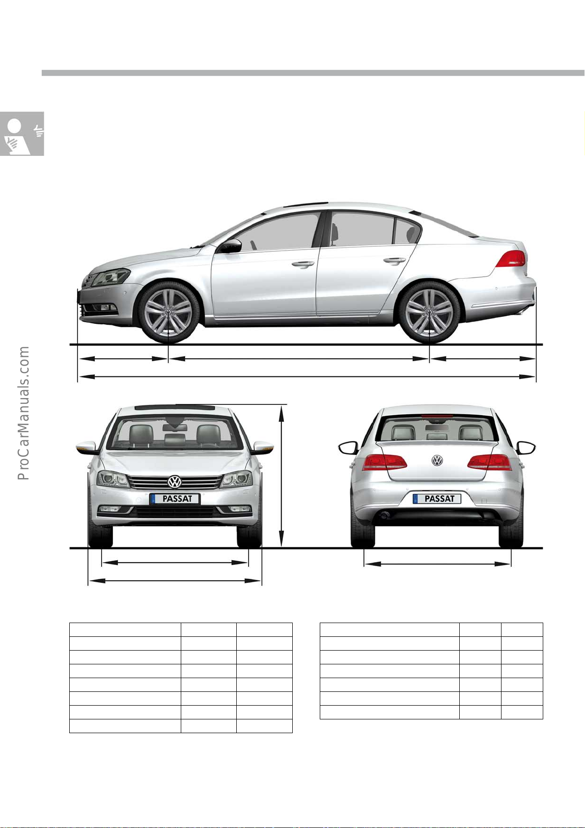
The details for the Passat saloon 2011 and the estate 2011 are based on a vehicle without driver, with standard
equipment, 1.4l 90 kW TSI engine and 205/55 R16 tyres.
S488_029
Exterior dimensions
Passat saloon 2006 2011
Length 4765mm 4769mm
Width 1820mm 1820mm
Height 1472mm 1470 mm
Wheelbase 2710mm 2712mm
Track width at front 1552mm 1552mm
Track width at rear 1551mm 1551mm
Turning circle 11.4m 11.4m
1552mm
1820mm
2712mm 1116mm941mm
4769 mm
1470mm
1551mm
Weights/further details
Passat saloon 2006 2011
Gross vehicle weight 1950kg 1990kg
Kerb weight 1391kg 1365kg
Max. trailer load, braked 1300kg 1400kg
Max. roof load 100kg 100kg
Tank capacity 70litres 70litres
Drag coefficient 0.295c
d
0.291c
d
6
Page 7
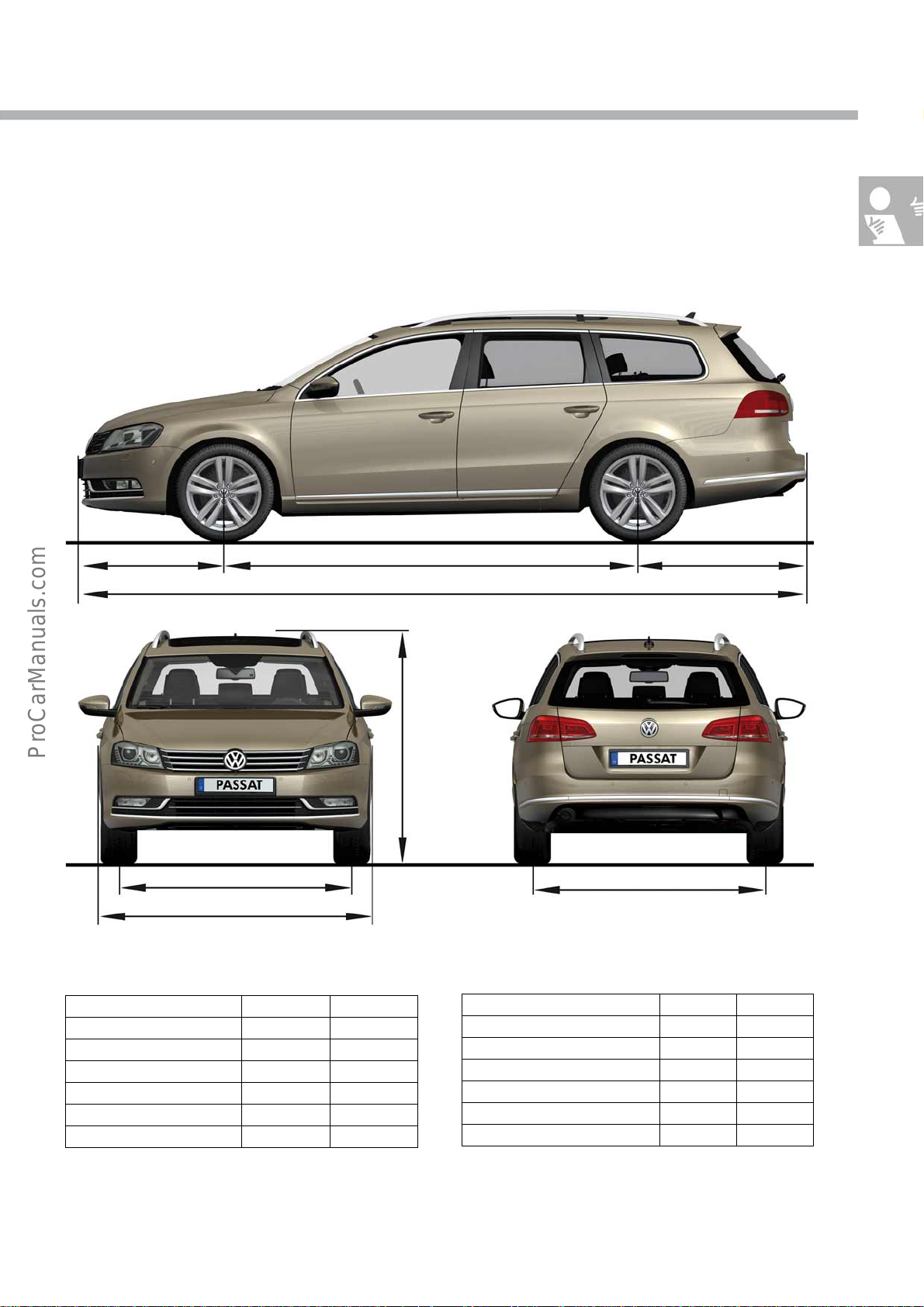
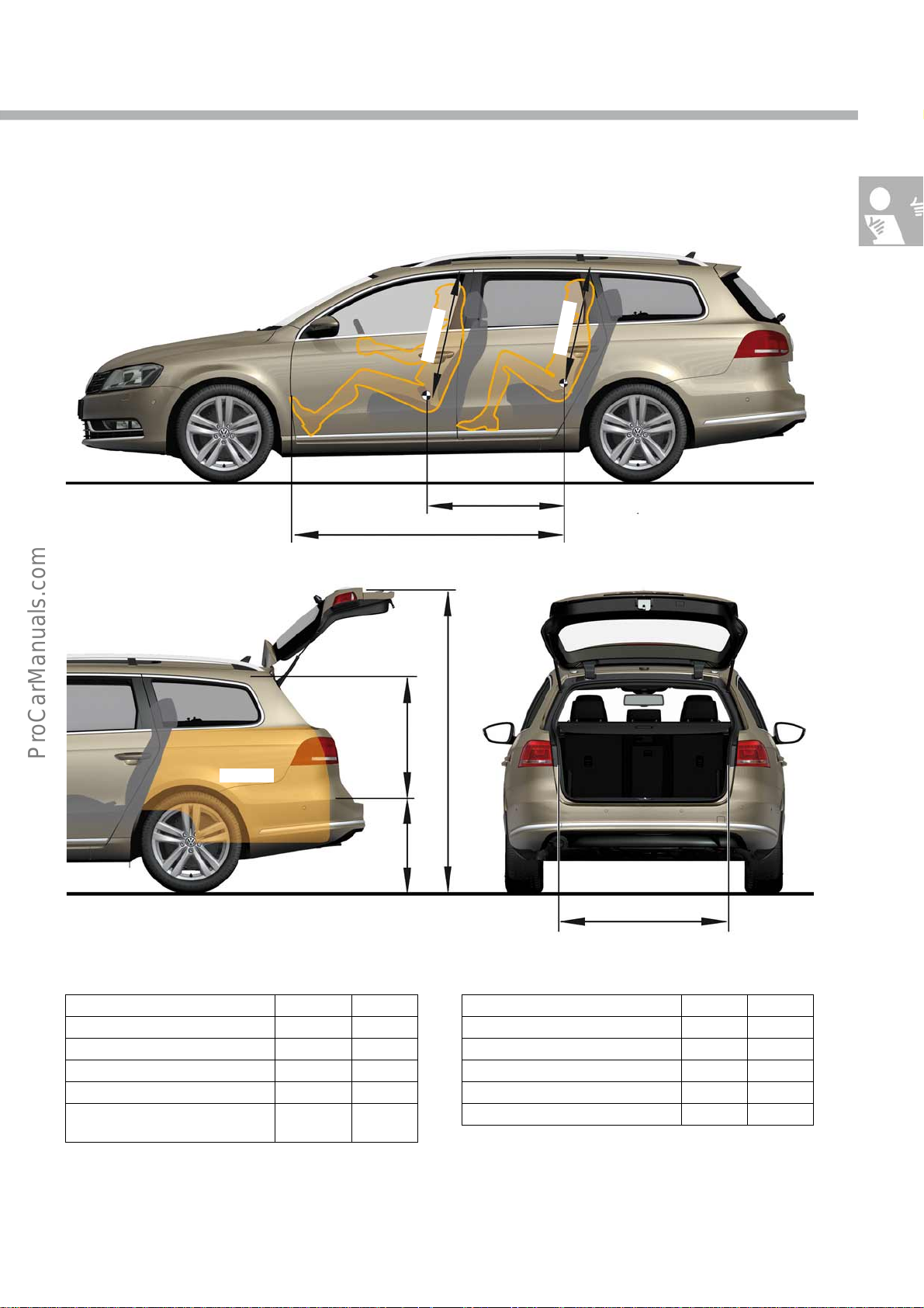
2712mm 1118mm941 mm
4771mm
S488_031
1552mm
1820mm
Exterior dimensions
Passat estate 2006 2011
Length 4774mm 4771 mm
Width 1820mm 1820 mm
Height (with roof rails) 1516mm 1516mm
Wheelbase 2710mm 2712mm
Track width at front 1552mm 1552mm
Track width at rear 1551mm 1551 mm
1516mm
1551mm
Weights/further details
Passat estate 2006 2011
Gross vehicle weight 1950kg 2070kg
Kerb weight 1391 kg 1402kg
Max. trailer load, braked 1300kg 1400 kg
Max. roof load 100kg 100kg
Tank capacity 70 litres 70 litres
Drag coefficient 0.304c
0.298c
d
d
7
Page 8
Introduction
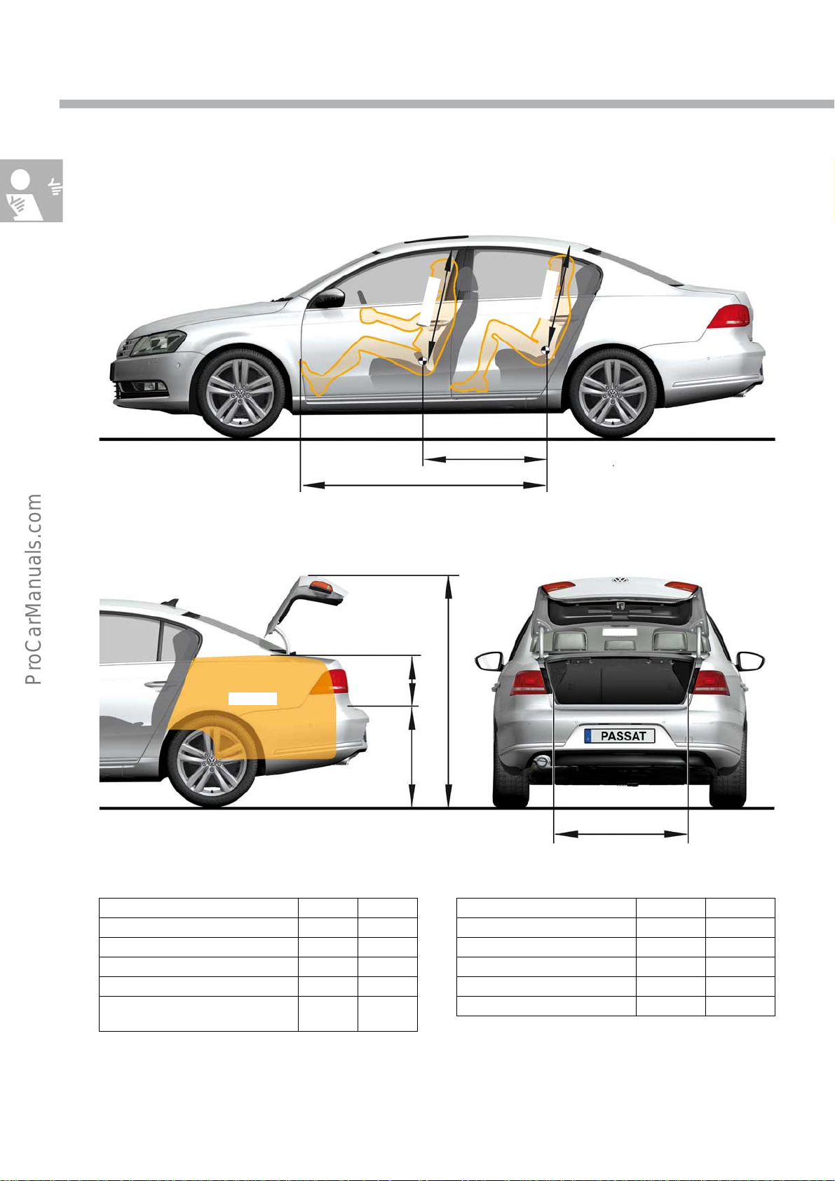
Interior dimensions and volumes
S488_033
565litres
m
m
2
2
0
1
1797mm
1766mm
859mm
mm
1
6
9
729mm 332mm
S488_037
1014mm
Interior dimensions and volumes
Passat saloon
Luggage compartment volume 565litres 565litres
Height of rear lid 1756mm 1766mm
Height of load sill 729mm 729mm
Cargo area height 332mm 332mm
Width of cargo area/wheel
housing
2006 2011
1014mm 1014mm
Passat saloon
Interior length 1797 mm 1797mm
Interior length 2nd seat row 859mm 859mm
Front headroom 1022mm 1022mm
Headroom 2nd seat row 961mm 961mm
Knee room 2nd seat row 91mm 76mm
2006 2011
8
Page 9
m
8m
1
0
1
0mm
8
9
S488_035
603litres
S488_039
859mm
1797mm
2027mm
624mm 719mm
1003mm
Interior dimensions and volumes
Passat estate
Luggage compartment volume 603litres 603litres
Height of rear lid 2058mm 2027mm
Height of load sill 624mm 624mm
Cargo area height 719mm 719mm
Width of cargo area at wheel
housing
2006 2011
1000mm 1003 mm
Passat estate
Interior length
Interior length 2nd seat row 859mm 859mm
Front headroom 1018mm 1018mm
Headroom 2nd seat row 980mm 980mm
Knee room 2nd seat row 91mm 76mm
2006 2011
1797mm 1797 mm
9
Page 10
Body
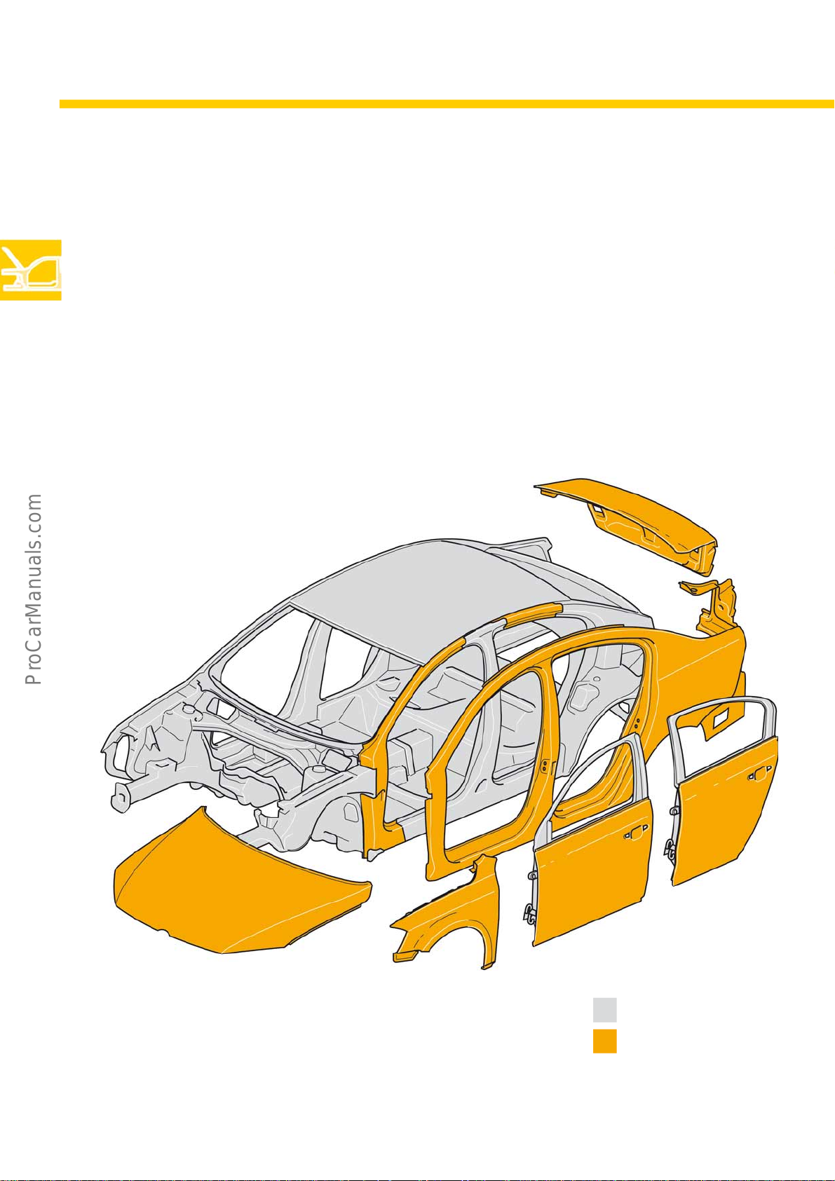
Body structure
The main aim during development of the body was to increase the body strength whilst, at the same time, reducing
weight. The bodies of the new Passat saloon and Passat estate are the same as the tried and tested 2006 model
series and have been further improved.
Scope of modifications to Passat saloon
● Bonnet
● Rear lid
● Wings
● Outer skin of doors
● Side panel
● A-pillar and door frame
● Rear panel
10
S488_032
Key
Carried over
New
Page 11
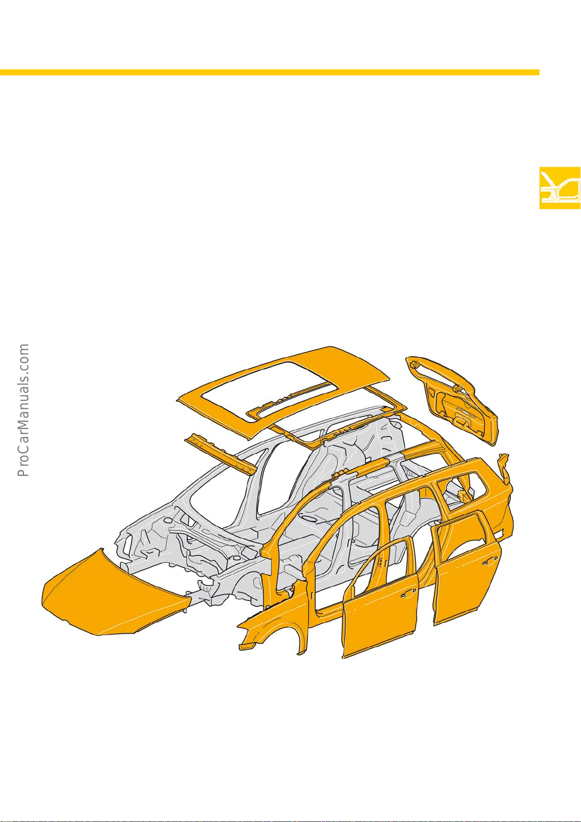
Scope of modifications to Passat estate
● Bonnet
● Rear lid
● Wings
● Doors
● Roof
● Side panel
● A-pillar and door frame
● D-pillar
● Rear panel
S488_030
11
Page 12
Body
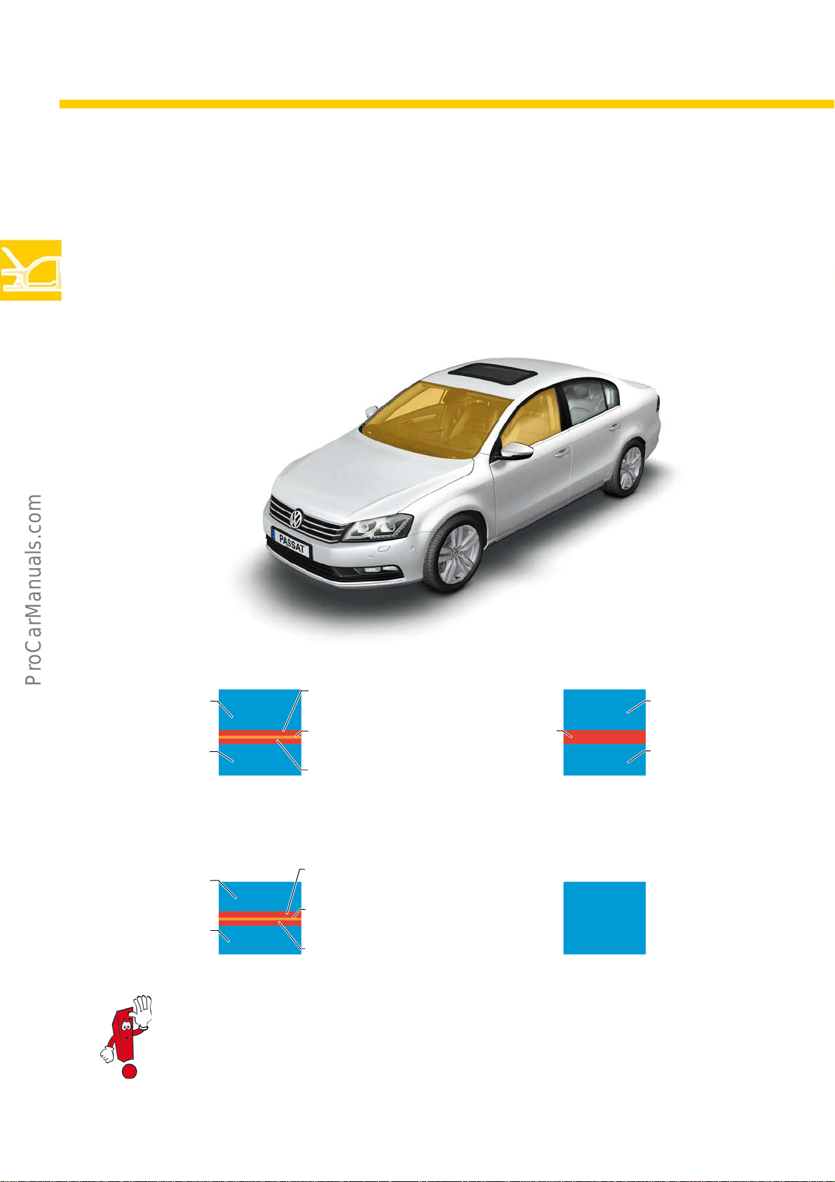
Windscreen with acoustic laminated glass
The windscreen in the Passat 2011 features acoustic laminated glass as standard. Furthermore, the windows in the
front doors are also available as an option with acoustic laminated glass. The use of acoustic PVB in the door
windows makes it possible to achieve a noise reduction of approx. 2-4 dB in the interior. Furthermore, a heated
windscreen can be ordered for the first time in the Passat in conjunction with heat reflective glass.
Windscreen with acoustic laminated glass Conventional windscreen
Outer glass
(2.1mm)
Inner glass
(1. 6mm)
Door window (TSG) with acoustic glass Standard door window (safety glass)
Outer glass
1.6mm)
Inner glass
(1. 6mm)
S488_036
S488_044
PVB film
(0.33mm)
Acoustic PVB film
(0.1mm)
PVB film
(0.33mm)
PVB film
(0.33mm)
Acoustic PVB film
(0.1mm)
PVB film
(0.33mm)
PVB film
(0.76mm)
Safety glass
(3.85mm)
S488_041
Outer glass
(2.1mm)
Inner glass
(1.6mm)
S488_034
S488_038
12
Compared with conventional door windows, there is a change to the software in the door control unit
on vehicles with acoustic door windows, and the window retainer in the door is also different. This
must be taken account of in the event of retroinstallation and repairs.
Page 13
The luggage compartment
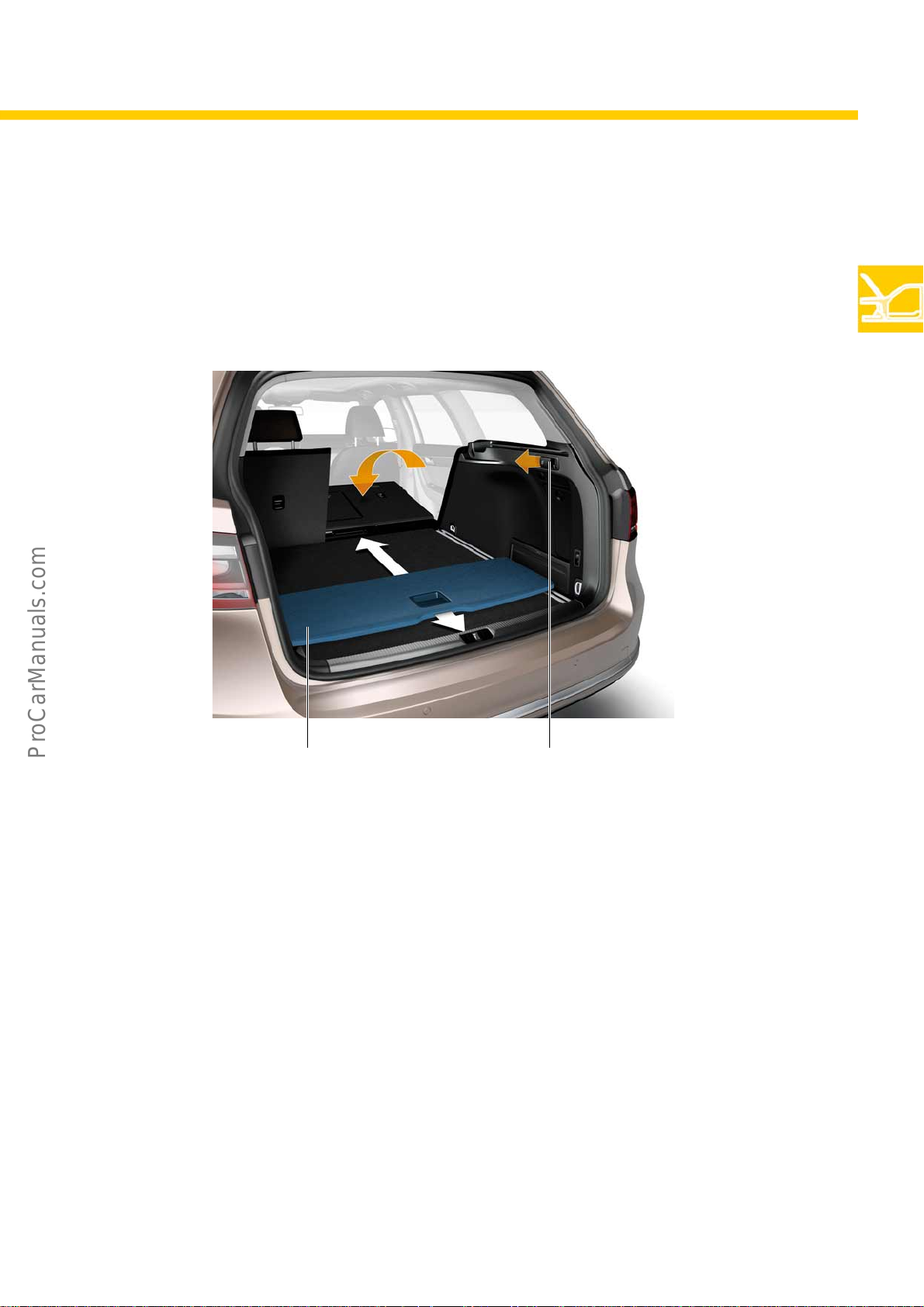
In the Passat estate, the following special features should be noted:
● the additional partition
● the sliding cargo floor
Sliding cargo floor
● Variable stowage space
● Different locking positions possible
● Removable cargo floor
● Withstands up to 100kg
S488_047
Cargo floor Remote release
Remote release of
rear seat backrest
The new remote release of the rear seat backrest
makes release possible from the luggage
compartment. The function is a standard feature from
the Trendline equipment level.
Cargo floor position
In the saloon and estate model, the rear bench seat
has a 60/40 split folding backrest.
13
Page 14
Body
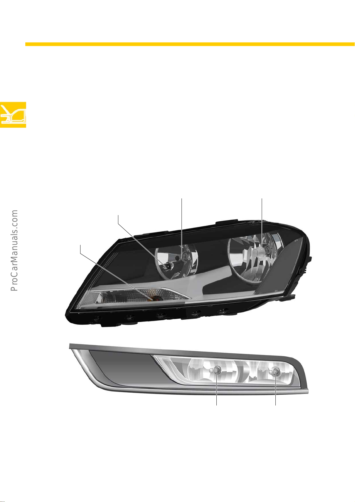
Halogen headlights
On this headlight module, the dipped beam and main beam are designed as separate H7 headlights. The side light
is integrated into the dipped beam headlight.
Dynamic light assist is not available for this module. As an option, the main beam assist function is available in
conjunction with halogen headlights.
Dipped beam, H7 (55W) Main beam, H7 (55W)
Turn s i gnal ( 2 4W)
Side light (5W)
S488_013
14
S488_064
Light module in bumper
In conjunction with H7 headlights, the cornering, fog
and day driving lights feature two separate bulbs.
Day driving light (21W) Fog and cornering light
(H8, 35W)
Page 15
Xenon headlights with LED
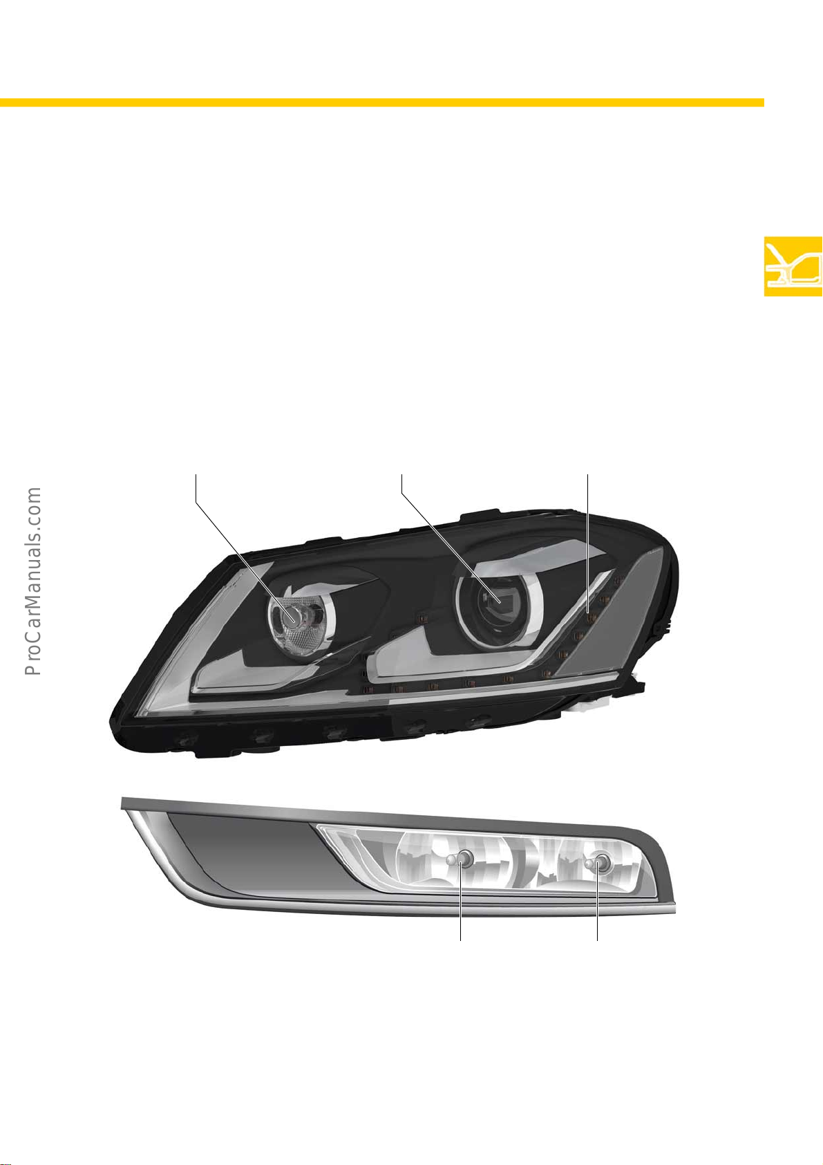
On this headlight unit, the dipped beam and main beam are integrated into the xenon module (D3S 35W). It
features LED daytime running lights and side light. Fifteen individual LEDs are located around the xenon module.
The amount of power drawn by the day driving lights is reduced to approx. 30watts compared with approx. 140 to
180watts on daytime headlights with dipped beam activated.
The xenon headlight always comes with the dynamic cornering light. Dynamic light assist (DLA) is available as an
option. Main beam assist cannot be combined with the xenon headlight.
Turn s ig n al ( 2 4W )
Dipped beam and main beam,
xenon (D3S 35W)
Daytime runing light and side light
(15 LEDs with total 30W)
S488_011
S488_064
Light module in bumper
In conjunction with xenon headlights, the cornering
and fog lights feature two separate bulbs.
Fog light (35W)Cornering light (35W)
15
Page 16
Body
Tail l ights
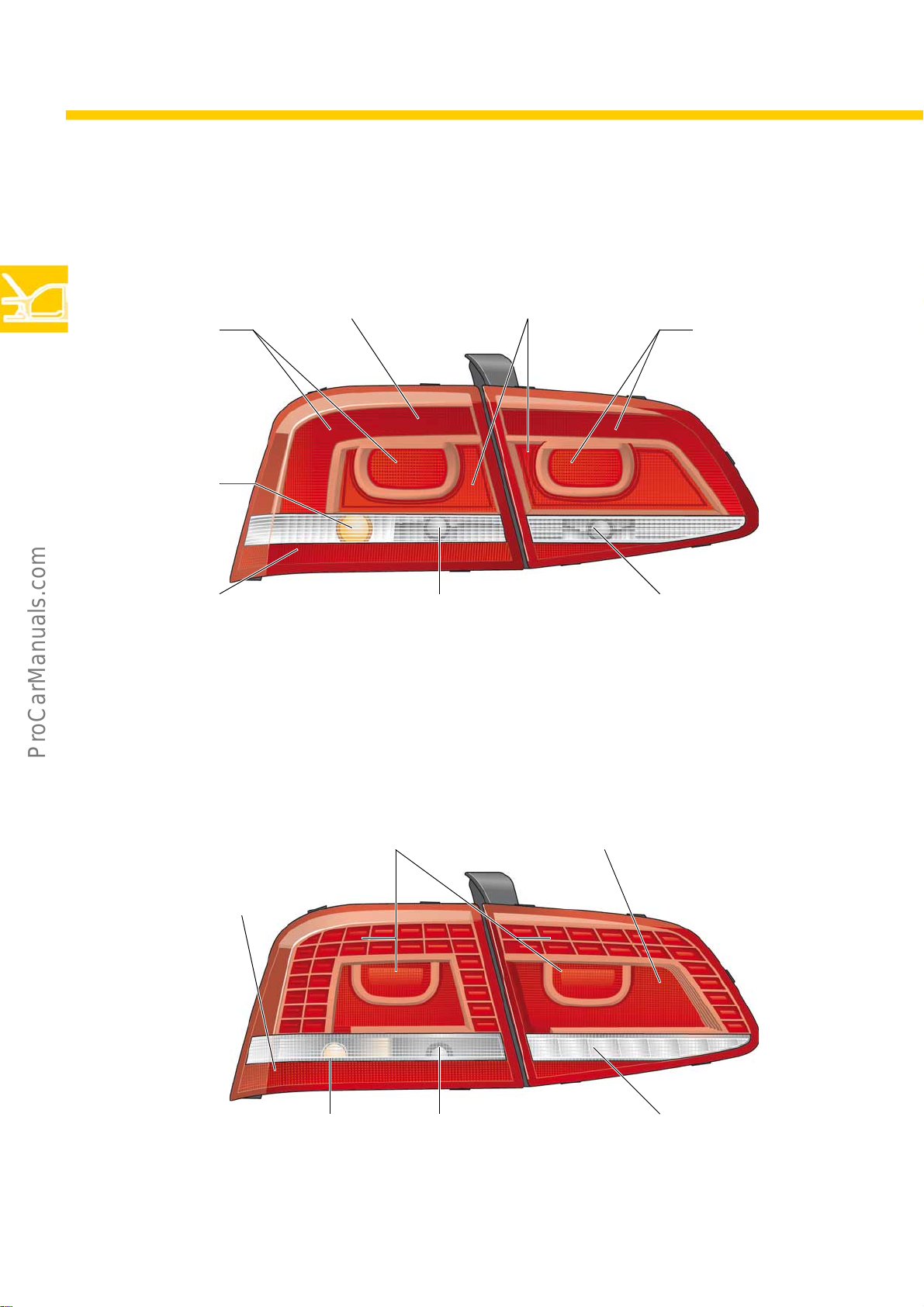
The tail lights of the Passat 2011 have a two part design. Only the outer lights are secured by a central bolt.
Tail light Reflector (in trim)
Brake light
Turn s i g nal
(21W)
Tail light
Reflector (in lens) Reversing light
LED tail lights
Access to the securing screws is on the left and right above the covers in the luggage compartment side panels.
Reflector
(in lens)
(16 W)
Tail and brake light
S488_050
Rear fog light
(LED 2.2W)
Reflector (in lens)
16
Turn signal (21W)
Reversing light
(16 W)
S488_048
Rear fog light
(3xLED; 3W total)
Page 17
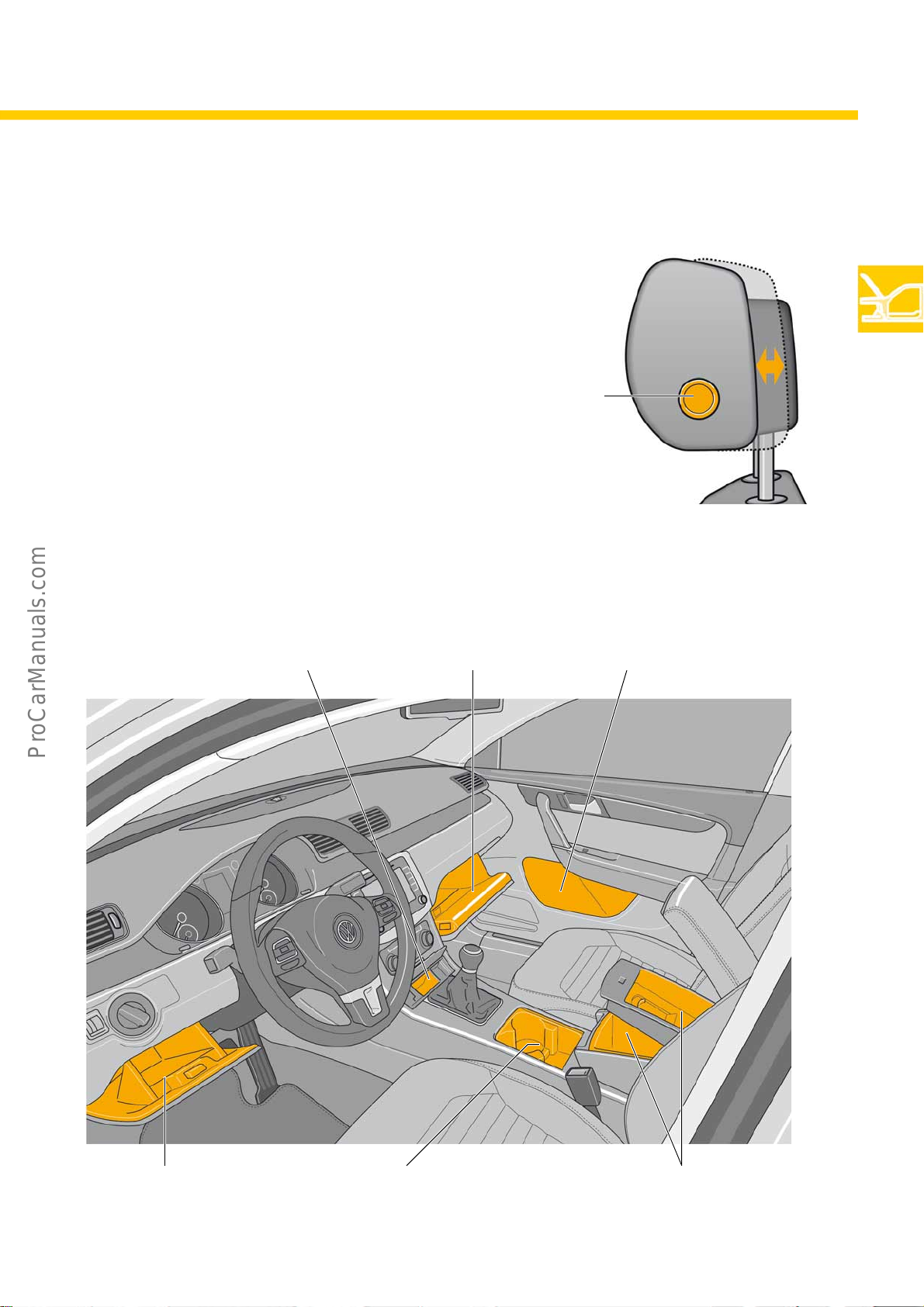
Interior equipment
Head restraints with Xadjustment
Once the release mechanism has been activated, the
head restraints in the Passat can be adjusted at the
base to be further away from or closer to the neck.
This helps to achieve an optimal position of the head
restraint, which, in addition to comfort, also enhances
safety.
Stowage facilities
Front
There are many multifunctional stowage compartments in he Passat. A centre armrest, which opens to reveal a
compartment, is an option in both the saloon and the estate.
Release
S488_052
Glove compartmentStorage under AC controls
Door compartment
S488_068
Small glove compartment by
steering wheel
Storage in centre console
with drink/can holder
Storage in centre armrest with cellphone
charging cradle and compartment beneath
17
Page 18
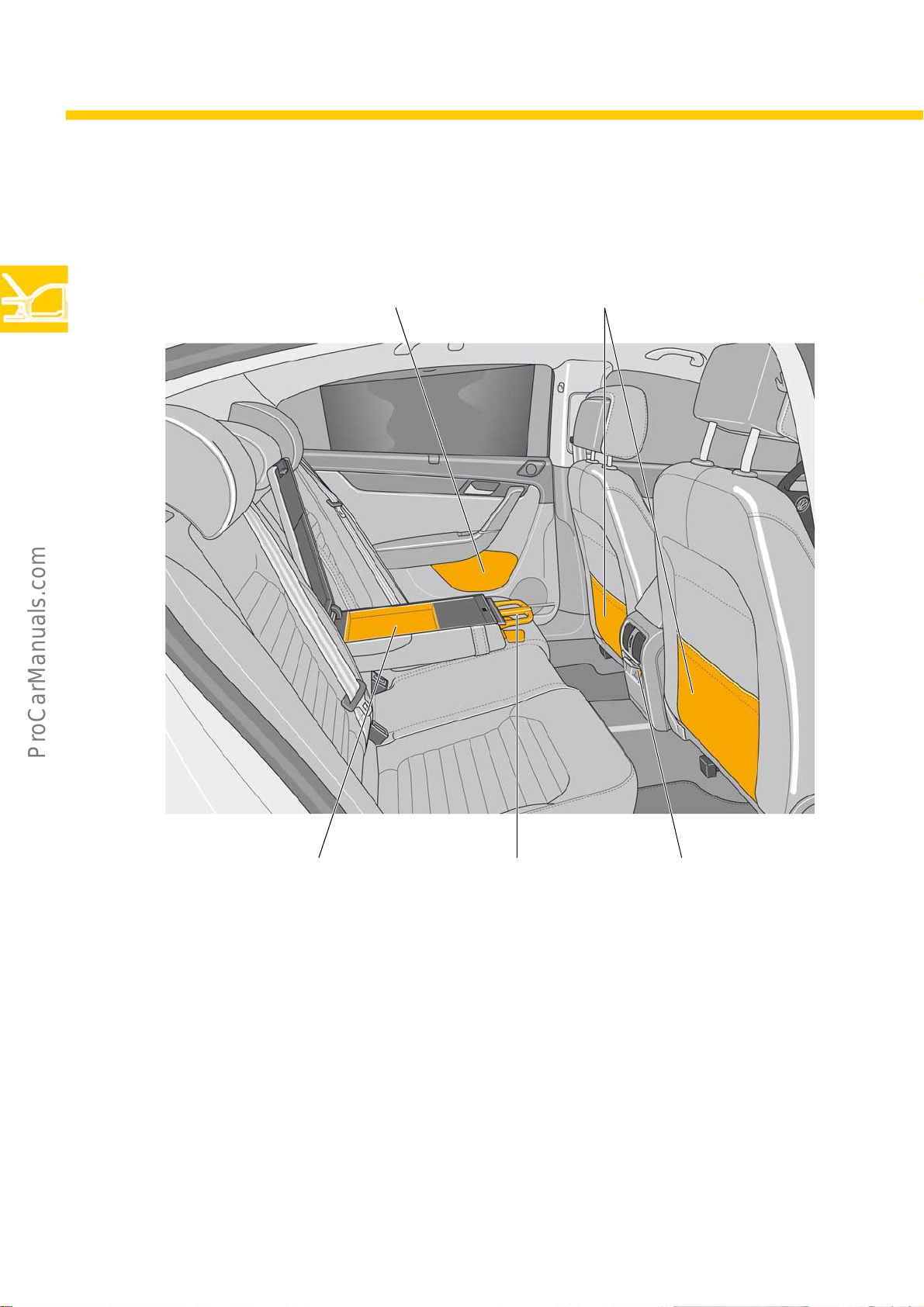
Body
In rear
Stowage pockets on
back of front seatsRear door compartment
in centre armrest
S488_066
Drink/can holderStorage compartment
12 volt connection
18
Page 19
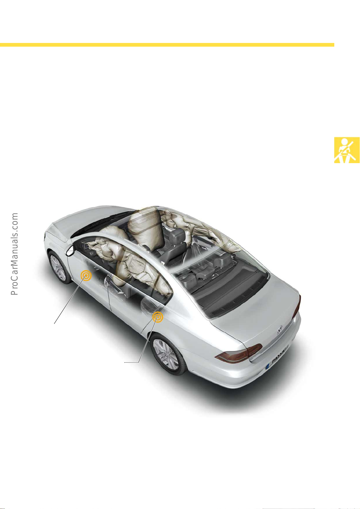
Occupant protection
Safety equipment
The new Passat is equipped as standard with six airbags: Driver and front passenger airbag, side airbags at front
and curtain airbags for front and rear passengers. As an option, two side airbags are available for the rear seats.
The crash sensors ensure that all airbags trigger safely.
Curtain airbag
The curtain airbag of the Passat 2011 ensures the
safety of occupants in all seat rows in the head and
shoulder area.
Side crash sensor
Front doors
Side crash sensor
C-pillar
Side crash sensors
The side crash sensors in the bottom area of the front
doors are designed as pressure sensors. Lateral
acceleration sensors to detect side impact are located
in the C-pillar.
S488_015
19
Page 20
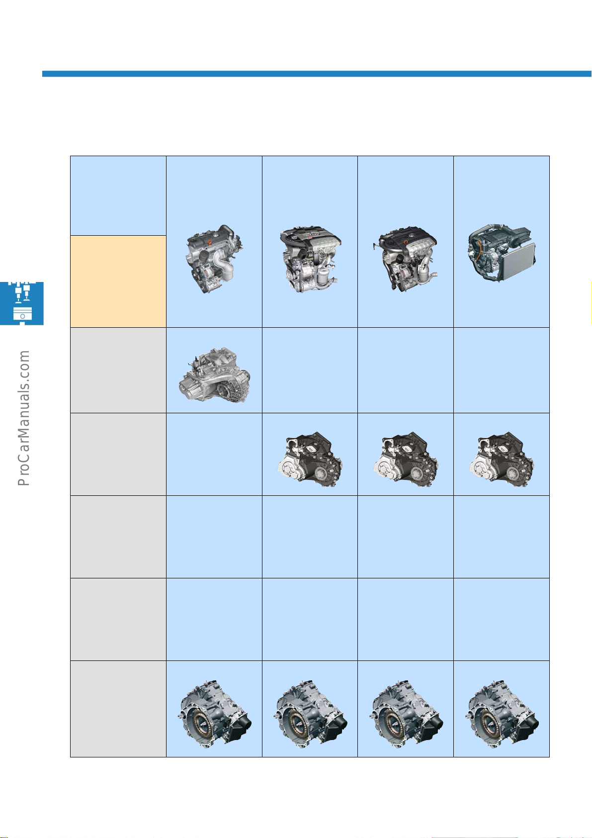
Engines
Engine/gearbox combinations
Petrol engine
Diesel engine
6-speed
manual gearbox
MQ200-6F
0AJ
6-speed
manual gearbox
MQ250-6F
02S
1.4l 90kW
TSI engine
with turbocharger
R+S R R R
1.4l 110kW
TSI engine
with dual charging
1.4l 118kW
TSI engine
with dual charging
1.8l 118kW
TSI engine
with 4-valve
technology
6-speed
manual gearbox
MQ350-6F
02Q
6-speed
dual clutch gearbox
DQ250-6F
02E
7-speed
dual clutch gearbox
DQ200-7F
0AM
R = with regenerative braking; S = with start-stop system (optional equipment)
20
Page 21
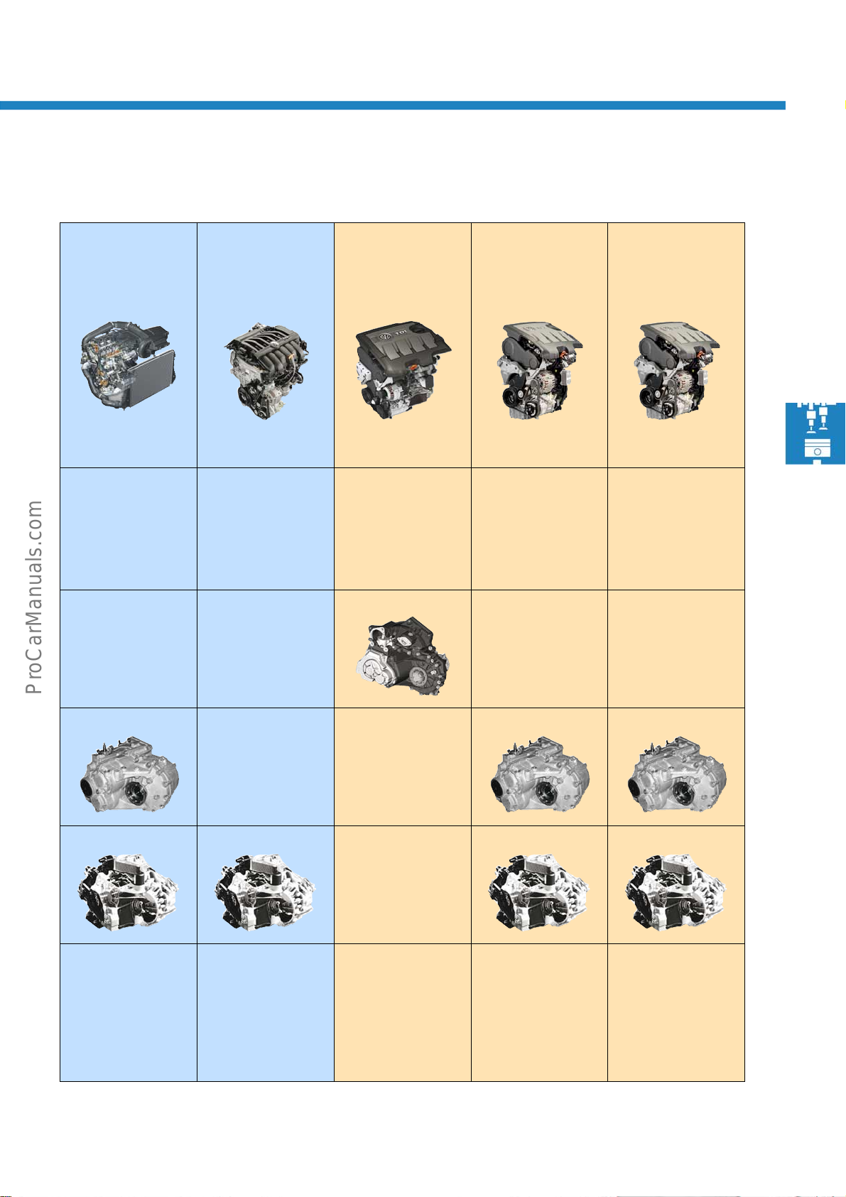
2.0l 155kW
TSI engine
with 4-valve
technology and
turbocharger
R R R+S R+S R+S
3.6l 220kW
FSI engine
with 4-valve
technology
1.6l 77kW
TDI CR engine
2.0l 103kW
TDI CR engine
2.0l 125kW
TDI CR engine
DQ250-6A DQ250-6F/A
F = front-wheel drive; A = four-wheel drive
MQ350-6F/A
21
Page 22
Engines
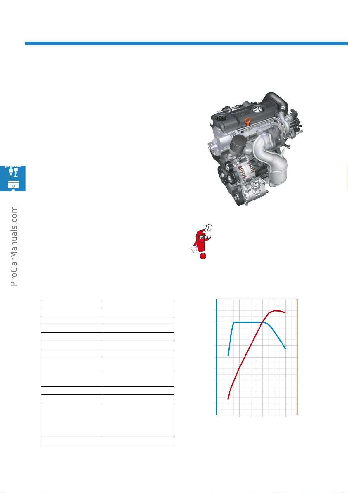
1.4l 90kW TSI engine with turbocharger
This engine has found application in other vehicle
models and was carried over.
Technical features
● Homogeneous mode (lambda 1)
● Turbocharger with wastegate
● Dual circuit cooling system
● Air-to-liquid charge air cooling
● Regulated duo-centric oil pump
● Demand-based fuel system
● High pressure fuel pump with integrated pressure
limiting valve
S488_201
Technical data Torque and power diagram
Engine code CAXA
Type 4-cylinder in-line engine
Displacement 1390 cm
Bore 76.5mm
Stroke 75.6mm
Valves per cylinder 4
Compression ratio 10:1
Maximum output 90kW at
Maximum torque 200Nm at
Engine management Bosch Motronic MED 17.5.5
Fuel Super unleaded RON 95
Exhaust gas treatment 3-way catalytic converter,
Emissions standard EU5
3
5000 rpm
1500 to 4000 rpm
broadband lambda probe
upstream and regular
lambda probe downstream of
catalytic converter
Further information on this engine can be
found in self-study programme
no. 405 "The 1.4l 90kW TSI engine with
turbocharger".
250
225
200
175
150
125
100
Tor q u e [ Nm ]
75
50
25
0
1000 3000 5000
Engine speed [rpm]
100
90
80
70
60
50
40
30
20
10
0
7000
S488_200
Output [kW]
22
Page 23
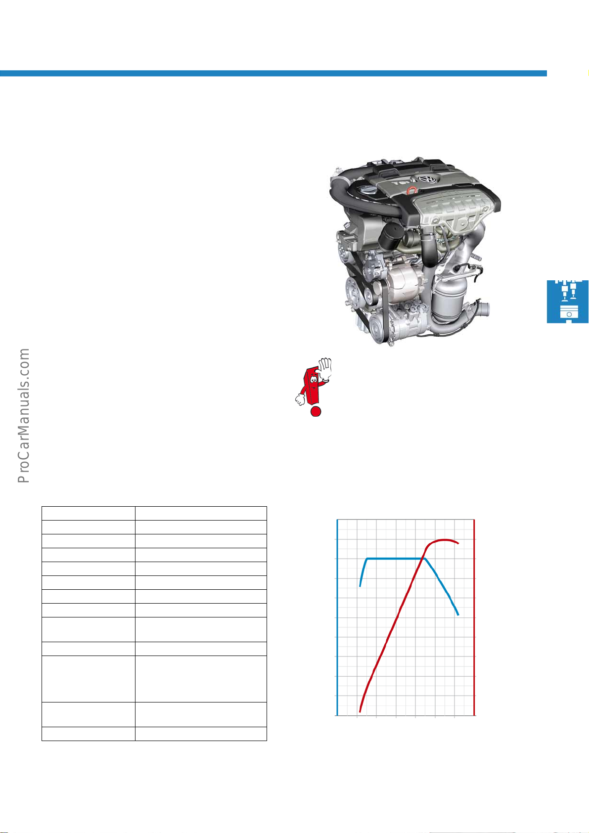
1.4l 110kW TSI engine with dual charging (EcoFuel)
This engine is practically the same as the EcoFuel
engine of the Passat 2010. Items changed are the
electronic gas pressure regulator and gas inlet valves.
Their function has remained the same, however.
Technical features
● One engine control unit for natural gas and petrol
operation
● Homogeneous mode (Lambda 1) in both operating
modes
● Turbocharger with wastegate
● Mechanical supercharger that can be activated
separately
● Mechanical pressure reduction stage discontinued
on electronic gas pressure regulator
● Optimised gas inlet valves, thereby making engine
start possible from -10 °C in natural gas mode
Further information on this engine can be
found in self-study programme no. 359
"The 1.4l TSI engine with dual charging" and
no. 425 "EcoFuel natural gas power with 1.4l
110kW TSI engine".
S488_231
Technical data Torque and power diagram
Engine code CDGA
Type 4-cylinder in-line engine
Displacement 1390cm
Bore 76.5mm
Stroke 75.6 mm
Valves per cylinder 4
Compression ratio 10:1
Maximum output 110kW at 5500 rpm
Maximum torque 220 Nm at
Engine management Bosch Motronic MED 17.1
Fuel Natural gas H (high)
Exhaust gas
treatment
Emissions standard EU5
3
1500 rpm to 4500 rpm
Natural gas L (low) with
reduced range
Super unleaded RON 95
Main catalytic converter,
lambda control
260
240
220
200
180
160
140
Tor q ue [ N m ]
120
100
80
60
1000 3000 5000
Engine speed [rpm]
7000
120
110
100
90
80
70
60
Output [kW]
50
40
30
20
S488_216
23
Page 24
Engines
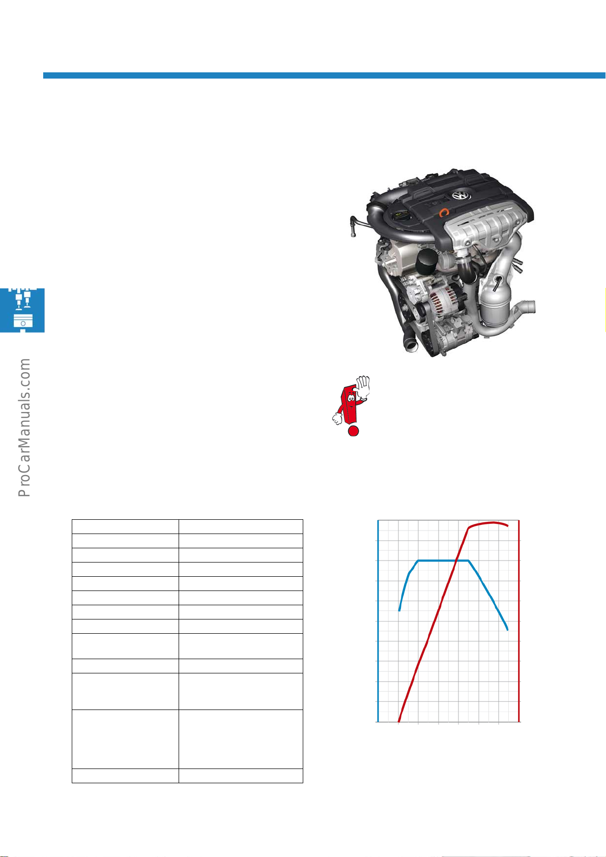
1.4l 118kW TSI engine with dual charging (MultiFuel)
This engine was first used as a bioethanol
version. First introduced in Sweden and Finland.
Technical features
● Bioethanol compatible up to 85%
● Fuel quality sender for detection of bioethanol
content in fuel
● Electric engine preheater in cooling system
● Cylinder head of 1.4l 110 kW TSI EcoFuel engine
● Homogeneous mode (lambda 1)
● Turbocharger with wastegate
● Mechanical supercharger that can be activated
separately
● High pressure fuel pump with a specially coated
pump piston that reduces friction and wear
Further information on this engine
can be found in self-study programme
no. 359 "The 1.4l TSI engine with dual
charging".
S488_203
Technical data Torque and power diagram
Engine code CKMA
Type 4-cylinder in-line engine
Displacement 1390 cm³
Bore 76.5mm
Stroke 75.6mm
Valves per cylinder 4
Compression ratio 10:1
Maximum output 118kW at 5800 rpm
Maximum torque 240Nm at
Engine management Bosch Motronic MED 17.1
Fuel Super unleaded RON 95
Exhaust gas treatment 3-way catalytic converter,
Emissions standard EU5
2000 to 4500 rpm
Ethanol can be mixed up to
85% (E85) in all conditions
broadband lambda probe
upstream and regular
lambda probe downstream of
catalytic converter
280
260
240
220
200
180
160
Tor q ue [ N m ]
140
120
100
80
1000 3000 5000
Engine speed [rpm]
120
110
100
90
80
70
60
50
40
30
20
7000
S488_202
Output [kW]
24
Page 25
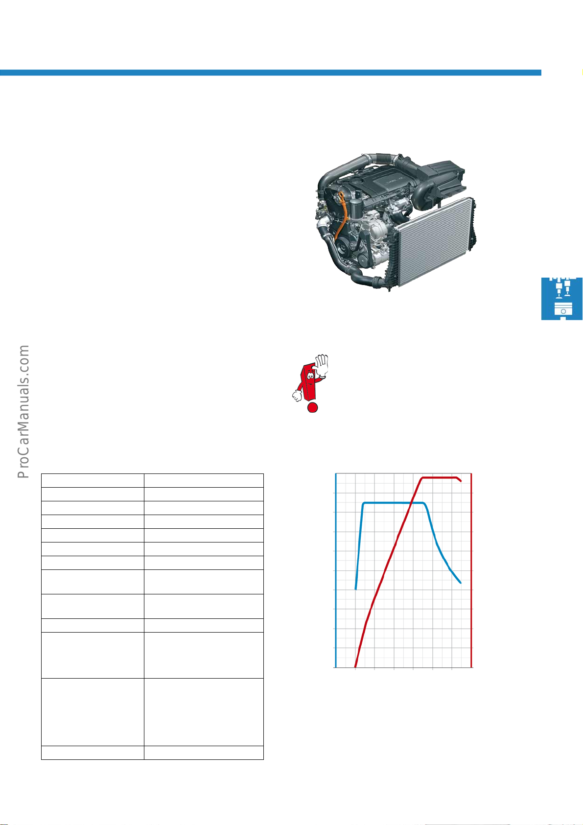
1.8l 118kW TSI engine with 4-valve technology
The 1.8l TSI engine designated EA888 is a technically
optimised further development of the familiar 4cylinder EA113 engine series. Tried and tested engine
components have been consistently further
developed. The engine also finds application in the
Golf GTI.
Technical features
● Improved pedestrian impact protection
● Significant improvement in comfort and acoustics
● Balancer shaft system with two shafts, offset in
height and each with three bearings
● Reduced repair complexity thanks to modified
housing of oil filter module
● Base engine configured for a very broad
performance range
● The turbocharger pressure unit can be exchanged
and adjusted.
Further information on this engine can be
found in self-study programme no. 401
"The 1.8l 118 kW TFSI engine with timing
chain".
Technical data Torque and power diagram
Engine code CDAA
Type 4-cylinder in-line engine
Displacement 1799 cm
Bore 82.5mm
Stroke 84.1mm
Valves per cylinder 4
Compression ratio 9.8:1
Maximum output 118kW at
Maximum torque 250Nm at
Engine management Bosch Motronic MED 17.5.2
Fuel Super unleaded RON 95
Exhaust gas treatment Upstream catalytic converter
Emissions standard EU5
3
4500 to 6200 rpm
1500 to 4500 rpm
(Normal unleaded RON 91
with marginally reduced
performance)
in proximity of engine with
upstream broadband probe,
main catalytic converter with
downstream regular lambda
probe
280
260
240
220
200
180
160
Tor q u e [ Nm ]
140
120
100
80
1000 3000
Engine speed [rpm]
5000
S488_227
120
110
100
90
80
70
60
50
40
30
20
7000
S488_226
Output [kW]
25
Page 26
Engines
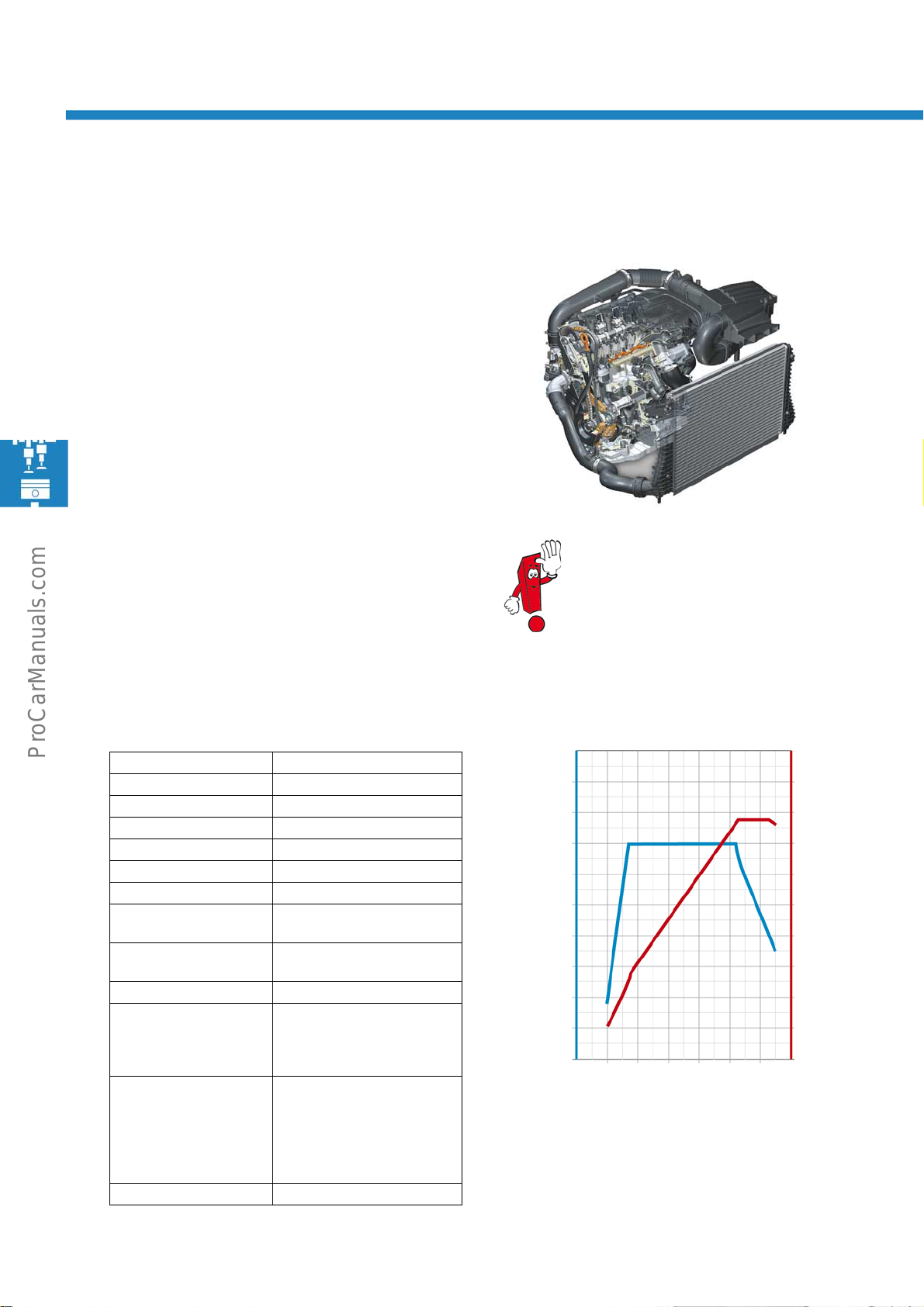
2.0l 155kW TSI engine with 4-valve technology and
turbocharger
The 2.0l TSI engine also belongs to the in-line 4cylinder EA888 engine series. It has the same design
as the 1.8l TSI engine, but with an increased capacity.
Technical features
● The higher displacement is achieved by modified
pistons, conrods and crankshaft.
● The turbocharger pressure unit CANNOT be
exchanged and adjusted.
S488_229
Technical data
Engine code CCZB
Type 4-cylinder in-line engine
Displacement 1984 cm
Bore 82.5mm
Stroke 92.8mm
Valves per cylinder 4
Compression ratio 9.6:1
Maximum output 155kW at
Maximum torque 280Nm at
Engine management Bosch Motronic MED 17.5.2
Fuel Super unleaded RON 95
Exhaust gas treatment Upstream catalytic converter
Emissions standard EU5
3
5300 to 6200 rpm
1700 to 5200 rpm
(Normal unleaded RON 91
with marginally reduced
performance)
in proximity of engine with
upstream broadband probe,
main catalytic converter with
downstream regular lambda
probe
Further information on this engine can be
found in self-study programme
no. 401 "The 1.8l 118 kW TFSI engine with
timing chain".
Torque and power diagram
340
320
300
280
260
240
220
Tor q ue [ N m ]
200
180
160
140
1000 3000 5000
Engine speed [rpm]
200
180
160
140
120
100
80
60
40
20
0
7000
S488_228
Output [kW]
26
Page 27
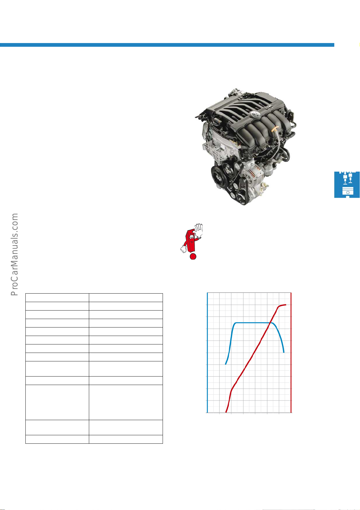
3.6l 220kW FSI engine with 4-valve technology
The 3.6l 220kW FSI engine with 4-valve technology is
a constituent of the VR engine series. Numerous
consumption-optimising measures have been
performed on the engine.
Technical features
● Oil pump output reduced and oil pressure lowered
to 3.6 bar
● Non-engaged chain tensioner
● 89° opening temperature of coolant
thermostat
● One-part oil pump chain sprocket
● Exhaust camshaft adjuster with 32°
setting range
● Vibration damper secured with 7 bolts
Further information on this engine can be
found in self-study programme
no. 360 "The 3.2l and 3.6l FSI engine"
S488_233
Engine code BWS
Type 6-cylinder in-line engine
Displacement 3597 cm
Bore 89mm
Stroke 96.4mm
Valves per cylinder 4
Compression ratio 11.4:1
Maximum output 220kW at 6600 rpm
Maximum torque 350Nm at
Engine management Bosch Motronic MED 17.1
Fuel Highest grade unleaded
Exhaust gas treatment Three-way catalytic converter
Emissions standard EU5
3
2400 to 5300 rpm
with RON 98
(Super unleaded RON 95 with
marginally reduced
performance)
with lambda control
Torque and power diagramTechnical data
400
380
360
340
320
300
280
Tor q ue [ N m ]
260
240
220
200
1000 3000
Engine speed [rpm]
5000
240
220
200
180
160
140
120
100
80
60
40
7000
S488_230
Output [kW]
27
Page 28
Engines
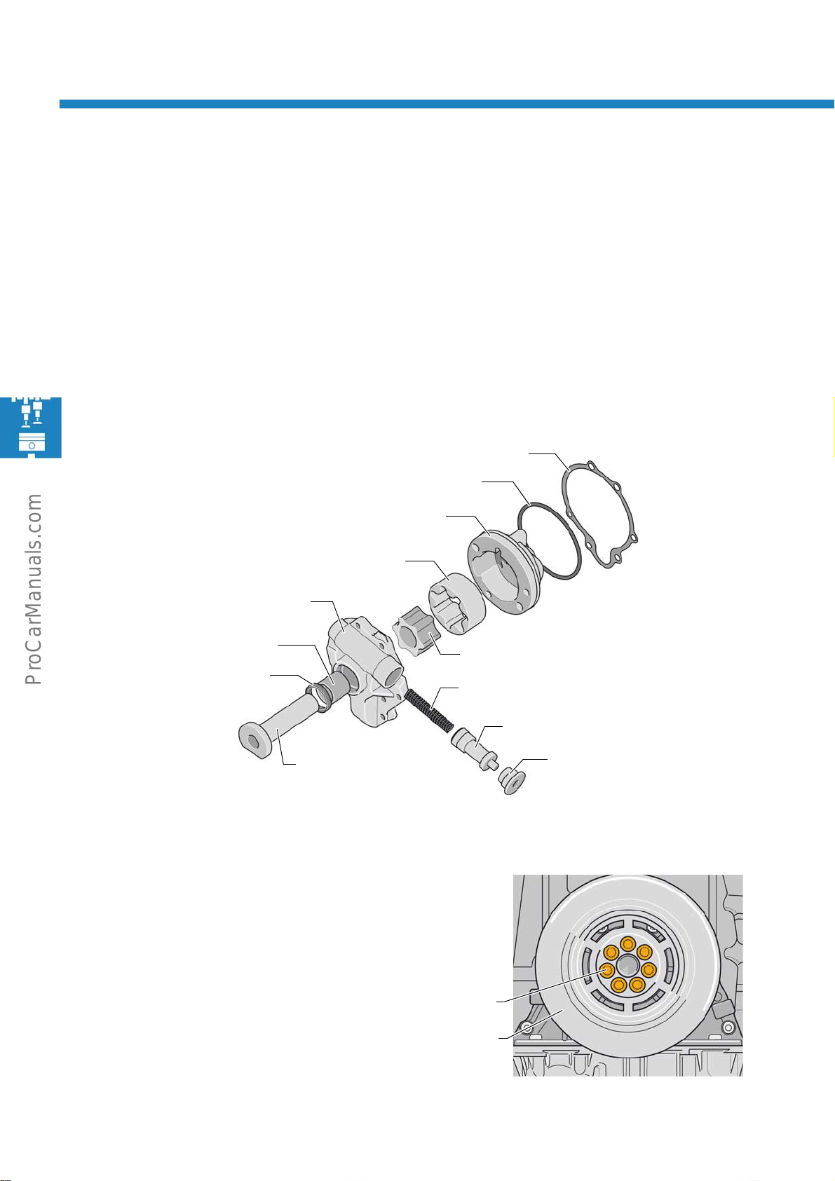
New features of 3.6l 220kW FSI engine
To reduce fuel consumption and the emission of CO2, several consumption optimising features were performed on
the engine. In addition, further innovative developments were implemented in the design of the engine.
Duo-centric oil pump
The entire oil circuit of the engine was improved and the output of the oil pump consequently reduced. In doing so,
it was possible to lower the opening oil pressure from 5.7bar to 3.6bar.
Gasket
Seal
1st half of housing
Bearing bush
Radial shaft seal
Vibration damper
To ensure secure attachment, the vibration damper is
secured with 7 bolts, as on the Passat R36
(previously one centre bolt).
2nd half of housing
Outer rotor
Drive shaft
S488_026
Inner rotor
Spring
Control plunger
Plug
28
Bolt attachment
Vibration damper
S488_234
Page 29
Chain tensioner
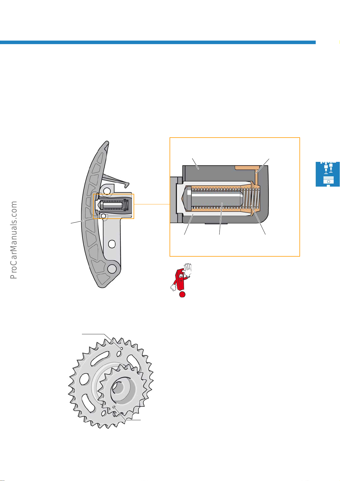
The lower chain tensioner has been optimised in terms of leaks and works without engagement at a lower oil flow
rate (originally 0.86l/min, now 0.04l/min). Without a locking mechanism it was possible to reduce the chain forces.
The spring serves to pretension the chain during cold starting. The ram serves purely to fill the void in the hollow
control plunger and thereby facilitates faster response from the chain tensioner when oil pressure is building up.
Chain tensioner module
Guide rail
S488_038
Housing
Control plunger
The choke bore must not be punched
through or cleaned using any kind of tool.
Ram
Choke bore
S488_036
Pretensioning
spring
Marking for primary
chain drive
S488_060
Chain sprocket
The oil pump chain sprocket has a one-piece design
to prevent incorrect fitment.
Marking for
camshaft timing
chain drive
29
Page 30
Engines
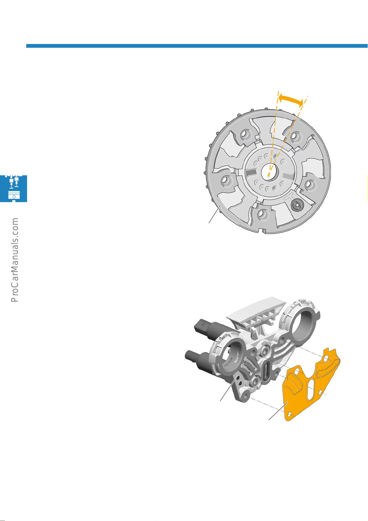
Camshaft adjuster
The exhaust camshaft adjuster only works in a 32°
range of crankshaft adjustment. At idle, less exhaust
gas flows back into the inlet port, which means
residual gas compression no longer occurs.
Engine running is thus smoother and consumption at
idling speed is reduced by about 3-5%
Range of adjustment
32°
Camshaft adjuster
S488_028
Camshaft adjuster cover
Located between the camshaft adjuster cover and the
cylinder head is a seal.
The seal optimises oil supply to the camshaft adjuster,
which in turn raises its adjustment speed.
Cover for
camshaft adjuster
S488_239
Seal
30
Page 31
1.6l 77kW TDI CR engine
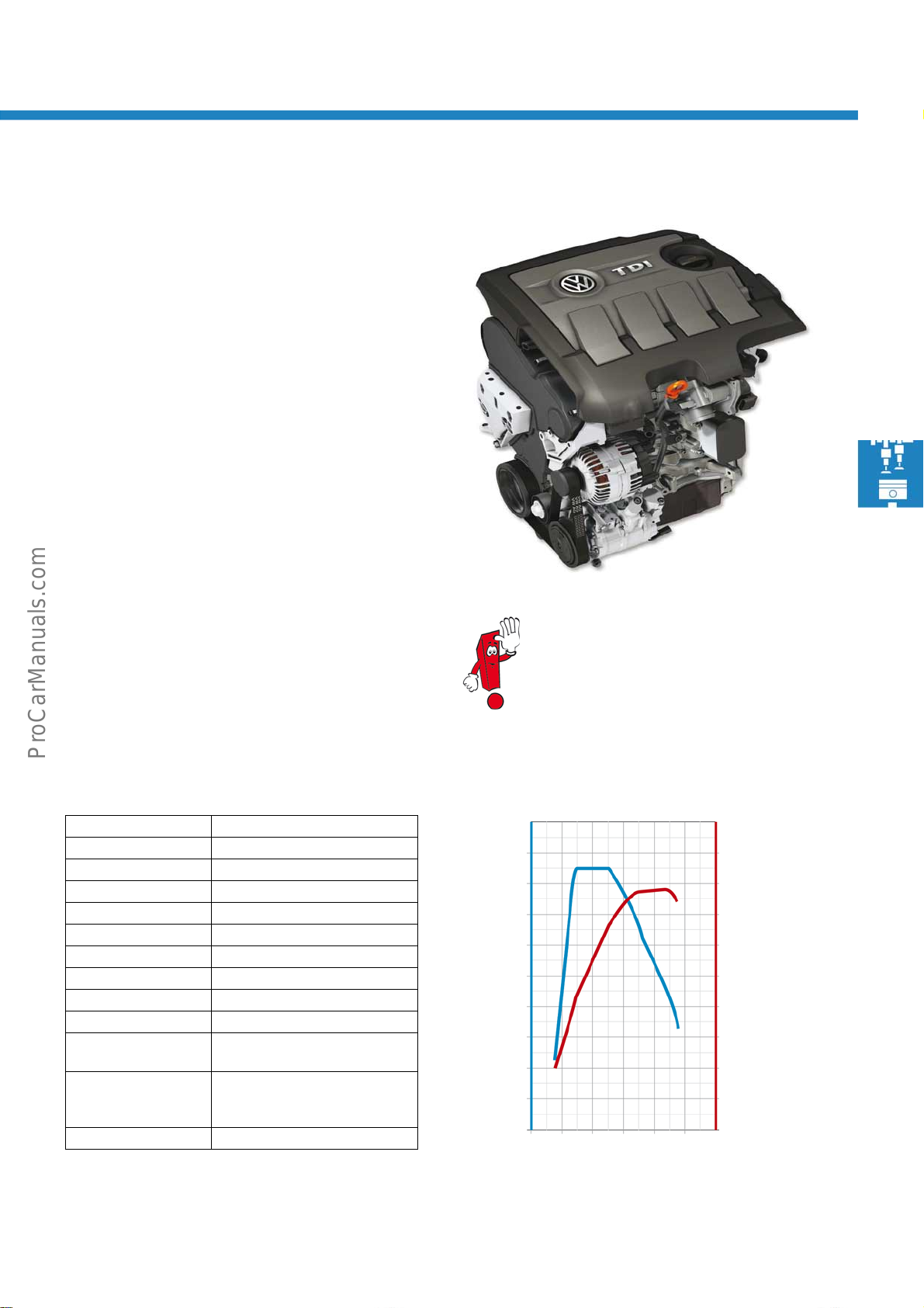
The 1.6l TDI CR engine, already tried and tested in the
Polo 2010, was further developed for use in the Passat
2011.
Technical features
● Common rail injection system with piezo injectors.
● EGR module with exhaust gas recirculation valve
and exhaust gas recirculation cooler.
● Plastic intake manifold without swirl plate
adjustment
● Spur gear drive for camshafts without
tooth backlash compensation
● Fuel high pressure pump without sprocket
for pressurisation pump
S488_205
The design and function of the
1.6l TDI CR engine is described in self-study
programme no. 442 "The 1.6l 77kW TDI
engine with common rail injection system".
Technical data
Engine code CAYC
Type 4-cylinder in-line engine
Displacement 1598cm
Bore 79.5mm
Stroke 80.5mm
Valves per cylinder 4
Compression ratio 16.5:1
Maximum output 77kW at 4400 rpm
Maximum torque 250Nm at 1500-2500 rpm
Engine management Simos PCR2.1
Fuel Diesel complying with DIN
Exhaust gas
treatment
Emissions standard EU5
3
EN590
Exhaust gas recirculation,
oxidising catalytic converter
and diesel particulate filter
Torque and power diagram
280
260
240
220
200
180
160
Tor q ue [ N m ]
140
120
100
0
1000 3000 5000
Engine speed [rpm]
100
90
80
70
60
50
40
30
20
10
10
S488_204
Output [kW]
31
Page 32
Engines
2.0l 103/125kW TDI CR engine
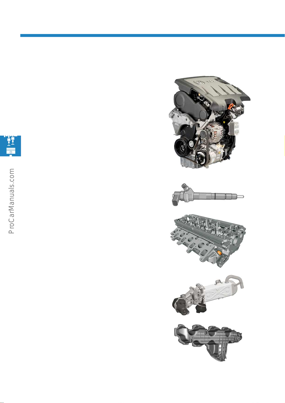
Second generation 2.0l TDI CR engines are used in
the Passat 2011. These engines are a further
development of the 2.0l TDI CR engine from the 1st
generation, tried and tested in many Volkswagen
models since 2007. The engine is offered with two
performance levels.
S488_207
Features of 2nd generation 2.0l TDI CR engine
Common rail fuel injection system with solenoid valve
controlled injectors
Cylinder head as on 1.6 l TDI CR engine with portion of
channel for recirculated gas running through cylinder
head
Exhaust gas recirculation module as on 1.6l TDI CR
engine with EGR valve and exhaust gas recirculation
cooler.
S488_206
S488_211
S488_209
32
Plastic intake manifold without swirl plate adjustment
S488_213
Page 33
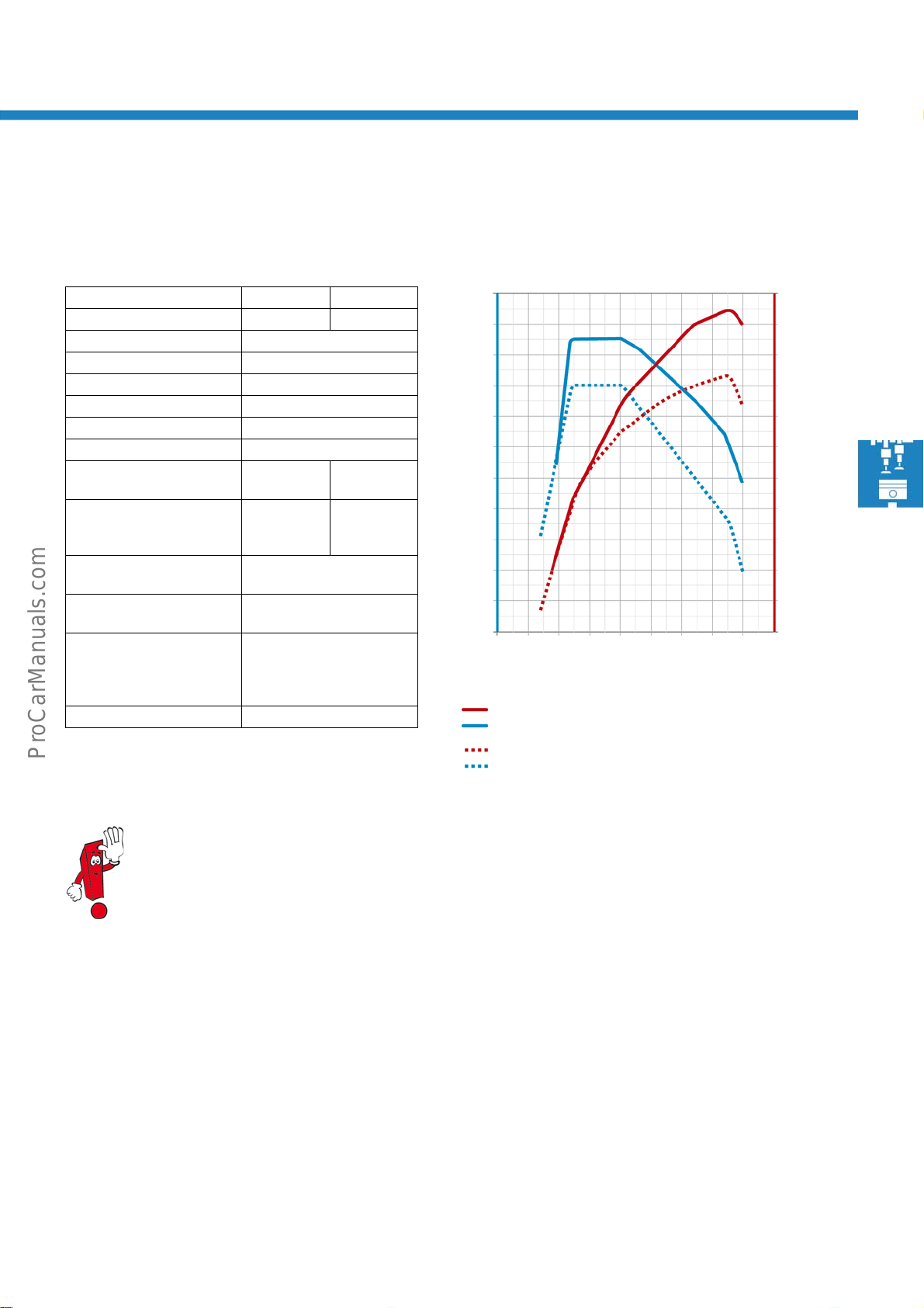
Technical data Torque and power diagram
Output 103kW 125kW
Engine code CFFB CFGB
Type 4-cylinder in-line engine
Displacement 19 68 cm
Bore 8 1mm
Stroke 95 .5mm
Valves per cylinder 4
Compression ratio 16.0:1
Maximum output 103kW at
4200 rpm
Maximum torque 320Nm at
1750 to
2500 rpm
Engine management Bosch EDC 17 (common rail
injection system)
Fuel Diesel complying with DIN
EN 590
Exhaust gas treatment Exhaust gas recirculation,
oxidising catalytic
converter,
diesel particulate filter
Emissions standard EU5
3
125kW at
4200 rpm
350Nm at
1750 to
2500 rpm
Nm
360
340
320
300
280
260
240
220
200
180
160
1000 2000 3000
Output [kW] - 125kW
Tor q u e [ N m ] - 1 2 5 kW
Output [kW] - 103kW
Tor q u e [ Nm] - 1 03 kW
kW
120
110
100
90
80
70
60
50
40
30
20
4000 5000
rpm
S488_208
● Detailed information about the 2.0l TDI CR engine can be found in self-study programme no. 403
"The 2.0l TDI engine with common rail injection system".
● The design and function of the 1.6l TDI CR engine is described in self-study programme no. 442
"The 1.6l TDI engine with common rail injection system".
● Further information about the solenoid valve controlled injectors can be found in
self-study programme no. 445 "The Sharan 2011".
● In combination with the 2.0l 103 kW TDI CR engine, the Passat 2011 can also be equipped with the
"Selective Catalytic Reduction" (SCR) exhaust gas treatment system as a Blue TDI version.
The SCR system serves as a means of reducing nitrogen oxide emissions and is described in detail in
self-study programme no. 424 "The exhaust gas treatment system: Selective catalytic reduction".
33
Page 34
Engines
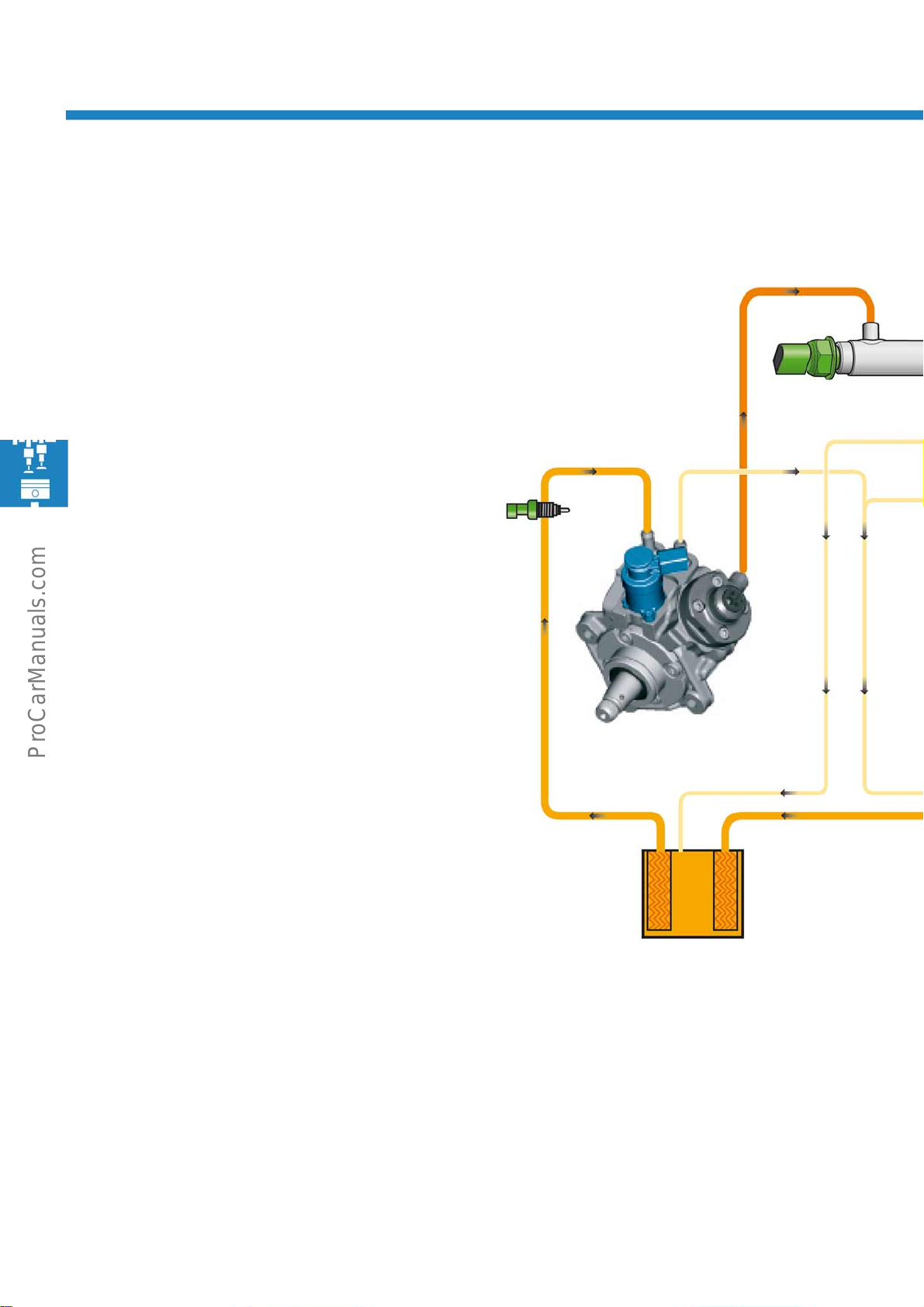
Fuel system for TDI engines
The overview shown represents the fuel system of the 2.0l TDI engine.
1 - Fuel system pressurisation pump G6
The fuel pump builds up pressure in the fuel supply
line.
2 - Fuel filter
The fuel filter keeps impurities in the diesel fuel away
from the components of the injection system. The high
precision components, for example, the high pressure
pump and the injectors, can be damaged or their
function impaired by even the most minute particles of
dirt.
8
3
5
3 - Fuel temperature sender G81
The fuel temperature sender measures the current fuel
temperature.
4 - High pressure pump
The high pressure pump generates the
fuel high pressure required for injection.
5 - Fuel metering valve N290
The fuel metering valve regulates the quantity of fuel
needed to generate the high pressure as required.
4
2
34
Page 35
6
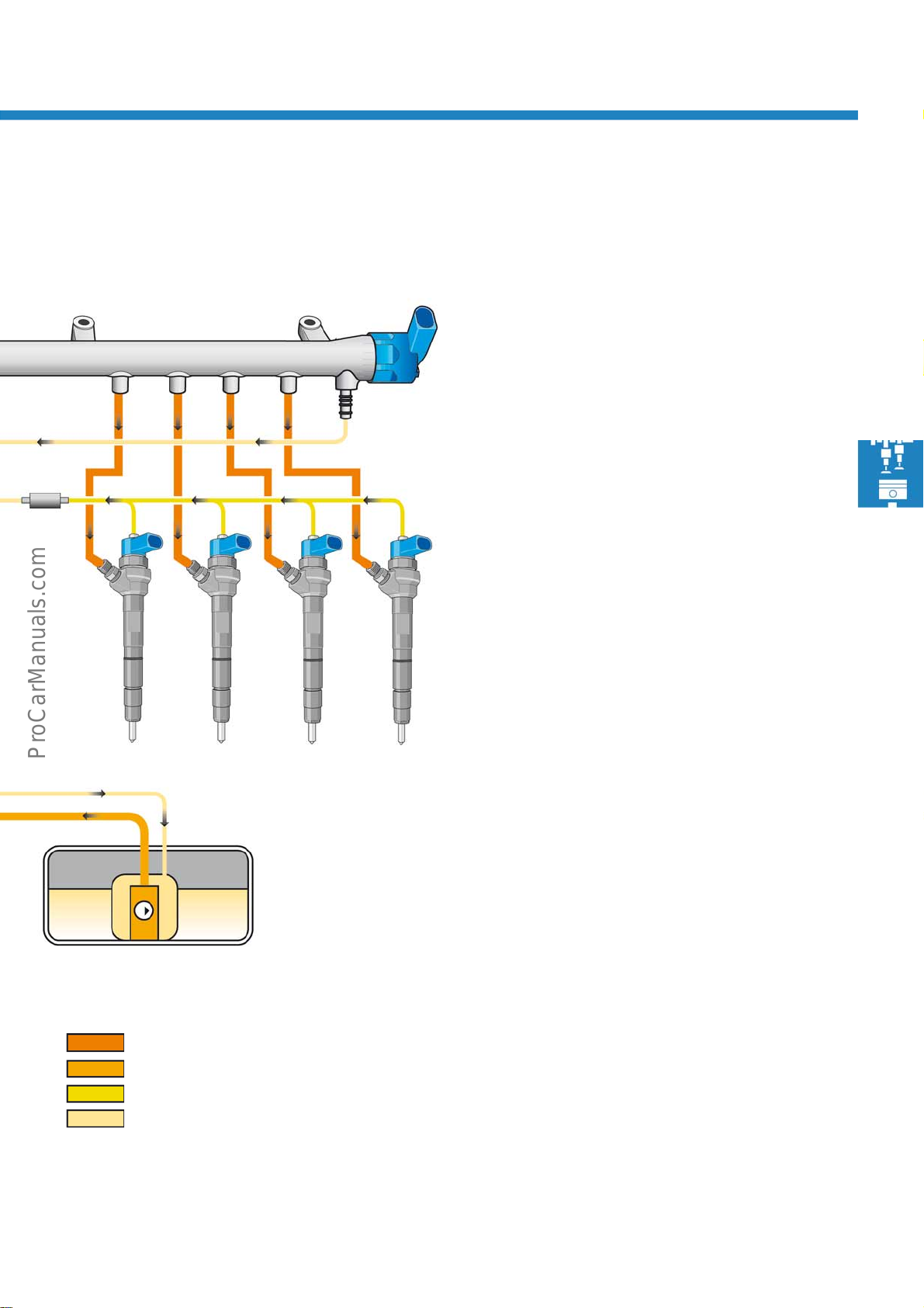
6 - Fuel pressure regulating valve N276
7
The fuel pressure regulating valve sets the
fuel pressure in the high pressure range.
7 - High pressure accumulator (rail)
The high pressure accumulator keeps the fuel
required for injection under high pressure for all
9
cylinders.
8 - Fuel pressure sender G247
10 10
1
Colour coding/key
High pressure
Supply pressure
Return pressure from injectors
10
10
The fuel pressure sender determines the current
fuel pressure in the high pressure range.
9 - Pressure retention valve
The pressure retention valve ensures that pressure
remains constant in the return flow to the injectors.
In this way fluctuations in pressure are avoided,
thereby making precise control of the injectors
possible.
10 - Injectors N30, N31, N32, N33
S488_220
The injectors inject fuel into the combustion chambers.
Return pressure
35
Page 36
Engines
Fuel system pressurisation pump G6
In the fuel system of the 1.6l TDI CR engine and the 2.0l TDI CR engines, the fuel system pressurisation pump
generates the fuel pressure required for the low pressure system in the fuel tank.
As a consequence, the gear-type pump used in the high pressure pump of the previous model in the fuel system of
the 1.6l TDI CR engine is no longer required. Likewise, the electric pressurisation pump in the supply line of the low
pressure fuel system of the 2.0 l TDI CR engine has been discontinued.
The fuel system pressurisation pump in the Passat 2011 is an electrically driven internal gear pump. It is located in
the fuel delivery unit GX1. In the fuel pressurisation system for diesel engines, the pump generates a pressure of
approx. 6bar. This ensures that the high pressure pump is supplied with sufficient fuel in all operating conditions.
A valve in the high pressure pump reduces the fuel pressure generated by the fuel system pressurisation pump in
the fuel supply line to approx. 5 bar. This maintains a constant level of pressure in the fuel supply line.
The fuel pump is activated by the engine control unit via a relay when the engine is started.
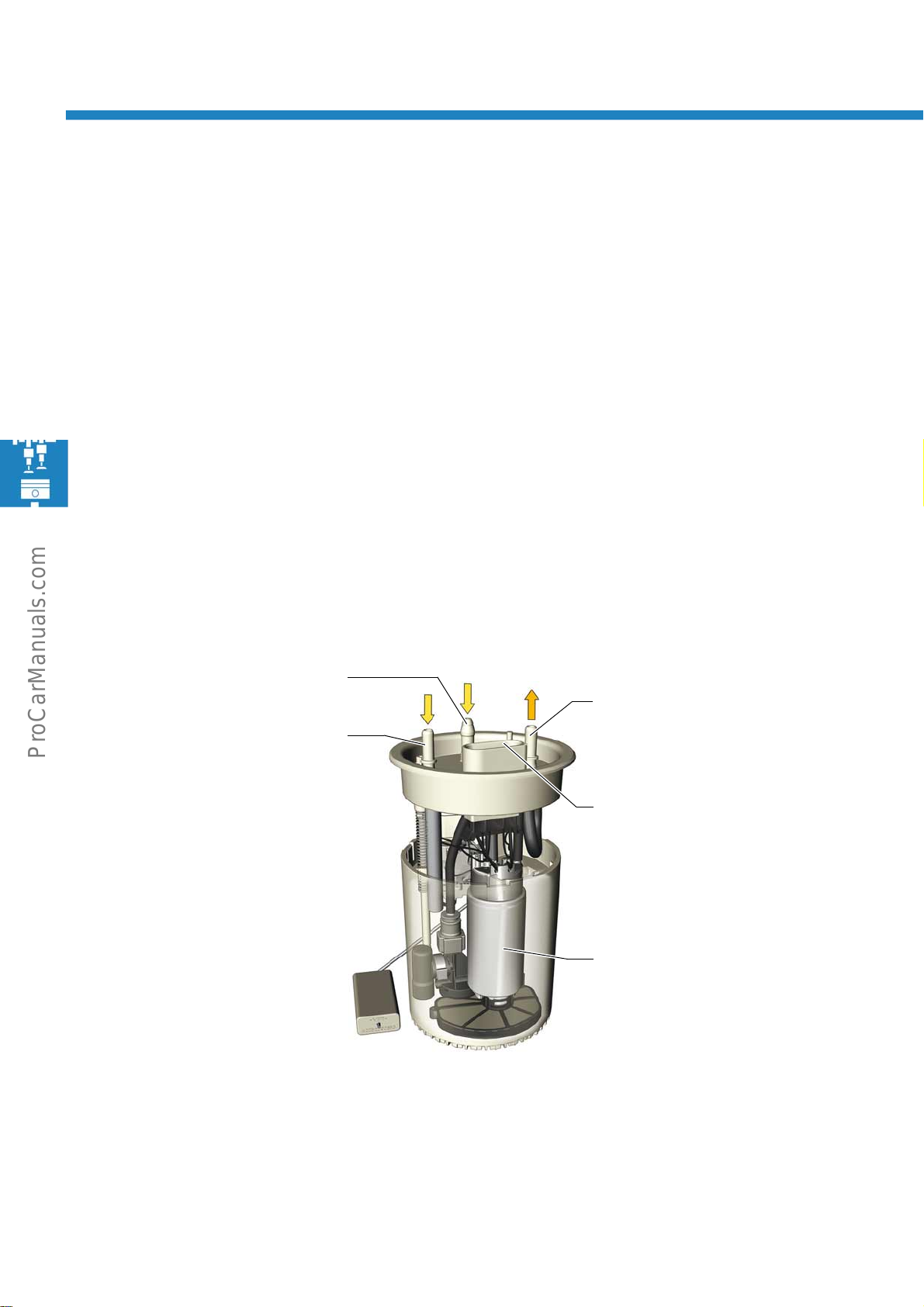
Design of fuel delivery unit GX1
Fuel line for
auxiliary heater
Fuel supply
Fuel return
Electrical connection
Fuel system
pressurisation pump G6
S488_215
36
Effects in event of failure
The engine will not run if the fuel system pressurisation pump fails.
Page 37
Power transmission
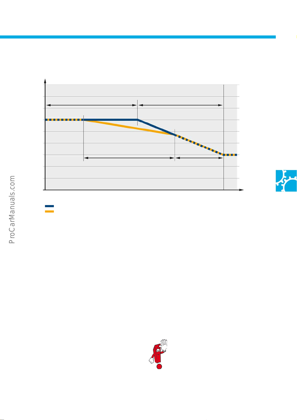
Dual clutch gearbox with freewheel function
Steady consumption
Speed [km/h]
Distance [m]
Dual clutch gearbox without freewheel function
Dual clutch gearbox with freewheel function
The 6-speed dual clutch gearbox 02E and the 7-speed dual clutch gearbox 0AM can be ordered for the the new
Passat with a freewheel function.
Overrun cut-off
Overrun cut-offCoasting
S488_240
The role of the freewheel function is to isolate the engine from the gearbox at overrun. This is made possible by
opening the dual clutch. The engine turns at idling speed and the vehicle coasts without any engine braking effect.
With the freewheel function and by driving with foresight, fuel can be saved.
The freewheel function is only possible with the selector lever in the "D" position. If the selector lever is in the "S"
position or in the tiptronic gate, or if the driver presses the brake, the freewheel function is suppressed.
Not until the engine is placed under load again is the freewheel function reactivated.
On dual clutch gearboxes with freewheel
function, the gear shift points with the
selector lever in "S" are only marginally
higher than those in the "D" position.
37
Page 38
Power transmission
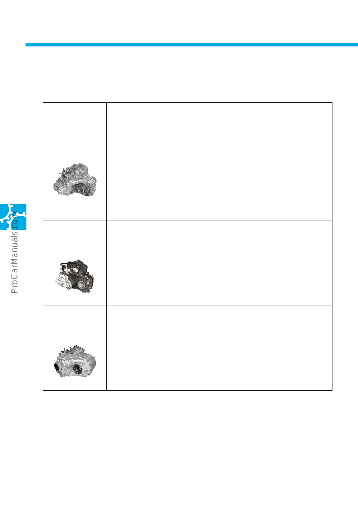
Overview of gearboxes
Manual gearbox
Gearbox type Technical features Further
information
6-speed
manual gearbox
MQ200-6F 0AJ
6-speed
manual gearbox
MQ250-6F 02S
● Further development of 0AG gearbox
● Adapted for 1.4l 90 kW TSI engine, gap between pinion shaft
and differential increased, sheet metal bearing support replaced
by cast metal bearing support for higher torque, teeth ground
● Final drive uprated
● Without speedometer sender
● CO
● Torque capacity up to 200Nm
● Further development from 0A4
● Longer shafts with additional bearings, additional gear pair,
-optimised gear ratios
2
new longer housing lid made from aluminium
● Without speedometer sender
● CO
● Torque capacity up to 250Nm
-optimised gear ratios
2
SSP 237
SSP 306
SSP 99
SSP 306
38
6-speed
manual gearbox
MQ350-6F 02Q
● Further development of 02M gearbox
● Changes to selector shaft, selector forks with stops in housing,
modified bearings
● Without speedometer sender
● Torque capacity up to 350Nm
SSP 205
SSP 306
Page 39
Dual clutch gearbox
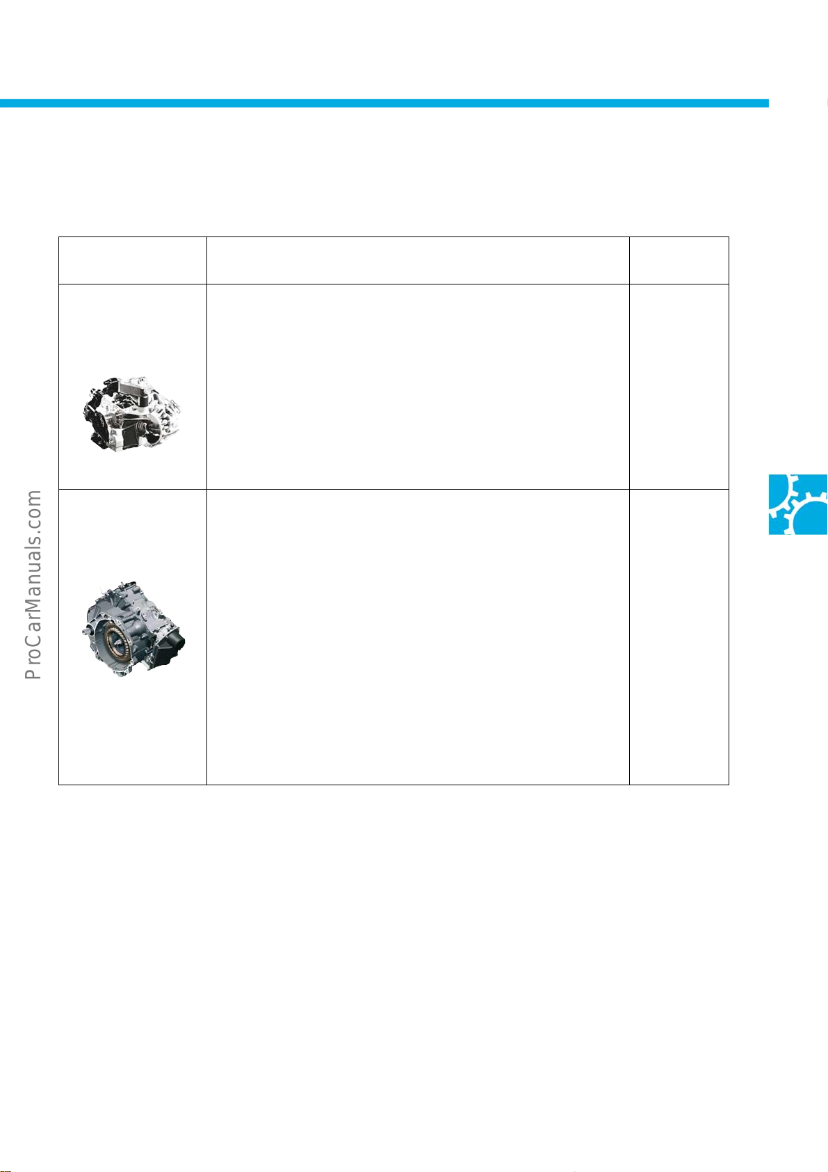
Gearbox type Technical features Further
information
6-speed
dual clutch gearbox
DQ250-6F DSG 02E
7-speed
dual clutch gearbox
DQ200-7F 0AM
The 6-speed dual clutch gearbox 02E is equipped with a hydraulic
dual clutch. It combines the high level of efficiency as well as
sturdiness and sportiness of a manual gearbox with the high level of
comfort of an automatic gearbox during gear changes.
The 7-speed dual clutch gearbox 0AM is a further development of the
6-speed dual clutch gearbox 02E.
Unlike the 02E, it works with a dry-plate dual clutch and separate oil
circuits for the gearbox and mechatronics.
Another difference to the 02E is that the electric oil pump for the
hydraulics is only actuated by the control unit when required.
Actuation occurs once hydraulic pressure in the mechatronics drops
below a certain value, necessitating an increase in pressure again in
order to assure operability of the mechatronics.
SSP 308
SSP 390
39
Page 40
Running gear
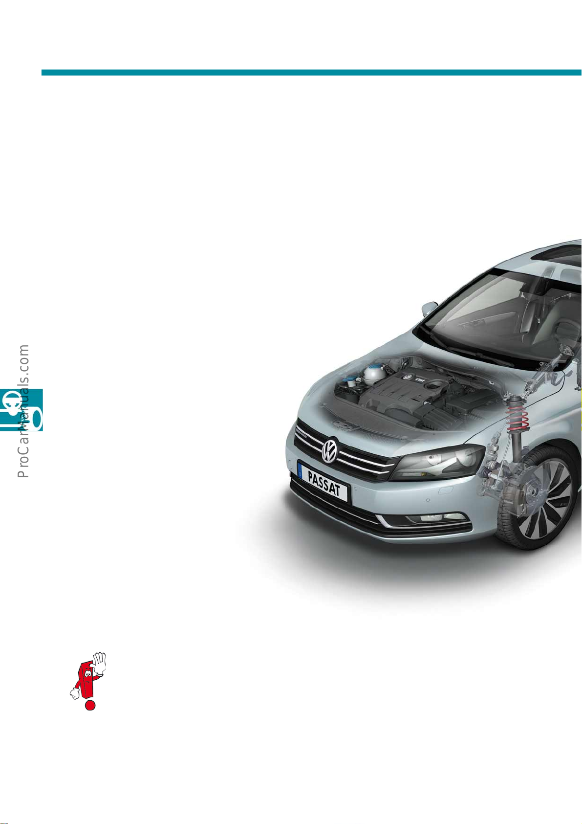
Overview
The Passat 2011 offers the highest level of driving comfort thanks to its running gear configuration. The running
gear is based in essence on the tried and tested running gear of the Passat 2006. Sporty and standard running
gear versions are available, as well as adaptive chassis control DCC.
● Extended EDL (XDS)
● Lightweight McPherson strut
front suspension
● Parallel axis power steering (APA)
● ESP/ABS TRW 450M
● Tyre pressure monitoring
TPM with auto location
● Further details about the power steering system can be found in self-study programme
no. 399 "The electromechanical steering with parallel axis drive".
● For further details about the adaptive chassis control, see self-study programme no. 406
"The adaptive chassis control DCC".
● Adaptive chassis control DCC,
optional
40
Page 41
● AUTO HOLD function
● Electromechanical parking brake
● Four-link rear suspension
S488_027
● Auto leveling on rear axle,
optional
● Fatigue Detection System (FDS)
● ContiSeal tyres from 17" rims
● Further details about the self-leveling system can be found in
self-study programme no. 357 "The Nivomat".
● Further details about the parking brake can be found in
self-study programme no. 346 "The electromechanical parking brake".
41
Page 42
Running gear
Extended EDL (XDS)
The Volkswagen Passat 2011 is equipped with the ESP extension XDS on vehicles with diesel engines from 125kW
and on vehicles with petrol engines from 220kW. XDS keeps the wheel on the inside of the corner within the slip
limit during fast cornering. Up to a defined torque level, XDS decelerates the wheel on the inside of the corner, thus
enabling any increase in torque at the vertex to be offset against the wheel on the outside of the corner. This
feature only works if the vehicle is accelerated in the corner and sufficient torque is available. The effect is greater
in tight bends in 2nd or 3rdgear and at higher road speeds than in bends with larger radii.
With XDS
● Better traction
● Greater agility
● Follows line of drive better due to less steering
angle requirement
● Reduced tendency to understeer
● Greater speed out of corners possible
XDS already finds application in the Golf 6
GTI/GTD and Polo 5 GTI.
Key:
Key:
with XDS
with XDS
without XDS
without XDS
S488_074
Without XDS
● Torque at wheels cannot be increased
● TCS/EDL/engine torque intervention
42
Page 43
Tyre pressure monitoring TPM with auto location
A new, direct measuring tyre pressure monitoring system is employed in the Passat. As before, the system uses
sensors in the tyre that report the inflation pressure to the control unit in the vehicle. With the "auto location"
feature, the system is capable of clearly identifying and displaying any tyre affected by pressure loss. Furthermore,
there is an option of displaying the inflation pressures of all tyres in the dash panel display.
The "intelligent aerial" is a combination of TPM auto location control unit and central reception aerial. It is
connected to the onboard supply via the extended CAN. Term.15, the speed signal and the reversing signal serve
as input parameters. The "intelligent aerial" can be found on the outside of the body in the rear (vicinity of spare
wheel well) in a place where reception is favourable.
S488_078
S488_080
Vehicle status
TPM auto location control unit
with central reception aerial
Key:
Reception with high level (rear)
Once the vehicle is in motion, the electronics in each
wheel start sending data telegrams. Some of the
information these data telegrams contain is as
follows:
● ID (identification)
● Pressure
● Temperature
● Direction of rotation
Dash panel insert with
controls
Example of display in
dash panel insert
Wheel electronics with detection
of rotational direction
Reception with low level (front)
With the direction of rotation data, it is possible even
after a short time of driving for each set of electronics
to be allocated to the individual wheels. In line with
this, the front and rear are identified by a level
assessment (which is why the reception aerial is
positioned on the rear bumper). This makes it possible
to clearly identify the location of every set of wheel
electronics.
43
Page 44
Driver assist systems
Fatigue Detection System (FDS)
Driver fatigue is detected by monitoring the steering behaviour. The system meets the following criteria:
● Driver alert when fatigue is detected
● Fatigue monitoring only on motorways, dual carriageways and wide A roads
● Does not become operable until above 65km/h
● No imminent warning in event of microsleep
Function and display
The system stores a reference map in the gateway control unit based on the steering behaviour during the first 15
minutes of driving. A comparison of the driver's current steering response with this reference map is carried out and
evaluated. An alert is issued no earlier than 15 minutes of continual driving.
Displays in dash panel insert (example of German versions)
"Lowline"
The function analyses the driver's behaviour while driving the vehicle and detects driver fatigue from certain
patterns. The function cannot detect fatigue among all drivers as not all drivers demonstrate the same typical
steering behaviour.
If the behaviour falls into the fatigue category, the driver is alerted for 5 seconds by a message in the dash panel
and a gong. If the driver fails to take a break within the next 15 minutes, the message and gong are repeated. No
further message is given once it has been repeated. When the ignition is switched off, the reference map is cleared.
S488_136
"Highline"
S488_138
S488_076
"Premium"
44
Page 45
Adaptive Cruise Control (ACC)
Adaptive Cruise Control (ACC) regulates the speed and the distance of the vehicle in relation to the traffic ahead at
a value predetermined by the driver. In all situations, the driver remains master of the situation in as far as the
system can be switched off or the intervention can be interrupted at any time by pressing the brake or accelerator
pedal.
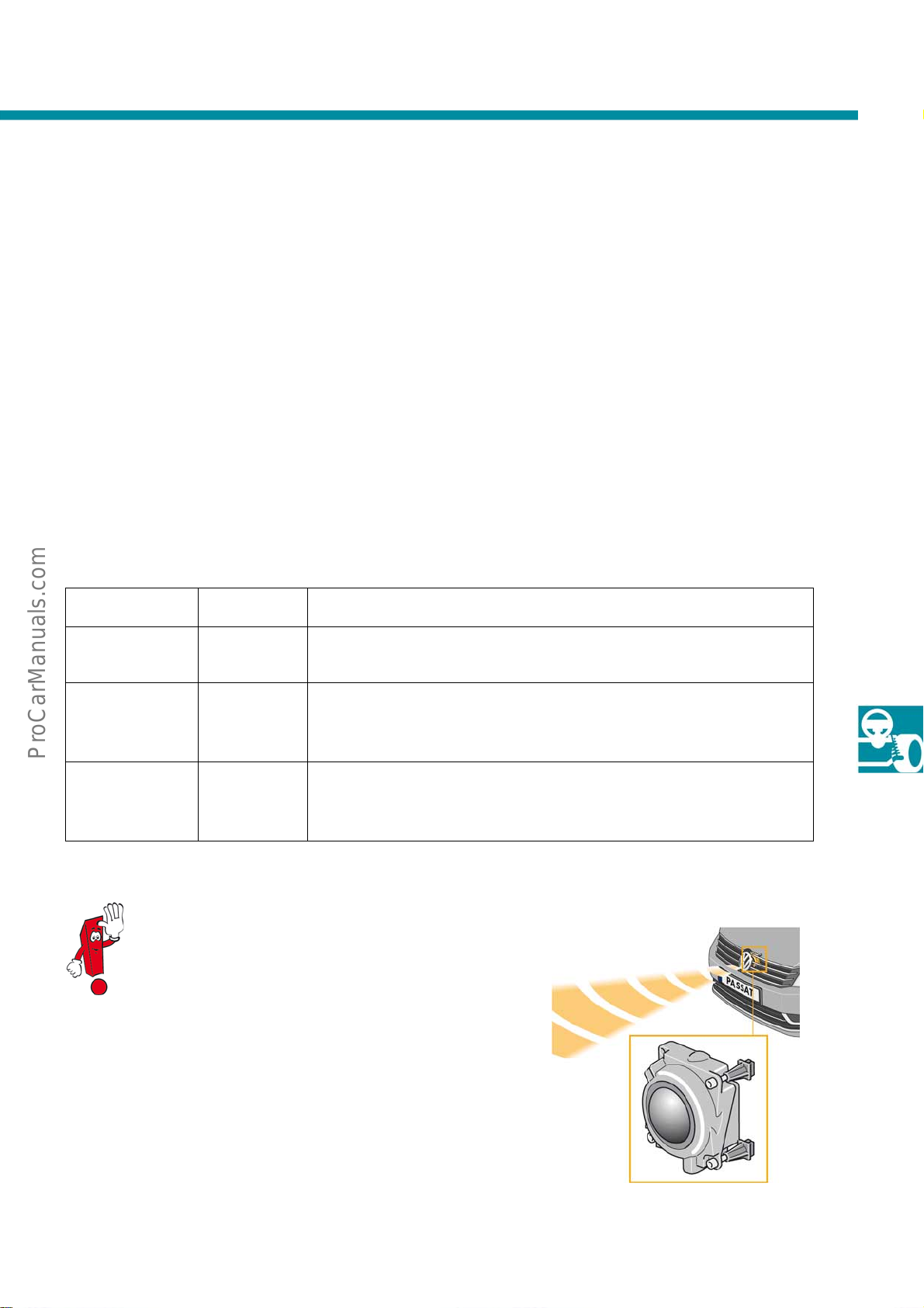
The Front Assist feature integrated in the ACC helps as an "alert co-driver" to avoid any collision with moving traffic
– remaining alert even when the ACC is switched off.
The new City Emergency Brake function also reacts to parked vehicles at speeds below 30 km/h. In the event of
danger, it initiates a brake manoeuvre and can thereby help to avoid an imminent collision or reduce the amount
of damage caused as a result.
Terminology for driver assist systems
Name
ACC
(Adaptive Cruise
Control)
Front Assist Front Scan
Formerly
known as
ADC Maintains specific distance in relation to vehicle travelling ahead and adapts speed
City Emergency
Brake
Brake interventions avoid accidents only in
exceptional circumstances.
N/A
Function
Short description of function
dynamically to traffic flow.
Conditions vehicle, alerts driver to hazardous situations and improves
driving dynamics during overtaking manoeuvres. Reacts to moving vehicles
only at speeds greater than 30km/h.
Co-function of front assist. Automatically brakes the vehicle prior to a
collision. Reacts to moving and stationary vehicles at speeds less than
30km/h.
If the road ahead is clear, ACC moderately accelerates the vehicle up
to the desired (set) speed. If a vehicle travelling ahead in the same
lane is moving more slowly, the system brakes so that the vehicle
ahead can be followed comfortably.
S488_090
45
Page 46
Driver assist systems
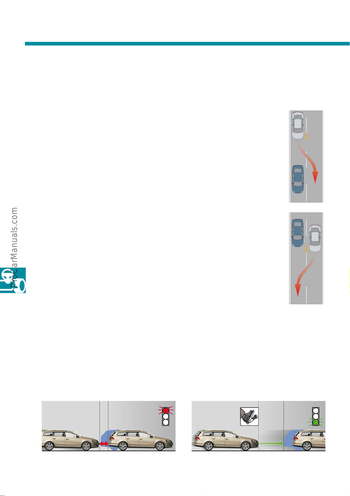
Optimised lane change function
When the turn signal is activated, the system detects an intention to overtake and improves the dynamics while
taking safe distances into account.
Veering out
If, with the ACC active, the Passat approaches a
vehicle travelling ahead, all that is required is for the
turn signal to be activated and the Passat will
accelerate up to the set speed when veering out. In
this way, the vehicle can be overtaken comfortably.
ACC helps to maintain the safe distance
automatically.
Veering in
If the driver activates the turn signal after the vehicle
has been overtaken, the road speed is reduced back
to the value set in the ACC.
Example (80km/h set)
1) Appr oaching a slower
vehicle. Speed adapted to
target.
2) Driver indicates and veers out:
system accelerates automatically
to 80 km/h.
S488_122
3) Driv er indicates.
4) Driver veers in: automatic follow-on
with ACC set to 80km/h.
Go Trigger
In combination with a DSG gearbox, the vehicle can
be brought to a halt when following traffic (follow to
stop). A safe distance is taken into account in this case.
Vehicle brought to halt
within safe distance
S488_124
As soon as the vehicle travelling ahead gains distance
and the driver briefly presses the accelerator, the ACC
takes up its control function again immediately (Go
Trigger).
Go Trigger
S488_126 S488_128
46
Page 47
Front Assist
General description
Front Assist aids as an "alert co-driver" in certain situations to avoid collisions with traffic - even with the ACC
switched off. The new Front Assist is now capable of considerably more. In a manner of speaking it is an "alert codriver with its own brake pedal". Even before the situation reaches a critical point, measures are taken unbeknown
to the driver. The aim of Front Assist is to minimise the stopping distance in critical situations.
Interplay of ACC and Front Assist
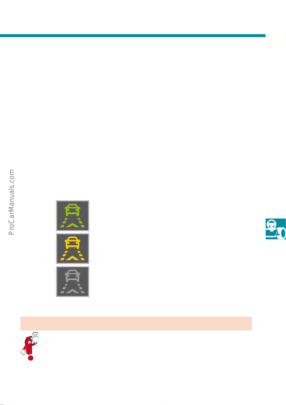
The ACC and Front Assist functions are housed in one control unit, although they are two separate components.
Front Assist works independently of the ACC status. It also remains active when the driver switches off the ACC.
Decisive for the functional readiness of Front Assist is the display of the status LEDs.
S488_082
Caution!
Front Assist does not intervene until just before a collision!
Interventions avoid accidents only in exceptional circumstances.
LED green: Front Assist switched on and ready to intervene.
LED yellow: Front Assist switched on but function sometimes impaired -
e.g. blocked sensor, overheated brakes, etc.
LED off: Front Assist switched off or malfunction.
47
Page 48

Driver assist systems
Overview of Front Assist co-functions
1. Vehicle conditioning
Vehicle conditioning works in a speed range of 5km/h to 210km/h. The vehicle is prepared for the driver to
perform an emergency stop:
● Prefill function (brake pads against brake discs).
● Hydraulic brake assist (HBA) trigger threshold adapted to highest sensitivity.
2. Driver alert
The driver alert is issued in a speed range from 30km/h to 210km/h. The driver is alerted in two stages:
● Preliminary warning: Warning sound and warning symbol in multifunction display.
● Main warning: Warning jolt.
3. Active brake interventions
Active brake interventions take place in a speed range from 5km/h to 210km/h. There are two types of operation:
● Target braking (braking pressure imparted by driver is boosted).
● Automatic partial braking (APB) in cases where the driver fails to react.
In a speed range from 5km/h to 30km/h, automatic partial braking is also referred to as
the "City Emergency Brake" function.
City Emergency Brake
48
In a speed range from 5km/h to 30km/h, automatic partial braking carries the name "City Emergency Brake". The
main difference compared with braking at speeds above 30km/h is that the city brake also reacts to stationary
vehicles. Furthermore, in the event of an immediate risk of collision there is no warning jolt, nor is the vehicle
2
decelerated (APB pilot stage). If a collision cannot be avoided, the vehicle is decelerated at a rate of 6.0m/s
.
Page 49
Overview of Front Assist and City Emergency Brake
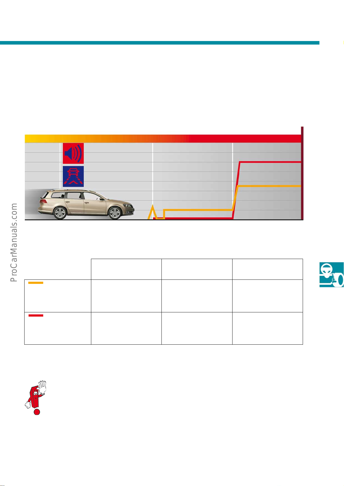
The following graph shows the sequence if a risk of collision is detected and the driver shows no reaction.
Risk of collision:
Marginal Raised
S488_084
HBA
sensitive
Warning jolt APB pilot stage APB main stage
HBA = Hydraulic Brake Assist; APB = Automatic Partial Braking
Marginal
Front Assist
Speed of obstacle greater
than 30km/h
risk of collision
Optical and acoustic warning
signal,
HBA changeover,
braking system prefilled
Raised
risk of collision
Warning jolt and APB pilot
stage
(Brake deceleration 1m/s
2
Highest
Highest
risk of collision
APB main stage
(Brake deceleration 3.5m/s
)
Collision
2
)
City Emergency Brake
Speed of obstacle less than
30km/h
If the driver intervenes by braking every time there is a risk of collision, the system supports him/her by
boosting the brake pressure. In doing so, the system attempts to keep any potential accident damage as
minimal as possible.
HBA changeover,
braking system prefilled
-APB main stage
(Brake deceleration 6.0m/s
2
)
49
Page 50
Driver assist systems
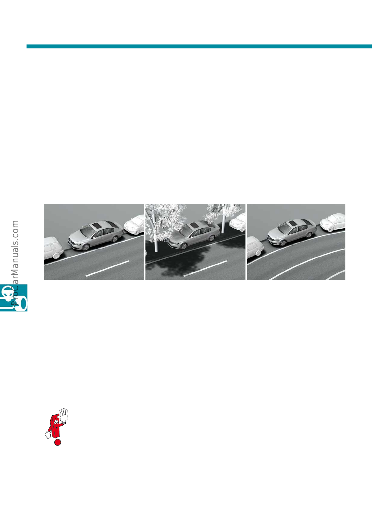
Park assist steering 2.0
The new park assist steering 2.0 represents a marked improvement over the previous park assist steering 1.0 and
also park assist steering 1.5. With this new semi-automatic parking system, parking in bays perpendicular to the
road is made possible and parking in even tighter parking spaces parallel to the road (kerb-side parking) has been
made much easier. It is now possible, for example, to
- park fully or partly on kerbs,
- park between trees and other obstacles and
- park on bends.
It is still possible to drive out of kerb-side parking spaces with this system and the process of entering or exiting can
be done in several stages. As the first parking system of its kind, park assist steering 2.0 includes active braking
support.
Further information about this new parking system can be found in
self-study programme no. 494 "Park assist steering 2.0".
S488_092
50
Page 51
Overview
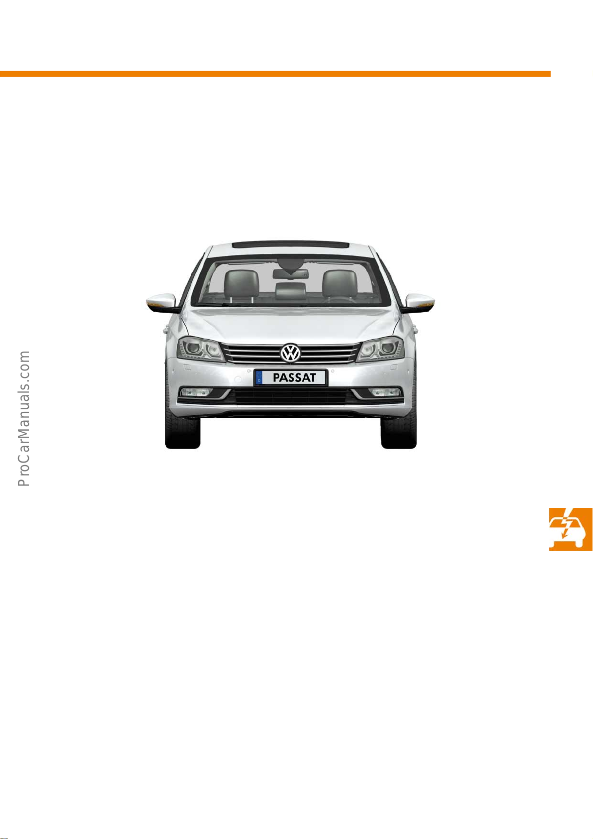
The Passat 2011 is equipped with state-of-the-art technology.
Electrical system
● KESSY with separate ignition
and engine start button
● Dynamic light assist,
optional
● 2nd generation park assist
steering, optional
S488_051
● Main beam assist
● Lane departure warning
with steering intervention
● Multifunction camera,
optional
● Control unit for terminal and
engine start control J942
● Heated windscreen, optional
51
Page 52
Electrical system
System overview
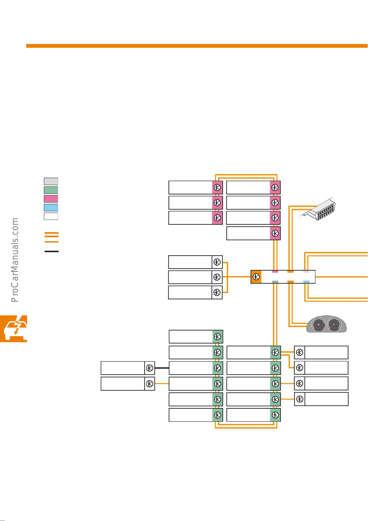
The lane departure warning system, previously used in the Phaeton and Touareg, is now utilised in the Passat 2011.
Also finding application in the VW brand are the new light assist systems 'dynamic light assist' (DLA) and 'main
beam assist'. The following diagram shows the largest possible network, with the Passat fully equipped.
Key
Powertrain CAN data bus
Convenience CAN data bus
Infotainment CAN data bus
Extended CAN data bus
LIN data bus
J364
J772
R78
J412
J525
R/J503
T16
CAN data bus line
LIN data bus line
Private bus
d - CAN diagnosis
k - CAN dash insert
* - or (not both)
J764
J453
R215
J245
J394
Y
J810
J301 G397
J393/J362
J527
J255
J519
J345
J386
J387
d
J533
k
J285
J400
J926
J927
52
J605
J501
Page 53
J500
J623
J234
E313
J250
CX1
J367
J428
J502
J540
J104
J743
J791/J446*
J492
J844
R242
J745
J668J667
S488_010
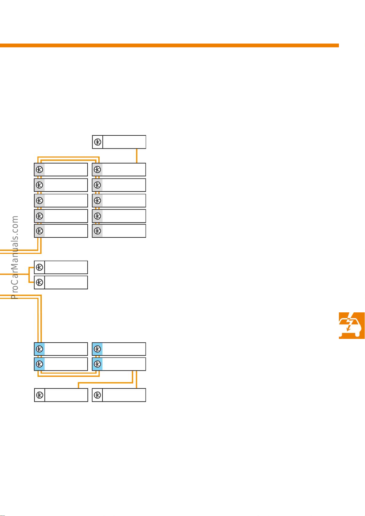
Key
CX1 - Alternator
E313 - Selector lever
G397- Rain and light sensor
J104 - ABS control unit
J234 - Airbag control unit
J245 - Sliding sunroof control unit
J250- Electronically controlled damping control unit
J255 - Climatronic control unit
J285 - Control unit in dash panel insert
J301 - Air conditioning system control unit
J345 - Trailer detector control unit
J362 - Immobilizer control unit
J364 - Auxiliary heater control unit
J367 - Battery monitor control unit
J386 - Driver door control unit
J387 - Front passenger door control unit
J393 - Convenience system central control unit
J394 - Roof roller blind control unit
J400- Wiper motor control unit
J412 - Mobile telephone operating electronics control unit
J428- Control unit for adaptive cruise control
J446 - Parking aid control unit
J453 - Multifunction steering wheel control unit
J492- Four-wheel drive control unit
J500- Power steering control unit
J501 - Multifunction unit control unit
J502- Tyre pressure monitor control unit
J503- Control unit with display for radio and
navigation system
J519 - Onboard supply control unit
J525 - Digital sound package control unit
J527 - Steering column electronics control unit
J533 - Data bus diagnosis interface (gateway)
J540- Control unit for electromechanical parking brake
J605- Rear lid control unit
J623 - Engine control unit
J667 - Power output module for left headlight
J668 - Power output module for right headlight
J743 - Mechatronic unit for direct shift gearbox
J745 - Cornering light and headlight range control unit
J764 - Electronic steering column lock control unit
J772 - Reversing camera system control unit
J791 - Control unit for park assist steering
J810 - Driver seat adjustment control unit
J844 - Main beam assist control unit
(except with R242 and J745)
J926 - Rear door control unit, driver side
J927 - Rear door control unit, front passenger side
R78 - TV tuner
R215 - Interface for external multimedia devices
R242- Front camera for driver assist systems
(except with J844)
T16 - 16-pin connector
Y - Analogue clock
53
Page 54
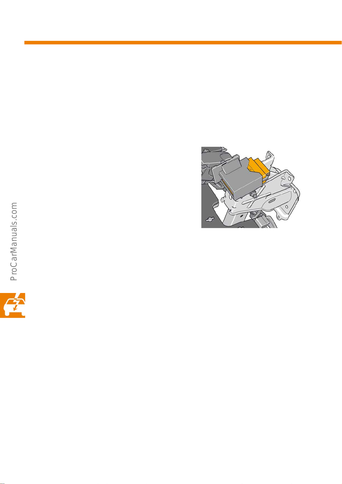
Electrical system
The control unit for terminal and engine start control
For the first time, a terminal control unit finds application in the new Passat. It serves on one hand to actuate the
terminals in advance as a link between the onboard supply control unit and the control elements of the electronic
ignition lock. On the other hand, it serves to emulate the terminals for the newly added ignition starter button (ISB).
The terminal control unit is only installed in conjunction with KESSY.
The terminal control unit can be found in a separate
housing holder above the pedal bracket in the driver's
footwell. The terminal control unit has a discrete
connection to the onboard supply control unit. The
control unit is permanently coded for automatic start
(pin coding). For the Passat, provision has been made
for two functions: with and without start/stop system.
Diagnosis
If the terminal control unit should fail while the vehicle is in motion, terminal 15 will continue to be supplied as an
emergency running measure until engine speed is zero. Thereafter, ignition is switched off and emergency running
is activated both on the hardware and software side (internal terminal CU measure). This means that the terminal
request from the electronic ignition lock is enabled, thereby allowing the vehicle to be operated through this switch.
The ISB will no longer work and its light is switched off as with all other implausible ignition starter button problems.
The engine control unit interrogates the existing potential for plausibility just before the terminal 50 request from
the terminal control unit via the diagnosis wire (terminal 50 R for "read back") for starter actuation. In the event of
implausibility, the engine ECU ceases its attempt to start the engine. The onboard supply control unit (OSCU)
receives this information at the same time.
Both input pins of the ISB must have the same signal so that the operational request from the ISB is accepted by the
terminal control unit. Inputs open means ISB not pressed; inputs to earth means ISB pressed. In addition to the
information (no fault present; all conditions met for starting), diagnoses are also transported via the path "fault
information" from terminal CU to OSCU (2 of 3 status lines currently in use). There are currently two possible fault
messages: "Control unit faulty" and "ISB faulty".
S488_132
54
Page 55
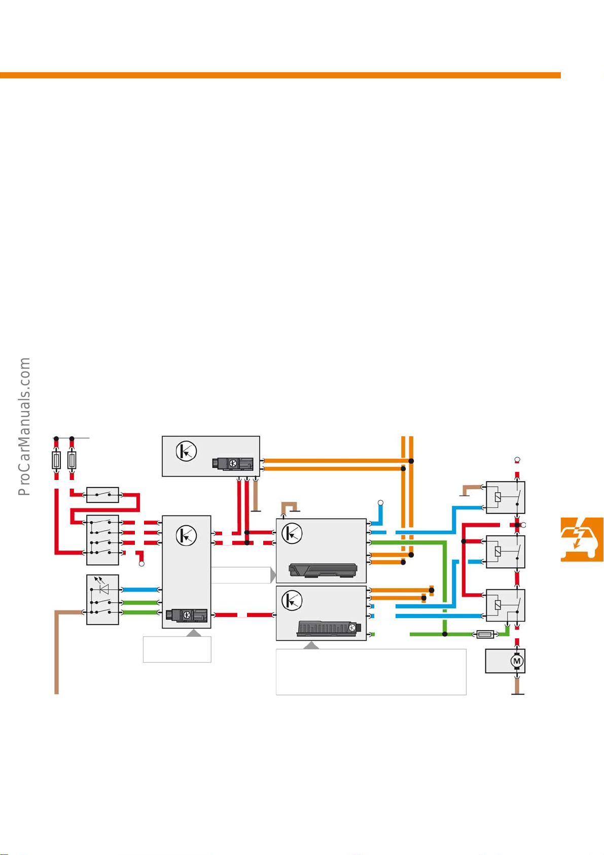
Function
The driver can control the vehicle functions at the same time from the electric ignition lock or/and from the ignition
starter button. Terminals S, 15 and 50 from the electric ignition lock are just passed through in the terminal CU.
Terminals S and 15 are generated electronically by the terminal CU due to the request from the ISB. These carry a
steady signal upon active request. The term. 50 request during automatic start represents a 200ms square wave
impulse from the terminal CU to the engine control unit, irrespective of how long the ISB is pressed.
If the engine control unit has information about the framework conditions, such as the PN signal on automatic
vehicles (selector lever in P or N position) and the brake signal, the engine control unit actuates both its starter
relays (SST1, SST2). On vehicles with manual gearbox, the clutch actuation signal (interlock) serves as a condition
for input.
Functional diagram
B B
ESL
As
Cs
S
EIL
ISB
Key
A-terminal 15
As - terminal 15s
B-terminal 30
C-terminal 50
Cs - terminal 50s
P-terminal P
P
Coding
J527
J942
terminal
CU
SMLS
Ks
Ka
ST
50_SMLS
C
PN/interlock
J519
OSCU
CAN
Te rm . 75
CAN
J623
ECU
Kc
● PN (automatic gearbox), interlock
(manual gearbox)
● Neutral gear sensor (NGS)*
● Brake signal (BLS, BTS)
S-terminal S
Ks - terminal CU_S (request from J942)
Ka - terminal CU_15 (request from J942)
Kc - terminal CU_50 (request from J942)
ST - Status lines with fault and status information
SST - Start control
* - On vehicles with start/stop system
A
SST1
SST2
Te rm . 50 R
S488_134
B
A
C
55
Page 56
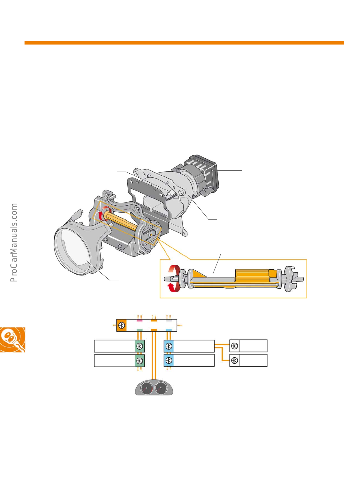
Convenience electronics
Dynamic light assist (DLA)
A new generation of dynamic light assist is used in the Passat 2011 in combination with xenon headlights. It works in
the same way as the headlights on the Touareg, though differs in its technical makeup due to different
manufacturers. The headlight installed in the Passat features a rotating shutter with four shield profiles. In addition,
there is a shutter range with variable light shield (masked permanent main beam).
Headlight
S488_094
Networking
D3S
Power electronics
Reflector
Masking area (DLA)
Lens
Shutter with shields
J533
56
J519
J527
Key
J519 - Onboard supply control unit
J527 - Steering column electronics control unit
J533 - Data bus diagnosis interface (gateway)
J285 - Control unit in dash panel insert
J667 - Power output module for left headlight
J745
R242
J285
J668 - Power output module for right headlight
J745 - Cornering light and headlight
range control unit
R242- Front camera for driver assist systems
J667
J668
S488_042
Page 57
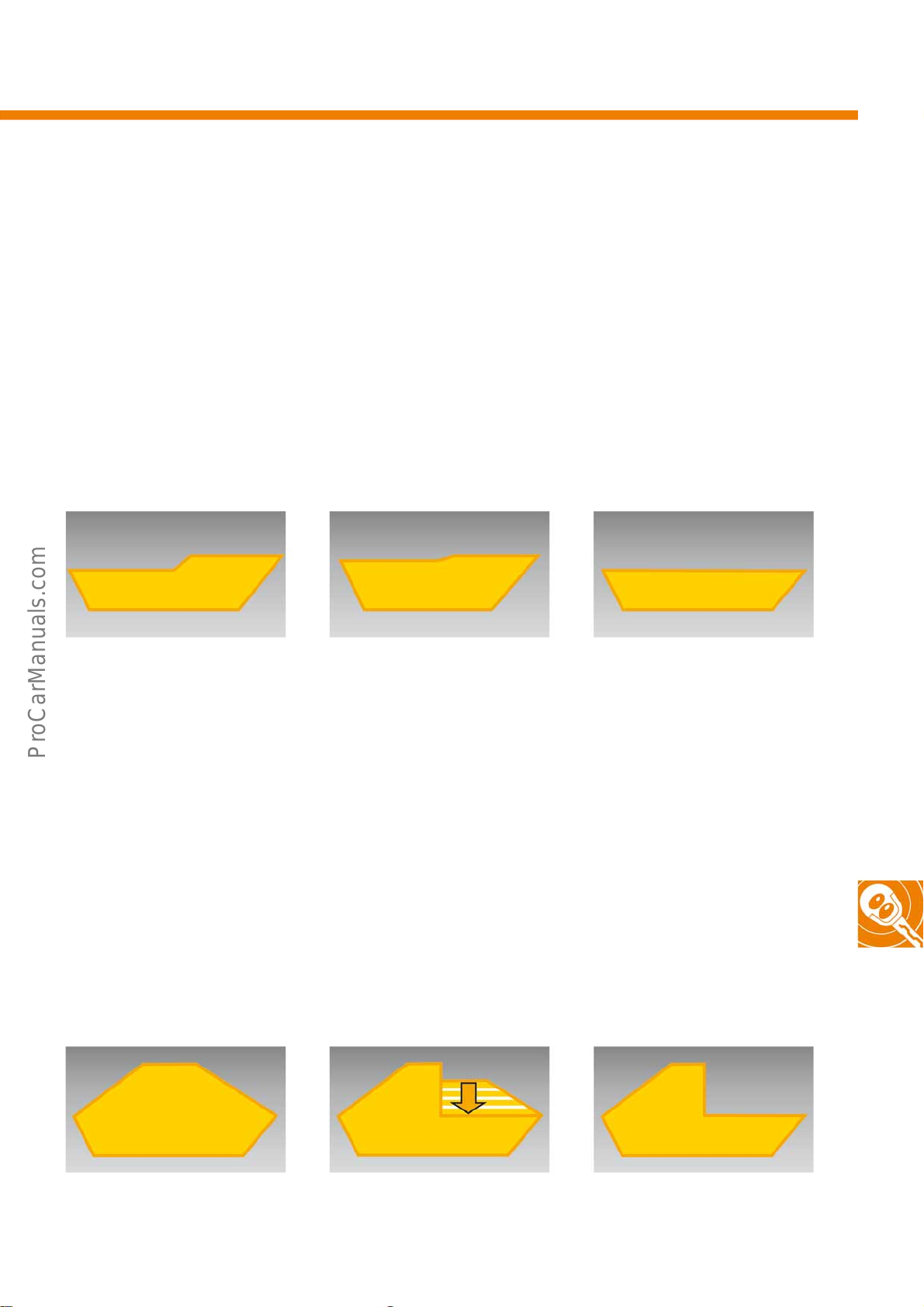
Shield positions
Main road light, motorway light, urban light and touring mode
These light cone patterns (from a vehicle for right-hand traffic) are made possible by three different shield profiles
on one shutter. Depending on the speed of the vehicle or menu setting, the shutter toggles between the positions for
main road, motorway, urban (not including xenon headlight function with masked permanent main beam) and
touring mode. In touring mode, there is no main road (dipped beam), motorway and dynamic cornering light. The
following light cone patterns are projected against a wall from a distance of approx. 10m (full illumination):
Main road light
(up to 110km/h)
Motorway light
(from 110km/h)
Left light cone raised
Urban light (10-45km/h)
Touring mode (static)
S488_096
Maximum dipping of light cone
Main beam and masking position
The masking range on the shutter is used in conjunction with a gradual transition to main beam for dynamic light
assist. If the system does not detect any vehicles in the dazzle range of the light cone, the shutter is turned to the
non-dipped position. The light cone is therefore unmasked. If a vehicle travelling ahead approaches the light cone,
the large shield on the shutter is turned into the light cone dynamically. In this way, only the light that could dazzle
oncoming traffic or the vehicle travelling ahead is "dipped". The remaining field of light on the left-hand side is
swiveled away from oncoming traffic to the left and "dipped" to the maximum range available for the main road
setting. The DLA becomes active from 60km/h and remains this way even if the vehicle is slowed down to 55km/h.
Main beam (unmasked position) Dynamic range* Maximum "dipped" range*
*Left headlight (mirror image on right headlight)Light cones overlap
S488_098
57
Page 58
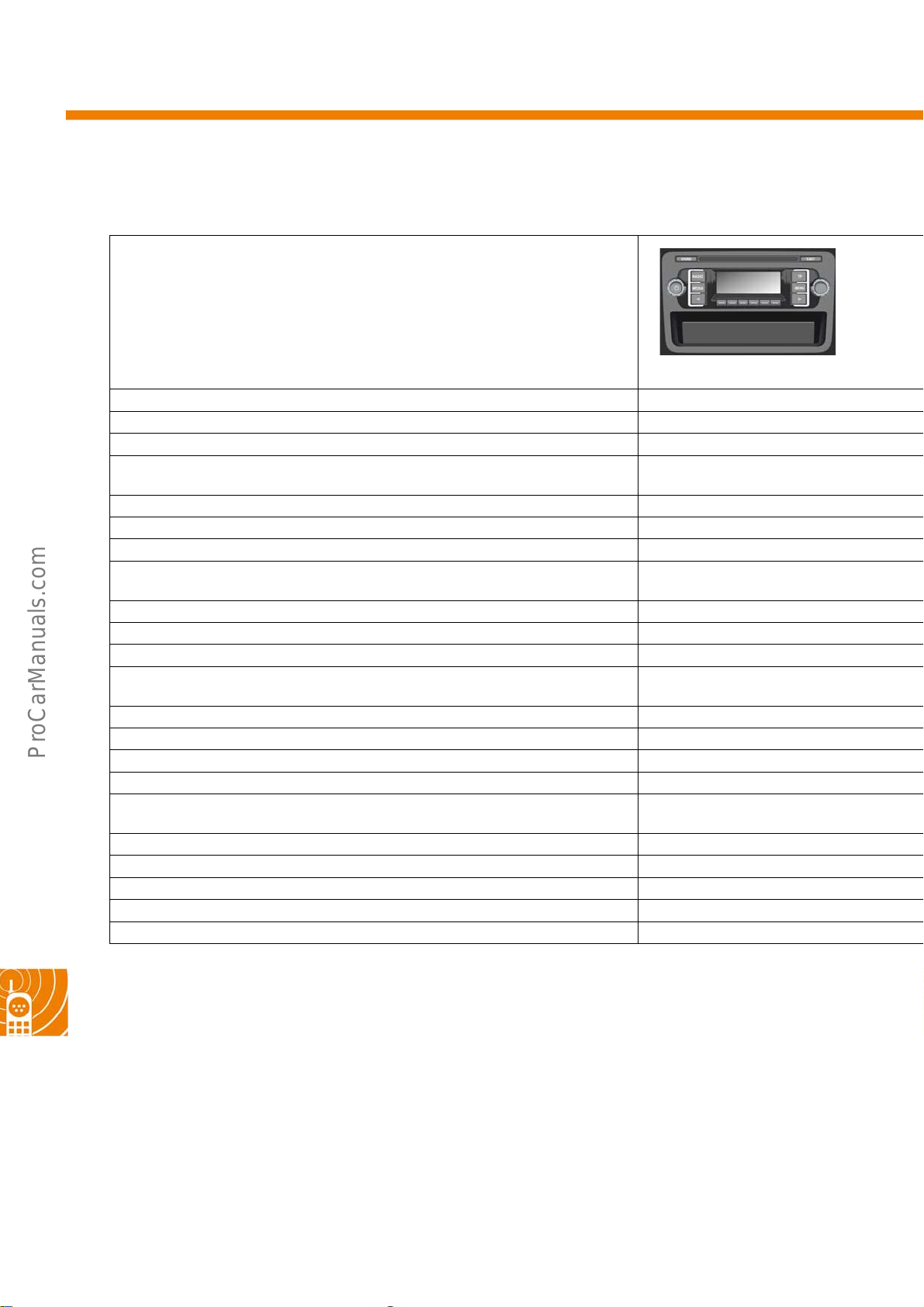
Radio, navigation and telephone
The radios
Technical d a t a
Display Monochrome, 122 x 36 pixels
Touch sensitive (touchscreen)
AM, FM, TP and RDS reception (basic tuner) ●
AM, FM, TP and RDS reception (diversity tuner)
Integrated DAB tuner (digital radio)
Integrated disc drive CD
Integrated SD/SDHC memory card reader
Media support CD and MP3 audio data
Audio input interface (AUX-IN) Can be retrofitted
Telephone interface for hands-free device ● (Mono-channel only)
Interface for connecting a reversing camera
Loudspeaker output stages 4x20 watt output
(2 or 4 loudspeakers can be connected)
Control of external CD changer ● (No MP, WMA3)
Control of external amplifier
Connection of external media devices (USB, mini USB, iPod)
Speed-dependent volume adjustment ●
Brightness of display light can be regulated
independently of interior light in vehicle
Self-diagnosis and loudspeaker diagnosis ●
Service test mode ●
Optical parking system (OPS)
Air conditioning information
For further information, see self-study programme no. 404
RCD 210
●
●
58
* Discontinued from model year 2012
** DAB version shown
*** EU version without DAB shown
Page 59
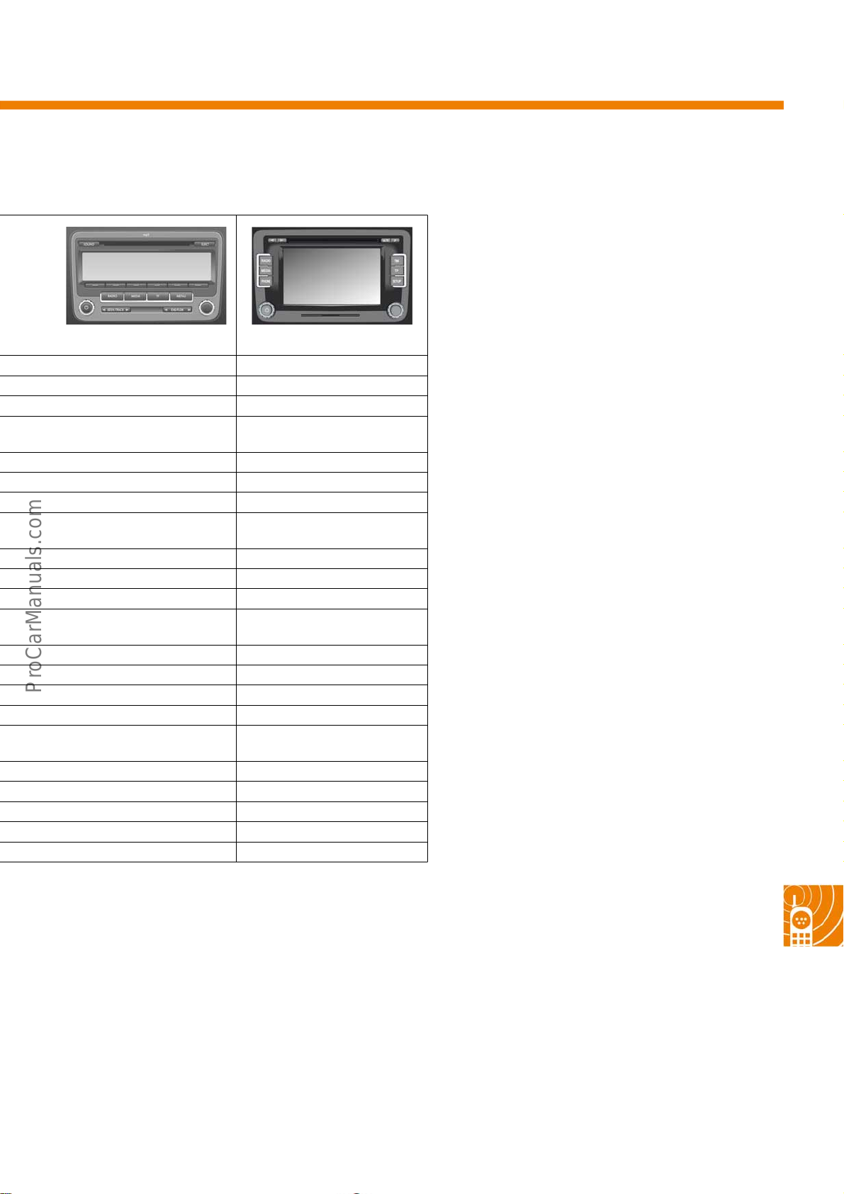
RCD 310** RCD 510***
Monochrome, 302 x 45 pixels 6.5", 400 x 240 pixels
●
●●
Depending on equipment Depending on equipment
CD CD (6-disc changer)
●
CD, MP3 and
WMA audio files
●●
●●
●●
●●
●●
●●
●●
CD, MP3 and
WMA audio files
Depending on equipment
● (No MP3, WMA)*
●●
●●
●●
●●
no. 417 no. 423
59
Page 60
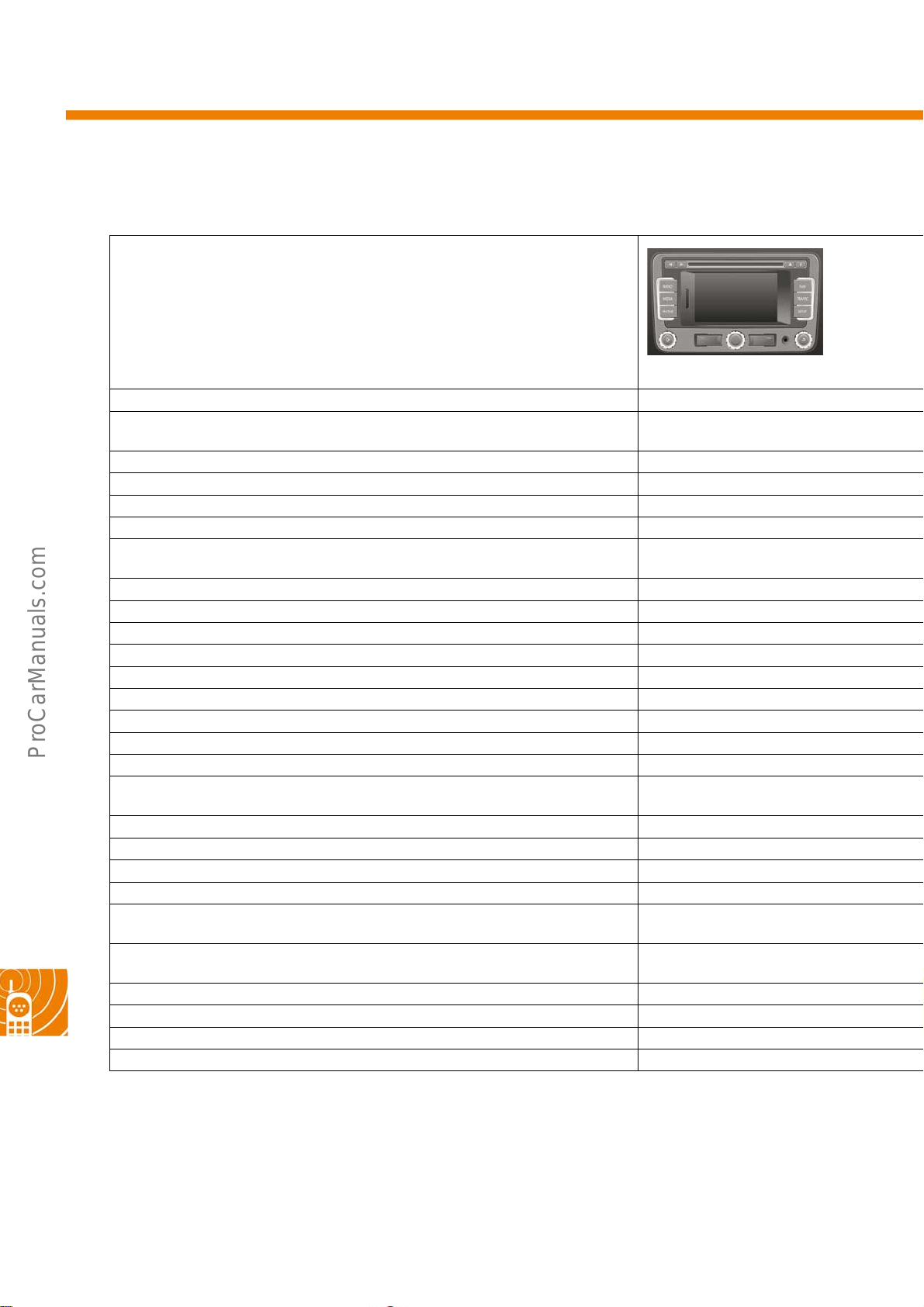
Radio, navigation and telephone
The radio-navigation systems
Technical d a t a
Display 5", 400 x 240 pixels
Touch sensitive (touchscreen) ●
AM, FM, TP and RDS reception (diversity tuner) ●
Integrated DAB tuner (digital radio) Optional
Integrated disc drive CD
Integrated SD/SDHC memory card reader ●
Media support CD, MP3 and
Audio input interface (AUX-IN) External and front
Telephone preparation support ●/+Bluetooth internal
Interface for connecting a reversing camera ●
Loudspeaker output stages 4x20 watt output ●
Control of external CD changer ●
Control of external amplifier ●
Connection of external media devices (USB, mini USB, iPod) ●
Can be combined with TV-tuner
Speed-dependent volume adjustment ●
Brightness of display light can be regulated
independently of interior light in vehicle
Self-diagnosis and loudspeaker diagnosis ●
Service test mode ●
Optical parking system (OPS) ●
Air conditioning information ●
Navigation function with map,
integrated driving symbols and voice
Integrated storage media Flash memory***
Navigation data Internal memory
Navigation data update via SD card**
Traffic sign display ●
For further information, see self-study programme no. 493
RNS 315
WMA audio files
●
●
(6GB/4GB NAR)
60
* The hard-disc is partitioned: 20GB are available for media data,
10GB are reserved for navigational data.
** The purchased SD card can be used for any navigation unit, though it is only coupled to the specific device once
updated and can only be used with this device.
*** Can only be used for navigational data.
Page 61
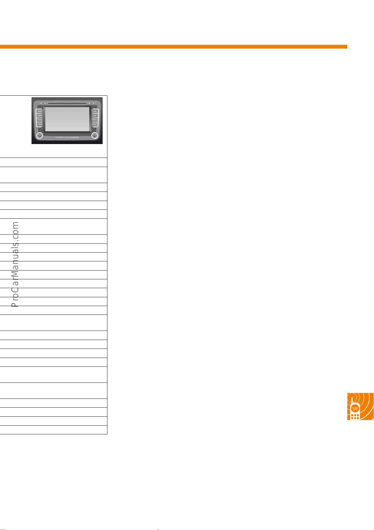
RNS 510
6.5", 800 x 480 pixels
●
●
DVD
●
CD, MP3, WMA audio,
DVD formats
External
●
●
●
●
●
●
●
●
●
●
●
●
●
Hard-disc 30GB*
Hard-disc*
DVD
●
no. 423
61
Page 62
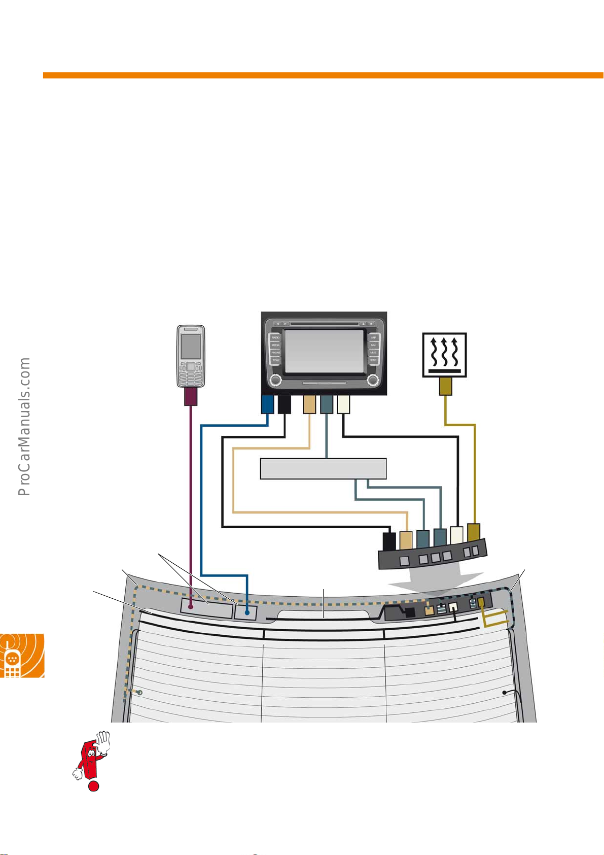
Radio, navigation and telephone
The aerial concept
Passat saloon
On the saloon, all of the aerials are integrated in the rear window. The entire heating wire structure is part of the
FM and TV signal aerial system. The signals are separated electronically according to TV1, TV2 and FM1, FM2.
The GSM/UMTS and GPS aerials are designed as separate modules and are clipped onto the rear window. The
aerial connections all run via the aerial module, which has the corresponding impedance transformer. Depending
on the signals required, the aerial module has three mechanical configurations and nine versions (part numbers).
The diagram shows the maximum equipment.
Auxiliary
heater
S488_118
GSM/UMTS
Modules
FM2 /T V2
AM
K
D
GPS
GCA IB
TV tuner
DAB
K
B
H
G
I
A
Aerial module
FM1/ T V1
62
Left Right
Further information on this aerial concept can be found in self-study programme
no. 342 "Radio systems 2006".
Page 63
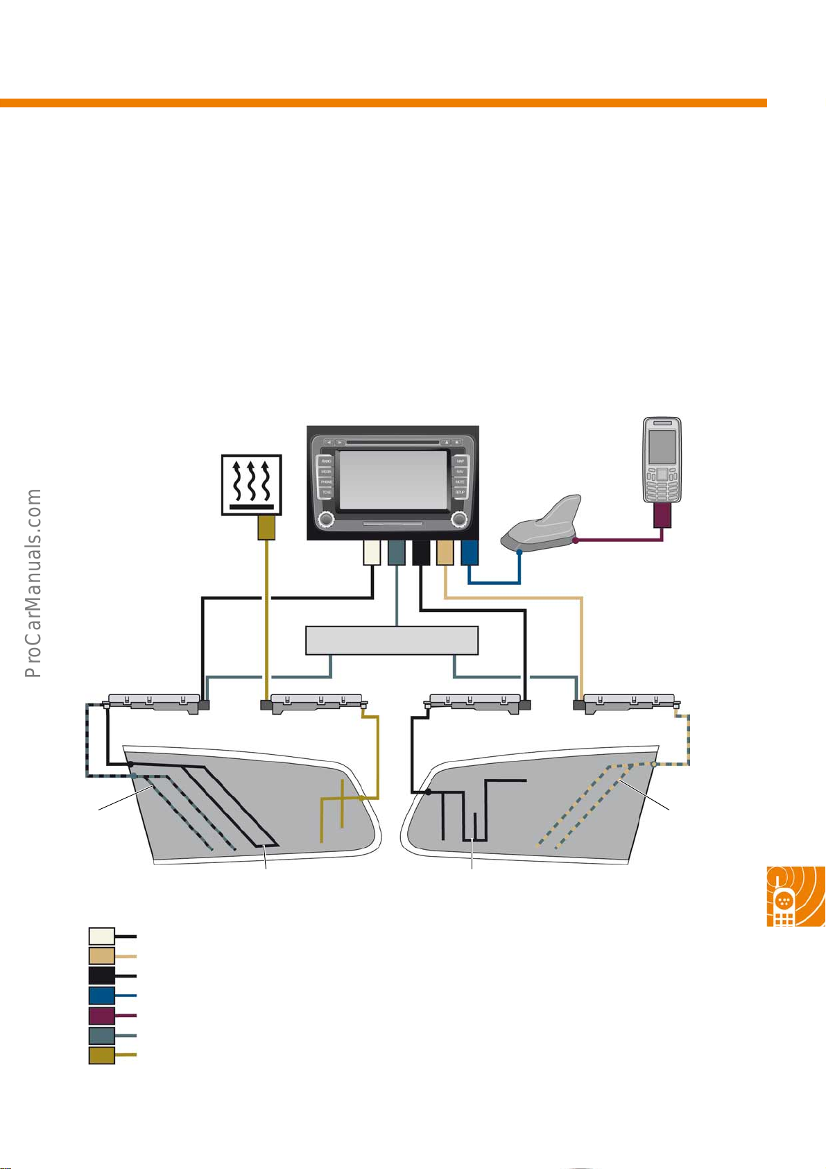
Passat estate
On the estate model, the radio aerials and the aerials for radio remote control (RRC) of the auxiliary heater are
integrated in both rear side windows. In addition to this, it features a roof aerial for GPS and/or GSM/UMTS.
Depending on the signals required, the impedance transformer is available in different versions. The diagram
shows the maximum equipment.
Auxiliary
heater
S488_116
K
GA CIB
GSM/UMTS,
GPS
D
Impedance
transformer
AM/FM1/TV1 D AB FM2/TV2
FM1/ T V1
Left
Key:
B
I
A
C
D
G/H
K
FM1 /AM
FM2 ( Diver sity)
DAB
GPS
GSM/UMTS
TV
Auxiliary heater
RRC
auxiliary heater
AM
TV tuner
DAB
FM2/ TV2
Right
63
Page 64
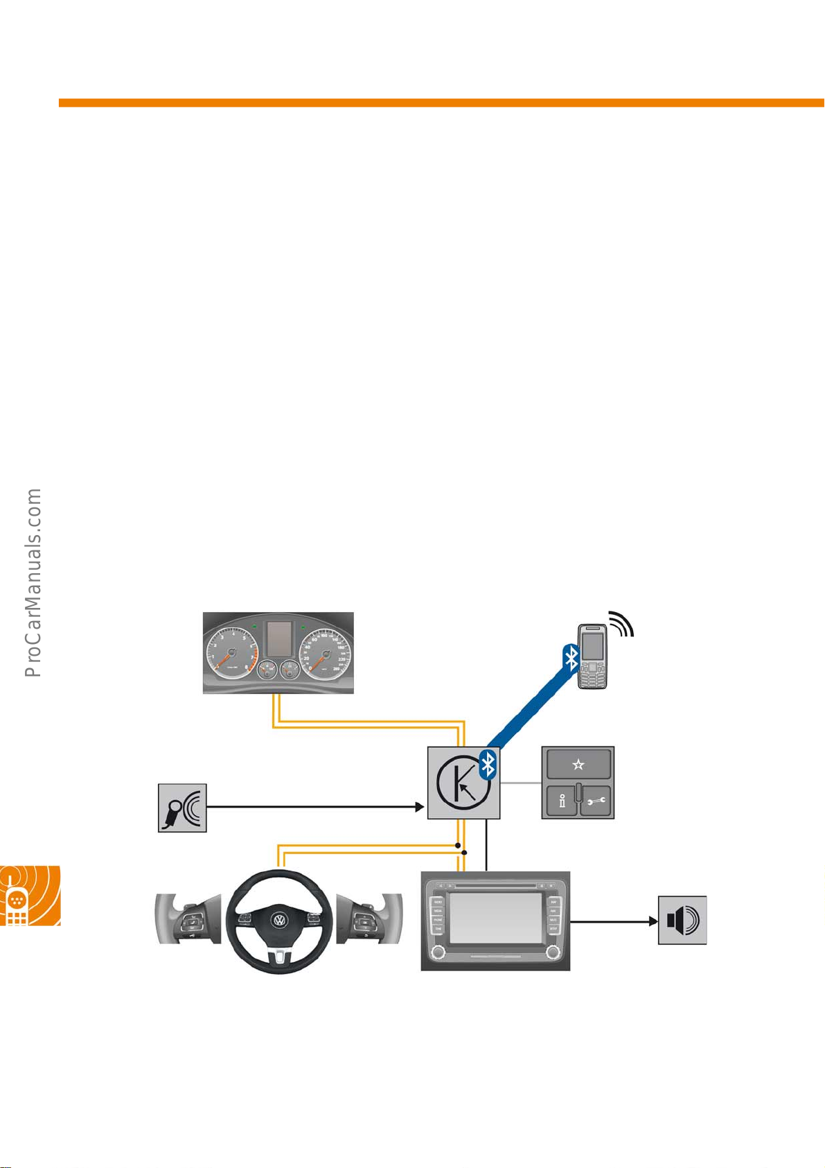
Radio, navigation and telephone
Universal cellphone preparation (UHV)
High (9ZB)
On the UHV High system, the cellphone is connected exclusively via Bluetooth. In this case, only the voice data is
transferred between the microphone, the control unit for cellphone operating electronics (J412) and the
loudspeaker system of the vehicle. Communication with the GMS/UMTS network is via the cellphone aerial. This
UHV features the following functions:
Internal functions:
● Hands-free profile (HFP 1.5)
● BT audio streaming (A2DP 1.2) and control
Microphone in
roof unit
Convenience control
dash panel insert
(MFD+)
CAN**
J412
Control unit for
cellphone operating electronics
External functions:
● Convenience radio/sat nav operation
● Multifunction display (MFD)
● Multifunction steering wheel, optional
● 3 button module in roof unit
GSM/
UMTS*
P
D
2
A
P,
F
H
3 button
module
64
Multifunction steering
wheel, optional
** Always stands for signal transfer via
CAN data bus, irrespective of bus designation and
interconnected gateway.
Loudspeaker
S488_110
RCD/RNS
* Depending on cellphone/SIM card
Page 65
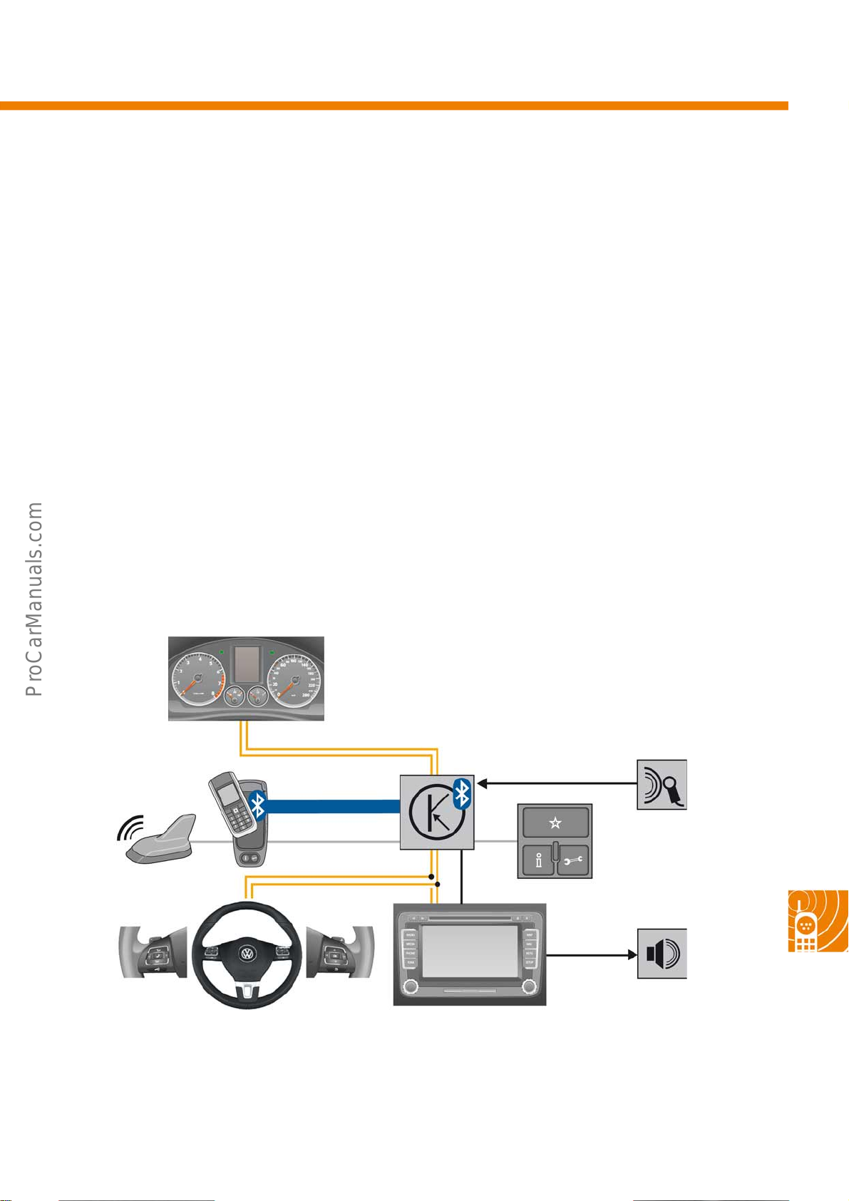
High "baseplate" (9ZA)
Compared with the UHV High (9ZB), this UHV features a baseplate. This serves to mount the telephone-specific
charging cradle via which connection to the roof aerial takes place. When the cellphone is connected to the vehicle
via the charging cradle, any radio communication (GSM/UMTS) from the vehicle is processed via the roof aerial.
This UHV also features the following functions:
Internal functions:
● Hands-free profile (HFP 1.5)
● BT audio streaming (A2DP 1.2) and
control (AVRCP 1.3)
● Voice-controlled operation (G2P/TTS)
● SMS speaking
Charging cradle with
aerial connection
to roof aerial
GSM/
UMTS*
Convenience control
dash panel insert
(MFD+)
CAN**
HFP, A2DP
External functions:
● Convenience radio/sat nav operation
● Multifunction display (MFD)
● Multifunction steering wheel, optional
● 3 button module in roof unit
● Baseplate for mounting special
phone holder
● External aerial connection via phone
holder
Microphone in
roof unit
J412
3 button
module
Multifunction steering
wheel, optional
** Always stands for signal transfer via
CAN data bus, irrespective of bus designation and
interconnected gateway.
Loudspeaker
S488_112
RCD/RNS
* Depending on cellphone/SIM card
65
Page 66
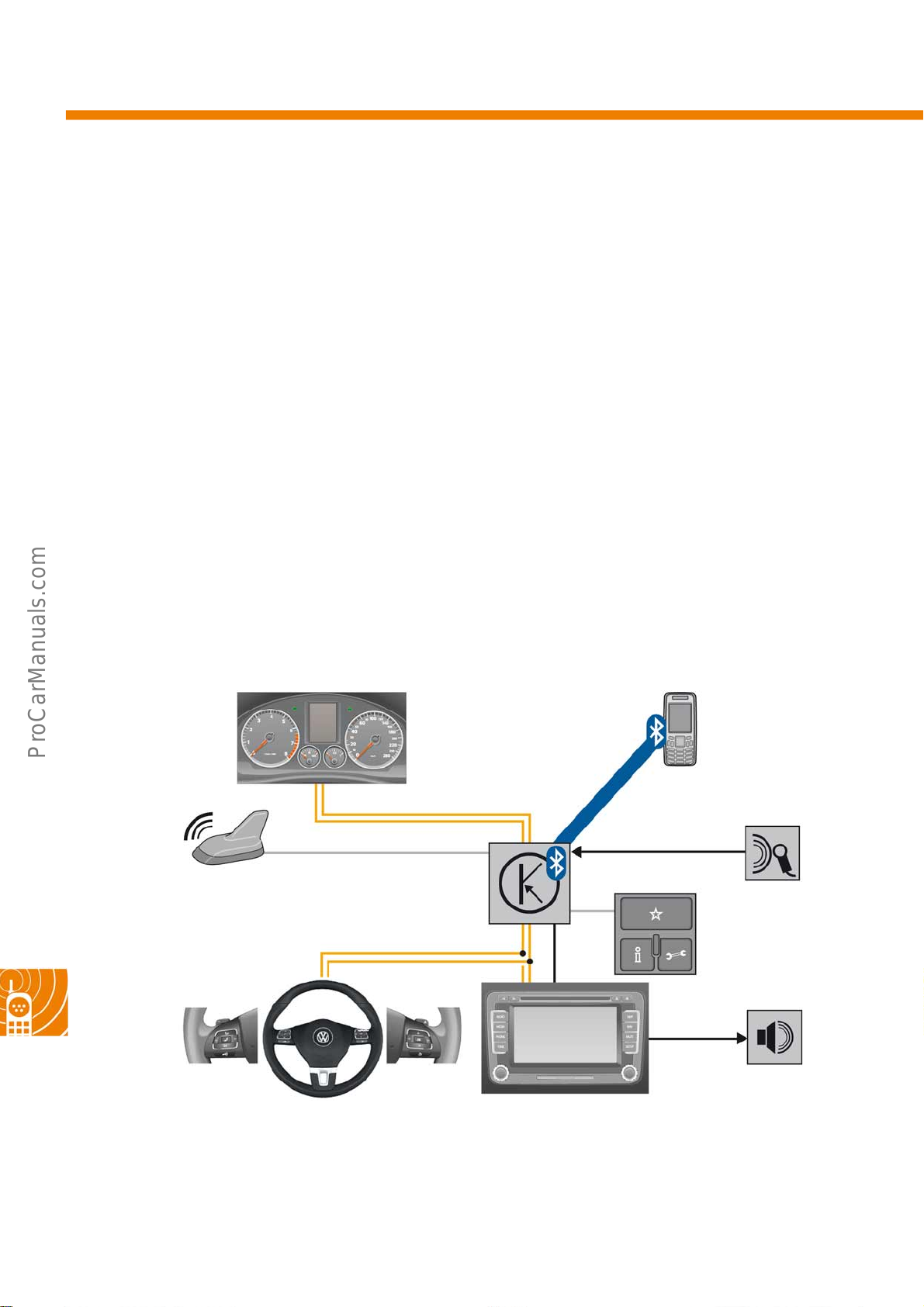
Radio, navigation and telephone
Premium (9ZU)
The UHV Premium distinguishes itself from the UHV High "baseplate" by the internal GSM/UMTS module. A
connection between the cellphone and the vehicle is not made (charger cradle optional) as the internal UHV
module has access to the telephone data via Bluetooth by way of the Sim Access Profile (SAP). In this way, any
radio communications (apart from Bluetooth) outside the vehicle are processed via the integrated GSM/UMTS
module and the roof aerial. This UHV also features the following functions:
Internal functions:
● Hands-free profile (HFP 1.5)
● BT audio streaming (A2DP 1.2) and
control (AVRCP)
● Voice-controlled operation (G2P/TTS)
● Sim Access Profile (SAP 1.0)
● SMS reading, writing and speaking
GSM/
UMTS
External functions:
● Convenience radio/sat nav operation
● Multifunction display (MFD) with Highline or
● Multifunction steering wheel
● 3-button module in roof unit
● Charger cradle
● External aerial connection via control unit
Convenience control
dash panel insert
(Highline/Premium)
CAN**
Premium line dash panel insert
P
,
P
D
A
2
S
A
,
P
F
H
Microphone in
roof unit
66
Roof aerial
Multifunction
steering wheel
** Always stands for signal transfer via
CAN data bus, irrespective of bus designation and
interconnected gateway.
GSM/UMTS module
Internal
3 button
module
Loudspeaker
S488_114
RCD/RNS
Page 67
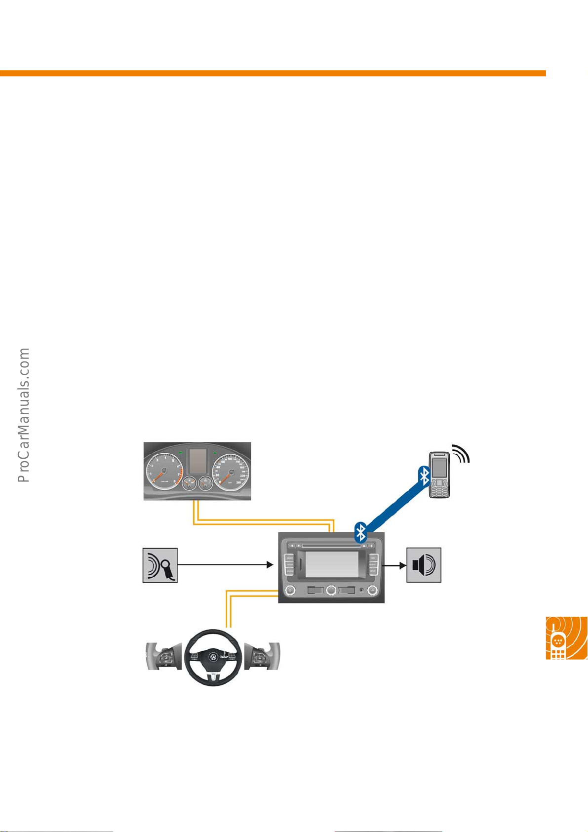
Internal RNS315 (9ZI)
The internal UHV of the RNS315 operates without additional external UHV control units. The cellphone is
connected exclusively via Bluetooth. Only the voice data and command instructions are transferred in this case.
GSM communication with the network provider is via the aerial in the cellphone. This UHV features the following
functions:
Internal functions:
● Hands-free profile (HFP 1.5)
● BT audio streaming (A2DP 1.2) and control
Microphone in
roof unit
External functions:
● Convenience radio/sat nav operation
● Multifunction steering wheel, optional
Convenience control dash
panel insert
(MFD+)
CAN**
GSM/
UMTS*
P
D
2
A
,
P
F
H
Loudspeaker
Multifunction
steering wheel,
optional
** Always stands for signal transfer via
CAN data bus, irrespective of bus designation and
interconnected gateway.
S488_120
RNS315
* Depending on cellphone/SIM card
67
Page 68
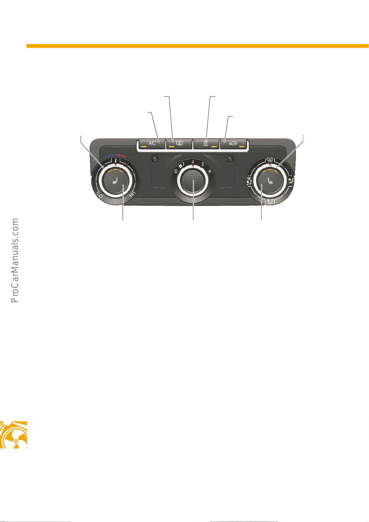
Heating and air conditioning
Air conditioning
Rear window heater button Instant heat button
AC button
Rotary switch for
temperature control
for auxiliary coolant heater
Air circulation button
Rotary switch for
air distribution
S488_059
Operation
The air conditioning system features manual controls.
Depending on the equipment, there are different
control and display units. The illustration above shows
the maximum equipment. Depending on the
equipment, an instant heat button for the coolant
supplementary heater or a button for activation of the
windscreen heater may be installed.
The control elements are equipped with LEDs for
visual feedback. They indicate whether a function is
active or at what output stage a function is operating.
Front left seat
heating button
Rotary switch for
fresh air blower
Unlike the familiar Climatic system, the interior
temperature sensor and the temperature sensors at
the air vents have been discontinued. Therefore, no
provision is made on the AC system for a fixed
temperature selection in °C. Instead, the interior
temperature is regulated manually using the rotary
temperature control switch. This rotary switch can be
adjusted without increments between HI and LO.
Adjustment of the temperature flap on the AC unit is
still performed by servomotors with feedback
potentiometers.
Supplementary heater and PTC heater are not
deactivated when the AC unit is switched off.
Front right seat
heating button
68
Page 69
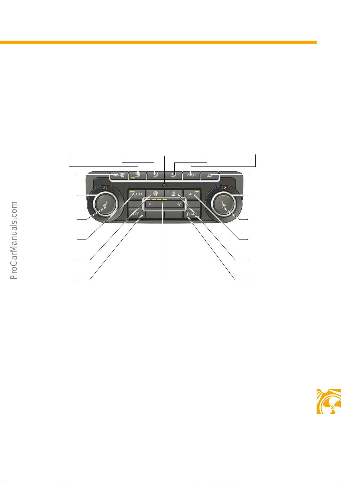
2-zone Climatronic
The 2-zone Climatronic features an AC unit with two temperature flaps that can be adjusted independently of each
other. In this way, the interior temperature on the driver side and front passenger side can be selected separately.
Head vent Torso vent
Defrost
Left temperature
rotary control
Front left seat
heating button
Auto high/low
Windscreen heater
OFF
Unvented interior
sensor
S488_003
Rocker switch
for fresh air blower
Footwell vent
Air recirc./
auto air recirc.
Heated rear window
Right temperature
rotary control
Front right seat
heating button
AC ON/OFF
Instant heat button
2-zone
synchronisation
Operating and display unit
Depending on the set values and the environmental
conditions, such as the outside temperature, the
temperature, air quantity and also air distribution are
regulated automatically by the Climatronic system.
Manual operation of the Climatronic system is still
possible.
LEDs in the individual function buttons give feedback
regarding the current settings of the selected
functions. This information can be displayed as a
popup in the radio and radio-navigation unit as well.
Supplementary heater and PTC heater are not
deactivated when the AC unit is switched off.
69
Page 70
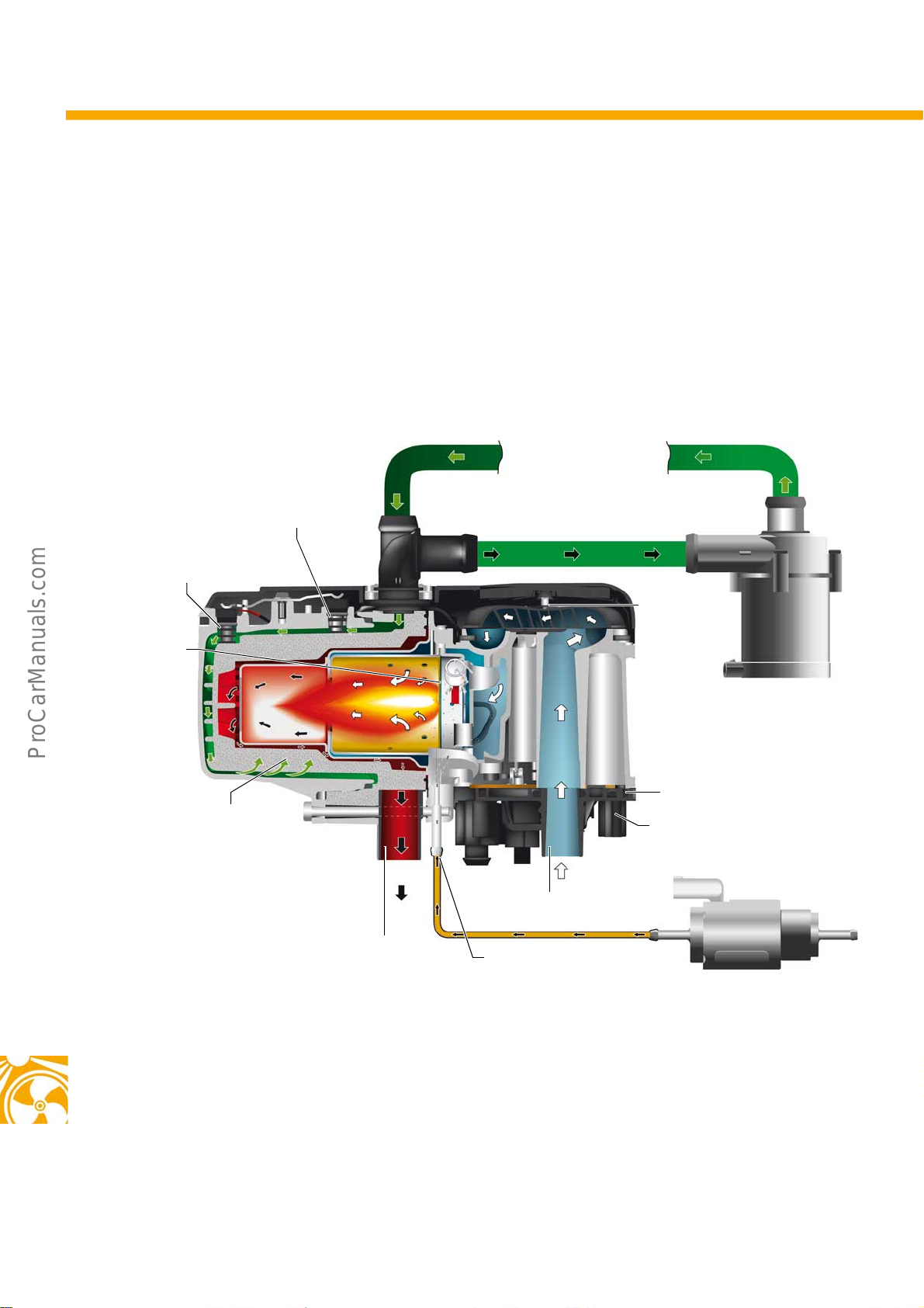
Heating and air conditioning
Thermo Top fleece auxiliary coolant heater
On vehicles with diesel engines, the new ThermoTopfleece from WEBASTO is used as an auxiliary coolant heater
and as a supplementary heater. The difference to ThermoTopV is that the new heater is equipped with a fleece
burner. There are no changes in operation, fitting location or functions.
On petrol engine vehicles, ThermoTopV with venturi burner will continue to be installed until further notice.
Temperature sensor
Overheating sensor
Metal fleece
Heat exchanger
Exhaust gas outlet
Coolant inlet and outlet
Combustion
air blower
Control unit
Electrical connection
Combustion air inlet
Fuel inlet
S488_049
70
Page 71

Notes
71
Page 72
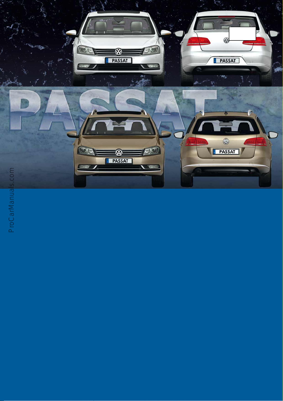
488
© VOLKSWAGEN AG, Wolfsburg
All rights and rights to make technical alterations reserved.
000.2812.48.20 Technical status 12.2010
Volkswagen AG
After Sales Qualification
Service Training VSQ-1
Brieffach 1995
D-38436 Wolfsburg
❀ This paper was manufactured from pulp that was bleached without the use of chlorine.
 Loading...