

Page 1

Service Training
Self-Study Programme 453
For the T5 2010
Commercial
Vehicles
Page 2

The T5 from Volkswagen Commercial Vehicles
Series production of the first Volkswagen Transporter
started in March 1950. An initial production of
10 vehicles per day quickly developed into one of the
most successful careers for an automobile, and one
which laid the foundation for a new vehicle segment.
Multivan and Caravelle also founded a new vehicle
segment in which they have continued to set new
standards right down to the present day.
Today, as in the past, the Volkswagen Commercial
Vehicles brand stands for innovative technology and
a product range that is tailored to requirements. At
the same time, e.g. TDI®, DSG® and 4MOTION®
represent unique technical solutions that are only
available in this segment in models from Volkswagen
Commercial Vehicles.
S453_002
The T5 2010 will be available in the following equipment lines:
Transporter: Panel van, window van, chassis, platform van and back-to-back cab
Caravelle: Trendline and Comfortline
California: Beach and Comfortline
Multivan: Startline, Comfortline, Highline and PanAmericana
The self-study programme shows
the design and function of new
developments!
The content is not updated.
For current inspection and setting instructions, and
workshop manuals, please refer to the service
literature that is provided.
Important
Note
2
Page 3

At a glance
Introduction . . . . . . . . . . . . . . . . . . . . . . . . . . . . . . . . . . . . . . . . . . . . . . . . . . . . . 4
The model family of the T5 2010 . . . . . . . . . . . . . . . . . . . . . . . . . . . . . . . . . . . . . 4
Technical data . . . . . . . . . . . . . . . . . . . . . . . . . . . . . . . . . . . . . . . . . . . . . . . . . . . . 6
Body . . . . . . . . . . . . . . . . . . . . . . . . . . . . . . . . . . . . . . . . . . . . . . . . . . . . . . . . . . 8
The body. . . . . . . . . . . . . . . . . . . . . . . . . . . . . . . . . . . . . . . . . . . . . . . . . . . . . . . . . 8
The tailgate emergency unlocking function . . . . . . . . . . . . . . . . . . . . . . . . . . . . 11
Occupant protection . . . . . . . . . . . . . . . . . . . . . . . . . . . . . . . . . . . . . . . . . . . . . . . 12
Engine. . . . . . . . . . . . . . . . . . . . . . . . . . . . . . . . . . . . . . . . . . . . . . . . . . . . . . . . . 14
The engine/gearbox combinations . . . . . . . . . . . . . . . . . . . . . . . . . . . . . . . . . . 14
Power transmission . . . . . . . . . . . . . . . . . . . . . . . . . . . . . . . . . . . . . . . . . . . . . 20
The gearboxes . . . . . . . . . . . . . . . . . . . . . . . . . . . . . . . . . . . . . . . . . . . . . . . . . . . 20
The four-wheel drive . . . . . . . . . . . . . . . . . . . . . . . . . . . . . . . . . . . . . . . . . . . . . . 22
Chassis . . . . . . . . . . . . . . . . . . . . . . . . . . . . . . . . . . . . . . . . . . . . . . . . . . . . . . . . 28
Overview of the running gear . . . . . . . . . . . . . . . . . . . . . . . . . . . . . . . . . . . . . . 28
The brake system . . . . . . . . . . . . . . . . . . . . . . . . . . . . . . . . . . . . . . . . . . . . . . . . . 30
The steering . . . . . . . . . . . . . . . . . . . . . . . . . . . . . . . . . . . . . . . . . . . . . . . . . . . . . 34
Heating and air conditioning. . . . . . . . . . . . . . . . . . . . . . . . . . . . . . . . . . . . . . 38
The climate control. . . . . . . . . . . . . . . . . . . . . . . . . . . . . . . . . . . . . . . . . . . . . . . . 38
The auxiliary heaters . . . . . . . . . . . . . . . . . . . . . . . . . . . . . . . . . . . . . . . . . . . . . . 39
Electrics . . . . . . . . . . . . . . . . . . . . . . . . . . . . . . . . . . . . . . . . . . . . . . . . . . . . . . . 40
The installation locations of the control units . . . . . . . . . . . . . . . . . . . . . . . . . . 40
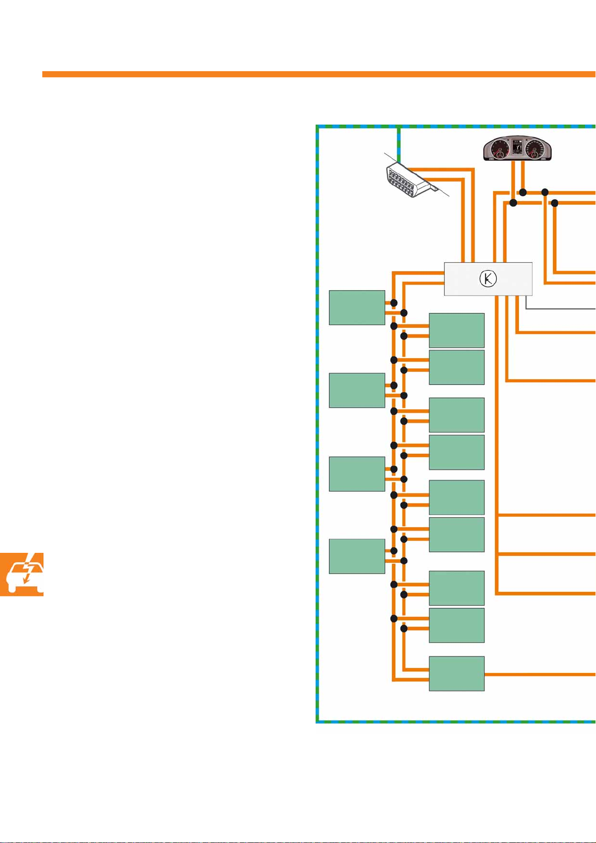
The networking concept . . . . . . . . . . . . . . . . . . . . . . . . . . . . . . . . . . . . . . . . . . . 42
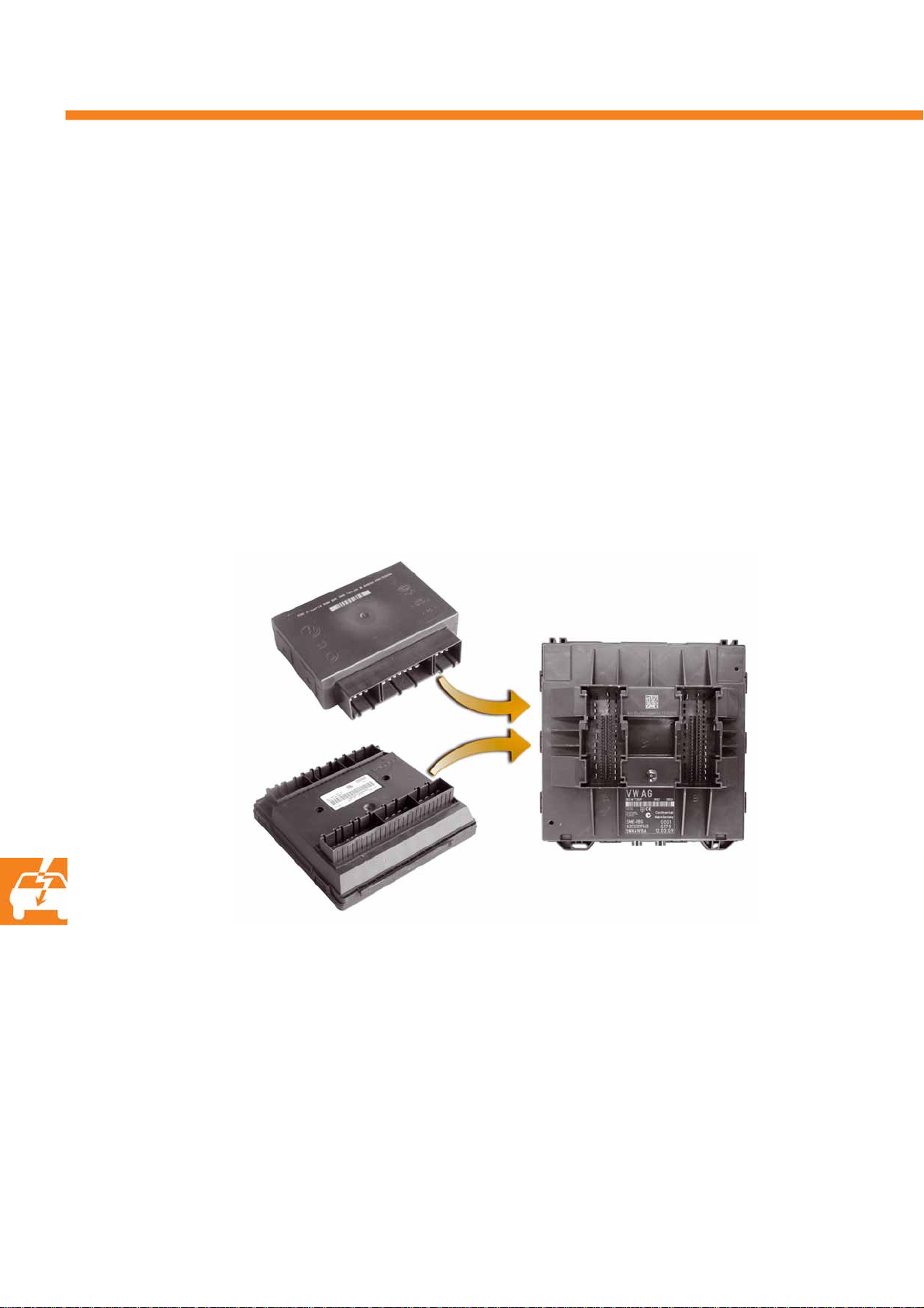
The onboard supply control unit J519 . . . . . . . . . . . . . . . . . . . . . . . . . . . . . . . . 44
The lights. . . . . . . . . . . . . . . . . . . . . . . . . . . . . . . . . . . . . . . . . . . . . . . . . . . . . . . . 46
The lane change assist . . . . . . . . . . . . . . . . . . . . . . . . . . . . . . . . . . . . . . . . . . . . 50
The reversing camera system . . . . . . . . . . . . . . . . . . . . . . . . . . . . . . . . . . . . . . . 51
The dash panel. . . . . . . . . . . . . . . . . . . . . . . . . . . . . . . . . . . . . . . . . . . . . . . . . . . 52
The media device interface box. . . . . . . . . . . . . . . . . . . . . . . . . . . . . . . . . . . . . 53
Radio, phone and navigation. . . . . . . . . . . . . . . . . . . . . . . . . . . . . . . . . . . . . . 54
The radios and radio navigation systems . . . . . . . . . . . . . . . . . . . . . . . . . . . . . 54
The aerial concept . . . . . . . . . . . . . . . . . . . . . . . . . . . . . . . . . . . . . . . . . . . . . . . . 56
The telephone preparation UHV . . . . . . . . . . . . . . . . . . . . . . . . . . . . . . . . . . . . 63
3
Page 4

Introduction
The model family of th e T5 2010
The 2010 model year will see the launch of an extensive remodeling of what is to become the fifth model
generation of the Transporter. Yet again, this vehicle will underline the pioneering role played by Volkswagen
Commercial Vehicles in the segment of people carriers and transporters.
In the 2010 model year, the model range also includes the familiar model variants.
● Platform van
● Panel van
● Window van
● Caravelle
● Multivan
● California
Panel van
Window van
Platform van
(Example: double cab)
Overview of the most important highlights:
● new TDI® engines with common rail injection system,
7-speed dual clutch gearbox, 4MOTION with dual clutch gearbox and
Servotronic,
● Multivan now also with long wheelbase,
● new driver assistance systems, new infotainment programme and new air conditioning controls,
● new "fresh" design in the interior, e.g. new instrument clusters, new fabrics and steering wheels and
new decor for the galley in the California,
● attractive exterior, e.g. with new exterior mirrors, engine cover, headlights, front end, tail lights,
rims and a new range of colours,
● increased operating comfort.
4
Page 5

The new T5 2010 consistently implements the new design language of Volkswagen.
● A clear face - high quality and timeless,
● The horizontal, clean lines make the vehicle
look wide and have great presence on the road.
● Its eyes - open, unique and self-assured.
● The night design of the new tail lights in the
Multivan with Volkswagen Commercial Vehicle's
own signature - its appearance on the road is
immediately recognisable.
Multivan
● Panel van, window van and platform van with
robust and solid, grey grained front and rear
bumpers corresponding to the type of vehicle
● Multivan, Caravelle and California with painted
front and rear bumpers - this underlines the clear,
high-quality character.
The design revisions consistently support the
character properties of the new T5 2010.
Caravelle
S453_122
California
About the model range:
● Predominantly for transporting people - window van, Caravelle, Multivan, California.
● In the other versions, the T5 2010 is chiefly used for transporting loads.
● Within the model range, there are versions with both a short and a long wheelbase and
three different roof heights.
● The maximum possible payloads of the vehicles vary depending on the different operating conditions.
● Some model variants are available with four-wheel drive (4MOTION).
5
Page 6

Introduction
Technical data
Platform van
Platform van
Single cab
S453_004
Platform van
Double cab
S453_104
S453_006S453_005
The pictures only show selected variants and their dimensions/dimension ranges (e.g. with short and
long wheelbase, etc.) - the chassis is not shown here. Please refer to the current sales literature for the
complete set of technical data for the model range.
6
Page 7

Panel van, window van, Caravelle, Multivan, California
Panel van
S453_117
Multivan
With the launch of the T5 2010,
the Multivan will also be
available with a long wheelbase.
S453_029
S453_030
S453_031
S453_145
The pictures only show selected variants and their dimensions/dimension ranges (e.g. short and long
wheelbase, normal roof, medium-high roof and high roof depending on the versions, etc.). Please refer
to the current sales literature for the complete set of technical data for the model range.
7
Page 8
Body
The body
To a large extent, the body has been taken from the previous model.
The front end is new - it has been adapted to the current face of the Volkswagen family and is the same for the
Multivan and commercial vehicles. The engine cover and the exterior mirrors have been improved in terms of
their aerodynamics and reduced wind noise.
Acoustic glazing is also available as an option.
Innovations on the front end in detail:
– An engine cover with new lines and more angular
beading
– The engine cover extends further upwards and
covers the wiper arms in the windscreen area.
– In the lower area, the engine cover extends further
into the radiator grille area.
– The front end has a new assembly mount.
– New exterior mirrors
– New radiator grille
– Modified VW emblem design
–New headlights
S453_131
Front end
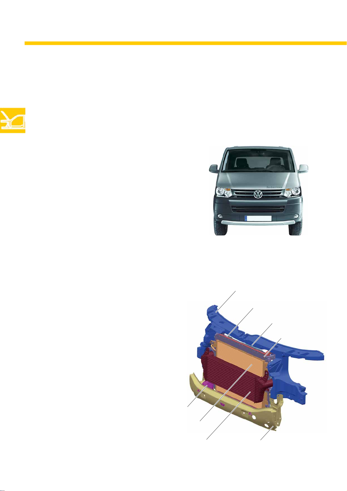
The front end is composed of the following main
components:
– Assembly mount
– Bumper mount
–Bulkhead
–Ventilator
– Radiator
–Condenser
– Intercooler (in the variants for TDI engine and TDI
engine with bi-turbocharger unit)
– Cooler for power steering
Intercooler (for TDI engine)
Bulkhead
Condenser
Assembly mount
Cooler for power steering
Ventilator
Radiator
S453_124
Bumper mount
8
Page 9

Structure of the front end - exploded view
Cooler for power steering
Assembly mount
Ventilator
Intercooler
(for TDI engine)
Bulkhead
Bumper mount
The double fan concept in the previous model will
be discontinued - the T5 2010 now has a single fan
exclusively. The cooling power is adapted to the
equipment level by means of three different fan
powers (450 W, 600 W, 850 W).
Radiator
Condenser
S453_054
The attachments for all components on
the assembly mount have changed.
Please always refer to the information
in the workshop manual.
9
Page 10

Body
Assembl y mo unt
In contrast to the assembly mount in the previous model, the one in the T5 2010 is no longer made from steel but
from a composite material comprising plastic with a steel insert.
The main advantage is the increased weight saving.
In order to guarantee the necessary stability and crash safety of the assembly mount, the upper cross member of
the assembly mount has been fitted with a steel insert. The plastic part is connected to the steel insert by hot
riveting. This involves the steel insert being pushed onto the extruded projections of the plastic part, and then
riveted by compression under the effect of heat.
All other parts of the assembly mount are made entirely of plastic.
Projection of the
plastic part
Upper crossmember
of the assembly mount
Projection of the plastic
part compressed by hot
riveting
Hot riveting
Steel insert of the assembly mount hot-riveted with assembly mount
Plastic part - hot-riveted
with assembly mount
Bumper mount
10
S453_055
Chassis rail
It is essential to comply with the information in the workshop manual with
regard to repair work on the front end - this applies in particular to the
service position as well
Page 11

The tailgate emergency unlocking f unction
All model variants of the T5 2010 with tailgate are equipped with a tailgate emergency unlocking function.
In case of an emergency when the tailgate can no longer be opened, e.g. because:
● The tailgate or the opening mechanism has been damaged due to a crash
● The central locking has failed
● The opening system has failed on an electrically operated tailgate
then it is possible to open the tailgate from the inside.
The emergency unlocking function is installed on the tailgate above the tailgate lock behind a plastic cover.
The cover cap is identified with the "opened tailgate" symbol.
After the cover cap has been removed, the emergency unlocking function can be actuated manually by pressing
the lever for the emergency unlocking function.
Electric motor for
tailgate operation
Cover cap
Tailgate lock
Also refer to the owner's manual for
information about the emergency
unlocking function.
Lever for emergency unlocking
after removal of
the cover cap
S453_108
11
Page 12

Body
Occupa nt pr otec ti o n
As a feature of the Volkswagen safety strategy, the occupant protection system in the T5 2010 has been improved in
the form of a seat belt fastening warning and a modified airbag concept for driver and front passenger protection.
Front passenger airbag
deactivation
In the commercial vehicle variants, the
Front passenger airbag deactivation is another
safety measure. The front passenger airbag can be
deactivated when the passenger door is open, using
the key-operated switch on the right-hand side end
of the dash panel.
belts at each of the outboard positions are
integrated in the body and those for the
middle seat positions are integrated in the
seat.
Module
Head / thorax airbag
Front passenger
Head airbag
Key operated switch to deactivate
front passenger side airbag E224
Module
Side airbag
Front passenger
Front airbag
Driver
Head / thorax airbag
Front passenger
S453_045
Front airbag
Front passenger
12
Module
Front airbag
Driver
Airbag control unit
with crash sensor for
front airbags
Module
Head / thorax airbag
Driver
Page 13

Module
Head airbag
ISOFIX child seat restraint systems are
installed in the Multivan in the individual
seats and, in the commercial vehicles, the
outboard seats in the 1st row of the
passenger compartment.
Head airbag
Belt fastening warning
One feature in the safety concept is the seat belt
fastening warning for the driver's seat which is
installed as standard. An acoustic signal sounds if the
driver's seat belt is not fastened. In addition, a red
warning lamp lights up in the instrument cluster.
Three-point seat belt,
integrated in the seat
Crash sensor, in C-pillar at bottom
Head / thorax airbag
Driver
Three-point seat belt with
rack-type belt tensioner,
attached to body
Crash sensor, in B-pillar at bottom
S453_123
Head / thorax airbag
As a new feature, head / thorax airbags are now
fitted rather than the previously separate side and
head airbags in the passenger compartment. This
means the former two systems for each seat are now
combined into one system.
S453_007
Head / thorax airbag
Driver
S453_121
13
Page 14

Engine
The engine/gearbox combinations
The engine range includes one petrol and four TDI
engines. The power plants are installed transversely.
Engine 5-speed manual
gearbox 02Z
2.0 l/85 kW
petrol engine
AXA
2.0 l/62 kW
TDI engine
CAAA
As far as the gearboxes are concerned, there are 2
manual gearboxes and one automatic.
6-speed manual
gearbox 0A5
DSG automatic
gearbox 0BT
2.0/75 kW
TDI engine
CAAB
2.0 l/103 kW
TDI engine
CAAC, CCHA
2.0 l/132 kW
TDI engine
CFCA
14
Page 15

2.0 l/85 kW petrol engine
The engine has been adapted for use in the T5 2010
with the modified installation position.
Technical features
– Spray nozzles for piston cooling
– Oil pump driven by chain from the crankshaft
– Electrically heated crankcase ventilation
– Secondary air system
S453_017
Technical data
Engine identification
letter
Cubic capacity 1984 cm
Design 4-cylinder inline engine
Valves per cylinder 2
Bore 82.5 mm
Stroke 92.8 mm
Compression ratio 10.3 : 1
Max. power 85 kW at 5200 rpm
Max. torque 170 Nm at 2700 rpm
Engine management BOSCH Motronic ME 7.5
Fuel Super unleaded with ROZ 98
Exhaust
post-treatment
AXA
3
up to 4700 rpm
Pre- and post-cat lambda
probes with continuous
lambda control, exhaust gas
recirculation
Torque and power diagram
To r q u e ( N m )
Engine speed (rpm)
S453_018
Power (kW)
Emissions standard
EU5, EU4, EU3
15
Page 16

Engine
2.0 l/62 kW TDI engine
The diesel engine is a further development
(2nd generation) based on the 2.0 l TDI engine in
the Tiguan or Passat, which has been adapted for the
installation conditions and the specific commercial
vehicle requirements of the T5 2010.
Technical features
– Common rail injection system
– Diesel particulate filter (EU 5)
– Exhaust gas recirculation through the cylinder
head
– Plastic intake manifold
–VTG turbocharger
Technical data
Engine identification
letter
Cubic capacity 1968 cm
Design 4-cylinder in-line engine
Valves per cylinder 4
Bore 81.0 mm
Stroke 95.5 mm
Compression ratio 16.5 : 1
Max. power 62 kW at 3500 rpm
Max. torque 220 Nm at 1250 rpm
CAAA
3
up to 2500 rpm
S453_013
Torque and power diagram
To r q u e ( N m )
Power (kW)
16
Engine management EDC 17CP 20
Fuel Diesel acc. to DIN EN 590
Exhaust turbocharger VTG turbocharger
Exhaust gas
recirculation
Emissions standard EU5 with diesel particulate filter
yes
EU4 without diesel particulate filter
EU3 without diesel particulate filter
Engine speed (rpm)
S453_011
Page 17

2.0 l/75 kW TDI engine
The design of the 75 kW engine is based on the same
engine as the 62 kW engine. The difference is only the
modification to the control unit software used for the
injection system.
Technical features
– Common rail injection system
– Diesel particulate filter (EU 5)
– Exhaust gas recirculation through the cylinder
head
– Plastic intake manifold
–VTG turbocharger
S453_013
Technical data
Engine identification
letter
Cubic capacity 1968 cm
Design 4-cylinder in-line engine
Valves per cylinder 4
Bore 81.0 mm
Stroke 95.5 mm
Compression ratio 16.5 : 1
Max. power 75 kW at 3500 rpm
Max. torque 250 Nm at 1500 rpm
Engine management EDC 17CP 20
Fuel Diesel acc. to DIN EN 590
Turbocharger VTG turbocharger
Exhaust gas
recirculation
CAAB
3
up to 2500 rpm
yes
Torque and power diagram
To r q u e ( N m )
Engine speed (rpm)
S453_012
Power (kW)
Emissions standard EU5 w. diesel particulate filter
EU4 without diesel particulate filter
EU3 without diesel particulate filter
17
Page 18

Engine
2.0 l/103 kW TDI engine
The design of the 2.0 l/103 kW engine is also based
on the same engine as the 62 kW engine.
The difference is only the modification to the control
unit software used for the injection system.
Tech n i c al fe a t u r es
– Common rail injection system
– Diesel particulate filter (EU 5)
– Exhaust gas recirculation through the cylinder
head
– Plastic intake manifold
–VTG turbocharger
Technical data
Engine identification
letter
Cubic capacity 1968 cm
Design 4-cylinder in-line engine
Valves per cylinder 4
Bore 81.0 mm
Stroke 95.5 mm
Compression ratio 16.5 : 1
Max. power 103 kW at 3500 rpm
Max. torque 340 Nm at 1750 rpm
CAAC - Transporter version
CCHA - Multivan, Caravelle
3
up to 2500 rpm
S453_013
Torque and power diagram
To r q u e ( N m )
Power (kW)
18
Engine management EDC 17CP 20
Fuel Diesel acc. to DIN EN 590
Turbocharger VTG turbocharger
Exhaust gas
recirculation
Emissions standard EU5 w. diesel particulate filter
yes
EU4 w/o diesel particulate filter
EU3 without diesel particulate filter
Engine speed (rpm)
S453_014
Page 19

2.0 l/132 kW TDI engine with
bi-turbo unit
The design of the 2.0 l/132 kW engine is based on
the 2.0 l/103 kW engine, but it is equipped with a
bi-turbo unit to provide a power boost.
The control unit software has been adapted
accordingly.
Technical features
(in addition to the 2.0 l/103 kW engine)
– Exhaust manifold module with bi-turbo unit
– Oil filter module with integrated exhaust gas
recirculation cooler
– Cylinder block with additional cooling ducts
– Piston with cooled ring groove
S453_015
Technical data
Engine identification
letter
Cubic capacity 1968 cm
Design 4-cylinder in-line engine
Valves per cylinder 4
Bore 81.0 mm
Stroke 95.5 mm
Compression ratio 16.5 : 1
Max. power 132 kW at 4000 rpm
Max. torque 400 Nm at 1500 rpm
Engine management EDC 17 CP 20
Fuel Diesel acc. to DIN EN 590
Exhaust turbocharger Bi-turbo unit
Exhaust gas
recirculation
CFCA
3
up to 2250 rpm
yes
Torque and power diagram
To r q u e ( N m )
Engine speed (rpm)
S453_016
Power (kW)
Emissions standard EU5 w. diesel particulate filter
EU4 without diesel particulate filter
EU3 without diesel particulate filter
19
Page 20

Power transmission
The gearboxes
Two manual gearboxes, the 02Z and the 0A5
gearbox, and the DSG automatic gearbox 0BT are
used in the T5 2010. They have been designed for
transverse installation in the vehicle.
5-speed manual gearbox 02Z
The 5-speed gearbox is already familiar from the
previous model, and is used with the 4-cylinder
85 kW petrol engine and the 4-cylinder TDI engines
with 62/75 kW. The gearbox can transmit torques up
to a maximum of 250 Nm.
6-speed manual gearbox 0A5
The 6-speed gearbox is also familiar from the
previous model and is used in the 4-cylinder TDI
engines with 103/132 kW. It can transmit torques
up to a maximum of 500 Nm.
The compact design is convenient for transverse
installation, and has been achieved by structuring
it as a 4-shaft gearbox. In the 4-shaft concept, the
pinion shafts are permanently engaged with the
gear on the final drive.
Depending on which gear is engaged, the powerflow
is via the input shaft onto one of the pinion shafts.
The clutch bell housing has been adapted to the
modified installation situation in order for it to be
fitted on the 4-cylinder TDI engine.
S453_026
S453_025
20
Page 21
7-speed dual clutch gearbox 0BT
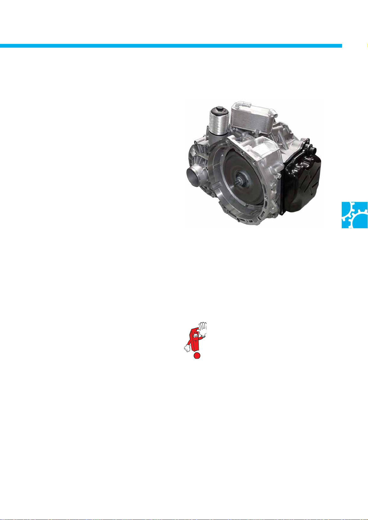
The 7-speed dual clutch gearbox (DSG) 0BT is
being used in the T5 2010 for the first time in the
Volkswagen Group. From March 2010, it will be
possible to combine the DSG with four-wheel drive in
the T5 2010. It can also be used in heavy vehicles with
a gross vehicle weight rating of up to 3.2 t. The 0BT
gearbox is designed for input torques of up to
600 Nm.
The 7-speed DSG will initially only be used
in 103 kW and 132 kW TDI engines. In terms of its
mechanical and control systems, it represents a
significant further development on the previously
familiar dual clutch gearbox.
The 0BT gearbox has been developed entirely within
S453_019
Volkswagen, and is also produced within the
company, to very high manufacturing standards.
All-in-all, it represents a milestone in the gearbox strategy of the Volkswagen Group, which means it contributes to
a further expansion in the technological lead enjoyed by Volkswagen.
Advantages of th e 7-speed DSG at a glance:
● Reductions in fuel consumption and CO2 emissions
● Expansion and further development of expertise
relevant for the competition in dual clutch
gearboxes
● This now permits four-wheel drive with an automatic
For further information about this
gearbox and its selector mechanism,
refer to self-study programme no. 454
"The 7-speed dual clutch gearbox 0BT".
gearbox
● Winning over manual gearbox customers
● With the 7-speed DSG, Volkswagen is securing its
market leadership in the Transporter segment
Tachograph
In vehicles with a tachograph, it is a requirement to have a separate speed signal for recording the vehicle's speed
on the tachograph. The vehicle speed for the tachograph continues to be taken directly from the gearbox. It is now
possible to retrofit a speedometer sender on all gearboxes. There are two different gearbox-specific speedometer
senders for the T5.
21
Page 22
Power transmission
The four-wheel drive
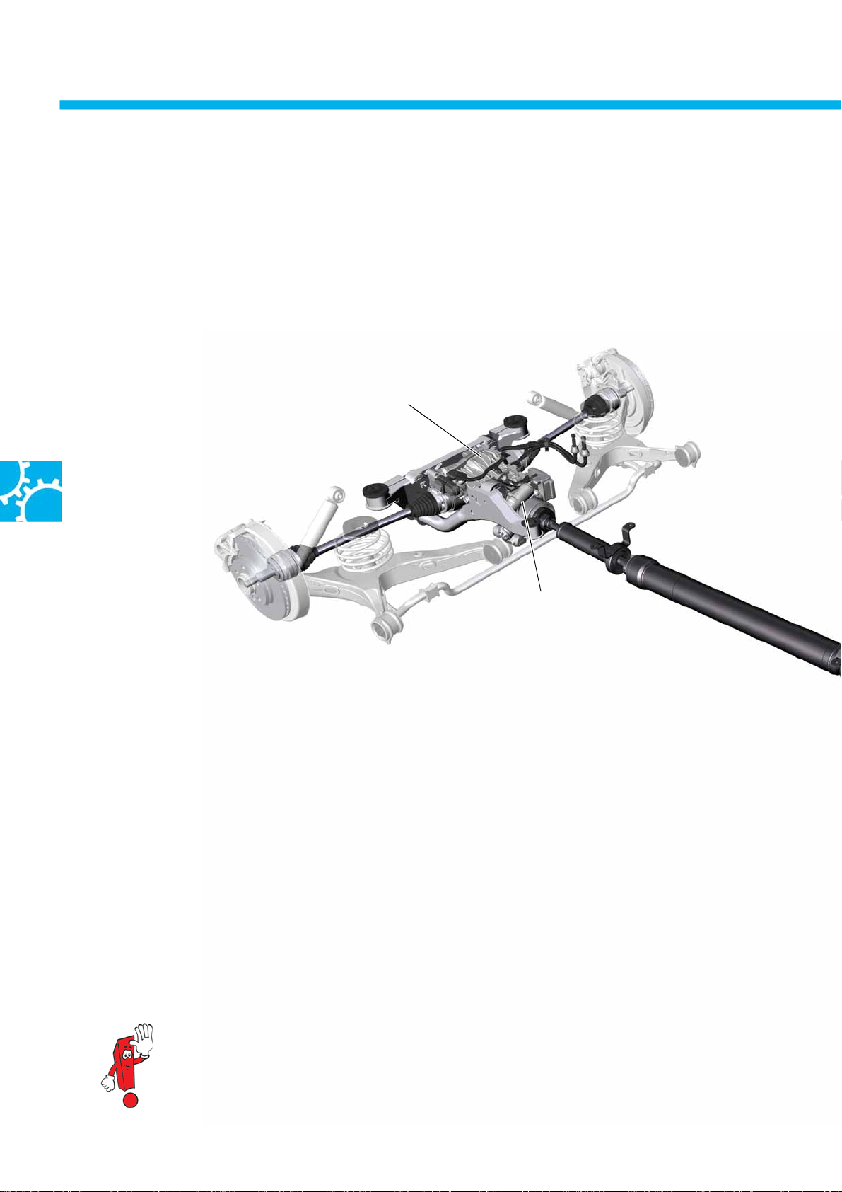
In the T5 2010, four-wheel drive is available in all vehicle variants in conjunction with the 2.0 l 103/132 kW TDI
engines.
It can be used with the 6-speed manual gearbox 0A5 and now, for the first time, also in conjunction with an
automatic gearbox - the 7-speed dual clutch gearbox 0BT.
A Haldex 4th generation coupling is used as the 4WD coupling.
Rear axle box
Haldex coupling
Rear ax le box
The design of the rear axle box has been adapted for installation of the Haldex 4th generation coupling and for
the higher torque requirements in the T5 2010.
As an option, the T5 2010 is available with a mechanical differential lock comprising a dog clutch on the rear axle
box.
22
The picture shows the four-wheel drive system as an example in conjunction with
a dual clutch gearbox.
Page 23
Bevel drive
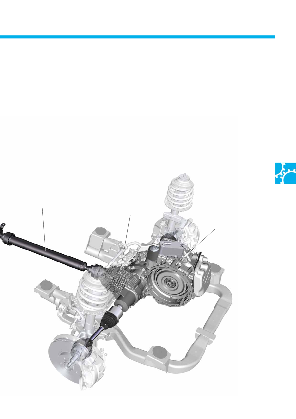
The bevel drive has been adapted for the higher torque requirements in the T5 2010.
Two different bevel drives are used, one of which is adapted for mounting on the manual gearbox and the other for
the dual clutch gearbox.
Propshaft
Bevel drive
Dual clutch gearbox 0BT
S453_043
23
Page 24
Power transmission
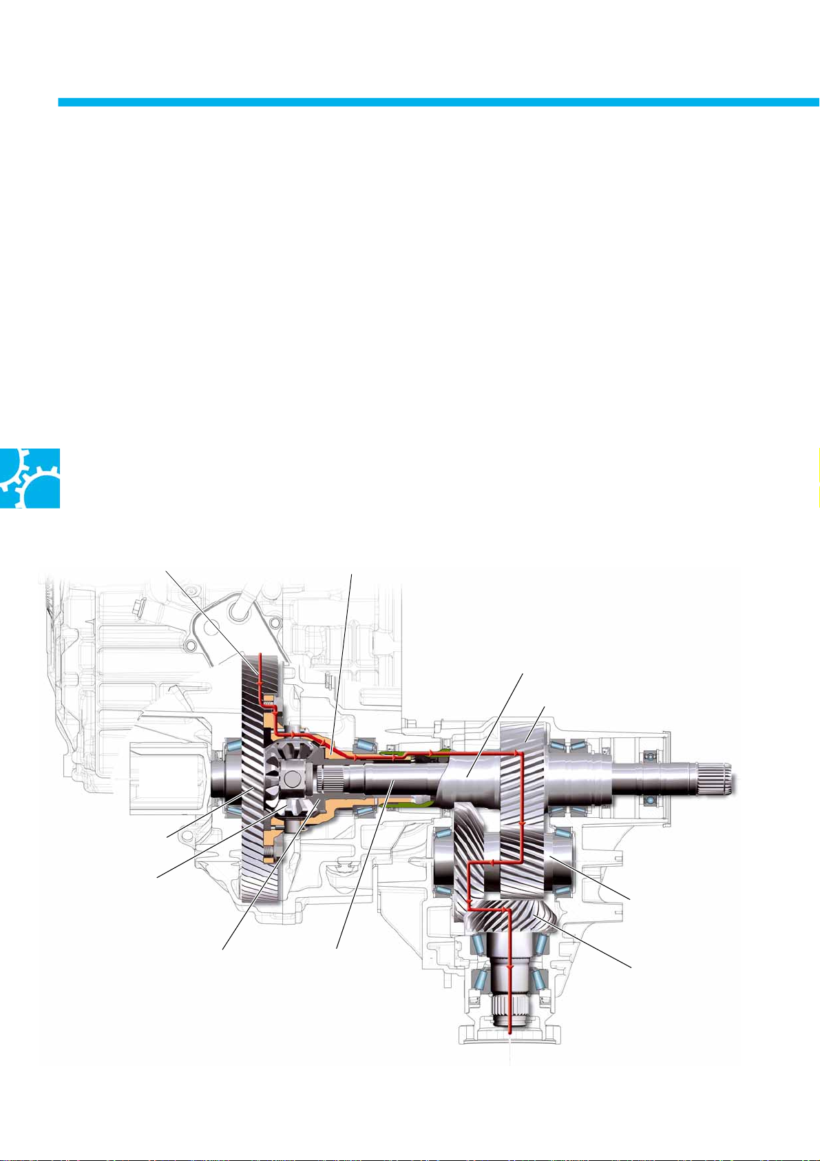
Bevel box
The housing structure, the bearings and the gears of the bevel box have been adapted for the higher torque
requirements in the T5 2010. At the same time, it has been possible to reduce the weight of the bevel box by 6.25 kg
compared to the previous type.
Structure a n d function
The bevel box is driven via a hollow shaft with inner spines. This hollow shaft is a component of the bevel box and
is positively connected to the housing of the differential via its splines. The spur gear on the hollow shaft transmits
the torque onto the intermediate shaft with hypoid gearing and subsequently to the propshaft via the pinion. The
stub shaft for the right front wheel runs inside the hollow shaft. This stub shaft is driven by the shaft bevel gear of
the differential.
Powerflow
Haldex coupling/final drive
to wheel
front left
Final drive
Front axle differential
Differential
housing
The bevel boxes for the manual gearbox and the dual
clutch gearbox differ in the area of the attachment to
the differential.
The picture shows a bevel box combined with a dual
clutch gearbox.
Hollow shaft with inner spines
Hollow shaft spur gear
to wheel
front right
Intermediate shaft with
hypoid and spur gearing
24
Shaft bevel gear
Stub shaft for
right front wheel
to
rear final drive
Pinion with hypoid gearing
S453_027
Page 25
Rear final driv e
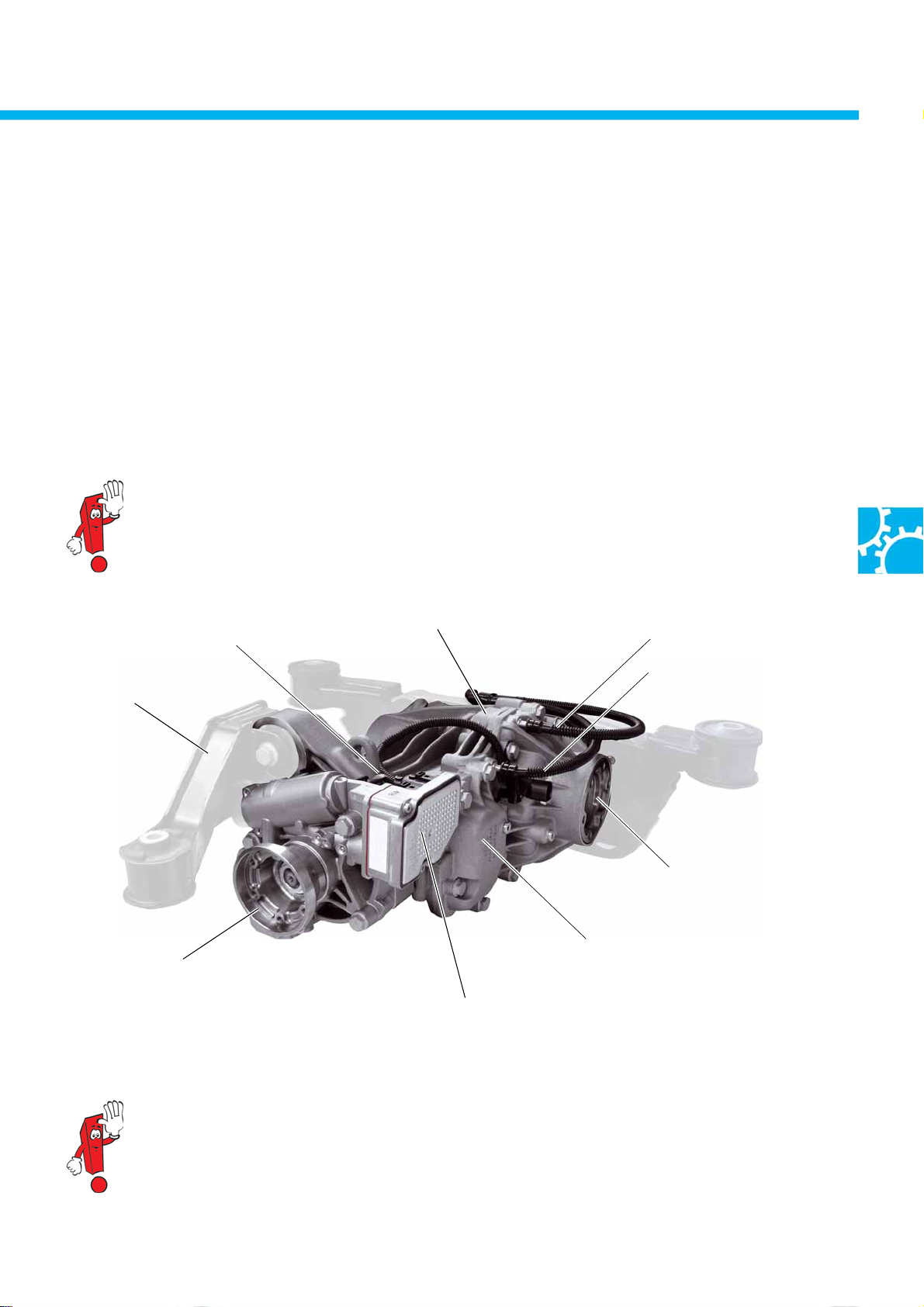
The design of the rear final drive has been adapted for installation of the Haldex 4th generation coupling and for
the higher torque requirements in the T5 2010, as far as the housing and the bearings are concerned.
The reservoir tank for the Haldex oil is an integral component of the final drive housing. This means it is protected
against mechanical damage from the outside.
The Haldex 4th generation coupling is similar in design to the Haldex coupling in the Caddy and Tiguan.
Optionally, the rear axle drive is available with a mechanical differential lock.
More information about the Haldex 4th generation coupling is available in self-study programme
no. 414 "4MOTION with generation IV 4WD coupling".
Mounting frame
Drive flange
Haldex coupling
Rear axle box
Four-wheel drive control unit J492
Ve nt il at io n
Rear axle box
Ve nt il at io n
Haldex coupling
S453_132
Output flange
left
Reservoir
Haldex oil (metal)
When service work is carried out on the rear axle box, refer to the information in ELSA (Electronic
Service Information System) or in the technical product information documents. This applies to the oil fills
in particular. Never mix up oils for the rear axle box and for the Haldex coupling with one another!
If oils are mixed up or there is no oil fill, there will be massive damage to the final drive and/or the
Haldex coupling.
25
Page 26
Power transmission
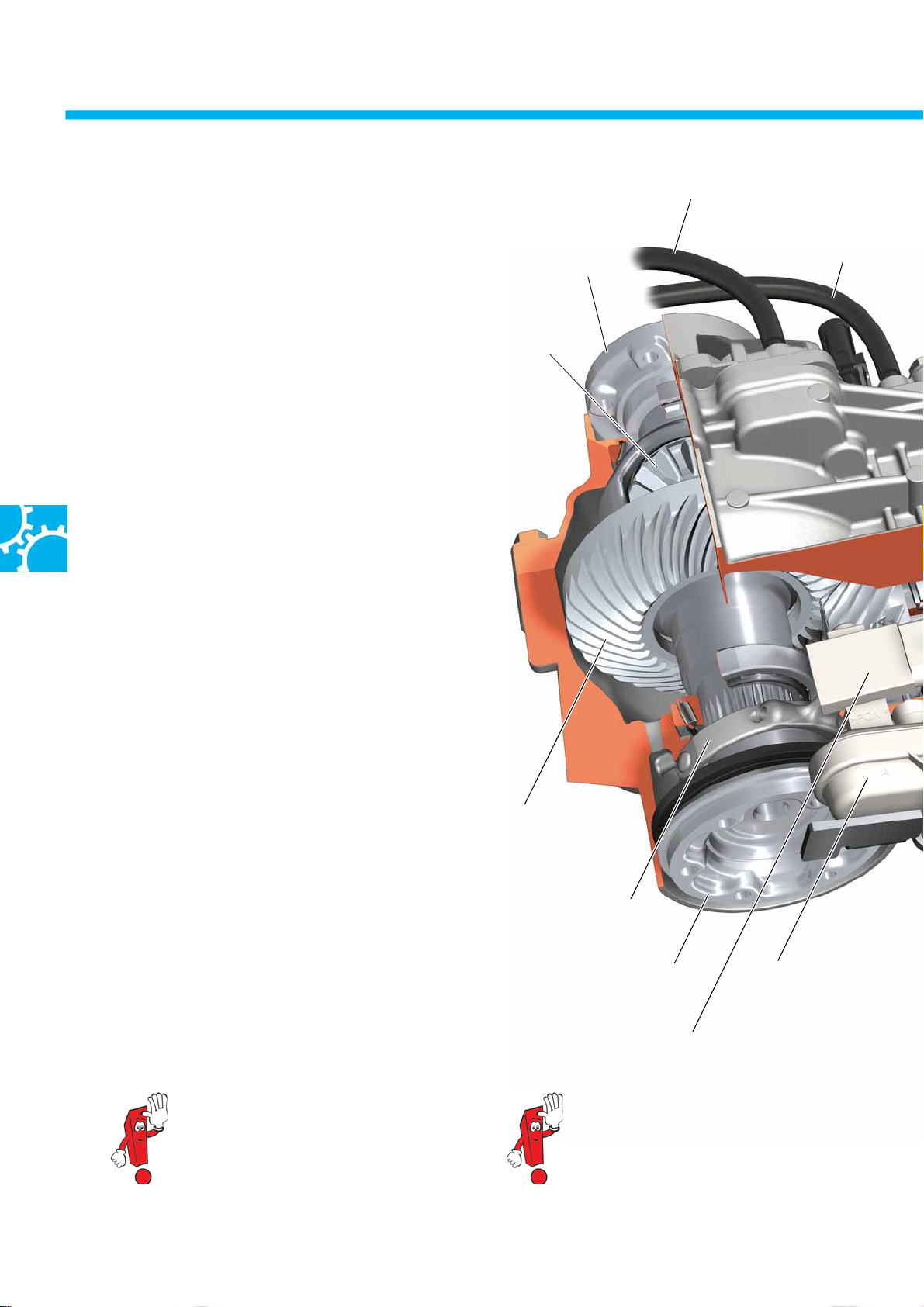
Cutaway view – rear axle box
The rear final drive of the four-wheel drive T5 2010
consists of the Haldex 4th generation coupling, the
final drive and the optionally available differential
lock. The transmission ratio is 2.466.
The Haldex coupling is integrated into the final drive
and can be renewed separately.
The oil supply to the Haldex coupling and the final
drive comes from two different oil circuits. Two oils
adapted to the particular requirements are used for
lubrication and cooling.
The two oil circuits are sealed off from one another
internally by a double oil seal.
This separates both the oil circuits from one another.
There is a spacer between the two halves of the
double oil seal, in order to guarantee that there will
be a narrow gap. The gap is connected to the
atmosphere by means of a breather hole in order to
equalise the pressure.
Drive
to left wheel
Differential
Ven til at io n
Rear axle box
Ventilation
Haldex coupling
In the event of a leak of the pinion, it is possible for
leaking Haldex or final drive oil to reach the outside
via the breather hole.
The double oil seal prevents any mixing between the
two oils.
Mixing would impair the lubrication properties of
both oils, and could result in malfunctions in the final
drive or in the Haldex coupling.
For more information about the
differential lock, refer to self-study
programme no. 333 "4MOTION with
Haldex coupling".
Crown wheel with
hypoid gearing
Operating lever for
dog clutch
Reed contact switches 1-3 for
differential lock F360- F362
For more information about the Haldex
4th generation coupling, refer to self-study
programme no. 414 "4MOTION with
Haldex 4th generation coupling".
Drive to
right wheel
Pressure unit for
differential lock
26
Page 27
Pinion
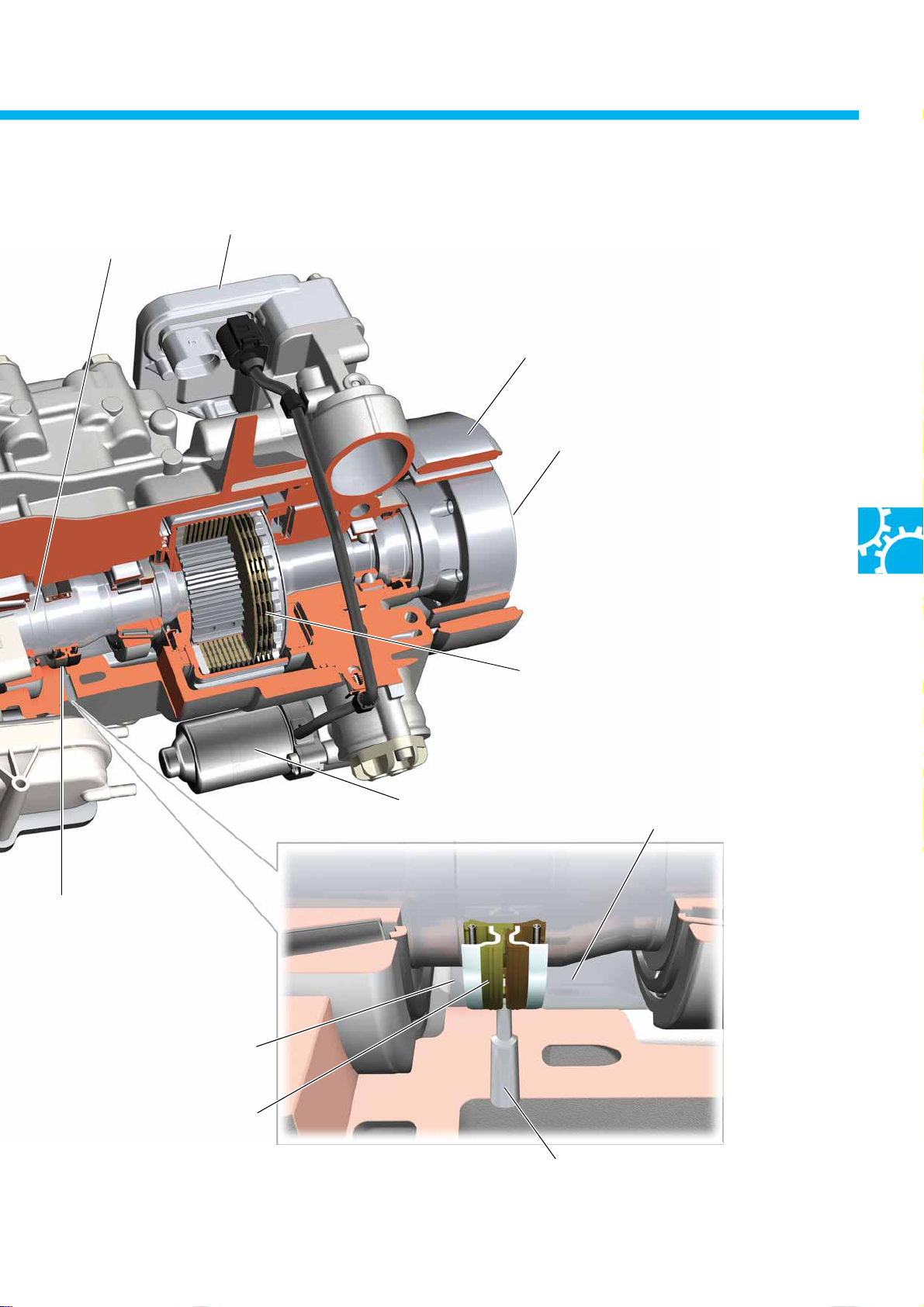
Four-wheel drive control unit J492
Torsional vibration damper
Drive from
propshaft
S453_130
Double oil seal
Oil space
final drive oil
Double oil seal
Pump for
Haldex coupling V181
Multi-disc pack of the
Haldex coupling
Oil space
Haldex oil
Breather hole
27
Page 28
Running gear
Overview of the running gear
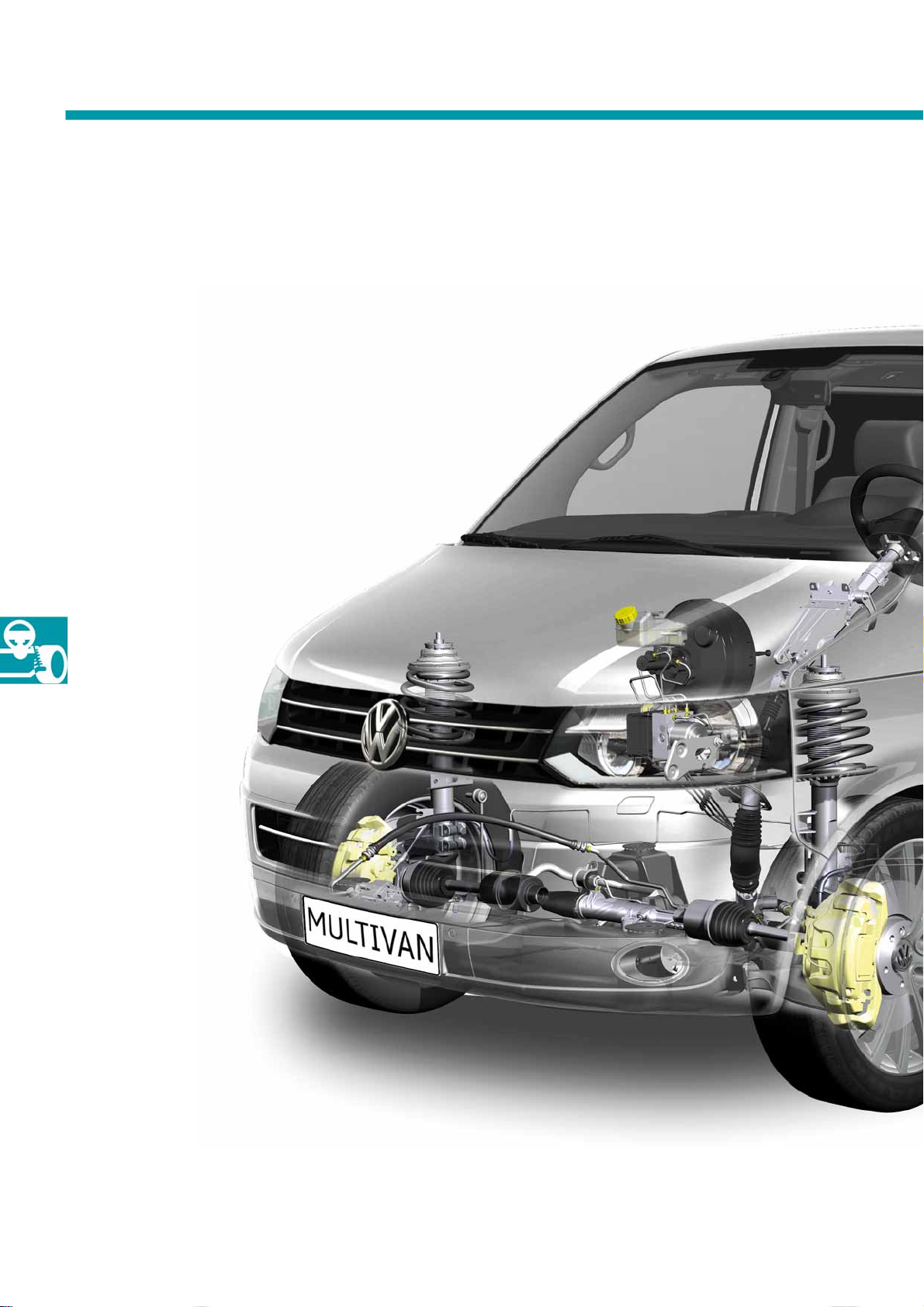
The basic structure of the running gear in the T5 2010 corresponds to that in the previous model.
Some important components of the running gear have undergone further development. This means it satisfies the
demands of driving even more effectively.
● Revised ESP generation with extended
range of functions
● Brake light switch and sender for clutch
position in revised version
28
● Adjustable steering booster pump
● The front axle design is adopted from
the Transporter 2004
● Servotronic steering with speed-
dependent control
Page 29
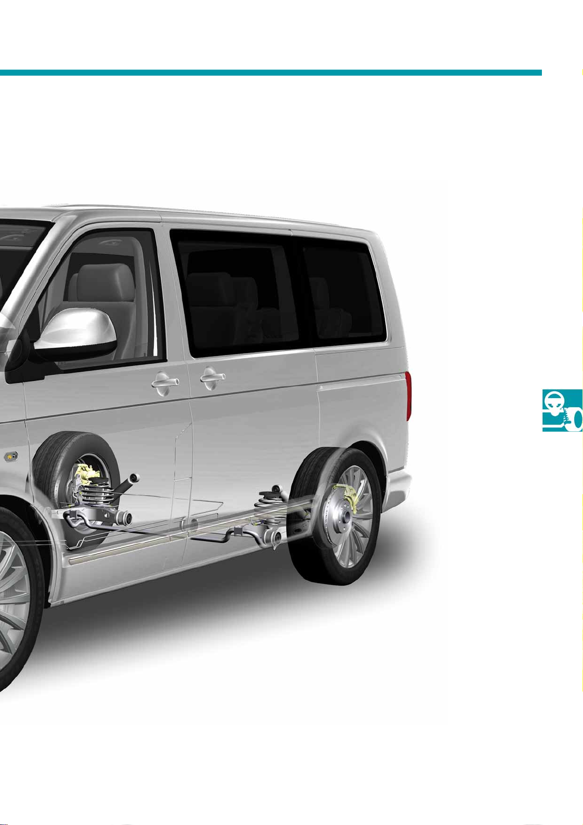
● Four-wheel drive now also with the new
7-speed dual clutch gearbox 0BT
The picture corresponds to front-wheel drive.
● New 17-inch dual piston brake
on the front axle
S453_076
● The rear axle design is adopted from
the Transporter 2004
29
Page 30
Running gear
The brake system
ESP system
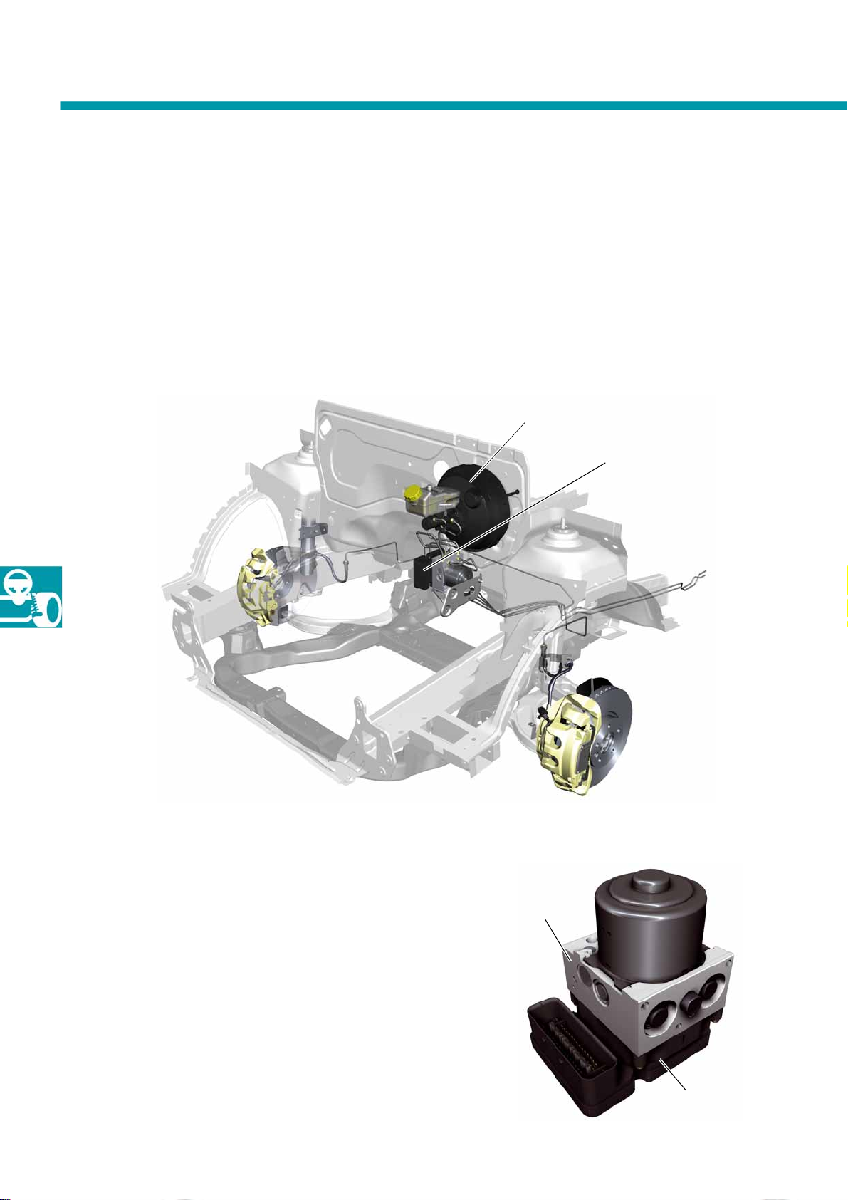
From model year 2010 onwards, all T5 vehicles will receive the latest generation of ESP (electronic stabilisation
programme). This is a further contribution towards the continuous process of meeting the safety targets set by
Volkswagen Commercial Vehicles.
The ESP system is not available at present in back-to-back cabs (T5 cabs) intended for subsequent completion,
e.g. as a mobile home, vehicle transporter or for manufacturing special vehicles.
Brake booster
ESP control unit
(control unit for ABS J104)
30
The ESP system MK 25 A-XT from Continental Teves is installed.
ESP (electronic stability programme) also combines
the familiar functions:
● ABS (Anti-lock Brake System)
● EDS (electronic differential lock)
● TCS (Traction Control System)
● MSR (engine drag torque control)
● Hill hold assist
S453_085
Hydraulic unit
S453_034
Control unit
Page 31

The system has the following new functions in addition
to those already named:
Function Functional description
ARP
(active rollover protection)
Maximum brake support
Ready alert brake (prefill)
Fading brake support
Hydraulic brake assistant
ARP minimises the risk of rolling over when cornering. If the transverse acceleration
threshold value set for the individual vehicle is exceeded during cornering, the engine
torque is reduced and the front wheel on the outside of the curve is braked. This reduces
the rollover torque. Due to the large payload of the T5 2010, the vehicle load is generally
included in the ARP control calculations.
The control unit uses the longitudinal acceleration sender to register the current
acceleration and uses the ratio between this and the engine torque, including the overall
ratio, to calculate 3 different load conditions (unladen, half-laden and fully laden). Then,
according to the load condition, the ESP control unit controls the optimum application
point for ESP.
Increased braking power (especially when vehicles are laden) during ABS control. When
the front axle starts ABS-controlled braking, the brake pressure at the rear axle is
increased until this also enters ABS-controlled braking.
If the foot is withdrawn rapidly from the accelerator pedal then it can be expected that
emergency braking will follow.
Therefore, in such situations, the brake pads are moved up into contact with the brake
disc so that brake intervention can be more rapid, thereby reducing the braking distance.
If fading is detected (reduction in brake effectiveness when brakes are hot) then
the brake pressure is increased using the ABS pump, thereby improving the braking
effect.
The pneumatic brake assistant is replaced by a hydraulic brake assistant in the T5 2010.
The brake assistant is activated when the driver presses the brake pedal quickly, but not
powerfully enough. The system interprets this as panic braking, so the brake pressure is
increased by the ABS pump until ABS control starts.
Rain brake support
Trailer stabilisation
Tyre pressure monitor TPM
As soon as the windscreen wipers are switched on, the brake pads are brought into
contact briefly with the brake disc at regularly intervals, thereby removing any film of
water from the brake discs that may be present due to rain/splash water. This improves
the responsiveness of the brake system in wet weather.
When driving with a trailer, trailer stability assist keeps the vehicle and the
trailer on track. According to the requirements, individual wheels of the towing vehicle
are braked or deceleration is initiated by reducing the engine torque. This means the
vehicle/trailer combination is stabilised in case there is a risk of it becoming unstable.
At present, this function is only possible if the trailer tow hitch is ordered as initial
equipment.
The ESP control unit incorporates an indirectly measuring tyre pressure monitor for
detecting a loss in tyre inflation pressure by evaluating the rolling circumferences of the
wheels. If a tyre loses pressure, this is detected within a few minutes of driving by means
of specific evaluation of the wheel speeds.
31
Page 32
Running gear
Front brake
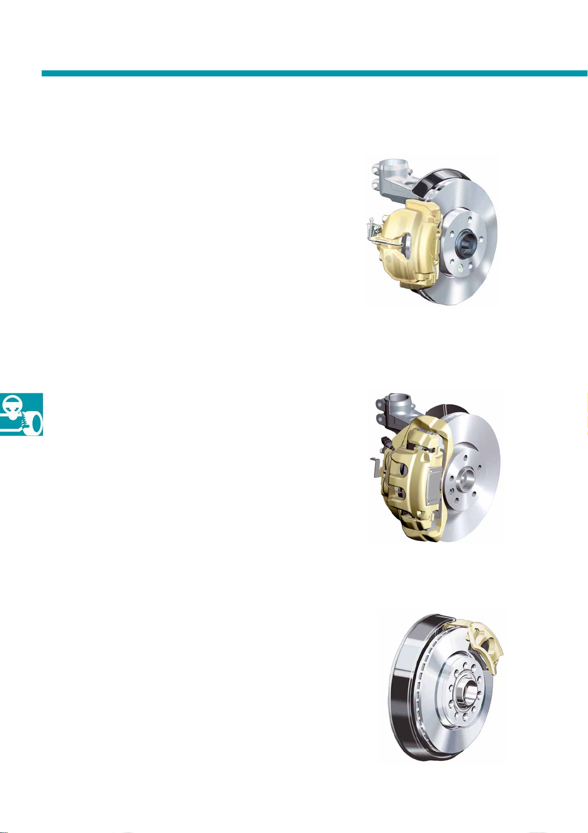
On its front axle, the T5 2010 has a 16-inch brake
system.
The ventilated brake discs have the
dimension Ø 308 x 29.5 mm.
All T5 2010 vehicles with 132 kW engine or a gross
vehicle weight rating of more than 3000 kg are
equipped with new, revised 17-inch brakes on the
front axle as standard.
The 17-inch brake is optional for all other engines.
The larger brake disc combined with the increase
in pad contact area, improved pad pressure by a
double piston calliper and more rigid housing thanks
to the frame calliper principle mean that the braking
effect is significantly improved, thereby increasing the
performance of vehicle models with a 132 kW engine.
16-inch front brake
S453_082
17-inch dual piston front brake
The ventilated brake discs have the
dimension Ø 340 x 32.5 mm.
Rear brake
The rear axle of the T5 2010 is fitted with 16-inch
brakes.
The ventilated brake discs have the
dimension Ø 294 x 22 mm.
S453_083
16-inch rear brake
S453_084
32
Page 33
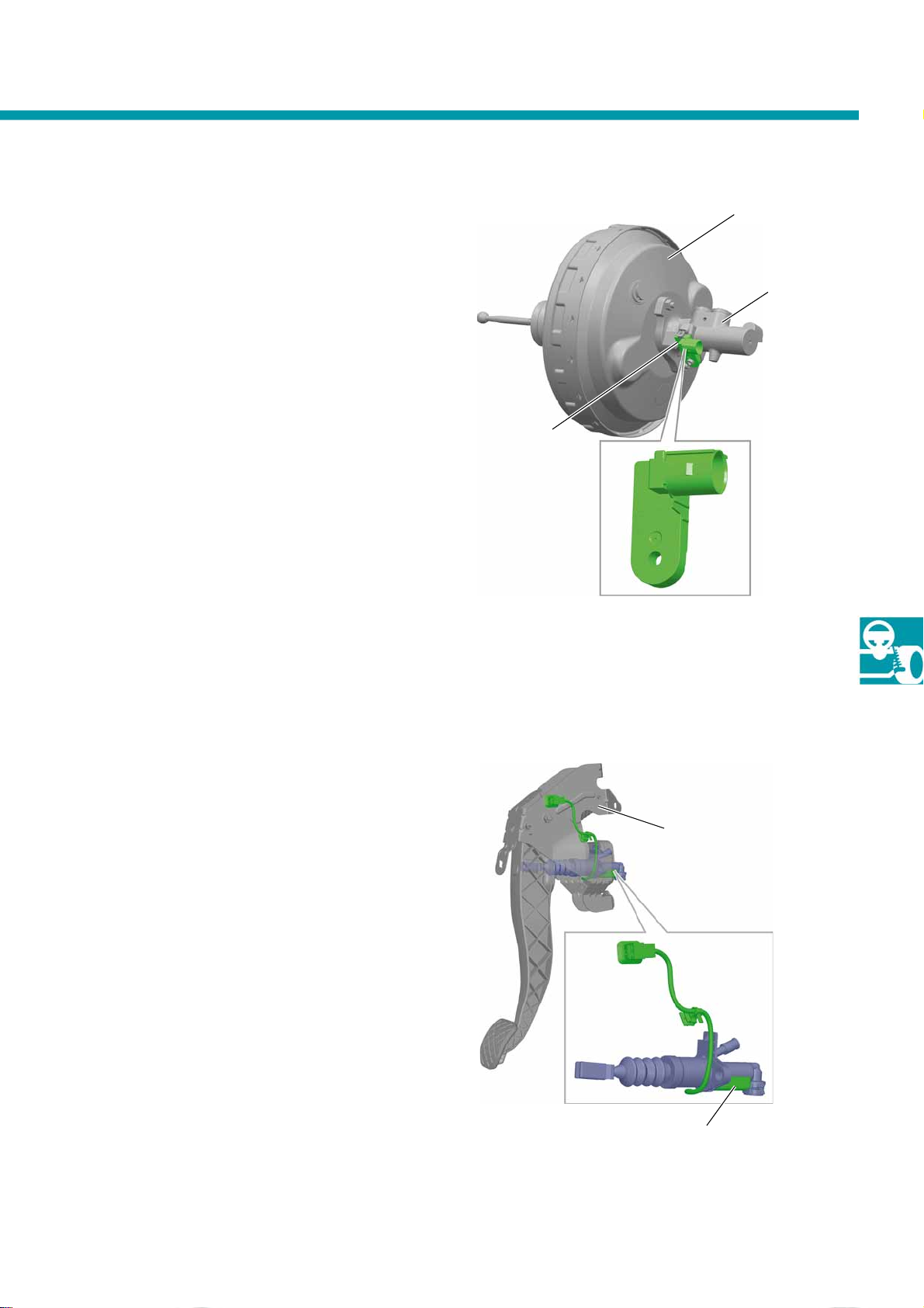
Brake lig ht switch on main brake
cylinder
Brake booster
The mechanical switches on the pedal mechanism
have been discontinued in all T5 2010 vehicles, and
replaced by a brake light switch on the tandem main
brake cylinder of the brake booster.
This brake light switch is one component that
comprises two Hall sensors (to provide redundant
backup).
The signals from both Hall sensors are sent to the
engine control unit.
The brake light switch can be renewed individually.
Ta nd e m
main brake cylinder
Brake light switch
S453_142
Clutch position sender
Exclusively in the 132 kW engine version, a sender
positioned on the clutch master cylinder is used for
establishing the clutch position.
Two Hall sensors installed in the clutch position sender
register when the clutch is actuated and also when the
clutch pedal has been fully depressed.
The clutch position sender cannot be replaced
individually.
Clutch pedal
S453_143
Clutch position sender
33
Page 34
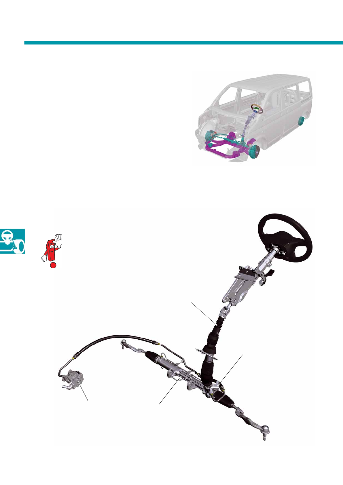
Running gear
The steering
All T5 2010 vehicles are equipped with hydraulic
power steering.
Servotronic is available as standard for all Multivan
Highline vehicles and is an option for all other
T5 2010 models.
It is a feature of Servotronic that the steering support
is reduced as the vehicle speed increases. This
increases driving safety.
S453_072
More details about Servotronic is
available in self-study programme no. 277
"The Phaeton - running gear".
Steering booster pump
Steering box
Steering column
Power steering hydraulic
pressure valve N315
34
S453_081
Page 35
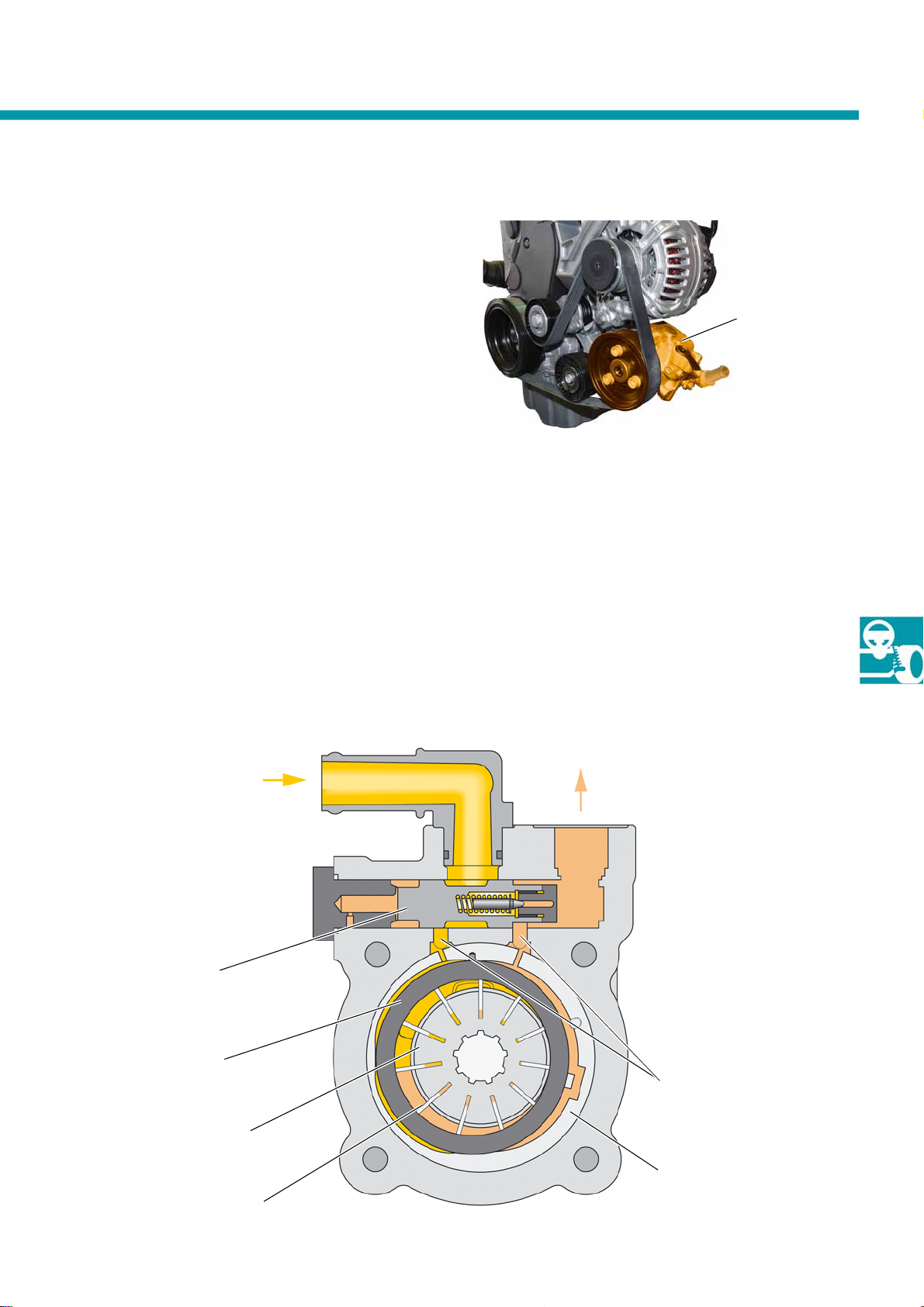
Adjustab le ste erin g booster pump
The adjustable steering booster pump is mounted on
the engine below the alternator, and is driven by the
belt drive of the engine. It is used in all T5 2010
vehicles with a diesel engine.
Structure and function
Steering booster pump
S453_114
● The adjustable steering booster pump operates
according to the functional principle of an
adjustable radial piston pump.
● The pump has a cam disc, allowing the vanes to
be adjusted.
● The delivery rate can be varied by the different
positions of the vanes.
Input
from
servo oil tank
● The adjustment enables the pressure of the
hydraulic pump to be adapted to the engine
speed, thereby ensuring that the delivery pressure
of the pump remains approximately constant.
● Advantage: This avoids any unnecessarily high
power consumption by the hydraulic pump. As a
result, fuel consumption is reduced.
Pressurised oil to
steering box
(output)
Control piston
Cam disc
Rotor
Vanes
(11 piece s)
Stroke adjustment
activation on both sides
Outer ring
S453_077
35
Page 36
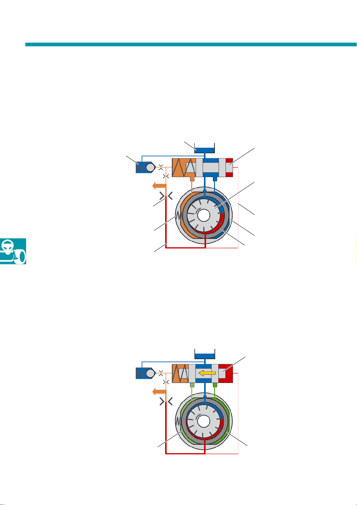
Running gear
Function
At idling speed …
the cam ring of the pump is pressed against the outer ring by spring force and the internal pressure conditions. This
produces the greatest possible delivery volumes on the suction and pressure sides. The delivery volume increases
as the rotation speed increases, in proportion to the rotation speed.
Oil tank
Control piston
Pressure relief valve
to steering box
Throttle
Compression spring
Pressure hose
S453_078
Rotor
Control line
Outer ring
Cam ring
As the rotation speed rises …
the pressure in the pump also increases. The pump pressure acts on one side of the control piston, and moves this to
the left against the spring force as the pressure increases. In a defined medium rotation speed range, the ducts to
the chambers between the outer ring and cam ring (left and right chambers) are closed by the control piston. This
equalises the pressure between the two chambers. The cam ring is held in a defined central position, the delivery
volume remains approximately constant.
36
Left chamber
Control piston
Right chamber
S453_080
Page 37
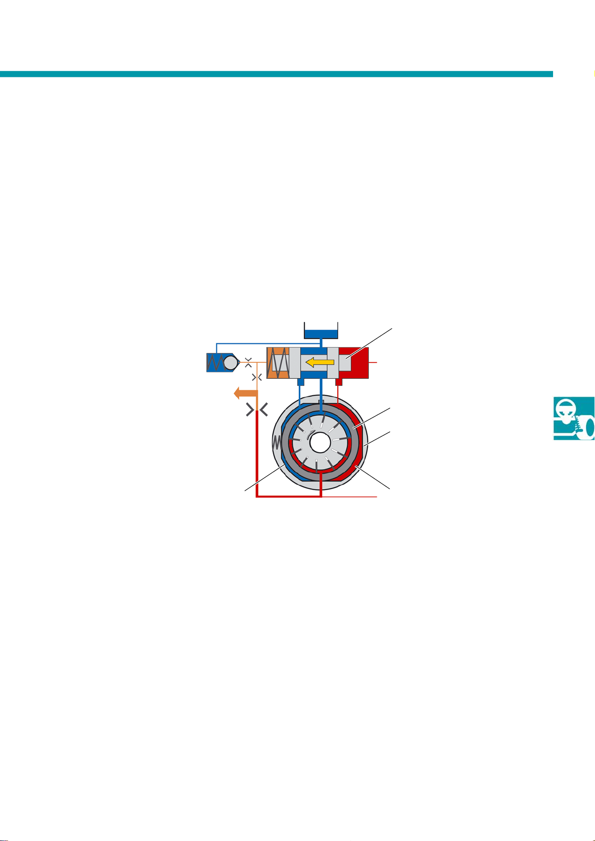
As the rotation speed increases further …
The delivery volume and pressure increase if the rotation speed continues to rise. The control piston is pushed
further to the left against the spring force, and therefore the duct to the left chamber is connected to the suction
line. The opposite, right chamber has pump pressure applied to it. The cam ring is pushed to the left against the
spring force - the eccentricity between the rotor and the cam ring is reduced. The delivery volume is reduced,
thereby preventing "overproduction" of pressurised oil. The associated reduction in power consumption by the
pump means that energy consumption is reduced significantly.
Control piston
Cam ring
Outer ring
S453_079
Right chamberLeft chamber
37
Page 38
Heating and air conditioning
The climate control
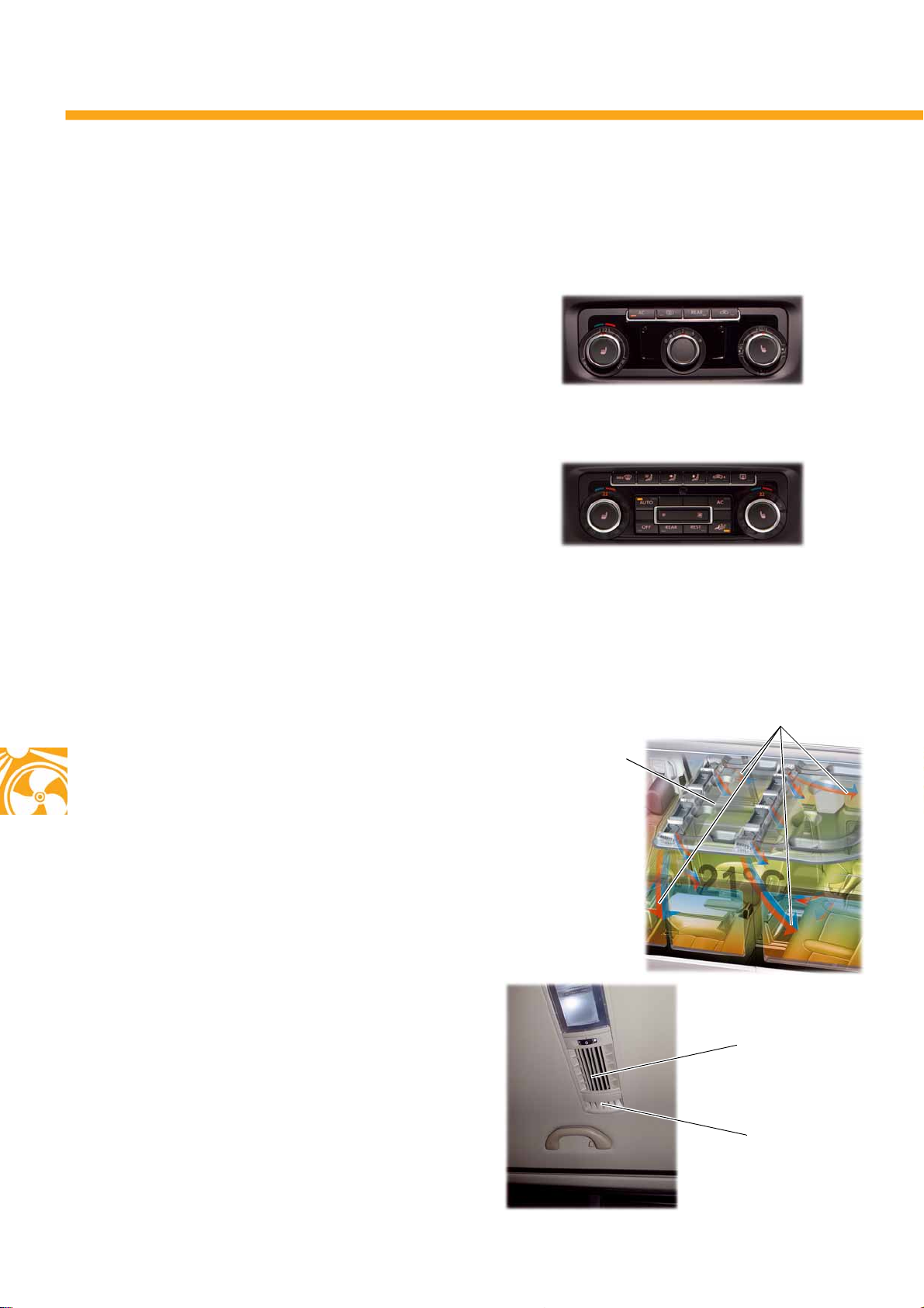
The T5 2010 not only uses the manual heating and ventilation system but also the semiautomatic Climatic air
conditioning system and the fully automatic Climatronic air conditioning system.
Climatic
The Climatic replaces the manual air conditioning
system familiar from the predecessor. The desired
temperature is set on the electronic temperature dial,
and this value is reached by adjustment of the
temperature flap depending on the temperature
conditions in the interior. The settings for the blower
speed and air distribution are made manually on the
relevant dials.
Climatic control unit
S453_128
Climatronic
The Climatronic enables all functions to be controlled
fully automatically. Two different automatic modes are
provided for the fresh air blower control. AUTO High
mode is an automatic mode with optimum air
quantities in order to counteract any possibility of
fogging, and to achieve the desired temperature in
the passenger compartment as soon as possible.
AUTO Low mode is a mode with small air quantities.
Acoustic comfort takes precedence. The temperature
control is less abrupt, the fresh air blower speed is
lower than in AUTO High mode.
Side nozzles in comfo rt headlining
The T5 2010 with comfort headlining not only has
nozzles for air-conditioning the compartment air, but
also special side nozzles located further out from the
normal nozzles. These side nozzles are used for
blowing hot air over the side windows.
These nozzles make an effective contribution to
keeping the side windows from fogging, or else make
it possible to clear the side windows within a very
short time.
S453_129
Climatronic control unit
Air from side nozzles
Headlining with air
guidance system
S453_148
Nozzles in headlining - for airconditioning the compartment air
38
Side nozzles
S453_149
Page 39
The auxiliary heaters
The T5 2010 can be equipped with the following auxiliary heaters:
Auxiliary heating
● Airtronic D3/B3 Plus auxiliary air heater
(manufacturer: Eberspächer)
● Thermo Top C auxiliary water heater
(manufacturer: Webasto)
Supplementary heater
● Thermo Top Z auxiliary water heater
(manufacturer: Webasto)
Operating and display unit
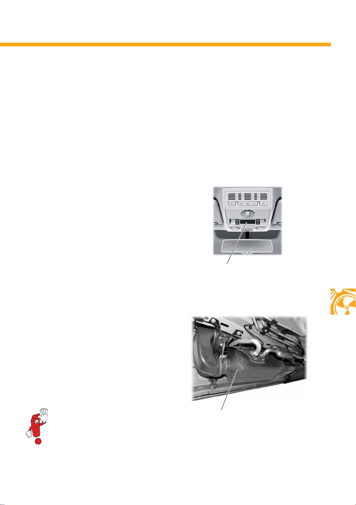
The auxiliary heaters are operated by the operating
and display unit for the auxiliary heater E407 in the
roof - in the California, the auxiliary heater is
operated using the operating and display unit for
camping equipment E153.
S453_126
Operating and display unit
for auxiliary heater E407
Airtronic auxiliary air heater
D3/B3 Pl us
The Airtronic D3/B3 Plus auxiliary heater is fitted in the
T5 2010 in the same installation location as the
replaced Air Top 3500 of the T5 2004.
The advantages of the Airtronic D3/B3 Plus are:
– More compact dimensions
–Lower weight
– Optimised and more precise control
of the heating power levels
The basic structure and function of the
Airtronic D3/B3 Plus corresponds to those of
the Airtronic D2/D4S. For more information,
refer to self-study programme no. 416
"Auxiliary heaters - part 2 Volkswagen
Commercial Vehicles".
S453_125
Auxiliary heater
Airtronic D3/B3 Plus
39
Page 40
Electrics
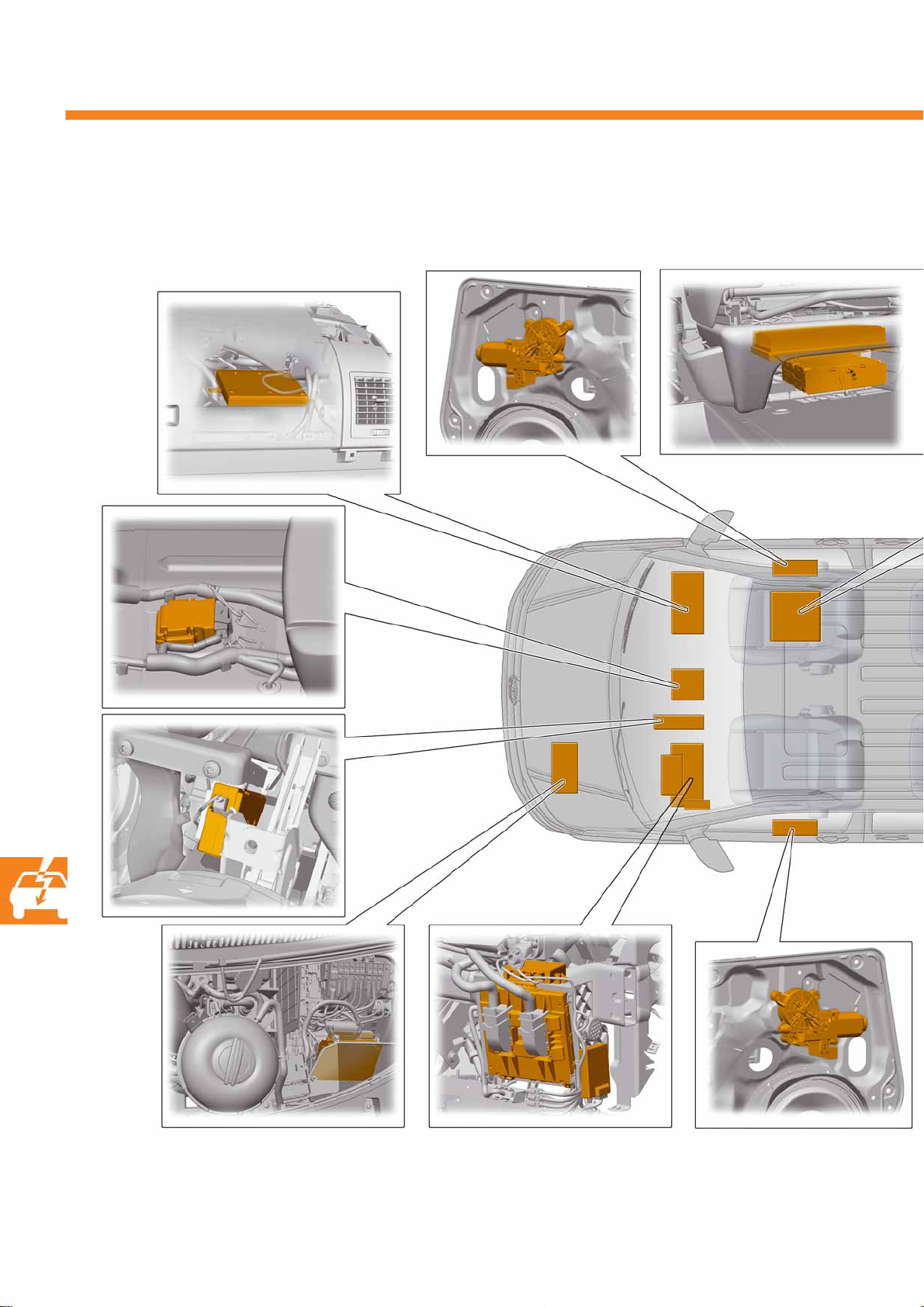
The insta llation locat ion s of the control units
UHV control unit
Control unit for right
door
Airbag control
unit
Amplifier and
TV tuner
40
Engine control unit
MDI control
unit
Control unit for
parking aid
Onboard supply
control unit
Control unit for left
door
Remote control
receiver for
auxiliary heating
Page 41
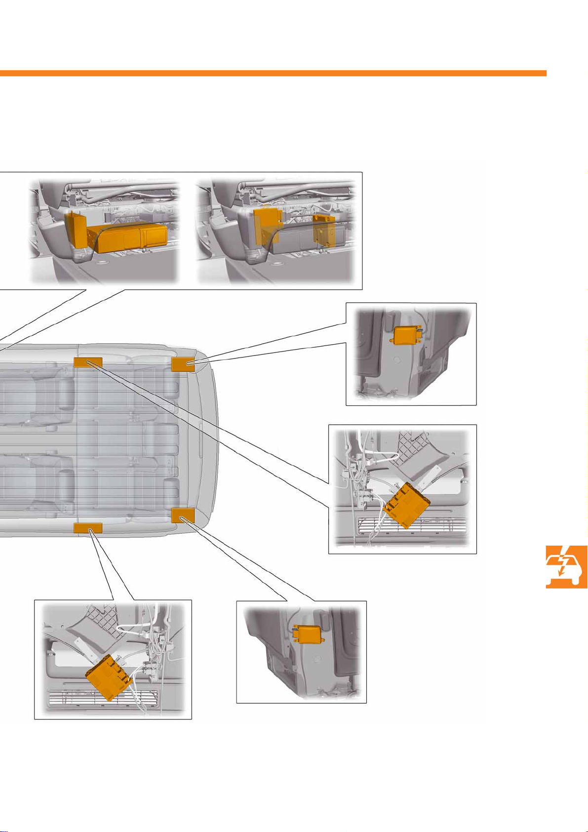
Control unit for
voice amplification
and CD changer
Control unit for
trailer detection
Control unit for
reversing camera
Control unit for
lane change assist right
Left sliding door control unit
Control unit for
right sliding door
453_089
Control unit for
lane change assist left
41
Page 42
Electrics
The networking concept
What the abbreviations mean
E265 Rear climate control unit
E313 Selector lever
G24 Tachograph
G85 Steering angle sender
G303 Interior monitor send and receive module 1
G305 Interior monitor send and receive module 2
G384 Vehicle inclination sender
G397 Rain and light sensor
G419 ESP sensor unit
H12 Anti-theft alarm horn
J104 ABS control unit
J162 Water heater control unit
J234 Airbag control unit
J255 Climatronic control unit
J285 Control unit in dash panel insert
J345 Trailer detector control unit
J362 Immobiliser control unit
J364 Auxiliary air heater control unit
J386 Driver door control unit
J387 Front passenger door control unit
J412 Mobile telephone operating electronics control
unit
J446 Parking aid control unit
J492 Four-wheel drive control unit
J503 Control unit with display for radio and
navigation
J519 Onboard supply control unit
J527 Steering column electronics control unit in
steering wheel
J533 Data bus diagnostic interface
J558 Left sliding door control unit
J623 Engine control unit
J656 Voice amplification control unit
J702 Roof display unit
J772 Reversing camera system control unit
J731 Right sliding door control unit
J743 Mechatronic unit for dual clutch gearbox
J769 Lane change assist control unit
J770 Lane change assist control unit 2
J788 Isolator relay for CAN data bus drive
R12 Amplifier
R78 TV tuner
R215 Interface for external multimedia devices
T16 Diagnostic connection
R78
R215
J162
J345
T16
J285
a
J503
J412
J558
J731
J702
R12
J772
J656
J255
J362
J519J533
d
c
b
42
Page 43
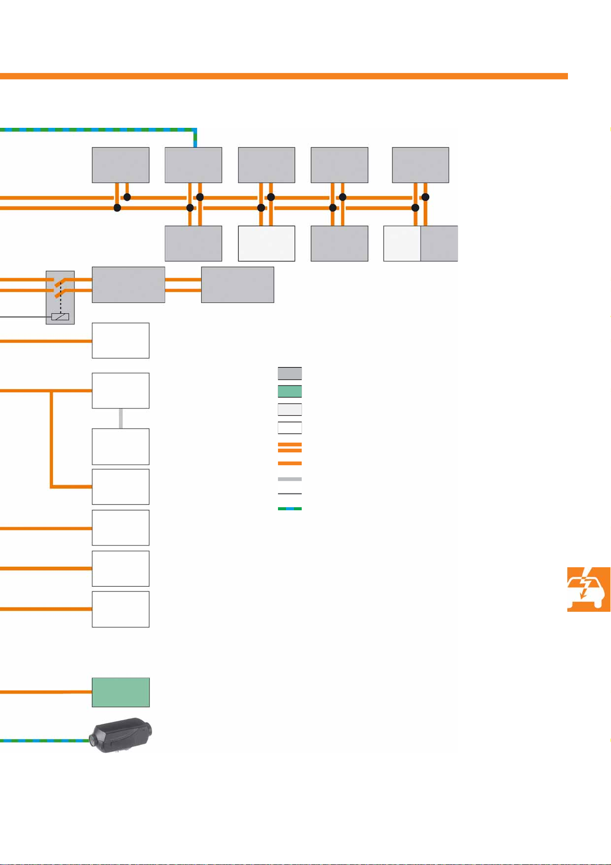
only for 2.0 l petrol engine
J788
J492
J769
(Master)
H12
G303
G384
G305
G397
J446
J770
(Slave)
J743J623
G85
E313
G24
CAN data bus driveline
CAN data bus comfort/infotainment
CAN data bus sensor
LIN data bus
CAN data bus line
LIN data bus line
Data line
Control line
K-line
J234
J104 G419
J527
J386
J387
E265
a CAN data bus diagnosis
b LIN data bus door
S453_024
c LIN data bus roof
d LIN data bus local interconnect network
J364
43
Page 44
Electrics
The onboard supply control unit J519
The new onboard supply control unit J519 in the T5 2010 has had various functions added to it. In contrast to the
onboard supply control unit in the previous model, it now also handles the functions of the convenience system
central control unit J393.
The onboard supply control unit J519 is connected to the onboard supply system via two 73-pin connectors.
Depending on the variant of the onboard supply control unit J519 (which varies in accordance with the vehicle
equipment), it takes over the control of a wide variety of bulbs by means of integrated semiconductor switches.
The particular bulb function is switched via one pin each in this case (e.g. all the turn signals on one side).
Bulb monitoring has been implemented for the bulbs switched by the onboard supply control unit.
Configuration
previous model
Configuration
model year 2010
Convenience system
central control unit J393
Onboard supply control
unit J519
Depending on the control unit variant, the J519 controls at least the following external lighting functions
and monitors them:
● Turn s i gna l
● Side light/tail light
● Brake light
New onboard supply control unit J519
S453_057
44
There are also bulbs that are switched via relays, e.g. main beam and headlight flash.
The aerial for radio remote control is integrated in the new onboard supply control unit. It is not configured as a
wire aerial but rather as a printed circuit board aerial.
Page 45
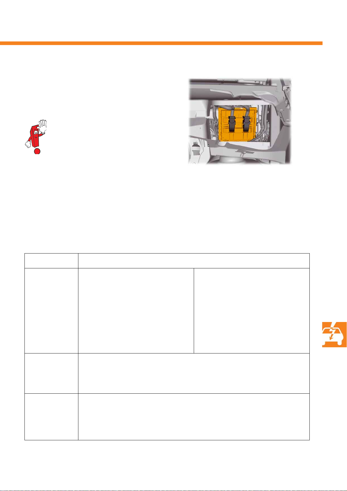
Installation location
The onboard supply control unit is fitted in a bracket
on the left under the dash panel.
The picture shows a view from the engine
compartment through a cut-out opening
in the bulkhead.
S453_069
Function
The range of functions depends on the equipment. More complex equipment extends the range of functions
compared to the more straightforward equipment, as shown by the functions listed in the table.
The functions listed in the table include those functions that are used in the T5 2010 with its current equipment - the
full range of possible functions of the onboard supply control unit is more extensive.
Control unit version Range of functions of onboard supply control unit
Medium ++ - Load management
- Control of electric fuel pump
- Terminal control/terminal registration
- Front and rear wiper control
- Horn control
- Battery isolation relay control
- Heated rear window control
- Heated exterior mirror control
- Headlight washer system control
- Interior light control
- Brake light and turn signal/hazard warning
light control
High+ - Shift lock and starter interlock
- Reversing light control (DQ500 only)
- Cruise control system
- Fog light/static turning light control
- LIN data bus anti-theft alarm (alarm horn)
Lights - Enable/read in main beam, light flash
- Automatic running light, coming home, leaving home
- Low beam, number plate light, daytime running light control
- Rear fog light control
- Reversing light control
- Additional variant for radio remote control (315 MHz)
- Side light and parking light control
- Seat heater and tilting/sliding sunroof enable
- Central locking
- Anti-theft alarm
- Radio remote control (433 MHz)
- Diagnostic interface for data bus
- CAN diagnosis, driveline and convenience
- LIN data bus door (driver and front passenger
door, multifunction steering wheel)
- LIN data bus roof (rain/light sensor, interior
monitor/tilt sensor)
45
Page 46
Electrics
The lights
Headlights
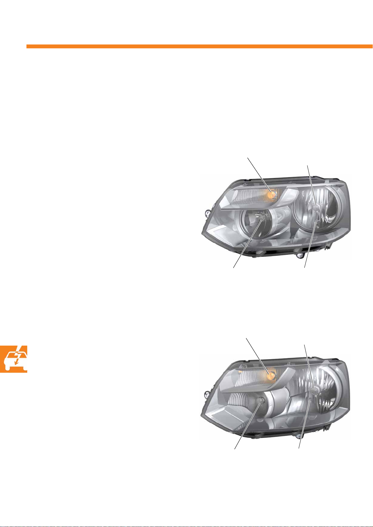
The external design and also the interior structure of the chambers of the headlight unit have been adapted to
Volkswagen's new style. As in the previous model, it has a clear glass structure and is installed in the two variants
with H4 and H7 headlight module.
Headlight module H7
The T5 2010 is equipped with an H7 headlight model
according to the model and equipment.
If there are no daytime running lights then only the
55 W coiled filament of the H15 bulb is used.
Tur n signal
PY, 21 W
Main beam/
daytime running lights
H15, 55/15 W
Tur n s ign a l
PY, 21 W
Dipped beam
H7, 55 W
S453_023
Side light
W, 5 W
Low beam/main beam
H4, 60/55 W
46
Headlight module H4
The T5 2010 is equipped with an H4 headlight model
according to the model and equipment.
If there are no daytime running lights then the bulb
for the daytime running lights is still fitted, but it
cannot be used.
Daytime running lights
P, 21 W
S453_022
Side light
W, 5 W
Page 47
Tail lights
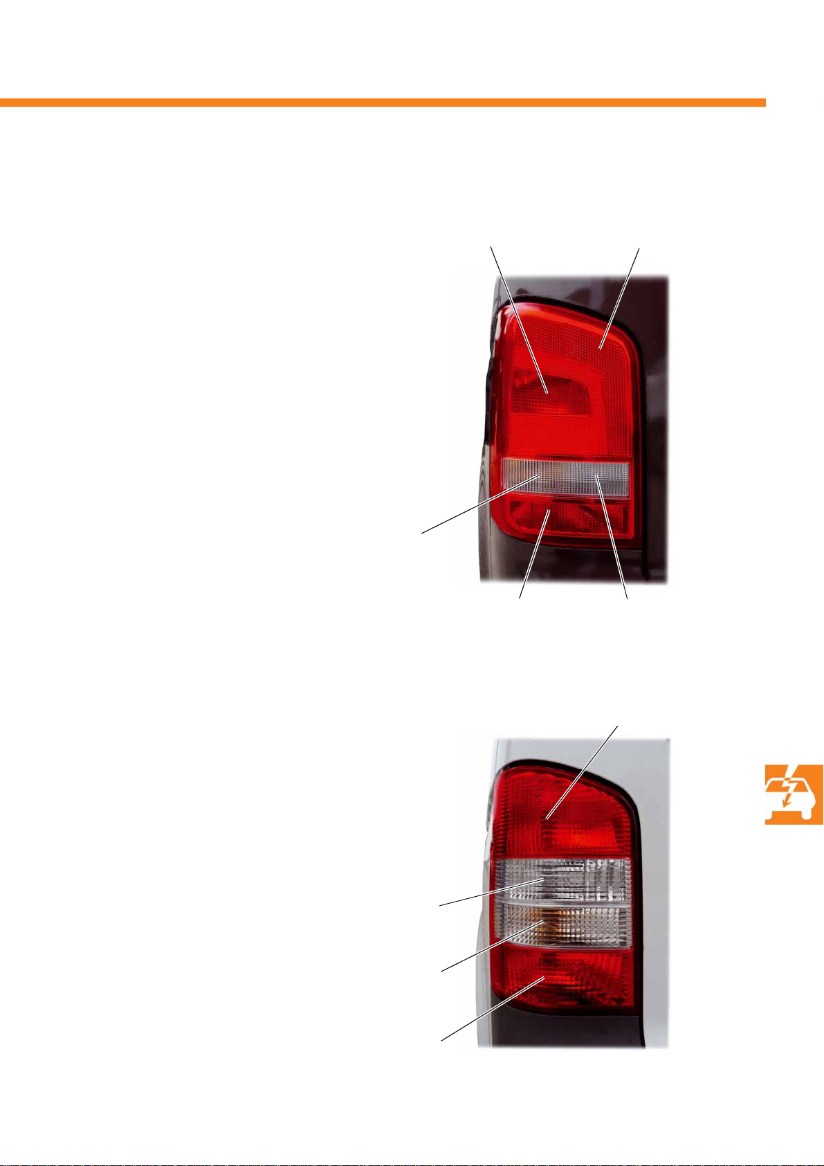
The T5 2010 has two different tail lights.
In conjunction with the H7 headlight module, a new
tail light is used which differs from the tail light in the
previous model by its more striking design, its internal
structure and the resulting distribution of the
illuminated surfaces.
Tur n signal
PY 21 W
Brake and tail lights
P 21/5 W
Tail light
R 10 W
S453_135
All other model variants of the T5 2010 retain the tail
light familiar from the Multivan 2004, which is
installed together with the H4 headlight module.
Reversing light
P 21 W
Turn s i g n al
PY 21 W
Rear fog light
P 21 W
Reversing light
P 21 W
Brake light
P 21 W
Rear fog light and tail light
P 21/4 W - driver side only
S453_136
47
Page 48
Electrics
!
Emergency brake display
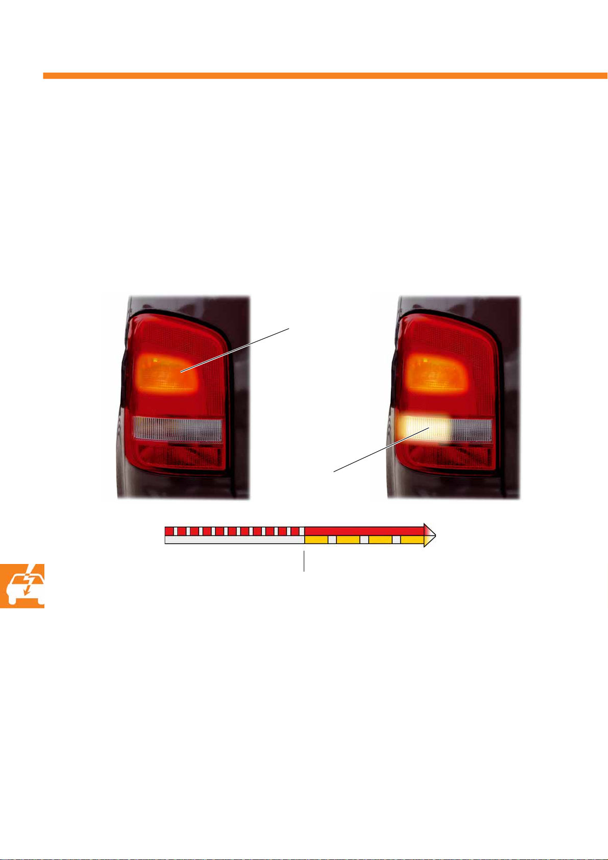
All model variants of the T5 2010 now feature the new "emergency brake display" function.
The ABS control unit J104 detects an emergency braking situation based on the stored threshold values for
deceleration and/or the ABS intervention time. It sets an emergency braking threshold if the speed is still faster than
60 km/h at this time. The onboard supply control unit controls the function of the emergency brake display in
response.
S453_096
Emergency braking flash
Brake light
flashing
Hazard warning
lights flashing
Emergency warning flash
S453_098
48
10 km/h
The emergency brake display is given in two stages.
● Emergency braking flash - When the vehicle is braked in a dangerous situation, the brake lights flash with high
frequency as a warning to the traffic behind
● Emergency warning flash - If the speed drops below 10 km/h in this emergency braking situation then the
brake lights stop flashing and reverts to a steady light for as long as the brake pedal is still being pressed.
The hazard warning lights are switched on.
The hazard warning lights are switched off automatically when the vehicle accelerates again and its speed
exceeds 10 km/h
The hazard warning lights can also be switched off manually using the button on the dash panel
Page 49
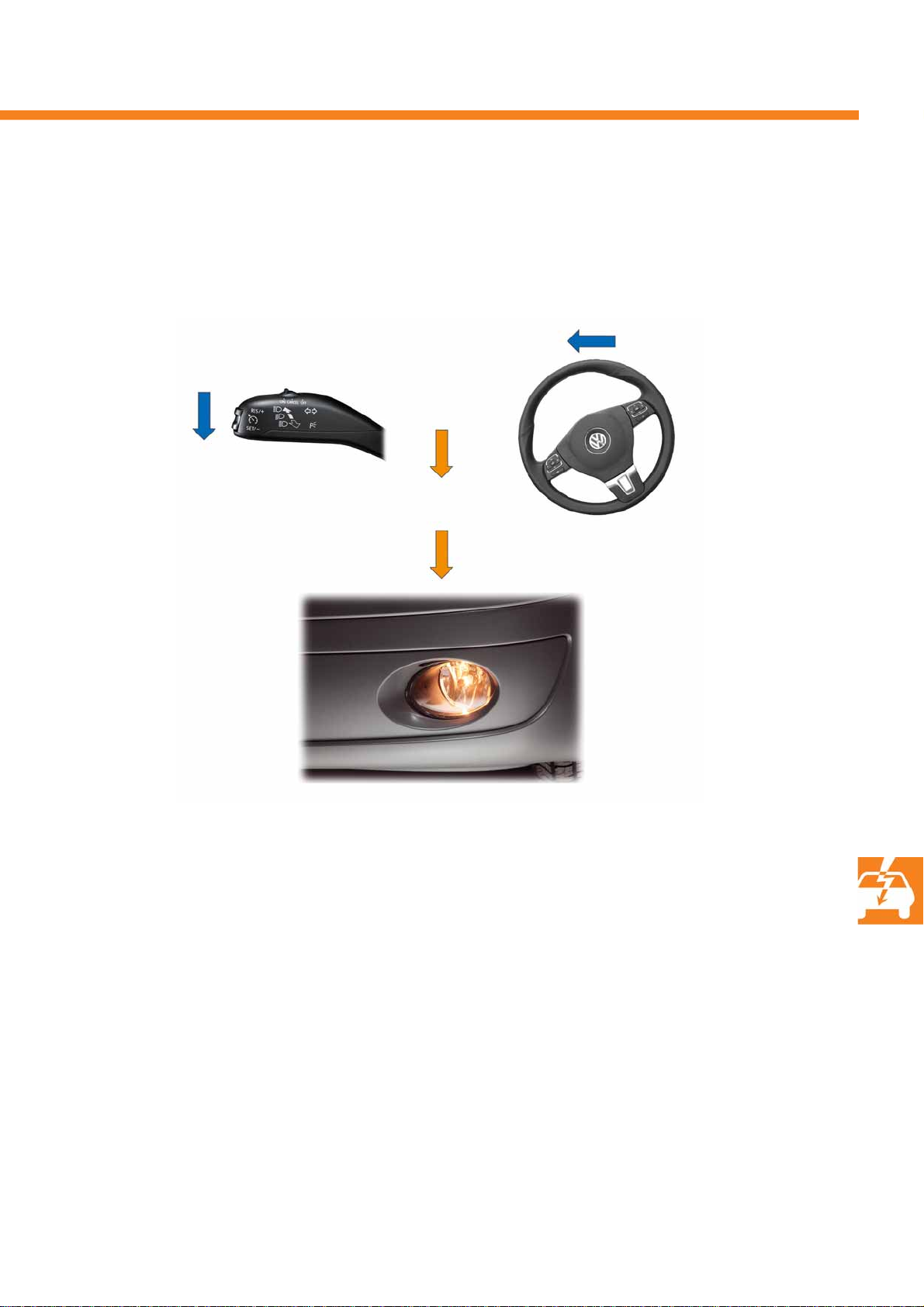
Fog light - static turning light
If the T5 2010 is equipped with fog lights then these are also used for the function of the static turning light.
Indicator stalk
or
< 40 km/h
Steering wheel
S453_099
Fog lights
The static turning light is switched on by the onboard supply control unit J519 in accordance with the vehicle speed,
the steering wheel angle and the turning request.
The turn indicator signal has a greater priority than the steering angle in this case. For example, if the onboard
supply control unit receives the information "turn indicator = left" and "steering wheel angle = right" then the
direction of the indicators applies.
At speeds up to 40 km/h, the side of the road on the inside of the bend is illuminated by the fog light when the
vehicle is turning. The light is switched on and off with a dimming function.
49
Page 50
Electrics
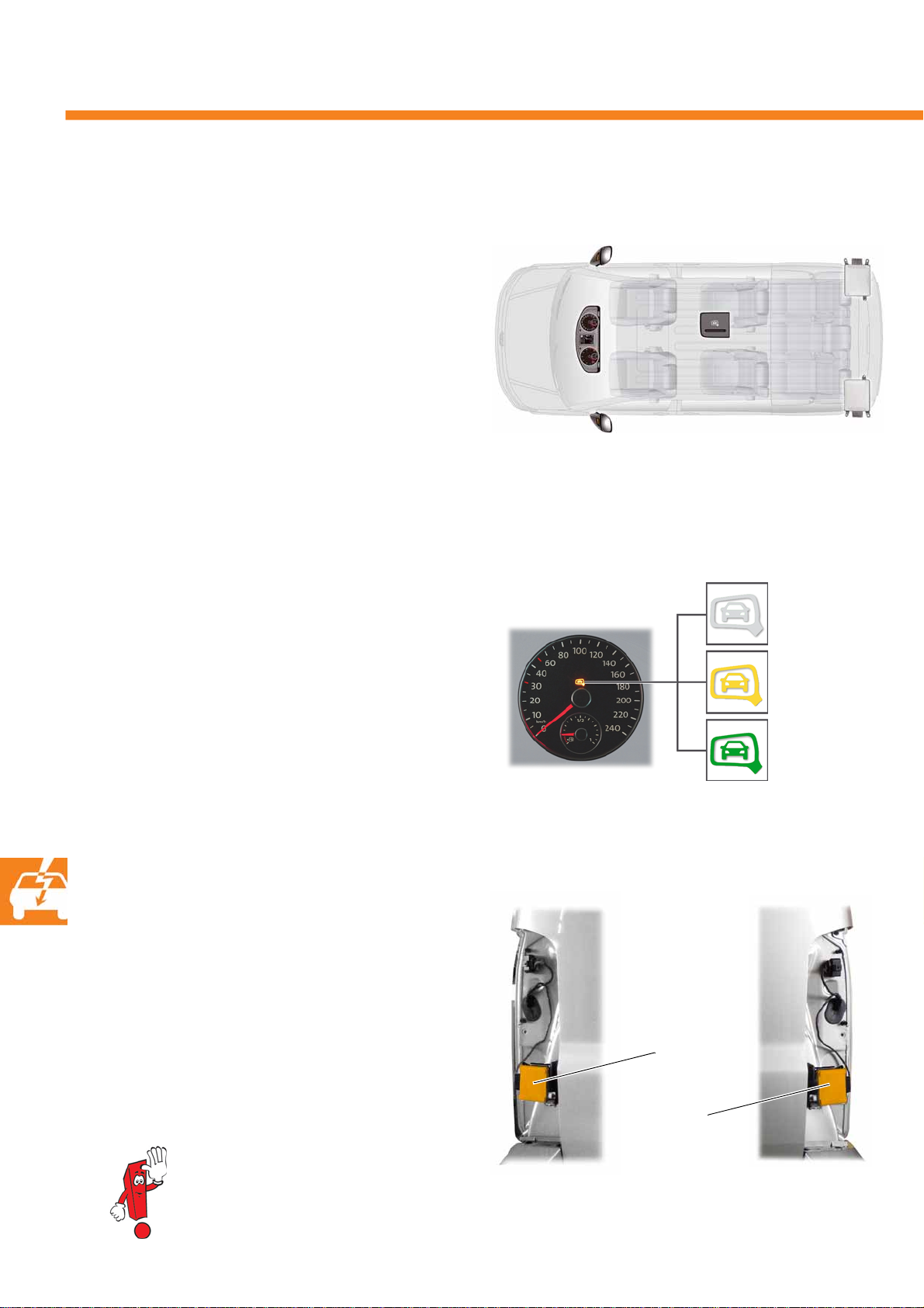
The lane change assist
The T5 2010 (closed bodies, short wheelbase and
tailgate) is now available with lane change assist
(Side Assist) as an option.
Warning light for lane change
assist (front passenger side) K234
Lane change assist control
unit 2 J770
The lane change assist warns the driver about
vehicles that are located to the side in the "blind spot"
or which are approaching rapidly from behind. To
achieve this, two radar sensors scan the adjacent
lanes on either side, both to the side and to the rear of
the vehicle. If the lane change assist detects a critical
situation, the warning light for the lane change assist
(LED system) in the exterior mirror housing on the side
of the vehicle in question indicates that there is a risk.
The system can be switched on and off using a switch
in the centre dash panel or using the multifunction
indicator. The system automatically switches to active
mode at a speed of 30 km/h or more.
The lane change assist warning lamp in the righthand round instrument of the dash panel insert
indicates whether the system is active or passive.
Functions of warning lamp …
● … not lit - system is switched off or there is
an error
● … yellow - system switched on and passive
● … green - system switched on and active
Dash panel
insert
lane change
Lane change assist warning light
(driver side) K233
Warning light for lane change assist
K232 -
function of light …
Button for
assist E530
Lane change assist control
unit J769
S453_071
... not lit
... yellow
... green
S453_110
50
Installation position of the control
units
The lane change assist control units are each installed
behind the cover under the tail light. The sensors are
also integrated in these control units.
For information about the lane change
assist, refer to self-study programme no. 396
"The lane change assist"
rear left rear right
Lane change assist
control unit J769 (left)
Lane change assist
control unit 2 J770
(right)
S453_102S453_101
Page 51
The reversing camera system
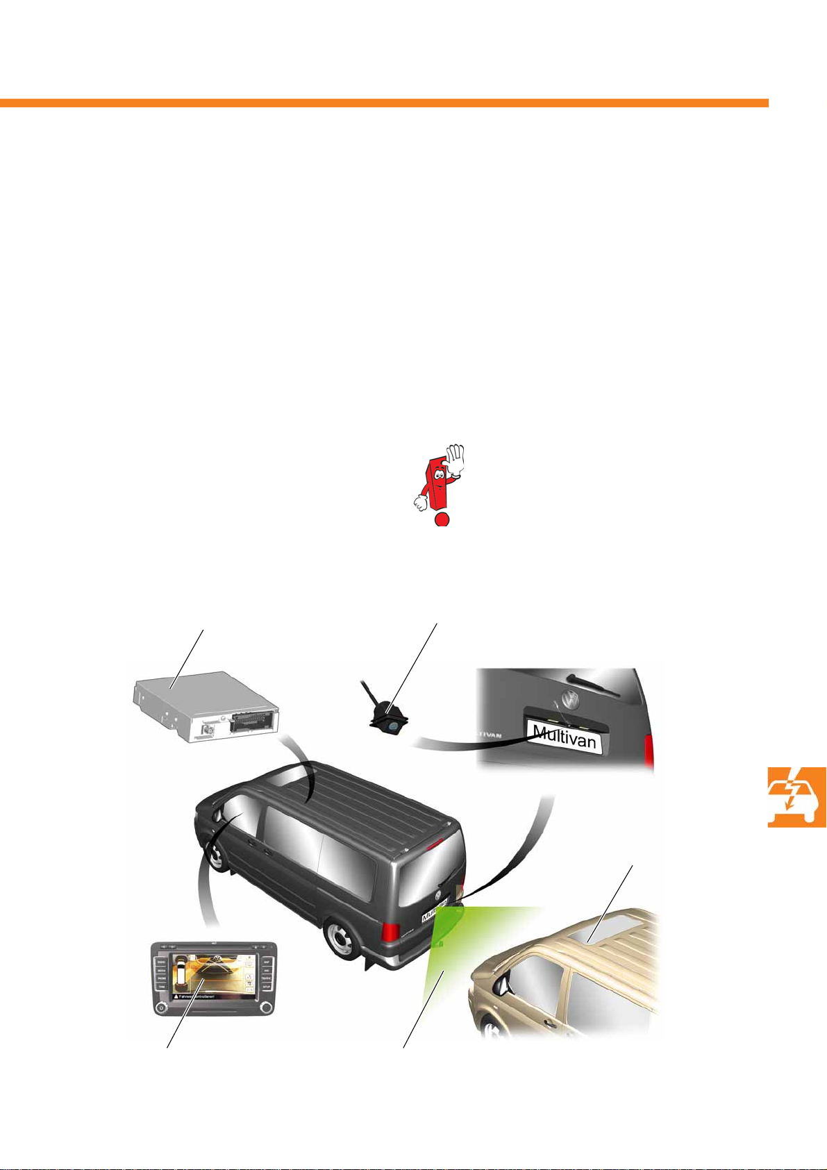
As an extension to the previous, ultrasound-based system for assistance during parking, the T5 2010 with tailgate
can be equipped with the option of a reversing camera system.
The reversing camera system operates with a wideangle camera in conjunction with a control unit.
The camera is fitted in the number plate light.
In the dark, the illumination in the rear area of the
vehicle provided by the reversing light is sufficient
to allow perfect function.
Installation position of system components
reversing camera
The field of view to the rear that can be observed via
the camera is transferred to the control unit installed
in the right seat box and is processed there so that it
can be displayed on the colour display of the
navigation system without distortion and with
superimposed dynamic and static assistance lines.
Detailed information about the reversing
camera system is available in self-study
programme no. 407 "The reversing
camera system".
Reversing cameraControl unit for
Colour display in the radio/
navigation system
Observation area of the
reversing camera
Vehic le i n t h e
observation area of the
reversing camera
S453_103
51
Page 52
Electrics
The dash panel
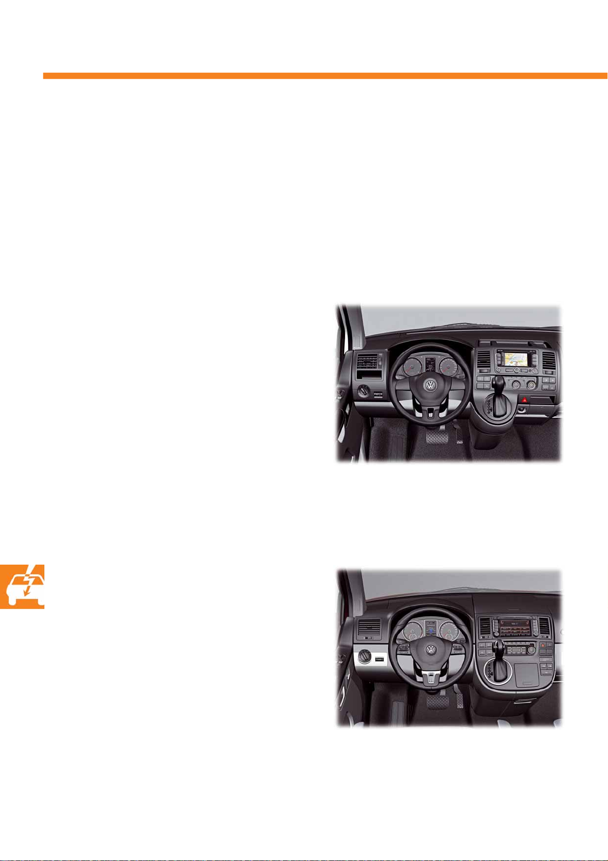
The dash panel has been revised for the T5 2010. Overview of new features: revised lines, surfaces, newly
designed dash panel inserts, completely new radio/navigation range and updated controls for heating/ventilation
and air conditioning systems.
The joystick control in the dash panel has been retained.
Two different equipment versions of the dash panel are installed:
Some models like the Caravelle and platform vans
have the dash panel shown adjacent.
The middle section of the dash panel only has a
narrow downwardly tapering housing contour for
accommodating the joystick control.
Other models, such as the Multivan Highline, feature
the following dash panel.
This dash panel version is extended downwards in the
centre part across the full width of the display units
located above, for the purpose of accommodating the
joystick control and for accommodating other controls
and storage possibilities.
S453_009
S453_008
52
Page 53
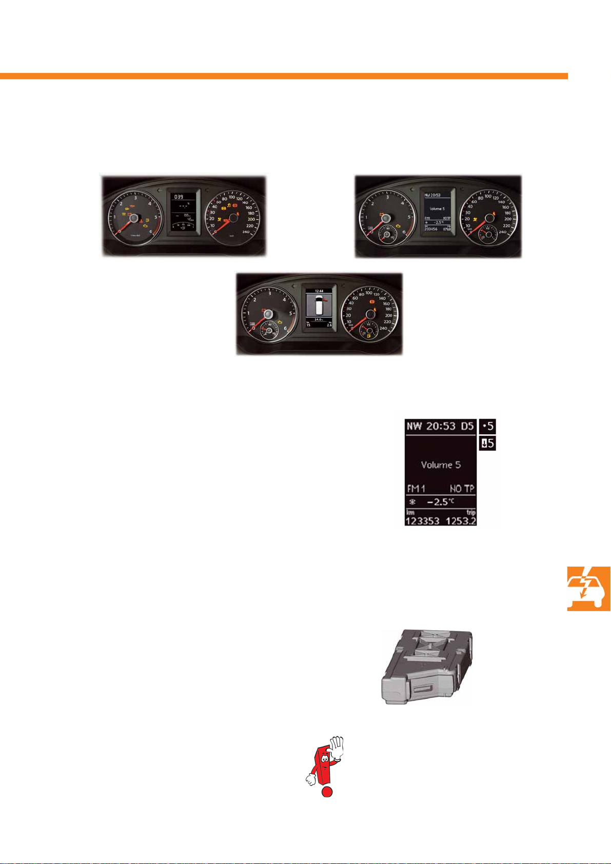
Dash panel insert
Three variants of the dash panel insert are fitted in the T5 2010 depending on the vehicle equipment.
Standard
S453_086
Premium
Medium
Gearshift recommendation
Depending on the equipment, the T5 2010 has a display in the
multifunction indicator of the dash panel insert in order to provide a
recommendation for the driver to change gear in order to drive more
economically.
Arrow = Gearshift recommendation – lower/higher gear
Number = Target gear
Dot = No gearshift recommendation given
(the digit next to the dot shows the currently
engaged gear that corresponds to the optimum
engine revs)
S453_133
S453_134
S453_144
In vehicles with DSG, the engaged drive range and the current gear are displayed.
The media device interface box
The T5 2010 is optionally equipped with the media
device interface box (MDI box). It makes it possible to
connect portable audio and memory devices and to
play back their audio files via the radio or navigation
system.
The media device interface box is fitted on the right
above the pedals. The connection socket installed in
the glove compartment is used for connecting
portable devices.
Detailed information about the media
device interface box can be found in selfstudy programme no. 423 "The Golf 2009".
S453_140
53
Page 54
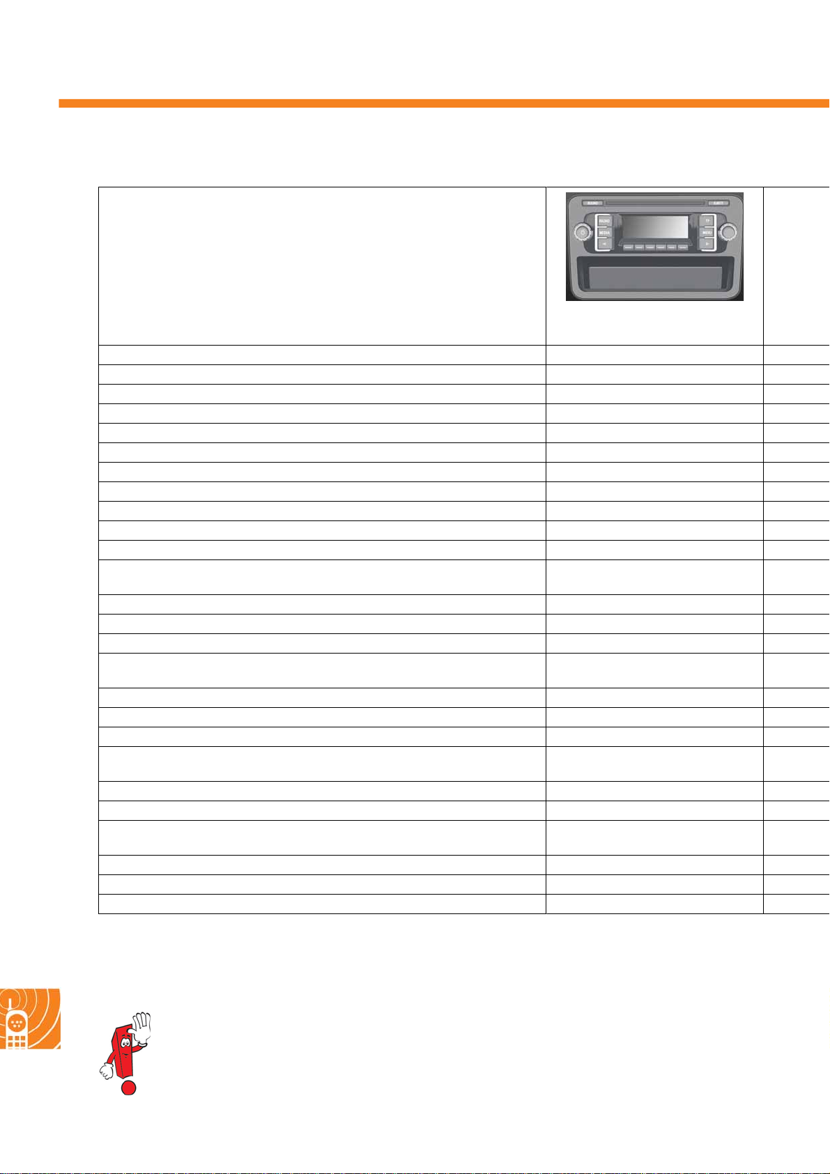
Radio, phone and navigation
The radios and radio navigation systems
Technical data
Monochrome display 122 x 36 pixels
Colour display, touchscreen
FM, TP and RDS reception (single tuner) ●
FM twin tuner for FM, TP and RDS reception with phase diversity
AM reception ●
Integrated DAB tuner (digital radio)
Radio Data System (RDS) ●
TMC function and TMC background reception
Voi ce co ntrol
Integrated CD player ●
Integrated SD memory card reader
Media support CD and MP3 audio data
Audio input interface (AUX-IN) ●
Telephone interface for telephone hands-free device ● (mono channel only)
Interface for connecting a reversing camera
Loudspeaker output stages with 20 watt output
(2 or 4 loudspeakers can be connected)
Treble, bass and balance adjustment ●
Fader setting (only with four loudspeakers) ●
Speed dependent volume adjustment ●
Brightness of display lighting can be controlled
independently from lighting inside vehicle
Self-diagnosis and loudspeaker diagnosis ●
Service test mode ●
Navigation function with map, integrated driving symbols and speech
RCD 210
S453_061
●
●
54
DVD/ SD navigat ion
DVD/ H DD navigat io n
For more information, see self-study programme no. 404
For information about the abbreviations used with the radios and radio/navigation systems, please
refer to self-study programme no. 423 "The Golf 2009".
Page 55
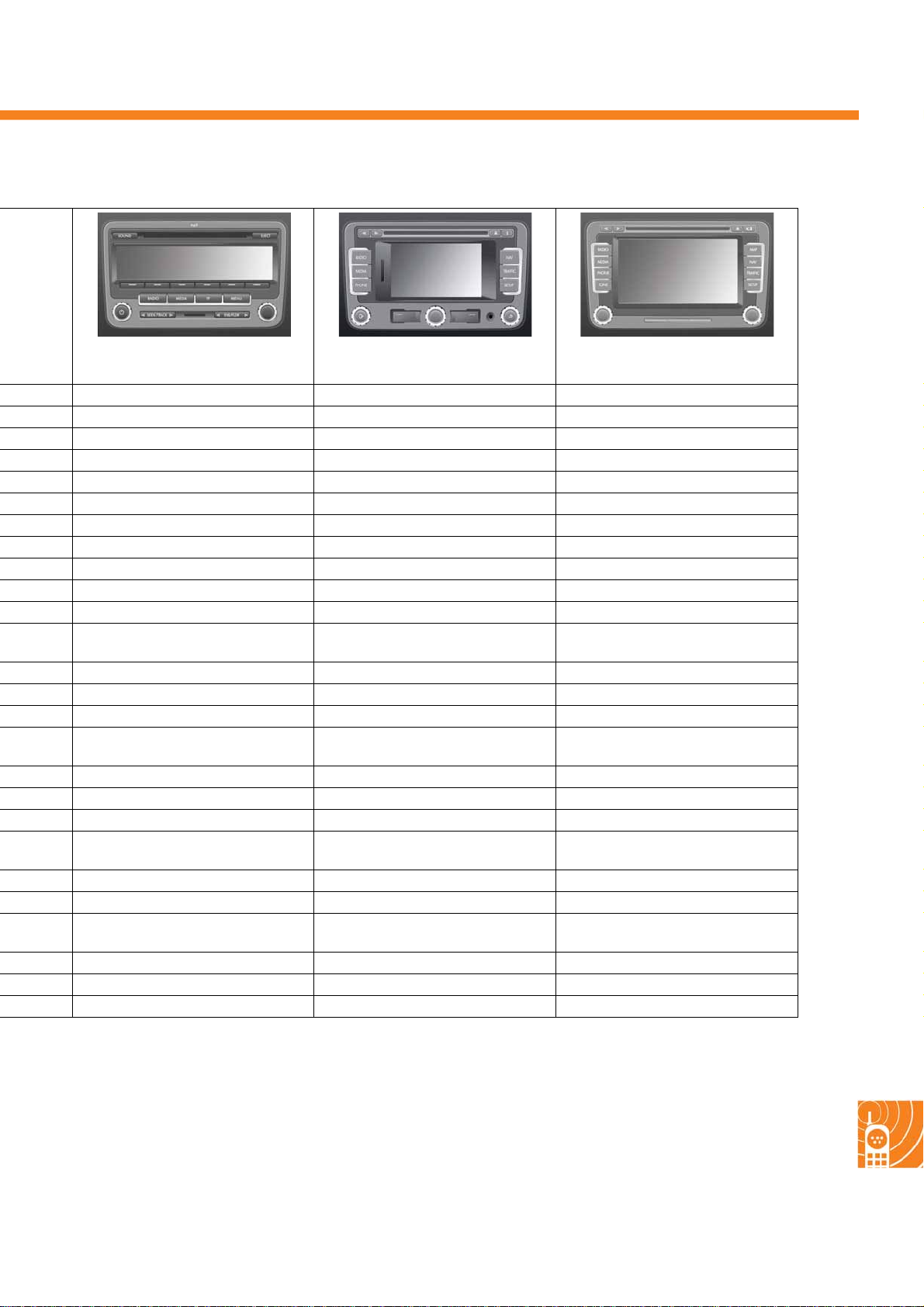
RCD 310 RNS 310 RNS 510
302 x 45 pixels
5.5-inch, 400 x 240 pixels 6.5-inch, 800 x 480 pixels
●●●
●●●
depending on equipment
●●●
●●
●●● (DVD player)
●●
CD, MP3 and WMA audio data CD, MP3 and WMA audio data,
navigation data
●●●
●●●
●●●
●●●
●●●
●●●
CD, MP3 and WMA audio and
DVD video data, navigation data
S453_058S453_060S453_059
●
●
●●●
●●●
●●●
●
Map view (3D)
●
No. 417 No. 423 No. 423
Map view (2D and 3D)
●
●
55
Page 56
Radio, phone and navigation
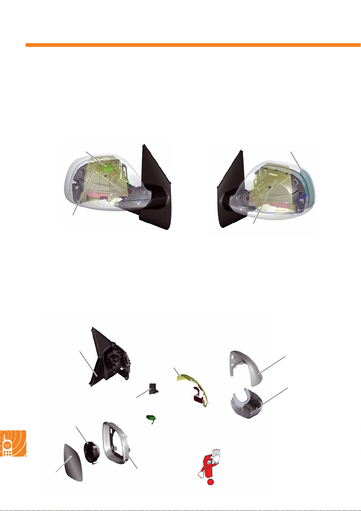
The aerial concept
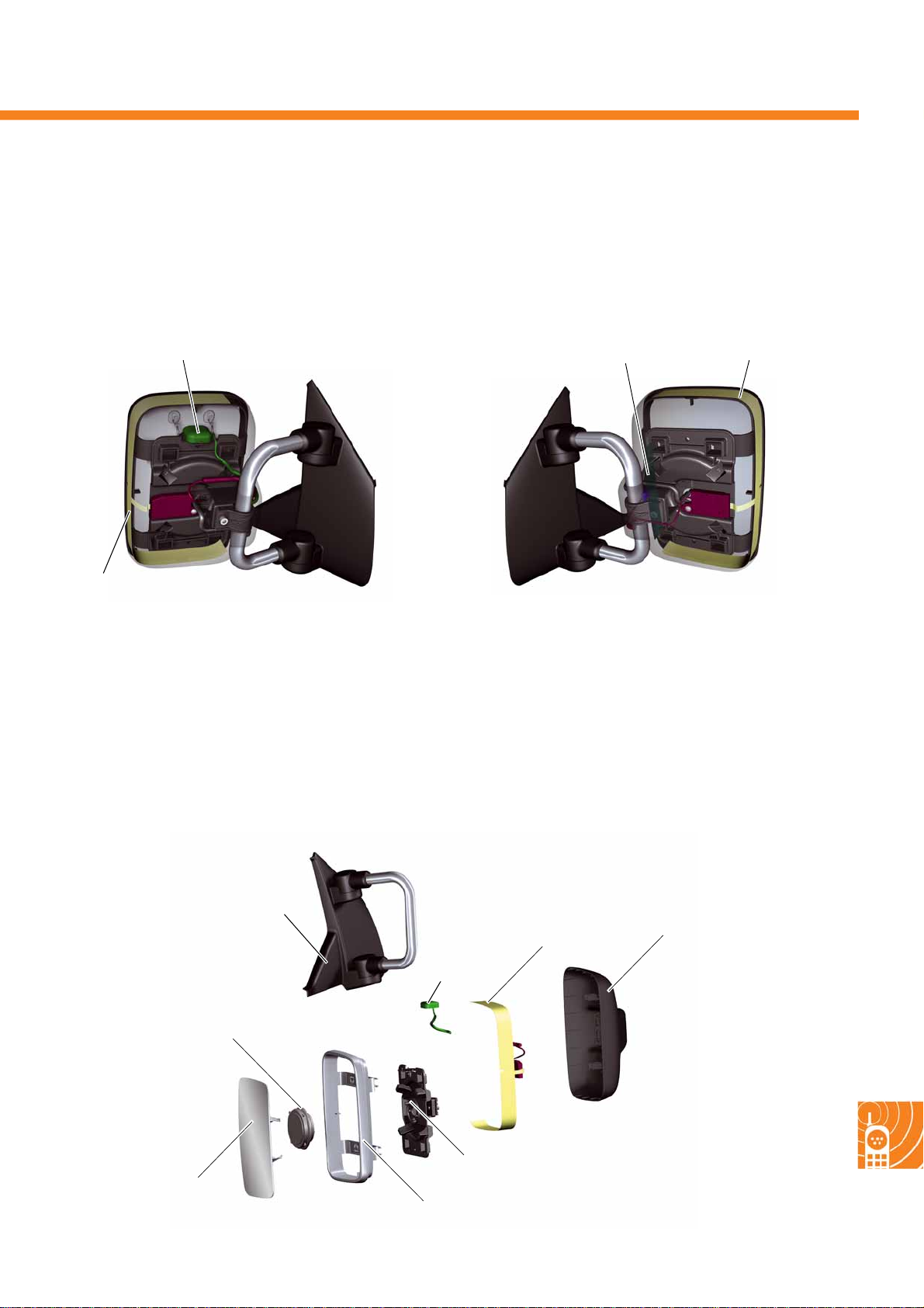
The T5 2010 has a complete aerial system for radio, TV, phone and GPS integrated in the exterior mirrors. The
mirrors are configured as module exterior mirrors or exterior mirrors on extension bars depending on the model
variant.
Module exterior mirrors for closed bodies
GPS GSM
FM2 or FM2/ DAB or
FM2/TV
Right exterior mirror
The signal pathways of the FM2 or FM2/DAB or
FM2/TV aerials are located on a shared aerial foil
in each case.
The GPS aerial is attached to the interior housing of
the exterior mirror.
Exploded view - example of right exterior mirror
Mirror base carrier
Aerial foil
S453_037
AM/FM or
AM/FM/TV
Left exterior mirror
The AM/FM or AM/FM/TV aerials are each located
together on one aerial foil with associated signal
pathways.
The GSM aerial is located on a separate aerial foil.
Mirror housing
Bottom trim
S453_115
56
Adjustment unit
Mirror glass
Warning light for
lane change assist
S453_038
GPS aerial
Please always refer to the information in
the workshop manual for repair work.
Housing frame
Page 57
Exterior mirror on extension bars for open bodies
GPS
FM2 or FM2/DA B
S453_039
Right exterior mirror
The signal pathways of the FM2 or FM2/ DAB aerials
are located on a shared aerial foil in each case. The
GPS aerial is attached to the interior housing of the
exterior mirror. At the moment, no TV aerial is
provided.
GSM
AM/FM
S453_116
Left exterior mirro r
The AM/FM aerial is located on an aerial foil with
associated signal pathways. The GSM aerial is
located on a separate aerial foil on the inside of the
mirror housing.
Exploded view - example of right exterior mirror
Mirror base carrier
Adjustment unit
Mirror glass
GPS
aerial
Housing frame
Aerial foil
Adjustment unit - base plate
Mirror housing
S453_040
57
Page 58
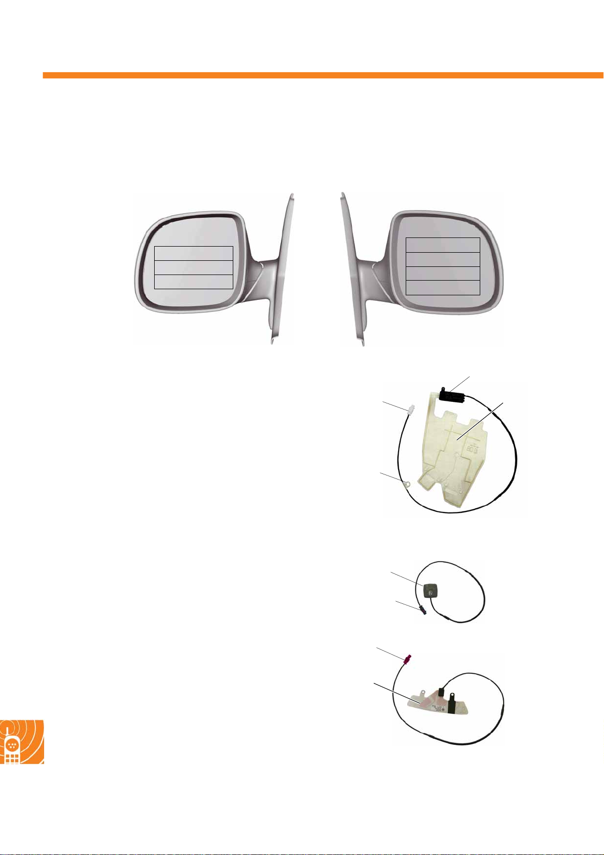
Radio, phone and navigation
Aerial assignment - module exterior mirror
Each of the aerial combinations shown in the picture is possible for the module exterior mirrors.
Exterior mirror
left
AM/FM
AM/FM/GSM
AM/FM/TV/GSM
S453_063
Mirror aerials
AM, FM, DAB, TV aerial with
impedance converter
Aerial foils, impedance converter and aerial cables
are grouped into one component and cannot be
renewed separately.
AM, FM, DAB and TV aerials are phantom powered.
The phantom supply (approx. 12 V) is used for
supplying power to the impedance converter and the
diagnostic function.
Exterior mirror
right
without
FM2
FM2/DAB /GPS
FM2/TV/GPS
S453_062
Impedance converter
Plug connection
Aerial mount
The illustration above shows an FM2 aerial by way of example.
Aerial foil
S453_044
58
GPS aerial
The GPS aerial is secured with an adhesive pad. The
internal electronics are powered via the phantom
supply (5 V).
GPS aerial
Plug connection
Plug connection
GSM aerial
GSM aerial
In the GSM aerial, the phantom supply (12 V) is only
required for the diagnostic capability.
All aerials can be renewed separately. The plug connections are mechanical and colour coded.
S453_065
S453_066
Page 59
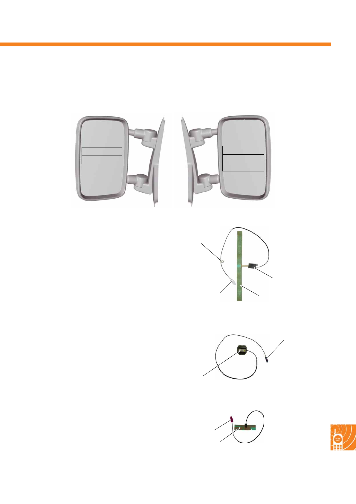
Aerial assignment - exterior mirror on exte nsion bars
Each of the aerial combinations shown in the picture are possible for the exterior mirrors on extension bars.
Exterior mirror
left
AM/FM
AM/FM/GSM
S453_138
Mirr or a e ri al s
AM, FM, DAB aerial with
impeda nc e c onverter
Aerial foils, impedance converter and associated
cables form one component.
The exterior mirror can be dismantled without
damaging it.
S453_139
Aerial mount
Plug connection
Exte ri o r m i rr o r
right
without
FM2
FM2/ DAB /GPS
S453_064
Impedance
converter
Aerial foil
The aerial foils are attached in the exterior mirror by
glue points.
GPS aerial
Plug connection
The GPS aerial is located on a magnetic holder.
This is screwed onto the inside of the mirror housing.
All plug connections are mechanical and colour
coded.
GPS aerial
GSM aerial
The GSM aerial is attached to the inside of the mirror
housing by glue.
Regarding the phantom supply and diagnostic capability, please refer to the module exterior mirror.
Plug connection
GMS aerial
S453_067
S453_068
59
Page 60
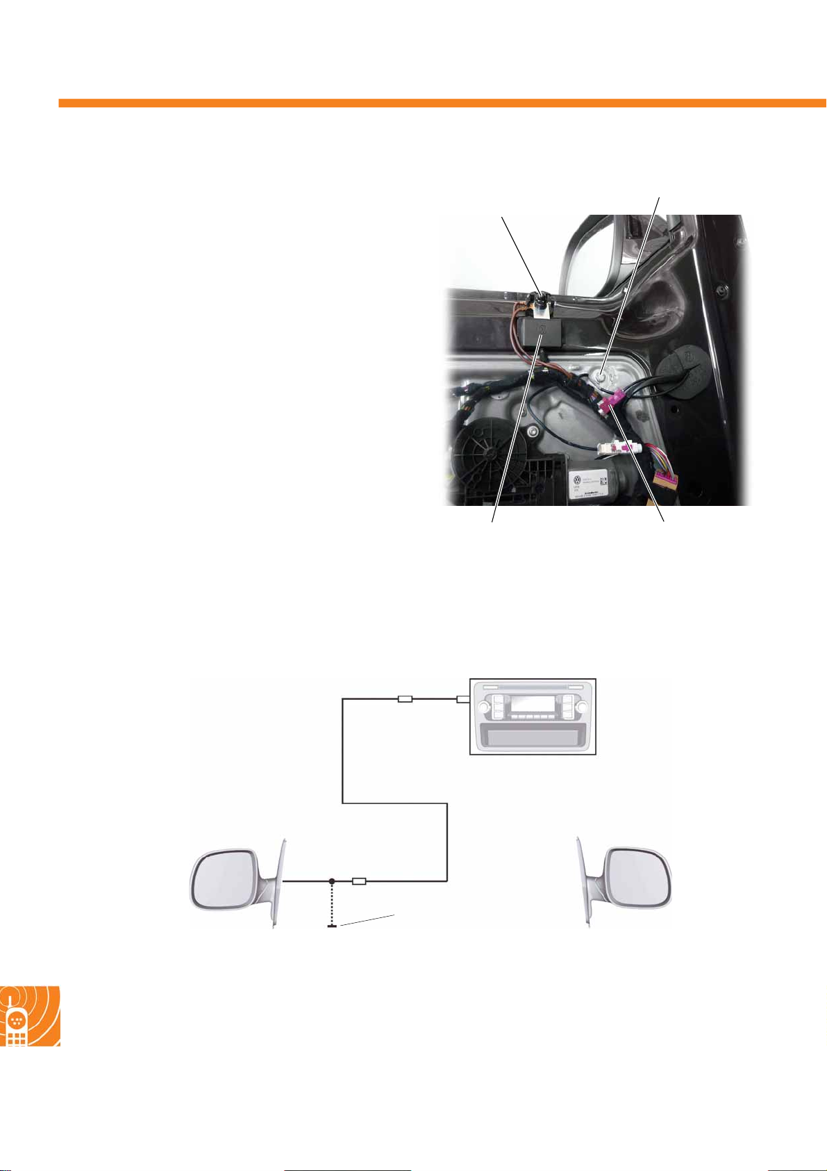
Radio, phone and navigation
Aerial - onboard power supply
connection
The AM, FM, TV and DAB aerials need antenna
mounts that are located inside the doors. To ensure a
perfect earth connection to the doors, the doors have
an earth connection to the body earth via a separate
earth cable.
Interference in the AM reception area is minimised in
accordance with the vehicle equipment by installing
an AM filter for all electrical connections to
components that are located inside the exterior
mirror (exterior mirror heater, adjustment, etc.).
The AM filter is part of the door cable kit.
Aerial mount
Earth pin with
body earth
The AM aerial is always located in the left exterior
mirror, therefore no filter is required on the right side.
Aerials - radio preparation
AM interference
suppression filter
BB
AM/FMB
Aerial coupling points
S453_141
Left exterior mirror
–AM/FM aerial
60
Aerial mount
S453_050
Right exterior mirror
–without aerials
Page 61
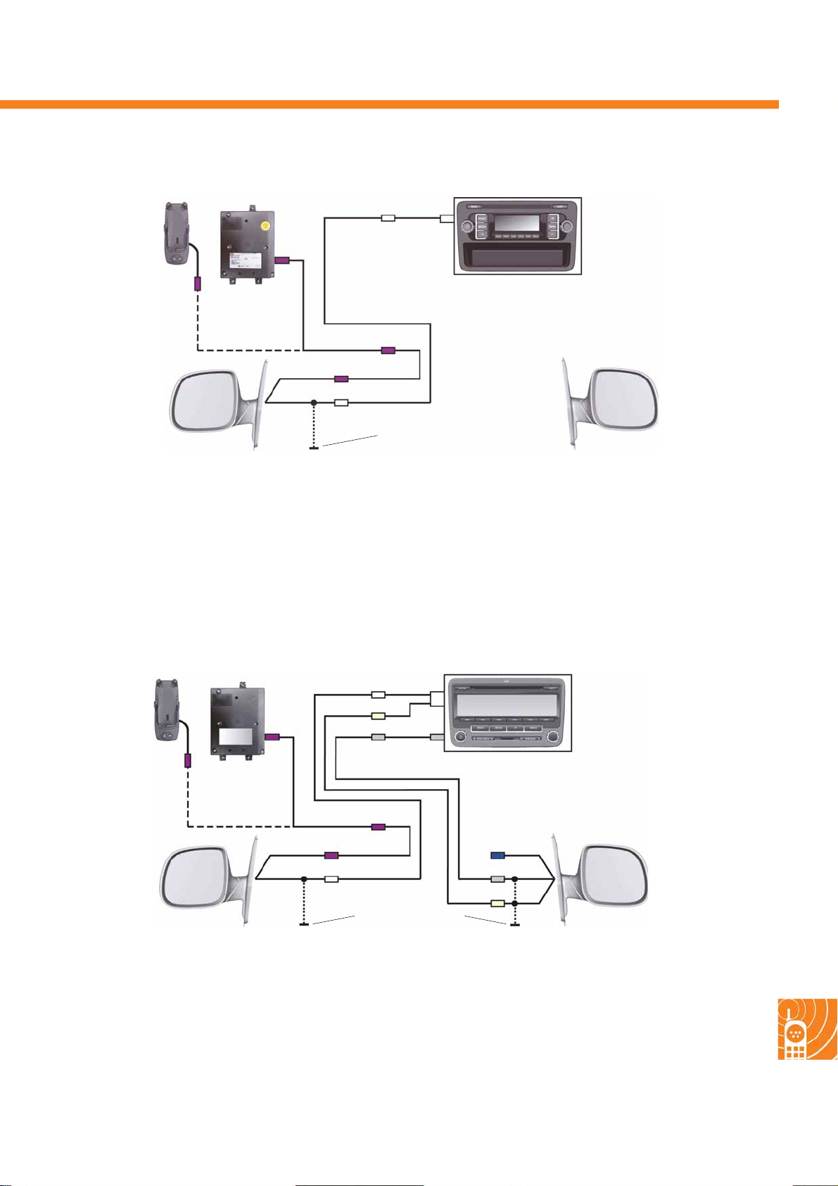
Aerials - radio RCD 210 and UHV
UHV
D
D
RCD210
BB
D
D
BAM/FM
GSM
Aerial mount
Left exterior mirror
–AM/FM aerial
–GSM aerial (with UHV)
Aerials - radio RCD 310 and UHV/DAB
UHV
D
D
I
A
S453_046
Right exterior mirror
–without aerials
RCD310
BB
A
Left exterior mirr or
–AM/FM aerial
– GSM aerial (with UHV)
D
D
GSM
BAM/FM
Aerial mount
Right exterior mirror (w ith DAB)
– FM2/DAB aerial
– GPS aerial (not used)
Right exte rior mirror (in equipment wi thout DAB)
–FM2 aerial
CAGPS
DAB
I
FM
456_047
61
Page 62
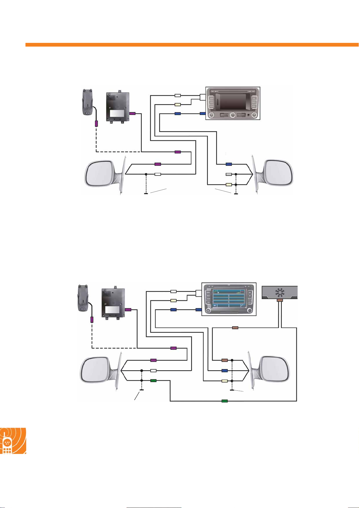
Radio, phone and navigation
Aerials - radio/navigation unit RNS 310 and UHV
BB
UHV
D
I
C
C
D
Left exterior mirror
– AM/FM aerial
–GSM aerial (with UHV)
B
D
D
GSM
AM/FM
Aerial mount
Right exterior mirror
– FM2/DAB aerial (DAB aerial is not used)
– GPS aerial
RNS 310
C
GPS
A
DAB
I
FM
Aerials - radio/navigation unit RNS 510 and UHV/TV
RNS 510
BB
UHV
D
I
C
C
456_048
TV tuner
F
62
D
Left exterior mirror
–AM/FM/TV aerial
–GSM aerial
Aerial mount
D
B
E
D
GSM
AM/FM
TV
F
FCTV
GPS
I
FM
E
Right exterior mirror
–FM2/TV aerial
– GPS aerial
Aerial mount
456_049
Page 63
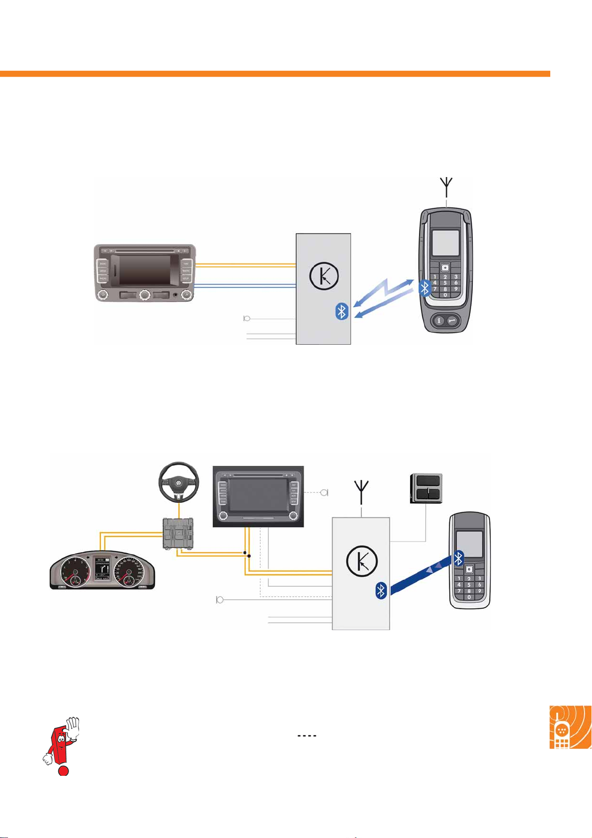
The telep h on e preparation UHV
The telephone preparations used in the T5 2010 are UHV with audio streaming and UHV premium. These must be
paired with Bluetooth
UHV (BluetoothTM low) with audio streaming
TM
-capable mobile phones.
CAN data bus
J503
Stereo channels
R38
Term i nal 3 0
Te r m inal 3 1
Key
J412 Mobile telephone operating electronics control unit
J503 Control unit with display for radio and navigation
R38 Telephone microphone
UHV premium with Bluetooth
E440 E441
LIN data bus
J285
J519
TM
(rSAP)
J503
J412
Bluetooth
R38
TM
voice data
J412
Only
via HFP
Music data
A2DP
3-button module
S453_053
Telephone holder
CAN data bus
R38
Term i n al 30
Term i nal 3 1
Key
E440 Multifunction buttons in steering wheel left
E441 Multifunction buttons in steering wheel right
R38 Telephone microphone
More detailed information about the
UHV telephone preparations is available
in self-study programme no. 423
"The Golf 2009".
Audio
S453_051
Bluetooth
TM
rSAP mobile phone
J285 Control unit in dash panel insert
J412 Mobile telephone operating electronics control
unit
J503 Control unit with display for radio and
navigation
only with RNS 510
63
Page 64
453
© VOLKSWAG E N AG, Wolfsburg
All righ ts re se rved. Subje c t to tec h ni c al mo di fications .
000.2812.33.2 0 Techni cal status 11.2 009
Volkswagen AG
After Sal es Qualifizierung
Service Training VSQ-1
Brieffach 1995
D-38436 Wolfsburg
❀ Paper made from cellulose bleached without the use of chlorine.
 Loading...