

Volkswagen Jetta (1998), Jetta (1999), Jetta (2000), Jetta (2001), Jetta (2002) Service Manual
...Page 1

Note:
For Guided Fault Finding information, refer to VAS 5051 Diagnostic Tester
01 - On Board Diagnostic (OBD)
ABS ITT Mark 20 IE On Board Diagnostic (OBD)
Function
Identifying characteristics
Technical data
Safety precautions
On Board Diagnostic (OBD) with V.A.G 1551 Scan Tool or Tester VAS 5051 (flow chart)
Electrical/electronic components and locations
Diagnostic Trouble Codes (DTC) displayed by warning lights
-K14-, -K47- and -K118-
ABS ITT Mk 20 IE On Board Diagnostic (OBD) program
V.A.G 1551 Scan Tool, connecting and selecting function
Diagnostic Trouble Code (DTC), memory
Automatic test sequence
Vehicle Diagnosis, Testing and Information System VAS 5051, connecting and se lecting ABS
control module
Diagnostic Trouble Code (DTC) table
Diagnostic Trouble Code (DTC) memory, erasing and ending output
ABS control module, coding
Measured value block, reading
Safety precautions
Output Diagnostic Test Mode (DTM)
Basic setting, initiating
ABS, ABS/EDL and ABS/EDL/ASR ITT Mark 20 IE, electrical check
Multi
-pin connector with contact assignment
Test table
Brake light switch, adjusting
ABS Mark 60 On Board Diagnostic (OBD), vehicles from my 10.00
Function
Arrangement of ABS MARK 60
Technical data
Safety precautions and fundamental points regarding troubleshooting
Troubleshooting with V.A.G 1551 scan tool or tester VAS 5051 on ABS Mark 60 (flow chart)
Electrical/electronic components and installing locations
Diagnostic Trouble Codes (DTCs) displayed by warning lights
-K47-, -K118- and -K155-
On Board Diagnostic (OBD), performing
Test prerequisites for OBD
Safety precautions
Scan tool, connecting
V.A.G 1551 scan tool, connecting and selecting function
List of selectable functions
Automatic test sequence
Diagnostic Trouble Code (DTC) memory, checking
Output Diagnosic Test Mode (DTM)
Diagnostic Trouble Code (DTC) table
Diagnostic Trouble Code (DTC) memory, erasing and ending output
ABS control module, coding
Vehicle data label
Measured value block, reading
Output Diagnosic Test Mode (DTM)
Basic setting, initiating
Login procedure
Electrical check of Mark 60
Multi
-pin connector with contact assignments
Test table (test steps 1
- 16)
Test table (test steps 17
- 23)
Definitions
Volkswagen Golf 4 / Bora (1998-2005), GTI / Jetta (1998-2005), R32
(A4)
Page 2

01-1
ABS ITT Mark 20 IE On Board
Diagnostic (OBD)
Function
Since the control modules are interconnected
with CAN-bus, always begin OBD by checking
the Diagnostic Trouble Code (DTC) memories
of all the control modules in the vehicle.
This occurs in the Automatic test sequence and
is activated with key function 00.
When doing this, check to see if there are
DTCs stored which may influence the ABS.
On Board Diagnostic (OBD) relates to the
electrical/electronic part of the ABS, i.e. only
malfunctions via the electrical connection to the
control module are recognized (e.g. speed
sensor open circuit).
The 25-pin ABS Control Module (w/EDL) -J104-
forms with the hydraulic unit a compact unit.
The unit is located on the left in the engine
compartment. The control module is equipped
with a DTC memory. The diagnostic connection
is located in the center console below the
heating/air conditioning controls.
The control module recognizes malfunctions
during vehicle operation and stores them in a
permanent memory, the contents of which
remain even during periods of no battery
voltage.
Стр. 1 из 8ABS ITT Mark 20 IE On Board Diagnostic (OBD
)
Page 3

01-2
Sporadic (isolated) malfunctions will also be
recognized and stored. But if these malfunctions
do not occur again within the next 50 vehicle
starts and driving off sequences then, with the
exception of "control module inoperative", the
DTC memory will be erased.
After switching on the ignition and/or starting the
engine the ABS warning light -K47- and the
warning light for brake system -K118- light up for
approx. 2 seconds.
During this period a test sequence (self-check) is
run in the control module for the following
functions:
To check if the supply voltage is at least 10.0
Volt
To check control module including the valve
windings
To check the coding of the control module
A static check of the speed sensor (no speed
signal)
If after driving off and exceeding a speed of
approx. 20 km/h (approx. 13 mph) the speed
signal is not OK. The ABS warning light -K47will light up again.
Стр. 2 из 8ABS ITT Mark 20 IE On Board Diagnostic (OBD
)
Page 4

01-3
V.A.G 1551 Scan Tool or tester VAS 5051
The On Board Diagnostic (OBD) must be
initiated always at the commencement of
troubleshooting. Electrical malfunctions which
influence the braking characteristics will be
stored. They can be checked with the V.A.G
1551 Scan Tool or with the tester VAS 5051.
The information displayed is used in
conjunction with a DTC table which has
information on the possible DTC causes for
repair measures.
Стр. 3 из 8ABS ITT Mark 20 IE On Board Diagnostic (OBD
)
Page 5
01-4
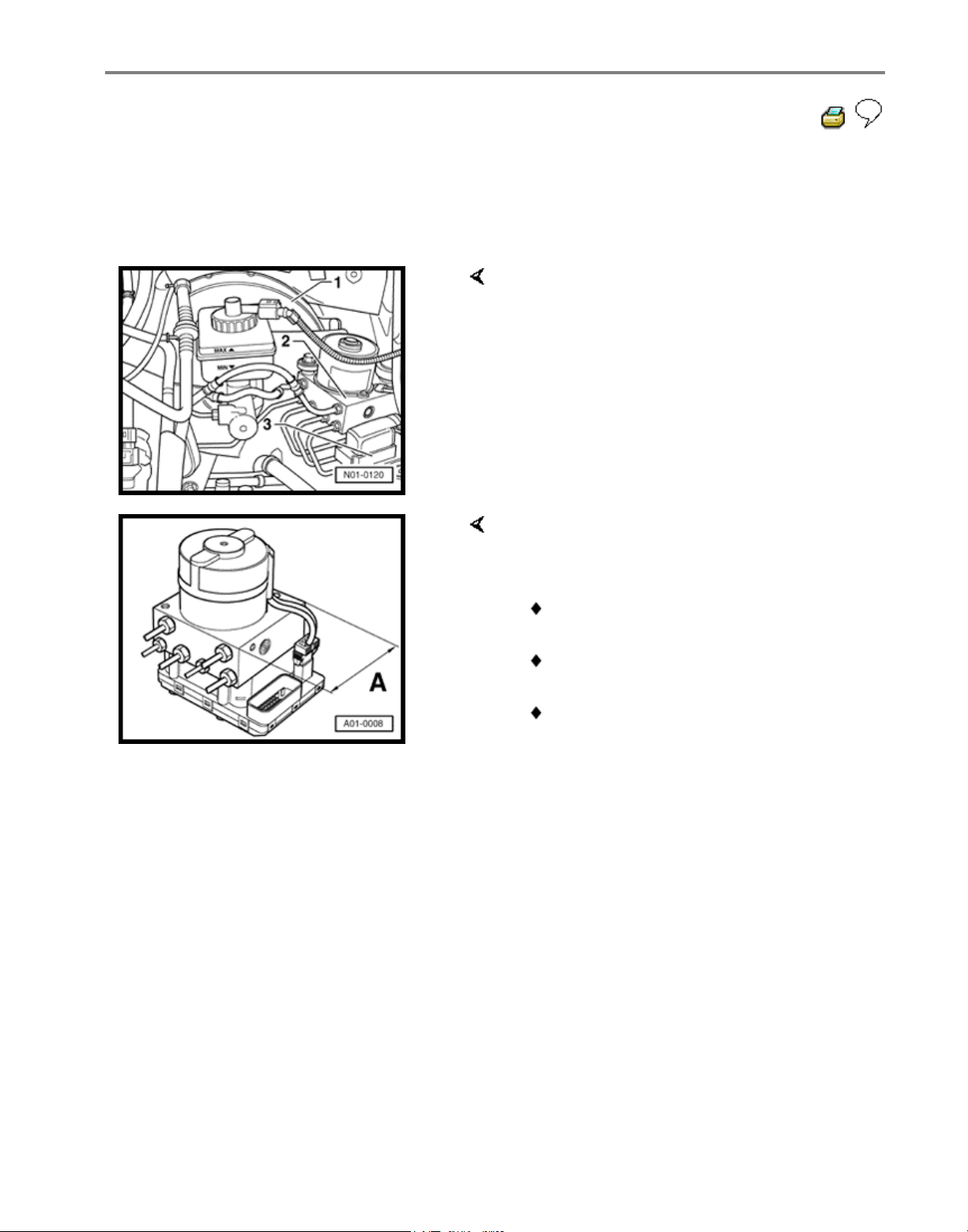
Identifying characteristics
The brake booster boost is produced by
vacuum pressure.
Distinguishing features:
1 - 10" brake booster
2 - Hydraulic unit
3 - Control module, 25-pin (bolted to
hydraulic unit)
Distinguishing features of ABS,
ABS/EDL and ABS/EDL/ASR ITT Mark 20
IE hydraulic unit
Dimension -A- 100 mm vehicles with
ABS
Dimension -A- 130 mm vehicles with
ABS/EDL
Dimension -A- 130 mm vehicles with
ABS/EDL/ASR
Стр. 4 из 8ABS ITT Mark 20 IE On Board Diagnostic (OBD
)
Page 6

01-5
Technical data
Control module identification
The control module version is displayed when
the V.A.G 1551 Scan Tool or the tester VAS
5051 is connected and the control module for
brake electronics is selected Page 01-23 .
1J0 907 379 D / G - ABS
1J0 907 379 E / H - ABS/EDL
1J0 907 379 R / J - ABS/EDL/ASR
Diagnostic Trouble Code (DTC) memory
A non-volatile memory ensures that the
contents of the DTC memory are retained even
without a voltage supply.
Data outputis achieved in operating mode 1
(rapid data transfer).
Стр. 5 из 8ABS ITT Mark 20 IE On Board Diagnostic (OBD
)
Page 7

01-6
Safety precautions
The ABS is a vehicle safety system; the
appropriate knowledge is necessary to work on
the system.
In order to check complaints and to be able to
carry out pin-pointed troubleshooting, the
Diagnostic Trouble Code (DTC) memory must
be checked before beginning work on the ABS
system.
Only separate connectors when the ignition is
switched off.
Observe the appropriate instructions regarding
the handling of brake fluid.
Repair Manual, Brake System, Repair Group
47
ABS malfunctions are indicated by the ABS
warning light illuminating. Certain malfunctions
will only be recognized at speeds above 20
km/h (approx. 13 mph) (carry out road test).
If the ABS Warning Light -K47- and the warning
light for brake system -K118- do not light up,
but the brake system is not functioning correctly
then the malfunction must be sought in the
conventional braking system.
Repair Manual, Brake System; Repair Group
45
Стр. 6 из 8ABS ITT Mark 20 IE On Board Diagnostic (OBD
)
Page 8
01-7
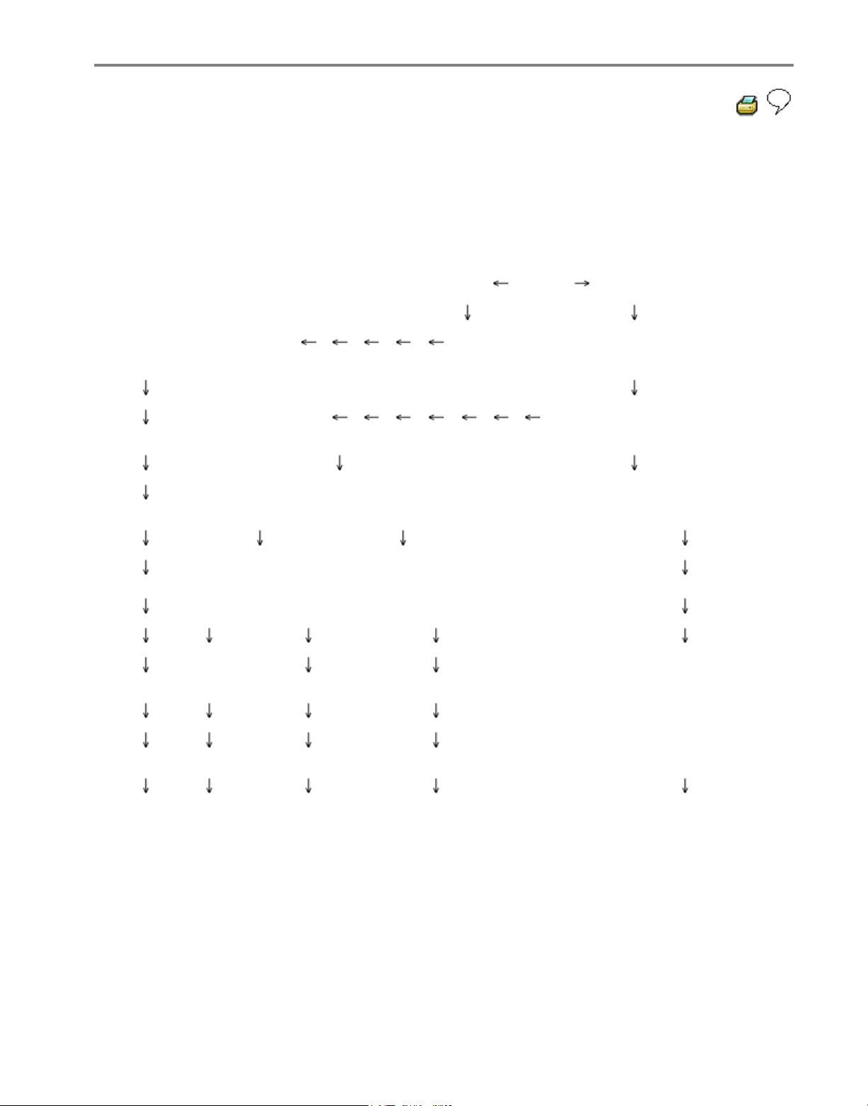
On Board Diagnostic (OBD) with V.A.G 1551 Scan Tool or Tester VAS 5051
(flow chart)
Connect V.A.G 1551 and select 1-rapid
datatransfer
or
Connect tester
VAS 5051 and
select vehicle OBD
Compare control
module identification
Select address word 03-Brake
electronics
Check DTC memory
02
Repair DTCs using DTC table No DTCs
recognized
Read measured
value block 08
Perform output Diagnostic
Test Mode (DTM) 03
Replace
component
1. Perform test drive at more than
20 km/h
2. Check DTC memory 02 again
3. "No DTCs recognized" is
displayed again
A B C
D
E
Стр. 7 из 8ABS ITT Mark 20 IE On Board Diagnostic (OBD
)
Page 9
01-8
A B
C
D
E
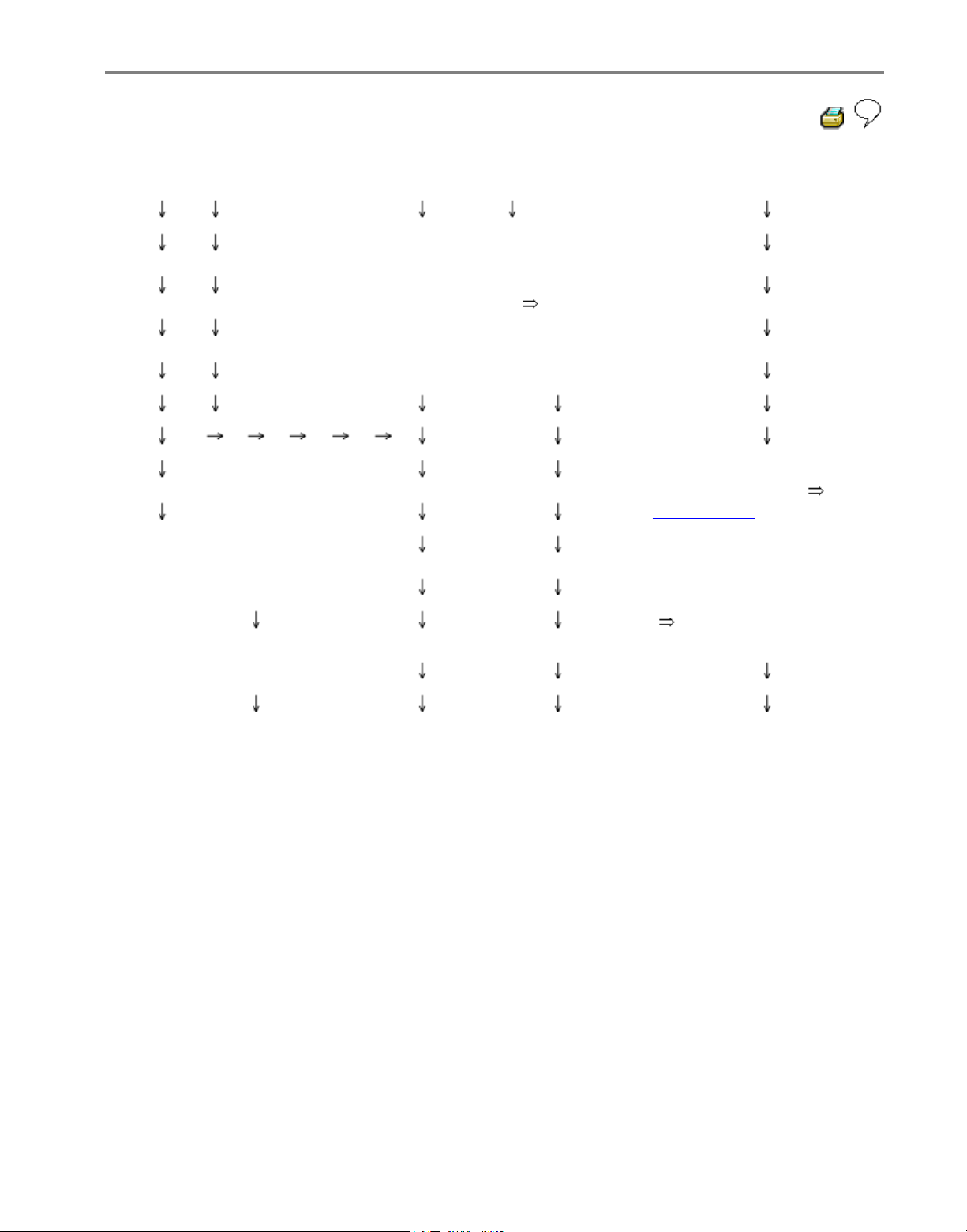
Perform directed
entry of electrical
tests
Service
hydraulic/mechanical
parts of brake system (
Repair Manual)
1. Perform all test steps
of electrical checks
Page 01-102
Identification not OK.
2. Service
hydraulic/mechanical
parts of brake system
( Workshop
Manual)
Replace control module
- Connect V.A.G 1551 and check DTC memory again (02).
- Erase DTC memory (05)
- Perform test drive at more than 20 km/h (13 mph) and allow the ABS to
regulate braking.
- Check DTC memory again after test drive. If "No DTC recognized" appears
on display of V.A.G 1551 after repairing DTCs and performing test drive the On
Board Diagnostic (OBD) is completed.
Стр. 8 из 8ABS ITT Mark 20 IE On Board Diagnostic (OBD
)
Page 10
Electrical/electr
o
components an
d
locations
Repair Manual, Brake
System, Repair Group 45
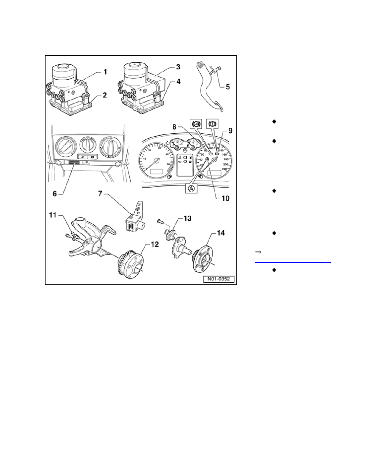
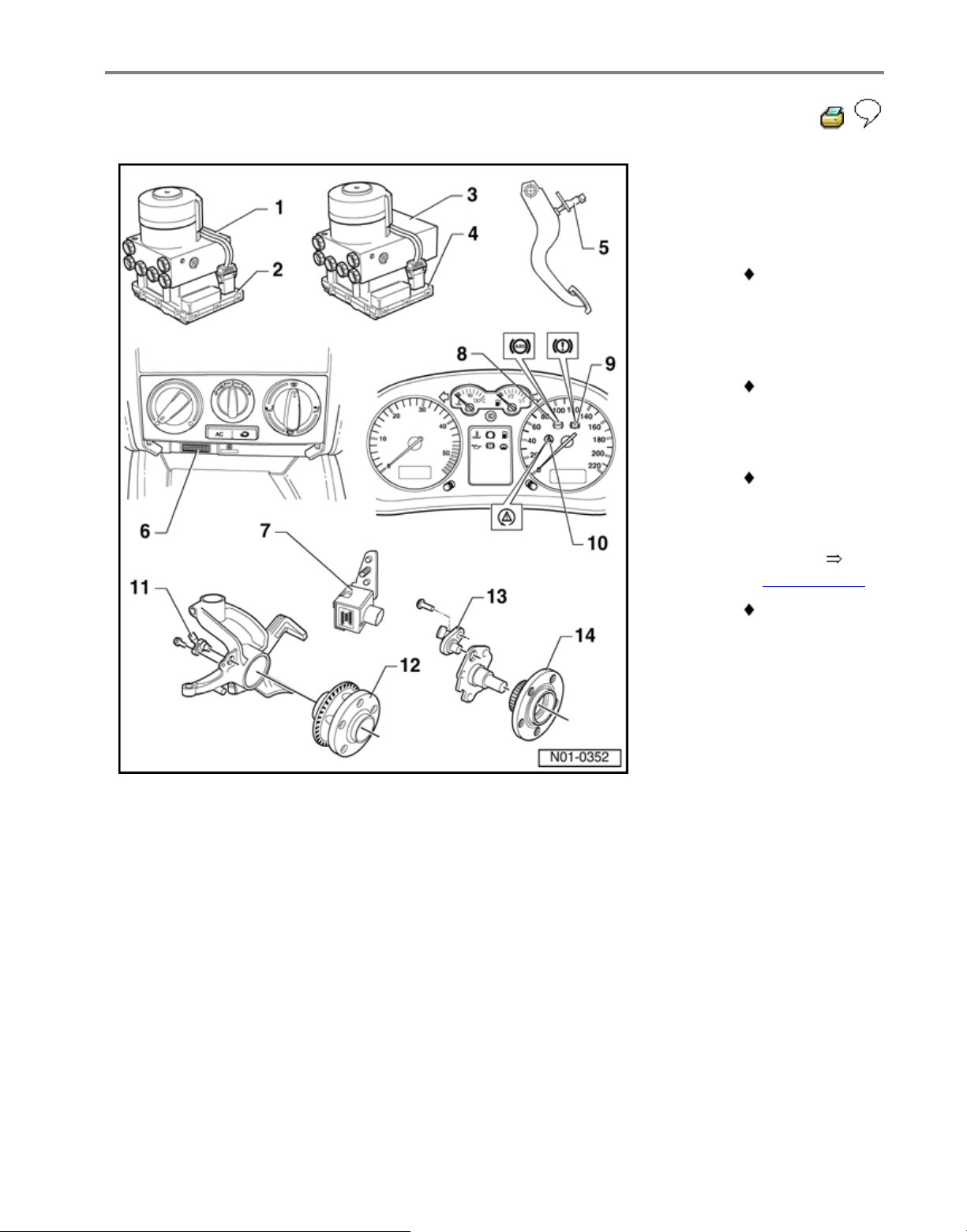
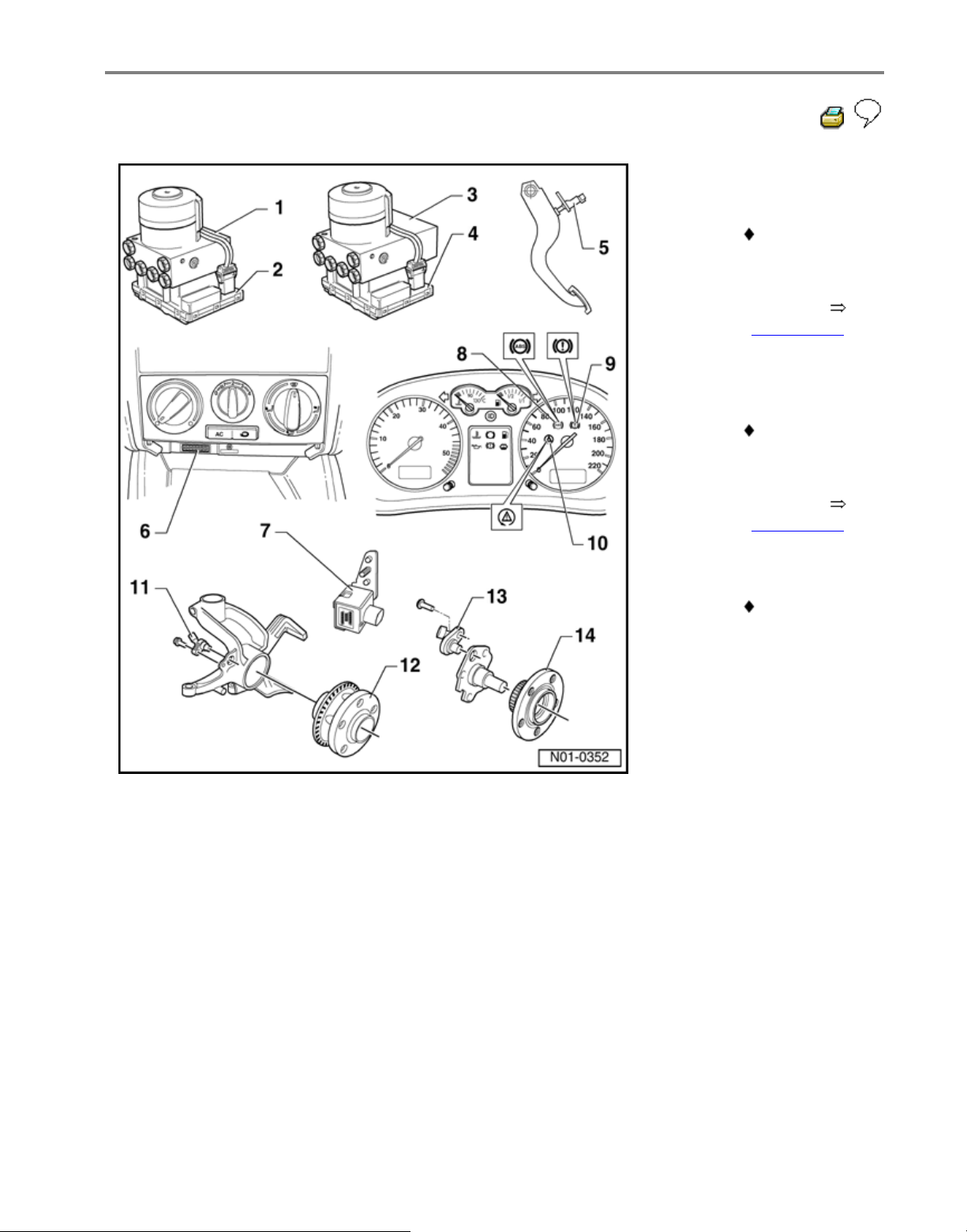
1 - ABS hydraulic unit
N55-
Located on left of
engine compartm
e
The ABS hydrauli
c
pump -V64- and t
h
inlet/outlet valves
i
hydraulic unit are
checked by On B
o
Diagnostic (OBD)
The ABS Hydrauli
c
Pump -V64- and
v
block must not be
separated from o
n
another
Removing and
installing:
When changing th
hydraulic unit, alw
a
seal the old part
w
the plugs from the
repair set Part No.
698 311 A
Стр. 1 из 14Electrical/electronic components and locations
Volkswagen Technical Site: http://volkswagen.msk.ru http://vwts.info http://vwts.ru
огромный архив документации по автомобилям Volkswagen, Skoda, Seat, Audi
Page 11
01-10
2 - ABS control
module
(w/EDL) J104-
Location: on
hydraulic unit
on left of
engine
compartment
Checked by
On Board
Diagnostic
(OBD)
Checking the
multi-pin
connector to
control
module
Page 01-106
Do not
disconnect
connector
before
successfully
completing
OBD. Switch
ignition off
before
separating
connection.
Стр. 2 из 14Electrical/electronic components and locations
Page 12
01-11
Repair Manual,
Brake System,
Repair Group 45
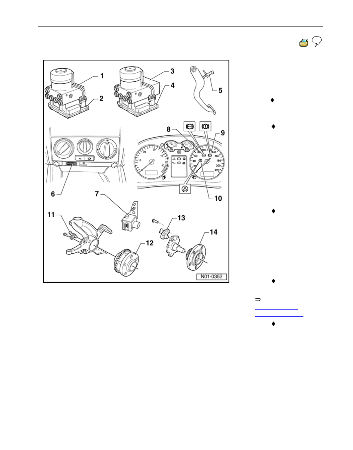
3 - ABS/EDL and
ABS/EDL/ASR
hydraulic unit
-N55-
Located on
left of engine
compartment.
The ABS
hydraulic
pump -V64and the
inlet/outlet
valves in the
hydraulic unit
are checked
by On Board
Diagnostic
(OBD)
The ABS
hydraulic
pump -V64and valve
block must
not be
separated
from one
another
Removing
and installing
When
changing the
hydraulic
unit, always
seal the old
part with the
plugs from
the repair set
Part No. 1H0
698 311 A
Стр. 3 из 14Electrical/electronic components and locations
Page 13
01-12
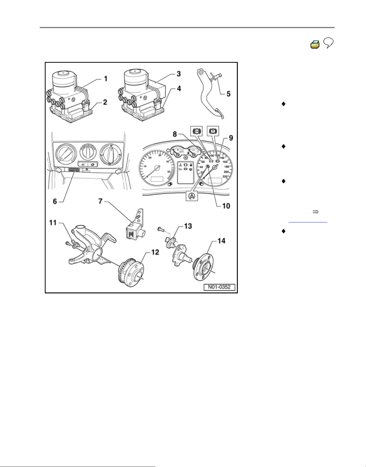
4 - ABS/EDL and
ABS/EDL/ASR
Control
Module -J104-
Location: on
hydraulic unit
on left of
engine
compartment
Checked by
On Board
Diagnostic
(OBD)
Checking the
multi-pin
connector to
control
module
Page 01-106
Do not
disconnect
connector
before
successfully
completing
OBD. Switch
ignition off
before
separating
connection.
Стр. 4 из 14Electrical/electronic components and locations
Page 14
01-13
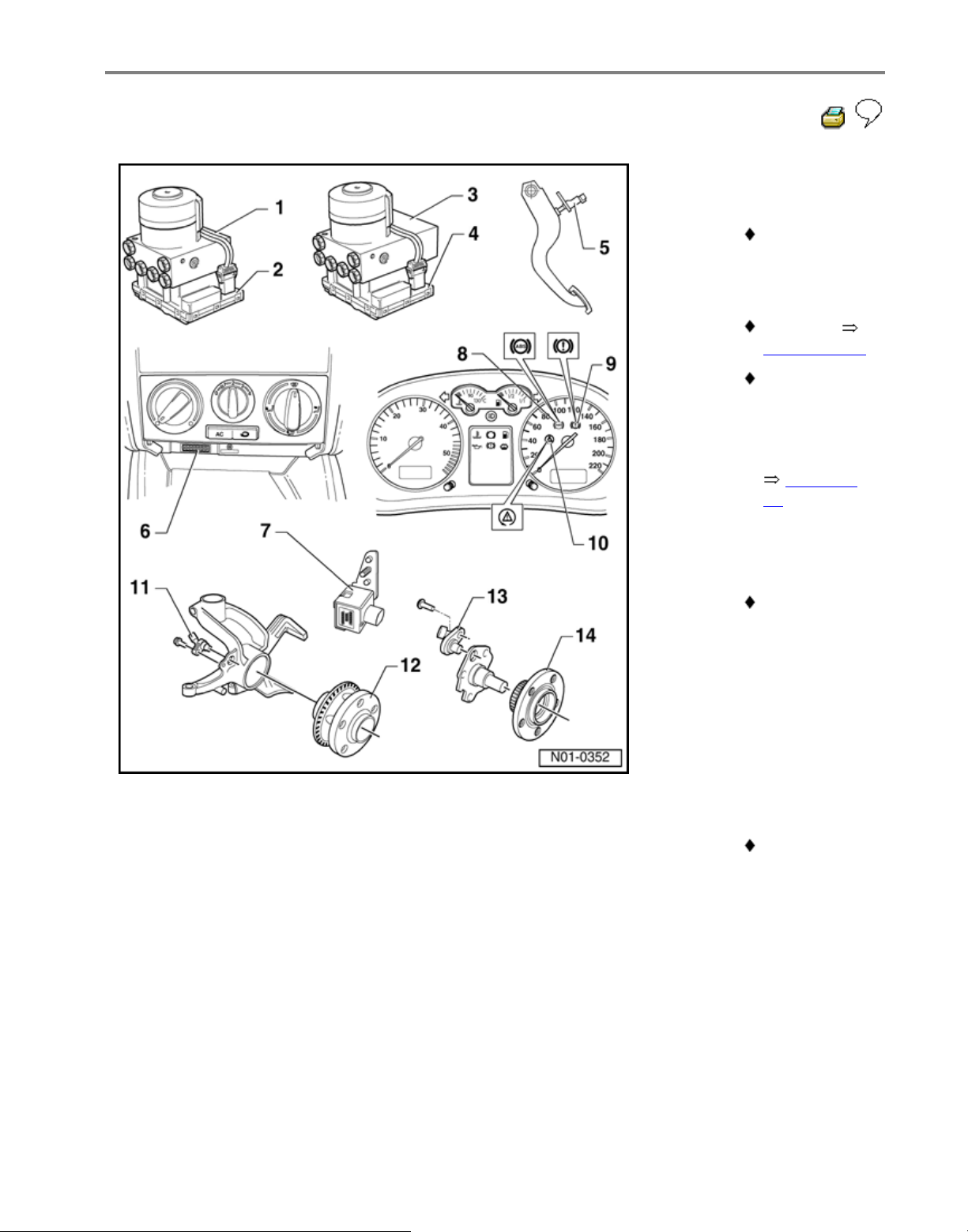
5 - Brake light
switch -F-
The brake
light switch is
open in the
rest position;
Adjusting
Page 01-131
Can be
checked via
read
measured
value block
Page 01
-
61
6 - Data Link
Connector
(DLC)
Installation
position: in
center
console
below
heating/air
conditioning
controls
7 - Longitudinal
acceleration
sensor -G251-
All-wheel
drive
vehicles with
Haldex
coupling only
Стр. 5 из 14Electrical/electronic components and locations
Page 15
01-14
8 - ABS warning
light -K47-
Location:
instrument
cluster
Function:
Page 01-17
9 - Warning light
for brake
system -K118-
Location:
instrument
cluster
Function:
Page 01-17
10 - ESP control
lamp -K155-
Location:
instrument
cluster
Стр. 6 из 14Electrical/electronic components and locations
Page 16
01-15
11 - Right/left
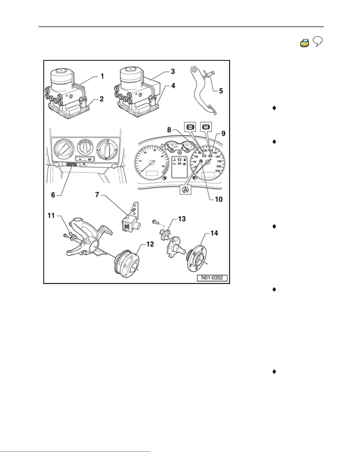
front ABS
wheel speed
sensor -G45-/G47-
Checked by
On Board
Diagnostic
(OBD)
Before
inserting the
sensor clean
the inner
surface of
the sensor
mounting
and coat with
lubricating
paste G 000
650
When
connecting
the speed
sensor wire
ensure it is
not twisted in
the wheel
housing
Bolt
tightening
torque - 10
Nm
12 - Wheel hub
with impulse
rotor for
right/left front
speed
sensors
Rotor and
speed
sensors for
front left and
right-hand
sides are
identical
Стр. 7 из 14Electrical/electronic components and locations
Page 17

Repair Manual,
Suspension, Wheels,
Steering, Repair
Group 40
Removing
and installing
Стр. 8 из 14Electrical/electronic components and locations
Page 18
01-16
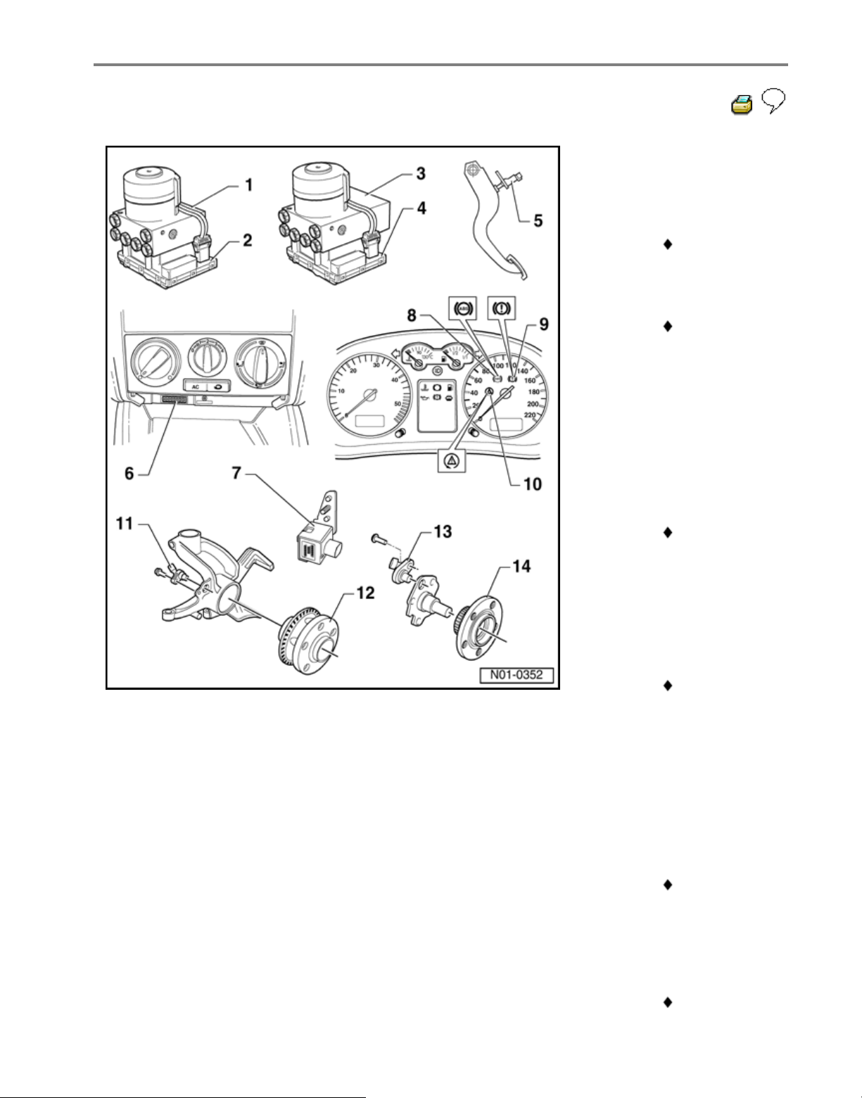
13 - Right/left rear
ABS wheel
speed sensor
-G44-/-G46-
Checked by
On Board
Diagnostic
(OBD)
Before
inserting the
sensor clean
the inner
surface of
the sensor
mounting
and coat with
lubricating
paste G 000
650
When
connecting
the speed
sensor wire
ensure it is
not twisted in
the wheel
housing
Bolt
tightening
torque - 10
Nm
14 - Wheel hub
with impulse
rotor for
right/left rear
speed
sensors
Rotor and
speed
sensors for
left and righthand sides
are identical
Removing
and installing
Стр. 9 из 14Electrical/electronic components and locations
Page 19

Repair Manual,
Suspension, Wheels,
Steering, Repair
Group 42
Стр. 10 из 14Electrical/electronic components and locations
Page 20
01-17
Diagnostic Trouble Codes (DTC)
displayed by warning lights -K14-, K47- and -K118-
Warning lights
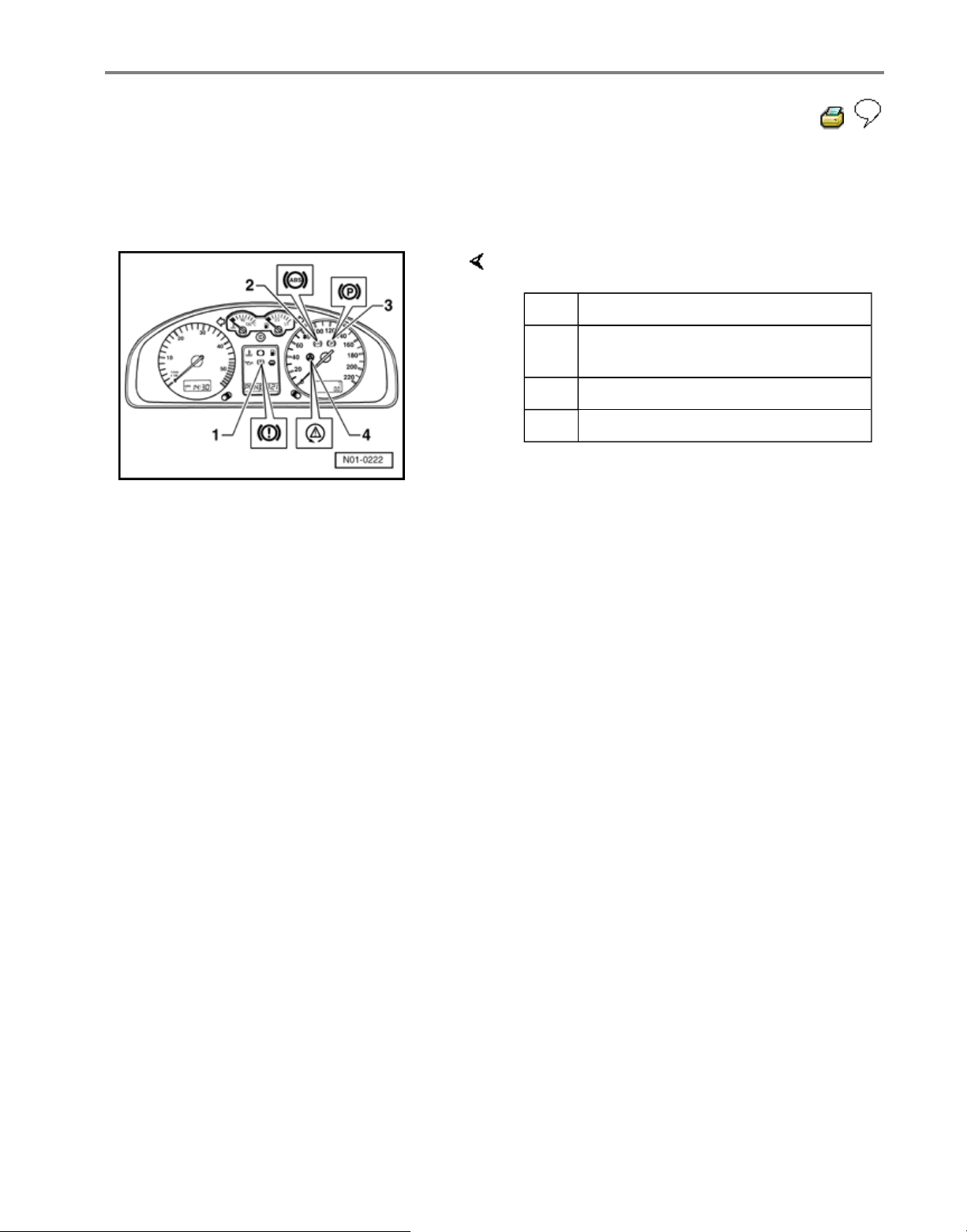
For vehicles with ABS/EDL/ASR and/or a
radio/navigation system, the warning
light for brake system -K118- is at
position -3-.
The function of the parking brake
warning light -K14- is then taken on by
the warning light for brake system K118-.
Item
Designation
1 Warning light for brake system -
K118-
2 ABS warning light -K47-
3 Parking brake indicator light -K14-
Стр. 11 из 14Electrical/electronic components and locations
Page 21
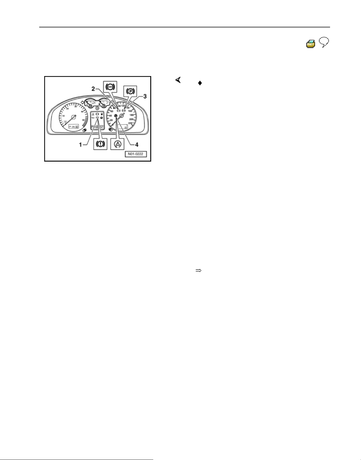
01-18
ABS warning light -K47-
Electrical Wiring Diagrams,
Troubleshooting & Component Locations
binder
If the ABS warning light -K47- (-2-) does
not go out after switching ignition on and
completion of test sequence then the
malfunction may be:
-a- Voltage supply is below 10 Volts
-b- There is a malfunction in the ABS
The anti-locking brake system remains
switched off with an ABS malfunction -b-,
but the brake system remains fully
operational.
-c- Since the last time the vehicle was
started there was a temporary speed
sensor malfunction.
In the case of a sensor malfunction -c-,
the ABS warning light -K47- will
extinguish after restarting the engine and
attaining a speed of above 20 km/h
(approx. 13 mph).
-d- The connection from instrument cluster
to ABS control module (w/EDL) -J104- is
interrupted.
-e- Instrument cluster is faulty.
Стр. 12 из 14Electrical/electronic components and locations
Page 22
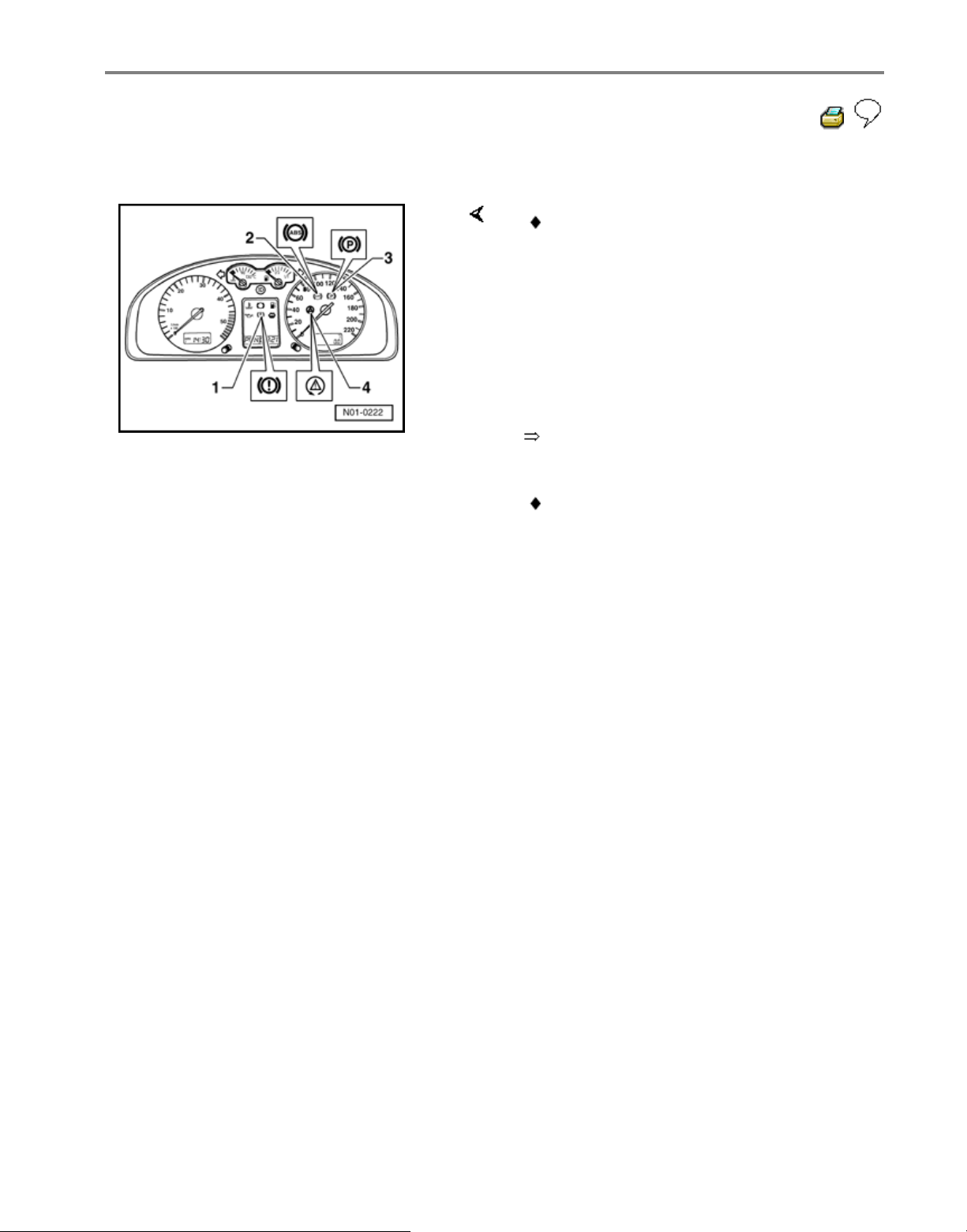
01-19
ABS warning lights -K47- and -K118-
Electrical Wiring Diagrams,
Troubleshooting & Component Locations
binder
WARNING!
After the ABS warning light -K47- and
warning light for brake system -K118have illuminated it is possible that the
rear wheels will lock-up earlier when
braking.
If the ABS warning light -K47- (-2-) goes
out but the warning light for brake
system -K118- (-1-) remains on and
three warning tones are audible then the
malfunction may be:
-a- The brake fluid level is too low.
-b- There is a malfunction in the activation
of the warning light for brake system K118-.
If the ABS warning light -K47- (-2-) and
the brake system warning light -K118- (1-) light up, the ABS system is faulty
and the EBD (Electronic Brake pressure
Distribution) is not functioning.
Стр. 13 из 14Electrical/electronic components and locations
Page 23
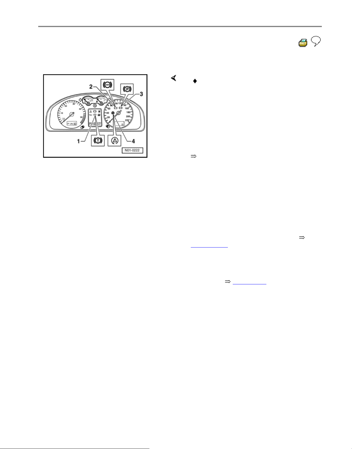
01-20
Parking brake indicator light -K14-
Electrical Wiring Diagrams,
Troubleshooting & Component Locations
binder
Vehicles with ABS/EDL
Malfunction: Vehicle has no EDL
function
For this complaint a possible cause may be
the brake light switch -F- is incorrectly
adjusted. Adjusting brake light switch
Page 01-131 .
Another possible cause may be the brake
light switch -F- is not functioning. The
function can be checked in Read measured
value block Page 01
-61 , display group
number 003.
If the parking brake indicator light -K14-
-3- does not go out after switching the
ignition on, the malfunction may be:
-a- The parking brake is applied.
-b- The parking brake warning light switch F9- for the parking brake indicator light K14- is faulty or incorrectly adjusted.
-c- There is a wire routing malfunction.
Стр. 14 из 14Electrical/electronic components and locations
Page 24
01-21
ABS ITT Mk 20 IE On Board
Diagnostic (OBD) program
All functions which could previously be
performed with V.A.G 1551 can also be
performed with the new tester VAS 5051.
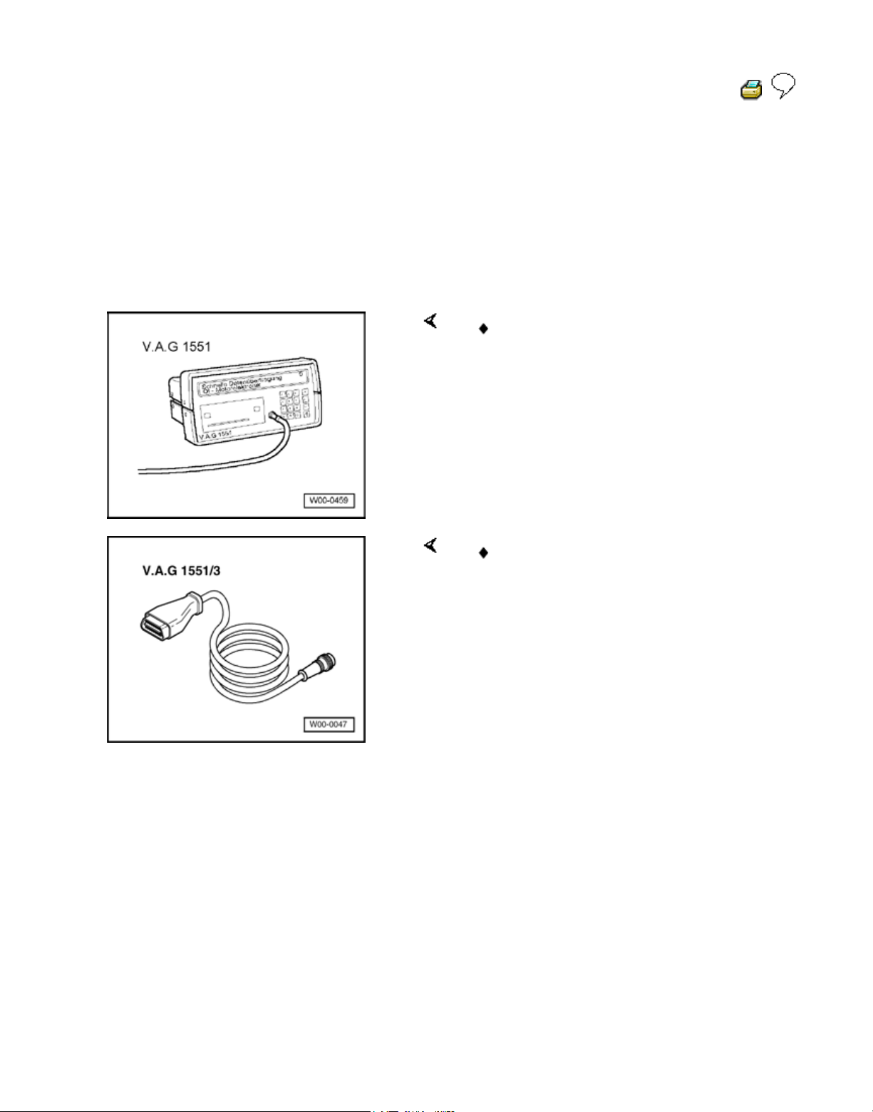
Special tools and equipment
V.A.G 1551 Scan Tool or V.A.G 1552
vehicle system tester.
V.A.G 1551/3 or 1551/3A Adapter cable
Стр. 1 из 81ABS ITT Mk 20 IE On Board Diagnostic (OBD) program
Page 25

01-22
Test requirements
The tires installed to all wheels must be of
the same (approved) size; tires inflated to
prescribed pressure.
Mechanical/hydraulic parts of the brake
system including brake light switch and
brake lights OK.
Hydraulic lines and connections not leaking
(visual check of hydraulic unit, brake
calipers, wheel cylinders, tandem master
brake cylinder).
Wheel bearings and wheel bearing play
OK.
ABS control module (w/EDL) -J104- is
correctly bolted to hydraulic unit -N55-.
Connector on ABS control module (w/EDL)
-J104- correctly plugged-in (retainer is
engaged).
Check contacts of ABS components for
damage and correct seating.
All fuses OK according to wiring diagram
(remove fuse from fuse holder to check).
Supply voltage OK (at least 10.0 V).
Стр. 2 из 81ABS ITT Mk 20 IE On Board Diagnostic (OBD) program
Page 26
01-23
V.A.G 1551 Scan Tool, connecting and
selecting function
Note:
All functions which could previously be
performed with V.A.G 1551 can also be
performed with the new tester VAS 5051.
The ABS function is switched off in the control
module during the On Board Diagnostic (OBD)
.
The Diagnostic Trouble Code (DTC) memory
can be erased after successful checking and
repair.
Connecting VAS 5051 Page 01-31 .
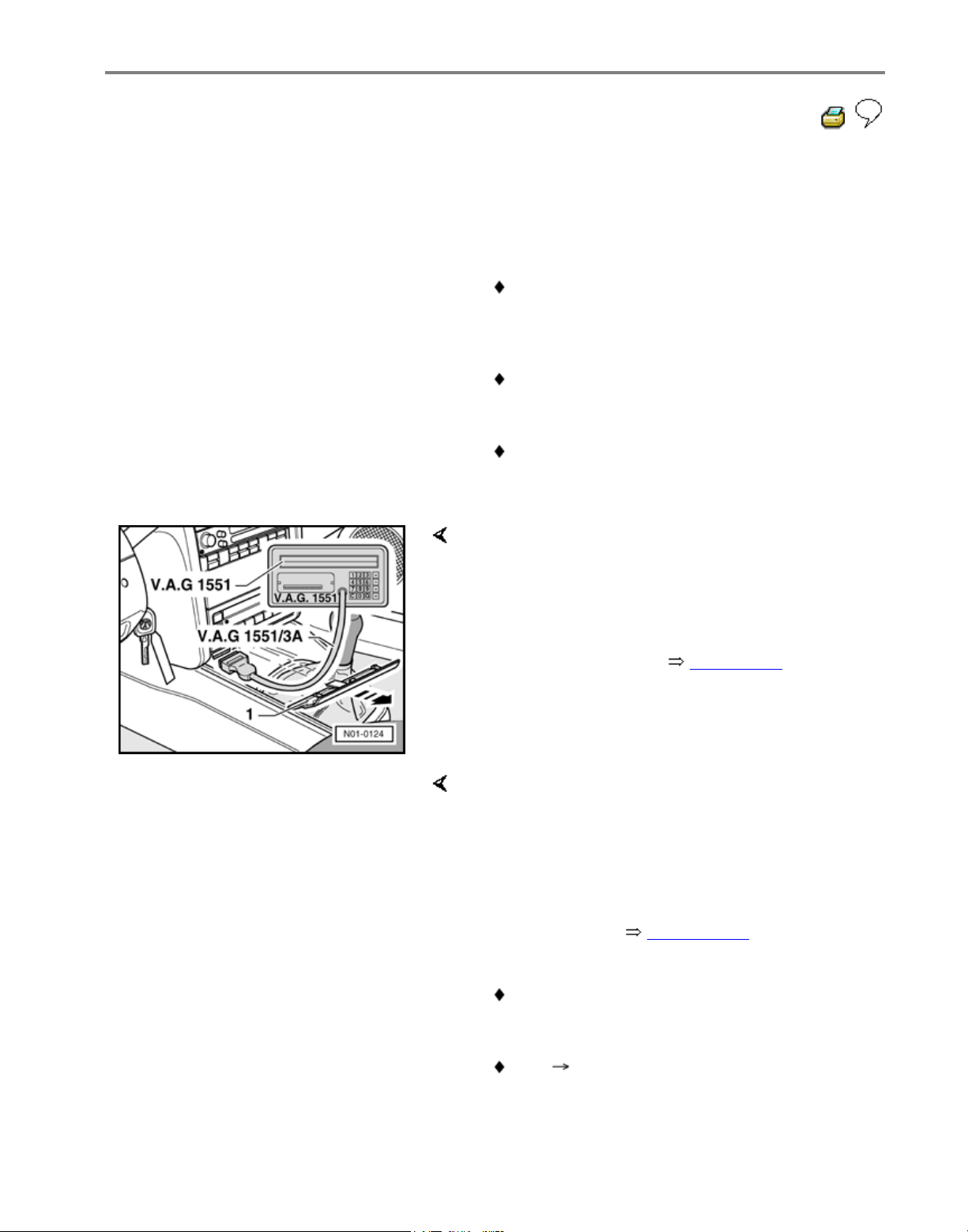
- Pull cover -1- off in direction of arrow.
- With ignition switched off connect V.A.G 1551
using cable V.A.G 1551/3(A) to Data Link
Connector
V
.A.G - On Board Diagnostic HELP
1 - Rapid data transfer1
)
2 - Blink code output1
)
Indicated on display
1)
Is displayed alternately
Note:
If there is no indication on display, check DLC,
Electrical checks Page 01-102 , test steps 14
and 15.
Depending on the program, additional operatin
g
information can be printed out by pressing the
HELP key of V.A.G 1551.
The key is used for moving forward within
the program.
Стр. 3 из 81ABS ITT Mk 20 IE On Board Diagnostic (OBD) program
Page 27

01-24
The PRINT key is used for switching on the
printer (warning lamp in key comes on).
- Switch ignition on.
- Switch on printer with Print key (indicator lamp in
key lights up).
- Press key -1- for "Rapid data transfer" operating
mode.
Rapid data transfer HELP
Enter address word XX
Indicated on display
- Press keys -0- and -3-; 03 inputs the address
word of the vehicle system to be tested "Brake
electronics".
Rapid data transfer Q
03 - Brake electronics
Indicated on display
- Confirm input with Q key.
1J0 907 379 D ABS 20 IE CAN 0001
Coding 03604 WSC XXXXX
Display shows e.g.
Displayed is:
e.g. (1J0 907 379 D)
Allocation of control module see Parts catalog
Electrical Wiring Diagrams, Troubleshooting &
Component Locations binder
The control module identification number.
System designation (ABS 20 IE)
Data BUS present. (CAN)
Стр. 4 из 81ABS ITT Mk 20 IE On Board Diagnostic (OBD) program
Page 28

01-25
Control module code (03604).
Coding control module Page 01-58
Workshop code
V.A.G 1551 Scan Tool operating
instructions
If the control module identification number
does not appear Summary of selectable
functions Page 01
-27
-
Press key.
Rapid data transfer HELP
Select function XX
Indicated on display (select function, e.g. 02
- Check DTC memory).
Rapid data transfer HELP
Control module does not answer!
Indicated on display
By pressing the HELP key, a list of possible
fault causes is printed out.
If "Control module does not answer!" again
appears:
- After eliminating possible causes of
malfunctions, enter the address word 03
for "Brake electronics" again and
confirm.
Rapid data transfer HELP
Control module does not answer!
Indicated on display
- Perform test steps 1, 2 and 3 Page
01-102 , Electrical check.
Rapid data transfer
No signal from control module!
malfunctions have occurred during checking
of control module identification (possibly
influenced from external sources?)
Стр. 5 из 81ABS ITT Mk 20 IE On Board Diagnostic (OBD) program
Page 29

01-26
- Check DLC as well as voltage supply and
Ground connection for ABS Control Module
(w/EDL) -J104-, Electrical check, Page 01-
102 .
- After repairing possible causes of malfunction,
again enter address word 03 for "Brake
electronics" and confirm with Q key.
Стр. 6 из 81ABS ITT Mk 20 IE On Board Diagnostic (OBD) program
Page 30
01-27
List of selectable functions
Page
00
-
Automatic test sequence Page
01-30
01
-
Check control module version
Connecting V.A.G 1551 Scan
Tool and selecting functions
Page
01-23
02
-
Check DTC memory Page
01-28
03
-
Output Diagnostic Test Mode Page
01-74
04
-
Initiate basic setting Page
01-91
05
-
Erase DTC memory Page
01-56
06
-
End output Page
01-56
07
-
Code control module Page
01-58
08
-
Read measured value block Page
01-61
Стр. 7 из 81ABS ITT Mk 20 IE On Board Diagnostic (OBD) program
Page 31

01-28
Diagnostic Trouble Code (DTC),
memory
All functions which could previously be
performed with V.A.G 1551 can also be
performed with the new tester VAS 5051.
Rapid data transfer HELP
Select function XX
Indicated on display:
- Press keys -0- and -2-; 02 enters the
"Check DTC memory" function.
Rapid data transfer Q
02 - Check DTC memor
y
Indicated on display
- Confirm entry with Q key.
X DTCs recognised!
The number of stored DTCs or "No DTCs
recognized" appears in the display.
-
Press key.
The stored DTCs are displayed and
printed out one after the other.
- With DTC information print-out eliminate
malfunctions according to DTC table,
Page 01-35 .
As with "No DTC recognized", the
program returns to the start position after
pressing the key:
Rapid data transfer HELP
Select function XX
Indicated on display
- End output (Function 06) Page 01
-56 .
Стр. 8 из 81ABS ITT Mk 20 IE On Board Diagnostic (OBD) program
Page 32

01-29
- Switch off ignition and disconnect tester at
DLC.
Work sequence if a DTC has been detected:
1. Repair according to DTC table, Page 01-
35
2. Check DTC memory (Function 02)
3. Erase DTC memory (Function 05)
4. End output (Function 06)
5. Perform a test drive
6. Check DTC memory again
Стр. 9 из 81ABS ITT Mk 20 IE On Board Diagnostic (OBD) program
Page 33

01-30
Automatic test sequence
The automatic test sequence checks all the
Diagnostic Trouble Code (DTC) memories
of the control modules.
- Switch ignition on.
V
.A.G - On Board Diagnostic HELP
1 - Rapid data transfer1
)
2 - Blink code output1
)
Indicated on display
1)
Is displayed alternately
- Press key -1- for "Rapid data transfer"
operating mode.
- Switch on printer with the Print key
(indicator lamp in key lights up).
Rapid data transfer HELP
Select function XX
Indicated on display
- Press key -0- twice; 00 enters "Automatic
test sequence" function.
- Confirm entry with Q key.
1J0 907 379 D ABS 20 IE CAN0001
Coding 03604 WSC XXXXX
The V.A.G 1551 Scan Tool display will
show the control module identification, e.g.:
Thereafter all control module
identifications with eventual DTC
memory entries are displayed
Стр. 10 из 81ABS ITT Mk 20 IE On Board Diagnostic (OBD) program
Page 34
01-31
Vehicle Diagnosis, Testing and
Information System VAS 5051,
connecting and selecting ABS
control module
All functions which could previously be
performed with V.A.G 1551 can also be
performed with the new tester VAS 5051 in
the operating mode "Vehicle On Board
Diagnostic":
Operating instructions for Vehicle
Diagnosis, Testing and Information System
VAS 5051.
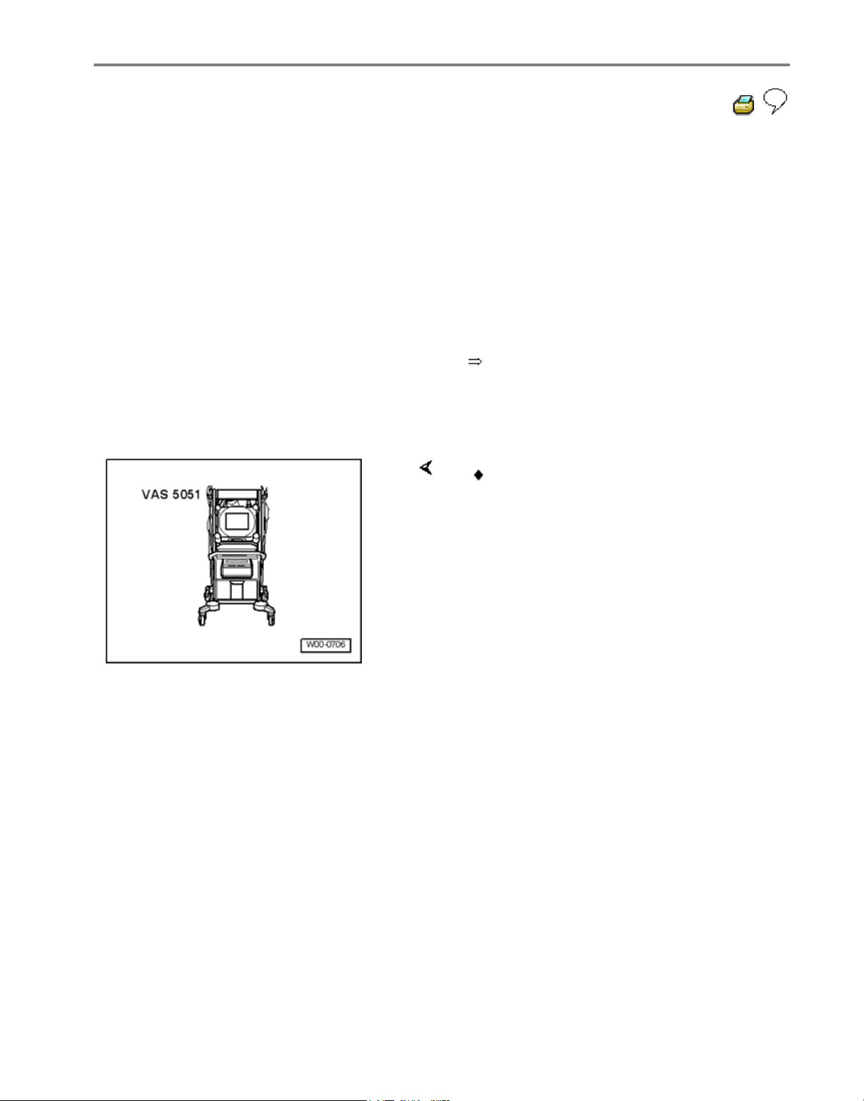
Special tools and equipment
VAS 5051 Vehicle Diagnosis, Testing
and Information System
Стр. 11 из 81ABS ITT Mk 20 IE On Board Diagnostic (OBD) program
Page 35
01-32
Note:
The ABS function is switched off in the control
module during the On Board Diagnostic.
The DTC memory can be erased after
successful checking and repair.
Note:
Operating instructions for Vehicle Diagnosis,
Testing and Information System VAS 5051.
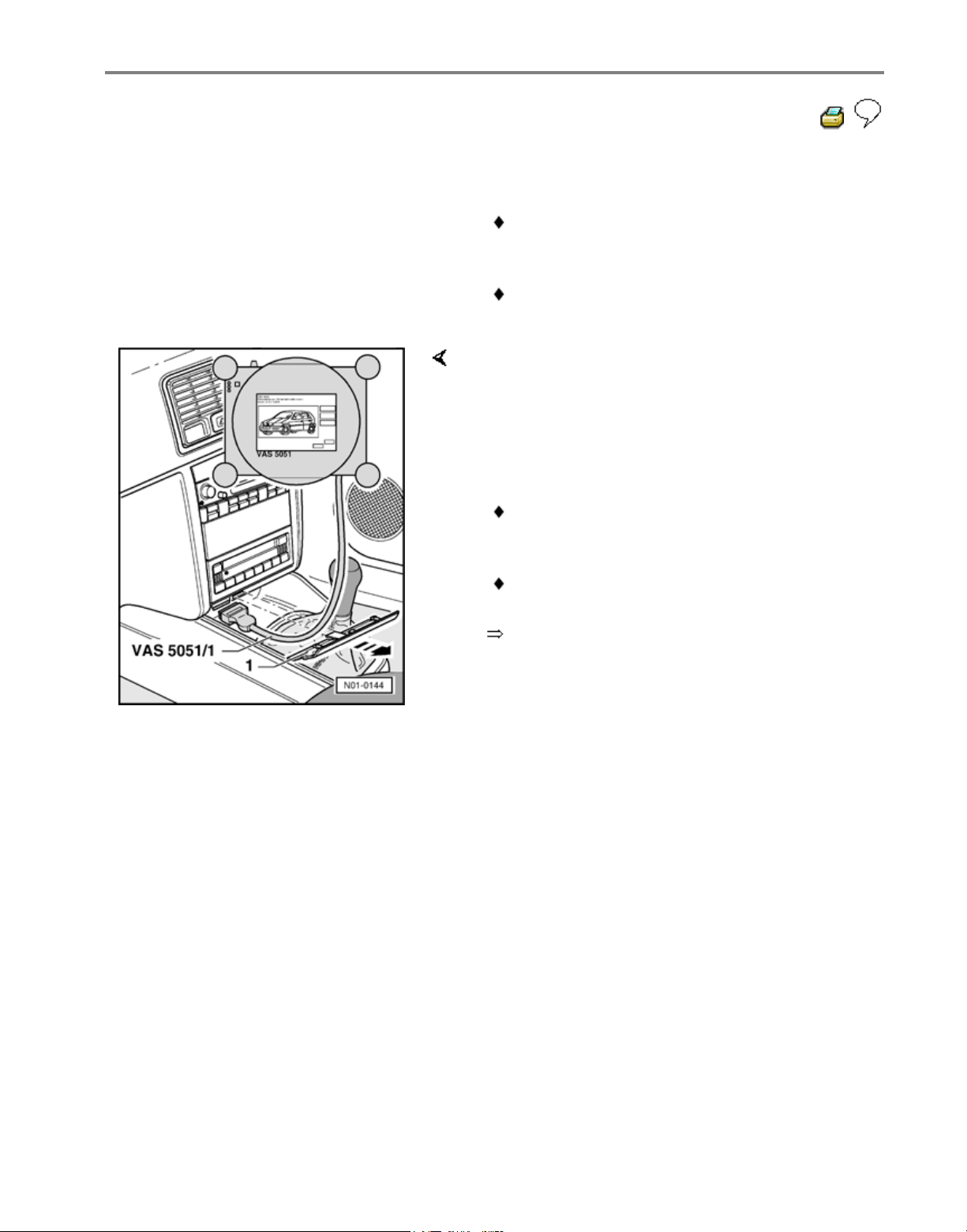
- Pull cover -1- off in direction of -arrow-.
- With ignition switched off, connect tester VAS
5051 to diagnosis connection using diagnosis
cable VAS 5051/1 or VAS 5051/3.
In the functions 04 - Basic setting/08 - Read
Measured value block, the display zones will b
e
listed from top to bottom.
If the display does not indicate as described in
the work sequence:
Стр. 12 из 81ABS ITT Mk 20 IE On Board Diagnostic (OBD) program
Page 36
01-33
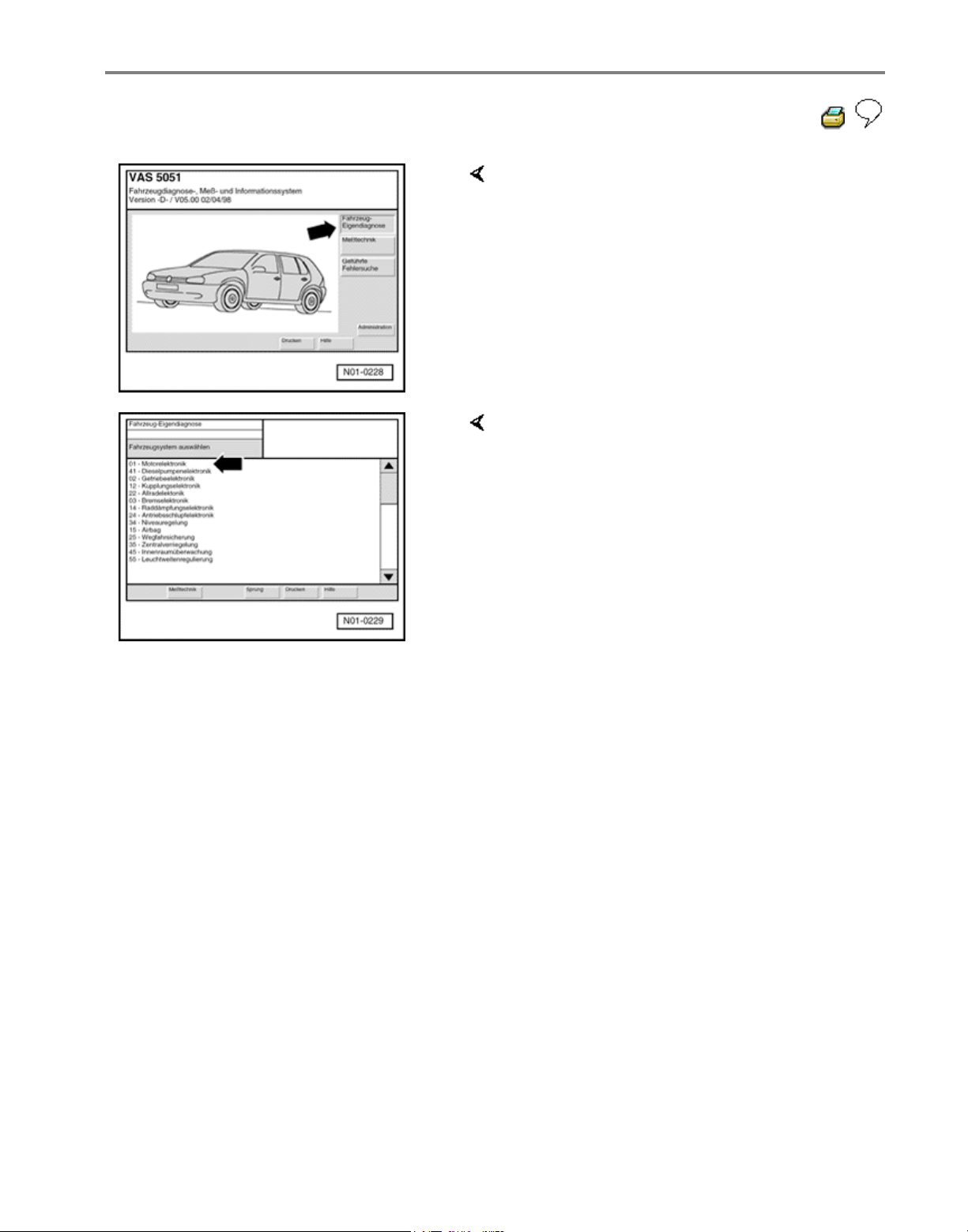
Indicated on display
Select operating mode:
- Press button on display for "Vehicle On
Board Diagnostic" -arrow-.
Indicated on display
Select vehicle system:
- Press "03 - Brake electronics" on display
-arrow-.
Стр. 13 из 81ABS ITT Mk 20 IE On Board Diagnostic (OBD) program
Page 37
01-34
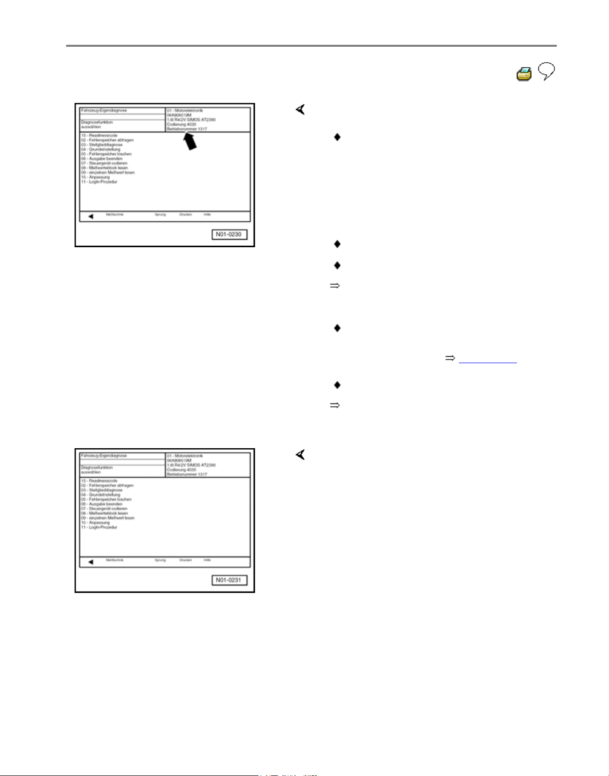
Displayed is
e.g. (1J0 907 379 D)
Allocation of control module see Parts
catalog
Electrical Wiring Diagrams,
Troubleshooting & Component Locations
binder
Coding control module Page 01-58
Operating instructions for Vehicle
Diagnosis, Testing and Information System
VAS 5051.
The control module identification
number.
System designation (ABS 20 IE)
Data BUS present. (CAN)
Control module code (03504).
Workshop code
Indicated on display
Select diagnostic function:
At this point all diagnostic functions are
available.
For further measures see repair
procedures.
Стр. 14 из 81ABS ITT Mk 20 IE On Board Diagnostic (OBD) program
Page 38

01-35
Diagnostic Trouble Code (DTC) table
Note on DTC table:
When beginning OBD of the vehicle control modules, always start with function "Automatic
test sequence" by pressing keys 0 and 0 because the control modules are interconnected
with a data bus wire. This checks the DTC memories of the control modules in the vehicle.
All the possible DTCs which can be recognized by the ABS control module -J104- and
printed-out on V.A.G 1551 or VAS 5051, are listed on the following pages according to the
5-digit DTC.
DTC appears (in the "Rapid data transfer" mode) only on the print-out.
Example:
DTC P code DTC type code
5-digit 5-digit 3-digit
18256 P1848 035
The 5-digit P code which may appear next to the DTC, is for use with the On Board
Diagnostic (OBD) II and may be disregarded.
The 3-digit DTC type code is a data code and may be disregarded, but the DTC type text is
of use.
Before replacing components indicated as being faulty, check all the appropriate
connectors, wiring and Ground connections using the wiring diagram
Electrical Wiring Diagrams, Troubleshooting & Component Locations binder
On completion of repairs always check the DTC memory with V.A.G 1551 Scan Too. or the
tester VAS 5051 and erase.
Carry out road test exceeding 20 km/h (13 mph).
After the road test check DTC memory again.
Стр. 15 из 81ABS ITT Mk 20 IE On Board Diagnostic (OBD) program
Page 39
01-36
V.A.G 1551
print-out
Possible cause
Repair
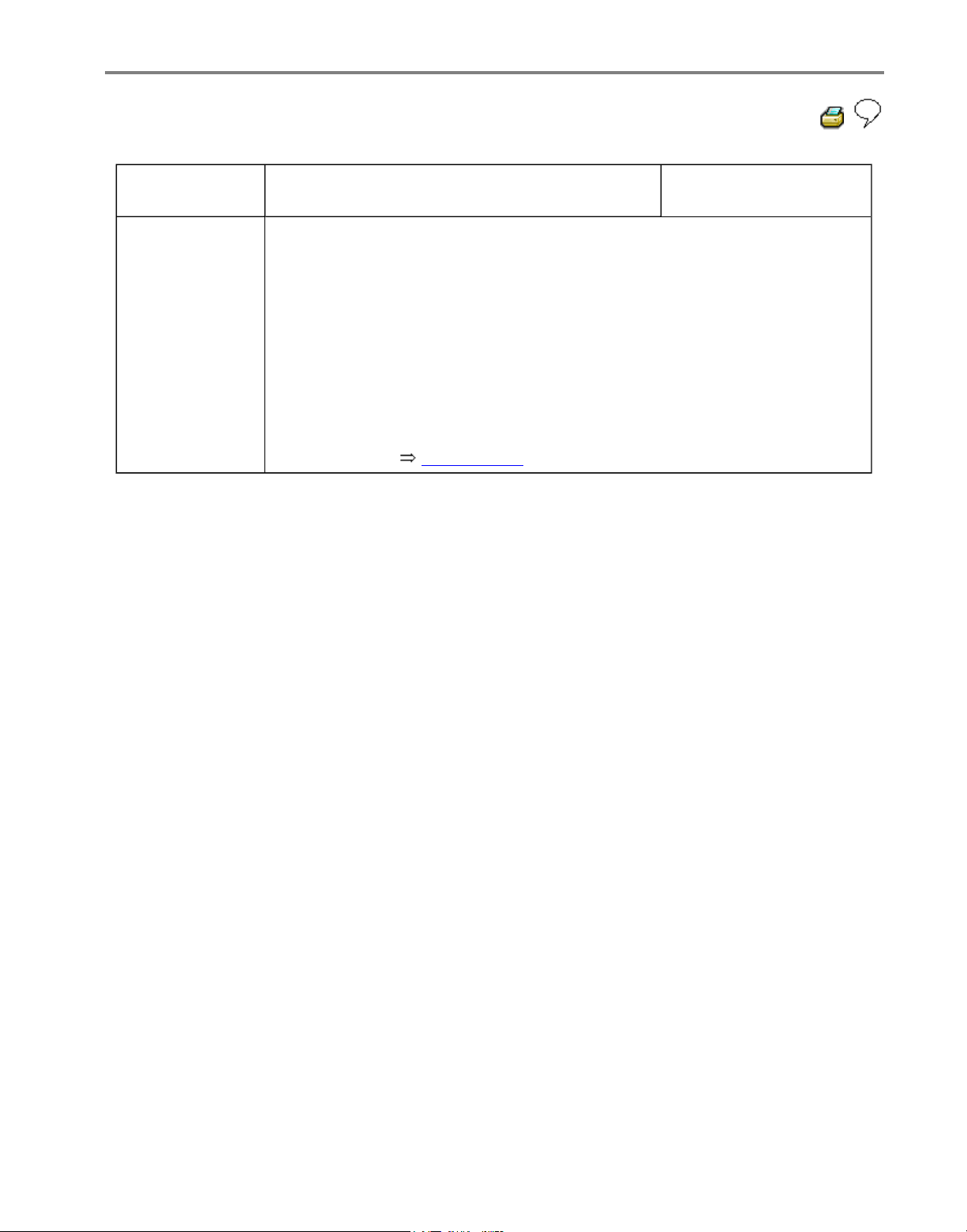
No DTC
recognized
If "No DTC recognized" appears after carrying out repairs, On Board
Diagnostic (OBD) is ended.
If, despite "No DTC recognized" appearing in the display, the ABS system
does not function properly, then proceed as follows:
1. Carry out road test exceeding 20 km/h (13 mph),
2. Again check DTC memory, if there is still no DTC stored,
3. Continue troubleshooting without OBD and work through the complete
Electrical check Page 01-102 .
Стр. 16 из 81ABS ITT Mk 20 IE On Board Diagnostic (OBD) program
Page 40
01-37
V.A.G 1551
print-out
Possible cause
Repair
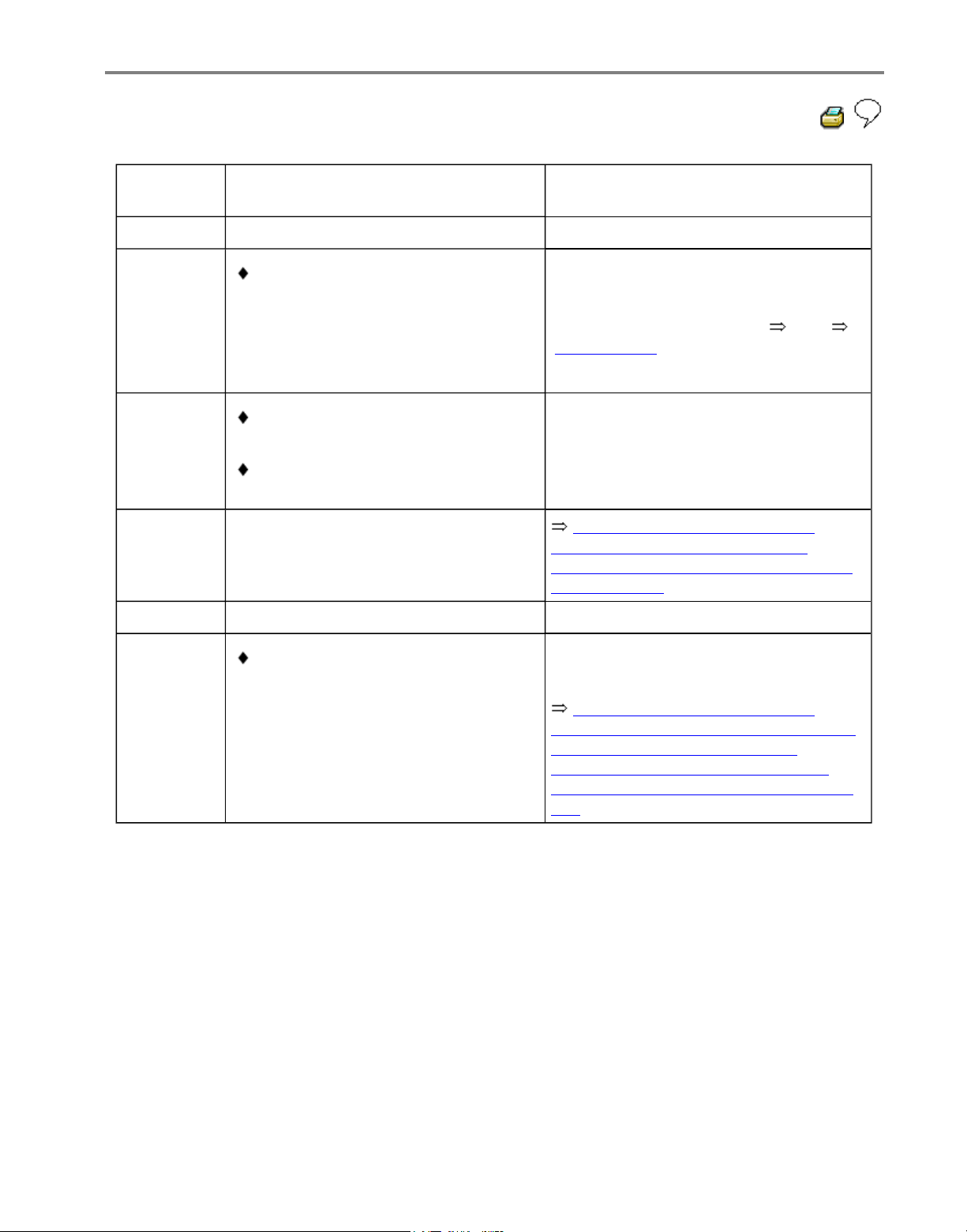
00283
Left front
ABS wheel
speed
sensor G47-
Open circuit, short to positive or
Ground, or loose contact in
connections between left front ABS
wheel speed sensor -G47- and
ABS Control Module (w/EDL) J104-
- Check wiring and connections using
wiring diagram
- Perform electrical checks from
Page 01-102
Damaged rotor or left front ABS
wheel speed sensor -G47
Left front ABS wheel speed sensor
windings -G47- faulty
- Check left front ABS wheel speed
sensor -G47- and rotor for damage
- Replace rotor/speed sensor -G47-
Repair Manual, Brake System,
Repair Group 45; Removing and
installing parts of ABS system on front
and rear axles
If the malfunction occurs again:
ABS Control Module (w/EDL) J104- faulty
Repair Manual, Brake System,
Repair Group 45; Hydraulic unit, brake
booster/brake master cylinder Assembly overview; Removing and
installing control module and hydraulic
unit
- Replace ABS Control Module
(w/EDL) -J104-
Стр. 17 из 81ABS ITT Mk 20 IE On Board Diagnostic (OBD) program
Volkswagen Technical Site: http://volkswagen.msk.ru http://vwts.info http://vwts.ru
огромный архив документации по автомобилям Volkswagen, Skoda, Seat, Audi
Page 41
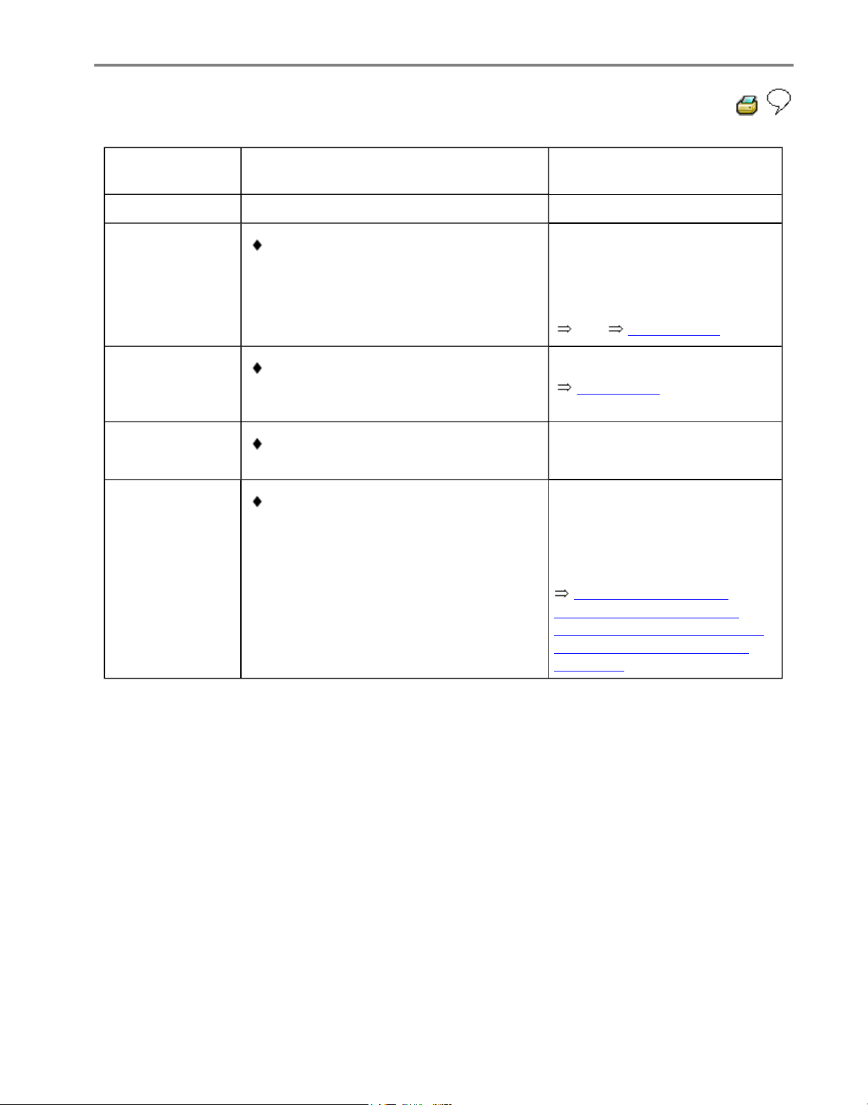
01-38
V.A.G 1551
print-out
Possible cause
Repair
00283
Left front ABS
wheel speed
sensor -G47-
Signal outside
tolerances1)
Open circuit, short to positive or
Ground, or loose contact in
connections between left front ABS
wheel speed sensor -G47- and ABS
Control Module (w/EDL) -J104-
- Check wiring and
connections using wiring
diagram
- Perform electrical checks
from Page 01-102
Electrical interference from other
sources (high frequency radiation e.g.
non-insulated ignition cable)
- Read measured value block
Page 01-61 Display group
number 001
Damaged rotor or left front ABS wheel
speed sensor -G47-
Excessive air gap between left front
ABS wheel speed sensor-G47- and
rotor (signal not OK.)
Repair Manual, Brake
System, Repair Group 45;
Removing and installing parts
of ABS system on front and
rear axles
- Check left front ABS wheel
speed sensor -G47- and rotor
for damage
- Replace rotor/speed sensor
1)
Type of DTC, this DTC is only recognized above 20 km/h (13 mph) (carry out test drive).
Стр. 18 из 81ABS ITT Mk 20 IE On Board Diagnostic (OBD) program
Page 42
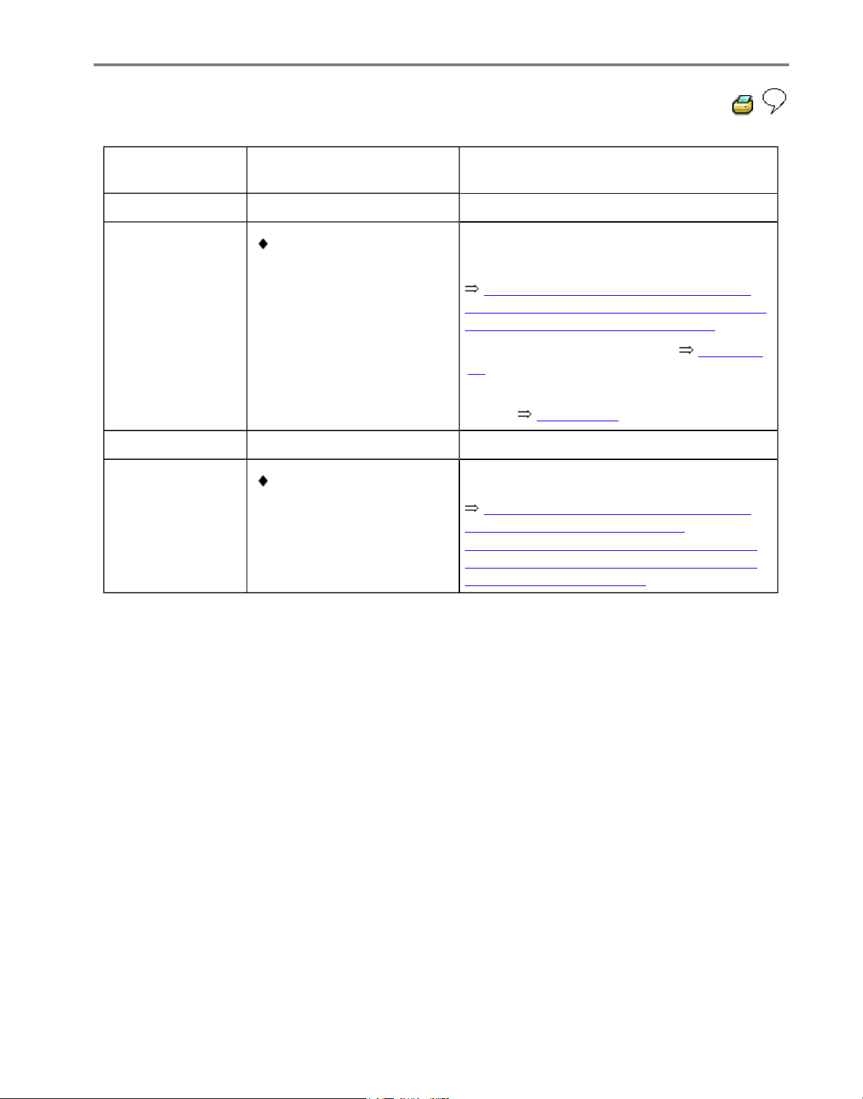
01-39
V.A.G 1551 printout
Possible cause
Repair
00283
Left front ABS
wheel speed
sensor -G47-
Mechanical
malfunction1)
Excessive air gap
between left front ABS
wheel speed sensor G47- and rotor (signal
not OK.)
Repair Manual, Brake System, Repair
Group 45; Removing and installing parts of
ABS system on front and rear axles
- Check installation of left front ABS wheel
speed sensor -G47- and rotor
- Read measured value block Page 01-
61 Display group number 002
- Perform output Diagnostic Test Mode
(DTM) Page 01-74
If the malfunction occurs again:
Outlet valve in ABS
hydraulic unit -N55faulty
Repair Manual, Brake System, Repair
Group 45; Hydraulic unit, brake
booster/brake master cylinder - Assembly
overview; Removing and installing control
module and hydraulic unit
- Replace ABS hydraulic unit -N55-
1)
Type of DTC, this DTC is only recognized above 20 km/h (13 mph) (carry out test drive).
Стр. 19 из 81ABS ITT Mk 20 IE On Board Diagnostic (OBD) program
Page 43
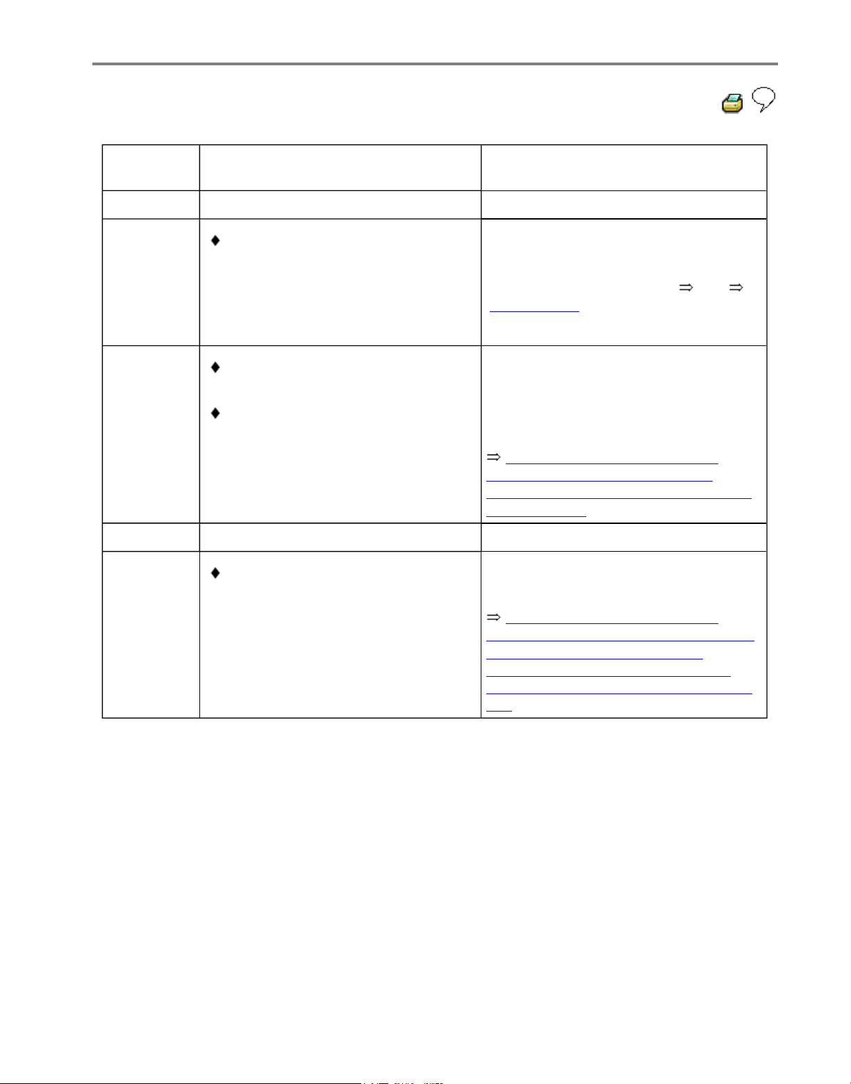
01-40
V.A.G 1551
print-out
Possible cause
Repair
00285
Right front
ABS wheel
speed
sensor G45-
Open circuit, short to positive or
Ground, or loose contact in
connections between right front
ABS wheel speed sensor -G45and ABS Control Module (w/EDL) J104-
- Check wiring and connections using
wiring diagram
- Perform electrical checks from
Page 01-102
Damaged rotor or speed sensor G45
Speed sensor windings -G45faulty
Repair Manual, Brake System,
Repair Group 45; Removing and
installing parts of ABS system on front
and rear axles
- Check right front ABS wheel speed
sensor -G45- and rotor for damage
- Replace rotor/right front ABS wheel
speed sensor -G45-
If the malfunction occurs again:
ABS Control Module (w/EDL) J104- faulty
Repair Manual, Brake System,
Repair Group 45; Hydraulic unit, brake
booster/brake master cylinder Assembly overview; Removing and
installing control module and hydraulic
unit
- Replace ABS Control Module
(w/EDL) -J104-
Стр. 20 из 81ABS ITT Mk 20 IE On Board Diagnostic (OBD) program
Page 44
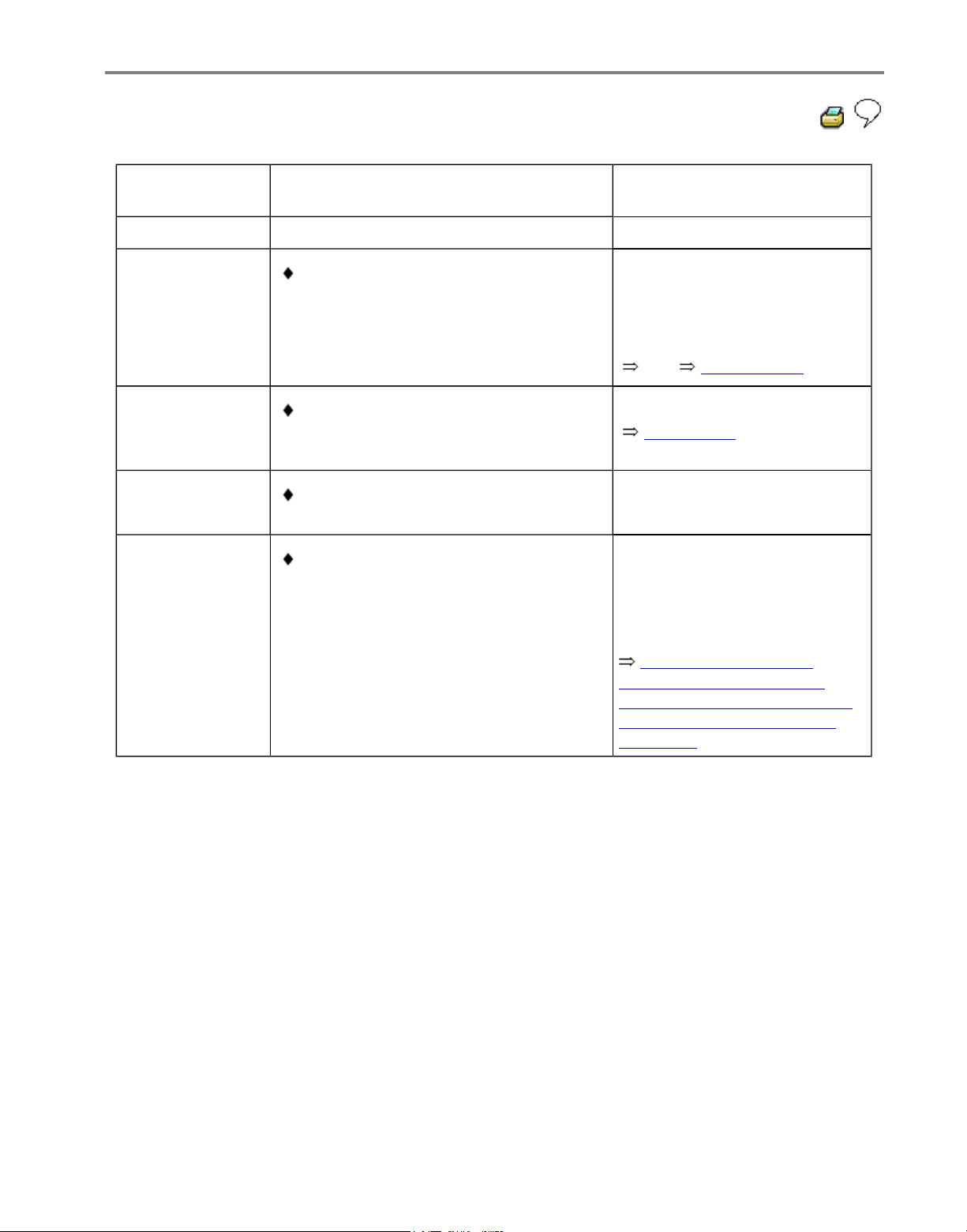
01-41
V.A.G 1551
print-out
Possible cause
Repair
00285
Right front ABS
wheel speed
sensor -G45-
Signal outside
tolerances1)
Open circuit, short to positive or
Ground, or loose contact in
connections between right front ABS
wheel speed sensor -G45- and ABS
Control Module (w/EDL) -J104-
- Check wiring and
connections using wiring
diagram
- Perform electrical checks
from Page 01-102
Electrical interference from other
sources (high frequency radiation e.g.
non-insulated ignition cable)
- Read measured value block
Page 01-61 Display group
number 001
Damaged rotor or right front ABS
wheel speed sensor -G45-
Excessive air gap between right front
ABS wheel speed sensor-G45- and
rotor (signal not OK)
Repair Manual, Brake
System, Repair Group 45;
Removing and installing parts
of ABS system on front and
rear axles
- Check right front ABS wheel
speed sensor -G45- and rotor
for damage
- Replace rotor/speed sensor
1)
Type of DTC, this DTC is only recognized above 20 km/h (13 mph) (carry out test drive).
Стр. 21 из 81ABS ITT Mk 20 IE On Board Diagnostic (OBD) program
Page 45
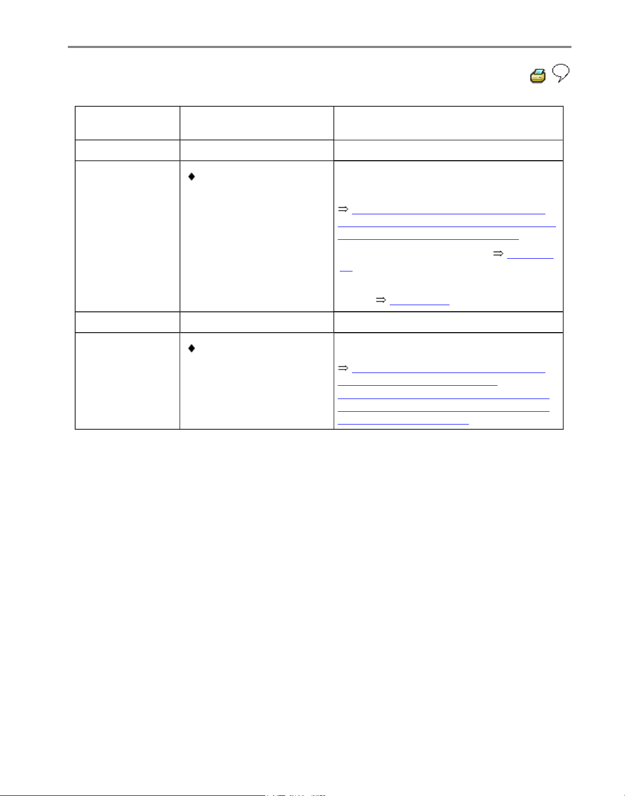
01-42
V.A.G 1551 printout
Possible cause
Repair
00285
Right front ABS
wheel speed
sensor -G45-
Mechanical
malfunction1)
Excessive air gap
between right front ABS
wheel speed sensorG45- and rotor (signal
not OK.)
Repair Manual, Brake System, Repair
Group 45; Removing and installing parts of
ABS system on front and rear axles
- Check installation of right front ABS
wheel speed sensor -G45- and rotor
- Read measured value block Page 01-
61 Display group number 002
- Perform output Diagnostic Test Mode
(DTM) Page 01-74
If the malfunction occurs again:
Outlet valve in ABS
hydraulic unit -N55faulty
Repair Manual, Brake System, Repair
Group 45; Hydraulic unit, brake
booster/brake master cylinder - Assembly
overview; Removing and installing control
module and hydraulic unit
- Replace ABS hydraulic unit -N55-
1)
Type of DTC, this DTC is only recognized above 20 km/h (13 mph) (carry out test drive).
Стр. 22 из 81ABS ITT Mk 20 IE On Board Diagnostic (OBD) program
Page 46
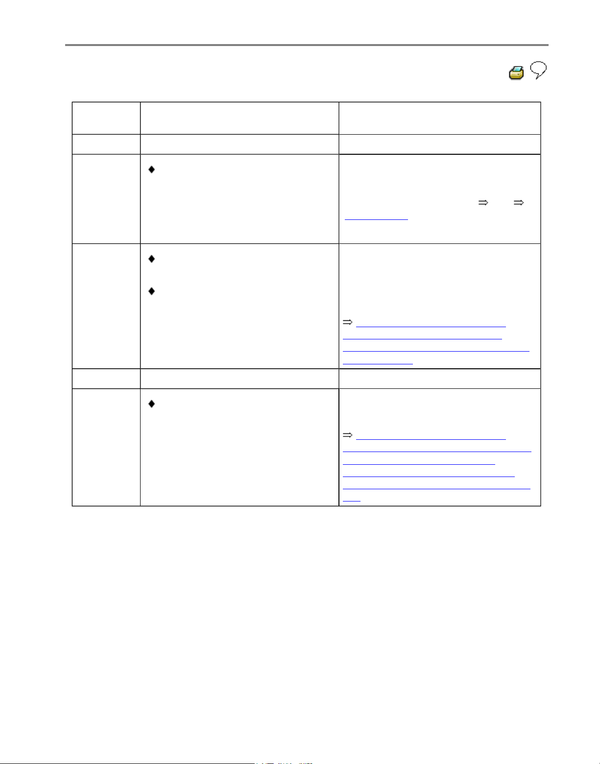
01-43
V.A.G 1551
print-out
Possible cause
Repair
00287
Right rear
ABS wheel
speed
sensor G44-
Open circuit, short to positive or
Ground, or loose contact in
connections between right rear
ABS wheel speed sensor -G44and ABS Control Module (w/EDL) J104-
- Check wiring and connections using
wiring diagram
- Perform electrical checks from
Page 01-102
Damaged rotor or right rear ABS
wheel speed sensor -G44-
Right rear ABS wheel speed
sensor windings -G44- faulty
Repair Manual, Brake System,
Repair Group 45; Removing and
installing parts of ABS system on front
and rear axles
- Check right rear ABS wheel speed
sensor -G44- and rotor for damage
- Replace rotor/right rear ABS wheel
speed sensor -G44-
If the malfunction occurs again:
ABS Control Module (w/EDL) J104- faulty
Repair Manual, Brake System,
Repair Group 45; Hydraulic unit, brake
booster/brake master cylinder Assembly overview; Removing and
installing control module and hydraulic
unit
- Replace ABS Control Module
(w/EDL) -J104-
Стр. 23 из 81ABS ITT Mk 20 IE On Board Diagnostic (OBD) program
Page 47
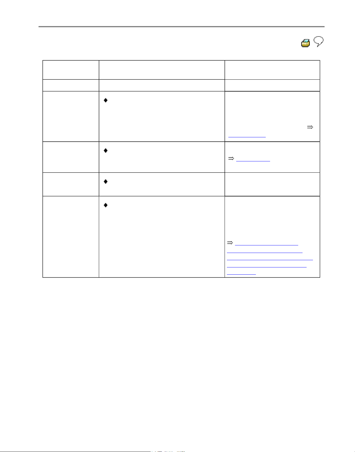
01-44
V.A.G 1551
print-out
Possible cause
Repair
00287
Right rear ABS
wheel speed
sensor -G44-
Signal outside
tolerances1)
Open circuit, short to positive or
Ground, or loose contact in
connections between right rear ABS
wheel speed sensor -G44- and ABS
Control Module (w/EDL) -J104-
- Check wiring and
connections using wiring
diagram
- Perform electrical checks
Page 01-102
Electrical interference from other
sources (high frequency radiation e.g.
non-insulated ignition cable)
- Read measured value block
Page 01-61 Display group
number 001
Damaged rotor or right rear ABS
wheel speed sensor -G44-
Excessive air gap between right rear
ABS wheel speed sensor -G44- and
rotor (signal not OK.)
Repair Manual, Brake
System, Repair Group 45;
Removing and installing parts
of ABS system on front and
rear axles
- Check right rear ABS wheel
speed sensor -G44- and rotor
for damage
- Replace rotor/speed sensor
1)
Type of DTC, this DTC is only recognized above 20 km/h (13 mph) (carry out test drive).
Стр. 24 из 81ABS ITT Mk 20 IE On Board Diagnostic (OBD) program
Page 48
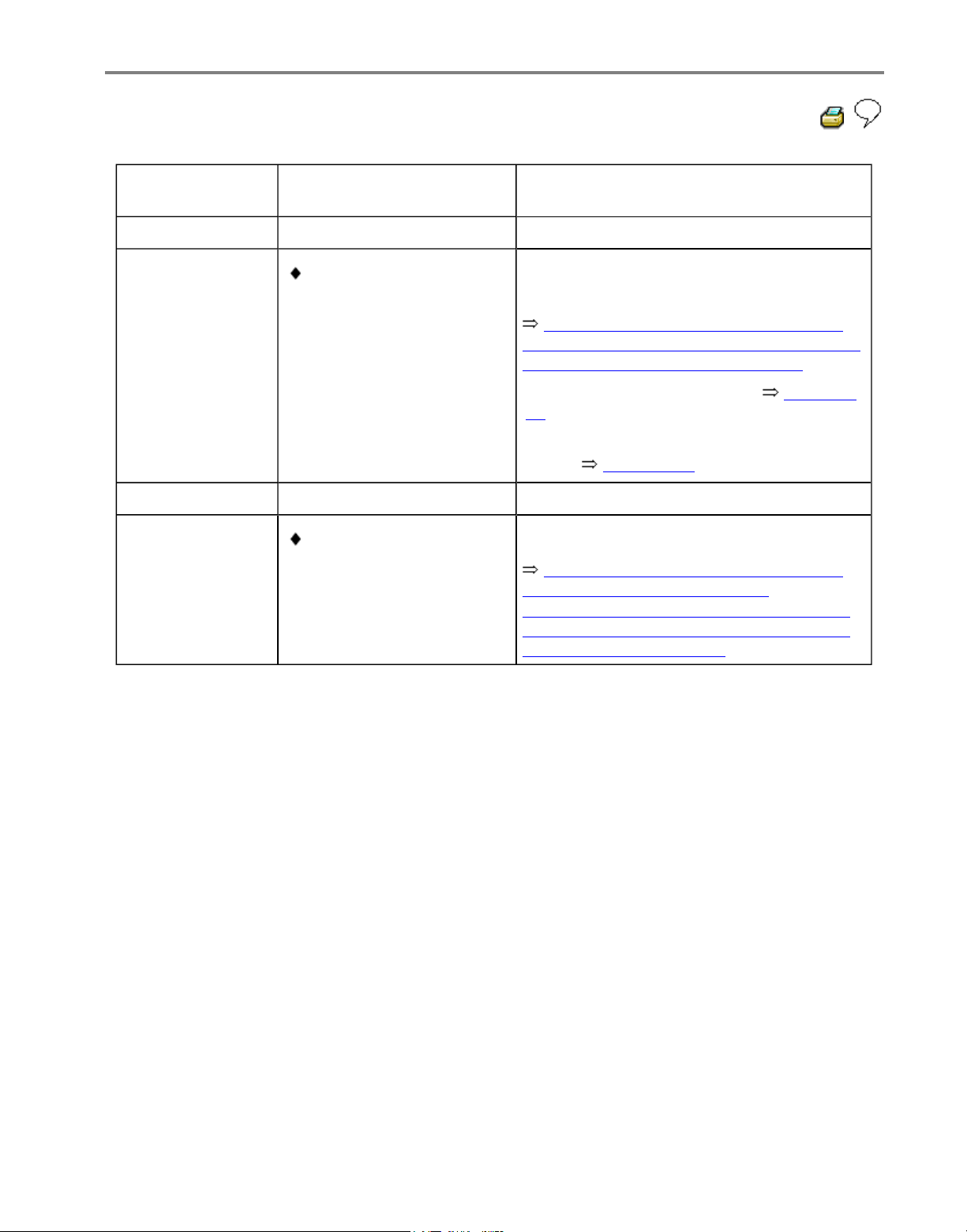
01-45
V.A.G 1551 printout
Possible cause
Repair
00287
Right rear ABS
wheel speed
sensor -G44-
Mechanical
malfunction1)
Excessive air gap
between right rear ABS
wheel speed sensor G44- and rotor (signal
not OK.)
Repair Manual, Brake System, Repair
Group 45; Removing and installing parts of
ABS system on front and rear axles
- Check installation of right rear ABS
wheel speed sensor -G44- and rotor
- Read measured value block Page 01-
61 Display group number 002
- Perform output Diagnostic Test Mode
(DTM) Page 01-74
If the malfunction occurs again:
Outlet valve in ABS
hydraulic unit -N55faulty
Repair Manual, Brake System, Repair
Group 45; Hydraulic unit, brake
booster/brake master cylinder - Assembly
overview; Removing and installing control
module and hydraulic unit
- Replace ABS hydraulic unit -N55-
1)
Type of DTC, this DTC is only recognized above 20 km/h (13 mph) (carry out test drive).
Стр. 25 из 81ABS ITT Mk 20 IE On Board Diagnostic (OBD) program
Page 49
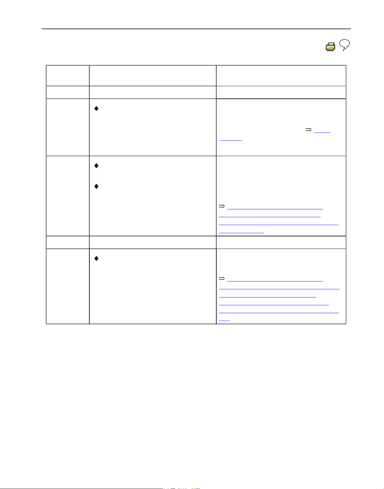
01-46
V.A.G 1551
print-out
Possible cause
Repair
00290
Left rear
ABS wheel
speed
sensor G46-
Open circuit, short to positive or
Ground, or loose contact in
connections between left rear ABS
wheel speed sensor -G46- and
ABS Control Module (w/EDL) J104-
- Check wiring and connections using
wiring diagram
- Perform electrical checks Page
01-102
Left rear ABS wheel speed sensor
windings -G46- faulty
Damaged rotor or left rear ABS
wheel speed sensor -G46-
Repair Manual, Brake System,
Repair Group 45; Removing and
installing parts of ABS system on front
and rear axles
- Check left rear ABS wheel speed
sensor -G46- and rotor for damage
- Replace rotor/left rear ABS wheel
speed sensor -G46-
If the malfunction occurs again:
ABS Control Module (w/EDL) J104- faulty
Repair Manual, Brake System,
Repair Group 45; Hydraulic unit, brake
booster/brake master cylinder Assembly overview; Removing and
installing control module and hydraulic
unit
- Replace ABS Control Module
(w/EDL) -J104-
Стр. 26 из 81ABS ITT Mk 20 IE On Board Diagnostic (OBD) program
Page 50
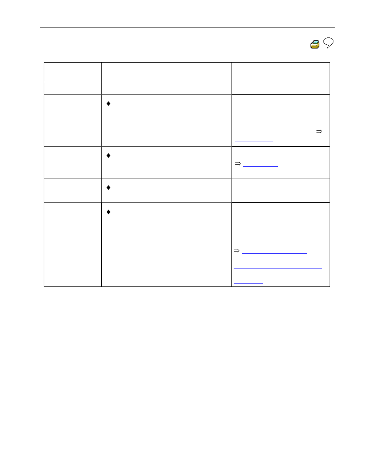
01-47
V.A.G 1551
print-out
Possible cause
Repair
00290
Left rear ABS
wheel speed
Sensor -G46-
Signal outside
tolerances1)
Open circuit, short to positive or
Ground, or loose contact in
connections between left rear ABS
wheel speed sensor -G46- and ABS
Control Module (w/EDL) -J104-
- Check wiring and
connections using wiring
diagram
- Perform electrical checks
Page 01-102
Electrical interference from other
sources (high frequency radiation e.g.
non-insulated ignition cable)
- Read measured value block
Page 01-61 Display group
number 001
Damaged rotor or left rear ABS wheel
speed sensor -G46-
Excessive air gap between left rear
ABS wheel speed sensor -G46- and
rotor (signal not OK.)
Repair Manual, Brake
System, Repair Group 45;
Removing and installing parts
of ABS system on front and
rear axles
- Check left rear ABS wheel
speed sensor -G46- and rotor
for damage
- Replace rotor/speed sensor
1)
Type of DTC; this DTC is only recognized above 20 km/h (13 mph) (carry out test drive).
Стр. 27 из 81ABS ITT Mk 20 IE On Board Diagnostic (OBD) program
Page 51
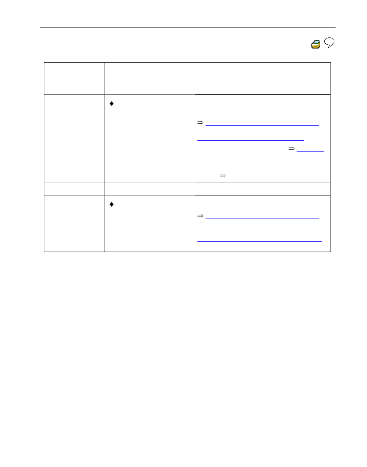
01-48
V.A.G 1551 printout
Possible cause
Repair
00290
Left rear ABS
wheel speed
sensor -G46-
Mechanical
malfunction1)
Excessive air gap
between left rear ABS
wheel speed sensor G46- and rotor (signal
not OK.)
Repair Manual, Brake System, Repair
Group 45; Removing and installing parts of
ABS system on front and rear axles
- Check installation of left rear ABS wheel
speed sensor -G46- and rotor
- Read measured value block Page 01-
61 Display group number 002
- Perform output Diagnostic Test Mode
(DTM) Page 01-74
If the malfunction occurs again:
Outlet valve in ABS
hydraulic unit -N55faulty
Repair Manual, Brake System, Repair
Group 45; Hydraulic unit, brake
booster/brake master cylinder - Assembly
overview; Removing and installing control
module and hydraulic unit
- Replace ABS hydraulic unit -N55-
1)
Type of DTC; this DTC is only recognized above 20 km/h (13 mph) (carry out test drive).
Стр. 28 из 81ABS ITT Mk 20 IE On Board Diagnostic (OBD) program
Page 52
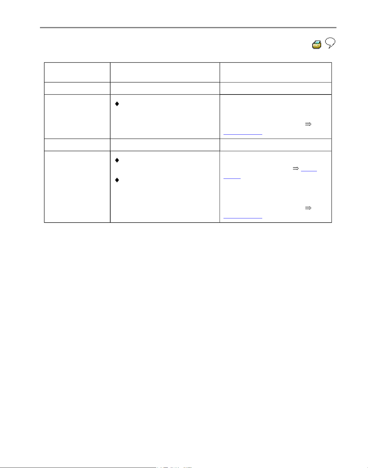
01-49
V.A.G 1551 printout
Possible cause
Repair
00668
Vehicle voltage
terminal 30
Signal outside
tolerances
Open circuit, short to positive
or Ground in the wiring
- Check wiring and connections
using wiring diagram
- Perform electrical checks
Page 01-102
01044
Control module
incorrectly coded
ABS Control Module (w/EDL) J104- incorrectly coded
Coding bridge in multi-pin
connector has open or short
circuit
- Check ABS Control Module
(w/EDL) -J104- coding Page
01-58
- Check wiring and connections
using wiring diagram
- Perform electrical checks
Page 01-102
Стр. 29 из 81ABS ITT Mk 20 IE On Board Diagnostic (OBD) program
Page 53
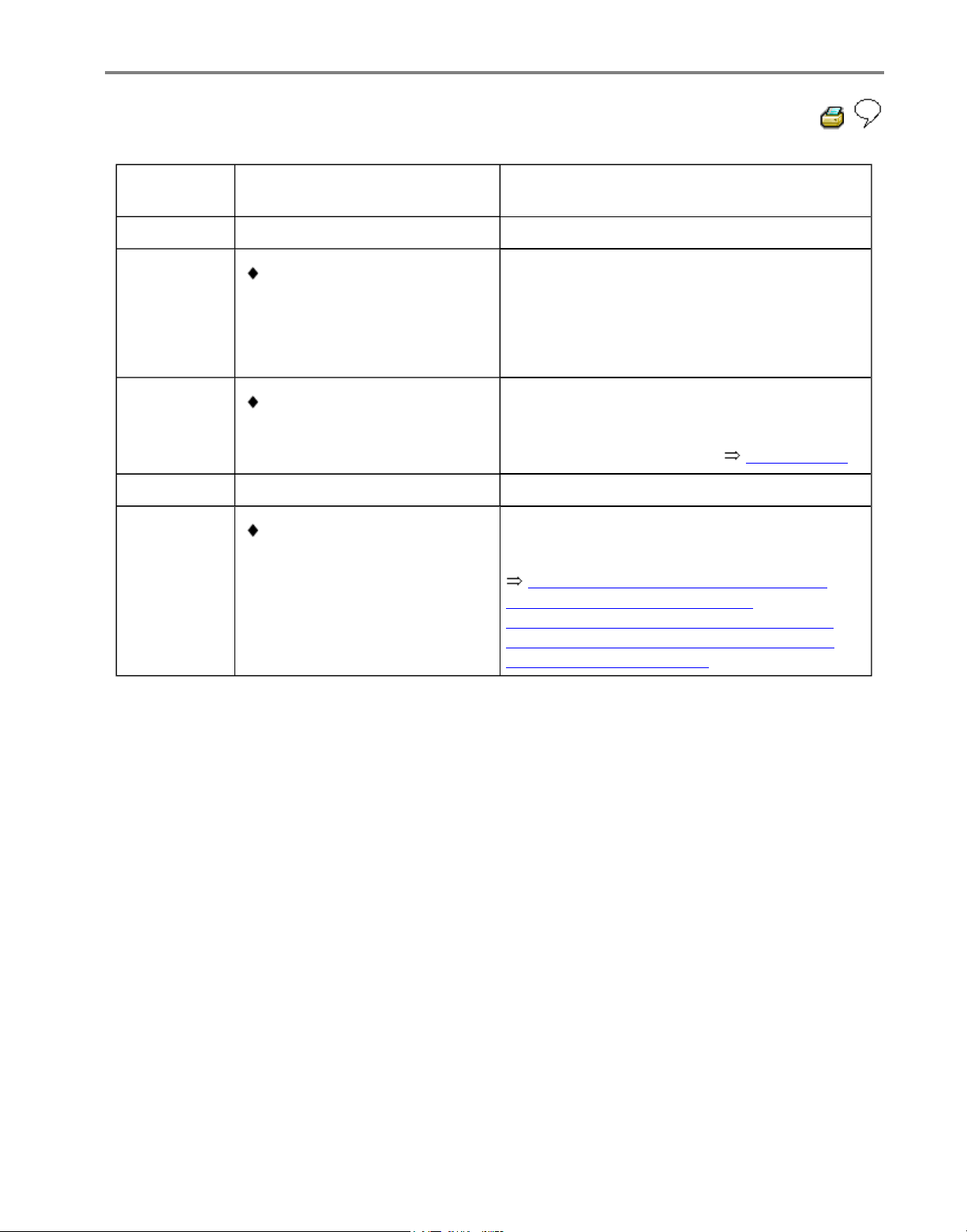
01-50
V.A.G 1551
print-out
Possible cause
Repair
01130
ABS
operation
Implausible
signal
1)
Electrical interference from
other sources (high
frequency radiation e.g.
non-insulated ignition cable)
- Erase DTC memory
- Perform test drive at more than 20 km/h
(13 mph)
- Check DTC memory again
Open circuit, short to
positive or Ground in the
wiring
- Check wiring and connections using wiring
diagram
- Perform electrical checks Page 01-102
If the malfunction occurs again:
ABS Control Module
(w/EDL) -J104- faulty
Repair Manual, Brake System, Repair
Group 45; Hydraulic unit, brake
booster/brake master cylinder - Assembly
overview; Removing and installing control
module and hydraulic unit
- Replace ABS control module (w/EDL) J104-
1)
Type of DTC; this DTC is only recognized above 20 km/h (13 mph) (carry out test drive).
Стр. 30 из 81ABS ITT Mk 20 IE On Board Diagnostic (OBD) program
Page 54
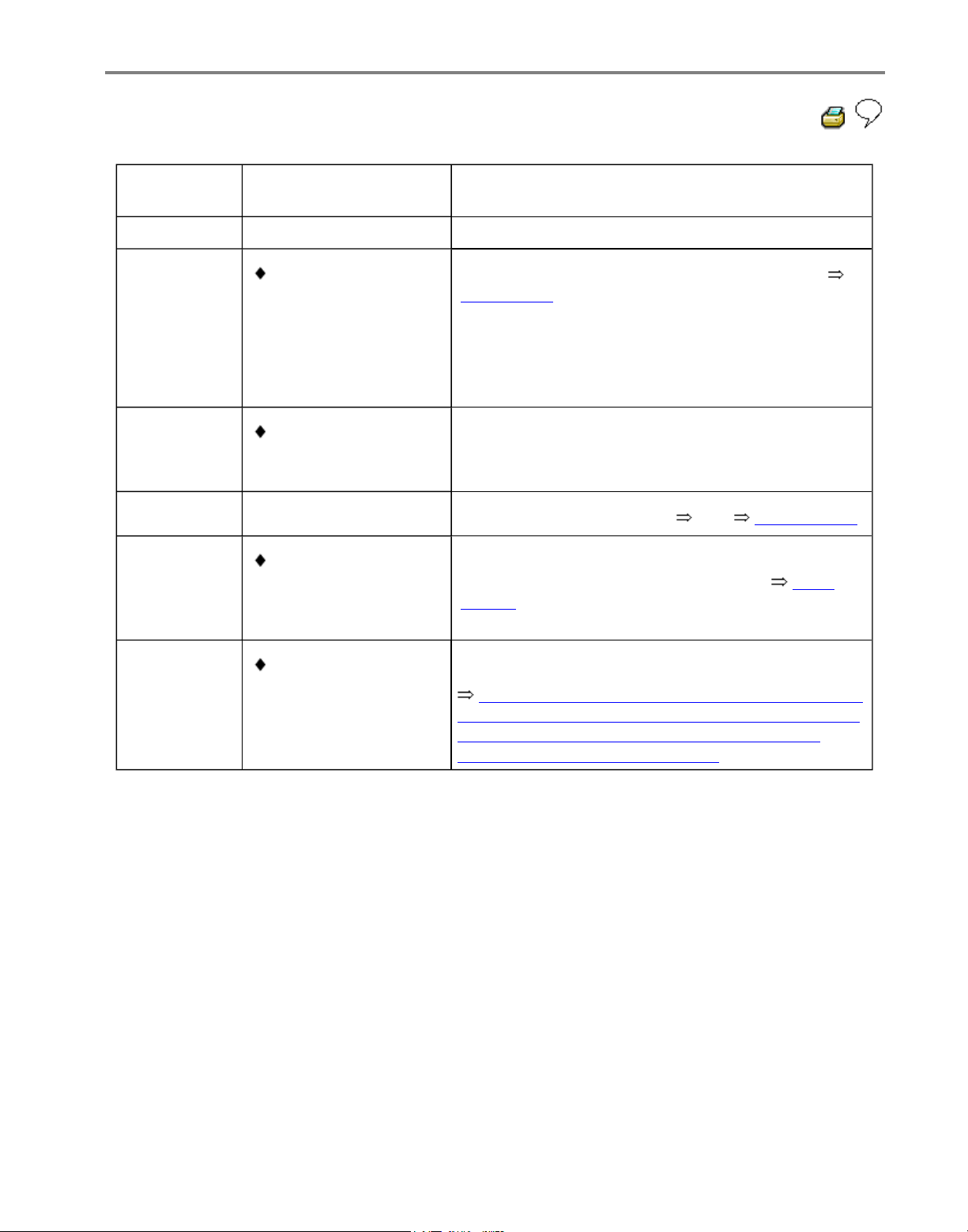
01-51
V.A.G 1551
print-out
Possible cause
Repair
01276
ABS hydraulic
pump
-V64-
Signal outside
tolerances
1)
ABS hydraulic pump
-V64-connector to
control module faulty
- Perform output Diagnostic Test Mode (DTM)
Page 01-74
Open circuit, short to
positive or Ground in
the wiring
- Check wiring and connections using wiring
diagram
- Perform electrical checks from Page 01-102
ABS hydraulic pump
-V64- faulty
- If the ABS hydraulic pump -V64- runs free while
electrical check test step 18 performed Page
01-102 , replace ABS control module (w/EDL) -
J104-
ABS control module
(w/EDL) -J104- faulty
Repair Manual, Brake System, Repair Group 45;
Hydraulic unit, brake booster/brake master cylinder
- Assembly overview; Removing and installing
control module and hydraulic unit
- Replace ABS control module (w/EDL) -J104-
1)
Type of DTC; this DTC is only recognized above 20 km/h (13 mph) (carry out test drive).
Стр. 31 из 81ABS ITT Mk 20 IE On Board Diagnostic (OBD) program
Page 55
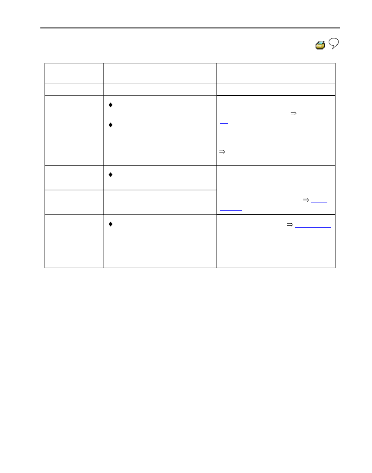
01-52
V.A.G 1551
print-out
Possible cause
Repair
01312
Drive train data
bus faulty1)
or:
ABS control module (w/EDL) J104- incorrectly coded
Engine control module
incorrectly coded
Repair group 01 for relevant
engine code
- Check ABS control module
(w/EDL) -J104- coding Page 01-
58
- Check engine control module
coding
Open circuit, short to positive or
Ground in the wiring
- Check wiring and connections
using wiring diagram
- Perform electrical checks Page
01-102
Drive train data
bus faulty1)
Sporadic
Ignition/starter switch turned
too slowly
- Erase DTC memory Page 01-56
- No further measures required
- Inform customer
1)
The DTC "Drive train data bus" will not cause the ABS warning light -K47- or warning light for
brake system -K118- to light up. The ABS function is retained over the complete range.
Стр. 32 из 81ABS ITT Mk 20 IE On Board Diagnostic (OBD) program
Page 56
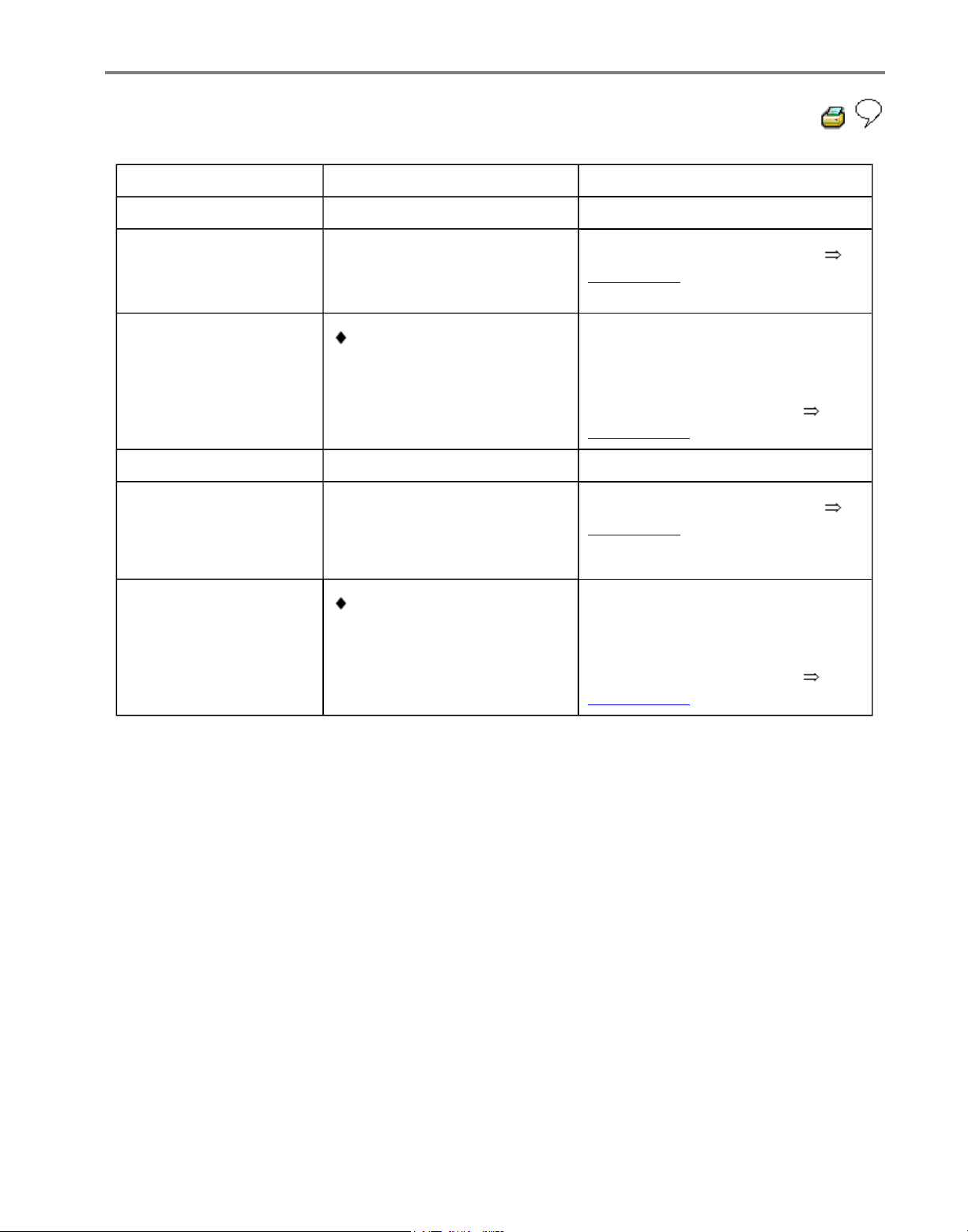
01-53
V.A.G 1551 print-out Possible cause
Repair
01314
Engine control module
No communication
- Read measured value block
Page 01-61 display group number
125
Open circuit, short to
positive or Ground in data
bus wiring
- Check wiring and connections of
data bus wiring using wiring
diagram
- Perform electrical checks
Page 01-102
01315
Transmission Control
Module (TCM)1)
No communication
- Read measured value block
Page 01-61 display group number
125
Open circuit, short to
positive or Ground in data
bus wiring
- Check wiring and connections of
data bus wiring using wiring
diagram
- Perform electrical checks
Page 01-102
1)
Vehicles with automatic transmission only.
Стр. 33 из 81ABS ITT Mk 20 IE On Board Diagnostic (OBD) program
Page 57
01-54
V.A.G 1551 printout
Possible cause
Repair
01316
Brake control
module
No
communication
Open circuit, short circuit to
positive or Ground in data bus
wiring
- Check data bus wiring and
connection using wiring diagram
- Perform electrical checks
Page 01-102
Стр. 34 из 81ABS ITT Mk 20 IE On Board Diagnostic (OBD) program
Page 58
01-55
V.A.G 1551
print-out
Possible cause Repair
18256
Check Engine
Control Module
(ECM) memory
DTC in ECM
Repair Manual, Fuel Injection & Ignition, Repair
Group 01 for relevant engine code
- Check engine control module DTC memory
65535
Control module
faulty
ABS Control
Module (w/EDL)
-J104- faulty
Repair Manual, Brake System, Repair Group 45;
Hydraulic unit, brake booster/brake master cylinder Assembly overview; Removing and installing control
module and hydraulic unit
- Replace ABS control module (w/EDL) -J104-
Стр. 35 из 81ABS ITT Mk 20 IE On Board Diagnostic (OBD) program
Page 59

01-56
Diagnostic Trouble Code (DTC)
memory, erasing and ending output
Note:
All functions which could previously be
performed with V.A.G 1551 can also be
performed with the tester VAS 5051.
Test requirements:
DTC memory checked Page 01-28 .
1. Erasing DTC memory
-
Press key.
Rapid data transfer HELP
Select function XX
Indicated on display
- Press keys -0- and -5-; 05 enters "Erase
DTC memory" function.
Rapid data transfer Q
05 - Erase DTC memor
y
Indicated on display
- Confirm entry with Q key
Rapid data transfer
DTC memory is erased!
Indicated on display
-
Press key.
Rapid data transfer HELP
Select function XX
Indicated on display
Стр. 36 из 81ABS ITT Mk 20 IE On Board Diagnostic (OBD) program
Page 60

01-57
Warning!
DTC memory was not interrogated.
Indicated on display
Note:
Adhere exactly to test sequence: First
check DTC memory, then erase
2. Ending output
- Press keys -0- and -6-, to end output.
Rapid data transfer Q
06 - End output
Indicated on display
- Confirm input with Q key.
Rapid data transfer HELP
Select function XX
Indicated on display
ABS warning light -K47- and warning light
for brake system -K118- must go out after
approx. 2 seconds.
- Switch ignition off.
- Disconnect V.A.G 1551 Scan Tool at
Data Link Connector (DLC).
- Switch ignition on.
Стр. 37 из 81ABS ITT Mk 20 IE On Board Diagnostic (OBD) program
Page 61

01-58
ABS control module, coding
All functions which could previously be
performed with V.A.G 1551 can also be
performed with the tester VAS 5051.
Warning light for ABS -K47- and warning light
for brake system -K118- flash when control
module is coded with 00000. An entry is not set
in the DTC memory.
The ABS control module (w/EDL) -J104- must
be recoded if the vehicle relevant coding is not
displayed or the control module has been
replaced.
Coding is only possible after the workshop code
(WSC) has been entered into the V.A.G 1551
Scan Tool.
Test sequence
- Connect V.A.G 1551 Scan Tool and select
(address word 03) "Brake electronics" with
ignition switched on; Page 01-23
- Establish which type of ABS hydraulic control
module is installed Page 01-4 .
- Establish engine code.
Стр. 38 из 81ABS ITT Mk 20 IE On Board Diagnostic (OBD) program
Page 62

01-59
Rapid data transfer HELP
Select function XX
Indicated on display
- Input 07 for "Code control module" and
confirm with Q key.
Rapid data transfer Q
07 - Code control module
Indicated on display
- Confirm input with Q key.
Coding control module Q
Enter code number XXXXX (0-32000
)
Indicated on display
- Enter relevant code number for this
vehicle and confirm with Q key.
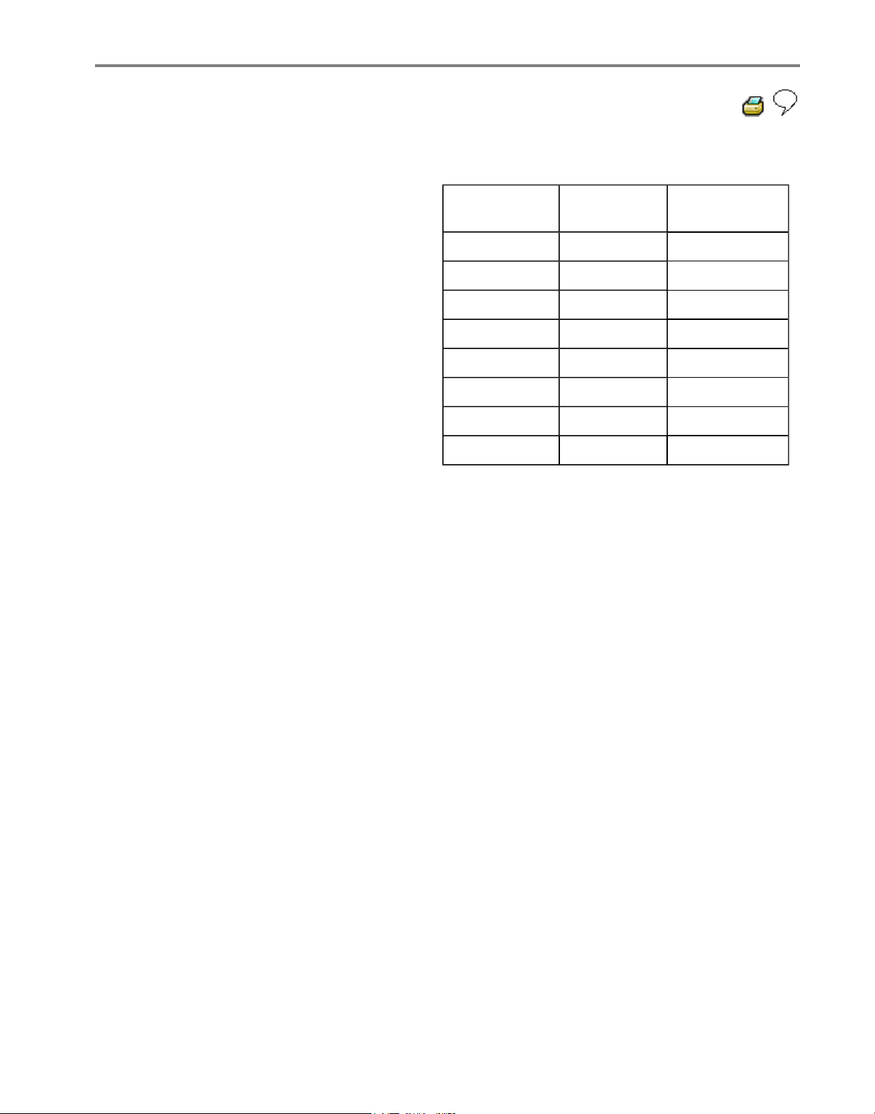
Coding variations Page 01
-60 .
1J0 907 379 D ABS 20 IE CAN 0001
Coding 03604 WSC 00000
On the display the control module
identification and coding are displayed,
e.g.:
Стр. 39 из 81ABS ITT Mk 20 IE On Board Diagnostic (OBD) program
Page 63
01-60
Coding table
Code
number
Engine
code
Variant
03504 AEG ABS
13504 AEG ABS/EDL
03504 AFP ABS
13504 AFP ABS/EDL
13204 AFP ABS/EDL/ASR
03504 ALH ABS
13504 ALH ABS/EDL
13204 APH ABS/EDL/ASR
Стр. 40 из 81ABS ITT Mk 20 IE On Board Diagnostic (OBD) program
Volkswagen Technical Site: http://volkswagen.msk.ru http://vwts.info http://vwts.ru
огромный архив документации по автомобилям Volkswagen, Skoda, Seat, Audi
Page 64

01-61
Measured value block, reading
Note:
All functions which could previously be
performed with V.A.G 1551 can also be
performed with the tester VAS 5051.
The control module can transfer a considerable
amount of test data. This test data delivers
information on the operational condition of the
system and/or sensors connected to it. In many
cases the transferred test data supports
troubleshooting and repair. The test data has
been summarized into single display groups
because all the information cannot be
evaluated at the same time. The information
can be selected via display group numbers.
Стр. 41 из 81ABS ITT Mk 20 IE On Board Diagnostic (OBD) program
Page 65

01-62
Safety precautions
Observe following if test and measuring
instruments are required during a test drive:
Test and measuring instruments must be
secured to rear seat and operated by a 2nd
person from this location.
When test and measuring instruments are
operated from the front passenger seat there is
a danger that the person sitting there could be
injured in an accident when the airbag is
triggered.
Стр. 42 из 81ABS ITT Mk 20 IE On Board Diagnostic (OBD) program
Page 66

01-63
- Connect V.A.G 1551 Scan Tool and select
address word 03 for"Brake electronics" with
ignition switched on; Page 01-23
Rapid data transfer HELP
Select function XX
Indicated on display
- Press keys 0 and 8 to select function "Read
measured value block".
Rapid data transfer Q
08 - Read measured value block
Indicated on display
- Confirm entry with key Q.
Read measured value block
Enter display group number XXX
Indicated on display
- Enter display group number List of selectable
display group numbers, Page 01
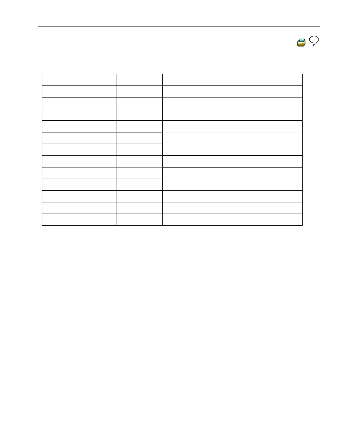
-64 .
Стр. 43 из 81ABS ITT Mk 20 IE On Board Diagnostic (OBD) program
Page 67
01-64
List of selectable display group numbers
Display group number Display zone
Designation
001 1 Wheel speed at left front wheel sensor (km/h)
2 Wheel speed at right front wheel sensor (km/h)
3 Wheel speed at left rear speed sensor (km/h)
4 Wheel speed at right rear speed sensor (km/h)
002 1 Wheel speed at left front speed sensor (km/h)
2 Wheel speed at right front wheel sensor (km/h)
3 Wheel speed at left rear speed sensor (km/h)
4 Wheel speed at right rear speed sensor (km/h)
003 1 Brake light switch
2 Vacant
3 Vacant
4 Vacant
Стр. 44 из 81ABS ITT Mk 20 IE On Board Diagnostic (OBD) program
Page 68
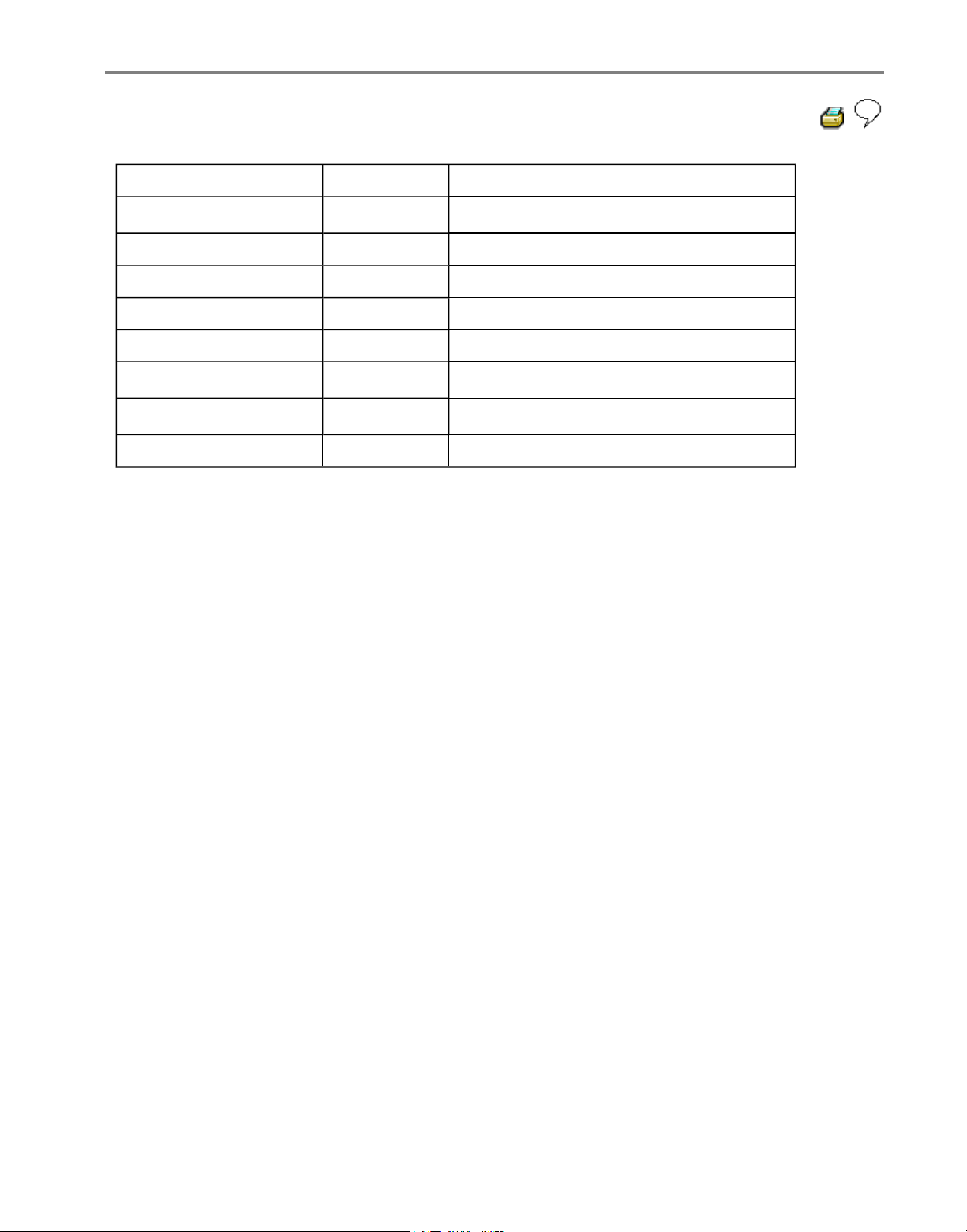
01-65
Display group number Display zone
Designation
006 1
Longitudinal acceleration sensor -G251-1)
2 Vacant
3 Vacant
4 Vacant
125 1 Data bus for engine
2
Data bus for four-wheel drive1)
3
Data bus for transmission2)
4 Vacant
1)
Four-wheel drive vehicles with Haldex coupling only.
2)
Vehicles with automatic transmission only.
Стр. 45 из 81ABS ITT Mk 20 IE On Board Diagnostic (OBD) program
Page 69
01-66
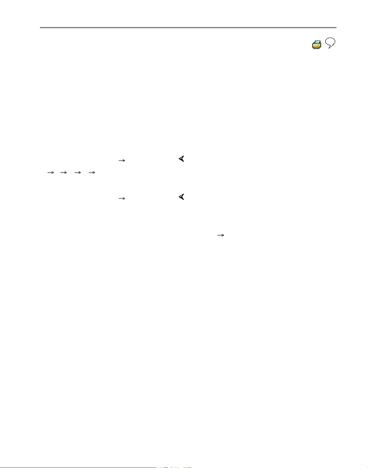
Test sequence and test tables with
measured values
Checking speed sensor allocation
Display group number 001
- Press keys 0, 0 and 1.
- Confirm entry with key Q.
Read measured value block
1
1 2 3 4
There are always 4 display zones -arrowsin the measured value block. Decoding the
individual values in display zones 1 to 4 can
be read from the following tables.
Read measured value block 1
0 km/h 0 km/h 0 km/h 0 km/h
Indicated on display: (vehicle stationary)
Press C key for the next display group
number entry.
If the key is pressed, keys 0 and 8 for
work sequence "Read measured value
block" must be pressed again afterwards to
regain entry.
Стр. 46 из 81ABS ITT Mk 20 IE On Board Diagnostic (OBD) program
Page 70
01-67
Note:
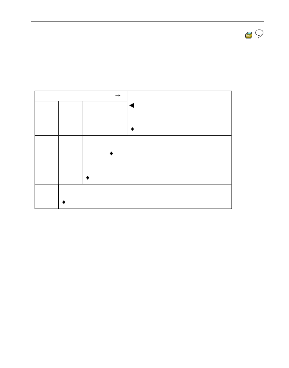
For display group number 001 remember:
The actual wheel speeds are displayed. They serve to check the speed sensor allocation to the
wheel. (The vehicle must be raised and the wheel must be rotated by hand by a 2nd mechanic).
Read measured value block
1
Display group number: 001
0 km/h 4 km/h 0 km/h 0 km/h
Indicated on display: (Example)
Wheel speed at right rear speed sensor
(0 to 255 km/h)
Wheel speed at left rear speed sensor
(0 to 255 km/h)
Wheel speed at right front speed sensor
(0 to 255 km/h)
Wheel speed at left front speed sensor
(0 to 255 km/h)
Стр. 47 из 81ABS ITT Mk 20 IE On Board Diagnostic (OBD) program
Page 71
01-68
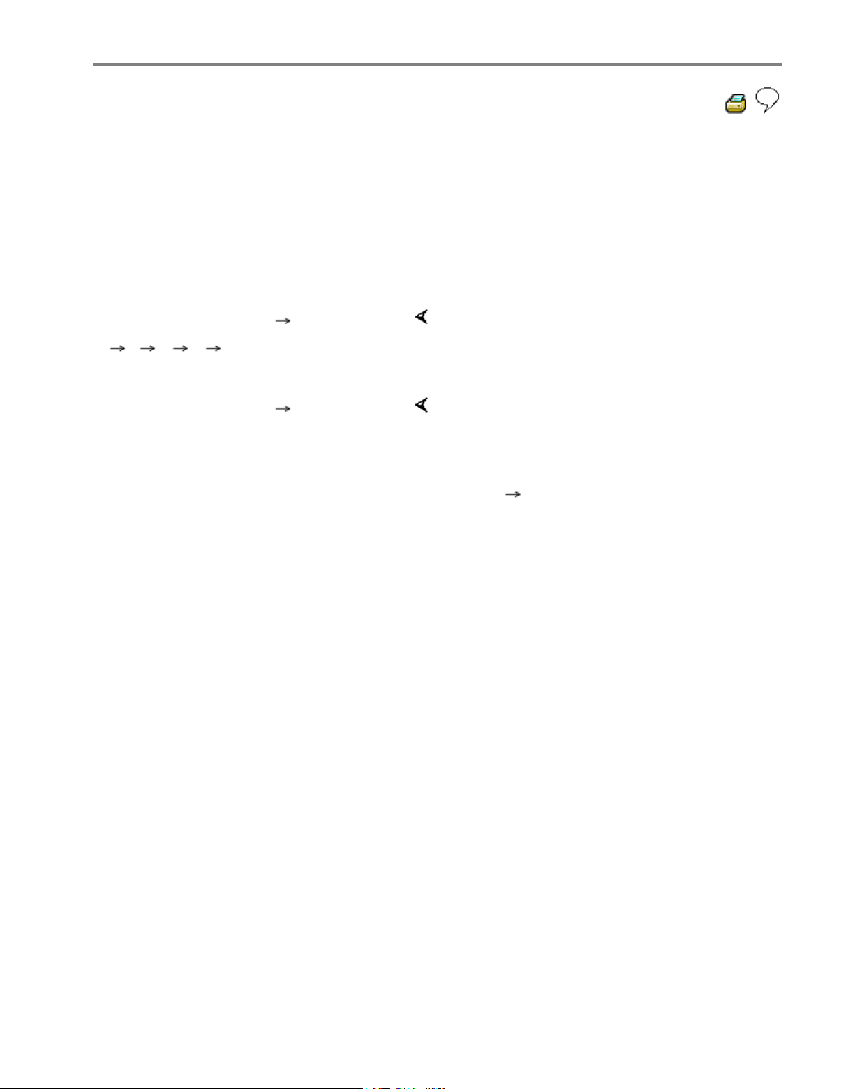
Checking speed sensor
Display group number 002
- Press keys 0, 0 and 2.
- Confirm entry with key Q.
Read measured value block
2
1 2 3 4
There are always 4 display zones -arrowsin the measured value block. Decoding the
individual values in display zones 1 to 4 can
be read from the following tables.
Read measured value block 2
255 km/h 255 km/h 255 km/h 255 km/h
Indicated on display: (Vehicle stationary)
Press C key for the next display group
number entry.
If the key is pressed, keys 0 and 8 for
work sequence "Read measured value
block" must be pressed again afterwards to
regain entry.
Стр. 48 из 81ABS ITT Mk 20 IE On Board Diagnostic (OBD) program
Page 72
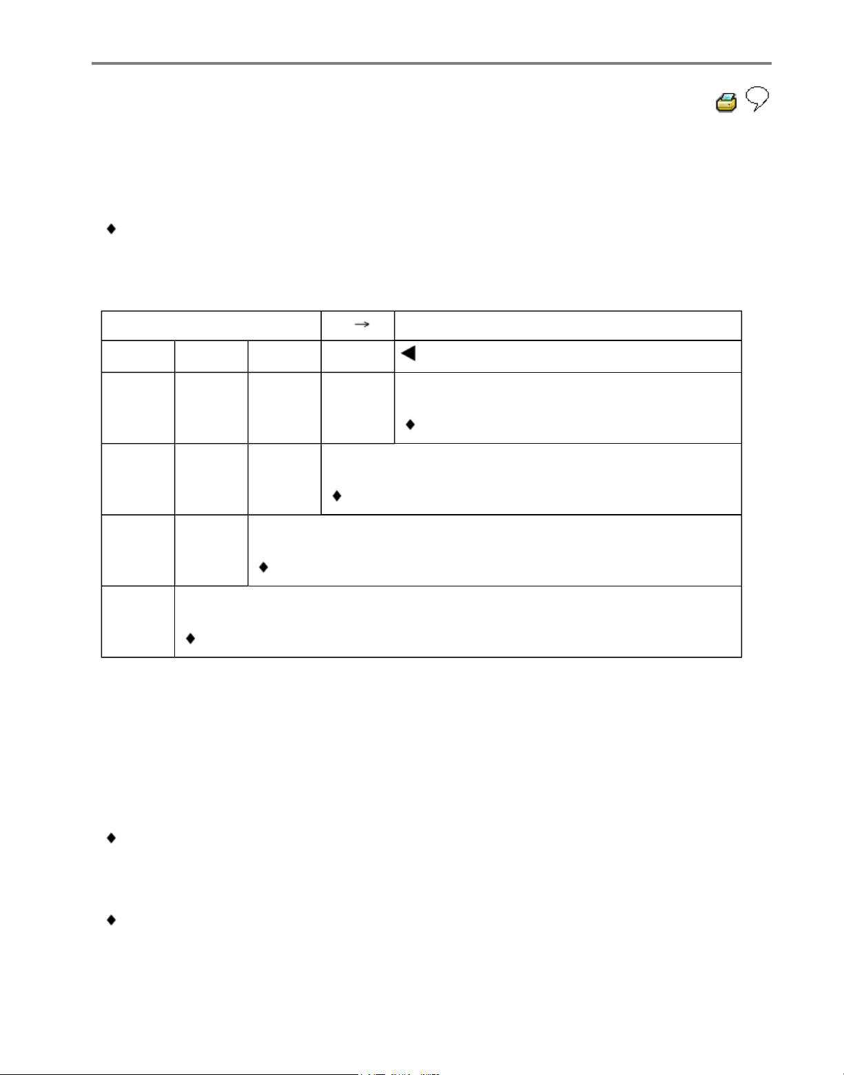
01-69
Note:
For display group number 002 remember:
The reading of measured value blocks in display group number 002 must be undertaken
when driving off slowly. Then the ABS Control Module (w/EDL) -J104- will store the first
usable voltage signals provided by the speed sensors and display these as a fixed value in
the measured value block.
Read measured value block
2
Display group number: 002
3 km/h1) 6 km/h1) 2 km/h2) 1 km/h2)
Indicated on display: (when driving off slowly)
Wheel speed at right rear speed sensor
(0 to 255 km/h)
Wheel speed at left rear speed sensor
(0 to 255 km/h)
Wheel speed at right front speed sensor
(0 to 255 km/h)
Wheel speed at left front speed sensor
(0 to 255 km/h)
1)
If the deviations in display zones 1 and 2 are greater than 6 km/h (approx. 3.75 mph), the
following malfunctions may be present:
2)
If the deviations in display zones 3 and 4 are greater than 2 km/h (approx. 1.25 mph), the
following malfunctions may be present:
Note:
Air gap between speed sensor and rotor may be too wide.
- Check that speed sensor is attached correctly to wheel bearing housing.
Speed sensor or rotor exterior damaged.
- Change damaged component.
Стр. 49 из 81ABS ITT Mk 20 IE On Board Diagnostic (OBD) program
Page 73
01-70
Checking brake light switch for ABS and
ABS/EDL function
Display group number 003
- Press keys 0, 0 and 3
- Confirm entry with key Q.
Read measured value block
3
1 2 3 4
There are always 4 display zones -arrowsin the measured value block. Decoding the
individual values in display zones 1 to 4 can
be read from the following tables.
Read measured value block 3
0
Indicated on display
Press C key for the next display group
number entry.
If the key is pressed, keys 0 and 8 for
work sequence "Read measured value
block" must be pressed again afterwards to
regain entry.
Стр. 50 из 81ABS ITT Mk 20 IE On Board Diagnostic (OBD) program
Page 74
01-71
Read measured value block
3
Display group number: 003
0
Indicated on display
Vacant
Vacant
Vacant
Brake light switch:
If despite pressed foot brake a -0-, or not pressed foot brake a -1- is displayed on the
V.A.G 1551 display; perform test step No. 4 of Electrical check, Page 01-102 .
There is also a possibility that the brake light switch has not been correctly adjusted.
Adjusting brake light switch, Page 01-131 .
0 Brake pedal not depressed
1 Brake pedal depressed
Стр. 51 из 81ABS ITT Mk 20 IE On Board Diagnostic (OBD) program
Page 75
01-72
Checking data bus wiring
Display group number 125
- Press keys 1, 2 and 5
- Confirm entry with key Q.
Read measured value block
125
1 2 3 4
There are always 4 display zones -arrowsin the measured value block. Decoding the
individual values in display zones 1 to 4 can
be read from the following tables.
Read measured value block
125
Engine 1 4WD 1 Gear. 1
Indicated on display: (vehicle stationary)
Press C key for the next display group
number entry.
If the key is pressed, keys 0 and 8 for
work sequence "Read measured value
block" must be pressed again afterwards to
regain entry.
Стр. 52 из 81ABS ITT Mk 20 IE On Board Diagnostic (OBD) program
Page 76
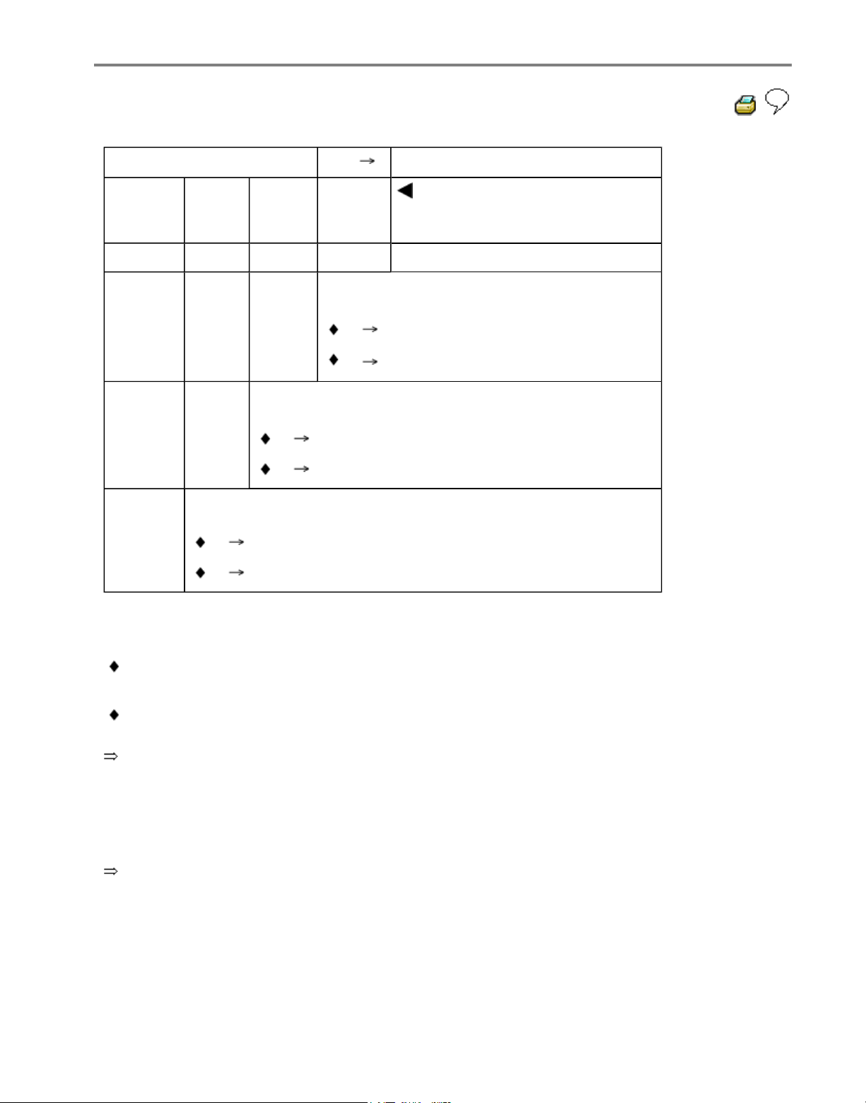
01-73
Read measured value block
125
Display group number: 125
Engine
1
AWD
1
Gear.
1
Indicated on display (example)
Vacant
Data bus connection for transmission1)
1 Data bus connection is available.
0 Data bus connection is not available.3)
Data bus for all-wheel drive2)
1 Data bus connection is available.
0 Data bus connection is available.
Data bus for engine
1 Data bus connection is available.
0 Data bus connection is not available.
1)
Vehicles with automatic transmission only.
Incorrect transmission control module or incorrect transmission control module coding.
Transmission control module faulty.
Repair Group 01 for relevant transmission code.
2)
All-wheel drive vehicles with Haldex coupling only.
3)
Data bus connection is interrupted or data bus wires are interchanged.
Electrical Wiring Diagrams, Troubleshooting & Component Locations binder.
Стр. 53 из 81ABS ITT Mk 20 IE On Board Diagnostic (OBD) program
Page 77

01-74
Output Diagnostic Test Mode (DTM)
Note:
All functions which could previously be
performed with V.A.G 1551 can also be
performed with the tester VAS 5051.
The pump motor and the correct functioning of
the hydraulic circuits (allocation of brake lines to
wheel cylinders and function of valves) can be
checked via the output DTM for interchange or
leaks.
The vehicle must be raised until all wheels are
free to turn. (2nd mechanic required to rotate
wheels)
The -C- key can be used to exit the test
sequence at any time.
After depressing the brake pedal several times
the vacuum in the brake booster will be
exhausted. Therefore more pressure must be
applied to the brake pedal in order to attain the
same fluid pressure in brake system, as that
attained with vacuum.
When vacuum in brake booster is exhausted
wheels may not lock; start engine and build-up
vacuum in brake booster.
Стр. 54 из 81ABS ITT Mk 20 IE On Board Diagnostic (OBD) program
Page 78
01-75
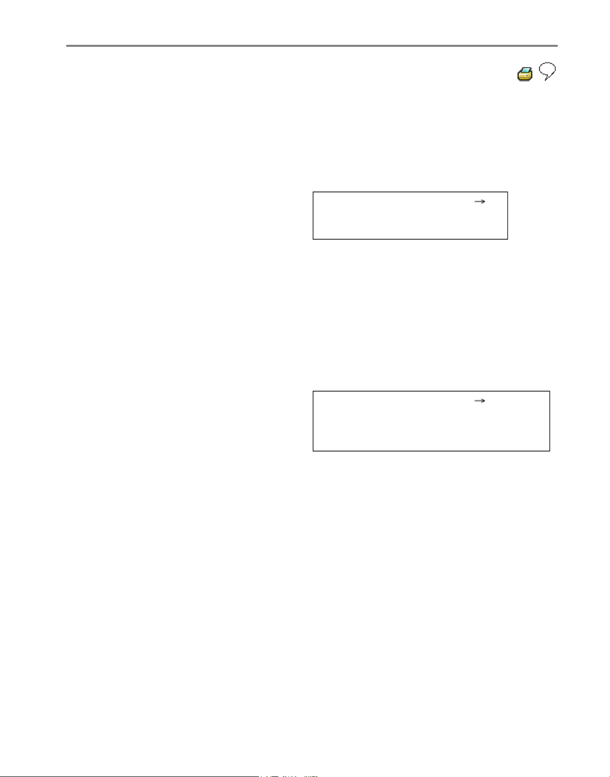
Example:
Indicated on V.A.G 1551 display during output
Diagnostic Test Mode (DTM):
(e.g. front left wheel, FL)
Output Diagnostic Test Mode -
IFL: VBAT OFL: 0V Wheel FL locked
IFL = Inlet valve Front Left
VBAT = Voltage Battery; Voltage at valve
OFL = Outlet valve Front Left
0V = 0 Volt; No voltage at valve
Locked/free = Wheel condition; must be
checked by 2nd mechanic if required
Output Diagnostic Test Mode -
EDL valves/Hyd-P: VBAT Wheel FL/FR
locked
Hydr-P = Hydraulic pump
Стр. 55 из 81ABS ITT Mk 20 IE On Board Diagnostic (OBD) program
Page 79

01-76
- Connect V.A.G 1551 Scan Tool.
- Switch ignition on.
- Press key -1- for "Rapid data transfer" operating
mode.
- Select brake electronics (address word 03);
Page 01
-23
Rapid data transfer Q
03 - Brake electronics
Indicated on display
Note:
During the next work steps the ABS warning light K47- flashes.
- Confirm entry with key Q.
- Read off control module version in V.A.G 1551
display.
-
Press key.
Стр. 56 из 81ABS ITT Mk 20 IE On Board Diagnostic (OBD) program
Page 80
01-77
Rapid data transfer HELP
Select function XX
Indicated on display
- Press keys 0 and 3
Rapid data transfer Q
03 - Output Diagnostic Test Mode
Indicated on display
- Confirm entry with key Q.
ABS hydraulic pump -V64- must run.
Output Diagnostic Test Mode
-
ABS hydraulic pump - V64
Indicated on display
-
Press key.
Output Diagnostic Test Mode
-
Operate brakes
Indicated on display
- Operate brake pedal.
-
Press key.
Output Diagnostic Test Mode
-
IFL: 0V OFL: 0V Wheel FL locked
Indicated on display
Note:
If the wheel does not lock, there is a
possibility that there is a malfunction in the
mechanical/hydraulic part of the brake
system.
- Indicate to 2nd mechanic which wheel
requires turning by hand.
Стр. 57 из 81ABS ITT Mk 20 IE On Board Diagnostic (OBD) program
Page 81

01-78
-
Press key.
Output Diagnostic Test Mode
-
IFL: VBAT OFL: 0V Wheel FL locked
Indicated on display
If the brake pedal gives, there is a
malfunction in the hydraulic unit. In this
case the hydraulic unit must be replaced.
Repair Manual, Brake System, Repair
Group 45; Hydraulic unit, brake
booster/brake master cylinder - Assembly
overview; Removing and installing control
module and hydraulic unit
-
Press key.
ABS hydraulic pump -V64- must run.
Brake pedal must not give.
Output Diagnostic Test Mode
-
IFL: VBAT OFL: VBAT Wheel FL free
Indicated on display
Note:
If the wheel locks there is a possibility that
the brake lines to the wheel
calipers/cylinders have been interchanged.
- Indicate to 2nd mechanic which wheel
requires turning by hand.
Стр. 58 из 81ABS ITT Mk 20 IE On Board Diagnostic (OBD) program
Page 82

01-79
-
Press key.
ABS hydraulic pump -V64- no longer
runs.
Output Diagnostic Test Mode
-
IFL: VBAT OFL: 0V Wheel FL free
Indicated on display
If the brake pedal does not give, there is a
malfunction in the hydraulic unit. In this
case the hydraulic unit must be replaced.
Repair Manual, Brake System, Repair
Group 45; Hydraulic unit, brake
booster/brake master cylinder - Assembly
overview; Removing and installing control
module and hydraulic unit
-
Press key.
Brake pedal must give perceptibly
Output Diagnostic Test Mode
-
IFL: 0V OFL: 0V Wheel FL locked
Indicated on display
Note:
If the wheel does not lock, there is a
possibility that there is a malfunction in the
mechanical/hydraulic part of the brake
system.
- Indicate to 2nd mechanic which wheel
requires turning by hand.
Стр. 59 из 81ABS ITT Mk 20 IE On Board Diagnostic (OBD) program
Page 83

01-80
-
Press key.
Output Diagnostic Test Mode
-
Release brakes
Indicated on display
- Remove foot from brake pedal.
-
Press key.
Output Diagnostic Test Mode
-
Operate brakes
Indicated on display
- Operate brake pedal.
-
Press key.
Output Diagnostic Test Mode
-
IFR: 0V OFR: 0V Wheel FR locked
Indicated on display
Note:
If the wheel does not lock, there is a
possibility that there is a malfunction in the
mechanical/hydraulic part of the brake
system.
- Indicate to 2nd mechanic which wheel
requires turning by hand.
Стр. 60 из 81ABS ITT Mk 20 IE On Board Diagnostic (OBD) program
Page 84

01-81
-
Press key.
Output Diagnostic Test Mode
-
IFR: VBAT OFR: 0V Wheel FR locked
Indicated on display
If the brake pedal gives, there is a
malfunction in the hydraulic unit. In this
case the hydraulic unit must be replaced.
Repair Manual, Brake System, Repair
Group 45; Hydraulic unit, brake
booster/brake master cylinder - Assembly
overview; Removing and installing control
module and hydraulic unit
-
Press key.
ABS hydraulic pump -V64- must run.
Brake pedal must not give
Output Diagnostic Test Mode
-
IFR: VBAT OFR: VBAT Wheel FR free
Indicated on display
Note:
If the wheel locks there is a possibility that
the brake lines to the wheel
calipers/cylinders have been interchanged.
- Indicate to 2nd mechanic which wheel
requires turning by hand.
Стр. 61 из 81ABS ITT Mk 20 IE On Board Diagnostic (OBD) program
Page 85

01-82
-
Press key.
ABS hydraulic pump -V64- no longer
runs.
Output Diagnostic Test Mode
-
IFR: VBAT OFR: 0V Wheel FR free
Indicated on display
If the brake pedal does not give, there is a
malfunction in the hydraulic unit. In this
case the hydraulic unit must be replaced.
Repair Manual, Brake System, Repair
Group 45; Hydraulic unit, brake
booster/brake master cylinder - Assembly
overview; Removing and installing control
module and hydraulic unit
-
Press key.
Brake pedal must give perceptibly
Output Diagnostic Test Mode
-
IFR: 0V OFR: 0V Wheel FR locked
Indicated on display
Note:
If the wheel does not lock, there is a
possibility that there is a malfunction in the
mechanical/hydraulic part of the brake
system.
- Indicate to 2nd mechanic which wheel
requires turning by hand.
Стр. 62 из 81ABS ITT Mk 20 IE On Board Diagnostic (OBD) program
Page 86

01-83
-
Press key.
Output Diagnostic Test Mode
-
Release brakes
Indicated on display
- Remove foot from brake pedal.
-
Press key.
Output Diagnostic Test Mode
-
Operate brakes
Indicated on display
- Operate brake pedal.
-
Press key.
Output Diagnostic Test Mode
-
IRL: 0V ORL: 0V Wheel RL locked
Indicated on display
Note:
If the wheel does not lock, there is a
possibility that there is a malfunction in the
mechanical/hydraulic part of the brake
system.
- Indicate to 2nd mechanic which wheel
requires turning by hand.
Стр. 63 из 81ABS ITT Mk 20 IE On Board Diagnostic (OBD) program
Page 87

01-84
-
Press key.
Output Diagnostic Test Mode
-
IRL: VBAT ORL: 0V Wheel RL locked
Indicated on display
If the brake pedal gives, there is a
malfunction in the hydraulic unit. In this
case the hydraulic unit must be replaced.
Repair Manual, Brake System, Repair
Group 45; Hydraulic unit, brake
booster/brake master cylinder - Assembly
overview; Removing and installing control
module and hydraulic unit
-
Press key.
ABS hydraulic pump -V64- must run.
Brake pedal must not give
Output Diagnostic Test Mode
-
IRL: VBAT ORL: VBAT Wheel RL free
Indicated on display
Note:
If the wheel locks there is a possibility that
the brake lines to the wheel
calipers/cylinders have been interchanged.
- Indicate to 2nd mechanic which wheel
requires turning by hand.
Стр. 64 из 81ABS ITT Mk 20 IE On Board Diagnostic (OBD) program
Page 88

01-85
-
Press key.
ABS hydraulic pump -V64 no longer
runs.
Output Diagnostic Test Mode
-
IRL: VBAT ORL: 0V Wheel RL free
Indicated on display
If the brake pedal does not give, there is a
malfunction in the hydraulic unit. In this
case the hydraulic unit must be replaced.
Repair Manual, Brake System, Repair
Group 45; Hydraulic unit, brake
booster/brake master cylinder - Assembly
overview; Removing and installing control
module and hydraulic unit
-
Press key.
Brake pedal must give perceptibly
Output Diagnostic Test Mode
-
IRL: 0V ORL: 0V Wheel RL locked
Indicated on display
Note:
If the wheel does not lock, there is a
possibility that there is a malfunction in the
mechanical/hydraulic part of the brake
system.
- Indicate to 2nd mechanic which wheel
requires turning by hand.
Стр. 65 из 81ABS ITT Mk 20 IE On Board Diagnostic (OBD) program
Page 89

01-86
-
Press key.
Output Diagnostic Test Mode
-
Release brakes
Indicated on display
- Remove foot from brake pedal.
-
Press key.
Output Diagnostic Test Mode
-
Operate brakes
Indicated on display
- Operate brake pedal.
-
Press key.
Output Diagnostic Test Mode
-
IRR: 0V ORR: 0V Wheel RR locked
Indicated on display
Note:
If the wheel does not lock, there is a
possibility that there is a malfunction in the
mechanical/hydraulic part of the brake
system.
- Indicate to 2nd mechanic which wheel
requires turning by hand.
Стр. 66 из 81ABS ITT Mk 20 IE On Board Diagnostic (OBD) program
Page 90

01-87
-
Press key.
Output Diagnostic Test Mode
-
IRR: VBAT ORR: 0V Wheel RR locked
Indicated on display
If the brake pedal gives, there is a
malfunction in the hydraulic unit. In this
case the hydraulic unit must be replaced.
Repair Manual, Brake System, Repair
Group 45; Hydraulic unit, brake
booster/brake master cylinder - Assembly
overview; Removing and installing control
module and hydraulic unit
-
Press key.
ABS hydraulic pump -V64- must run.
Brake pedal must not give
Output Diagnostic Test Mode
-
IRR: VBAT ORR: VBAT Wheel RR free
Indicated on display
Note:
If the wheel locks there is a possibility that
the brake lines to the wheel
calipers/cylinders have been interchanged.
- Indicate to 2nd mechanic which wheel
requires turning by hand.
Стр. 67 из 81ABS ITT Mk 20 IE On Board Diagnostic (OBD) program
Page 91

01-88
-
Press key.
ABS hydraulic pump -V64- no longer
runs.
Output Diagnostic Test Mode
-
IRR: VBAT ORR: 0V Wheel RR free
Indicated on display
If the brake pedal does not give, there is a
malfunction in the hydraulic unit. In this
case the hydraulic unit must be replaced.
Repair Manual, Brake System, Repair
Group 45; Hydraulic unit, brake
booster/brake master cylinder - Assembly
overview; Removing and installing control
module and hydraulic unit
-
Press key
Brake pedal must give perceptibly
Output Diagnostic Test Mode
-
IRR: 0V ORR: 0V Wheel RR locked
Indicated on display
Note:
If the wheel does not lock, there is a
possibility that there is a malfunction in the
mechanical/hydraulic part of the brake
system.
- Indicate to 2nd mechanic which wheel
requires turning by hand.
Стр. 68 из 81ABS ITT Mk 20 IE On Board Diagnostic (OBD) program
Page 92

01-89
-
Press key.
Output Diagnostic Test Mode
-
Release brakes
Indicated on display
- Remove foot from brake pedal.
-
Press key.
Output Diagnostic Test Mode
-
EDL valves/Hyd-P: VBAT Wh FL/FR locked
Indicated on display (vehicles with EDL)
Note:
A 2nd mechanic is required to rotate the
respective wheel by hand.
If the wheels do not lock, there is a
malfunction in the hydraulic part of the ABS
system. In this case the hydraulic unit must
be replaced.
Repair Manual, Brake System, Repair
Group 45; Hydraulic unit, brake
booster/brake master cylinder - Assembly
overview; Removing and installing control
module and hydraulic unit
Стр. 69 из 81ABS ITT Mk 20 IE On Board Diagnostic (OBD) program
Page 93

01-90
-
Press key.
The ABS warning light -K47- goes out.
Function is unknown or
cannot be carried out at the moment
Indicated on display
The Output Diagnostic Test Mode (DTM) is
completed
-
Press key.
Rapid data transfer HELP
Select function XX
Indicated on display
Note:
There is a malfunction in the system if
the ABS warning light -K47- does not go
out.
Adhere exactly to test sequence: First
check Diagnostic Trouble Code (DTC)
memory, then erase.
- End output (Function 06) Page 01-56 .
Стр. 70 из 81ABS ITT Mk 20 IE On Board Diagnostic (OBD) program
Page 94
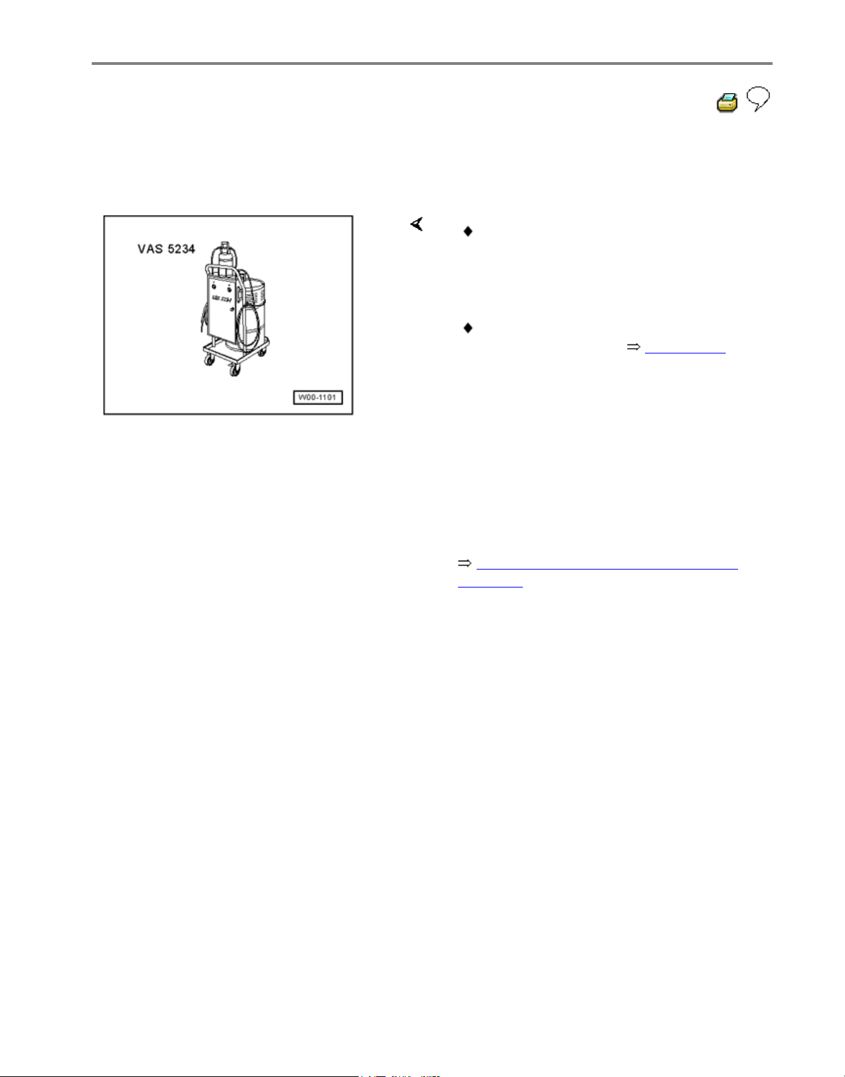
01-91
Basic setting, initiating
Special tools and equipment
Function 04 "Initiate basic settings"
performs several functions:
Note:
The basic setting to bleed the hydraulic unit
is only required when one chamber of the
brake fluid reservoir is completely empty.
The basic setting is used to bleed the
hydraulic unit only. The brake system
must be bleed separately.
Repair Manual, Brake System, Repair
Group 47
VAS 5234 Brake filler and bleeder unit
Display group 001 is required to bleed
the hydraulic system Page 01-91
Стр. 71 из 81ABS ITT Mk 20 IE On Board Diagnostic (OBD) program
Page 95
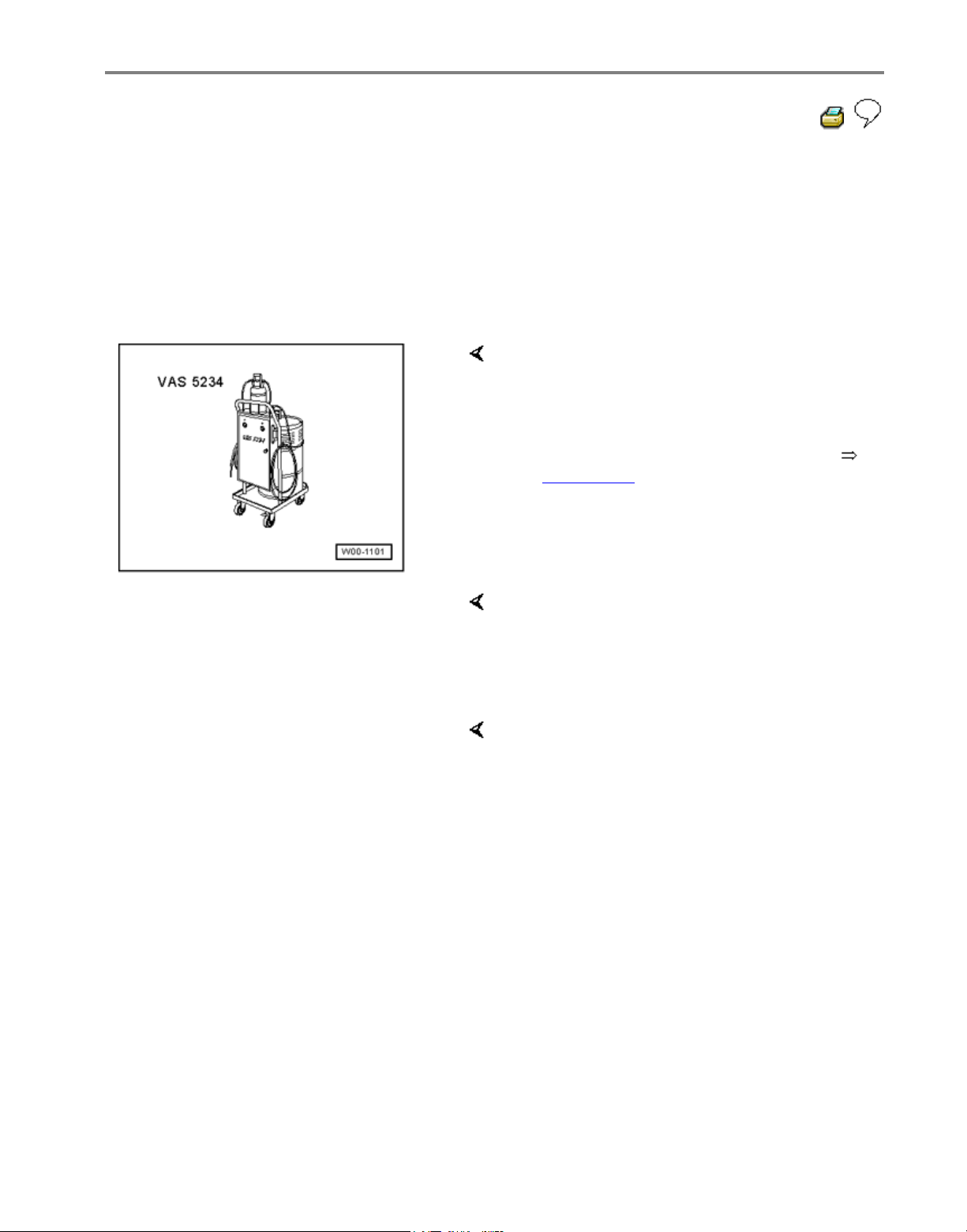
01-92
Display group number 01: Bleeding
hydraulic unit.
Note:
All functions which could previously be
performed with V.A.G 1551 can also be
performed with the tester VAS 5051.
- Connect VAS 5234 Brake filler and
bleeder unit.
- Connect V.A.G 1551 Scan Tool and
select (address word 03) "Brake
electronics" with ignition switched on;
Page 01-23
Rapid data transfer HELP
Select function XX
Indicated on display
- Press keys 0 and 4. (The function
"Initiating basic setting" is selected with
04).
Rapid data transfer Q
04 - Basic settin
g
Indicated on display
- Confirm entry with key Q.
Стр. 72 из 81ABS ITT Mk 20 IE On Board Diagnostic (OBD) program
Page 96

01-93
Basic setting HELP
Enter display group number XXX
Indicated on display:
- Press keys 0, 0 and 1
- Confirm entry with key Q.
System in basic setting 1
Depress pedal and hold...
Indicated on display:
- Operate pedal with substantial foot
pressure and hold.
Pedal moves down
Hydraulic pump runs
Pedal comes back
System in basic setting 1
Rel. pedal; FR/FL bleed screw OPEN <3>
Indicated on display
- Press key 3 on V.A.G 1551 or arrow up
key on VAS 5051.
System in basic setting 2
Please wait...(10 secs.
)
Indicated on display
Hydraulic pump runs
System in basic setting 2
Depr. pedal 10X; bleed screw CLOSED <3>
Indicated on display
- Press key 3 on V.A.G 1551 or arrow up
key on VAS 5051.
Стр. 73 из 81ABS ITT Mk 20 IE On Board Diagnostic (OBD) program
Page 97

01-94
System in basic setting 3
Depress pedal and hold...
Indicated on display
- Operate pedal with substantial foot
pressure and hold.
Pedal moves down
Hydraulic pump runs
Pedal comes back
System in basic setting 3
Rel. pedal; FR/FL bleed screw OPEN <3>
Indicated on display
- Press key 3 on V.A.G 1551 or arrow up
key on VAS 5051.
System in basic setting 4
Please wait...(10 secs.
)
Indicated on display
Hydraulic pump runs
System in basic setting 4
Depr. pedal 10X; bleed screw CLOSED <3>
Indicated on display
- Press key 3 on V.A.G 1551 or arrow up
key on VAS 5051.
Стр. 74 из 81ABS ITT Mk 20 IE On Board Diagnostic (OBD) program
Page 98

01-95
System in basic setting 5
Depress pedal and hold...
Indicated on display
- Operate pedal with substantial foot
pressure and hold.
Pedal moves down
Hydraulic pump runs
Pedal comes back
System in basic setting 5
Rel. pedal; FR/FL bleed screw OPEN <3>
Indicated on display
- Press key 3 on V.A.G 1551 or arrow up
key on VAS 5051.
System in basic setting 6
Please wait...(10 secs.
)
Indicated on display
Hydraulic pump runs
System in basic setting 6
Depr. pedal 10X; bleed screw CLOSED <3>
Indicated on display
- Press key 3 on V.A.G 1551 or arrow up
key on VAS 5051.
Стр. 75 из 81ABS ITT Mk 20 IE On Board Diagnostic (OBD) program
Page 99

01-96
System in basic setting 7
Depress pedal and hold...
Indicated on display
- Operate pedal with substantial foot
pressure and hold.
Pedal moves down
Hydraulic pump runs
Pedal comes back
System in basic setting 7
Rel. pedal; FR/FL bleed screw OPEN <3>
Indicated on display
- Press key 3 on V.A.G 1551 or arrow up
key on VAS 5051.
System in basic setting 8
Please wait...(10 secs.
)
Indicated on display
Hydraulic pump runs
System in basic setting 8
Depr. pedal 10X; bleed screw CLOSED <3>
Indicated on display
- Press key 3 on V.A.G 1551 or arrow up
key on VAS 5051.
Стр. 76 из 81ABS ITT Mk 20 IE On Board Diagnostic (OBD) program
Page 100

01-97
System in basic setting 9
Depress pedal and hold...
Indicated on display
- Operate pedal with substantial foot
pressure and hold.
Pedal moves down
Hydraulic pump runs
Pedal comes back
System in basic setting 9
Rel. pedal; FR/FL bleed screw OPEN <3>
Indicated on display
- Press key 3 on V.A.G 1551 or arrow up
key on VAS 5051.
System in basic setting 10
Please wait...(10 secs.
)
Indicated on display
Hydraulic pump runs
System in basic setting 10
Depr. pedal 10X; bleed screw CLOSED <3>
Indicated on display
- Press key 3 on V.A.G 1551 or arrow up
key on VAS 5051.
Стр. 77 из 81ABS ITT Mk 20 IE On Board Diagnostic (OBD) program
 Loading...