

Page 1

Page 2127
Page 2
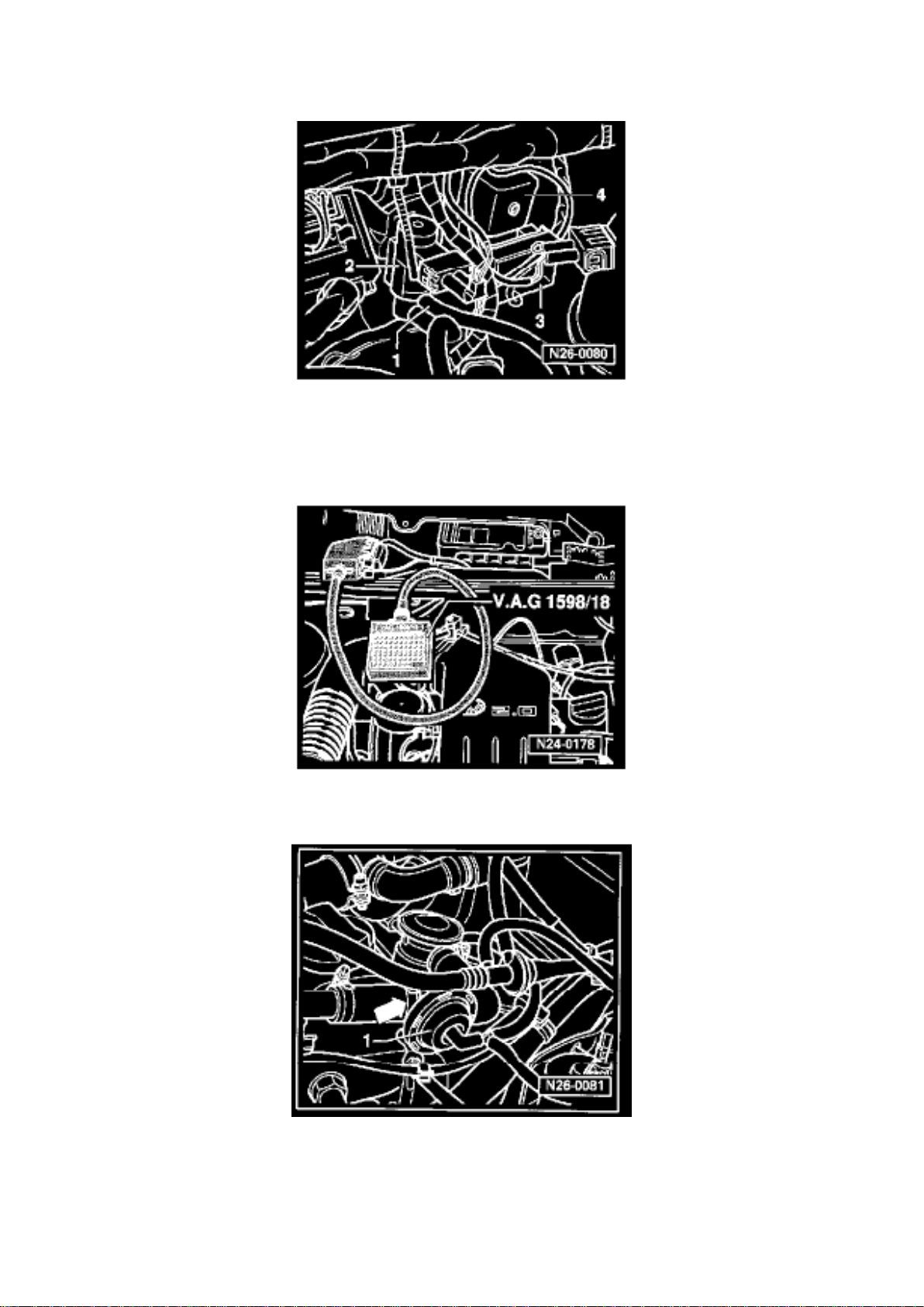
Air Injection: Testing and Inspection Secondary Air Injection Pump Motor, Checking
Page 3

SECONDARY AIR INJECTION PUMP MOTOR, CHECKING
Special tools, testers and auxiliary items
- VAG 1598/18 test box
- VW 1594 connector test kit
- VAG 1527B voltage tester
Test conditions
- Fuse -3- on secondary air injection pump relay J299 -4- OK
Test sequence
- Connect VAG 1598/18 test box to ECM wiring harness.
- Disconnect pressure hose from check valve -1-.
- Connect test box sockets 1 and 50 using adapter cables from VW 1594 connector test kit.
- Secondary air injection pump motor must run and air must exit the connecting hose.
If the motor runs, but no air exits the hose:
- Check hoses and lines.
- If necessary, replace secondary air injection pump motor
If the motor does not run:
- Disconnect 2-pin connector from secondary air injection pump motor V101.
- Connect VAG 1527B voltage tester to 2-pin connector using adapter cables from VAG 1594 test
kit.
Page 4

Page 1184
Page 5

Terminal (circuit):
Page 6

1 - Ignition coil/ignition distributor low voltage (typically used as an Engine Speed (RPM) signal for
the tachometer)
15 - Switched Battery Positive Voltage (B+) from ignition/starter switch
30 - Battery Positive Voltage (B +), hot at all times
31 - Ground (GND)
50 - Starter control; switched B+ from ignition/starter switch
56 - Switched headlight B+ from light switch
58 - Switched parking light, taillight. illumination B+ from light switch
S (SU) - Key In ignition circuit: switched B+ from ignition/starter switch
X - Load reduction circuit; switched B+ from load reduction relay
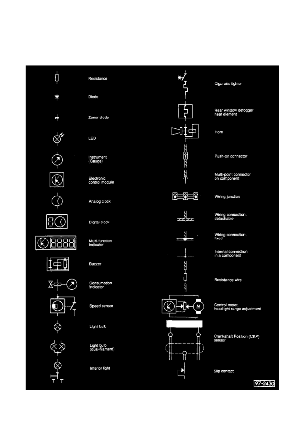
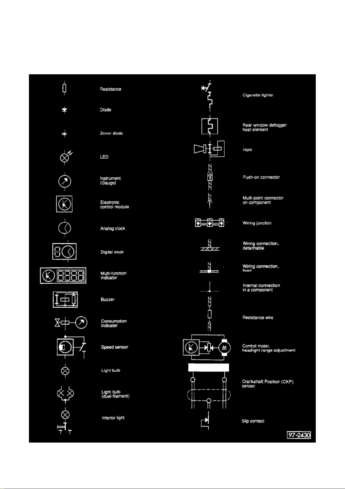
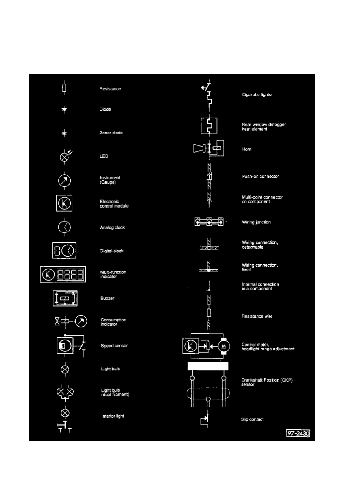
Symbols Used In Wiring Diagrams
Symbols Used in Wiring Diagrams
Page 7

Page 500
Page 8
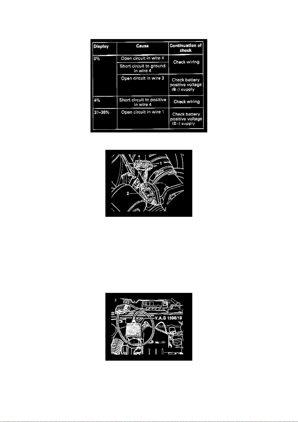
Checking Voltage Supply
Page 9

- Separate 4-pin connector to MAF sensor.
- Connect multimeter to measure voltage at connector terminals 1 and 3.
- Switch ignition on. Specification: Min. 9 volts
- Switch ignition off.
- Reconnect MAF sensor harness connector.
If no voltage is present:
- Check wiring according to wiring diagram.
Checking wiring
- Connect VAG 1598/18 test box to ECM wiring harness.
Page 10

Page 1109
Page 11

- How to Find the Correct Wiring Diagram - How to Read Displayed Page of Wiring Diagram Wiring Diagram Circuit Identification - Symbols Used In Wiring Diagrams - Wire Color Code
Page 12

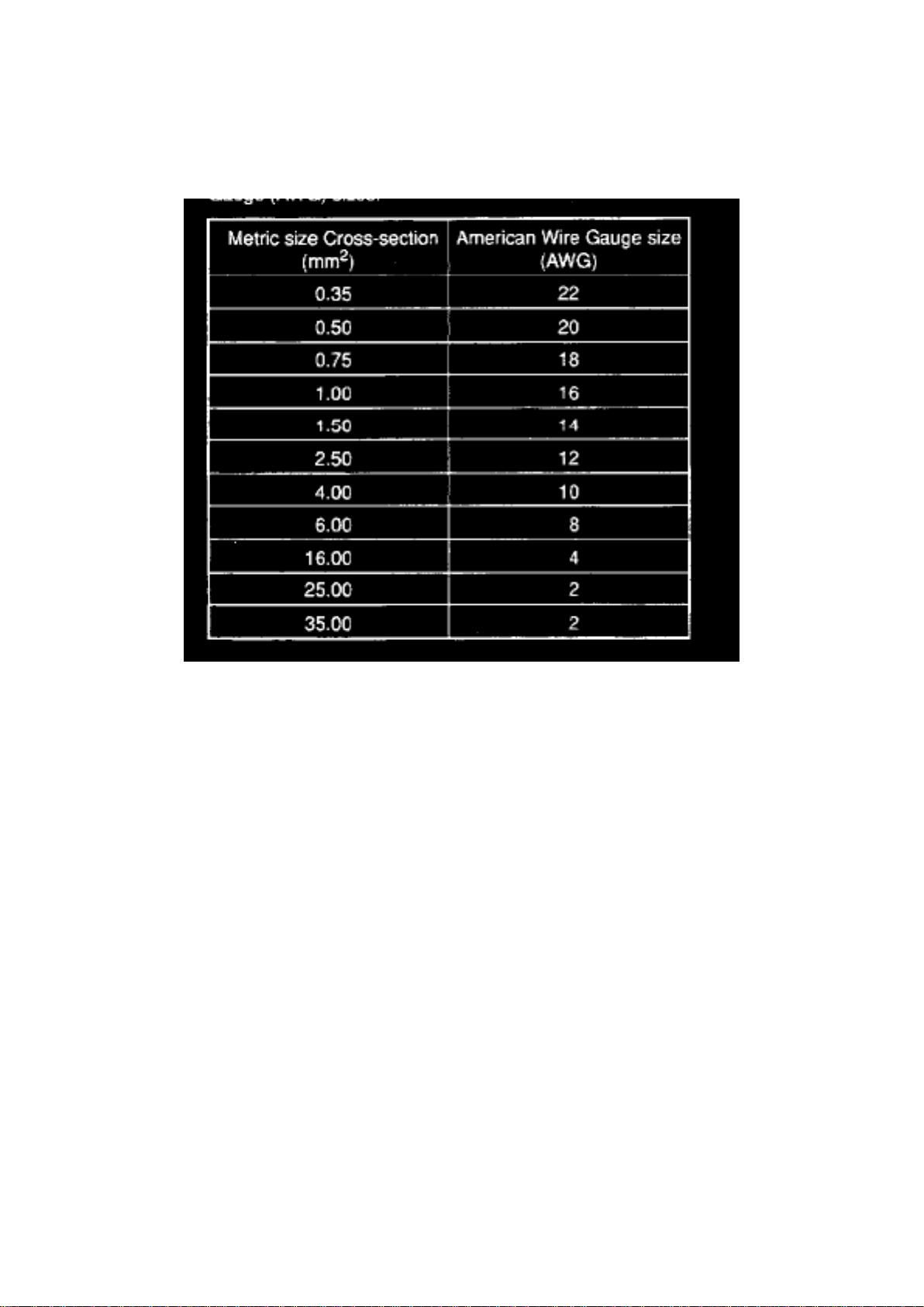
Identification - Wire Size Conversion
How to Find the Correct Wiring Diagram, Important Stuff!
Go to the Index for Track Diagrams under Vehicle : Diagrams : Electrical : Engine Specific - Main
Wiring Diagrams.
Find the system or component you need and click on the hyperlink [shaded blue].
See: Diagrams/Electrical Diagrams/Engine Specific - Main Wiring Diagrams/Index For Track
Diagrams
How to Read Displayed Page of Wiring Diagram, Important Stuff!
Page 13
Page 1545
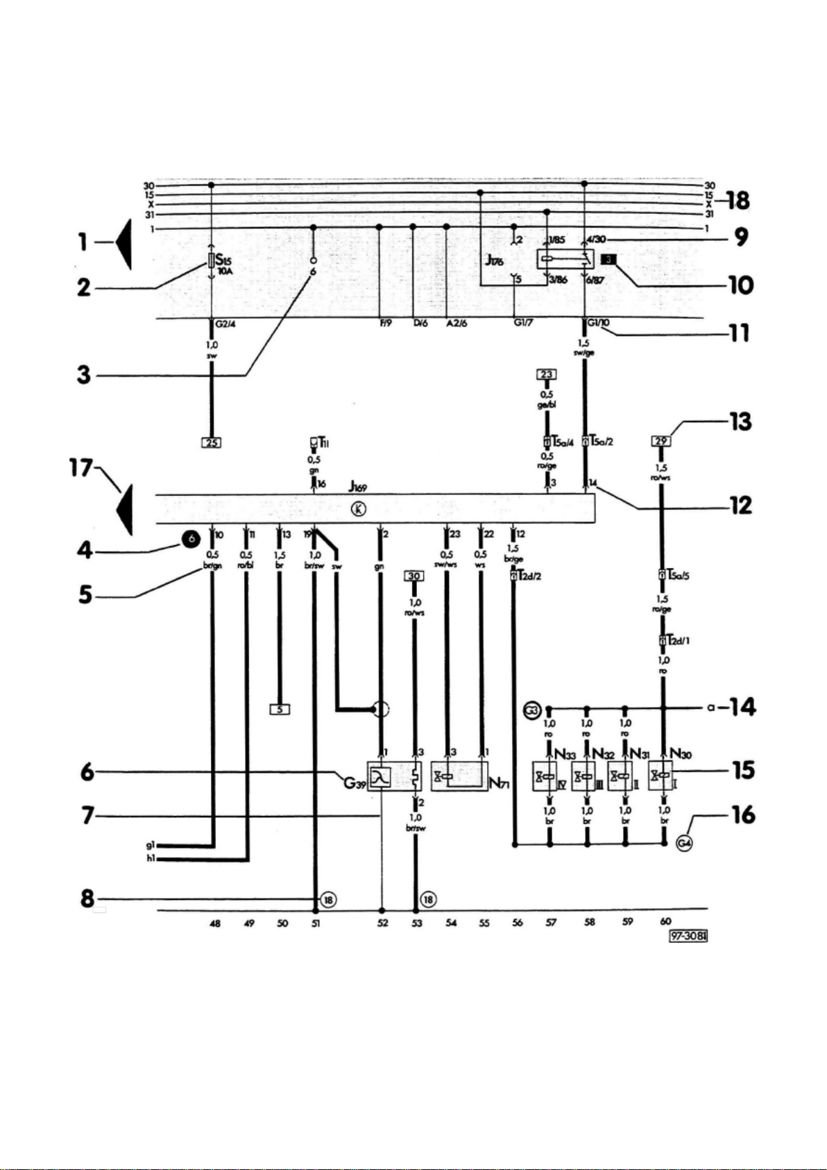
5 - Wire cross-section size (in mm2) and wire colors See chart above for wire size conversion to
American Wire Gauge (AWG). Wire color abbreviations are explained in color code chart on each
page of the wiring diagram.
6 - Component designation (code) Use legend at bottom of page to identify the component code.
7 - Internal connections (thin lines) These connections are not always wires. Internal connections
are current carrying and are listed to allow tracing of current flow inside components and wiring
hamesses.
8 - Wire harness ground connection Locations of ground connections are indicated in the legend.
9 - Relay/control module connectors on fuse/relay panel Shows the individual terminals in a
multi-point connector. Example: 4/30
4 = contact 4 at location [3] on relay panel or relay carrier
30 = terminal 30 (B+) on relay/control module
10 - Relay location number Indicates relay location on fuse/relay panel.
11 - Fuse/relay panel connectors Shows wiring of multi-point or single connectors on fuse/relay
panel.
Example: G1/10 = multi-point connector G1, terminal 10
12 - Terminal designation Designation which appears on actual component and/or terminal number
of a multi-point connector.
Page 14

13 - Wire continuation (current track number) Number in frame indicates current track where wire is
continued.
14 - Continuation of internal connections Letters indicate where connection continues on the
previous and/or next page.
15 - Component symbols (see page IV and V)
16 - Wiring harness wire connection Locations of wire connections are indicated in the legend.
17 - Arrow Indicates component is continued on the previous and/or next page.
18 - Circuit Identification (Fuse/Relay Panel)
1 - Ignition coil/ignition distributor low voltage (typically used as an Engine Speed (RPM) signal for
the tachometer)
15 - Switched Battery Positive Voltage (B+) from ignition/starter switch
30 - Battery Positive Voltage (B+), hot at all times
31 - Ground (GND)
50 - Starter control; switched B+ from ignition/starter switch
56 - Switched headlight B+ from light switch
58 - Switched parking light, taillight. illumination B+ from light switch
S (SU) - Key In ignition circuit: switched B+ from ignition/starter switch X
- Load reduction circuit; switched B+ from load reduction relay
Wiring Diagram Circuit Identification
Wiring Diagram Terminal (circuit) Identification
Several wiring circuits in the vehicle's electrical system are identified with a number or letter
designation. These circuits are identified the same in all wiring diagrams and are most commonly
shown near the top of each page in the fuse/relay panel portion of the wiring diagram. The circuit
designations may also be used to identify switch connector terminals (switch circuits). Following
are the most common numbered/lettered circuits:
Page 15
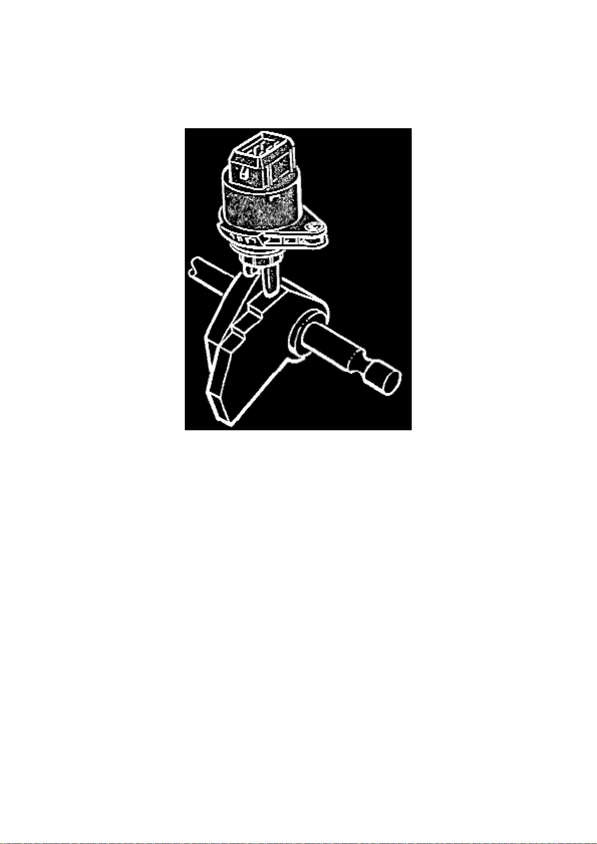
Description and Operation
Transmission Position Switch/Sensor: Description and Operation
Multifunction Switch
Multifunction Switch F125
is located on the gearbox housing is operated by the selector lever and has the following functions:
The automatic transmission selector lever position is monitored by the ECM control unit. When the
selector lever is in a position other than park or neutral, the ECM control unit changes the output
signal to the idle stabilizer valve to compensate for the additional load placed on the engine.
^ Transmitting the selector lever position to the Digimat control unit
^ Switching on the reversing lights
^ Blocking the starter when a driving range is engaged
^ Providing information about the switching on and off of the cruise control system
Page 16
Page 1984
li = lilac
ge = yellow
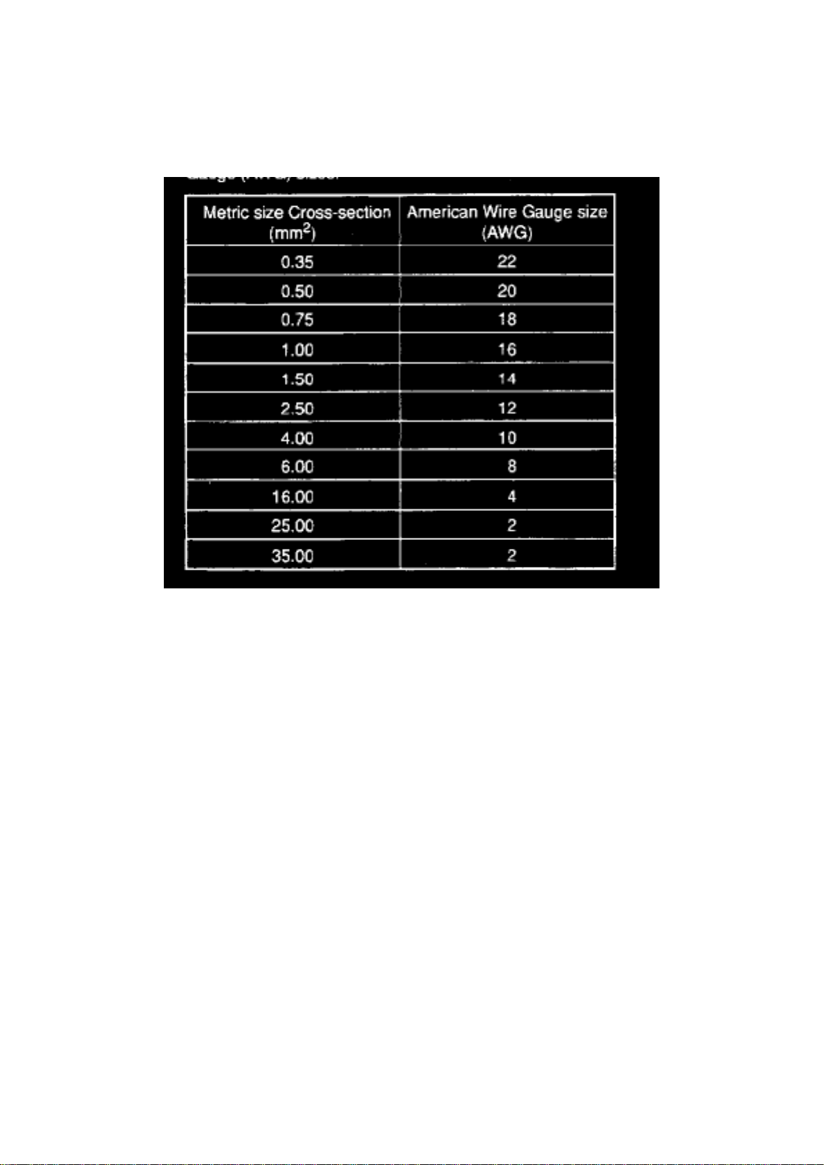
Wire Size Conversion
Wire Size Conversion Chart
Wire cross-section size (in mm2) and wire colors See chart above for wire size conversion to
American Wire Gauge (AWG). Wire color abbreviations are explained in color code chart on each
page of the wiring diagram.
Page 17
Page 612
li = lilac
ge = yellow
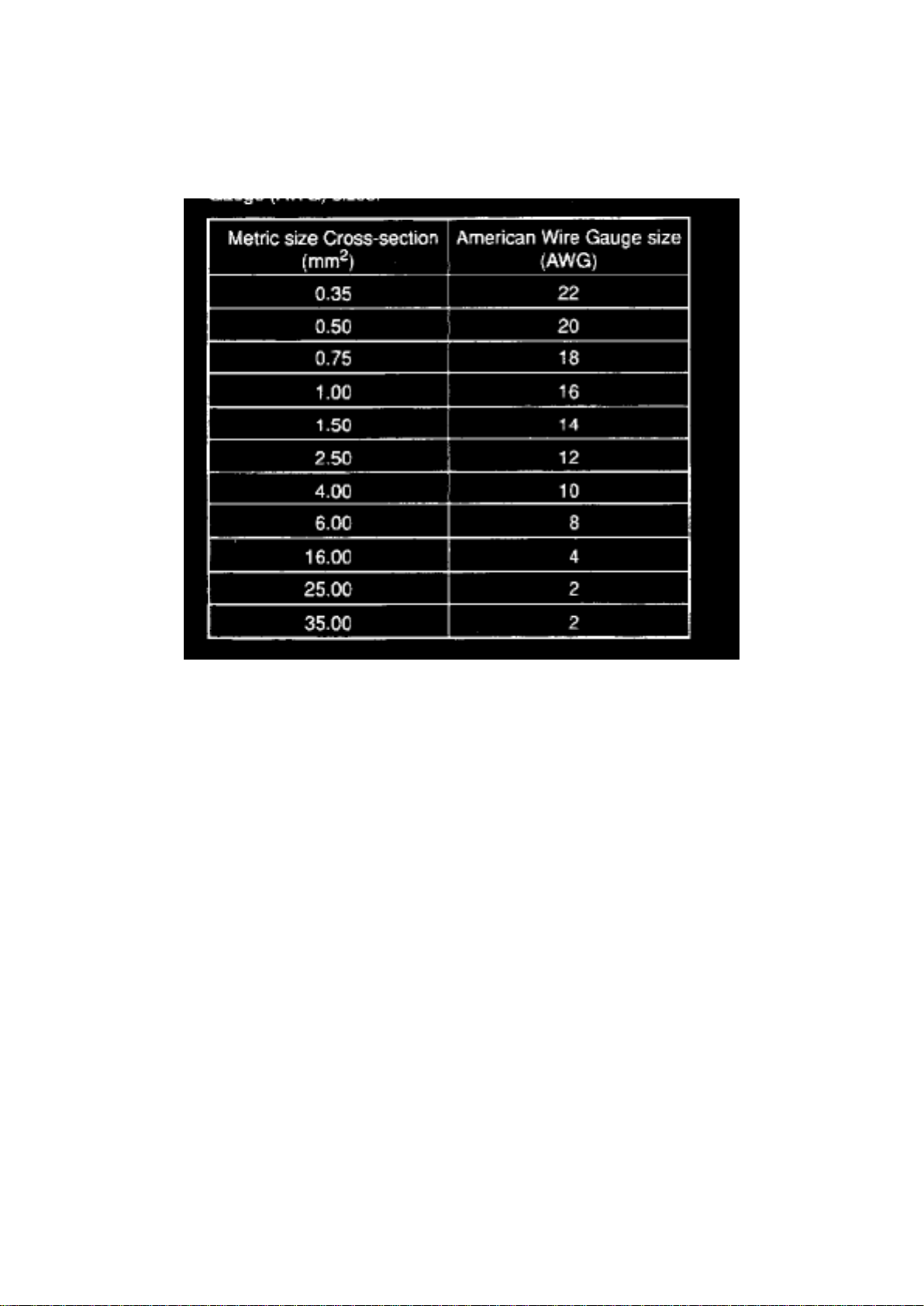
Wire Size Conversion
Wire Size Conversion Chart
Wire cross-section size (in mm2) and wire colors See chart above for wire size conversion to
American Wire Gauge (AWG). Wire color abbreviations are explained in color code chart on each
page of the wiring diagram.
Page 18
Page 350
1 - Arrow Indicates wiring circuit is continued on the previous and/or next page.
2 - Fuse designation For example: S15 = Fuse number 15, 10 amps, in fusel relay panel.
3 - Test points on fuse/relay panel
Page 19

4 - Test points used during troubleshooting. Numbers in black circles may be found in a regular
wiring diagram or in a wiring diagram included with troubleshooting.
Page 20
Page 1081
Engine Mount: Service and Repair Engine Mount Rubber Bushing, Replacing
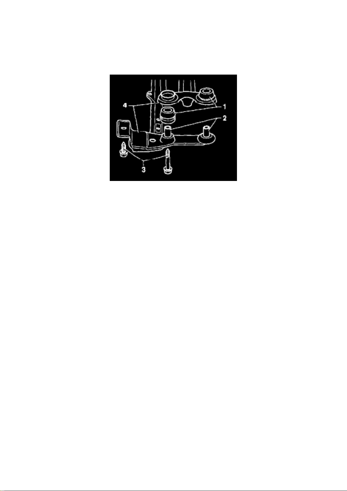
Engine mount rubber bushing, replacing
- Install engine holding fixture 10-222A with supports 10-222A/1.
- Connect engine sling in hook eye on cylinder head (left side) and tighten to lift engine slightly.
- Remove engine mount.
- Pry spacer -2- from rubber mount bushing.
- Remove rubber mount bushing -1-.
Take notice of rubber mount bushing -1- installation position.
- Install new rubber mount bushing.
- Press engine mount spacer into rubber mount bushings.
- Install engine mount -4- and tighten bolts -3-.
Tightening torque: 80 Nm (59 ft lb)
Page 21
Page 649
Page 22

Wire Color Code Identification
Wire Color Code Identification
ws = white
sw = black
ro = red
br = brown
gn = green
bl = blue
gr = grey
Page 23

Page 592
Page 24
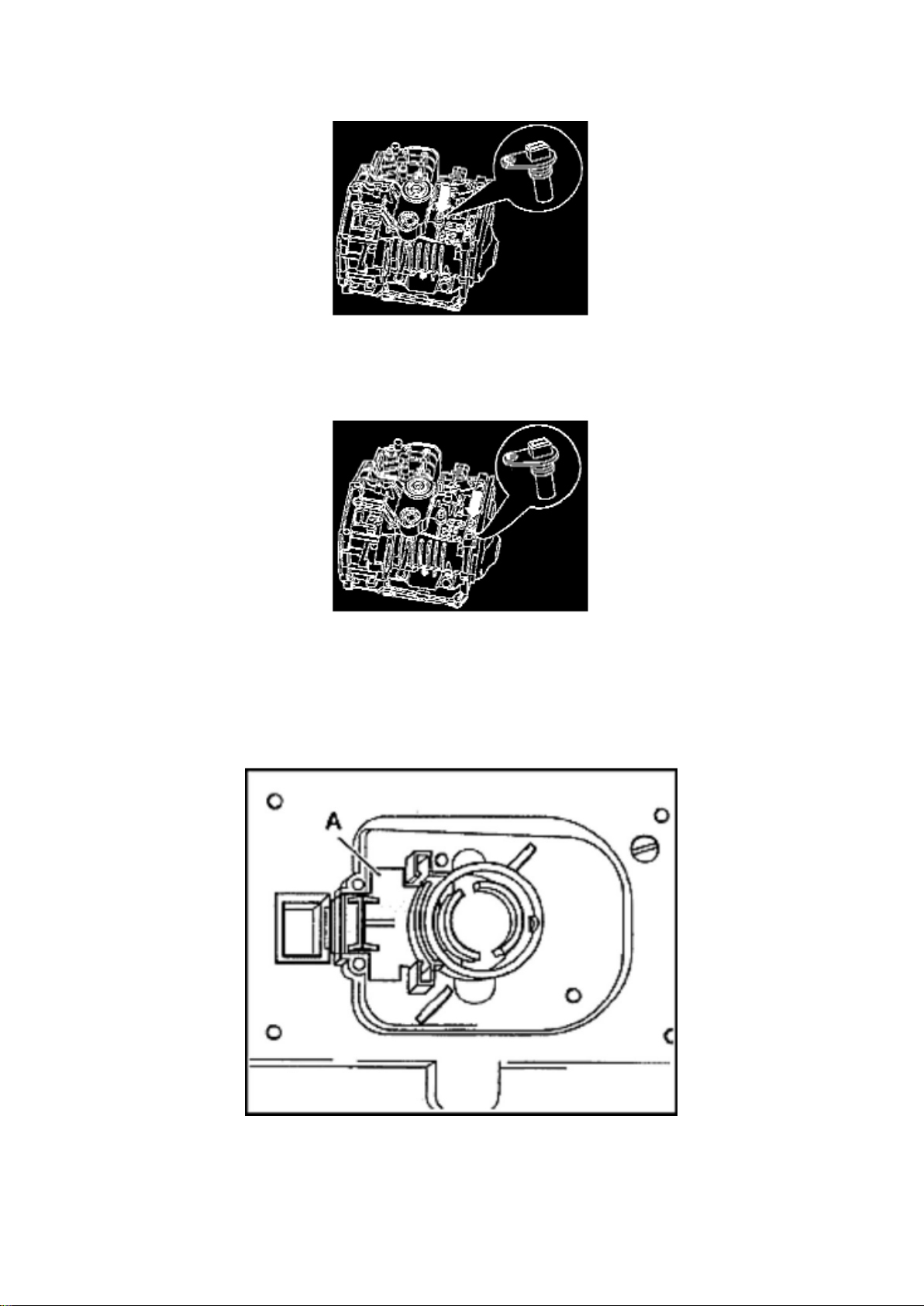
Vehicle Speed Sensor: Locations Automatic Transmission 01M
Page 25

With Electronic Speedometer
Vehicle Speed Sensors
Transmission Vehicle Speed Sensor (VSS) -G38-, location
The Transmission VSS arrow is located on top of the transmission.
Vehicle Speed Sensor (VSS) -G68-, location
The VSS -G68- arrow is located on top of the transmission.
CAUTION: Do not interchange connector T2 for vehicle speed sensors -G38- and -G68With Mechanical Speedometer
Vehicel speed sensor location
The vehicle speed sensor is located on the back of the instrument cluster with the mechanical
speedometer.
Page 26
Page 68
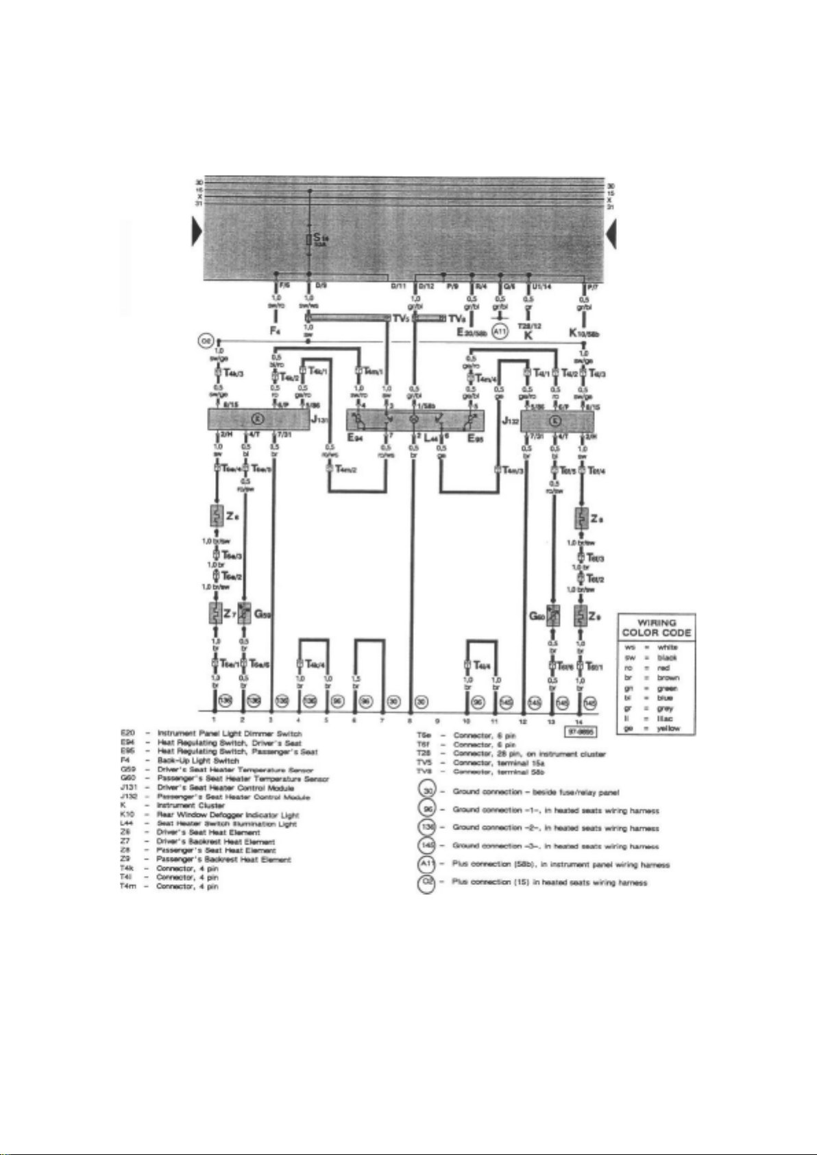
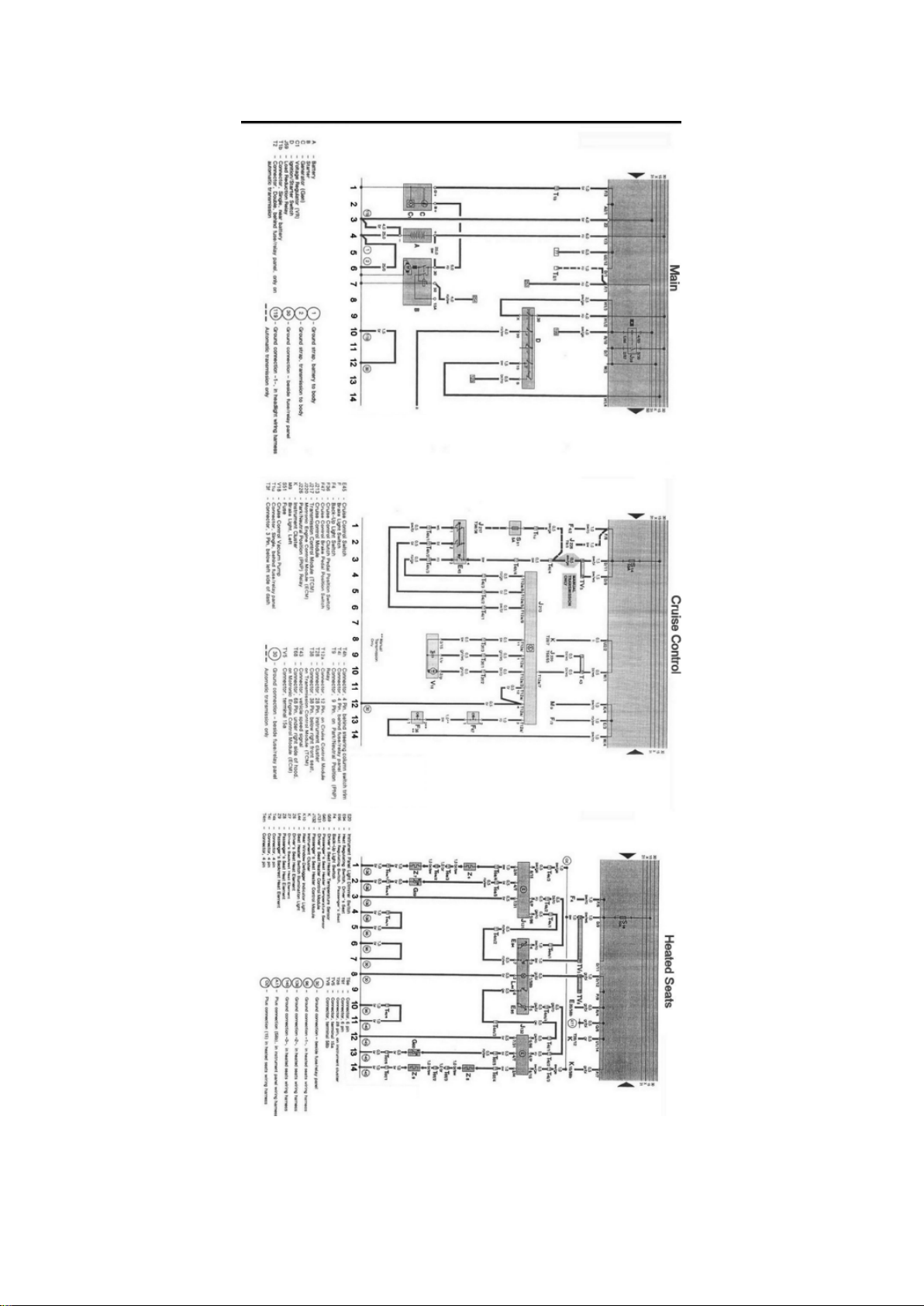
Tracks 1 - 14 from the Main Diagrams Tracks 1 - 14 from the Cruise Control Diagrams Tracks 1 14 from the Heated Seats Diagrams
Don't be confused; this is not a mistake! Furthermore, track numbering schemes do not necessarily
have to be consecutive, and there may appear to be missing tracks. Again this is not a mistake.
Page 27

Additional Caution should be taken when using Optional/Common Equipment wiring diagrams. Do
not try to intermix the "Engine Specific - Main Wiring Diagrams" and Optional/Common Equipment
wiring diagrams. The optional equipment diagrams are self contained, complete, power to ground
diagrams. Components such as the "Fresh Air Blower Motor" found in the Heating and Air
Conditioning diagrams are not wired the same way as the "Fresh Air Blower Motor" found in the
"Engine Specific - Main Wiring Diagrams", which is used for models without Air Conditioning.
"Current Flow Diagrams" or "Track" style wiring diagrams show the powerflow through all wires,
connectors, switches and motors beginning at the top of the page, usually the fuse/relay box, down
the page to "ground" at the bottom. If a particular Current Track does not provide all of the "Power
to Ground" information about a system or component, continuations and splices, etc. will be shown.
See: Diagrams/Diagram Information and Instructions/How to Read Displayed Page of Wiring
Diagram, Important Stuff!
Things you need to know how to use!
Page 28
Page 282
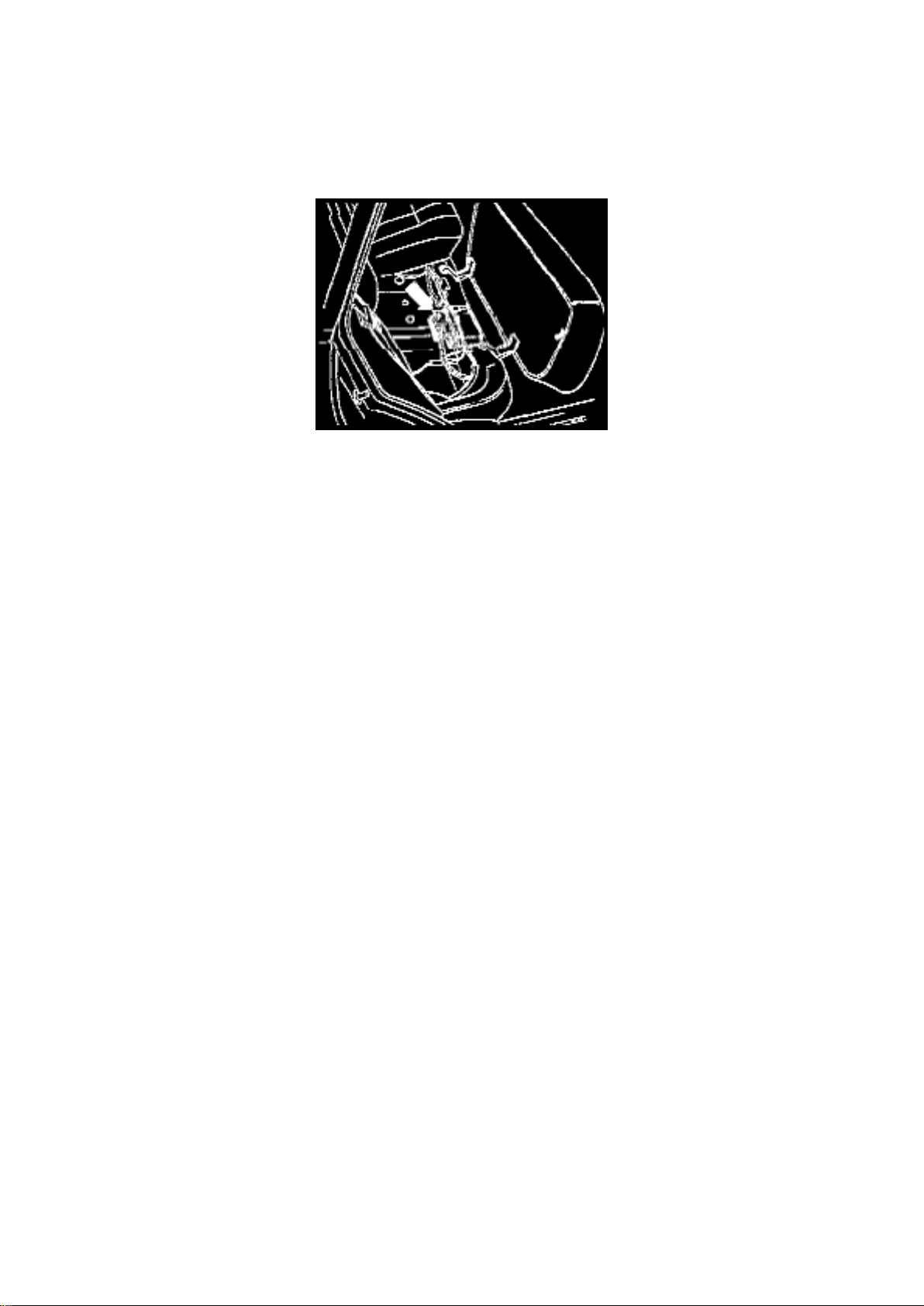
Control Module: Locations 01M Transmission
The Transmission Control Module (TCM) -J217- is located under the rear seat.
Page 29
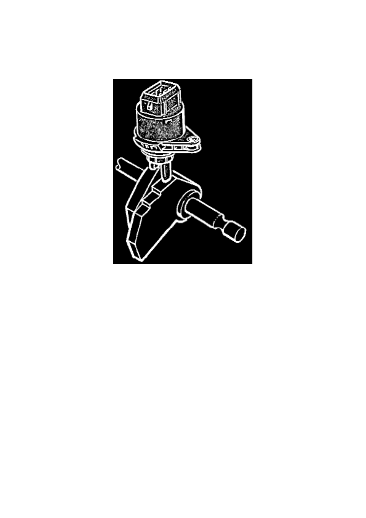
Description and Operation
Transmission Position Switch/Sensor: Description and Operation
Multifunction Switch
Multifunction Switch F125
is located on the gearbox housing is operated by the selector lever and has the following functions:
The automatic transmission selector lever position is monitored by the ECM control unit. When the
selector lever is in a position other than park or neutral, the ECM control unit changes the output
signal to the idle stabilizer valve to compensate for the additional load placed on the engine.
^ Transmitting the selector lever position to the Digimat control unit
^ Switching on the reversing lights
^ Blocking the starter when a driving range is engaged
^ Providing information about the switching on and off of the cruise control system
Page 30
Page 1301
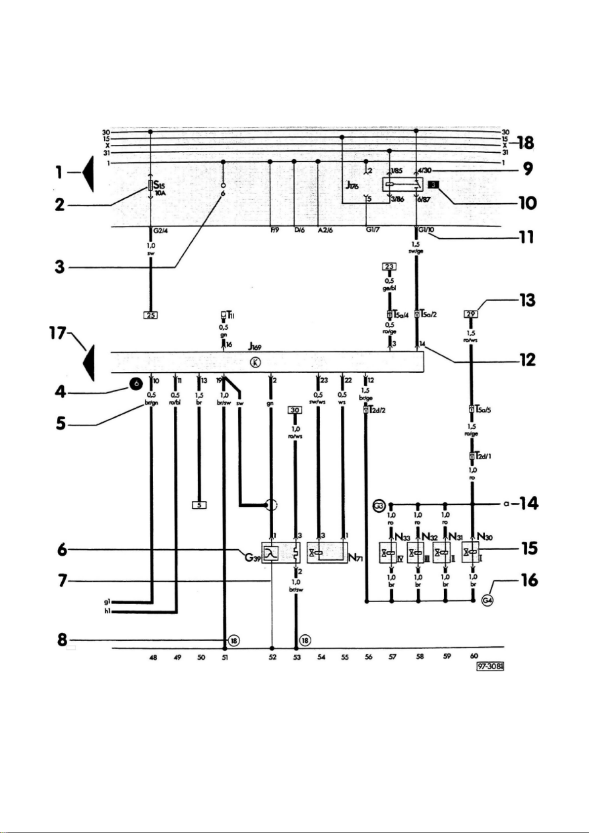
1 - Arrow Indicates wiring circuit is continued on the previous and/or next page.
2 - Fuse designation For example: S15 = Fuse number 15, 10 amps, in fusel relay panel.
3 - Test points on fuse/relay panel
Page 31

4 - Test points used during troubleshooting. Numbers in black circles may be found in a regular
wiring diagram or in a wiring diagram included with troubleshooting.
Page 32
Page 1348
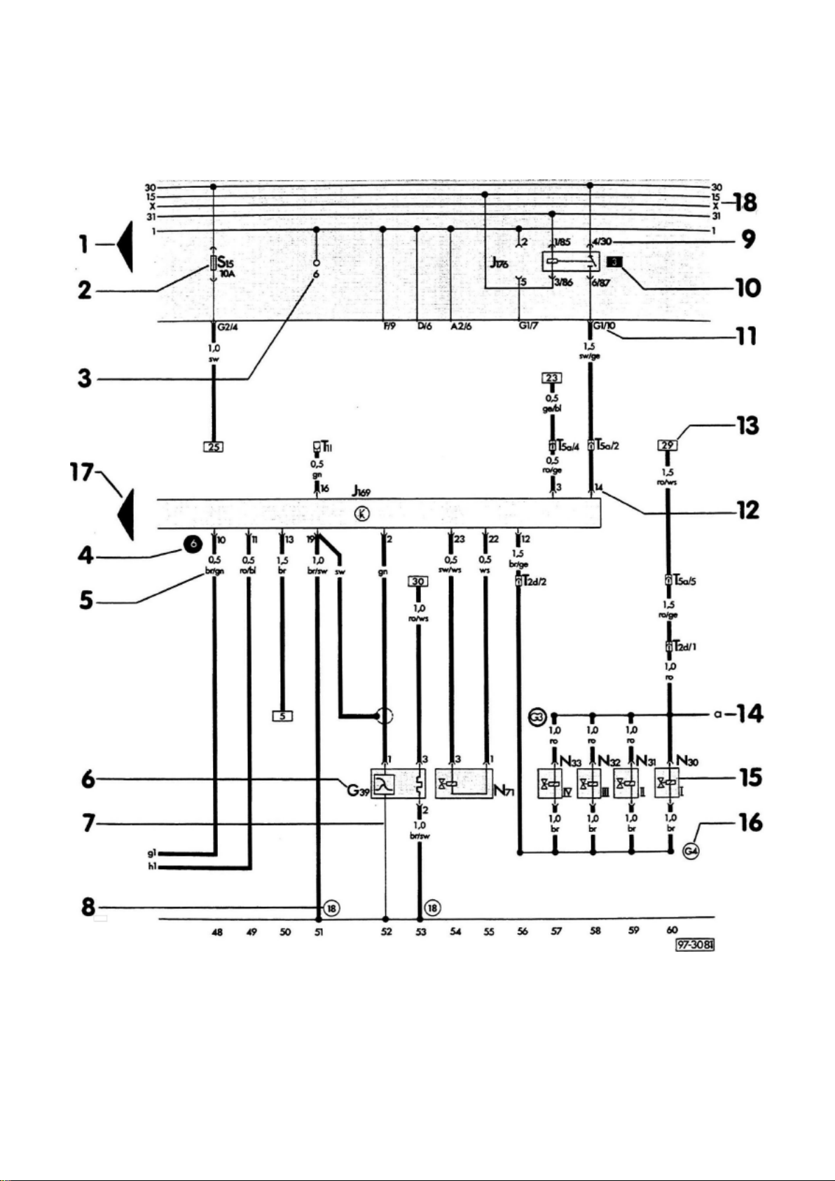
1 - Arrow Indicates wiring circuit is continued on the previous and/or next page.
2 - Fuse designation For example: S15 = Fuse number 15, 10 amps, in fusel relay panel.
3 - Test points on fuse/relay panel
Page 33

4 - Test points used during troubleshooting. Numbers in black circles may be found in a regular
wiring diagram or in a wiring diagram included with troubleshooting.
Page 34
Page 139
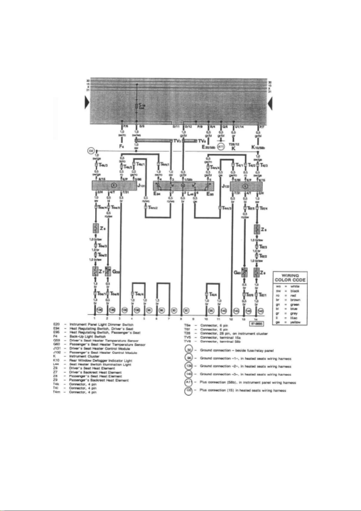
Tracks 1 - 14 from the Main Diagrams Tracks 1 - 14 from the Cruise Control Diagrams Tracks 1 14 from the Heated Seats Diagrams
Don't be confused; this is not a mistake! Furthermore, track numbering schemes do not necessarily
have to be consecutive, and there may appear to be missing tracks. Again this is not a mistake.
Page 35

Additional Caution should be taken when using Optional/Common Equipment wiring diagrams. Do
not try to intermix the "Engine Specific - Main Wiring Diagrams" and Optional/Common Equipment
wiring diagrams. The optional equipment diagrams are self contained, complete, power to ground
diagrams. Components such as the "Fresh Air Blower Motor" found in the Heating and Air
Conditioning diagrams are not wired the same way as the "Fresh Air Blower Motor" found in the
"Engine Specific - Main Wiring Diagrams", which is used for models without Air Conditioning.
"Current Flow Diagrams" or "Track" style wiring diagrams show the powerflow through all wires,
connectors, switches and motors beginning at the top of the page, usually the fuse/relay box, down
the page to "ground" at the bottom. If a particular Current Track does not provide all of the "Power
to Ground" information about a system or component, continuations and splices, etc. will be shown.
See: Diagrams/Diagram Information and Instructions/How to Read Displayed Page of Wiring
Diagram, Important Stuff!
Things you need to know how to use!
Page 36
Page 2235
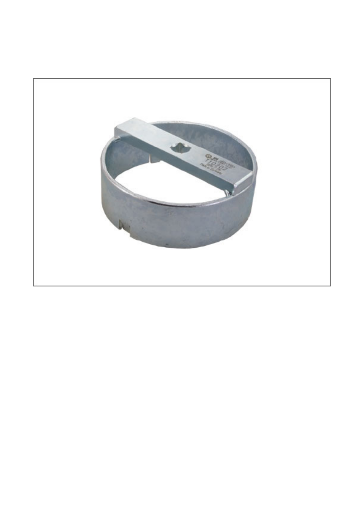
Fuel Tank: Tools and Equipment
Fuel Tank Wrench
AST tool# T 10202
Fuel Tank Wrench used for removing and installing the sealing ring for the fuel tank sender flange.
Comparable/Replaces VW tool number: 3087
- Made in Germany
- Call AST for Pricing
Contact AST for pricing.
Assenmacher Specialty Tools 1-800-525-2943
Page 37

Page 887
Page 38

Engine Oil: Capacity Specifications
Page 39

NOTE: Also see Owners Manual.
CAPACITY
Without oil filter change .......................................................................................................................
................................................. 3.5 liters (3.7 qts) With oil filter change .............................................
................................................................................................................................ 4.0 liters (4.2 qts)
Page 40
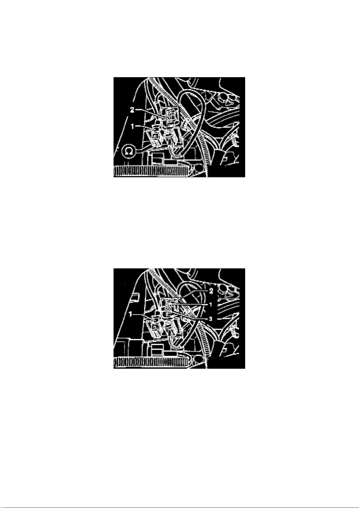
Knock Sensor, Checking
Knock Sensor: Testing and Inspection Knock Sensor, Checking
KNOCK SENSOR, CHECKING
Special tools, testers and auxiliary items
- VAG 1598/18 test box
- Multimeter (Fluke 83 or equivalent)
- VW 1594 connector test kit
Page 41

- Wiring diagram
Test sequence
- Disconnect brown 3-pin harness connector -2- from knock sensor 1 G61 socket -1-,
- Measure resistance between terminals 1 and 2, 1 and 3 and 2 and 3 at knock sensor connector
socket.
Specification: Infinity Ohms (no continuity)
If the specification is attained:
- Connect VAG 1598/18 test box to ECM wiring harness.
- Check wiring between test box and 3-pin connector for open circuit according to wiring diagram. Terminal 1 and test box socket 34
- Terminal 2 and test box socket 33
- Terminal 3 and test box socket 56
- Wire resistance: Max. 1.5 Ohms
- Additionally check wires for short to one another. Terminal 3 and test box socket 34
- Terminal 3 and test box socket 33
- Terminal 2 and test box socket 34
- Specification: Infinity ohm (no continuity)
If no wiring malfunction is detected:
- Loosen knock sensor and tighten again to 20 Nm (15 ft lb).
If the malfunction is still present (stored again in DTC memory):
- Replace knock sensor.
Page 42
Page 2047
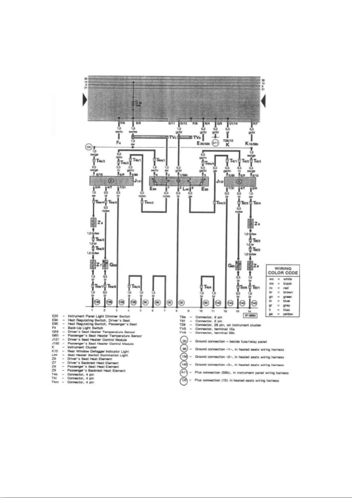
Tracks 1 - 14 from the Main Diagrams Tracks 1 - 14 from the Cruise Control Diagrams Tracks 1 14 from the Heated Seats Diagrams
Don't be confused; this is not a mistake! Furthermore, track numbering schemes do not necessarily
have to be consecutive, and there may appear to be missing tracks. Again this is not a mistake.
Page 43

Additional Caution should be taken when using Optional/Common Equipment wiring diagrams. Do
not try to intermix the "Engine Specific - Main Wiring Diagrams" and Optional/Common Equipment
wiring diagrams. The optional equipment diagrams are self contained, complete, power to ground
diagrams. Components such as the "Fresh Air Blower Motor" found in the Heating and Air
Conditioning diagrams are not wired the same way as the "Fresh Air Blower Motor" found in the
"Engine Specific - Main Wiring Diagrams", which is used for models without Air Conditioning.
"Current Flow Diagrams" or "Track" style wiring diagrams show the powerflow through all wires,
connectors, switches and motors beginning at the top of the page, usually the fuse/relay box, down
the page to "ground" at the bottom. If a particular Current Track does not provide all of the "Power
to Ground" information about a system or component, continuations and splices, etc. will be shown.
See: Diagrams/Diagram Information and Instructions/How to Read Displayed Page of Wiring
Diagram, Important Stuff!
Things you need to know how to use!
Page 44
Page 2572
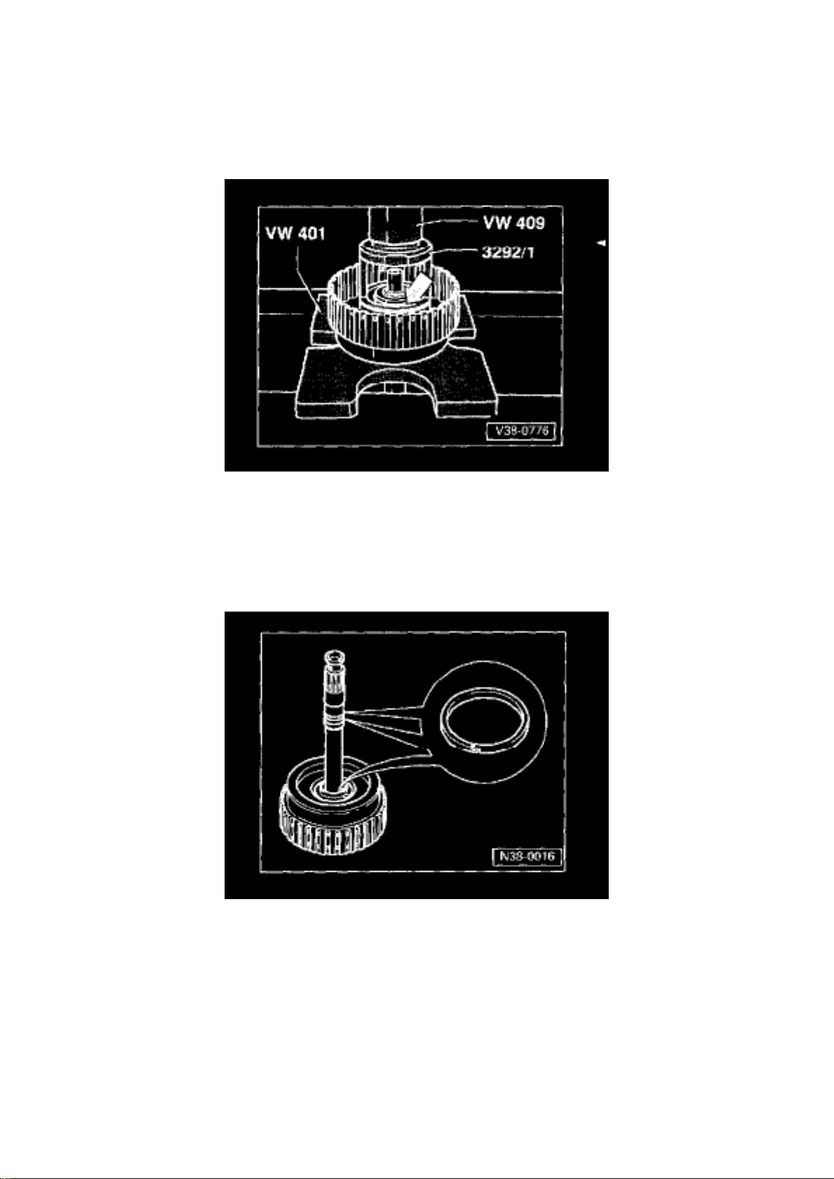
- Sealing lips ore vulcanized to piston - Moisten with ATF before in stalling - Turn piston slightly
while installing
11 - Clutch housing with pump shaft
- Height varies according to number of inner and outer plates
12 - Piston ring
Page 45

- Replace only faulty piston rings - Piston ring is destroyed when removed - Check that ring is
correctly located - Fig. 2 - Installing - Fig. 3
13 - Piston ring
- Replace only faulty piston rings - Unhook ends to remove - Check that ring is correctly located Fig. 2 - Installing - Fig. 3
Fig. 1
Fig. 1 Removing and installing circlip (arrow)
- Press down carefully on piston Lap until the circlip can be installed.
Fig. 2
Fig. 2 Checking that piston rings are correctly located
There is a piston ring installed on the turbine shaft inside the clutch housing (-arrow-).
- Make sure that ends of piston rings are hooked together
Page 46

Specifications
Page 47
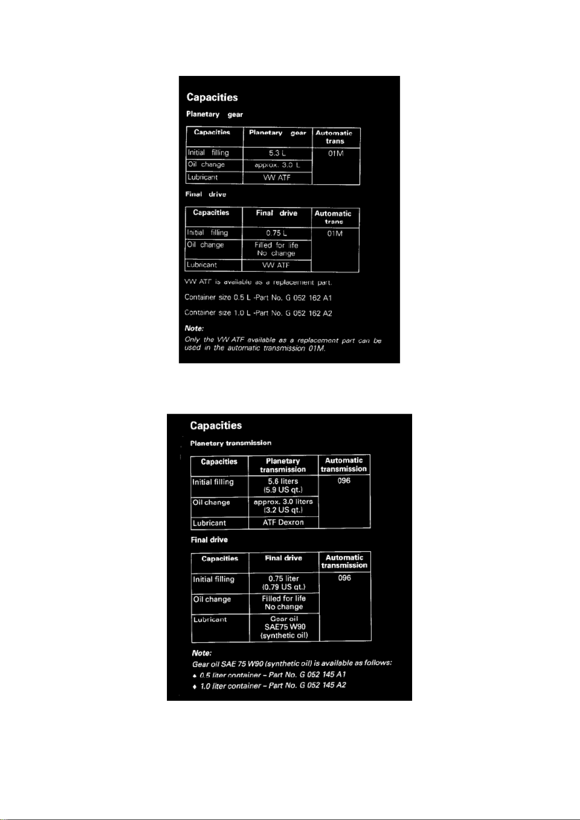
Final Drive Fluid: Specifications
Page 48

- 01M Transmission 4 Speed Automatic 01M
- 096 Transmission -
Page 49
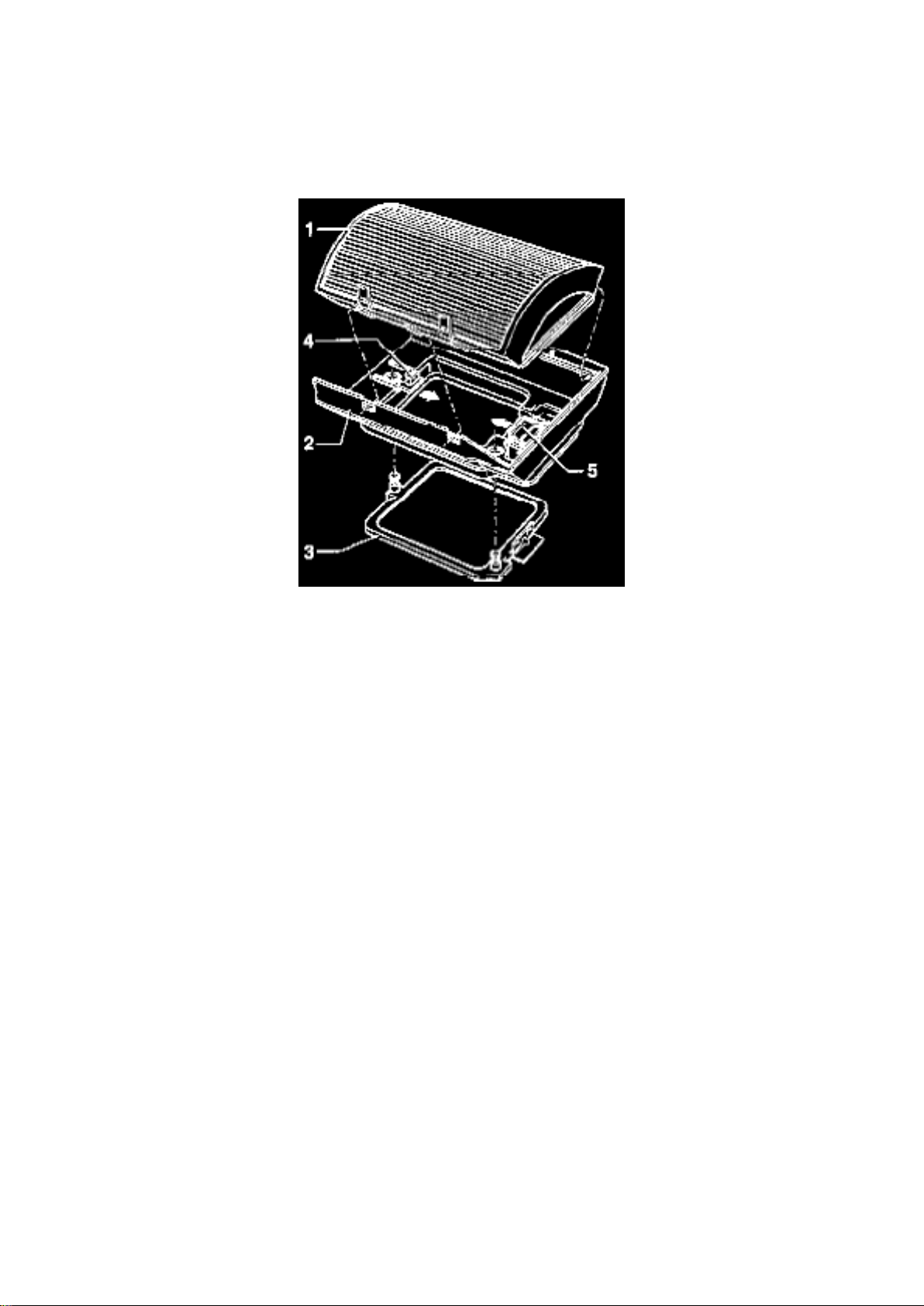
Service and Repair
Cabin Air Filter: Service and Repair
1- Filter element 2- Filter housing 3- Gasket 4- Clip 5- Clip
- Filter element, remove. (Under right plenum cover)
- Press clips -4- and -5- in direction of arrow and remove filter housing.
Page 50
Page 1396
Page 51

Page 2371
Page 52
Page 53

Page 1771
Page 54
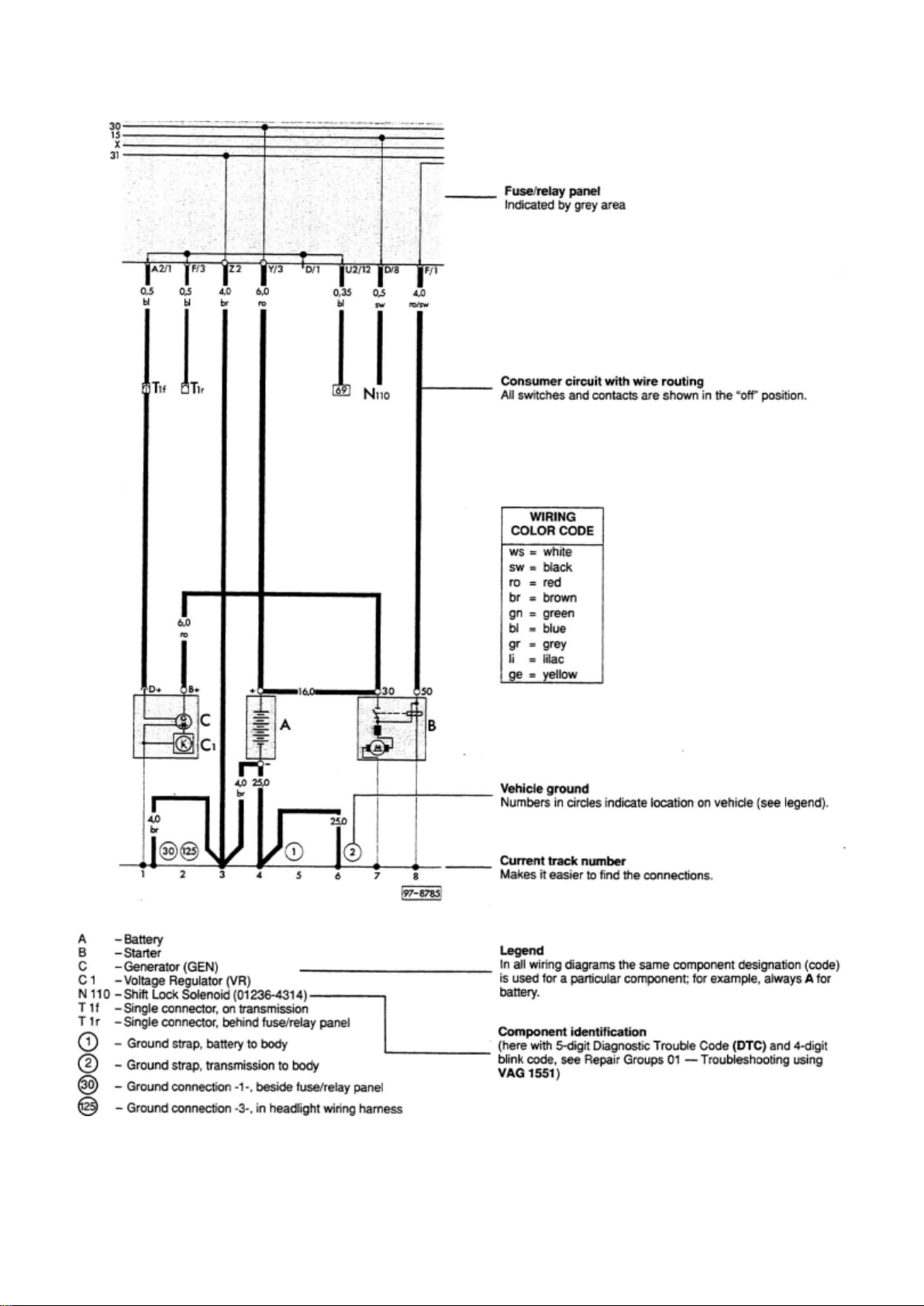
Wiring Diagram Layout
Page 55

How To Read Wiring Diagrams
Page 56
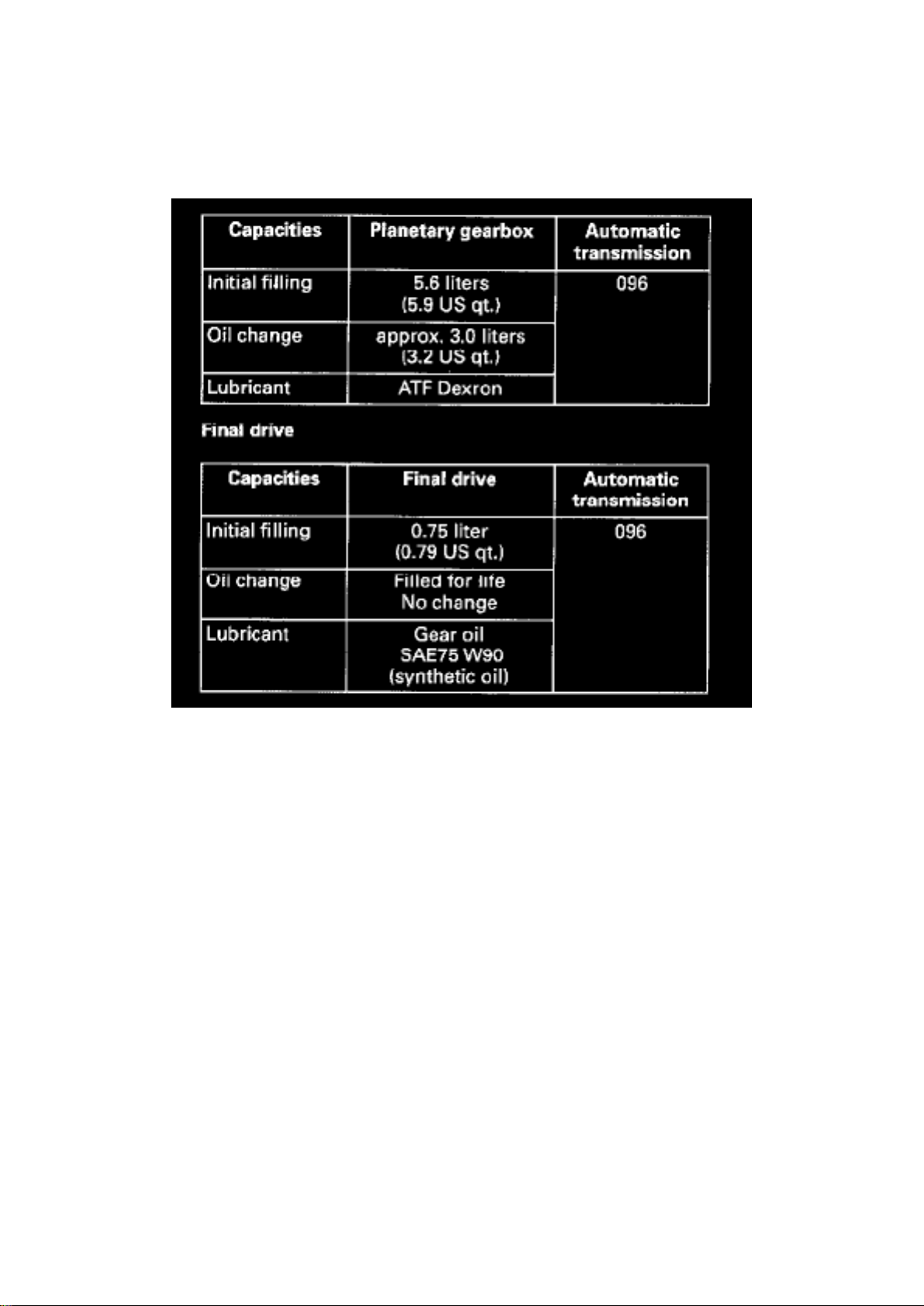
096 Transmission
Fluid - A/T: Specifications 096 Transmission
Capacities
- 096 Transmission Planetary gearbox
Note:
Gear oil SAE 75 W90 (synthetic oil) is available as follows:
- 0.5 liter container - Part No. G 052 145 Al - 1.0 liter container - Part No. G 052 745 A2
Page 57

Page 644
Page 58

- How to Find the Correct Wiring Diagram - How to Read Displayed Page of Wiring Diagram Wiring Diagram Circuit Identification - Symbols Used In Wiring Diagrams - Wire Color Code
Page 59

Identification - Wire Size Conversion
How to Find the Correct Wiring Diagram, Important Stuff!
Go to the Index for Track Diagrams under Vehicle : Diagrams : Electrical : Engine Specific - Main
Wiring Diagrams.
Find the system or component you need and click on the hyperlink [shaded blue].
See: Diagrams/Electrical Diagrams/Engine Specific - Main Wiring Diagrams/Index For Track
Diagrams
How to Read Displayed Page of Wiring Diagram, Important Stuff!
Page 60

Page 180
Page 61

9 - Seat Belt Warning System Relay (4)
Page 62

9 - Radio/Parking Light Warning Buzzer (36)
10 - Fog Light Relay (53)
11 - Dual Horn Relay (53)
12 - Fuel Pump (FP) Relay (167)
12 - Glow Plug Relay (104)
Relay Location Above Fuse/Relay Panel:
- Power Window Circuit Breaker 30 A
- Alarm System Control Module Fuse 10 A
- Luggage Compartment Socket Fuse 20 A
- Power Seat Fuse 20 A
Auxiliary Relay Panel Below Instrument Panel, Left:
- Heated Oxygen Sensor (HO2S) Relay (53)
- ABS Relay (79)
- ABS Hydraulic Pump Relay (179)
- Electronic Differential Lock Shut-Off Relay (179)
- Starting interlock and Back-Up Light Relay (150)
- Automatic Glow Time Control Module (134)
- Shut-Off Relay-A/C (129)
- ABS Hydraulic Pump Fuse 30 A
- ABS Valves Fuse 30 A
- Cruise Control Fuse 5 A
Auxiliary Relay Panel Below Console, Center:
- Cruise Control, Control Module
Page 63
Page 932
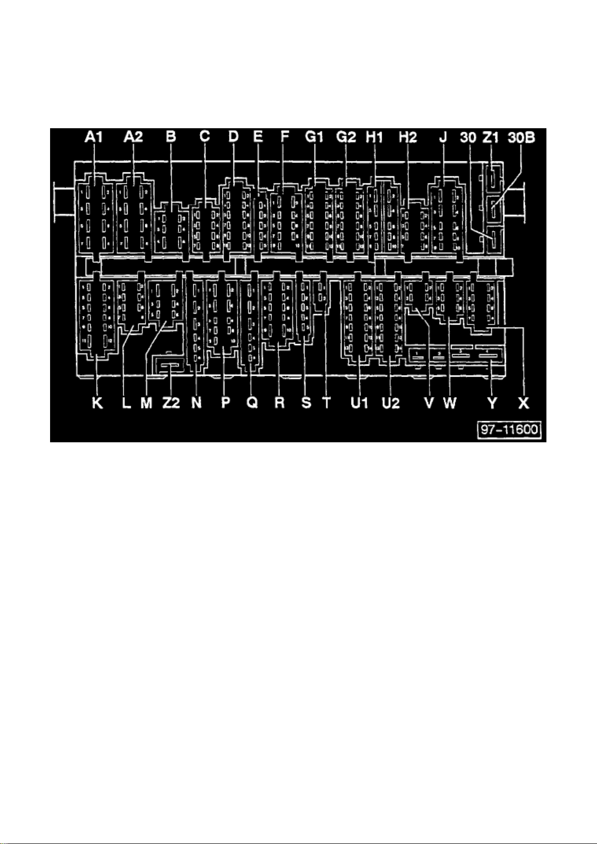
Relay Box: Connector Locations
Multiple Connector Arrangement
A1 - Headlight wiring harness (yellow), 8-Pin A2 - Headlight wiring harness (yellow), 8-Pin B -
Headlight washer system wiring harness (green), 6-Pin C - Headlight wiring harness (yellow), 8-Pin
D - Optional equipment wiring harness (green), 12-Pin E
- Instruments wiring harness (green), 5-Pin
F - Engine compartment wiring harness (white), 9-Pin
G1 - Engine compartment wiring harness (white), 12-Pin G2 - Engine compartment wiring harness
(white), 12-Pin H1 - Steering column switch wiring harness (red), 10-Pin H2 - Steering column
switch wiring harness (red), 8-Pin J
- Steering column switch wiring harness (red),10-Pin
K - Rear wiring harness (black), 12-Pin L
- Rear wiring harness (black), 7-Pin
M - Rear wiring harness (black), 6-Pin N - A/C wiring harness (green), 6-Pin P
- Rear window defogger/fog light switch wiring harness (blue), 9-Pin
Q - Instruments wiring harness (blue), 6-Pin R - Light switch wiring harness (blue), 10-Pin S
Page 64

- Wiper motor wiring harness (white), 5-Pin
T - Double Connector (green)
U1 - Instrument cluster wiring harness (blue), 1-Pin U2 - Instrument cluster wiring harness (blue),
1-Pin V - Steering column wiring harness (green), 4-Pin W - Optional equipment wiring harness
(green), 6-Pin X - Warning lamps (trailer towing, anti-lock brake system) wiring harness (green),
8-Pin Y - Single Connector, terminal 30 Z1 - Single Connector Z2 - Single Connector, terminal 31,
battery-minus 30 - Single Connector, terminal 30 30B- Single Connector*
Page 65
Page 2296
Page 66

Wire Color Code Identification
Wire Color Code Identification
ws = white
sw = black
ro = red
br = brown
gn = green
bl = blue
gr = grey
Page 67
Page 1372
Page 68

Wire Color Code Identification
Wire Color Code Identification
ws = white
sw = black
ro = red
br = brown
gn = green
bl = blue
gr = grey
Page 69

Page 625
Page 70

Throttle Position Sensor: Testing and Inspection Transmission Control Module and TPS Matching
Page 71

TRANSMISSION CONTROL MODULE AND THROTTLE POSITION SENSOR MATCHING
NOTE: On automatic transmission vehicles, the TCM J217 and the TP sensor G69 must be
matched to one another after the following work has been completed.
- Replacement of TCM
- Removal and installation of throttle position sensor
- Replacement of throttle valve housing (throttle body)
Special tools, testers and auxiliary items
- VAG 1551 Scan Tool (ST) with VAG 1551/3 adapter cable
Matching
- Use VAG 1551 scan tool to bring system to basic setting (function 04).
Page 72

Page 444
Page 73
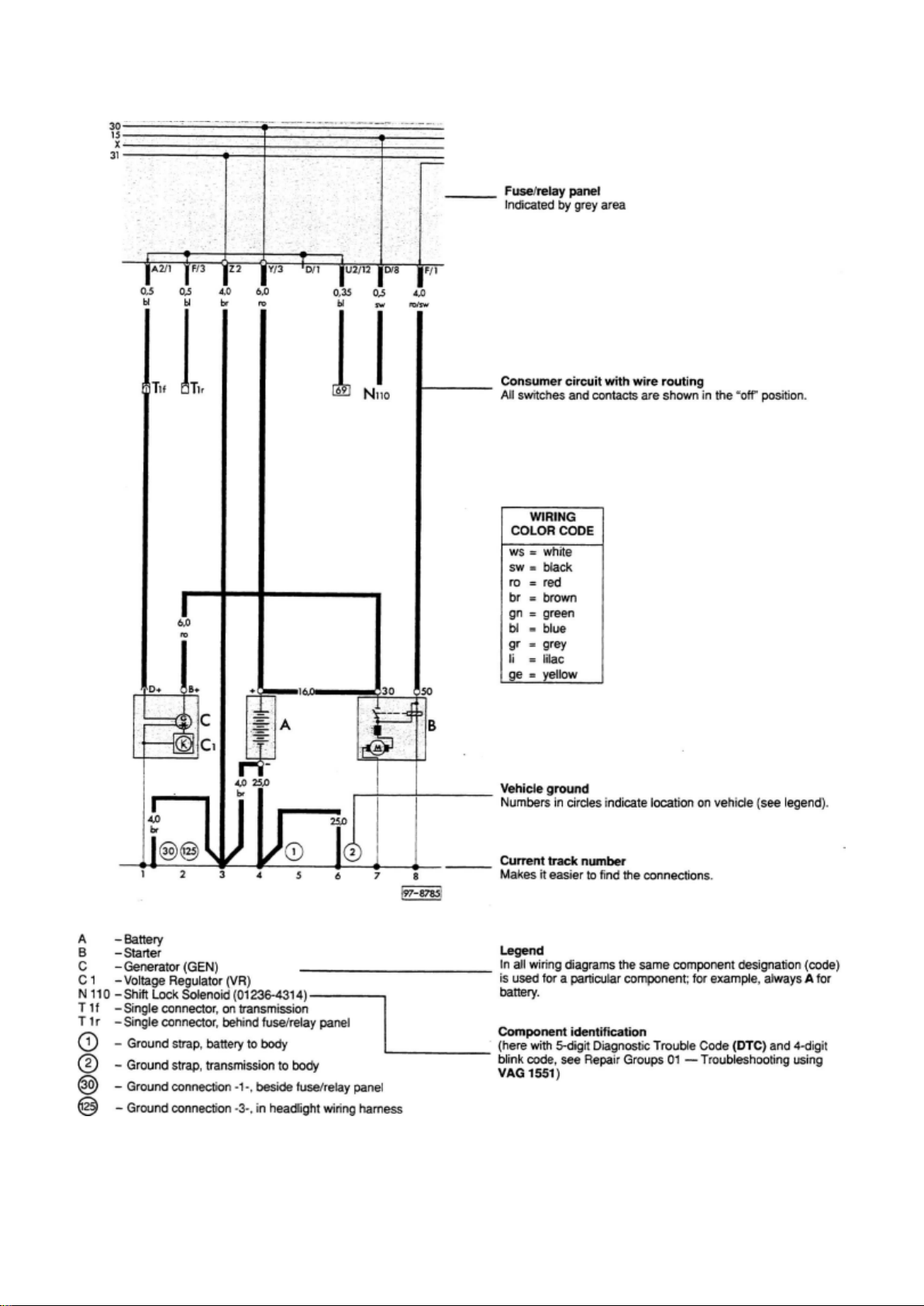
Wiring Diagram Layout
Page 74

How To Read Wiring Diagrams
Page 75
Page 2152
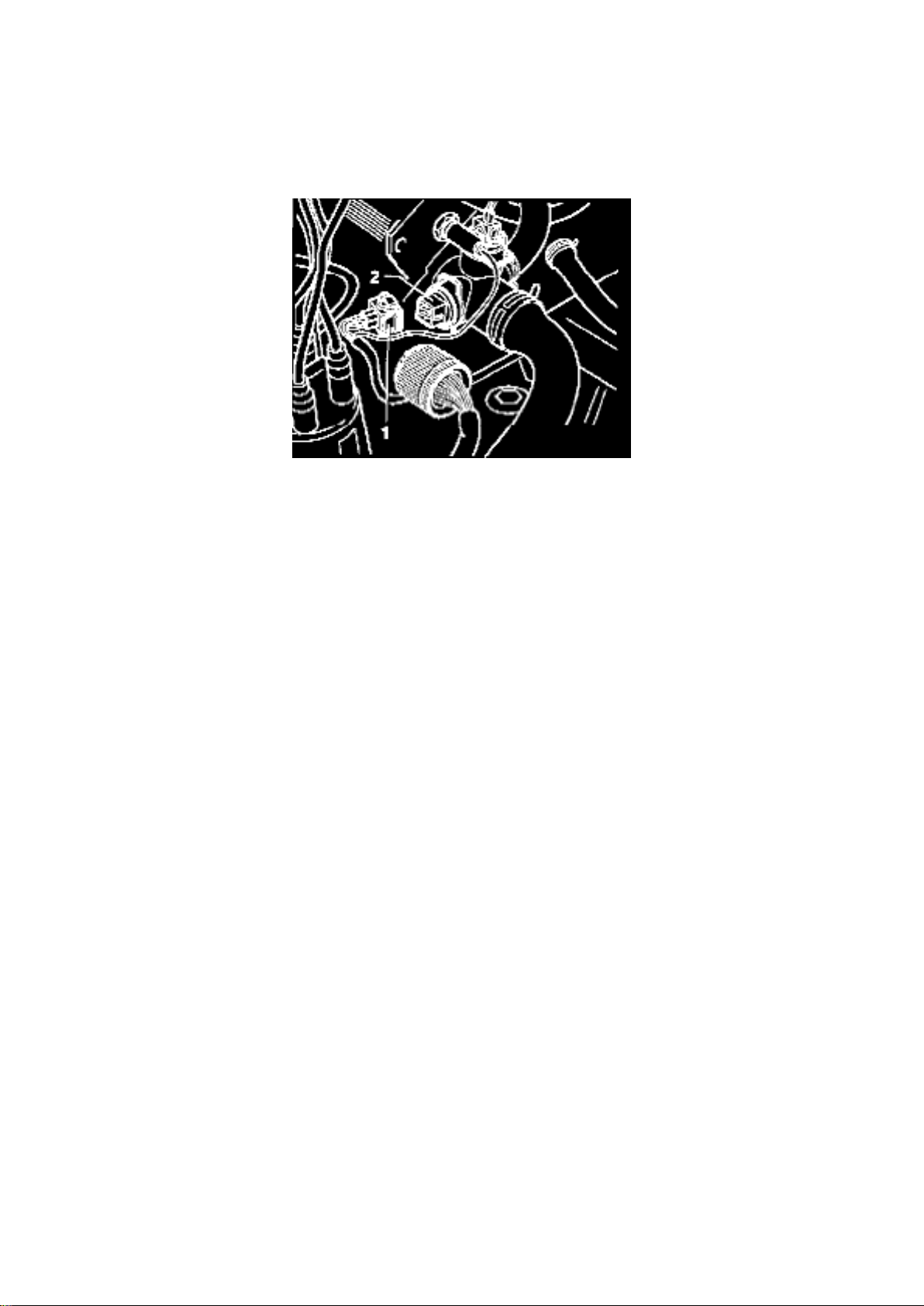
- Disconnect harness connector -1- from engine coolant temperature sensor -2-.
- Duty cycle must increase, then drop again to original value.
NOTE: Test can only be repeated after the DTC memory has been erased.
- Reconnect engine coolant temperature sensor connector.
- Press -> button.
- Press buttons -0- and -2- to select "Check DTC Memory" function 02.
- Press -Q- button to confirm input.
- Press -> button until all malfunctions still stored have been displayed.
Indicated on display
Rapid data transfer HELP
Select function XX
- Press buttons -0- and -5- to select "Erase DTC Memory" function 05.
- Press -Q- button to confirm input.
- Press -> button.
- Press buttons -0- and -6- to select 'End Output" function 06.
- Press -Q- button to confirm input.
Page 76
Page 2582
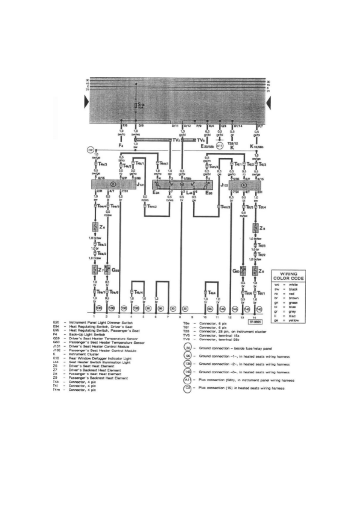
Tracks 1 - 14 from the Main Diagrams Tracks 1 - 14 from the Cruise Control Diagrams Tracks 1 14 from the Heated Seats Diagrams
Don't be confused; this is not a mistake! Furthermore, track numbering schemes do not necessarily
have to be consecutive, and there may appear to be missing tracks. Again this is not a mistake.
Page 77

Additional Caution should be taken when using Optional/Common Equipment wiring diagrams. Do
not try to intermix the "Engine Specific - Main Wiring Diagrams" and Optional/Common Equipment
wiring diagrams. The optional equipment diagrams are self contained, complete, power to ground
diagrams. Components such as the "Fresh Air Blower Motor" found in the Heating and Air
Conditioning diagrams are not wired the same way as the "Fresh Air Blower Motor" found in the
"Engine Specific - Main Wiring Diagrams", which is used for models without Air Conditioning.
"Current Flow Diagrams" or "Track" style wiring diagrams show the powerflow through all wires,
connectors, switches and motors beginning at the top of the page, usually the fuse/relay box, down
the page to "ground" at the bottom. If a particular Current Track does not provide all of the "Power
to Ground" information about a system or component, continuations and splices, etc. will be shown.
See: Diagrams/Diagram Information and Instructions/How to Read Displayed Page of Wiring
Diagram, Important Stuff!
Things you need to know how to use!
Page 78

Engine Speed Sensor, Checking
Page 79
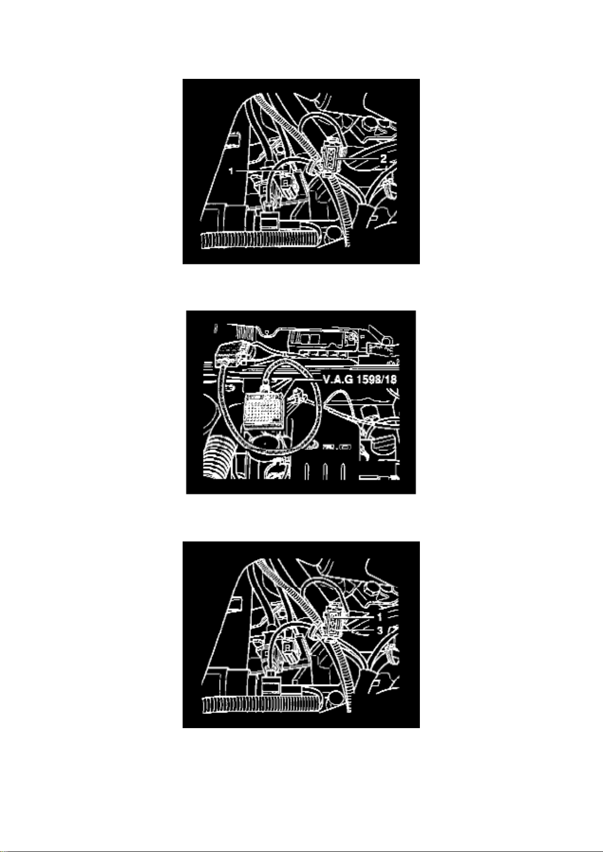
Engine Speed Sensor: Testing and Inspection Engine Speed Sensor, Checking
Page 80

ENGINE SPEED SENSOR, CHECKING
Special Tools, Testers And Auxiliary Items
- VAG 1598/18 test box
- Multimeter (Fluke 83 or equivalent)
- VW 1594 connector test kit
- Wiring diagram
Test Sequence
- Disconnect 3-pin harness connector from sensor -1-.
- Connect VAG 1598/18 test box to ECM wiring harness.
- Check wiring for open circuits between test box and 3-pin connector -1-, according to wiring
diagram. -
Terminal 1 and test box socket 67
- Terminal 2 and test box socket 68
- Terminal 3 and test box socket 56
- Wire resistance: Max. 1.5 Ohms
- Additionally check wires for short to one another. Terminal 1 and test box socket 68
- Terminal 1 and test box socket 56
- Terminal 2 and test box socket 56
- Specification: Infinity Ohms (no continuity)
Page 81

Page 1578
Page 82

Terminal (circuit):
Page 83

1 - Ignition coil/ignition distributor low voltage (typically used as an Engine Speed (RPM) signal for
the tachometer)
15 - Switched Battery Positive Voltage (B+) from ignition/starter switch
30 - Battery Positive Voltage (B +), hot at all times
31 - Ground (GND)
50 - Starter control; switched B+ from ignition/starter switch
56 - Switched headlight B+ from light switch
58 - Switched parking light, taillight. illumination B+ from light switch
S (SU) - Key In ignition circuit: switched B+ from ignition/starter switch
X - Load reduction circuit; switched B+ from load reduction relay
Symbols Used In Wiring Diagrams
Symbols Used in Wiring Diagrams
Page 84

Page 1299
Page 85

- How to Find the Correct Wiring Diagram - How to Read Displayed Page of Wiring Diagram Wiring Diagram Circuit Identification - Symbols Used In Wiring Diagrams - Wire Color Code
Page 86

Identification - Wire Size Conversion
How to Find the Correct Wiring Diagram, Important Stuff!
Go to the Index for Track Diagrams under Vehicle : Diagrams : Electrical : Engine Specific - Main
Wiring Diagrams.
Find the system or component you need and click on the hyperlink [shaded blue].
See: Diagrams/Electrical Diagrams/Engine Specific - Main Wiring Diagrams/Index For Track
Diagrams
How to Read Displayed Page of Wiring Diagram, Important Stuff!
Page 87
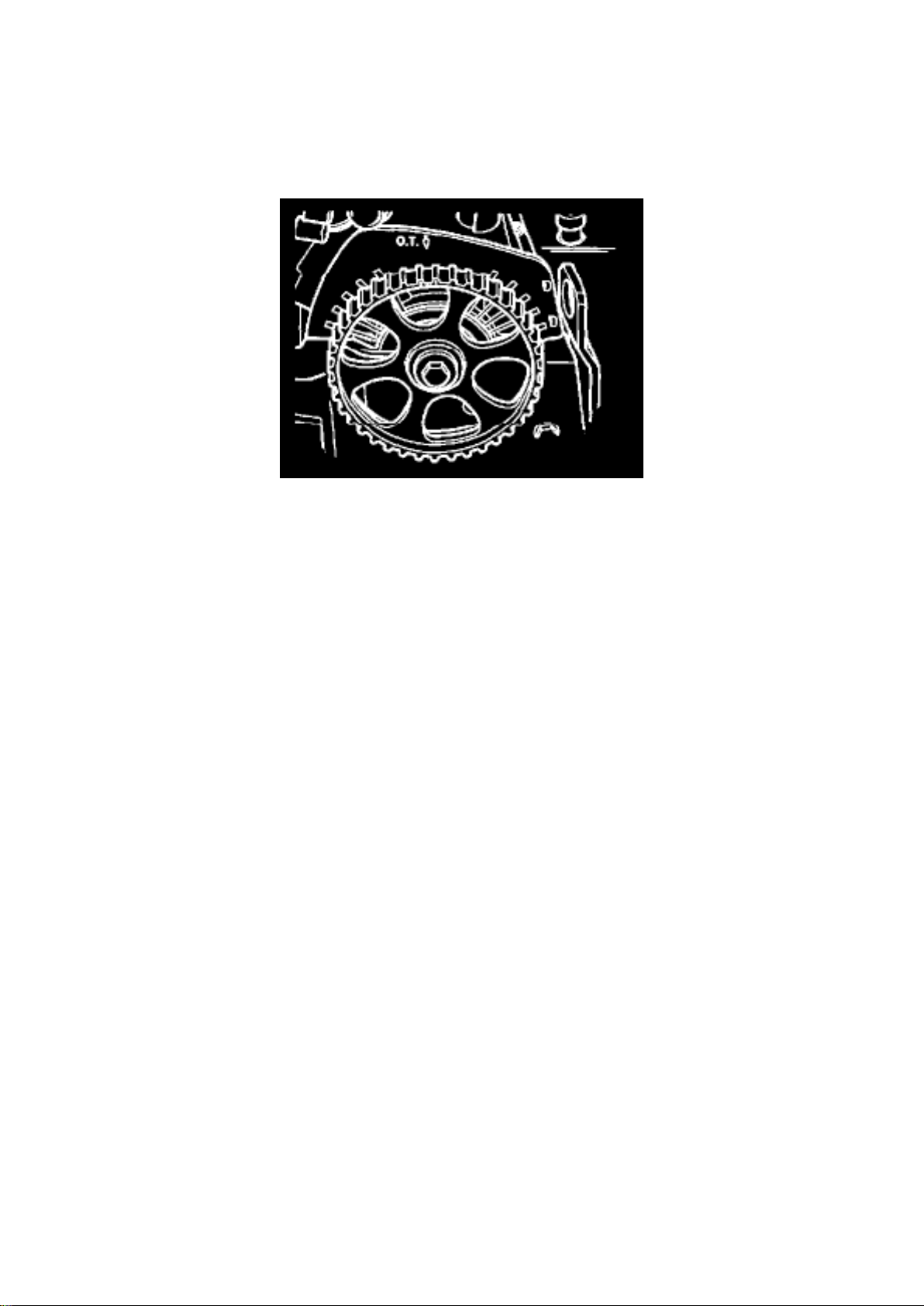
Timing Belt: Removal and Replacement
Toothed drive belt, removing and installing
(Adjusting valve timing)
Page 803
See Caution! and Notes under Installation
Special tools, testers and auxiliary items ^
Ribbed belt installation tool 3299
^ Pin wrench Matra V159
^ Torque wrench VAG 1331(5-50 Nm)
Removing
- Remove ribbed drive belt.
- Remove tensioner for ribbed belt.
- Remove crankshaft vibration damper and pulley.
- Remove coolant pump pulley.
- Remove upper and lower parts of drive belt guard.
- Mark running direction on toothed drive belt.
- Loosen tensioner and remove toothed belt.
Installing
Note: ^
For repairs that require the toothed belt to be removed, carry out the toothed belt adjustment as
follows.
Page 88

- Align marking on camshaft sprocket with marking on drive belt guard.
CAUTION! ^
Before turning the camshaft, make sure that the pistons are NOT at Top Dead Center (TDC). With
the belt removed, there is danger of damage from valve and piston interference.
- Install drive belt on crankshaft drive belt sprocket and on intermediate shaft drive belt sprocket
(note running direction when re-installing a used belt.)
Note: ^
Disregard marking on intermediate shaft drive belt sprocket.
- Install lower drive belt guard.
- Install coolant pump pulley.
- Install crankshaft vibration damper and pulley (note installation position, holes are offset).
- Turn crankshaft to place Cyl. 1 at TDC.
Page 89

Page 2555
Page 90
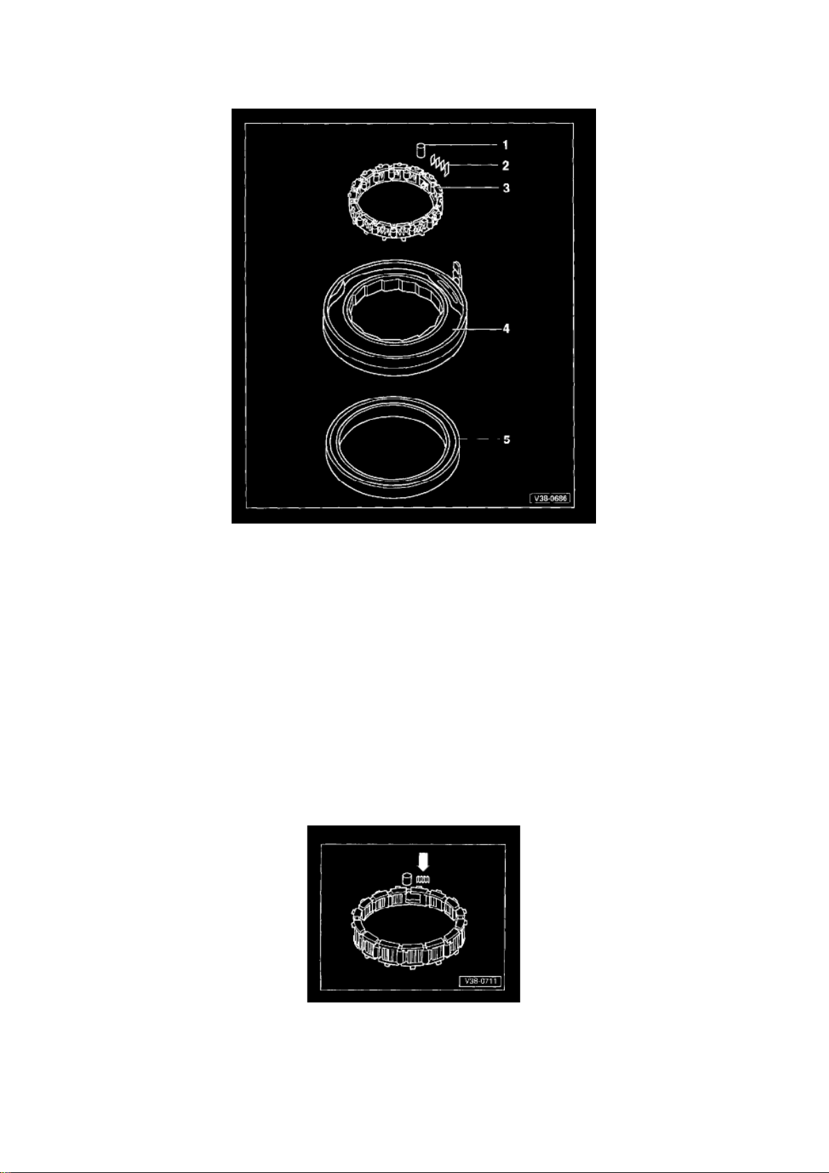
Disassembling and Assembling
Page 91

1 - Rollers
- Installing - Fig. 1
2 - Springs
- Installing - Fig. 1
3 - Cage
- Installing - Fig. 2 - Securing - Fig. 3
4 - Outer ring
5 - Piston
- Sealing lips are vulcanized to piston - Moisten sealing lips with ATF before installing - Turn piston
slightly while installing - Installed position - Fig. 4
Fig. 1
Fig. 1 Installing rollers and springs
Page 92
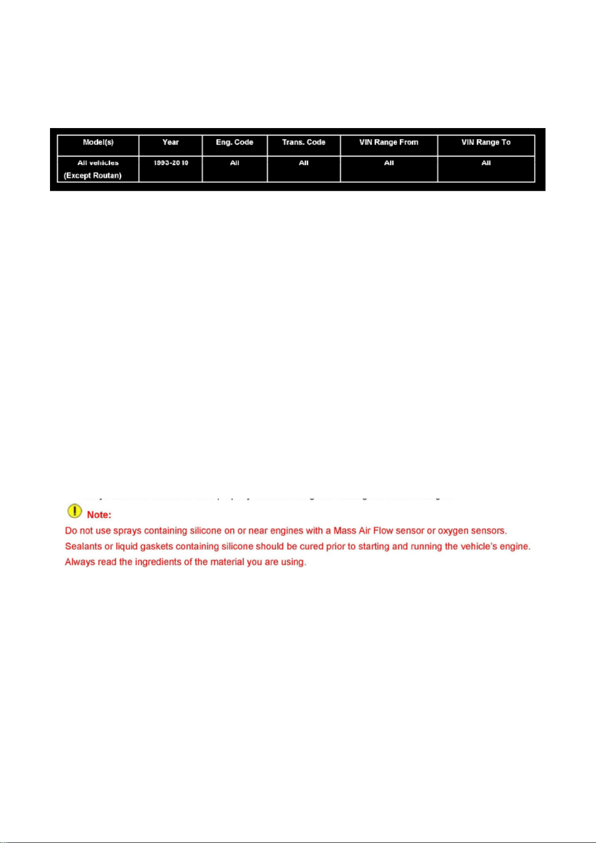
Engine Controls - Silicone Sealer/Lubricant Precautions
Air Flow Meter/Sensor: Technical Service Bulletins Engine Controls - Silicone Sealer/Lubricant
Precautions
00 08 04
Aug. 18, 2008
2002412 Supersedes T.B. Group 00 number 07 01 dated Jan. 19, 2007 due to removal of Routan
applicability.
Vehicle Information
Condition
Sealants, Liquid Gaskets and Lubricants Containing Silicone
Page 93

Technical Background
Damage to Mass Air Flow (MAF) sensors and Oxygen sensors may result from use of sealants,
liquid gaskets, or lubricants containing silicone.
Production Solution
N/A
Service
Many detailing products contain silicone.
If vehicle engine is running when spraying products which contain silicone (tire dressing, exterior
and interior trim cleaner / protectants), silicone may be drawn into the intake system and can
contaminate the MAF sensor and/or oxygen sensors.
^ Do not use sprays containing silicone on or near running engines with a Mass Air Flow sensor or
Oxygen sensors.
In addition, if using sealants or liquid gaskets containing silicone on or near the engine of a vehicle
with a MAF sensor or oxygen sensors:
^ Always allow the silicone to cure properly before starting and running the vehicle's engine.
Warranty
Information only.
Required Parts and Tools
No Special Tools required.
No Special Parts required.
Additional Information
All part and service references provided in this Technical Bulletin are subject to change and/or
removal. Always check with your Parts Dept. and Repair Manuals for the latest information.
Page 94

Page 171
Page 95

Terminal (circuit):
Page 96

1 - Ignition coil/ignition distributor low voltage (typically used as an Engine Speed (RPM) signal for
the tachometer)
15 - Switched Battery Positive Voltage (B+) from ignition/starter switch
30 - Battery Positive Voltage (B +), hot at all times
31 - Ground (GND)
50 - Starter control; switched B+ from ignition/starter switch
56 - Switched headlight B+ from light switch
58 - Switched parking light, taillight. illumination B+ from light switch
S (SU) - Key In ignition circuit: switched B+ from ignition/starter switch
X - Load reduction circuit; switched B+ from load reduction relay
Symbols Used In Wiring Diagrams
Symbols Used in Wiring Diagrams
Page 97
Page 153
- Fuel consumed
From This data the average speed and the average fuel consumption are calculated and stored. It
the trip is continued within two hrs of switching off the ignition, the new values are included in the
calculation.
In position 2 of multi-function indicator mode select switch E86 the contents of the total trip memory
can be displayed. The following data from any number of single trips is collected:
- Driving time (up to 100 hrs)
- Distance driven (up to 10,000 km/miles)
- Fuel consumed (1,000 liters/gallons)
From this data the average speed and consumption for all single trips are calculated and stored. If
one of the given maximum memory capacities is exceeded, the memory is cancelled and the
calculations start over once again. Unlike the single trip memory, the total trip memory is not
cancelled after switching the ignition off for two hours.
Cancelling the Memories
Both memories can be cancelled separately with the ignition on. To cancel memories, slide
multi-function indicator memory switch E109 fully left (for memory 1) or fully right (for memory 2)
into position 0 and hold longer than 1 sec. If battery is disconnected, then both memories are
cancelled automatically.
Setting the Time
To set the time there are two buttons on the left below the engine coolant temperature (ECM)
gauge G3. The upper button (h) is for the hours and the lower one (min) for the minutes. Pressing
the appropriate button briefly will advance the time one hour or minutes. With button depressed,
hours or minutes will advance continuously.
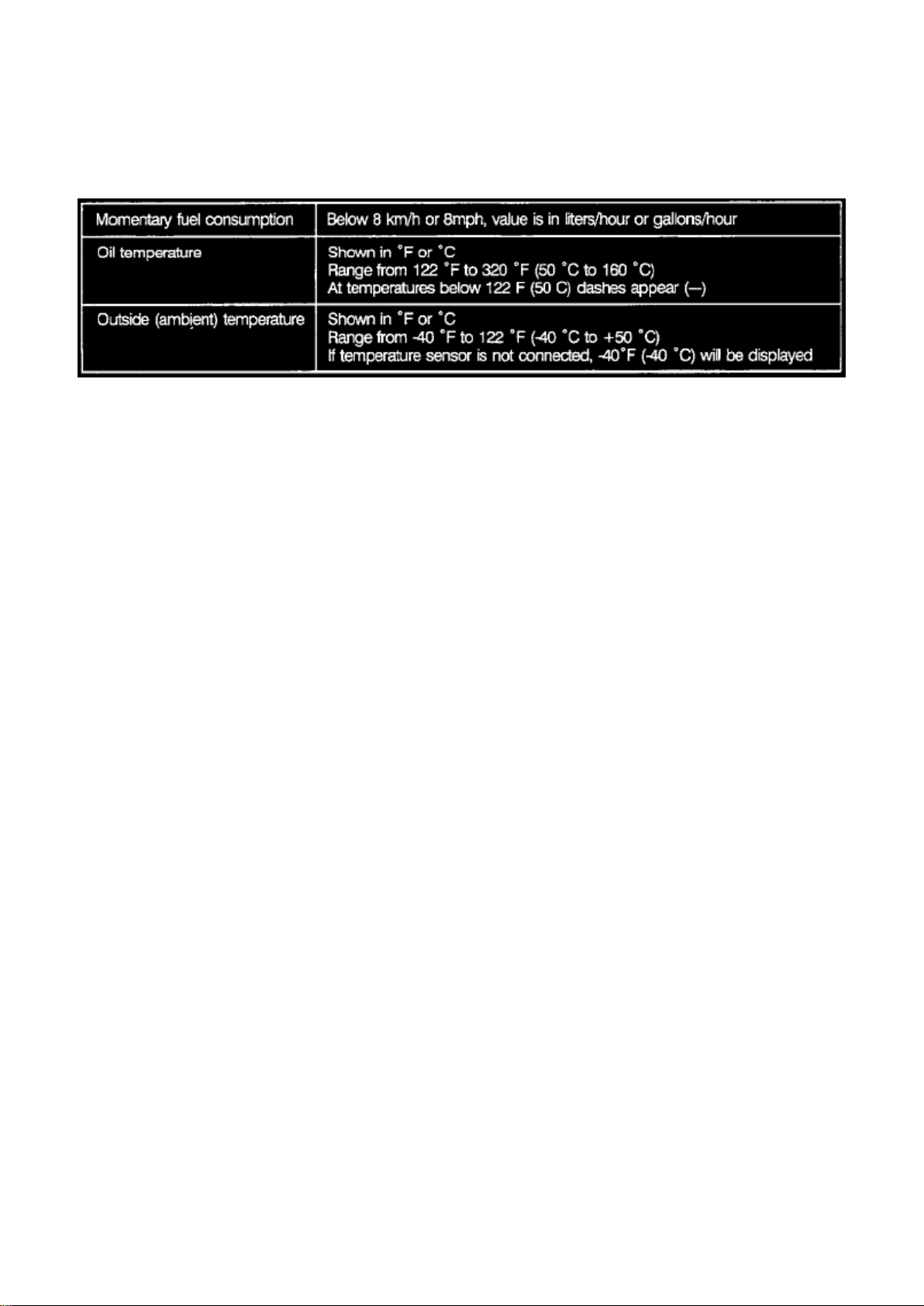
Troubleshooting - Checking Multi-function Indicator
Multi-function Indicator (MFA) Check Mode Test
If the display values for the momentary fuel consumption, oil temperature or outside air (ambient)
temperature are inaccurate, perform check mode test before attempting repairs:
- Switch ignition on
- Press multi-function indicator mode select switch E86
Page 98

- Switch ignition off, then back on and hold multi-function indicator mode select switch E86
The value for momentary fuel consumption appears in the display. Press and release mode select
switch E86 to call up oil temperature, then outside air (ambient) temperature. The selected function
appears in the display. The data in the display is aligned on the right hand side.
Page 99

Page 288
Page 100
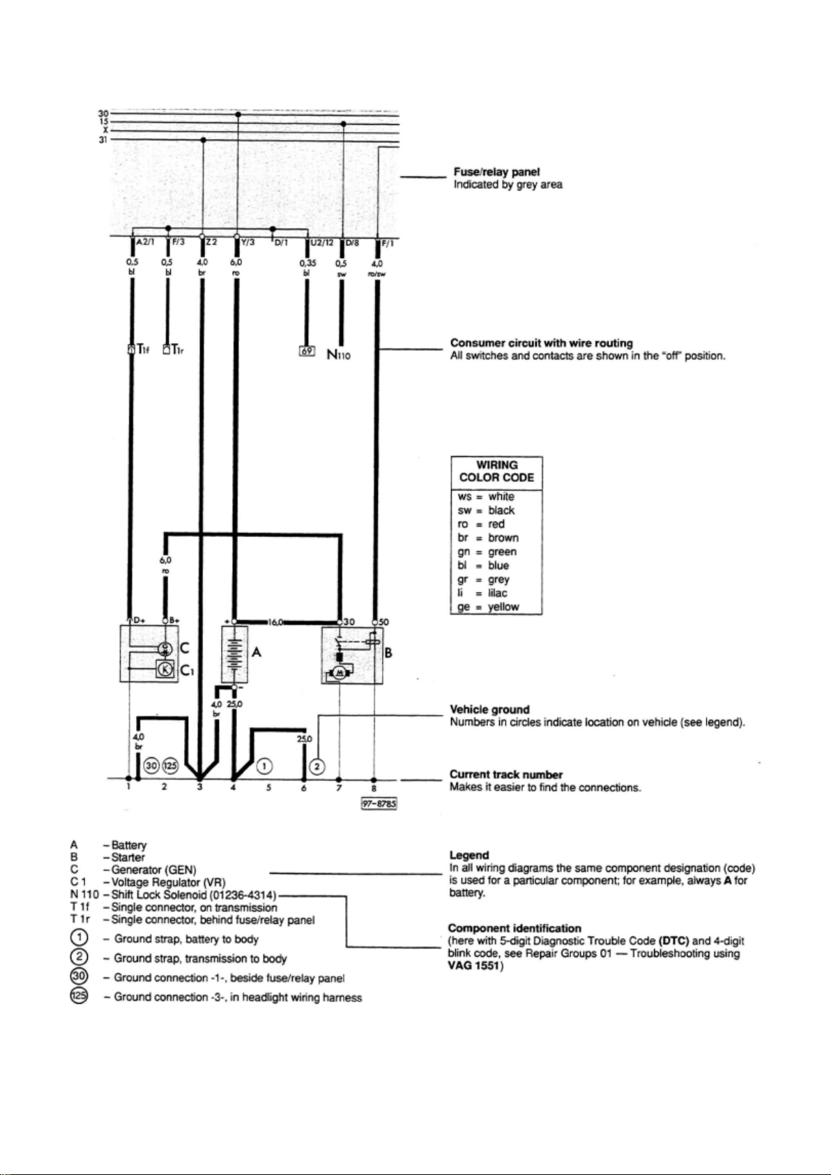
Wiring Diagram Layout
 Loading...