

Volkswagen 1.9-Liter TDI, 1.9 tdi Owner's Manual

1.9-Liter TDI Engine
with Pump Injection
(Pumpe Düse)
Design and Function
Self-Study Program
Course Number 841303

Volkswagen of America, Inc.
Service Training
Printed in U.S.A.
Printed 10/2003
Course Number 841303
©2003 Volkswagen of America, Inc.
All rights reserved. All information contained
in this manual is based on the latest
information available at the time of printing
and is subject to the copyright and other
intellectual property rights of Volkswagen of
America, Inc., its affiliated companies and its
licensors. All rights are reserved to make
changes at any time without notice. No part
of this document may be reproduced,
stored in a retrieval system, or transmitted
in any form or by any means, electronic,
mechanical, photocopying, recording or
otherwise, nor may these materials be
modified or reposted to other sites without
the prior expressed written permission of
the publisher.
All requests for permission to copy and
redistribute information should be referred
to Volkswagen of America, Inc.
Always check Technical Bulletins and the
Volkswagen Worldwide Repair Information
System for information that may supersede
any information included in this booklet.
Trademarks: All brand names and product
names used in this manual are trade names,
service marks, trademarks, or registered
trademarks; and are the property of their
respective owners.

Table of Contents
Introduction ...............................................................................1
1.9-Liter TDI Engine with Pump Injection System
Engine – Mechanics ..................................................................2
Development of the 1.9-Liter TDI Engine with Pump
Injection System, Technical Data – 1.9-Liter TDI Engine
with Pump Injection System, Trapezoidal Piston and
Connecting Rod, Toothed Belt Drive
Fuel Supply ................................................................................8
Fuel Supply System Overview, Fuel Pump,
Distributor Pipe, Fuel Cooling System
Pump Injection System ..........................................................15
Pump/Injectors, Design, Injection Cycle
Engine Management...............................................................28
1.9-Liter TDI Engine EDC 16 System Overview,
Sensors, Actuators
Glow Plug System ..................................................................53
Glow Plug System
Functional Diagram.................................................................54
EDC 16 Functional Diagram for 1.9-Liter TDI Engine
Service......................................................................................56
Self-Diagnosis, Pump/Injector Adjustment, Special Tools
Knowledge Assessment .........................................................61
The Self-Study Program provides you with information
regarding designs and functions.
The Self-Study Program is not a Repair Manual.
For maintenance and repair work, always refer to the
current technical literature.
New!
Important/Note!
i


1.9-Liter TDI Engine with
Pump Injection System
The demands on the modern diesel engine
for increased performance and fuel
economy, and reduced exhaust emissions
and noise levels are growing constantly.
Good fuel and air mixture preparation is a
key factor in meeting these requirements.
This calls for efficient injection systems that
produce high injection pressures to ensure
that the fuel is well atomized. It is also
necessary to precisely control the start of
fuel injection and the injection quantity.
The pump injection system meets
these requirements.
Introduction
In 1905, Rudolf Diesel came up with the
idea of a pump/injector, combining the
injection pump and injector in one unit
in order to dispense with high-pressure
lines and achieve high injection pressures.
At the time, however, he did not have
the technical means to put his idea
into practice.
Diesel engines with mechanically controlled
pump injection systems have been in use
in ships and trucks since the 1950s.
In association with Bosch, Volkswagen has
succeeded in developing a diesel engine
with a solenoid valve controlled pump
injection system suitable for use in
passenger cars.
The 1.9-liter TDI engine with the new pump
injection system meets the stringent
demands for improved performance and
cleaner emissions.
SSP304/032
With continuing advances like this one,
Rudolf Diesel’s vision of “smoke- and
odor-free exhaust gases” may one day
become a reality.
SSP209/027
1

Engine – Mechanics
Development of the
1.9-Liter TDI Engine with
Pump Injection System
The new 100 bhp (74 kW) 1.9-liter TDI
engine with pump injection system was
developed from the existing 109 bhp (81
kW) 1.9-liter TDI engine with a distributor
injection pump and no intermediate shaft.
The pump injection system comprises the
only significant difference between the
two engines.
This Self-Study Program concerns
the design and function of the new pump
injection system, and the modifications
to the fuel system, engine management
system, and engine mechanical
components to accommodate the system.
SSP209/005
A diesel engine with the pump injection
system has the following advantages over
an engine with a distributor injection pump:
• Low combustion noise.
• Low fuel consumption.
• Clean emissions.
• High efficiency.
These advantages are attributable to:
• The high injection pressures of up to
27,846 psi (192,000 kPa / 1,920 bar).
• Precise control of the injection cycle.
• The pre-injection phase.
2

Technical Data –
1.9-Liter TDI Engine with
Pump Injection System
Engine – Mechanics
• Engine code
BEW
• Type
Four-cylinder in-line engine with two
valves per cylinder
• Displacement
115.7 cu in (1,896 cm3)
• Bore
3.13 in (79.5 mm)
• Stroke
3.76 in (95.5 mm)
• Compression ratio
19.0 : 1
• Maximum power output
100 bhp (74 kW) @ 4000 rpm
• Maximum torque
177 lbs-ft (240 Nm) @ 1800 to 2400 rpm
• Engine management
EDC 16
lbs-ft Nm
221 300
184 250
148 200
111 150
Torque
74 100
37 50
0
1000 2000 3000 4000 5000
Speed (rpm)
hp kW
121 90
101 75
80 60
60 45
Output
40 30
20 15
0
SSP209/006
• Firing sequence
1-3-4-2
• Emission Control
Bin 10 EPA Federal Emissions Concept,
OBD II, catalytic converter, water-cooled
EGR system
3

Engine – Mechanics
Trapezoidal Piston
and Connecting Rod
To accommodate the higher combustion
pressures in the 1.9-liter TDI engine with
pump injection system than are
encountered in the base engine, the piston
hub and the connecting rod eye are
trapezoidal in shape.
4
SSP209/007

Engine – Mechanics
In comparison with the conventional
parallelogram-shaped link between the
piston and connecting rod, the trapezoidal
connecting rod eye and piston hub have a
larger contact surface area at the piston pin
owing to their shape.
Force Distribution in a Parallelogram-Shaped
Piston and Connecting Rod
Combustion Force
Contact Surface
SSP209/008
This distributes the combustion forces over
a larger area and relieves the load on the
piston pin and connecting rod.
Force Distribution in a Trapezoidal Piston
and Connecting Rod
Contact Surface
Combustion Force
SSP209/009
5

Engine – Mechanics
Toothed Belt Drive
High pump forces are required to generate
high injection pressures of up to 27,846 psi
(192,000 kPa / 1,920 bar).
These forces subject the components of
the toothed belt drive to high loads.
To relieve the load on the toothed belt,
several modifications have been made.
• A vibration absorber integrated in the
camshaft gear reduces vibration in
the toothed belt drive.
• The toothed belt is about 0.20 inch
(5 mm) wider than the toothed belt used
in the base engine. Higher forces can be
transmitted by the larger surface area.
Gap
Clearance
• A hydraulic tensioner keeps the
toothed belt evenly tensioned in
different load states.
• Some of the teeth on the crankshaft
timing belt gear have a larger gap
clearance to reduce toothed belt wear.
SSP209/089
To relieve the load on the toothed belt
during the injection cycle, the crankshaft
timing belt gear has two pairs of teeth with
a larger gap clearance than the other teeth.
SSP209/88
6
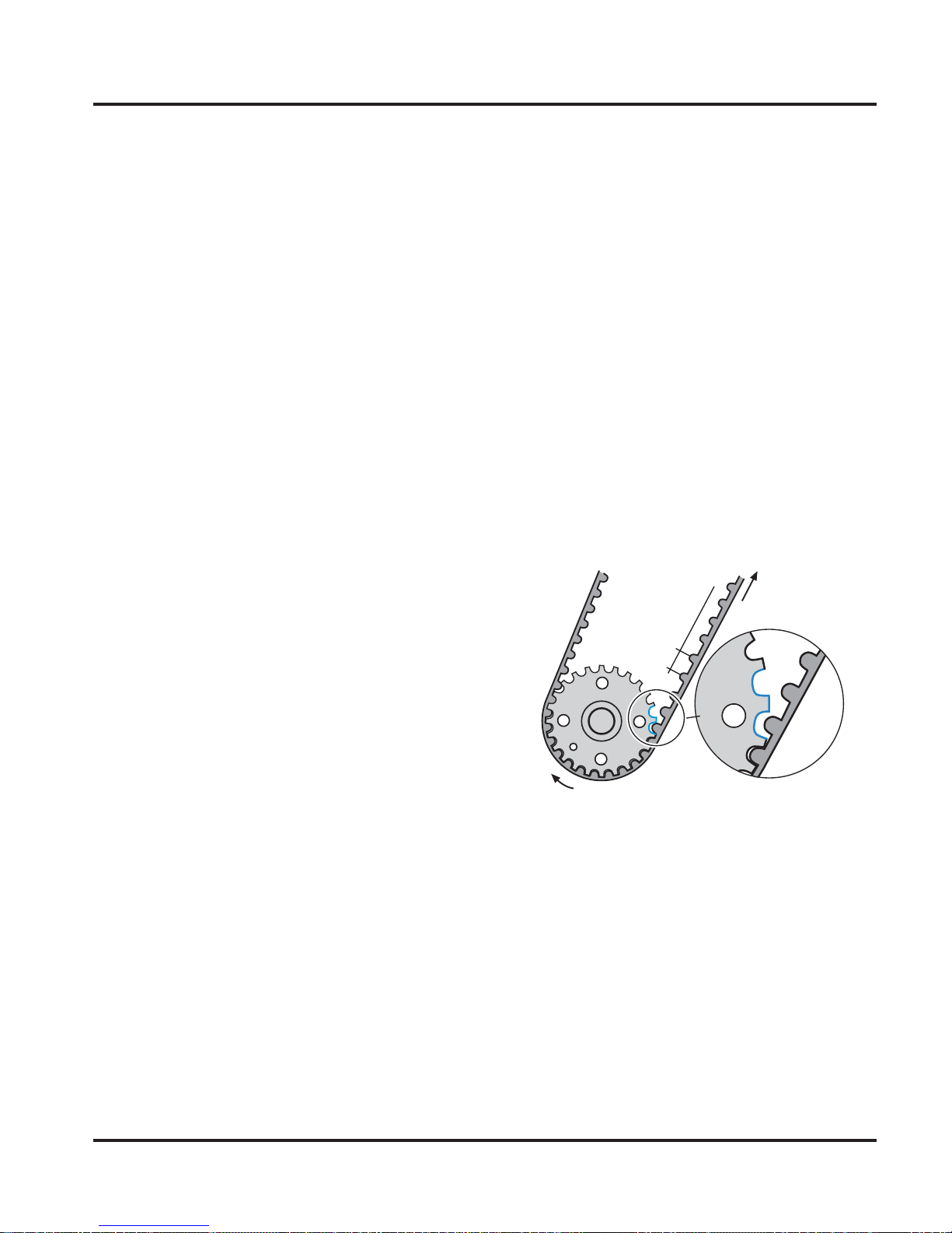
Function
During the injection cycle, the high
pumping forces exert a heavy load on the
toothed belt.
The camshaft timing belt gear is slowed
down by the pumping forces. At the same
time, the combustion process speeds up
the crankshaft timing belt gear. The toothed
belt is stretched and the pitch is temporarily
increased as a result.
Because of the engine firing order, this
stretching process occurs at regular
intervals and the same teeth on the timing
belt gear are in mesh with the toothed belt
every time.
Engine – Mechanics
Deceleration Force
Non-uniform tooth gap clearance
On the 1.9-liter TDI engine with pump
injection system, the crankshaft timing belt
gear teeth have a larger gap clearance at
these points to compensate for the change
in belt tooth pitch and thus reduce toothed
belt wear.
Acceleration Force
Pitch
SSP209/091
7

Fuel Supply
Fuel Supply System Overview
A mechanical fuel pump sucks the fuel out
of the fuel tank through the fuel filter and
pumps it along the supply line in the
cylinder head to the pump/injectors.
Fuel Cooler – Cools the returning fuel
to prevent excessively hot fuel from
being routed back to the fuel tank.
The fuel that is not required for injection is
returned to the fuel tank via the return line
in the cylinder head, a fuel temperature
sensor, and a fuel cooler.
Fuel Temperature Sensor G81 –
Determines the temperature of the
fuel in the fuel return line and sends a
corresponding signal to the Diesel Direct
Fuel Injection Engine Control Module J248.
Fuel Tank
8
Fuel Filter – Protects the injection
system against contamination and
wear caused by particles and water.
Non-Return Valve – Prevents fuel
from the fuel pump flowing back into
the fuel tank while the engine is not
running. It has an opening pressure
of 2.9 psi (20 kPa / 0.2 bar).

Pressure Limiting V alve Bypass –
If there is air in the fuel system,
for example when the fuel tank
is empty, the pressure limiting
valve remains closed. The air is
expelled from the system by the
fuel flowing into the tank.
Fuel Supply
Cylinder Head
Fuel Return Line Pressure
Limiting Valve – Keeps the
pressure in the fuel return line
at 14.5 psi (100 kPa / 1 bar).
This maintains a force
equilibrium at the pump/
injector solenoid valve needle.
Restrictor – Located between the
fuel supply line and the fuel return
line. Vapor bubbles in the fuel supply
line are separated through the
restrictor into the fuel return line.
Fuel Supply Line Pressure Limiting Valve –
Regulates the fuel pressure in the fuel supply line.
The valve opens when the fuel pressure exceeds
109 psi (750 kPa / 7.5 bar). Fuel is routed back to
the suction side of the fuel pump.
Strainer – Collects vapor bubbles in the
fuel supply line. These vapor bubbles are
then separated through the restrictor
into the return line.
Fuel Pump Rotor – Pumps the fuel from
the fuel tank through the fuel filter and
the fuel supply line in the cylinder head
to the pump/injectors.
SSP209/018
9

Fuel Supply
Fuel Pump
The fuel pump is located directly behind
the vacuum pump at the cylinder head.
It moves the fuel from the fuel tank to the
pump/injectors.
Both pumps are driven jointly by the
camshaft. They are collectively known as
a tandem pump.
There is a fitting on the fuel
pump for connecting pressure
gauge VAS 5187 to check the
fuel pressure in the supply line.
Please refer to the Repair Manual
for instructions.
Vacuum Pump
Fuel Pump
Fuel Return Line
Fuel Supply Line
Pressure Gauge
Connection Fitting
SSP209/049
10

Fuel Supply
The fuel pump is a blocking vane-cell pump.
The blocking vanes are pressed against the
pump rotor by spring pressure. This design
enables the fuel pump to deliver fuel even
at low engine speeds.
Fuel Supply Line
Pressure Limiting Valve
Connection for
Fuel Supply Line
The fuel ducting system within the pump
is designed so that the rotor always
remains wetted with fuel, even if the tank
has been run dry. This makes automatic
priming possible.
Blocking Vanes
Restrictor
From Fuel
Return Line in
Cylinder Head
Fuel Return
Line Pressure
Limiting Valve
Connection for
Fuel Return Line
Rotor
Strainer
To Fuel Supply Line
in Cylinder Head
SSP209/050
11

Fuel Supply
Chamber 4 Chamber 3
Chamber 1
Chamber 2
Function
The fuel pump operates by taking fuel in as
the pump chamber volume increases and
pushing the fuel out under pressure as the
chamber volume is reduced.
The fuel is drawn into two chambers and
pumped out from two chambers. The
intake and delivery chambers are separated
from one another by the spring-loaded
blocking vanes and the pump rotor lobes.
Fuel drawn into chamber 1 is pushed out at
chamber 2. Fuel drawn into chamber 3 is
pushed out at chamber 4.
The rotation of the rotor increases the
volume of chamber 1 while the volume of
SSP209/052Rotor
chamber 4 is simultaneously reduced.
Fuel is pushed out of chamber 4 to the
fuel supply line in the cylinder head.
Chamber 1
Chamber 4
Chamber 3
The rotation of the rotor increases the
volume in chamber 3 as it reduces the
volume in chamber 2. Fuel drawn in at
chamber 1 is forced out of chamber 2 to
the fuel supply line in the cylinder head.
Chamber 2
Rotor
SSP209/051
12

Distributor Pipe
A distributor pipe is integrated in the fuel
supply line in the cylinder head. It distributes
the fuel evenly to the pump/injectors at a
uniform temperature.
Annular Gap
Fuel Supply
SSP209/040
Cylinder 4Cylinder 3Cylinder 2Cylinder 1
Cylinder Head
In the supply line, the fuel moves through
the center of the distributor pipe toward
cylinder 1 at the far end.
The fuel also moves through the cross
holes in the distributor pipe and enters the
annular gap between the distributor pipe
and the cylinder head wall.
This fuel mixes with the hot unused fuel
that has been forced back into the supply
line by the pump/injectors.
This results in a uniform temperature
of the fuel in the supply line running to
all cylinders.
All pump/injectors are supplied with
the same fuel mass, and the engine
runs smoothly.
Cross Holes
Mixing Fuel in
Annular Gap
Distributor Pipe
SSP209/039
Fuel to Pump/Injector
Fuel from
Pump/Injector
Cross Holes
SSP209/29
13

Fuel Supply
Fuel Cooling System
The high pressure generated by the pump/
injectors heats up the unused fuel so much
that it must be cooled before it gets back to
the fuel tank.
A fuel cooler is located on the fuel filter.
It cools the returning fuel and thus prevents
excessively hot fuel from entering the fuel
tank and possibly damaging the Sender for
Fuel Gauge G.
Fuel Cooling Circuit
The heated fuel returning from the pump/
injectors flows through the fuel cooler and
its heat transfers to the coolant in the fuel
cooling circuit that also flows through the
fuel cooler.
The auxiliary water cooler reduces the
temperature of the coolant in the fuel
cooling circuit by dissipating the heat in
the coolant to the ambient air.
Pump for Fuel Cooler V166 is an electric
recirculation pump. It circulates the coolant
in the fuel cooling circuit through the
auxiliary water cooler and the fuel cooler. It
is switched on by the Diesel Direct Fuel
Injection Engine Control Module J248 via
the Relay for Pump, Fuel Cooling J445 at
a fuel temperature of 158°F (70°C).
The fuel cooling circuit is largely separate
from the engine cooling circuit. This is
necessary because the temperature of the
coolant in the engine cooling circuit is too
high to cool down the fuel when the engine
is at operating temperature.
The fuel cooling circuit is connected to the
engine cooling circuit near the expansion
tank. This enables replenishment of the
coolant for fuel cooling at the coolant
expansion tank. It also allows
compensation for changes in volume due
to temperature fluctuation.
The fuel cooling circuit is connected so that
the hotter engine cooling circuit does not
have a detrimental effect on its ability to
cool the fuel.
Fuel
Temperature
Sensor G81
Fuel Pump
Auxiliary
Water
Cooler
14
Fuel Cooler
Pump for
Fuel Cooler
V166
Fuel Tank
Engine
Cooling
Circuit
Coolant
Expansion
Tank
SSP209/048

Pump/Injectors
Pump Injection System
A pump/injector is, as the name implies, a
pressure-generating pump combined with a
solenoid valve control unit (V alves for Pump/
Injectors, Cylinders 1 through 4, N240,
N241, N242, and N243) and an injector.
Each cylinder of the engine has its own
pump/injector.
This means that there is no longer any
need for a high-pressure line or a distributor
injection pump.
PressureGenerating
Pump
Just like a conventional system with a
distributor injection pump and separate
injectors, the new pump injection
system must:
• Generate the high injection
pressures required.
• Inject fuel into the cylinders in the correct
quantity and at the correct point in time.
Injector
Solenoid Valve Control Unit
SSP209/012
15

Pump Injection System
SSP209/086
The pump/injectors are installed directly in
the cylinder head.
Clamping
Block
They are attached to the cylinder head by
individual clamping blocks.
It is important to ensure that
the pump/injectors are positioned
correctly when they are installed.
Refer to the Repair Manual
for instructions.
If the pump/injectors are not installed
perpendicular to the cylinder head, the
fasteners could loosen. The pump/injectors
or the cylinder head could be damaged as
a result.
16
SSP209/087

Design
Roller-Type
Rocker Arm
Pump Injection System
Ball Pin
Injection Cam
High-Pressure
Chamber
O-Ring
Retraction
Piston
O-Ring
Pump Piston
Piston Spring
Solenoid
Valve Needle
Pump/Injector
Solenoid V alve
Fuel Return Line
Fuel Supply Line
O-Ring
HeatInsulating
Seal
Cylinder Head
Injector Spring
Injector Needle
Damping Element
Injector Needle
SSP209/023
17
 Loading...