

Volkswagen 1995 Volkswagen Golf III GL, 1995 Golf III GL Service Manual
1995-98 ENGINES
Volkswagen - 2.0L 4-Cylinder
ENGINE IDENTIFICATION
On all models except Beetle, engine identification number is stamped on a machined pad on left side of
engine block, above crankcase breather. See
Fig. 1
. On Beetle, engine identification number is located on
left side of cylinder block, near transmission.
ENGINE CODES
NOTE: For engine repair procedures not covered in this article, see ENGINE
OVERHAUL PROCEDURES - GENERAL INFORMATION article in the
GENERAL INFORMATION section.
Application Code
2.0L Except Beetle ABA
2.0L Beetle AEG
1995 Volkswagen Golf III GL
2.0L 4-CYL
1 января 2005 г. 1:18:58 Page 1 © 2004 Mitchell Repair Information Company, LLC.

Fig. 1: Locating Engine Identification Number (Except Beetle)
Courtesy of VOLKSWAGEN UNITED STATES, INC.
ADJUSTMENTS
VALVE CLEARANCE
Engine is equipped with hydraulic lifters. Adjustment is not necessary. Valve noise during startup is
considered normal.
REMOVAL & INSTALLATION
CAUTION: Radio/cassette or radio/CD player is equipped with an anti-theft protection
circuit. Whenever battery is disconnected, radio will go into anti-theft mode.
When battery is reconnected, radio will display CODE, and will be
inoperative until proper code number is entered. Obtain security code before
disconnecting battery.
1995 Volkswagen Golf III GL
2.0L 4-CYL
1 января 2005 г. 1:18:59 Page 2 © 2004 Mitchell Repair Information Company, LLC.

FUEL PRESSURE RELEASE
Remove fuel pump relay (located in fuse/relay panel). Crank engine for 5 seconds. Turn ignition switch off.
Reinstall fuel pump relay.
RADIATOR
Removal & Installation (Jetta)
1. Disconnect and remove battery. Drain engine coolant by disconnecting coolant hose from thermostat
housing. Disconnect radiator hoses. Disconnect fan harness connectors. Remove headlights. Remove
radiator mounting bolts.
2. On vehicles equipped with A/C, remove air cleaner. Remove A/C line retaining clamps. DO NOT
disconnect hoses. Separate condenser from radiator and move radiator forward.
3. On all vehicles, remove radiator. To install, reverse removal procedure. Fill cooling system. Adjust
headlights.
Removal & Installation (Beetle)
1. Remove center undercar tray. Drain coolant from radiator. Remove front inner fenders. Remove
fender bolts from inside of fender. See
Fig. 2
. Remove lower fender bolts. Remove screws from rear
of fender. Remove 3 screws from under front of bumper cover. Remove 16 screws under hood
attaching fenders and bumper cover to vehicle. With a helper, remove front fenders and bumper cover
as an assembly.
2. Disconnect hood latch cable. Remove upper bumper bolt on each side and install Special Tools
(3411). See
Fig. 3
. Remove upper panel bolts and remaining bumper bolts. Slide entire lock carrier
assembly out on special tools.
3. Disconnect radiator hoses. Disconnect radiator mounted switch harness connectors. Remove radiator
mounting bolts. See
Fig. 4
. On vehicles equipped with A/C, remove A/C line retaining clamps. DO
NOT disconnect hoses. Fasten condenser to lock carrier before removing radiator. On all vehicles,
remove radiator. To install, reverse removal procedure. Fill cooling system. Adjust headlights.
NOTE: For reassembly reference, label all electrical connectors,vacuum hoses and
fuel lines before removal. Place mating marks on other major assemblies
before removal.
NOTE: Obtain radio anti-theft code before disconnecting battery.
1995 Volkswagen Golf III GL
2.0L 4-CYL
1 января 2005 г. 1:18:59 Page 3 © 2004 Mitchell Repair Information Company, LLC.

1995 Volkswagen Golf III GL
2.0L 4-CYL
1 января 2005 г. 1:18:59 Page 4 © 2004 Mitchell Repair Information Company, LLC.

Fig. 2: Removing Front Fenders & Bumper Cover
Courtesy of VOLKSWAGEN UNITED STATES, INC.
1995 Volkswagen Golf III GL
2.0L 4-CYL
1 января 2005 г. 1:18:59 Page 5 © 2004 Mitchell Repair Information Company, LLC.
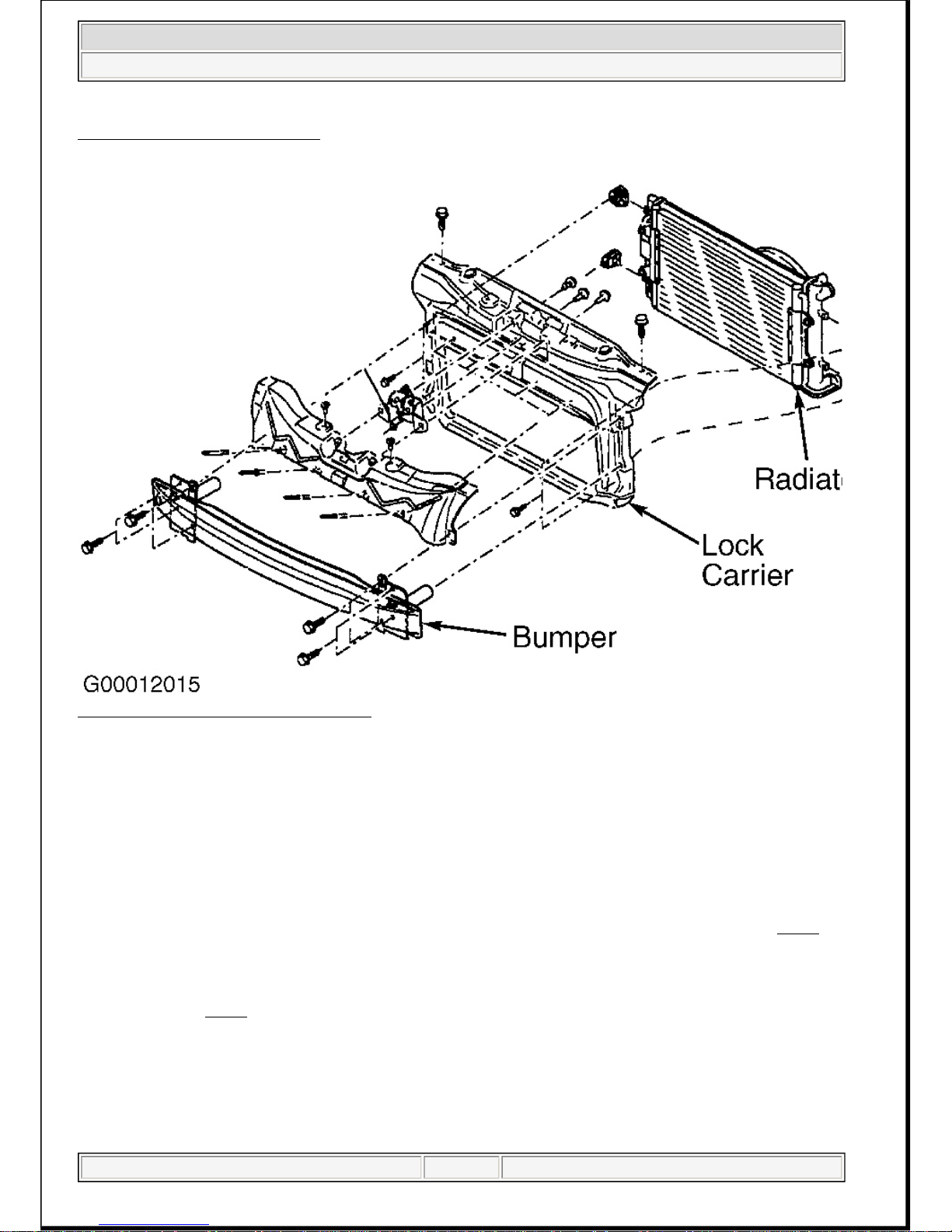
Fig. 3: Sliding Out Lock Carrier
Courtesy of VOLKSWAGEN UNITED STATES, INC.
Fig. 4: Exploded View Of Lock Carrier
Courtesy of VOLKSWAGEN UNITED STATES, INC.
ENGINE
Removal (Except Beetle)
1. Disconnect and remove battery. Drain engine coolant by disconnecting coolant hose from thermostat
housing. Disconnect radiator hoses. Remove front bumper/grille assembly (lock carrier). See
Fig. 5
.
2. On vehicles equipped with A/C, it is not necessary to discharge A/C system. Remove receiver-dryer
mounting bolts. DO NOT disconnect hoses from receiver-dryer. Remove accessory drive belt.
Remove radiator with fan and condenser attached. Set radiator/condenser assembly in front of engine
mount. See
Fig. 6
. Remove A/C compressor with hoses attached and set aside with
radiator/condenser assembly. DO NOT stress refrigerant hoses.
3. On all vehicles, remove intake air duct. Disconnect all electrical connectors, cables and hoses that
interfere with engine removal. Disconnect power steering pump with bracket and set aside. DO NOT
disconnect power steering hoses. Remove axle shafts from transaxle. See AXLE SHAFTS - FRONT
article in DRIVE AXLES. Leave fuel lines connected and remove cold start injector and warm-up
re
g
ulator.
NOTE: Engine is removed from vehicle with transaxle attached. Obtain radio anti-
theft code before disconnecting battery.
1995 Volkswagen Golf III GL
2.0L 4-CYL
1 января 2005 г. 1:18:59 Page 6 © 2004 Mitchell Repair Information Company, LLC.

4. Remove fuel injectors. Remove rear engine mount. Remove complete transaxle mount. Disconnect
exhaust pipe from exhaust manifold. On M/T models, disconnect clutch cable. Attach Engine Sling
(2024A) to engine. On A/T models, remove crankshaft pulley and water pump pulley. Install engine
sling on engine lift hooks. Carefully raise engine and transaxle out of vehicle. Separate transaxle from
engine.
1995 Volkswagen Golf III GL
2.0L 4-CYL
1 января 2005 г. 1:18:59 Page 7 © 2004 Mitchell Repair Information Company, LLC.

Fig. 5: Placing Lock Carrier In Service Position
Courtesy of VOLKSWAGEN UNITED STATES, INC.
1995 Volkswagen Golf III GL
2.0L 4-CYL
1 января 2005 г. 1:18:59 Page 8 © 2004 Mitchell Repair Information Company, LLC.

Fig. 6: Removing A/C Condenser With Hoses Attached
Courtesy of VOLKSWAGEN UNITED STATES, INC.
Removal (Beetle)
1. Disconnect and remove battery. Relieve fuel pressure. See
FUEL PRESSURE RELEASE
. Remove
engine cover. Remove power steering reservoir from battery tray with hoses attached and secure
aside. Disconnect fuel supply and return hoses from fuel rail.
2. Remove air cleaner. Disconnect shift linkage from transmission. On M/T models, remove slave
cylinder. On all models, remove engine undercover. Drain engine coolant from radiator. Drain engine
coolant from engine by disconnecting coolant hose from oil cooler.
3. Remove accessory drive belt. Remove cooling fan on right side of vehicle (if equipped). Remove
power steering hose brackets. Remove power steering pump with hoses attached and set aside.
4. On vehicles equipped with A/C, it is not necessary to discharge A/C system. Remove refrigerant hose
brackets. Remove A/C compressor with hoses attached. Secure A/C compressor aside to prevent
stressing hoses.
5. Disconnect any hoses interfering with engine/transmission removal. Remove secondary air injection
pump. Disconnect any electrical connectors necessary for engine/transmission removal. Remove
torque rod from transmission.
6. Remove axle shafts from transmission. See AXLE SHAFTS - FRONT article in DRIVE AXLES.
Remove exhaust pipe from exhaust manifold. Remove coolant hose bracket under engine block.
1995 Volkswagen Golf III GL
2.0L 4-CYL
1 января 2005 г. 1:18:59 Page 9 © 2004 Mitchell Repair Information Company, LLC.

Support engine/transmission assembly with suitable jack.
7. Remove engine mount-to-engine bolts. Remove transmission mount-to-transmission bolts. Carefully
lower engine/transmission assembly. Ensure power steering hoses clear transmission. Separate
transmission from engine.
Installation (Except Beetle)
1. To install, reverse removal procedure. Engine alignment adjustment is necessary whenever engine is
removed or mounts are loosened. To adjust, loosen through-bolt on engine mount. Loosen transaxle
mount bolts. Loosen front engine mount and bracket.
2. Lightly rock engine and transaxle to allow position to shift as necessary. Evenly tighten mount bolts
in reverse order of loosening. Fill fluids to proper level. Adjust clutch pedal (if equipped). Tighten all
bolts and nuts to specification. See
TORQUE SPECIFICATIONS
.
Installation (Beetle)
1. To install, reverse removal procedure. Ensure engine/transmission assembly are aligned.
Engine/transmission are aligned when there is .39" (10.0 mm) distance between top engine mount and
engine mount bracket. See
Fig. 7
.
2. On A/T models, use NEW lock washer on shift cable. On all models, adjust all cables as necessary.
Fill fluids to proper level. Tighten all fasteners to specification. See
TORQUE SPECIFICATIONS
.
1995 Volkswagen Golf III GL
2.0L 4-CYL
1 января 2005 г. 1:18:59 Page 10 © 2004 Mitchell Repair Information Company, LLC.

Fig. 7: Aligning Engine/Transmission Assembly (Beetle)
Courtesy of VOLKSWAGEN UNITED STATES, INC.
ENGINE MOUNT RUBBER BUSHING
Removal & Installation (Cabrio, Golf, GTI & Jetta)
1. Support engine from above, using engine support bracket, or the like. Connect engine sling in hook
eye on cylinder head (left side) and tighten to lift engine slightly. Remove engine mount.
2. Pry washers off spacer sleeves with pliers. Remove spacer sleeves and pull off bonded rubber
bushings, see
Fig. 8
. Install new bonded rubber bushings and insert spacer sleeves as far as possible.
3. Install washers (1) over Peening Punch (3302) and onto bonded rubber bushing (2), see
Fig. 9
. Install
pressure sleeve peening punch and press on.
4. Crimp washers on spacer sleeves using press. Use Arbor (VW432) as support. If necessary, remove
b
urrs caused by crimping.
NOTE: To see exploded views of component locations, see Fig. 10 -Fig. 13 .
1995 Volkswagen Golf III GL
2.0L 4-CYL
1 января 2005 г. 1:18:59 Page 11 © 2004 Mitchell Repair Information Company, LLC.

Fig. 8: Removing Engine Mount Rubber Bushings
Courtes
y
of AUDI OF AMERICA, INC.
1995 Volkswagen Golf III GL
2.0L 4-CYL
1 января 2005 г. 1:18:59 Page 12 © 2004 Mitchell Repair Information Company, LLC.

Fig. 9: Installing Engine Mount Rubber Bushing Washers
Courtesy of AUDI OF AMERICA, INC.
1995 Volkswagen Golf III GL
2.0L 4-CYL
1 января 2005 г. 1:18:59 Page 13 © 2004 Mitchell Repair Information Company, LLC.

Fig. 10: Front Engine/Transmission Mount
Courtesy of AUDI OF AMERICA, INC.
1995 Volkswagen Golf III GL
2.0L 4-CYL
1 января 2005 г. 1:18:59 Page 14 © 2004 Mitchell Repair Information Company, LLC.

Fig. 11: Right Rear Engine/Transmission Mount
Courtesy of AUDI OF AMERICA, INC.
1995 Volkswagen Golf III GL
2.0L 4-CYL
1 января 2005 г. 1:18:59 Page 15 © 2004 Mitchell Repair Information Company, LLC.

Fig. 12: Right Engine/Transmission Mount (Cabrio Only)
Courtesy of AUDI OF AMERICA, INC.
1995 Volkswagen Golf III GL
2.0L 4-CYL
1 января 2005 г. 1:19:00 Page 16 © 2004 Mitchell Repair Information Company, LLC.

Fig. 13: Left Rear Engine/Transmission Mount
Courtesy of AUDI OF AMERICA, INC.
INTAKE MANIFOLD (UPPER & LOWER)
Removal and installation procedures are not available from manufacturer. See
TORQUE
SPECIFICATIONS
.
CYLINDER HEAD
Removal (Except Beetle)
1. Allow engine to cool. Label and disconnect electrical connectors and vacuum hoses. Disconnect
throttle, cruise and kickdown cables. Leave fuel lines connected and remove cold start injector and
warm-up regulator.
2. Remove fuel injectors. Remove crankcase breather pressure regulating valve. Remove upper part of
intake manifold. Remove cylinder head cover (rocker arm cover). Remove timing belt. See TIMING
BELT. Disconnect exhaust pipe from exhaust manifold.
3. Ensure pistons are NOT at TDC. Remove timing belt inner cover. Remove cylinder head bolts in
reverse sequence of installation. See
Fig. 14
. Replace cylinder head bolts after loosening or
removing.
CAUTION: DO NOT turn crankshaft or camshaft with timing belt removed. Valve damage
may result.
NOTE: Cracks .02" (.5 mm) wide or less (.01" (.3 mm) or less on Beetle) between
1995 Volkswagen Golf III GL
2.0L 4-CYL
1 января 2005 г. 1:19:00 Page 17 © 2004 Mitchell Repair Information Company, LLC.

Removal (Beetle)
1. Allow engine to cool. Disconnect negative battery cable. Remove engine cover. Release fuel pressure.
See
FUEL PRESSURE RELEASE
. Drain engine coolant from radiator. Drain engine coolant from
cylinder block by disconnecting coolant hose from oil cooler.
2. Disconnect fuel hoses from fuel rail. Remove air cleaner. Disconnect throttle cable from Throttle
Valve Control Module (TVCM). Disconnect hoses and electrical connector from TVCM. Remove
upper intake manifold-to-lower intake manifold front bolts.
3. Disconnect hoses from intake manifold, secondary air injection valve and fuel pressure regulator (as
necessary). Remove warm air deflector bolts. Disconnect hoses from fuel pressure regulator.
Disconnect electrical connectors from fuel injectors and camshaft position sensor.
4. Remove hoses from secondary air injection pump. Disconnect spark plug wires from spark plugs.
Remove accessory drive belt and tensioner. Remove upper timing belt cover. Ensure pistons are NOT
at TDC. Remove timing belt tensioner. Remove timing belt from camshaft pulley. See
TIMING
BELT
.
5. Disconnect exhaust pipe from exhaust manifold. Remove valve cover. Loosen cylinder head bolts in
reverse order of tightening sequence. See
Fig. 14
. Remove cylinder head.
Inspection (All Models)
Thoroughly clean all gasket mating surfaces. Check cylinder head for warpage. Maximum warpage
is .004" (.100 mm). Check minimum cylinder head height and replace cylinder head (if necessary). See
CYLINDER HEAD
table under ENGINE SPECIFICATIONS.
Installation (Except Beetle)
1. Install Guide Pins (3070) into bolt holes No. 8 and 10. Install NEW head gasket on cylinder block
with part number facing up. DO NOT use any type of sealant. Ensure pistons are NOT at TDC.
2. Carefully position cylinder head on cylinder. Install 8 remaining head bolts finger tight. Remove
guide pins with extractor (3070). Install remaining head bolts finger tight.
3. Tighten cylinder head bolts in sequence to specification. See
Fig. 14
. See
TORQUE
SPECIFICATIONS
. To complete installation, reverse removal procedure. Tighten all fasteners to
specification. See
TORQUE SPECIFICATIONS
. Fill radiator with NEW coolant. Fill all fluids to
proper level.
Installation (Beetle)
valve seats or between valve seat and spark plug threads are considered
acceptable by manufacturer.
NOTE: DO NOT reuse antifreeze after replacing cylinder block, cylinder head, head
gasket, radiator and/or heater core.
CAUTION: If camshaft or cam followers are changed, and cam followers are charged
with oil, allow 30 minutes for followers to bleed down before starting engine.
Pistons may strike valves, resulting in bent valves.
CAUTION: Ensure cylinder head bolt holes are clean and free of oil or coolant.
Hydrostatic lock may occur when tightening cylinder head bolts
1995 Volkswagen Golf III GL
2.0L 4-CYL
1 января 2005 г. 1:19:00 Page 18 © 2004 Mitchell Repair Information Company, LLC.
 Loading...