

Page 1

VT-Series
Ice Maker
Model
VT40, VT60, VT80, VT100
Revision Date: 1/04/12
Page 2

NOTICE
This manual is the property of the owner of this particular Vogt
Tube-Ice® machine.
Model #____________________ Serial #____________________.
It is to be left on the premises with this machine at all times. After
start-up, it should be stored in a safe place where it can be readily
available when needed for future reference in maintaining
troubleshooting or servicing.
Failure to comply with this notice will result in unnecessary
inconvenience and possible additional expenses.
This manual is intended as an informational tool for the installation,
operation, maintenance, troubleshooting, and servicing of this
equipment. If an existing situation calls for additional information
not found herein, we suggest that you contact your distributor first.
If further assistance or information is needed, please feel free to
contact the factory at 502-635-3000 or FAX at 502-635-3024.
IMPORTANT: The Warranty Registration/Start-Up Report found in
the front of this manual is to be completed and returned to the factory
promptly after the official start-up.
Please return to: VOGT ICE
, LLC
1000 W. Ormsby Ave.
Louisville, KY 40210
Page 3

FOREWORD
Vogt Ice®, LLC, strives to provide a quality product that is time-tested and will
provide years of dependable service to its customers.
Skilled craftsmen have carefully assembled your Vogt
material components and parts available from the leading vendors and producers of
the highest quality refrigeration equipment in our industry. You have invested in
quality equipment, and we pledge to support your needs and requirements after the
sale.
This manual is provided to aid the service technician and users in the installation,
operation, and maintenance of your equipment. Before attempting to install and
start the machine, the installer should read and understand each section of this
manual.
If, at any time, you encounter conditions that we have not addressed in this manual,
we welcome you to write or call Vogt
immediate attention and reply.
®
Ice, LLC and we will give your questions our
®
VT Series ice maker using
Vogt Ice®, LLC
1000 W. Ormsby Avenue
Suite 19
Louisville, KY 40210
(502) 635-3000
(502) 634-3024 Fax
Page 4

TABLE OF CONTENTS
General Information - Section 1
History of Company............................................................................................. 1-1
Receipt of Your Ice Machine ............................................................................... 1-2
Installation Information - Section 2
Important Safety Notice....................................................................................... 2-1
Machine Dimension............................................................................................. 2-2
Machine Weights & Refrigerant Line Sizes.......................................................... 2-2
Ice Chute Cutout ................................................................................................. 2-3
Water Connections.............................................................................................. 2-4
Water Flow Rates / Water Tank Capacity............................................................ 2-4
Electrical Connections......................................................................................... 2-5
Air Cooled Condenser Electrical Connections .................................................... 2-6
Lowside Electrical Connections..............................................................................2-6
Air Cooled Condenser Installation ....................................................................... 2-7
Air Cooled Condenser Wiring ............................................................................. 2-9
Storing Ice – Bin Thermostat Mounting ............................................................. 2-12
Model Specifications and Wiring Diagrams - Section 3
Model Specifications ........................................................................................... 3-1
Model Number Structure .................................................................................... 3-2
Initial Startup - Section 4
Startup Procedure ............................................................................................... 4-1
Circuit Breakers & Lowside Control Panel Front.................................................. 4-2
Service Valve Locations ...................................................................................... 4-3
Adding Refrigerant .............................................................................................. 4-4
Suction Line Access Port..................................................................................... 4-4
Removing Refrigerant ......................................................................................... 4-5
Electrical Controls - Section 5
Explanation of Controls........................................................................................ 5-1
Startup & Standby Mode ..................................................................................... 5-1
Freeze Mode ...................................................................................................... 5-1
PLC & Freezer Timer .......................................................................................... 5-1
Harvest Mode ...................................................................................................... 5-2
Harvest Hold Pressure Switch
Clean Mode......................................................................................................... 5-3
Fault Mode & Faults Designations ....................................................................... 5-3
PLC Input / Output Table..................................................................................... 5-4
Electrical Schematic
Electrical Schematic
Lowside Electrical Schematic .............................................................................. 5-7
Lowside Control Panel Layout ............................................................................ 5-8
Condensing Unit Electrical Schematic
Condensing Unit Control Panel Layout
Condensing Unit Electrical Schematic
Condensing Unit Control Panel Layout
(Standard)
(CE)
(Increasing Harvest)
............................................................................ 5-5
..................................................................................... 5-6
(Standard)
(Standard)
(CE)
....................................................... 5-11
(CE)
............................................... 5-2
................................................. 5-9
.............................................. 5-10
...................................................... 5-12
Page 5

Maintenance - Section 6
Preventive Maintenance ..................................................................................... 6-1
Preventive Maintenance Program ....................................................................... 6-2
Air Cooled Condenser Cleaning .......................................................................... 6-3
Compressor Oil ................................................................................................... 6-3
Chopper Gear Reducer Oil.................................................................................. 6-4
Water Distributor ................................................................................................. 6-4
Troubleshooting - Section 7
Machine Fault Light ............................................................................................ 7-1
Control Power Light ............................................................................................ 7-1
PLC ..................................................................................................................... 7-2
Damaged Bin Control Sensor .............................................................................. 7-2
Machine Inoperative ............................................................................................ 7-3
Machine “Freeze-Up”........................................................................................... 7-4
Additional Troubleshooting ................................................................................. 7-5
Service Operations - Section 8
Principle Of Operation ........................................................................................ 8-1
Pressure Switches .............................................................................................. 8-2
CoreSense
Bin Control
PLC
Compressor......................................................................................................... 8-6
TXV & Solenoid Valve ......................................................................................... 8-7
Adjusting TXV...................................................................................................... 8-8
Inlet Pressure Regulator...................................................................................... 8-8
Water Tank Parts ............................................................................................... 8-9
Chopper Assembly ........................................................................................... 8-10
Evaporator Housing Covers .............................................................................. 8-11
Freeze Cycle Piping Schematic
Harvest Cycle Piping Schematic
Freeze Cycle Piping Schematic
Harvest Cycle Piping Schematic
Freeze Cycle Piping Schematic
Harvest Cycle Piping Schematic
Replacement Parts List .................................................................................... 8-18
(Programmable Logic Controller)
(Copeland Compressor Protection
(Electronic Temperature Control)
...................................................................... 8-5
(No Hot Gas Loop)
(No Hot Gas Loop)
(With Hot Gas Loop)
(With Hot Gas Loop)
(With Suction Stop Valve)
(With Suction Stop Valve)
)........................................................ 8-3
........................................................... 8-4
............................................ 8-12
........................................... 8-13
.......................................... 8-14
......................................... 8-15
......................................8-16
..................................... 8-17
Options and Accessories - Section 9
Voltage Monitor
Remote Switch
(Wagner Model DTP-3)
(Includes Ice/Off/Clean selector switch, start button & fault light)
...................................................................9-1
...........9-3
Page 6

Vogt® VT Service Manual 1-1
General Information
1. General Information
H
ISTORY OF COMPANY
Henry Vogt Machine Co. was founded as a small machine shop in Louisville, Kentucky in
1880. In 1938, Vogt built the first Tube-Ice® machine and revolutionized the ice-making
industry. Our first “sized-ice” machine quickly replaced the old can-ice plants, which required
much hard labor and large amounts of floor space for freezing, cutting, and crushing ice by
hand.
Today, Vogt Ice
making equipment.
Preview
that we have learned in over a century of ice machine manufacturing.
Furnished with your machine is the “Certificate of Test”--the report of operating data that is a
record of the unit’s satisfactory operation on our factory test floor.
This manual is designed to assist you in the installation, start-up, and maintenance of your
unit. Your VT® machine will give you many years of service when you install it, maintain it,
and service it properly.
Please read your manual carefully before attempting installation, operation, or servicing of this
piece of equipment.
If you have additional questions, please call your distributor. Also, feel free to phone the
factory direct at (502) 635-3000 or 1-800-853-8648.
, LLC carries on the tradition as one of the world’s leading producers of ice-
Vogt VT Series ice machines are built with the skill in engineering and fabrication
Page 7

1-2 Vogt® VT Service Manual
General Information
Receipt Of Your Ice Machine
! CAUTION !
Only service personnel experienced in refrigeration and
qualified to work on high amperage electrical equipment should
be allowed to install or service this VT ice machine.
Eye protection should be worn by all personnel
working on or around the VT machine.
It is very important that you are familiar with and adhere to
all local, state, and federal, etc. ordinances and laws regarding
the handling, storing, and use of R404A.
! CAUTION !
Inspection.
note it on the shipper’s papers (i.e., the trucker’s Bill of Lading). Immediately make a separate written
request for inspection by the freight line’s agent. Any repair work or alteration to the machine without the
permission of the Vogt Ice can void the machine’s warranty. You should also notify your Vogt distributor or
the factory.
Safety Tags and Labels.
or applied to various areas of the machine. They provide important information necessary for safe and
efficient operation of your equipment.
As soon as you receive your machine, inspect it for any damage. If damage is suspected,
Be sure to read and adhere to all special tags and labels attached to valves
Page 8

Vogt® VT Service Manual 2-1
Installation Instructions
2. Installation Information
Important Safety Notice.
backgrounds of electrical, refrigeration and mechanical experience. Any attempt to repair major equipment
may result in personal injury and property damage. The manufacturer or seller cannot be responsible for
the interpretation of this information, nor can it assume any liability in connection with its use.
Special Precautions To Be Observed When Charging Refrigeration Systems.
technically-qualified persons, experienced and knowledgeable in the handling of refrigerant and operation
of refrigeration systems, should perform the operations described in this manual. All local, federal, and
EPA regulations must be strictly adhered to when handling refrigerants.
If a refrigeration system is being charged from refrigerant cylinders, disconnect each cylinder when empty
or when the system is fully charged. A gage should be installed in the charging line to indicate refrigerant
cylinder pressure. The cylinder may be considered empty of liquid R404A refrigerant when the gage
pressure is 25 pounds or less, and there is no frost on the cylinder. Close the refrigerant charging valve
and cylinder valve before disconnecting the cylinder. Loosen the union in the refrigerant charging line-carefully to avoid unnecessary and illegal release of refrigerant into the atmosphere.
This information is intended for use by individuals possessing adequate
Only
! CAUTION !
Immediately close system charging valve at commencement of defrost or thawing
cycle if refrigerant cylinder is connected. Never leave a refrigerant cylinder
connected to system except during charging operation. Failure to observe either
of these precautions can result in transferring refrigerant from the system to the
refrigerant cylinder, over-filling it, and possibly causing the cylinder to rupture
because of pressure from expansion of the liquid refrigerant brought on by an
increase in temperature.
! CAUTION !
Always store cylinders containing refrigerant in a cool place. They should never be exposed to
temperatures higher than 110°F and should be stored in a manner to prevent abnormal mechanical shocks.
Also, transferring refrigerant from a refrigeration system into a cylinder can be very dangerous and is not
recommended.
! CAUTION !
It is not recommended that refrigerant be transferred from a refrigeration system
directly into a cylinder. If such a transfer is made, the refrigerant cylinder must be
an approved, CLEAN cylinder--free of any contaminants or foreign materials--and
must be connected to an approved recovery mechanism with a safety shutoff
sensor to assure contents do not exceed net weight specified by cylinder
manufacturer or any applicable code requirements.
! CAUTION !
Page 9
2-2 Vogt® VT Service Manual
Installation Instructions
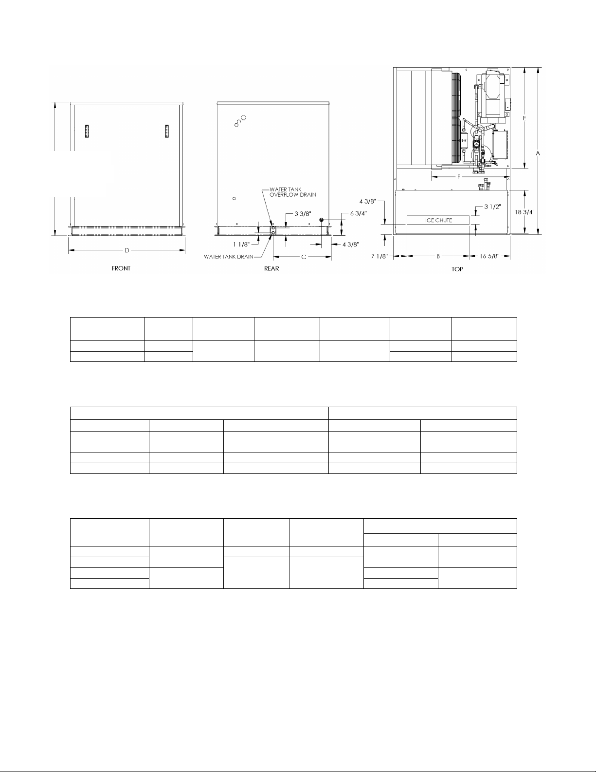
58" - VT40, VT60
& VT80
71" - VT100
Unit "A" "B" "C" "D" "E" "F"
VT40 72 5/8" 27" 24 3/8" 50 3/4" 44" 34"
VT60 89" 39 1/2" 30 1/2" 63 1/4" 57.5 68"
VT80 & VT100 44 7/8" N/A N/A
Model Lowside Condensing Unit Model Skid Mounted
VT40 520 lbs. 975 lbs. VT-40 1,525 lbs.
VT60 650 lbs. 1330 lbs. VT-60 2290 lbs.
VT80 1,475 lbs. 375 lbs. (condenser) VT-80 ----------
VT100 1,850 lbs. 400 lbs. (condenser) VT-100 ----------
Suction Hot Gas Liquid
Model Line Line Line
VT40 1 3/8 OD 7/8 OD 5/8 OD N/A N/A
VT60 1 1/8 OD 7/8 OD
VT80 1 5/8 OD 1 1/8 OD 7/8 OD
VT100 1 3/8 OD
Note: Split systems will be supplied with Rota-lock adapters to connect the highside to the lowside
Machine Clearances:
machine. This will provide sufficient area for service and air flow.
FIGURE 2-1
Ice Machine Dimensions
TABLE 2-1
Ice Machine Dimensions
Remote Weights Skid Mounted Weights
TABLE 2-2
Weight Of Machines
TABLE 2-3
Refrigerant Line Sizes
A minimum three (3) feet of clearance is recommended around entire ice
Remote Condenser
Discharge Liquid Return
Evaporator Installation:
Mount evaporator section (lowside) on storage area capable of sustaining its
weight and secure by thru bolting.
Note: Ambient at the lowside should remain between 50º
not drop below 40º
F. Machine may experience problems if operated outside of these ranges.
F
–105º
F. Makeup wa
ter temperature should
Page 10
Vogt® VT Service Manual 2-3
Installation Instructions
Piping Installation:
Use ACR refrigeration tubing and nitrogen purge during brazing to prevent formation
of copper oxide. For piping runs exceeding 25’, consult a reliable piping manual (Copeland, Heatcraft, or Vilter)
for proper pipe sizing. Heat sink all ball valves and remove Schrader valve core prior to brazing. Pressure test
piping for leaks. Evacuate lines to 500 microns prior to starting machine.
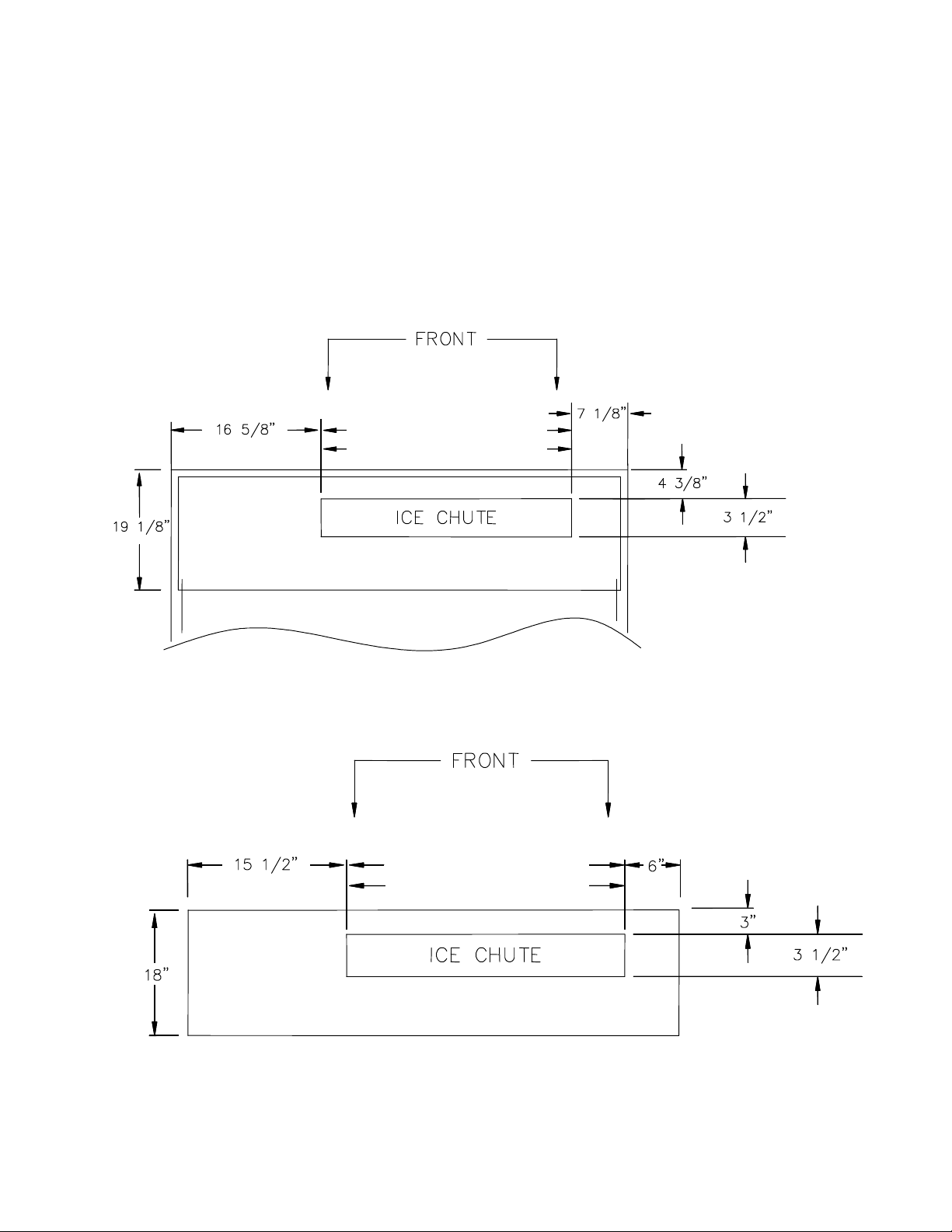
Chute Location:
bin. Place ice machine on ice storage unit and bolt in place. Machine must be level front to back and side
to side for proper operation.
Using drawing and table below, determine ice machine location so that it is centered on
39 1/2” (VT60, VT80 & VT100)
27” (VT40)
Skid Mounted
39 1/2” (VT60, VT80 & VT100)
27” (VT40)
Split System
FIGURE 2-2
Ice Chute Cutout Location
Page 11
2-4 Vogt® VT Service Manual
Installation Instructions
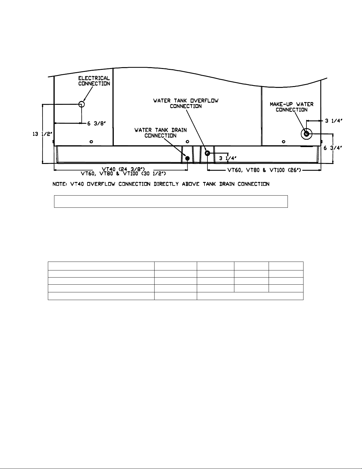
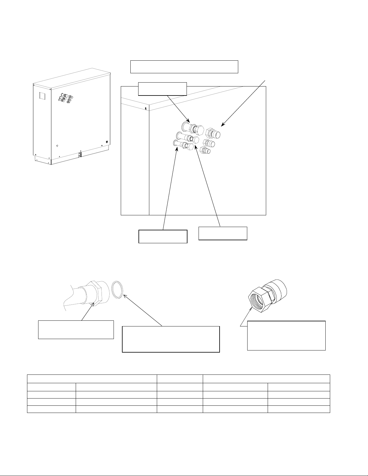
Makeup water, water tank drain and water tank overflow are ½” FPT connections
FIGURE 2-3
VT Lowside Water and Electrical Connections – Rear View
Makeup Water Flow VT40 VT60 VT80 VT100
Usage - Gallons /100 lbs of Ice 12 12 12 12
Flow rate – Gallons / minute 0.38 0.54 0.67 0.80
Flow rate – Gallons / hour 22.5 32.5 40.0 48.0
Water Tank Capacity – Gallons 6 7
Note: Water usage and flow rates base on 70°F water with no blowdown
TABLE 2-4
MakeUp Water Requirements / Flow Rates
Page 12
Vogt® VT Service Manual 2-5
Installation Instructions
Wiring And Electrical Connection.
! WARNING !
Only service personnel experienced in refrigeration and qualified to work with high
voltage electrical equipment should be allowed to install or work on the Vogt® VT
Series Ice machine.
! WARNING !
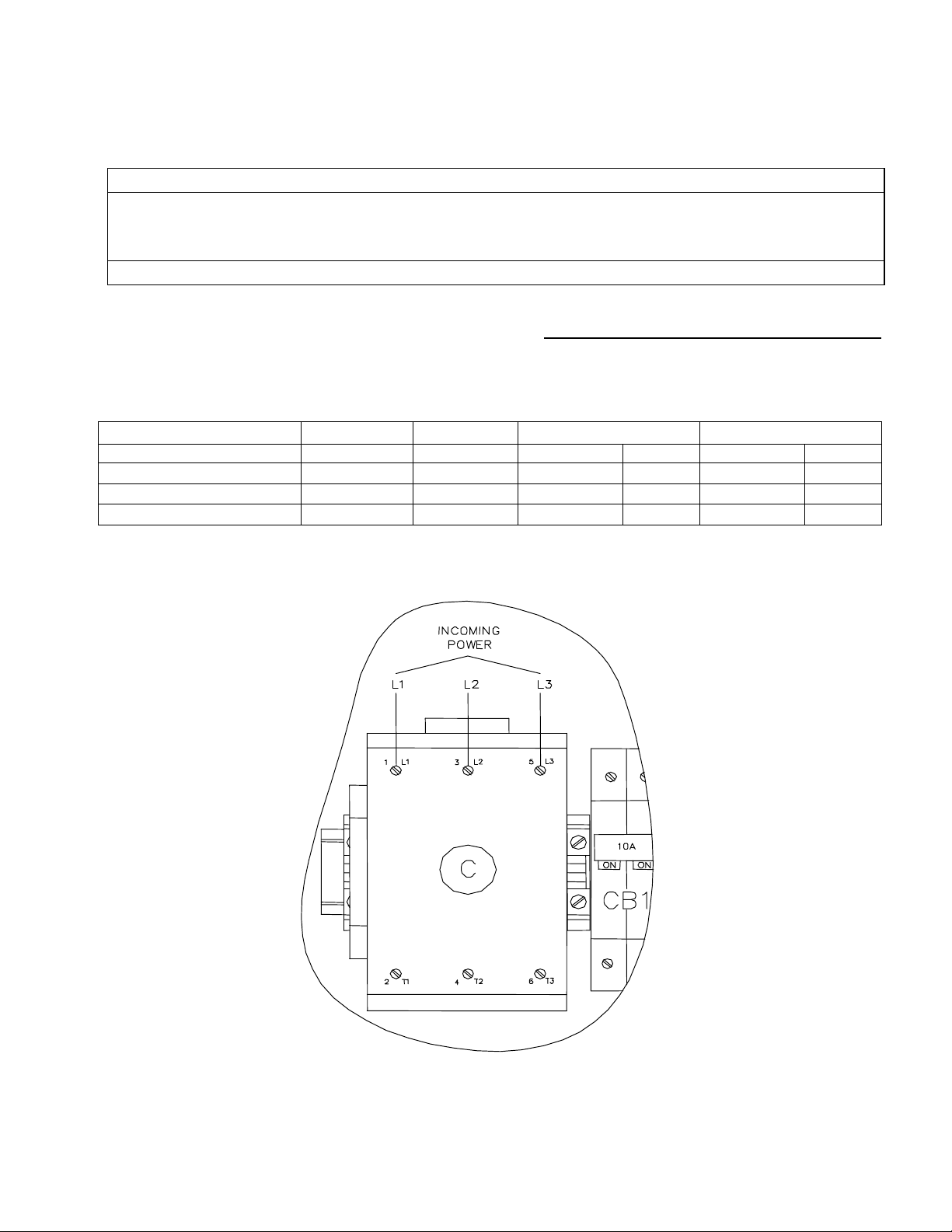
Main Power:
Refer to the table below to properly size wiring connections. A fused disconnect switch must be provided
near the condensing unit of the ice machine. Connect 3 phase power to compressor contactor L1, L2, L3 for
operation of the VT ice machine and its controls. If one phase (leg) of the 3 phase power is higher or lower
(“Wild”), it should be connected to terminal #L2. Connect the “Ground” wire to the “Ground” terminal provided.
Electrical Data VT40 VT60 VT80 VT100
Volts/ Phase/ Hertz
Total F.L.A.
Minimum Circuit Ampacity
Maximum Fuse Size
Power for the entire ice machine will be supplied at the condensing unit.
208/230-3-60 208/230-3-60 208/230-3-60 460-3-60 208/230-3-60 460-3-60
46.1 56.4 67.2 32 80.6 38.7
54.0 66.9 80.4 38.6 97.1 47
85 110 135 65 165 80
TABLE 2-5
Electrical Requirements
FIGURE 2-4
Main Power Connection
Page 13
2-6 Vogt® VT Service Manual
400/460V, 3PH, 50/60HZ
SWIT
CH
CONDENSER
Installation Instructions
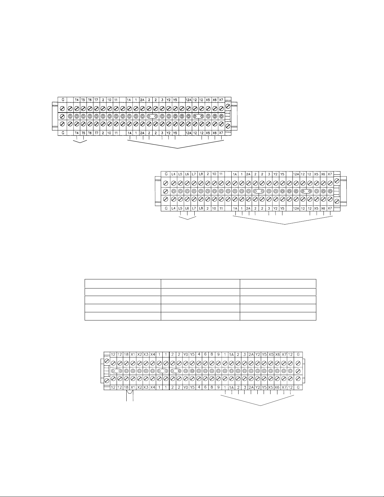
Air Cooled Condenser Wiring:
condensing unit control panel terminal block to the air cooled condenser control panel.
Note: 400/460V VT-80 & VT100’s run 3 #14 AWG wires from terminals L6, L7& L8 to air cooled condenser.
Standard Voltage Machine
200/230V,3PH, 50/60HZ
Run two #14 AWG wires from the terminals T4 and T5 on the
AIR COOLED
CONDENSER
TO LOWSIDE
VT-80 & VT-100
AIR COOLED
TO LOWSIDE
FIGURE 2-5
Condensing Unit Terminal Blocks
Lowside Electrical Connections:
terminal block to the condensing unit (highside) control panel terminal block.
Run 11 #14 AWG or larger wires run from the Lowside control panel
Number of wires Wire Size
5 16 (Red) 1, 2, 3, Y2, Y5
4 16 (Blue) X5, X6, X7, 12
2 14 (Black) 1A, 2A
1 14 (Green) GND
(AWG)
Wire #
Note: Machine is supplied with a remote “on/off” connection on the lowside terminal block. If a remote
TABLE 2-6
Lowside to Highside Wire
REMOTE “ON/OFF”
TO LOWSIDE
FIGURE 2-6
Lowside Unit Terminal Block
“On/Off” switch is used, remove jumper between #18 & #X1 and connect switch to these terminals.
Page 14
Vogt® VT Service Manual 2-7
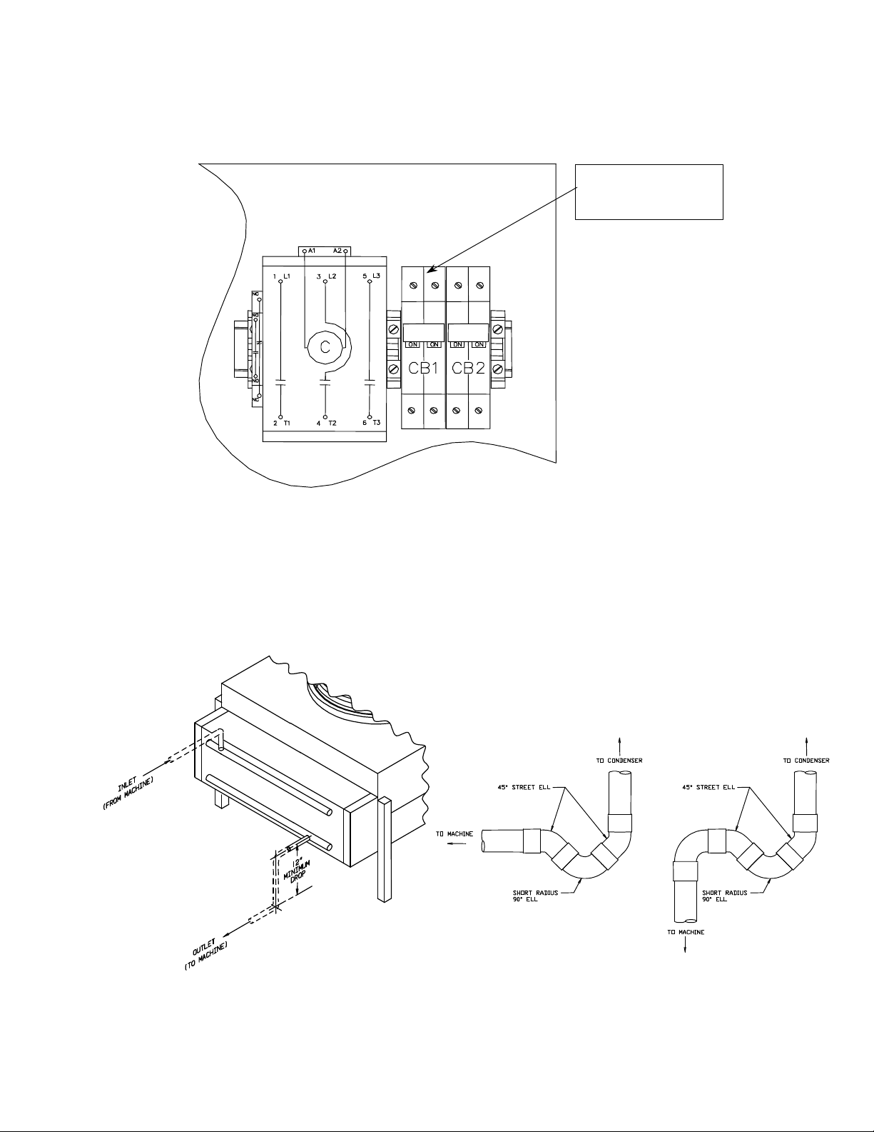
10A 15A
CB1 supplies power
Installation Instructions
Power is supplied to the lowside through circuit breaker (CB1) located in the condensing unit control panel.
See diagram below.
Condensing unit control panel
to lowside unit
FIGURE 2-7
Condensing Unit Circuit Breakers (200/230V)
Air Cooled Condenser Installation (VT80 & VT100):
are trapped internally. A trap leaving the compressor is not necessary. On vertical runs a short radius “P” trap
should be installed every 15’ to 20’ of vertical rise to facilitate oil flow. Horizontal runs should be sloped in
direction of refrigerant flow 1” for every 20’ of run. The condenser should be securely mounted in a place
capable of sustaining its weight.
Ice making systems with remote condensers
FIGURE 2-8
Condenser Piping (VT80 & VT100) and Recommended Traps
Page 15
2-8 Vogt® VT Service Manual
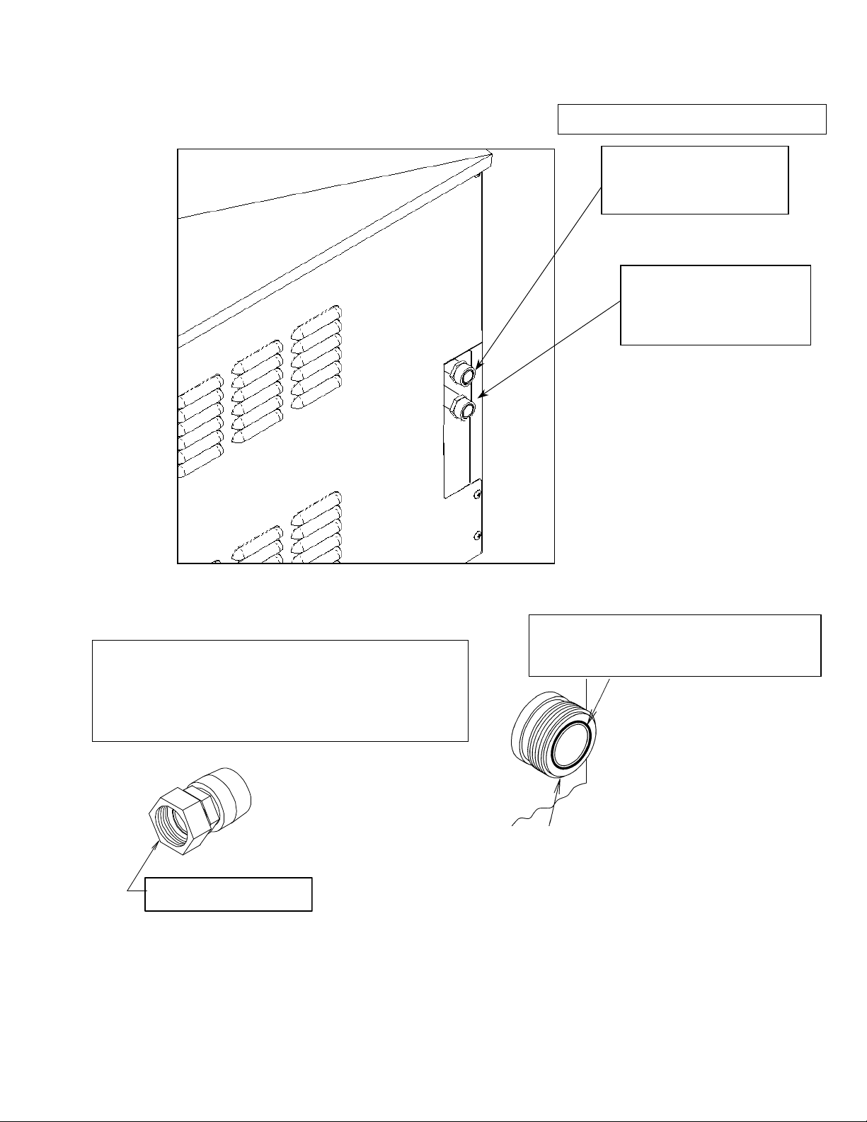
Note: Rota
supplied with machine
Note: Rota
12 F x 7/8” Sweat (Solder)
Installation Instructions
Must solder with 45% silver solder
Female Rota-lock Adapters:
12A2396A0701 – for 1 ¼” (Return Line from condenser)
12A2396A0601 – for 1 ¾”-12 F x 1 3/8” Sweat (Solder)
(Discharge to condenser)
Liquid return from
Teflon Seal
12A2600T01 (for 1 1/4”-12 thread fitting)
12A2600T03 (for 1 3/4”-12 thread fitting)
Air Cooled Condenser
(7/8” line)
Discharge gas to
Air Cooled Condenser
VT80 - 1 1/8”
VT100 – 1 3/8”
Rota-lock Adapter
-lock male
adapter on ice machine
-lock adapters
FIGURE 2-10
VT80 & VT100 Condenser Refrigerant Line Connections
Page 16
Vogt® VT Service Manual 2-9
Installation Instructions
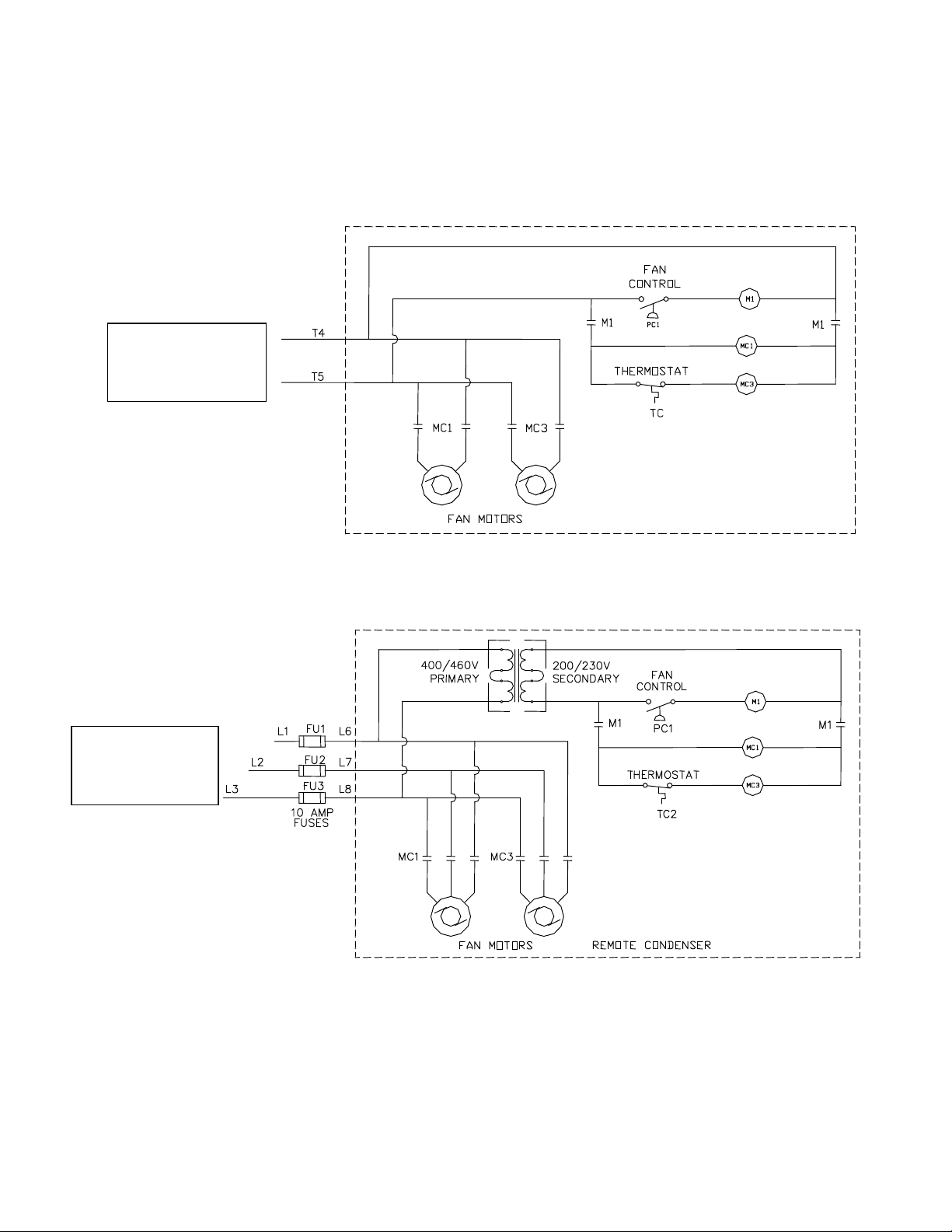
Air Cooled Condenser:
Run two #14 AWG wires and a ground wire from the condensing unit control panel to the Air Cooled
condenser control panel.
To Ice Machines
condensing unit
control panel
To Ice
Machines
condensing unit
VT80 & VT100 Remote Air Cooled Condenser Wiring
The air cooled condenser will be wired to the condensing unit control panel.
208/230V
460V
FIGURE 2-11
Note: Fan control pressure switch is located in air cooled condenser control panel on VT80 & VT100’s with
remote condensers. On VT40’s and VT60’s, fan control pressure switch is location on condensing unit
(highside).
Page 17
2-10 Vogt® VT Service Manual
supplied for both lowside
Must solder w
ith 45% silver
Installation Instructions
Note: Rota-lock fittings
and highside
Suction Line
Liquid Line
Hot Gas Line
FIGURE 2-12
VT Lowside Connections
Rota-lock Fitting
(on lowside & condensing unit)
Teflon Seal
12A2600T01 (for 1 1/4”-12 thread fitting)
12A2600T03 (for 1 3/4”-12 thread fitting)
Rota-lock Adapter
1 3/8” IDS X 1 3/4”-12 Threads
1 1/8” IDS X 1 1/4”-12 Threads
7/8” IDS X 1 1/4”-12 Threads
Rota-lock Adapter Teflon Seal
Part # Description Part # VT40 VT60
12A2396A0501 1 1/8” IDS X 1 1/4”-12Thrd 12A2600T01 N/A Hot Gas Line
12A2396A0601 1 3/8” IDS X 1 3/4”-12Thrd 12A2600T03 Suction Line Suction Line
12A2396A0701 7/8” IDS X 1 1/4”-12Thrd 12A2600T01 Liquid & Hot Gas line Liquid Line
Where Used
Note: See Refrigerant Line Size TABLE 2-3 for line sizes
TABLE 2-5
Rota-lock Adapters
Page 18
Vogt® VT Service Manual 2-11
Installation Instructions
Control Panel
Control Panel
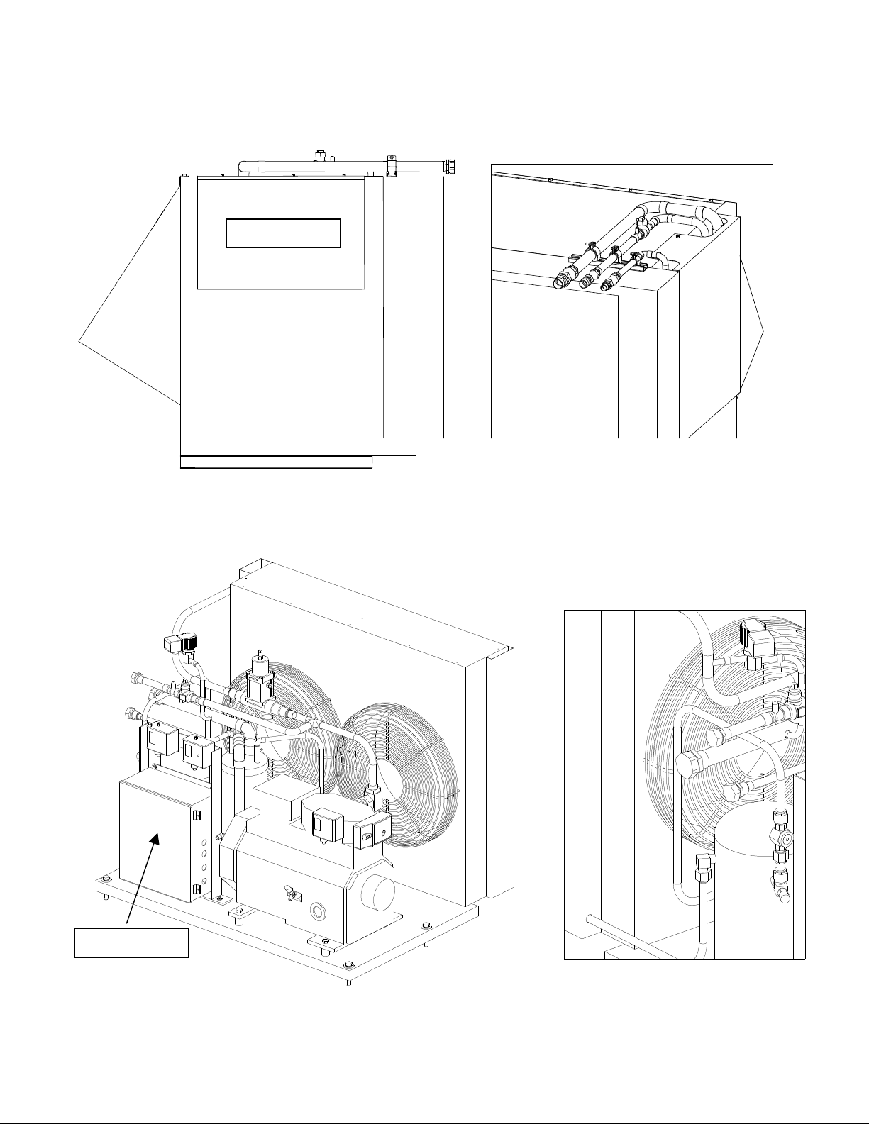
FIGURE 2-13
VT60 Condensing Unit Connections
FIGURE 2-14
VT40 Condensing Unit Connections
Page 19
2-12 Vogt® VT Service Manual
Installation Instructions
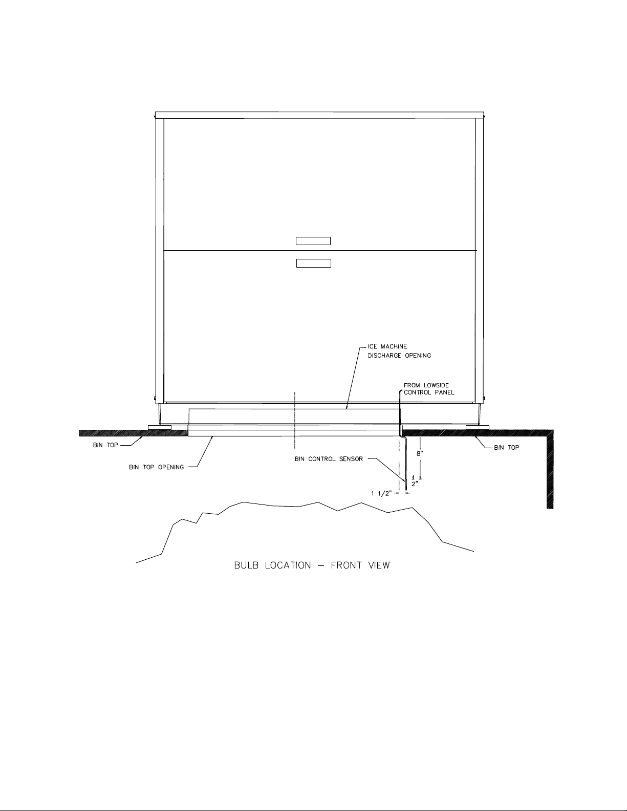
Storing Ice.
The sensor should be mounted on the right side of the bin approximately 8” –12” from the top of the bin.
When storing ice in a bin, make sure the bin control sensor is mounted in the bin properly.
FIGURE 2-15A
Bin Control Sensor Installation
Page 20

Vogt® VT Service Manual 2-13
STAINLESS
NOTE: Use
front of angle to
protect probe
Installation Instructions
STEEL
ANGLE
FIGURE 2-15B
Bin Control Sensor Installation
Ice Bin Capacity.
into a bin, it will pile up and slope naturally at about a 45° angle. This natural slope should be taken into
account when locating the bin thermostat sensor (or other bin level control) and when calculating the normal
bin capacity. If the ice is spread out by hand in the bin for maximum storage capacity, make sure a hazard
is not created by allowing ice to back up into the chute and jamming the cutter. Always allow enough room
below the chute for at least one harvest.
VT40 = 25-30 lbs. / cycle
VT60 & VT80 = 35-40 lbs. / cycle
VT100 = 47-52 lbs. / cycle
Crushed ice weighs approximately 35 pounds per cubic ft. (35 lb/ft3). As ice drops
Page 21

2-14 Vogt® VT Service Manual
Installation Instructions
Blank
Page 22
Vogt® VT Service Manual 3-1
Model Specifications
3. Model Specifications
Electric VT-40 VT-60 VT-80 VT-100
Volts/ Phase/ Hertz 208/230-3-60
Total F.L.A. Rating 46.1 56.4 67.2 80.8
Minimum Circuit Ampacity 54.0 66.9 80.4 97.3
Maximum Circuit Breaker 90 110 135 165
Compressor
Compressor 5.5 HP 7 HP 10 HP 12.5 HP
Voltage Range
Nameplate Amp Rating
Locked Rotor Amp Rating
Oil (Suniso) – Mineral (R22) 3GS
Oil (Copeland) – Synthetic (R404A) Ultra 32 – 3MAF or Mobil EAL Arctic 22 CC
Oil – amount
Chopper Motor
HP 1/2 HP
Voltage 230 V
FLA 3.7 A
Water Pump Motor
Hartell Anjon (CE approved)
HP 1/12 HP 1/5 HP (144W)
Voltage 208-230V 115V
FLA 0.85 A 1.2A
Condenser Fan Motors
HP 2 @1/2 HP
Voltage 208-230 V
FLA (Total for both motors) 8.4 A 8.2 A 8.4 A 8.6 A
Field Connections
Suction 1 3/8 ODS 1 3/8 ODS N/A N/A
Hot Gas 7/8 ODS 1 1/8 ODS 1 1/8 ODS 1 1/8 ODS
Liquid 5/8 ODS 7/8 ODS 7/8 ODS 7/8 ODS
General Info
Sight Glass (Sporlan) SA 15U SA 17S SA 17S SA 17S
Filter Drier (Sporlan) C-415 RC-4864 RC-4864 RC-4864
Refrigerant Charge 16 lbs. 32 lbs. 35 lbs. 40 lbs.
Inlet Water Line ½” FPT
Water Tank Drain & Water Tank Overflow ½” FPT
Control Settings
R22 R404A
Cut-in Cut-out Cut-in Cut-out
Fan Switch (PSIG) 220 200 250 230
Low Pressure Safety (PSIG) 20 10 20 10
Harvest Hold Pressure Control 45 60 65 80
High Pressure Safety (PSIG) Manual 300 Manual 350
Oil Pressure Control (Differential) 9 PSIG (Manual Reset)
Listed refrigerant charges are for close coupled and skid mounted machines as tested.
Remote installations of extended length will require additional refrigerant.
Note: Electrical data based on air cooled units
(Copeland® Discus®)
(208/230)
(Initial Charge / Recharge - oz)
187-253
(RLA)
31.5 42.0 52.6 66
(LRA)
161.0 215.0 278 374
(Marathon)
(Remote Condensing Units Only)
(approximate)
125 / 115 135 / 125
Page 23

3-2 Vogt® VT Service Manual
“RC”
–
Remote Air
"H" – High
-
side
“K” – 12.5HP
"21"
-
230-1-60
Product Variation Codes
Model Specifications
Vogt Ice Vertical Tube
Model Number Structure
G
VT
– P
B
6
F
AC
26
H
Basic Model
“VT” – Vertical Tube
Nominal Capacity
in 1000’s of lbs
“4” – 4000 lbs
“6” – 6000 lbs
“8” – 8000 lbs
“10” – 10000 lbs
Configuration
"P" – Package
"L" – Low-side
Refrigerant
"F" - R22
"H" – R404A
Revision Level
A letter assigned to indicate
major revisions within any one
family series.
Electrical Codes
"26" - 208/230-3-60
"46" - 460-3-60
"25" - 200-3-50
"45" - 400-3-50
“35” – 380-3-50
Condenser
“NC” – No Condenser
"AC" – Air Cooled
"WC" – Water Cooled
“SW” – Sea Water
00
Compressor Size
“0” – No Compressor
“F” – 5 ½HP
“G” – 7HP, 3cyl, 2120 CFH
“H” – 7HP, 4cyl, 2380 CFH
“J” – 10HP
(
A number or letter designator assigned to specific variations within a family.)
“01” – CE Approved, no skins
"00 or Blank" – Standard Product
“NS” – No skins (on condensing unit)
“WS” – With skins (on condensing unit)
“RS” – Remote Start Switch
Skin
(casing)
“G” – Galvannealed
“S” – Stainless Steel
Material
Page 24

Vogt® VT Service Manual 4-1
CAUTION !!! Make sure Lower Evaporator Housing Cover is
!!!
! CAUTION !!!!
Initial Startup
4. Initial Startup
START-UP PROCEDURE
Prior to start-up, the following items should be checked:
1.
Make sure all packing has been removed from the lowside unit. To do this, you must remove the upper
and lower evaporator housing covers. Remove to upper casing first, then the lower. (See Figure 4-1)
put back on machine before power is applied.
2. Open all service and ball valves. (Figure 4-4 & 4-5)
3. Check that bin switch is installed correctly. (Figure 2-5)
4. Check voltage and verify with nameplate.
5. Verify adequate water supply and water level of two (2”) inches.
6. Verify Ice/Off/Clean selector switch on the lowside unit is in the “Off” position.
7. Energize unit two (2) hours prior to starting to energize crankcase heater.
8. Ensure that circuit breakers in condensing unit control panel are in the “on” position. (Figure 4-2)
Note: “Control Power” Light will be ON when power is supplied to Lowside
At completion of above eight (8) items, machine is ready to run. Place selector switch in “Clean” position
and check water flow. (If the pump does not come on, press the green “Manual Harvest” button). Place
selector switch in “Ice” position and press “Manual Harvest” button. The machine will start in a harvest mode
then proceed to the Freeze mode. Observe machine operation. Make no changes to any settings on
machine for six (6) cycles. Verify pressures settings conform to service manual information. Do not trust
pressure control scales.
Never Operate Machine with Lower
Evaporator Housing Cover Removed.
Disconnect Power to machine before
removing lower evaporator cover.
Upper Evaporator
Housing Cover
Lower Evaporator
Housing Cover
FIGURE 4-1
Evaporator Housing Covers (Upper & Lower)
Page 25

4-2 Vogt® VT Service Manual
Selector Switch
Manual Harvest
Lowside unit control panel
CB2
-
Condenser
Fans
Control Circuit Power Light
Initial Startup
Condensing unit control panel
CB1 -
Lowside
Circuit Breakers (200/230V machines)
Light will be “on” if power is being
supplied from the Highside
FIGURE 4-2
(Start)
“Ice / Off / Clean”
FIGURE 4-3
Lowside Control Panel Front
Page 26

Vogt® VT Service Manual 4-3
Initial Startup
VT40
Compressor Discharge
Service Valve
Compressor Suction
Service Valve
VT60
Hot Gas Line Ball Valve
Liquid Line Ball Valve
Receiver Service Valve
Hot Gas Line Ball Valve
Liquid Line Ball Valve
Receiver Service Valve
Compressor Discharge
Service Valve
FIGURE 4-4
Service and Ball Valve Locations
Compressor Suction
Service Valve
Page 27

4-4 Vogt® VT Service Manual
Initial Startup
Compressor Suction
Service Valve
Sight Glass
Compressor Discharge
Service Valve
Service and Ball Valve Locations
VT80 & VT100
FIGURE 4-5
Liquid line Ball Valve
Condenser Ball Valves
(Hot gas & liquid return)
Adding Refrigerant / System Charging:
glass during the ice making cycle. When the fans cycle off, the sight glass should clear in 8 to 10 seconds.
If it takes longer than 10 seconds to clear the glass, the unit is undercharge. Add refrigerant to
system at compressor suction port or the ¼” access fitting on suction line. (See Figure 4-6)
If the glass clears in less than 8 seconds, the unit is overcharged. Remove refrigerant from system
following EPA standards.
Note: Do not charge to a full sightglass. Do not charge in a harvest cycle.
If packaged unit is totally out of refrigerant, add amount specified on machines nameplate.
To charge the system with cycling fans, observe sight
Suction Line – 1/4”
access “T” with
shrader valve
FIGURE 4-6
Access port for adding refrigerant
Page 28

Vogt® VT Service Manual 4-5
VT60
VT40
Initial Startup
Removing Refrigerant:
removed from suction line ¼” access port (See Figure 4-7). For quicker removal, liquid refrigerant may be
reclaimed from the liquid line.
VT80/VT100 – access port on liquid line ball valve
VT60 – access port on receiver rota-lock valve
VT40 – access port in liquid line
To remove refrigerant from an overcharged system, refrigerant gas may be
Note: Follow all EPA regulations and guidelines when handling refrigerant.
Liquid line Ball Valve
VT80 & VT100
with ¼” access port
Receiver Service Valve – rotalock
valve with ¼” access port
Liquid line Ball Valve
with ¼” access port
FIGURE 4-7
Access Fitting for Removing Refrigerant
Page 29

4-6 Vogt® VT Service Manual
Initial Startup
Blank
Page 30

Vogt® VT Service Manual 5-1
Electrical Controls
5. Electrical Controls
CONTROLS
Explanation.
PLC controls the sequence of events and monitors the ice machine functions. The operational sequences of
the VT-Series ice machine can be described best as a series of six different modes. Each mode identifies
and defines a sequence of events that occur while in that mode and thereby cause it to move to the next
mode. Only one mode is active at a time.
Start-Up Mode.
machine at the time of installation, after a power interruption, or after a machine fault. During Start-up, the
machine will not start for two hours. This gives the crankcase heater time to boil any refrigerant out of the
compressor. The start-up mode may be bypassed at any time by pressing the “Manual Harvest” (Start)
button to immediately advance to the standby mode.
NOTE: While the machine is in the Start-Up Mode, the Fault Indicator light will remain “on” (will not be
blinking).
If the power has been turned off to the machine, make sure the compressor
crankcase is warm and there is no liquid refrigerant in with the oil before
The VT-Series ice machine is controlled by a PLC (Programmable Logic Controller). The
The start-up mode is a function which prevents the premature automatic starting of the
! CAUTION !
restarting the unit.
! CAUTION !
Standby Mode.
switches in the control circuit and at the proper time decides which mode to advance to next.
Note: R404A machines are pumped down while in the Standby mode. If the pressure comes back up after
3 minutes, (the low pressure switch “closes”), the machine will go to the Pumpdown Mode.
Freeze Mode (Freeze Cycle).
this time, liquid feed valve is energized (R404A machines only) and the circulating water pump and
compressor are running. The freeze time is determined by the PLC analog timer (0-3.5 min) plus 5 minutes.
(Minimum freeze cycle time = 5 minutes, maximum freeze cycle time = 8.5 minutes)
The standby mode is a decision making mode. It monitors the position of all the various
The freeze mode is active during the normal ice making cycle. During
Freeze cycle Timer (PLC analog pot)
Turn Clockwise to increase freeze time
Minimum Freeze Time = 5 min
Maximum Freeze Time = 8.5 min
PLC: FX1s
PLC: FXos
FIGURE 5-1
PLC – Programmable Logic Controllers
Page 31

5-2 Vogt® VT Service Manual
Electrical Controls
Harvest Mode (Thaw Cycle).
mode. At this time, the circulating water pump stops and the liquid feed valve closes (R404A machines
only). After five seconds, the “D” (thaw gas) solenoid valves open and the chopper motor starts. On split
VT40’s & VT60’s, the hot gas loop valve energizes and VT80 & VT100 the suction stop valve energizes
when the chopper starts and thaw gas valves open. When the suction pressure reaches the set point on the
Harvest Hold (HH) pressure switch (PLC input #2 light will turn “off”), the harvest timer will begin to time.
The harvest timer is an internal timer in the PLC set for 45 seconds.
The harvest mode is terminated by the PLC thaw (harvest) timer at which time the machine will begin
another freeze cycle. The harvest mode can also be terminated manually by pushing in the “Manual Harvest
(Start)” button.
Increasing Harvest Time
(See Figure 5-2) This will increase the time it takes for the suction pressure to reach the set-point on the
switch, thereby increasing the harvest time.
Cut-In Setting
Clockwise – Lowers setting
set @ 45 psi (R22)
set @ 60 psi (R404A)
The harvest mode is normally initiated at the termination of the freeze
– To increase the harvest cycle time, raise the HH pressure switch cut-out setting.
Cut-out Setting
Clockwise – Raises setting
set @ 65 psi (R22)
set @ 80 psi (R404A)
FIGURE 5-2
Harvest Hold Pressure Switch
(located on top of lowside control panel)
Long Harvest Cycle Safety
the HH pressure switch set-point within 3 minutes, the machine will shut down and go to the Fault Mode.
NOTE: If the “Selector Switch” switch is in the “Off” position or the bin control is satisfied the machine will
complete the Freeze, Harvest and Pumpdown cycle before shutting off (standby mode). Machines with R22
do not go through a pumpdown cycle before shutting off.
– The PLC monitors harvest cycle time. If the suction pressure does not reach
Pumpdown Mode
go through a Pumpdown cycle before shutting off. During the Pumpdown cycle the water pump and
compressor are “on” and the liquid feed solenoid valve is “closed”. The machine will run in the Pumpdown
mode until the Low pressure safety switch “opens”. After shutting off on low pressure, the machine will go to
the Standby mode.
Note: If the suction pressure does not reach the cut-out point on the low pressure switch within 2 minutes,
the machine will fault out on a “Pumpdown Fault”.
Continuous Pumpdown
remain pumped down. After a 3 minute delay, if the pressure comes up in the freezer and the low pressure
safety switch “closes” (pressure gets above 20 psig), the compressor will come “on” and pump the machine
down.
(R404A machines only)
(R404A machines only). While in the Standby mode, the machine will
.
All R404A machines have a liquid feed solenoid valve and
Page 32

Vogt® VT Service Manual 5-3
Fault Indicator Light
Flashes to indicate the
Control Circuit Power Light
Light will be “on” if power is being
Electrical Controls
Clean Mode.
During this mode only the water pump will run.
The water pump can be stopped by simply moving the “Selector Switch” from the “Clean” to the “Off”
position. To restart the water pump, move the “Selector Switch” back to the “Clean” position and press the
“Manual Harvest (Start)” button. Ice machine cleaning solution can be circulated though the tubes to
accomplish the cleaning procedure. If the water pump is left to run in the clean mode for more than two
hours, the PLC will shut the machine off. The clean mode can be resumed by pushing the “Manual Harvest”
button.
NOTE: Running in Clean mode for extended period of time can cause excessive pressure to build up in the
freezer.
At the termination of the clean mode, the machine can be returned to ice making mode by putting the
“Selector Switch” in the “Ice” position and pressing the “Manual Harvest” button.
The “Clean” mode is considered to be a maintenance or service function of the machine.
Fault Mode.
aspects of the operation. One of the functions of the PLC is to shut down the machine when a problem
arises and send a signal to the fault indicator light located on the front of the electrical panel. (Figure 5-3)
The red light will blink 1 to 6 times when a problem has caused the machine to shut down.
See table below for the description of the fault modes.
The VT Series is equipped with a PLC (programmable logic controller) that controls all
# Description
1 Low Suction Pressure Auto
2 High Discharge Pressure Manual
3 Low Oil Pressure Manual
4 Long Harvest Cycle N/A
5 Cutter Motor Auto
6 Pumpdown Fault N/A
Solid Power Failure N/A
Switch Reset
(Auto or Manual)
TABLE 5-1
PLC Fault Codes
supplied from the Highside
fault that occurred
FIGURE 5-3
Lowside Control Panel Front
Page 33

5-4 Vogt® VT Service Manual
PLC: FX
s
PLC: FXos
Electrical Controls
PLC Inputs PLC Outputs
#
0 Current Sensing Relay (CSR) for cutter motor
1 “On” Switch & Bin control (in series)
2 Harvest Hold (HH) Pressure Switch
3 Start / Manual Harvest Switch
4 “Clean” Switch
5 High Pressure safety (“off” when tripped)
6 Low Pressure safety (“off” when tripped)
7 Oil Safety / Compressor OL (VT80 & VT100)
1
Description
#
0 Machine Fault Indicator Light
1 Liquid Feed Solenoid (R404A machine only)
2 Compressor
3 N/A
4 Water Pump
5 Cutter / "D" valve / Defrost loop valve or
Suction Stop valve (VT80 & VT100)
Description
FIGURE 5-4
PLC Inputs & Outputs
Page 34

Vogt® VT Service Manual 5-5
Electrical Controls
FIGURE 5-5
Standard Complete Electrical Schematic - 208/230V (Air Cooled)
Page 35

5-6 Vogt® VT Service Manual
Electrical Controls
FIGURE 5-5A
CE Rated VT100 Electrical Schematic – 200-220V / 400-440V (Water Cooled)
Page 36

Vogt® VT Service Manual 5-7
Electrical Controls
FIGURE 5-6
Air Cooled Condenser Wiring (200-240V/400-460V)
Page 37

5-8 Vogt® VT Service Manual
MELSEC FX
OS
-
14MR-ES
Electrical Controls
E-STOP
MITSUBISHI
Lowside Control Panel Parts
BC 12A2117G09 Ice Bin Control
CB3/CB4 12A7515E21 Control Circuit Breaker – 2 pole (3 Amp)
CSR 12A7507S07 Current Sensing Relay (cutter/chopper motor)
CU 12A7516E23 Cutter Motor Contactor
E-STOP 12A7500E75 Contact Block/Mounting Latch, 1NC (CE Machine only)
12A7500E130 Push Button, Push-Pull
P 12A7516E23 Pump Motor Contactor
PB1 12A7500E56 Manual Harvest (Start) Button
12A7500E75 Contact Block, 1 N.O. (for Manual Harvest Button)
PLC 12A7536M01 Programmable Logic Controller
HH 12A2117B03 Harvest Hold Pressure Switch – Open on Rise
SS 12A7500E61 3 Position Selector Switch
12A7500E73 Contact Block, 2 N.O. (for Selector Switch)
TB N/A Terminal Block
1LT 12A7520E33 Machine Fault Indicator Light, 250V, Red
2LT 12A7520E34 Control Power Indicator Light, 250V, Amber
FIGURE 5-7
Lowside Control Panel Layout
Page 38

Vogt® VT Service Manual 5-9
Electrical Controls
FIGURE 5-8
Standard Condensing Unit Electrical Schematic – 208-240V (Air Cooled)
Page 39

5-10 Vogt® VT Service Manual
Electrical Controls
Condensing Unit Control Panel Parts
CB1 12A7515E18 Lowside Circuit Breaker, 2 pole (10Amp)
CB2 12A7515E19 AC Fan motors Circuit Breaker, 2 pole (15Amp)
TB N/A Terminal Block
C 12A7516E29 VT40 Compressor Contactor, 43Amp
12A7516E30 VT60/80/100 Compressor Contactor, 72Amp
12A7518E30 Auxiliary Contact, 1 N.O./1 N.C.
FIGURE 5-8A
Standard 208-240V Condensing Unit Control Panel (Air Cooled)
Page 40

Vogt® VT Service Manual 5-11
Electrical Controls
FIGURE 5-9
CE Rated VT100, 200-220V/400-440V Condensing Schematic (Water Cooled)
Page 41

5-12 Vogt® VT Service Manual
Electrical Controls
PART # DESCRIPTION QTY PART # DESCRIPTION QTY
C 12A7516E29 CONTACTOR, 3 POLE, 43A 1 CB5 12A7515E21 CIRCUIT BREAKER, 2 POLE 1
12A7516E30 CONTACTOR, 3 POLE, 72A * DS 12A2790H07 DISCONNECT HANDLE 1
12A7518E30 AUX CONTACT, 1 NO/1 NC 1 12A2790D07 DISCONNECT, 63A, DOOR MNT 1
CB1 12A7515E18 CIRCUIT BREAKER, 10A, 2 POLE, 1 (400/440V MACH)
(200/220V MACH) 12A2790D11 DISCONNECT, 100A, DOOR MNT
12A7515E35 CIRCUIT BREAKER, 8A, 2 POLE, (200/220V MACH)
(400/440V MACH) FU1- 12A7504E12 FUSE, 10A, 600V, TD, CLASS CC 3
CB2 12A7515E19 CIRCUIT BREAKER, 10A, 2 POLE, 1 FU3 (AC, 400/440V ONLY)
(AC, 200/220V MACH) * PLF 12A7527S06 POWER LINE FILTER, 10A 1
* NOTE: CE UNITS ONLY * TF2 12A7519E38CE TRANS, 250VA, 200/400VAC PRI, 1
120VAC SEC
FIGURE 5-9A
CE Rated VT100, 200-220V/400-440V Condensing Unit Control Panel (Water Cooled)
Page 42

Vogt® VT Service Manual 6-1
Maintenance
6. Maintenance
Preventive Maintenance
For The Manager Who Depends Upon This Machine
For Efficient Operation.
“Preventive Maintenance” simply means that you or a delegated employee makes a daily
visual check of your Vogt Ice machine. Here is what to look for and why:
Daily checklist:
1. Is the machine running or is the bin full
2. Bin doors kept closed
3. Thermostat sensor in bracket
4. Does all ice discharge during harvest
5. Cleanliness
6. Unusual noises
Why?
production of ice for your facility. When you are aware of the proper operating conditions
and observe them on a daily basis, changes in these conditions can alert you to changes
in the operation of the machine which may require maintenance--long before a service
situation arises.
When you make these simple observations on a daily basis, you insure the smooth
Note To Manager or Owner:
The following page is a complete Preventative Maintenance Schedule that should be
performed each 90 days. The Preventative Maintenance page may be copied and given
to your service person. It should be signed, dated, and returned to you for permanent
record.
Page 43

6-2 Vogt® VT Service Manual
Maintenance
Preventive Maintenance Program
Model # _________ Serial # _____________ Date___________
Customer/Address ___________________________________
___________________________________
Mgr. Name _______________ Service Tech Name_____________
The following service performed and checked:
Scale condition of water tank & tubes (good - fair - poor)
All drains freely draining (water tank, drip pan, ice bin)
Ice machine cleaner circulated through system
AC condenser clean (if applicable)
Voltage at machine (actual reading) L1-L2 _____, L2-L3_____, L1-L3______
Compressor amps (halfway through the freeze cycle) L1_____ L2_____ L3_____
Cutter motor amps (cutting ice) _____
Water pump amps _____
AC condenser motor amps (if applicable) _____
Crankcase heater heating
Refrigerant charge (okay - high - low)
Leak checked system ______ leaks found & repaired
Compressor oil level (i.e, 1/4 - 1/2 - 3/4 - low - high)
PSIG, low pressure switch set @ 10 psi
PSIG, high pressure switch set @ 300 psi (R22) / 350 psi (R404A)
Bin stat(s) installed and operate properly
Make-up water float valve adjusted okay
________ _ Suction PSIG at end of freeze
________ Suction PSIG during harvest (high/low)
________ PSIG, Discharge pressure regulator (Water cooled only)
________ Discharge PSIG at end of freeze
________ °F/°C at machine
________ °F/°C outside ambient (at condenser if applicable)
________ °F/°C make-up water temperature
________ Freeze cycle time (minutes)
________ Harvest cycle time (minutes)
________ First ice out (seconds)
________ All ice out (seconds)
________ Pounds of ice per cycle
Capacity check: ice # per cycle X (1440 / total cycle time (min)) = lbs./24 hrs.
Remarks
Last maintenance performed (approx. date) ___/___/___
:
_______________________________________________________
____________________________________________________________
____________________________________________________________
Page 44

Vogt® VT Service Manual 6-3
Suction Screen
Maintenance
Air-Cooled Condenser Cleaning.
the fin face of the condenser. A vacuum cleaner, compressed air, or a brush may be used to remove any
accumulation of loose dirt from the fin section of the condenser.
For the removal of more severe accumulations of dirt or foreign materials, a detergent-type cleaner can be
used. This cleaning agent can be supplied by your local refrigeration supply house. Follow the
manufacturer’s instructions when using a liquid cleaner.
If fins have been damaged, they should be straightened with the proper fin comb.
Compressor Oil.
should be watched carefully for the first hour to make certain the proper lubrication is being maintained. The
oil may become low in the crankcase on an initial start-up if the electrical current has been interrupted to the
machine, thus de-energizing the compressor crankcase heater.
Before starting the machine again, the heater should be energized for a time period of at least two hours to
evaporate refrigerant that may have condensed in the crankcase during the shutdown period. If the oil level
is low after start-up, it should begin to return after a short period of operation.
The oil level should be checked frequently, particularly during the start-up operation, to see that a sufficient
amount of oil remains in the crankcase. While it is important to observe the oil splash during operation, the
true level can be obtained only when the compressor is stopped. With the compressor idle, the oil level
should be between 1/2 to 3/4 of the sight glass, but not above the top of the sightglass.
In starting and charging the unit, the oil sight glass in the crankcase of the compressor
Visual inspection will indicate if dirt is accumulating and clogging
Although the machine was shipped with the oil charge, which was originally added for the test operation, it
may be necessary to add some oil when or if new refrigerant is added to the system.
An oil pump should be used to force any oil that may be required into the system. Oil may be added to the
compressor of all units through the compressor oil charging port. Air should be purged from the oil pump
discharge line by forcing some oil through the line before tightening the charging port.
R22 - Dual Inhibited Suniso 3GS (Viscosity 150) or equal.
R404A - Ultra 32 – 3MAF, Mobil EAL Arctic 22 CC or equal.
See page 3-1 for amount.
Oil Pump
Oil Pump
Oil Sight Glass
Crankcase Heater
Oil Charging valve
FIGURE 6-1
Copeland Discus Compressor (VT80)
Page 45

6-4 Vogt® VT Service Manual
Maintenance
Chopper Gear Reducer Oil.
of a leak. It should be level with the plugged opening in the side of the gear housing. Use Mobile 600W
cylinder oil or equal.
Gear Reducer Vent Plug
The oil level for the gear reducer should be checked if there is evidence
Gear Reducer
FIGURE 6-2
Gear Reducer
Water Distributor.
water supply tube by removing the hose clamp. The water distributor may be soaked in ice machine cleaner.
Make sure all holes are free of dirt and calcium buildup.
At times it may be necessary to clean the plastic water distributor. Remove the
Hose Clamp
1” Tubing
FIGURE 6-3
Water Distributor
Page 46

Vogt® VT Service Manual 7-1
Fault Indicator Light
the
Control Power Light
CB2
-
Condenser Fans
Troubleshooting
7. Troubleshooting
The VT Series ice machine is equipped with a PLC (programmable logic controller) that controls all aspects
of the machines operation. One function of the PLC is to shut down the machine when a machine fault
occurs. By continuously monitoring the High and Low pressure safety switches, the harvest cycle time, and
the oil pressure, the PLC can determine if a problem exists.
Machine Fault Light -
harvest cycle" fault or an oil pressure fault, the machine will not automatically restart. When a "fault" occurs,
the PLC sends a signal to the fault indicator light located on the control panel door.
if the machine shuts off due to a high pressure fault, low pressure fault, a "long
Flashes to indicate
fault that occurred
Is “On” when power is
supplied to
lowside
FIGURE 7-1
Lowside Control Panel Front
# Description Switch Reset
1 Low Suction Pressure
2 High Discharge Pressure
3 Low Oil Pressure
4 Long Harvest Cycle N/A
5 Chopper Motor Fault N/A
6 Pumpdown Fault N/A
Solid Power Failure
Auto
Manual
Manual
N/A
(Auto or Manual)
TABLE 7-1
PLC Fault Codes
Control Power Light – if the machine is shut off and the “Control Power” light on the lowside unit is not
, check the 3A circuit breaker (CB3/CB4) in the lowside control panel. If after resetting the breaker, the
“On”
control light still does not come on, check the 10A breaker (CB1) in the condensing unit control panel.
CB1 -
Lowside
Lowside Unit Control Panel
Condensing Unit Control Panel
FIGURE 7-2
Control Panel
Page 47

7-2 Vogt® VT Service Manual
Troubleshooting
# Description
Inputs 0 Current Sensing Relay (chopper)
1 “On” Selector Switch/Bin Control
2 HH Pressure Switch
3 Manual Harvest (Start) Button
4 Clean Switch
5 High Pressure Safety Switch
6 Low Pressure Safety Switch
7 Oil Safety / Compressor OL
Freeze cycle Timer (PLC analog pot)
Turn Clockwise to increase freeze time
Minimum Freeze Time = 5 min
Maximum Freeze Time = 8.5 min
# Description
(VT80 & VT100)
Outputs
0 Fault Indicator light
1 Liquid Feed Solenoid (R404A machines only)
2 Compressor
3 N/A
4 Water Pump
5 Chopper/Hot Gas Valve/Defrost Loop
or Suction Stop valve (VT80 & VT100)
TABLE 7-2
PLC Inputs/Outputs
PLC Input
Lights
PLC Output
Lights
FIGURE 7-3
PLC (FX
1s
)
Damaged Bin Control Sensor –
control to shut the machine off when the bin is full, one of the first things to check is the Bin Control sensor.
If the sensor is bad or has been damaged, “EP” will be displayed. See 8-3 for more details.
If the machine is not running and it uses the electronic temperature
EP
“EP” on display designates
a damaged
or bad probe
Sensor – can be replaced if damaged
FIGURE 7-3
Electronic Bin Control
Page 48

Vogt® VT Service Manual 7-3
Troubleshooting
MACHINE INOPERATIVE
No Electrical Power:
crankcase heater should be energized two (2) hours prior to starting.
Note: If no power to the lowside unit, check 10A breaker in condensing unit electrical enclosure.
High Pressure Safety:
pressures to determine that compressor discharge pressure is within operating limits. If fans do not come
“on”, check circuit breaker in condensing unit control panel. For water cooled units, verify water supply and
water regulating valve setting.
Low Pressure Safety:
point. If tripped, install gauges observe operating pressures to determine that compressor suction pressure is
within operating limits. If suction pressure is low, check machine refrigerant charge.
Note: When the machine starts after a power failure or after the machine has cycled off on bin control or the
“on/off/clean” selector switch, the PLC do not look at the low pressure switch for 90 seconds.
Compressor Motor Overload Protector
2011)
:
Machines are equipped with a compressor protection device that opens in the event compressor
temperature or amperage reaches an extreme that could damage compressor. The device automatically
resets after compressor has cooled. CoreSense must be reset.
(Note: On VT80 & V100 Only). Note: This sensor is in series with the oil pressure safety switch. Fault #3 can
be either compressor motor overload or oil pressure.
CAUTION: If machine is off on motor overload protector, control cycle timer and
other components will continue to function although the compressor is off. The
machine or any of its components can start without warning causing serious injury.
Bin Control Open:
Faulty Remote Off/On Switch:
Compressor Contactor Defective:
are supplied with power. Check contactor coil for open winding.
Oil Failure Switch
pressure safety switch. Check compressor oil level. If oil level in sightglass, check oil pressure.
Note: Verify proper operation of crankcase heater. Cold starts can cause oil loss.
Chopper Failure:
circuit will detect the absence of motor current and shut the machine off. See Machine “Freeze-Up”.
Check main electrical fused disconnect or circuit breaker. If power has been off,
Reset high pressure control switch. If tripped, install gauges observe operating
This switch will automatically reset when pressure comes up to the “cut-in” set
(Sentronic before March 2011, CoreSense after March
Adjust thermostat bin control as required. See page 8-3 for bin control error code.
Replace if necessary.
Check wiring to line contactor to determine that "L" terminals
(Sentronic before March 2011, CoreSense after March 2011): Reset Sentronic oil
If the chopper motor fails to come on, the current sensing relay in the chopper motor
Page 49

7-4 Vogt® VT Service Manual
CAUTION: Clearing “freeze
-
ups” should be done using only water. Use of
any foreign objects (example: hammer or screw driver) may damage tube
This
Troubleshooting
MACHINE “FREEZE-UP”
The following situations may cause machine “freeze-up”:
1. Harvest hold switch is improperly set
2. Improper fan control setting
3. Low head pressure limiting available gas for defrost
4. Dirty, scratched, or dented evaporator surface
5. Chopper motor or motor contactor defective
6. Interruption of electric service
7. Off on low pressure and reset without clearing tubes.
8. Low pressure safety switch improperly adjusted, causing termination prior to harvest.
9. Loss of water pressure.
10. Defective hot gas solenoid valve.
11. TXV not adjusted properly or functioning properly. Ice freezing too far up tube.
Note: If ice is freezing too high (onto the top flange holding the evaporator) the ice may not drop
from the evaoprator tubing. See page 8-6 for adjusting TXV.
Clearing a “freeze-up can be accomplished by placing “On/Off/Clean” selector switch in the “Clean”
position and circulating water over the tubes.
surface. If tube is dented or scratched, ice will not release properly.
will void the evaporator warranty.
Page 50

Vogt® VT Service Manual 7-5
Troubleshooting
ADDITIONAL TROUBLESHOOTING
Low Suction Pressure - Possible causes include:
1. Evaporators froze up
2. Plugged drier
3. Low refrigerant charge
4. Moisture causing freezing @ TXV
5. Low water circulation
6. Faulty TXV
7. Bad hot gas solenoid valve
High Head Pressure - Possible causes include:
1. Plugged condenser
2. Faulty fan motor
3. Faulty fan cycle switch
4. Faulty thermostat at condenser (allowing only one fan to run)
5. Refrigerant overcharge
6. Non condensable present.
7. Electric interruption to condenser (Remote condenser only)
Compressor Oil Pressure Fault - Possible causes include:
1. Faulty oil pressure sensor or module (Sentronic/CoreSense)
2. Clogged oil pump suction screen
3. Low compressor oil
4. Low compressor superheat
Compressor Runs But Condenser Fan Does Not:
1. Faulty fan cycle switch
2. Faulty fan motor
3. Blocked fan blade
4. Electric interruption to condenser (circuit breaker located in condensing unit control panel)
Compressor Will Not Run, Water Pump Runs:
1. Open compressor overload (on VT-40 & VT-60 only)
2. Defective compressor
3. Faulty compressor contactor
Water Pump Will Not Run, Compressor Runs:
1. Faulty pump
2. Electric service interrupted to pump - pump contactor
Pump and Compressor Run with Insufficient Water on the Evaporators:
1. Water system needs cleaning
2. Faulty pump
3. Inadequate water supply
4. Obstructed float assembly
5. Improper float adjustment
Chopper motor Fault:
1. Bad chopper motor
2. Bad chopper motor contactor
3. Machine Froze up
Page 51

7-6 Vogt® VT Service Manual
Troubleshooting
Blank
Page 52

Vogt® VT Service Manual 8-1
Freeze
Harvest
Service Operations
8. Service Operations
PRINCIPLE OF OPERATION
The Vogt® VT Series line of ice making machines from Vogt® Tube Ice®, LLC, combines state-of-the-art
technology and efficiency with a reputation for quality and reliability developed over four decades of
manufacturing.
In the Vogt® VT Series icemaker, ice is produced on both walls of vertically suspended cylindrical tubes with
recirculating water. As ice is produced, makeup water is fed to the water tank via float valve. Freeze time
and harvest time are controlled by a Programmable Logic Controller (PLC).
In freeze cycle, the liquid feed valve is “open” (R404A machines only) and the compressor and water pump
are “on”. At the end of the Freeze cycle, the PLC initiates the Harvest cycle were the hot gas solenoid
valves and chopper motor are energized, and the water pump is turned “off” and liquid feed valve “closed”.
Bin control or remote on/off switch will allow machine to complete a freeze and harvest cycle prior to
interrupting operation. For R404A machines, the machine will go thru a Pumpdown before cycling off.
FIGURE 8-1
Piping Schematic
Page 53

8-2 Vogt® VT Service Manual
Service Operations
Pressure Switches
High Pressure Safety: 12A2117H01 (Penn)
This switch terminates operation of machine when high compressor discharge pressure occurs.
Settings
Low Pressure Safety: 12A2117B08
This switch terminates operation of machine when low suction pressure occurs.
Note: When the machine starts after a power failure or after the machine has cycled off on bin control or the
“on/off/clean” selector switch, the plc do not look at the low pressure switch for 90 seconds.
Settings
Fan Control Switch:
This switch cycles the condenser fan motors to maintain proper discharge pressure.
Settings
Harvest Hold Switch: 12A2117B03 (Penn)
This switch stops harvest timer (holds machine in harvest) until the suction pressure comes up to the switch
sets set point. Note: In low ambient conditions, the harvest time may be increased by raising the switch Cutout setting to 70-75 psig.
Settings
Cut-out (“Off”) 65 PSIG (R22) / 80 PSIG (R404A)
: Cut-Out (“Off”) 300 PSIG (R22) / 350 PSIG (R404A). Manual Reset
: Cut-out (“Off”) 10 PSIG (R22 & R404A)
Cut-in (“On”) 20 PSIG. (R22 & R404A)
: Cut-in (“On”) 220 PSIG (R22) / 250 PSIG (R404A)
Cut-out (“Off”) 200 PSIG (R22) / 230 PSIG (R404A)
: Cut-In (“On”) 45 PSIG (R22) / 60 PSIG (R404A)
Condenser Fan Control Switch, Low Pressure Safety & Harvest Hold Switch
High Pressure Safety Switch
(Penn)
12A2117F05 (Penn)
/ 12A2117H01CE (Danfoss – for CE machines)
12A2117H01CE - Danfoss switch wiring
FIGURE 8-2A
/ 12A2117B03CE (Danfoss – for CE machines)
/ 12A2117B03CE (Danfoss – for CE machines)
12A2117B03CE - Danfoss switch wiring
FIGURE 8-2B
Page 54

Vogt® VT Service Manual 8-3
Service Operations
Oil Failure Switch:
This device monitors the compressor oil pump differential pressure. If oil pressure drops below 7-9 psig for a
period of two minutes, the Sentronic module will open the control circuit contact and shut the machine off.
Factory set @ 7-9 psig (Manual reset)
CoreSense: Replaces Copeland Sentronic Oil Pressure Safety module on all Discus compressor and the
Electronic Motor Protector module in 4D & 6D compressors. Note: 2D & 3D compressor will still have
Internal Line Break overload protection.
The oil pressure monitoring portion of the CoreSense will act very similar to the Sentronic Oil Pressure
Safety switch. A current transformer (CT) in the compressor junction box determines when the compressor
is running and starts monitoring oil pressure.
The CoreSense module has power applied at all times to allow for more detailed fault notification. An LED
will flash when a fault occurs. The number of flashes will identify the fault condition.
# of Flashes Condition
1 Oil Pressure
2 Motor Protection Trip
3 Discharge Temperature (optional add-on)
4 Current Sensor Fault
5 Communication Error
12A2117A05 (Copeland Sentronic) On compressors manufactured before March 2011.
FIGURE 8-3
Copeland CoreSense
Page 55

8-4 Vogt® VT Service Manual
Service Operations
Bin Control (Ranco Electronic Temperature Control)
With the Ranco electronic temperature control the ice must come in contact with the sensor to shut the
machine off. The sensor should be installed in the bin using the standard bin thermostat mounting bracket.
Three quarters of the sensor (black part) should hang below the bottom of the bracket.
Programming the Sensor
1) Press the “SET” button to enter the sensors setup mode
2) Select between “C”- Celsius and “F” - Fahrenheit
Use the up ▲or down ▼ key to select “F”
3) Press the “SET” button to set the Set point (S1 will be blinking)
Use the up ▲ or down ▼ key to set the temperature at 38
4) Press the “SET” button to set the Differential (DIF 1 will be blinking)
Use the up ▲ or down ▼ key to set the differential at 2
5) Select between “C1”- Cooling mode and “H1” - Heating mode
Use the up ▲ or down ▼ key to select “C1”
Machine will shut off when temperature drops to 38
Note: The sensor will automatically exit the programming mode if no keys are depressed for a period of
thirty seconds. Any settings that have been input to the control will be accepted at that point.
°
F
°
F
°
F and come on when temperature reaches 40°F.
FIGURE 8-4
Electronic Temperature Control - Part # 12A 2117G09
Error Messages
E1 – Appears when either the up ▲ or down ▼ key is pressed when not in the programming mode.
To correct: If the E1 message appears even when no keys are being pressed, replace the control.
E2 – Appears if the control settings are not properly stored in memory.
To correct: Check all settings and correct if necessary.
EP – Appears when the probe is open, shorted or sensing a temperature that is out of range.
To correct: Check to see if the sensed temperature is out of range. If the sensor is subject to
a known ambient temperature between -30
the damaged probe.
EE – Appears if the EEPROM data has been corrupted.
To correct: This condition cannot be field repaired. Replace the control.
ο
F and 220οF, and displays the EP code, replace
Note: Electronic Temperature Control #: 12A2117G09 / Replacement Sensor #: 12A2117G0901
Page 56

Vogt® VT Service Manual 8-5
Service Operations
PLC (Programmable Logic Controller).
(Programmable Logic Controller). The PLC controls the sequence of events and monitors the ice machine
functions. The operational sequences of the VT-Series ice machine can be described best as a series of six
different modes. Each mode identifies and defines a sequence of events that occur while in that mode and
thereby cause it to move to the next mode. Only one mode is active at a time.
The VT-Series ice machine is controlled by a PLC
Freeze cycle Timer (PLC analog pot)
Turn Clockwise to increase freeze time
Minimum Freeze Time = 5 min
Maximum Freeze Time = 8.5 min
FIGURE 8-5
PLC (Programmable Logic Controller)
# Description
Inputs 0
Current Sensing Relay (chopper)
“On” Selector Switch/Bin Control
1
HH Pressure Switch
2
Manual Harvest (Start) Button
3
Clean Switch
4
High Pressure Safety Switch
5
Low Pressure Safety Switch
6
Oil Press Safety /Comp Motor OL
7
# Description
Outputs
0
1
2
3
4
5
Suction Stop Valve (VT80 & VT100)
TABLE 8-1
PLC Inputs/Outputs
Fault Indicator light
Liquid Feed Solenoid (R404A machines only)
Compressor
N/A
Water Pump
Chopper/Hot Gas Valve/Defrost Loop valve or
Page 57

8-6 Vogt® VT Service Manual
Discharge
Service Operations
Service
Valve
Oil Pump
Suction
Service
Valve
Oil Charging Valve
Oil Pump Inlet Screen
Crankcase Heater
Oil Pressure
Safety Switch
Oil Sightglass
FIGURE 8-6
Copeland Discus Compressor (10HP Shown)
Description Refrigerant Vogt # Copeland #
Compressor VT-40 (5 1/2HP) R22 12A2110A117 3DB3F33K0-TFC-100
R404A 12A2110A130 3DB3F33KE-TFC-100
Crankcase Heater 100 W (insert type) 12A7509E12 518-0028-01
Oil Pressure safety switch Sentronic
VT-60 (7 HP) R22 12A2110A110 3DS3F46K0-TFC-100
R404A 12A2110A131 3DS3F46KE-TFC-100
VT-80 (10 HP) R22 12A2110A122 4DL3F63K0-TSK-253
R404A 12A2110A128 4DL3F63KE-TSK-253
VT100 (12 1/2 HP) R22 12A2110A125 4DT3F76K0-TSK-253
R404A 12A2110A129 4DT3F76KE-TSK-253
R22/R404A
12A2117A05 585-1066-02
TABLE 8-2
Compressor / Compressor Parts
Page 58

Vogt® VT Service Manual 8-7
Line
Regulator Valve
Defrost Loop
Valve
Pressure Switch
Service Operations
Defrost (hot gas)
Solenoid Valve
TXV
Flow
Liquid Line
Solenoid
(404A only)
Harvest Hold (HH)
Hot gas to
Condenser
Hot gas to
evaporators
To
Suction
Inlet Pressure
Note: Suction Stop Valve
Defrost loop valve
Suction Stop Valve
used on VT80 & VT100 only
used on Split VT40 & VT60 only
Description
Defrost Solenoid Valve (Hot gas valve) 1/2” Solenoid valve 12A4200A406 Sporlan
Defrost Loop Valve (Split VT40 & 1/2” (N.C.) Rebuild Kit 12A4199V53 Sporlan
VT60) Coil 12A2105C16 Sporlan
Suction Stop Valve – N.O. (VT80 & 1 5/8” Solenoid valve 12A4200A1104 Sporlan
VT100) 1 5/8” (N.O.) Rebuild Kit 12A4199V47 Sporlan
Coil (for N.O. valve) 12A2105C04 Sporlan
Liquid Line Solenoid Valve 5/8” Extended End (VT40) 12A4200A0504 Sporlan
(R404A machines only) 7/8” Standard length, B25S (VT60-100) 12A4200A0707 Sporlan
7/8” valve, B19S (after 4/2011) 12A4200A0708 Sporlan
5/8” (N.C.) Rebuild Kit 12A4199V38 Sporlan
7/8” (N.C.) Rebuild Kit – for B25S valve 12A4199V39 Sporlan
7/8” (N.C.) Rebuild Kit – for B19S valve 12A4199V43 Sporlan
Inlet Pressure Regulator Valve 1 1/8” Regulator valve 12A4200N0903 Parker
TXV R22 Machines 12A4200C0305 Sporlan
R404A Machines VT40, 60 & 80 12A4200C0320 Sporlan
VT100 12A4200C0321 Sporlan
Vogt # Manufacture
TABLE 8-3
TXV, Regulator Valve & Solenoid Valves
Page 59

8-8 Vogt® VT Service Manual
Seal /Locking
Service Operations
Adjusting TXV:
flange. Freezing too high on the evaporator may cause ice to hang up on tubes and not release properly.
To lower ice level, the TXV can be closed by running the stem in. Do this by turning the TXV stem clockwise
as shown below. (looking up at the valve stem)
Note: Close TXV ¼ turn at a time. Observe several cycles before making further changes.
Ice should start forming on the evaporator tubes approximately two inches from the top
Close TXV – clockwise (freeze lower on tubes)
Remove TXV cap
If ice is not freezing high enough on the evaporator tubes, the TXV can be opened by backing the stem out.
Do this by turning the TXV stem counter-clockwise. (looking up at the valve stem)
Note: Check expansion valve inlet strainer before opening valve. Clean strainer if necessary.
Open TXV ¼ turn at a time. Observe several cycles before making further changes.
Expansion Valve
Inlet Strainer
Expansion Valve inlet screen/strainer
can be accessed by removing nut
FIGURE 8-7
Adjusting TXV
Inlet Pressure Regulator:
The purpose of this valve is to maintain head pressure during the harvest cycle. (Set point = 160-170 psig)
This regulator valve is used on the split VT40, split VT60, VT80 and VT100.
Nut
Adjustment Screw
Clockwise – raise pressure set point
Counterclockwise – lower pressure set
point
FIGURE 8-8
Inlet Pressure Regulator
Page 60

Vogt® VT Service Manual 8-9
12A2145VT04
85D02
12A2185D01
Service Operations
VT60, VT80 & VT100 Water Distributor – 12A21
VT40 Water Distributor –
Tubing, 1” ID – 12A4181T04
Float Valve (not shown) – 12A4200H0401
Float Valve Cover, Plastic – 12A2150VT02
VT60, VT80 & VT100 Ice Chute Cover, Plastic – 12A2145VT02
VT40 Ice Chute Cover, Plastic –
FIGURE 8-9
Water Tank Parts
Water Pump – 12A4020H03
(12A4020H03CE for CE approved
Water Pump Cover, Plastic – 12A2150VT01
machine)
Page 61

8-10 Vogt® VT Service Manual
Service Operations
1
5
2
6
3
Bolts welded on Evaporator Housing
Nuts welded on gear reducer bracket
Gear reducer vent plug
4
Description Vogt #
1 Chopper assembly 19T2161C03 (VT60, VT80 &VT100)
19T2161C04 (VT40)
2 Bearing, Nylon/Stainless Ball Bearings 12A2020M19
3 Bracket, for Gear Reducer 19T4001S0740
4 Gear Reducer, 5:1 12A4030R14
5 Motor, ½ HP, 3600 RPM, 56C Face, 208-230V, 1 Phase,
50/60Hz
6 Plate, UHMW, for Gear Reducer Bracket 19T2150VT01
12A2900M0511
(12A2900M0511CE – CE approved)
FIGURE 8-10
Chopper Assembly
Page 62

Vogt® VT Service Manual 8-11
!!!! CAUTION !!!!
Service Operations
VT100 Upper Evaporator housing cover - 1919T4001S0762XL/19T4001S0766
VT60 / VT80 Upper Evaporator housing cover – 19T4001S0762/19T4001S0766
VT40 Upper Evaporator housing cover – 19T4001S0764/19T40001S0766
VT60 / VT80 / VT100 Lower Evaporator housing cover – 19T4001S0763
VT40 Lower Evaporator housing cover – 19T4001S0765
Never Operate Machine with Lower
Evaporator Housing Cover Removed.
Disconnect Power to machine before
removing lower evaporator cover.
FIGURE 8-11
Evaporator Covers
Page 63

8-12 Vogt® VT Service Manual
Service Operations
FIGURE 8-12
Freeze Cycle Schematic
Skid mounted (Package VT40 & VT60)
Page 64

Vogt® VT Service Manual 8-13
Service Operations
FIGURE 8-13
Harvest Cycle Schematic
Skid mounted (Package VT40 & VT60)
Page 65

8-14 Vogt® VT Service Manual
Service Operations
FIGURE 8-14
Freeze Cycle Schematic (w/Defrost Loop Valve)
Split System (VT40 & VT60)
Page 66

Vogt® VT Service Manual 8-15
Service Operations
FIGURE 8-15
Harvest Cycle Schematic (w/Defrost Loop Valve)
Split System (VT40 & VT60)
Page 67

8-16 Vogt® VT Service Manual
Service Operations
FIGURE 8-16
Freeze Cycle Schematic (w/Suction Stop Valve)
(VT80 & VT100)
Page 68

Vogt® VT Service Manual 8-17
Service Operations
FIGURE 8-17
Harvest Cycle Schematic (w/Suction Stop Valve)
(VT80 & VT100)
Page 69

8-18 Vogt® VT Service Manual
Service Operations
Replacement Parts List
Control Panel Components (Low-Side)
Part Number Req’d
12A2117G09 1 ELECTRONIC BIN THERMOSTAT
12A2117G0901 1 ELECTRONIC THERMOSTAT PROBE
12A7500E61 1 A/B SELECTOR SWITCH, 3 POSITION, SS, Ice-Clean-Off Selector Switch
12A7500E73 1 CONTACT BLOCK/MOUNTING LATCH, 2-NO, For Ice-Clean-Off Switch
12A7500E56 1 A/B PUSH BUTTON SWITCH (GREEN), PB1- Manual Harvest/Start Switch
12A7500E75 1 CONTACT BLOCK/MOUNTING LATCH, 1-NO, For Manual Harvest/Start Switch
12A7536M01 1 PROGRAMMABLE CONTROLLER (PLC)
12A7516E23 2 A/B CONTACTOR, 9-AMP, 3-POLE, 208/240V W/1-NO AUX, Cutter or Pump Contactor (CU or P)
12A7515E21 1 CONTROL CIRCUIT BREAKER, 3 AMP, 2-POLE, CB3/CB4
12A2117B03 1 PRESSURE SWITCH (PENN), HH-Harvest Hold Pressure Switch
12A2117B03CE PRESSURE SWITCH (DANFOSS) – CE APPROVED MACHINE
12A7520E33 1 INDICATOR LIGHT, 250V RED LENSE, 1LT-Fault Indicator Light
12A7520E36 INDICATOR LIGHT, 28VDC (SPECIAL)
12A7520E34 1 INDICATOR LIGHT, 250V AMBER LENSE, 2LT-Control Power Indicator Light
12A7537S07 1 CURRENT SENSING RELAY
Control Panel Components (Condensing Unit)
12A7516E29 1 A/B CONTACTOR, 43-AMP, 3-POLE, 208/240V W/1-NO AUX
12A7516E30 1 A/B CONTACTOR, 72AMP, 3-POLE, 208/240V COIL
12A7518E30 1 A/B AUX. CONTACT, 3A, 1 NO/1 NC, (SIDE MOUNT)
12A7515E18 1 PUMP/CUTTER MOTOR CIRCUIT BREAKER, 2-POLE, 10 AMP
12A7515E19 1 CONDENSER FAN CIRCUIT BREAKER, 2-POLE, 15 AMP
12A2117A05 1 SENTRONIC OIL PRESSURE SAFETY CONTROL
12A2117B08 1 LOW PRESSURE CONTROL 20”-100#, 1/4”SAE, 36” CAP TUBE
12A2117H01 1 HIGH PRESSURE CONTROL, 50-450#, 1/4”SAE, 36” CAP TUBE
12A2117F05 1 CONDENSER FAN CONTROL SWITCH
12A2117G09 1 ELECTRONIC BIN THERMOSTAT – Remote condenser for VT80 & VT100 only
12A7519E38CE 1
12A7537S06 1
Chopper Assembly
19T2161C03 1 CHOPPER ASSEMBLY FOR VT60, VT80 & VT100 (B-SERIES)
19T2161C04 1 CHOPPER ASSEMBLY FOR VT40 (B-SERIES)
12A2020M19 1 BEARING, NYLON/STAINLESS STEEL BALL BEARING 1” BORE
12A4030R14 1 GEAR REDUCER, GROVE 5:1 RATIO
12A2900M0511
12A2900M0511CE CHOPPER MOTOR, 1/2HP, 3600 RPM, 220V, 50HZ–1PHASE – For CE Approve Machine
Circulating Water
12A4200H0401 1 FLOAT VALVE, ½” ROBERTS #RM214
12A4020H03 1 PUMP, HARTELL, 1/12HP, 208-230V, 50/60HZ
12A4020H03CE PUMP, ANJON, 1/5HP (144W), 115V, 50/60HZ – For CE Approved Machine
12A4181T04 6 TUBING, TYGON B-44-3, 1-1/4" OD x 1" ID
12A2185D01 1 WATER DISTRIBUTOR FOR VT40
12A2185D02 1 WATER DISTRIBUTOR FOR VT60, VT80 & VT100
12A2150VT01 1 WATER PUMP COVER FOR VT (B-SERIES)
12A2150VT02 1 WATER FLOAT VALVE COVER FOR VT (B-SERIES)
12A2145VT02 1 ICE CHUTE COVER FOR VT60, VT80 & VT100 (B-SERIES)
12A2145VT04 1 ICE CHUTE COVER FOR VT40 (B-SERIES)
Description
C-Compressor Motor Contactor for VT40
C-Compressor Motor Contactor for VT60, VT80 & VT100
Auxiliary Contact for Compressor Contactor, VT60, VT80 & VT100
CB1-Control Circuit (Low-Side)
CB2-Control Circuit (Condensing Unit)
(Condenser Fan Cold Weather Thermostat)
TRANSFORMER, 250VA, 400/200V PRI/120V SEC, 50/60HZ, FOR 120V WATER PUMP,
FOR CE APPROVED MACHINE
POWER LINE FILTER, 10A, For CE Approve Machine
CHOPPER MOTOR, 1/2 HP, 3600 RPM, 115/230V-1PHASE
1
Replaces Beckett, Pump #12A4020B01
Circulating Water Tubing (Priced per Ft.)
Page 70

Vogt® VT Service Manual 8-19
Service Operations
Liquid Line
Part Number
12A4200C0305 2 or 3 R22 - EXPANSION VALVE, SPORLAN, 2 for VT40, 3 for VT60, VT80 & VT100
12A4200C0320 2 or 3 R404A - EXPANSION VALVE, SPORLAN, 2 for VT40, 3 for VT60 & VT80
12A4200C0321 3
12A4200A0504 1 SOLENOID VALVE, 5/8” ODC, Normally Closed, Sporlan, 208/230V COIL (Liquid Feed)
VT40 (R404A only)
12A4199V38 REPAIR KIT FOR 5/8" SPORLAN Solenoid Valve, B14S2 OR E10S2
12A4200A0707 1 SOLENOID VALVE, 7/8” ODC, Normally Closed, Sporlan, 208/230V COIL (Liquid Feed) – B25S
12A4200A0708 SOLENOID VALVE, 7/8” ODC, Normally Closed, Sporlan, 208/230V COIL (Liquid Feed) – B19S
(AFTER 4/2011) VT60, VT80 & VT100 (R404A only)
12A4199V39 REPAIR KIT FOR 7/8" SPORLAN Solenoid Valve, B25S2 OR E25S2
12A4199V43 REPAIR KIT FOR 7/8" SPORLAN Solenoid Valve, B19S2 OR E19S2
12A2625S02 1 LIQUID INDICATOR, 7/8" ODC, VT60, VT80 & VT100
12A2625S03 1
12A2140C01 1 FILTER DRIER CORE, VT60, VT80 & VT100
12A2195D28 1
12A2000A07 1 SUCTION ACCUMULATOR, 1-5/8" x 3/4" (After 5/2005)
12A2000A12 SUCTION ACCUMULATOR, 2-1/8" x 7/8"
Thawing Gas Line
12A4200A0406 1 SOLENOID VALVE, 1/2" ODC, Normally Closed SPORLAN, 208/230V COIL (Hot Gas valve)
12A4199V53 1 REPAIR KIT FOR 1/2" SPORLAN ME10S2 OR E10S2
12A2105C16 1 COIL, #MKC-2 FOR SPORLAN 208/240V-50/60HZ
Condensing Unit
12A2110A117 1 VT40 – COMPRESSOR (R22), 3DB3F33K0-TFC-100, 208/230-3-60, 5.5HP
12A2110A130 (R404A), 3DB3F33KE-TFC-100, 208/230-3-60, 5.5HP
12A2110A110 1 VT60 – COMPRESSOR (R22), 3DS3F46K0-TFC-100, 208/230-3-60, 7HP
12A2110A131 (R404A), 3DS3F46KE-TFC-100, 208/230-3-60, 7HP
12A2110A122 1 VT80 – COMPRESSOR (R22), 4DL3F63K0-TSK-253, 208/230/400/460, 10HP
12A2110A128 (R404A), 4DL3F63KE-TSK-253, 208/230/400/460, 10HP
12A2110A125 1 VT100 – COMPRESSOR (R22) 4DT3F76K0-TSK-200, 208/230/400/460, 12.5HP
12A2110A129 (R404A) 4DT3F76K0-TSK-200, 208/230/400/460, 12.5HP
12A7509E12 1 CRANKCASE HEATER, 100 WATT INSERTION
12A2117A05 1 SENTRONIC OIL PRESSURE SAFETY CONTROL
12A2117A0501 1 SENTRONIC OIL PRESSURE SENSOR
12A4200N0903 1
12A4200A0406 1 SOLENOID VALVE, 1/2" ODC, Normally Closed, SPORLAN, 208/230V COIL (Defrost Loop valve)
Split VT40 & VT60
12A4199V53 1 REPAIR KIT FOR 1/2" SPORLAN ME10S2 OR E10S2
12A2105C16 1 COIL, #MKC-2 FOR SPORLAN 208/240V-50/60HZ
12A4200A1104 1 SOLENOID VALVE, 1 5/8" ODC, Normally Open, SPORLAN, 208/230V COIL (Suction Stop valve)
VT80 & VT100
12A4199V47 1 REPAIR KIT FOR 1 5/8" SPORLAN Normally Open valve
12A2600S06 1 GASKET, INLET SIDE OF HSE-15 CONDENSER – For Water Cooled
12A2600S07 1 GASKET, RETURN SIDE OF HSE-15 CONDENSER – For Water Cooled
12A2115A0103CE 1 WATER COOLED CONDENSER, (CE APPROVED) – For Water Cooled, CE Machine
12A4200E1001 1 WATER REGULATING VALVE – For Water Cooled Machine
Req'd
R404A - EXPANSION VALVE, SPORLAN, VT100
LIQUID INDICATOR, 5/8" SAE, VT40
DRIER, FILTER, SPORLAN, VT40
Replaces Bolt-on Heater
INLET PRESSURE REGULATOR, 1 1/8” (VT80’s & VT100’s or VT40 & VT60 split system)
Hot gas loop valve
Description
TABLE 8-4
Replacement Parts List
Page 71

8-20 Vogt® VT Service Manual
Service Operations
Blank
Page 72

Vogt® VT Service Manual 9-1
Additional Product Information
9. Additional Product Information
Power Monitor
Wagner Model #: DTP-3
All Vogt Tube-Ice machine models are available from the factory with a three phase line voltage
power monitor with LCD display. The units are also available for after market or retrofit installation.
These units monitor line voltage inputs from 190 to 610 volts and provide protection against line
voltage variances which can damage or destroy the compressor motor. Features include automatic
system shutdown and restart based on current line conditions, a voltmeter, and a non-volatile
system memory so settings are retained even if power is lost. If machine is ordered with this option
the power monitor can be factory set to customer specifications. The Vogt Part number for a power
monitor retrofit kit is 12A7700K01.
The Display
The display normally shows the AB BC CA line voltages.
If the unit is waiting on a timer, that timer will be displayed. The timer display may be switched off by
pressing SELECT. The LCD will then display the normal AB BC CA line voltage pairs.
Pressing the SELECT button once shows the contactor load side voltages (if the load side option is
connected). The display automatically returns to the display of line side voltage after a few seconds.
Press the Select button to step through the parameters. As you step through the parameters, the
selected parameter will flash. Use the up and down arrow keys to adjust to the desired operating value.
Parameter
Line Side Voltage
Over Voltage
Under Voltage
Phase Unbalance
Lockout Time
Delay Time
Response Time
(Delay on Make)
Control Mode
Contactor Test
(Nominal Voltage)
(tolerance)
(tolerance)
(Delay on Break)
(Delay on Fault)
Parameter limits
Minimum Maximum Default Recommended
0.1 20
90 650
6 18
6 18
2 25
0.1 25
0 30
Off / Auto / On
OFF 5
Settings
208 Supply voltage
12 10
12 10
6 5
0.5 120
0 0
2 2
Auto On
OFF OFF
Unit
Volts
%
%
%
Seconds
Seconds
Seconds
N/A
Volt Diff
Page 73

9-2 Vogt® VT Service Manual
Additional Product Information
Parameters adjustment (in order of display)
Active display of Line Voltage (this is the default normal display)
Active display of Load Side Voltage (if connected)
Voltage Set Point
(VAC Flashes) The value may be adjusted by pressing the up and down arrows. This may be set to the
normal operating voltage of the device being protected in one volt increments.
Under/over Voltage Tolerance in %
(UNDERVOLTAGE/OVERVOLTAGE flashes)
The value may be adjusted by pressing the up and down arrows.
Imbalance Voltage Tolerance in %
(% IMBALANCE flashes) The value may be adjusted by pressing the up and down arrows.
Lockout Time in seconds
(SECONDS flashes) The value may be adjusted by pressing the up and down arrows. (This is the delay on
break timer value)
Delay time in seconds and tenths of seconds
(RESP. SECONDS flashes) The value may be adjusted by pressing the up and down arrows. This is the time
that a fault is allowed before shutdown occurs.
Control mode
(ON OFF AUTO flashes) The value may be adjusted to OFF (load will not turn on), ON (load will turn on
whenever there are not faults and timers are finished) and AUTO (Load will turn on when there is a control
input).
Contactor fault monitor mode
(CONTACTOR FAULT flashes) This option allows you to monitor the contactor and lock it out if the line
voltage and load side varies by more than 5 volts. Pressing the up and down arrows selects off (default) or on.
The load side of the contactor must be connected to the load terminals of the DTP-3 to use this option.
Display of fault memories
(MEM flashes) Pressing up or down displays the last fault conditions that took the unit off line. The first 25
faults are recorded. The top number displayed represents the fault memory. The middle number
represents the total number of faults that have occurred since the fault memory was cleared.
To clear the memory, press and hold the up and down keys until the display is cleared.
Notes
If you press SELECT and do not change a parameter by pressing the up or down arrow keys, the
DTP-3 automatically returns to displaying the line voltage in a few seconds.
The new settings are saved in permanent memory when the display returns to displaying the line
voltage. The new settings may be verified by pressing the select button to sequence through the
various parameters.
To prevent tripping on a 1 volt change, the DTP-3 automatically calculates cut-in voltages for the
return from undervoltage conditions. The cut-out voltage is always based on user voltage and
tolerance settings, while the cut-in voltage is 3% closer to the nominal voltage setting. This quality
is sometimes referred to as hysterisis. This is to help reduce oscillation that may occur on weak
power distribution system. When the load is switched off due to undervoltage, the line voltage will
increase. Without the hystersis, the monitor would switch the load back on, the line voltage would
again drop, and cause a continuous on-off-on cycling.
Page 74

Vogt® VT Service Manual 9-3
Remote Panel
CE Approve Remote Panel
Additional Product Information
Remote Switch Box
VT Remote Switch Box (Optional)
This small control panel (box) consists of Ice/Off/Clean selector switch, a Manual Harvest/Start button and two
indicator lights (power & fault) and can be added to any VT machine. This panel will contain both 208/230VAC
and 24VDC. Remote switch box for CE approved machines will have an Emergency Stop button.
Standard
Remote Switch Box Parts
R-PB1 12A7500E56 PUSH BUTTON, MOMENTARY, GREEN
12A7500E75 CONTACT BLOCK, 1 N.O. W/MOUNTING LATCH
R-PB2 12A7500E130 E-STOP, PUSH-PULL, RED (CE MACHINE ONLY)
12A7500E76 CONTACT BLOCK, 1 N.C. W/MOUNTING LATCH (CE MACHINE ONLY)
R-SS 12A7500E61 3 POS. SELECTOR SWITCH OPERATOR
12A7500E73 CONTACT BLOCK, 2 N.O. W/MOUNTING LATCH
R-1LT 12A7520E33 INDICATOR LIGHT, 250V, RED LENSE
R-2LT 12A7520E34 INDICATOR LIGHT, 250V, AMBER LENSE
PART # DESCRIPTION
FIGURE 9-1
Remote Switch Box Layout
Page 75

9-4 Vogt® VT Service Manual
Additional Product Information
FIGURE 9-2A
Standard Electrical Schematic - 208/230V (With Remote Switch Box)
Page 76

Vogt® VT Service Manual 9-5
Additional Product Information
FIGURE 9-2B
CE Approved Electrical Schematic - 208/230V (With Remote Switch Box)
 Loading...