

Page 1

vShield Administration Guide
vShield Manager 5.1
vShield App 5.1
vShield Edge 5.1
vShield Endpoint 5.1
This document supports the version of each product listed and
supports all subsequent versions until the document is replaced
by a new edition. To check for more recent editions of this
document, see http://www.vmware.com/support/pubs.
EN-000867-01
Page 2

vShield Administration Guide
You can find the most up-to-date technical documentation on the VMware Web site at:
http://www.vmware.com/support/
The VMware Web site also provides the latest product updates.
If you have comments about this documentation, submit your feedback to:
docfeedback@vmware.com
Copyright © 2010 – 2012 VMware, Inc. All rights reserved. This product is protected by U.S. and international copyright and
intellectual property laws. VMware products are covered by one or more patents listed at
http://www.vmware.com/go/patents.
VMware is a registered trademark or trademark of VMware, Inc. in the United States and/or other jurisdictions. All other marks
and names mentioned herein may be trademarks of their respective companies.
VMware, Inc.
3401 Hillview Ave.
Palo Alto, CA 94304
www.vmware.com
2 VMware, Inc.
Page 3

Contents
vShield Administration Guide 7
Overview of vShield 9
1
About vShield Components 9
Migration of vShield Components 11
About VMware Tools on vShield Components 11
Ports Required for vShield Communication 11
vShield Manager User Interface Basics 13
2
Log in to the vShield Manager User Interface 13
About the vShield Manager User Interface 14
Management System Settings 17
3
Edit DNS Servers 17
Edit the vShield Manager Date and Time 18
Edit Lookup Service Details 18
Edit vCenter Server 18
Specify Syslog Server 19
Download Technical Support Logs for vShield 19
Add an SSL Certificate to Identify the vShield Manager Web Service 20
Add a Cisco Switch to vShield Manager 21
Working with Services and Service Groups 21
Grouping Objects 24
VMware, Inc.
User Management 31
4
Configure Single Sign On 31
Managing User Rights 32
Managing the Default User Account 33
Add a User Account 33
Edit a User Account 35
Change a User Role 35
Disable or Enable a User Account 36
Delete a User Account 36
Updating System Software 37
5
View the Current System Software 37
Upload an Update 37
Backing Up vShield Manager Data 39
6
Back Up Your vShield Manager Data on Demand 39
Schedule a Backup of vShield Manager Data 40
3
Page 4

vShield Administration Guide
Restore a Backup 40
System Events and Audit Logs 43
7
View the System Event Report 43
vShield Manager Virtual Appliance Events 43
vShield App Events 44
About the Syslog Format 45
View the Audit Log 45
VXLAN Virtual Wires Management 47
8
Preparing your Network for VXLAN Virtual Wires 48
Create a VXLAN Virtual Wire 49
Connect Virtual Machines to a VXLAN Virtual Wire 51
Test VXLAN Virtual Wire Connectivity 52
Viewing Flow Monitoring Data for a VXLAN Virtual Wire 53
Working with Firewall Rules for VXLAN Virtual Wires 53
Prevent Spoofing on a VXLAN Virtual Wire 54
Editing Network Scopes 54
Edit a VXLAN Virtual Wire 55
Sample Scenario for Creating VXLAN Virtual Wires 56
vShield Edge Management 61
9
View the Status of a vShield Edge 62
Configure vShield Edge Settings 62
Managing Appliances 62
Working with Interfaces 64
Working with Certificates 67
Managing the vShield Edge Firewall 70
Managing NAT Rules 75
Working with Static Routes 77
Managing DHCP Service 78
Managing VPN Services 80
Managing Load Balancer Service 135
About High Availability 140
Configure DNS Servers 141
Configure Remote Syslog Servers 142
Change CLI Credentials 142
Upgrade vShield Edge to Large or X-Large 142
Download Tech Support Logs for vShield Edge 143
Synchronize vShield Edge with vShield Manager 143
Redeploy vShield Edge 144
Service Insertion Management 145
10
Inserting a Network Services 145
Change Service Precedence 148
Edit a Service Manager 148
Delete a Service Manager 149
Edit a Service 149
4 VMware, Inc.
Page 5

Delete a Service 149
Edit a Service Profile 149
Delete a Service Profile 150
Contents
vShield App Management 151
11
Sending vShield App System Events to a Syslog Server 151
Viewing the Current System Status of a vShield App 152
Restart a vShield App 152
Forcing a vShield App to Synchronize with the vShield Manager 152
Viewing Traffic Statistics by vShield App Interface 153
Download Technical Support Logs for vShield App 153
Configuring Fail Safe Mode for vShield App Firewall 153
Excluding Virtual Machines from vShield App Protection 153
vShield App Flow Monitoring 155
12
Viewing the Flow Monitoring Data 155
Add or Edit App Firewall Rule from the Flow Monitoring Report 158
Change the Date Range of the Flow Monitoring Charts 159
vShield App Firewall Management 161
13
Using App Firewall 161
Working with Firewall Rules 163
Using SpoofGuard 168
vShield Endpoint Events and Alarms 173
14
View vShield Endpoint Status 173
vShield Endpoint Alarms 174
vShield Endpoint Events 174
vShield Endpoint Audit Messages 175
vShield Data Security Management 177
15
vShield Data Security User Roles 177
Defining a Data Security Policy 178
Editing a Data Security Policy 180
Running a Data Security Scan 180
Viewing and Downloading Reports 181
Creating Regular Expressions 182
Available Regulations 182
Available Content Blades 197
Supported File Formats 216
Troubleshooting 221
16
Troubleshoot vShield Manager Installation 221
Troubleshooting Operational Issues 222
Troubleshooting vShield Edge Issues 223
Troubleshoot vShield Endpoint Issues 225
Troubleshooting vShield Data Security Issues 226
VMware, Inc. 5
Page 6

vShield Administration Guide
Index 229
6 VMware, Inc.
Page 7

vShield Administration Guide
The vShield Administration Guide describes how to install, configure, monitor, and maintain the VMware
vShield™ system by using the vShield Manager user interface, and the vSphere Client plug-in. The information
includes step-by-step configuration instructions, and suggested best practices.
Intended Audience
This manual is intended for anyone who wants to install or use vShield in a VMware vCenter environment.
The information in this manual is written for experienced system administrators who are familiar with virtual
machine technology and virtual datacenter operations. This manual assumes familiarity with VMware
Infrastructure 5.x, including VMware ESX, vCenter Server, and the vSphere Client.
®
VMware, Inc.
7
Page 8

vShield Administration Guide
8 VMware, Inc.
Page 9

Overview of vShield 1
VMware® vShield is a suite of security virtual appliances built for VMware vCenter Server and VMware ESX
integration. vShield is a critical security component for protecting virtualized datacenters from attacks and
helping you achieve your compliance-mandated goals.
This guide assumes you have administrator access to the entire vShield system. The viewable resources in the
vShield Manager user interface can differ based on the assigned role and rights of a user, and licensing. If you
are unable to access a screen or perform a particular task, consult your vShield administrator.
n
About vShield Components on page 9
vShield includes components and services essential for protecting virtual machines. vShield can be
configured through a web-based user interface, a vSphere Client plug-in, a command line interface (CLI),
and REST API.
n
Migration of vShield Components on page 11
The vShield Manager and vShield Edge virtual appliances can be automatically or manually migrated
based on DRS and HA policies. The vShield Manager must always be up, so you must migrate the vShield
Manager whenever the current ESX host undergoes a reboot or maintenance mode routine.
n
About VMware Tools on vShield Components on page 11
Each vShield virtual appliance includes VMware Tools. Do not upgrade or uninstall the version of
VMware Tools included with a vShield virtual appliance.
n
Ports Required for vShield Communication on page 11
About vShield Components
vShield includes components and services essential for protecting virtual machines. vShield can be configured
through a web-based user interface, a vSphere Client plug-in, a command line interface (CLI), and REST API.
To run vShield, you need one vShield Manager virtual machine and at least one vShield App or vShield Edge
module.
vShield Manager
The vShield Manager is the centralized network management component of vShield and is installed from OVA
as a virtual machine by using the vSphere Client. Using the vShield Manager user interface, administrators
install, configure, and maintain vShield components. A vShield Manager can run on a different ESX host from
your vShield App and vShield Edge modules.
The vShield Manager leverages the VMware Infrastructure SDK to display a copy of the vSphere Client
inventory panel.
For more on the using the vShield Manager user interface, see Chapter 2, “vShield Manager User Interface
Basics,” on page 13.
VMware, Inc.
9
Page 10

vShield Administration Guide
vShield Edge
vShield Edge provides network edge security and gateway services to isolate the virtual machines in a port
group, vDS port group, or Cisco® Nexus 1000V. The vShield Edge connects isolated, stub networks to shared
(uplink) networks by providing common gateway services such as DHCP, VPN, NAT, and Load Balancing.
Common deployments of vShield Edge include in the DMZ, VPN Extranets, and multi-tenant Cloud
environments where the vShield Edge provides perimeter security for Virtual Datacenters (VDCs).
NOTE You must obtain an evaluation or full license to use vShield Edge.
Standard vShield Edge
Services (Including
n
Firewall: Supported rules include IP 5-tuple configuration with IP and port
ranges for stateful inspection for TCP, UDP, and ICMP.
vCloud Director)
n
Network Address Translation: Separate controls for Source and
Destination IP addresses, as well as TCP and UDP port translation.
n
Dynamic Host Configuration Protocol (DHCP): Configuration of IP pools,
gateways, DNS servers, and search domains.
n
Configuration of DNS servers for relay name resolution requests from
clients and syslog servers.
n
Static route for data packets to follow.
Advanced vShield Edge
Services
n
Site-to-Site Virtual Private Network (VPN): Uses standardized IPsec
protocol settings to interoperate with all major firewall vendors.
n
Load Balancing: Simple and dynamically configurable virtual IP addresses
and server groups.
n
High Availability: Ensures that a vShield Edge appliance is always
available on your virtualized network.
n
SSL VPN-Plus: Allows remote users to connect securely to private
networks behind a vShield Edge gateway.
vShield Edge supports syslog export for all services to remote servers.
vShield App
vShield App is an interior, vNIC-level Layer 2 firewall that allows you to create access control policies
regardless of network topology and to achieve network isolation in the same VLAN. A vShield App monitors
all traffic in and out of an ESX host, including between virtual machines in the same port group. vShield App
includes traffic analysis and container-based policy creation. Containers can be dynamic or static, vCenter
constructs such as datacenters or objects defined in vShield Manager such as a security group, IPset, or MACset.
vShield App supports multi-tenancy.
vShield App installs as a hypervisor module and firewall service virtual appliance. vShield App integrates
with ESX hosts through VMsafe APIs and works with VMware vSphere platform features such as DRS,
vMotion, DPM, and maintenance mode.
vShield App provides firewalling between virtual machines by placing a firewall filter on every virtual network
adapter. Rules can include multiple sources, destinations, and applications. The firewall filter operates
transparently and does not require network changes or modification of IP addresses to create security zones.
You can write access rules by using vCenter containers, like datacenters, cluster, resource pools and vApps,
or network objects, like Port Groups and VLANs, to reduce the number of firewall rules and make the rules
easier to track.
10 VMware, Inc.
Page 11

Chapter 1 Overview of vShield
You should install vShield App instances on all ESX hosts within a cluster so that VMware vMotion™
operations work and virtual machines remain protected as they migrate between ESX hosts. By default, a
vShield App virtual appliance cannot be moved by using vMotion.
The Flow Monitoring feature displays allowed and blocked network flows at the application protocol level.
You can use this information to audit network traffic and troubleshoot operational issues.
NOTE You must obtain an evaluation or full license to use vShield App.
vShield Endpoint
vShield Endpoint offloads antivirus and anti-malware agent processing to a dedicated secure virtual appliance
delivered by VMware partners. Since the secure virtual appliance (unlike a guest virtual machine) doesn't go
offline, it can continuously update antivirus signatures thereby giving uninterrupted protection to the virtual
machines on the host. Also, new virtual machines (or existing virtual machines that went offline) are
immediately protected with the most current antivirus signatures when they come online.
vShield Endpoint installs as a hypervisor module and security virtual appliance from a third-party antivirus
vendor (VMware partners) on an ESX host.
NOTE You must obtain an evaluation or full license to use vShield Endpoint.
vShield Data Security
vShield Data Security provides visibility into sensitive data stored within your organization's virtualized and
cloud environments. Based on the violations reported by vShield Data Security, you can ensure that sensitive
data is adequately protected and assess compliance with regulations around the world.
Migration of vShield Components
The vShield Manager and vShield Edge virtual appliances can be automatically or manually migrated based
on DRS and HA policies. The vShield Manager must always be up, so you must migrate the vShield Manager
whenever the current ESX host undergoes a reboot or maintenance mode routine.
Each vShield Edge should move with its datacenter to maintain security settings and services.
vShield App, vShield Endpoint partner appliance, or vShield Data Security cannot be moved to another ESX
host. If the ESX host on which these components reside requires a manual maintenance mode operation, you
must de-select the Move powered off and suspended virtual machines to other hosts in the cluster check
box to ensure these virtual appliances are not migrated. These services restart after the ESX host comes online.
About VMware Tools on vShield Components
Each vShield virtual appliance includes VMware Tools. Do not upgrade or uninstall the version of VMware
Tools included with a vShield virtual appliance.
Ports Required for vShield Communication
vShield requires the following ports to be open:
n
vShield Manager port 443 from the ESX host, the vCenter Server, and the vShield appliances to be deployed
n
UDP123 between vShield Manager and vShield App for time synchronization
n
902/TCP and 903/TCP to and from the vCenter Client and ESX hosts
n
443/TCP from the REST client to vShield Manager for using REST API calls
VMware, Inc. 11
Page 12

vShield Administration Guide
n
80/TCP to 443/TCP for using the vShield Manager user interface and initiating connection to the vSphere
SDK
n
22/TCP for troubleshooting the CLI
12 VMware, Inc.
Page 13

vShield Manager User Interface Basics 2
The vShield Manager user interface offers configuration and data viewing options specific to vShield use. By
utilizing the VMware Infrastructure SDK, the vShield Manager displays your vSphere Client inventory panel
for a complete view of your vCenter environment.
NOTE You can register the vShield Manager as a vSphere Client plug-in. This allows you to configure vShield
components from within the vSphere Client. See Set up vShield Manager in the vShield Installation and Upgrade
Guide.
n
Log in to the vShield Manager User Interface on page 13
You access the vShield Manager management interface by using a Web browser.
n
About the vShield Manager User Interface on page 14
The vShield Manager user interface is divided into two panels: the inventory panel and the configuration
panel. You select a view and a resource from the inventory panel to open the available details and
configuration options in the configuration panel.
Log in to the vShield Manager User Interface
You access the vShield Manager management interface by using a Web browser.
VMware, Inc.
Procedure
1 Open a Web browser window and type the IP address assigned to the vShield Manager.
The vShield Manager user interface opens in an SSL/HTTPS session (or opens a secure SSL session).
2 Accept the security certificate.
NOTE It is recommended that you use an SSL certificate for verification of the vShield Manager. See “Add
an SSL Certificate to Identify the vShield Manager Web Service,” on page 20.
The vShield Manager login screen appears.
3 Log in to the vShield Manager user interface by using the username admin and the password default.
You should change the default password as one of your first tasks to prevent unauthorized use. See “Edit
a User Account,” on page 35.
4 Click Log In.
13
Page 14
vShield Administration Guide
About the vShield Manager User Interface
The vShield Manager user interface is divided into two panels: the inventory panel and the configuration panel.
You select a view and a resource from the inventory panel to open the available details and configuration
options in the configuration panel.
When clicked, each inventory object has a specific set of tabs that appear in the configuration panel.
n
vShield Manager Inventory Panel on page 14
The vShield Manager inventory panel hierarchy mimics the vSphere Client inventory hierarchy.
n
vShield Manager Configuration Panel on page 15
The vShield Manager configuration panel presents the settings that can be configured based on the
selected inventory resource and the output of vShield operation. Each resource offers multiple tabs, each
tab presenting information or configuration forms corresponding to the resource.
vShield Manager Inventory Panel
The vShield Manager inventory panel hierarchy mimics the vSphere Client inventory hierarchy.
Resources include the root folder, datacenters, clusters, port groups, ESX hosts, and virtual machines. As a
result, the vShield Manager maintains solidarity with your vCenter Server inventory to present a complete
view of your virtual deployment. The vShield Manager and vShield App virtual machines do not appear in
the vShield Manager inventory panel. vShield Manager settings are configured from the Settings & Reports
resource atop the inventory panel.
The inventory panel offers multiple views: Hosts & Clusters, Networks, and Edges. The Hosts & Clusters view
displays the datacenters, clusters, resource pools, and ESX hosts in your inventory. The Networks view displays
the VLAN networks and port groups in your inventory. The Edges view displays the port groups protected
by vShield Edge instances. The Hosts & Clusters and Networks views are consistent with the same views in
the vSphere Client.
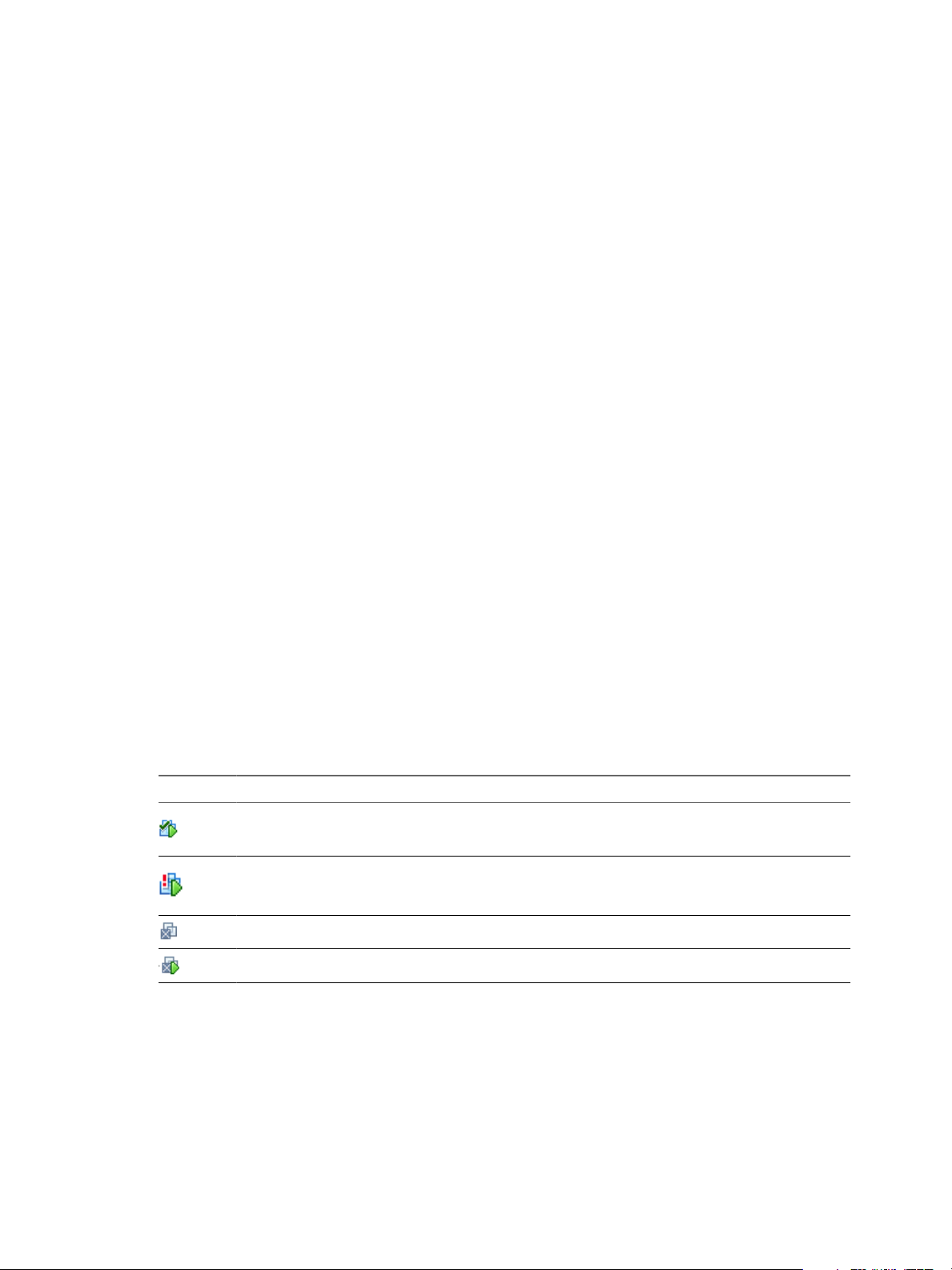
There are differences in the icons for virtual machines and vShield components between the vShield Manager
and the vSphere Client inventory panels. Custom icons are used to show the difference between vShield
components and virtual machines, and the difference between protected and unprotected virtual machines.
Table 2-1. vShield Virtual Machine Icons in the vShield Manager Inventory Panel
Icon Description
A powered on virtual machine that is protected by a vShield App.
A powered on virtual machine that is not protected by a vShield App.
A powered off virtual machine.
A protected virtual machine that is disconnected.
14 VMware, Inc.
Page 15

Chapter 2 vShield Manager User Interface Basics
Refreshing the Inventory Panel
To refresh the list of resources in the inventory panel, click . The refresh action requests the latest resource
information from the vCenter Server. By default, the vShield Manager requests resource information from the
vCenter Server every five minutes.
Searching the Inventory Panel
To search the inventory panel for a specific resource, type a string in the field atop the vShield Manager
inventory panel and click .
vShield Manager Configuration Panel
The vShield Manager configuration panel presents the settings that can be configured based on the selected
inventory resource and the output of vShield operation. Each resource offers multiple tabs, each tab presenting
information or configuration forms corresponding to the resource.
Because each resource has a different purpose, some tabs are specific to certain resources. Also, some tabs have
a second level of options.
VMware, Inc. 15
Page 16

vShield Administration Guide
16 VMware, Inc.
Page 17

Management System Settings 3
You can edit the vCenter Server, DNS and NTP server, and Lookup server that you specified during initial
login. The vShield Manager requires communication with your vCenter Server and services such as DNS and
NTP to provide details on your VMware Infrastructure inventory.
This chapter includes the following topics:
n
“Edit DNS Servers,” on page 17
n
“Edit the vShield Manager Date and Time,” on page 18
n
“Edit Lookup Service Details,” on page 18
n
“Edit vCenter Server,” on page 18
n
“Specify Syslog Server,” on page 19
n
“Download Technical Support Logs for vShield,” on page 19
n
“Add an SSL Certificate to Identify the vShield Manager Web Service,” on page 20
n
“Add a Cisco Switch to vShield Manager,” on page 21
n
“Working with Services and Service Groups,” on page 21
n
“Grouping Objects,” on page 24
Edit DNS Servers
You can change the DNS servers specified during initial login. The primary DNS server appears in the vShield
Manager user interface.
Procedure
1 Click Settings & Reports from the vShield Manager inventory panel.
2 Click the Configuration tab.
3 Ensure that you are in the General tab.
4 Click Edit next to DNS Servers.
5 Make the appropriate changes.
6 Click OK.
VMware, Inc.
17
Page 18

vShield Administration Guide
Edit the vShield Manager Date and Time
You can change the NTP server specified during initial login.
Procedure
1 Click Settings & Reports from the vShield Manager inventory panel.
2 Click the Configuration tab.
3 Ensure that you are in the General tab.
4 Click Edit next to NTP Server.
5 Make the appropriate changes.
6 Click OK.
7 Reboot the vShield Manager.
Edit Lookup Service Details
You can change the Lookup Service details specified during initial login.
Procedure
1 Click Settings & Reports from the vShield Manager inventory panel.
2 Click the Configuration tab.
3 Ensure that you are in the General tab.
4 Click Edit next to Lookup Service.
5 Make the appropriate changes.
6 Click OK.
Edit vCenter Server
You can change the vCenter Server with which you registered vShield Manager upon initial login. You should
do this only if you change the IP address of your current vCenter Server.
Procedure
1 If you are logged in to the vSphere Client, log out.
2 Log in to the vShield Manager.
3 Click Settings & Reports from the vShield Manager inventory panel.
4 Click the Configuration tab.
5 Ensure that you are in the General tab.
6 Click Edit next to vCenter Server.
7 Make the appropriate changes.
8 Click OK.
9 Log in to the vSphere Client.
10 Select an ESX host.
11 Verify that vShield appears as a tab.
18 VMware, Inc.
Page 19

What to do next
You can install and configure vShield components from the vSphere Client.
Specify Syslog Server
If you specify a syslog server, vShield Manager sends all audit logs and system events from vShield Manager
to the syslog server.
Procedure
1 Click Settings & Reports from the vShield Manager inventory panel.
2 Click the Configuration tab.
3 Ensure that you are in the General tab.
4 Click Edit next to Syslog Server.
5 Type the IP address of the syslog server.
6 (Optional) Type the port for the syslog server.
If you do not specify a port, the default UDP port for the IP address/host name of the syslog server is used.
7 Click OK.
Chapter 3 Management System Settings
Download Technical Support Logs for vShield
You can download vShield Manager audit logs and system events from a vShield component to your PC.
Audit logs refer to configuration change (such as firewall configuration change) logs while system events refer
to events that happen in the background while vShield Manager is running. For example, if vShield Manager
looses connectivity to one of the vShield App or vShield Edge appliances, a system event is logged.
Both audit logs and system events are logged with the syslog server at the Info level. System events, however,
have an internal severity which is added to the syslog message sent for that system event.
Procedure
1 Click Settings & Reports from the vShield Manager inventory panel.
2 Click the Configuration tab.
3 Click Support.
4 Under Tech Support Log Download, click Initiate next to the appropriate component.
Once initiated, the log is generated and uploaded to the vShield Manager. This might take several seconds.
5 After the log is ready, click the Download link to download the log to your PC.
The log is compressed and has the file extension .gz.
What to do next
You can open the log using a decompression utility by browsing for All Files in the directory where you saved
the file.
VMware, Inc. 19
Page 20

vShield Administration Guide
Add an SSL Certificate to Identify the vShield Manager Web Service
You can generate a certificate signing request, get it signed by a CA, and import the signed SSL certificate into
vShield Manager to authenticate the identity of the vShield Manager web service and encrypt information sent
to the vShield Manager web server. As a security best practice, you should use the generate certificate option
to generate a private key and public key, where the private key is saved to the vShield Manager.
Procedure
1 Click Settings & Reports from the vShield Manager inventory panel.
2 Click the Configuration tab.
3 Click SSL Certificate.
4 Under Generate Certificate Signing Request, complete the form by filling in the following fields:
Option Action
Common Name
Organization Unit
Organization Name
City Name
State Name
Country Code
Key Algorithm
Key Size
5 Click Generate.
Type the IP address or fully qualified domain name (FQDN) of the vShield
Manager. VMware recommends that you enter the FQDN.
Enter the department in your company that is ordering the certificate.
Enter the full legal name of your company.
Enter the full name of the city in which your company resides.
Enter the full name of the state in which your company resides.
Enter the two-digit code that represents your country. For example, the
United States is US.
Select the cryptographic algorithm to use from either DSA or RSA. VMware
recommends RSA for backward compatibility.
Select the number of bits used in the selected algorithm.
Import an SSL certificate
You can import a pre-existing or CA signed SSL certificate for use by the vShield Manager.
Procedure
1 Click Settings & Reports from the vShield Manager inventory panel.
2 Click the Configuration tab.
3 Click SSL Certificate.
4 Under Import Signed Certificate, click Browse at Certificate File to find the file.
5 Select the type of certificate file from the Certificate Type drop-down list.
If applicable, import root and intermediate certificates before importing the CA signed certificate. If there
are multiple intermediate certificates, combine them into a single file and then import the file.
6 Click Apply.
A yellow bar containing the message Successfully imported certificate is displayed at the top of the screen.
7 Click Apply Certificate.
vShield Manager is restarted to apply the certificate.
The certificate is stored in the vShield Manager.
20 VMware, Inc.
Page 21

Add a Cisco Switch to vShield Manager
You can add a Cisco switch to vShield Manager and manage its implementation.
Prerequisites
The N1K switch must have been installed on vCenter Server.
Procedure
1 Click Settings & Reports from the vShield Manager inventory panel.
2 Ensure that you are in the Configuration tab.
3 Click the Networking tab.
4 Click Add Switch Provider.
5 Type a name for the switch.
6 Type the API interface with which the switch can communicate in the following format:
https://
7 Type your N1K user name and password.
8 Click OK.
IP_of_VSM
/n1k/services/NSM.
Chapter 3 Management System Settings
The switch is added to the switch provider table.
Working with Services and Service Groups
A service is a protocol-port combination, and a service group is a group of services.
Create a Service
You can create a service and then define rules for that service.
Procedure
1 Do one of the following.
Option Description
To create a service at the global
scope
To create a service at the datacenter
scope
To create a service at the port group
scope
To create a service at the vShield
Edge scope
2 Click the Services tab.
a Log in to the vShield Manager user interface.
b Click Settings & Reports.
c Click Object Library.
a In the vSphere Client, go to Inventory > Hosts & Clusters.
b Select a datacenter from the inventory panel.
c Click the vShield tab.
a In the vSphere Client, go to Inventory > Networking.
b Select a network from the inventory panel.
c Click the vShield tab.
a In the vSphere Client, go to Inventory > Hosts & Clusters.
b Select a datacenter resource from the inventory panel.
c Click the Network Virtualization tab.
d Click the Edges tab.
e Double-click a vShield Edge instance.
f Click the Configure tab.
VMware, Inc. 21
Page 22

vShield Administration Guide
3 Select Add > Service.
4 Type a Name to identify the service.
5 Type a Description for the service.
6 Select a Protocol to which you want to add a non-standard port.
7 Type the port number(s) in Ports.
8 (Optional) When creating a service at the global or datacenter scope, select Enable inheritance to allow
visibility at underlying scopes to make this service available to underlying scopes.
9 Click OK.
The service appears in the Services table.
Create a Service Group
You can create a service group at the global, datacenter, or vShield Edge level and then define rules for that
service group.
Procedure
1 Do one of the following.
Option Description
To create a service group at the
global scope
To create a service group at the
datacenter scope
To create a service at the port group
scope
To create a service group at the
vShield Edge scope
a Log in to the vShield Manager user interface.
b Click Settings & Reports.
c Click Object Library.
a In the vSphere Client, go to Inventory > Hosts & Clusters.
b Select a datacenter resource from the inventory panel.
c Click the vShield tab.
a In the vSphere Client, go to Inventory > Networking.
b Select a network from the inventory panel.
c Click the vShield tab.
a In the vSphere Client, go to Inventory > Hosts & Clusters.
b Select a datacenter resource from the inventory panel.
c Click the Network Virtualization tab.
d Click the Edges tab.
e Double-click a vShield Edge instance.
f Click the Configure tab.
2 Click the Services tab.
3 Select Add > Service Group.
4 Type a Name to identify the service group.
5 Type a Description for the service.
6 In Members, select the services or service groups that you want to the group.
7 (Optional) When creating a service group at the global or datacenter scope, select Enable inheritance to
allow visibility at underlying scopes to make this service group available to underlying scopes.
8 Click OK.
The custom service group appears in the Services table.
22 VMware, Inc.
Page 23

Chapter 3 Management System Settings
Edit a Service or Service Group
You can edit services and service groups.
A service or service group can be edited at the scope it was defined at. For example, if a service was defined
at the global scope, it cannot be edited at the vShield Edge scope.
Procedure
1 Do one of the following.
Option Description
To edit a service at the global scope
To edit a service at the datacenter
scope
To edit a service at the port group
scope
To edit a service at the vShield Edge
scope
2 Click the Services tab.
a Log in to the vShield Manager user interface.
b Click Settings & Reports.
c Click Object Library.
a In the vSphere Client, go to Inventory > Hosts & Clusters.
b Select a datacenter resource from the inventory panel.
c Click the vShield tab.
a In the vSphere Client, go to Inventory > Networking.
b Select a network from the inventory panel.
c Click the vShield tab.
a In the vSphere Client, go to Inventory > Hosts & Clusters.
b Select a datacenter resource from the inventory panel.
c Click the Network Virtualization tab.
d Click the Edges tab.
e Double-click a vShield Edge instance.
f Click the Configure tab.
3
Select a custom service or service group and click the Edit ( ) icon.
4 Make the appropriate changes.
5 Click OK.
Delete a Service or Service Group
You can delete services or service group.
A service or service group can be deleted at the scope it was defined at. For example, if a service was defined
at the global scope, it cannot be deleted at the vShield Edge scope.
Procedure
1 Do one of the following.
Option Description
To delete a service at the global
scope
To delete a service at the datacenter
scope
a Log in to the vShield Manager user interface.
b Click Settings & Reports.
c Click Object Library.
a In the vSphere Client, go to Inventory > Hosts & Clusters.
b Select a datacenter resource from the inventory panel.
c Click the vShield tab.
VMware, Inc. 23
Page 24

vShield Administration Guide
Option Description
To delete a service at the port group
scope
To delete a service at the vShield
Edge scope
2 Click the Services tab.
3
Select a custom service or service group and click the Delete ( ) icon.
4 Click Yes.
The service or service group is deleted.
Grouping Objects
The Grouping feature enables you to create custom containers to which you can assign resources, such as
virtual machines and network adapters, for App Firewall protection. After a group is defined, you can add the
group as source or destination to a firewall rule for protection.
a In the vSphere Client, go to Inventory > Networking.
b Select a network from the inventory panel.
c Click the vShield tab.
a In the vSphere Client, go to Inventory > Hosts & Clusters.
b Select a datacenter resource from the inventory panel.
c Click the Network Virtualization tab.
d Click the Edges tab.
e Double-click a vShield Edge instance.
f Click the Configure tab.
Working with IP Address Groups
Create an IP Address Group
You can create an IP address group at the global, datacenter, or vShield Edge scope and then add this group
as the source or destination in a firewall rule. Such a rule can help protect physical machines from virtual
machines or vice versa.
Procedure
1 Do one of the following.
Option Description
To create an IP address group at the
global scope
To create an IP address group at the
datacenter scope
To create an IP address group at the
port group scope
To create an IP address group at the
vShield Edge scope
2 Click the Grouping Objects tab.
a In the vShield Manager user interface, click Object Library from the
vShield Manager inventory panel.
b Ensure that you are in the Grouping tab.
a In the vSphere Client, go to Inventory > Hosts & Clusters.
b Select a datacenter resource from the inventory panel.
c Click the vShield tab.
d From the General tab, select the Grouping tab.
a In the vSphere Client, go to Inventory > Networking.
b Select a network from the inventory panel.
c Click the vShield tab.
a In the vSphere Client, go to Inventory > Hosts & Clusters.
b Select a datacenter resource from the inventory panel.
c Click the Network Virtualization tab.
d Click the Edges tab.
e Double-click a vShield Edge instance.
f Click the Configure tab.
24 VMware, Inc.
Page 25

Chapter 3 Management System Settings
3
Click the Add (
) icon and select IP Addresses.
The Add IP Addresses window opens.
4 Type a name for the address group.
5 (Optional) Type a description for the address group.
6 Type the IP addresses to be included in the group.
7 (Optional) When creating an IP address group at the global or datacenter scope, select Enable inheritance
to allow visibility at underlying scopes to make this IP address group available to underlying scopes.
8 Click OK.
Edit an IP Address Group
An IP address group can be edited at the scope it was defined at. For example, if an IP address group was
defined at the global scope, it cannot be edited at the vShield Edge scope.
Prerequisites
Procedure
1 Do one of the following.
Option Description
To edit an IP address group at the
global scope
To edit an IP address group at the
datacenter scope
To edit an IP address group at the
port group scope
To edit an IP address group at the
vShield Edge scope
2 Click the Grouping Objects tab.
a In the vShield Manager user interface, click Object Library from the
vShield Manager inventory panel.
b Ensure that you are in the Grouping tab.
a In the vSphere Client, go to Inventory > Hosts & Clusters.
b Select a datacenter resource from the inventory panel.
c Click the vShield tab.
d From the General tab, select the Grouping tab.
a In the vSphere Client, go to Inventory > Networking.
b Select a network from the inventory panel.
c Click the vShield tab.
a In the vSphere Client, go to Inventory > Hosts & Clusters.
b Select a datacenter resource from the inventory panel.
c Click the Network Virtualization tab.
d Click the Edges tab.
e Double-click a vShield Edge instance.
f Click the Configure tab.
3
Select the group that you want to edit and click the Edit ( ) icon.
4 In the Edit IP Addresses dialog box, make the appropriate changes.
5 Click OK.
VMware, Inc. 25
Page 26

vShield Administration Guide
Delete an IP Address Group
An IP address group can be deleted at the scope it was defined at. For example, if an IP address group was
defined at the global scope, it cannot be deleted at the vShield Edge scope.
Procedure
1 Do one of the following.
Option Description
To delete an IP address group at the
global scope
To delete an IP address group at the
datacenter scope
To delete an IP address group at the
port group scope
To delete an IP address group at the
vShield Edge scope
2 Click the Grouping Objects tab.
a In the vShield Manager user interface, click Object Library from the
vShield Manager inventory panel.
b Ensure that you are in the Grouping tab.
a In the vSphere Client, go to Inventory > Hosts & Clusters.
b Select a datacenter resource from the inventory panel.
c Click the vShield tab.
d From the General tab, select the Grouping tab.
a In the vSphere Client, go to Inventory > Networking.
b Select a network from the inventory panel.
c Click the vShield tab.
a In the vSphere Client, go to Inventory > Hosts & Clusters.
b Select a datacenter resource from the inventory panel.
c Click the Network Virtualization tab.
d Click the Edges tab.
e Double-click a vShield Edge instance.
f Click the Configure tab.
3
Select the group that you want to delete and click the Delete ( ) icon.
Working with MAC Address Groups
Create a MAC Address Group
You can create a MAC address group consisting of a range of MAC addresses and then add this group as the
source or destination in a vShield App firewall rule. Such a rule can help protect physical machines from virtual
machines or vice versa.
Procedure
1 Do one of the following.
Option Description
To create a MAC address group at
the global level
To create a MAC address group at
the datacenter level
To create a MAC address at the port
group level
a In the vShield Manager user interface, click Object Library from the
vShield Manager inventory panel.
b Ensure that you are in the Grouping tab.
a In the vSphere Client, go to Inventory > Hosts & Clusters.
b Select a datacenter resource from the inventory panel.
c Click the vShield tab.
d From the General tab, select the Grouping tab.
a In the vSphere Client, go to Inventory > Networking.
b Select a network from the inventory panel.
c Click the vShield tab.
26 VMware, Inc.
Page 27

Chapter 3 Management System Settings
2
Click the Add (
) icon and select MAC Addresses.
The Add MAC Addresses window opens.
3 Type a name for the address group.
4 (Optional) Type a description for the address group.
5 Type the MAC addresses to be included in the group.
6 Select Enable inheritance to allow visibility at underlying scopes if you want the MAC address group
to propagate down to objects in the selected datacenter.
7 Click OK.
Edit a MAC Address Group
A MAC address group can be edited at the scope it was defined at. For example, if a MAC address group was
defined at the global scope, it cannot be edited at the vShield Edge scope.
Procedure
1 Do one of the following.
Option Description
To edit a MAC address group at the
global scope
To edit a MAC address group at the
datacenter scope
To edit a MAC address group at the
port group scope
To edit a MAC address group at the
vShield Edge scope
2 Click the Grouping Objects tab.
a In the vShield Manager user interface, click Object Library from the
vShield Manager inventory panel.
b Ensure that you are in the Grouping tab.
a In the vSphere Client, go to Inventory > Hosts & Clusters.
b Select a datacenter resource from the inventory panel.
c Click the vShield tab.
d From the General tab, select the Grouping tab.
a In the vSphere Client, go to Inventory > Networking.
b Select a network from the inventory panel.
c Click the vShield tab.
a In the vSphere Client, go to Inventory > Hosts & Clusters.
b Select a datacenter resource from the inventory panel.
c Click the Network Virtualization tab.
d Click the Edges tab.
e Double-click a vShield Edge instance.
f Click the Configure tab.
3
Select the group that you want to edit and click the Edit ( ) icon.
4 In the Edit MAC Addresses dialog box, make the appropriate changes.
5 Click OK.
VMware, Inc. 27
Page 28

vShield Administration Guide
Delete a MAC Address Group
A MAC address group can be deleted at the scope it was defined at. For example, if a MAC address group was
defined at the global scope, it cannot be deleted at the vShield Edge scope.
Procedure
1 Do one of the following.
Option Description
To delete a MAC address group at the
global scope
To delete a MAC address group at the
datacenter scope
To delete a MAC address group at the
port group scope
To delete a MAC address group at the
vShield Edge scope
2 Click the Grouping Objects tab.
a In the vShield Manager user interface, click Object Library from the
vShield Manager inventory panel.
b Ensure that you are in the Grouping tab.
a In the vSphere Client, go to Inventory > Hosts & Clusters.
b Select a datacenter resource from the inventory panel.
c Click the vShield tab.
d From the General tab, select the Grouping tab.
a In the vSphere Client, go to Inventory > Networking.
b Select a network from the inventory panel.
c Click the vShield tab.
a In the vSphere Client, go to Inventory > Hosts & Clusters.
b Select a datacenter resource from the inventory panel.
c Click the Network Virtualization tab.
d Click the Edges tab.
e Double-click a vShield Edge instance.
f Click the Configure tab.
3
Select the group that you want to edit and click the Delete ( ) icon.
Working with Security Groups
Create a security group
In the vSphere Client, you can add a security group at the datacenter or port group level.
The security group scope is limited to the resource level at which it is created. For example, if you create a
security group at a datacenter level, the security group is available to be added as a source or destination only
when you create a firewall rule at the datacenter level. If you create a rule for a port group within that datacenter,
the security group is not available.
Procedure
1 Do one of the following.
Option Description
To create a security group at the
datacenter level
To create a security group at the port
group level
a In the vSphere Client, go to Inventory > Hosts & Clusters.
b Select a datacenter resource from the inventory panel.
c Click the vShield tab.
d In the General tab, select the Grouping tab.
a In the vSphere Client, go to Inventory > Networking.
b Select a network from the inventory panel.
c Click the vShield tab.
d Select the Grouping tab.
28 VMware, Inc.
Page 29

Chapter 3 Management System Settings
2 Click Add and select Security Group.
The Add Security Group window opens with the selected datacenter displayed as the Scope.
3 Type a name and description for the security group.
4 Click in the field next to the Add button and select the resource you want to include in the security group.
5 In Members, select one or more resource to add to the security group.
When you add a resource to a security group, all associated resources are automatically added. For
example, when you select a virtual machine, the associated vNIC is automatically added to the security
group.
6 Click OK.
Edit a Security Group
A security group can be edited at the scope it was defined at. For example, if a security group was defined at
the datacenter scope, it cannot be edited at the port group scope.
Procedure
1 Do one of the following.
Option Description
To edit a security group at the
datacenter level
To edit a security group at the port
group level
2
Select the group that you want to edit and click the Edit ( ) icon.
a In the vSphere Client, go to Inventory > Hosts & Clusters.
b Select a datacenter resource from the inventory panel.
c Click the vShield tab.
d In the General tab, select the Grouping tab.
a In the vSphere Client, go to Inventory > Networking.
b Select a network from the inventory panel.
c Click the vShield tab.
d Select the Grouping tab.
3 In the Edit Security Group dialog box, make the appropriate changes.
4 Click OK.
Delete a Security Group
A security group can be deleted at the scope it was defined at. For example, if a security group was defined at
the datacenter scope, it cannot be deleted at the vShield port group scope.
Procedure
1 Do one of the following.
Option Description
To delete a security group at the
datacenter level
To delete a security group at the port
group level
VMware, Inc. 29
a In the vSphere Client, go to Inventory > Hosts & Clusters.
b Select a datacenter resource from the inventory panel.
c Click the vShield tab.
d In the General tab, select the Grouping tab.
a In the vSphere Client, go to Inventory > Networking.
b Select a network from the inventory panel.
c Click the vShield tab.
d Select the Grouping tab.
Page 30

vShield Administration Guide
2
Select the group that you want to delete and click the Delete ( ) icon.
30 VMware, Inc.
Page 31

User Management 4
Security operations are often managed by multiple individuals. Management of the overall system is delegated
to different personnel according to some logical categorization. However, permission to carry out tasks is
limited only to users with appropriate rights to specific resources. From the Users section, you can delegate
such resource management to users by granting applicable rights.
vShield supports Single Sign On (SSO), which enables vShield to authenticate users from other identity services
such as AD, NIS, and LDAP.
User management in the vShield Manager user interface is separate from user management in the CLI of any
vShield component.
This chapter includes the following topics:
n
“Configure Single Sign On,” on page 31
n
“Managing User Rights,” on page 32
n
“Managing the Default User Account,” on page 33
n
“Add a User Account,” on page 33
n
“Edit a User Account,” on page 35
n
“Change a User Role,” on page 35
n
“Disable or Enable a User Account,” on page 36
n
“Delete a User Account,” on page 36
Configure Single Sign On
Integrating the single sign on service with vShield improves the security of user authentication for vCenter
users and enables vShield to authenticate users from other identity services such as AD, NIS, and LDAP.
With single sign on, vShield supports authentication using authenticated SAML tokens from a trusted source
via REST API calls. vShield Manager can also acquire authentication SAML tokens for use with other VMware
solutions.
Prerequisites
n
Single sign on service must be installed on the vCenter Server.
n
NTP server must be specified so that the Single Sign On server time and vShield Manager time is in sync.
See Setup vShield Manager in the vShield Installation and Upgrade Guide.
Procedure
1 Click Settings & Reports from the vShield Manager inventory panel.
VMware, Inc.
31
Page 32

vShield Administration Guide
2 Click the Configuration tab.
3 Ensure that you are in the General tab.
4 Click Edit next to Lookup Service.
5 Type the name or IP address of the host that has the lookup service.
6 Change the port number if required.
The Lookup Service URL is displayed based on the specified host and port.
7 Type the SSO user name and password.
This enables vShield Manager to register itself with the Security Token Service server.
8 Click OK.
What to do next
Assign a role to the SSO user.
Managing User Rights
Within the vShield Manager user interface, a user’s role define the actions the user is allowed to perform on a
given resource. The role determine the user’s authorized activities on the given resource, ensuring that a user
has access only to the functions necessary to complete applicable operations. This allows domain control over
specific resources, or system-wide control if your right has no restrictions.
The following rules are enforced:
n
A user can only have one role.
n
You cannot add a role to a user, or remove an assigned role from a user. You can, however, change the
assigned role for a user.
Table 4-1. vShield Manager User Roles
Right Permissions
Enterprise Administrator vShield operations and security.
vShield Administrator vShield operations only: for example, install virtual appliances, configure port groups.
Security Administrator vShield security only: for example, define data security policies, create port groups, create
reports for vShield modules.
Auditor Read only.
The scope of a role determines what resources a particular user can view. The following scopes are available
for vShield users.
Table 4-2. vShield Manager User Scope
Scope Description
No restriction Access to entire vShield system
Limit access scope to the
selected port groups below
Access to a specified datacenter or port group
The Enterprise Administrator and vShield Administrator roles can only be assigned to vCenter users, and their
access scope is global (no restrictions).
32 VMware, Inc.
Page 33

Managing the Default User Account
The vShield Manager user interface includes a local user account, which has access rights to all resources. You
cannot edit the rights of or delete this user. The default user name is admin and the default password is
default.
Change the password for this account upon initial login to the vShield Manager. See “Edit a User Account,”
on page 35.
Add a User Account
You can either create a new user local to vShield, or assign a role to a vCenter user.
Create a New Local User
1 Click Settings & Reports from the vShield Manager inventory panel.
2 Click the Users tab.
3 Click Add.
The Assign Role window opens.
Chapter 4 User Management
4 Click Create a new user local to vShield.
5 Type an Email address.
6 Type a Login ID.
This is used for login to the vShield Manager user interface. This user name and associated password
cannot be used to access the vShield App or vShield Manager CLIs.
7 Type the user’s Full Name for identification purposes.
8 Type a Password for login.
9 Re-type the password in the Retype Password field.
10 Click Next.
11 Select the role for the user and click Next. For more information on the available roles, see “Managing
User Rights,” on page 32.
12 Select the scope for the user and click Finish.
The user account appears in the Users table.
Assign a Role to a vCenter User
When you assign a role to an SSO user, vCenter authenticates the user with the identity service configured on
the SSO server. If the SSO server is not configured or is not available, the user is authenticated either locally
or with Active Directory based on vCenter configuration.
1 Click Settings & Reports from the vShield Manager inventory panel.
2 Click the Users tab.
3 Click Add.
The Assign Role window opens.
4 Click Select vCenter user.
VMware, Inc. 33
Page 34

vShield Administration Guide
5 Type the vCenter User name for the user.
NOTE If the vCenter user is from a domain (such as a SSO user), then you must enter a fully qualified
windows domain path. This will allow the default vShield Manager user (admin) as well as the SSO default
user (admin) to login to vShield Manager. This user name is for login to the vShield Manager user interface,
and cannot be used to access the vShield App or vShield Manager CLIs.
6 Click Next.
7 Select the role for the user and click Next. For more information on the available roles, see “Managing
User Rights,” on page 32.
8 Select the scope for the user and click Finish.
The user account appears in the Users table.
Understanding Group Based Role Assignments
Organizations create user groups for proper user management. After integration with Single Sign On (SSO),
vShield Manager can get the details of groups to which a user belongs to. Instead of assigning roles to individual
users who may belong to the same group, vShield Manager assigns roles to groups. Let us walk through some
scenarios to help us understand how vShield Manager assigns roles.
Example: Scenario 1
Group option Value
Name G1
Role assigned Auditor (Read only)
Resources Global root
User option Value
Name John
Belongs to group G1
Role assigned None
John belongs to group G1 which has been assigned the auditor role. John inherits the group role and resource
permissions.
Example: Scenario 2
Group option Value
Name G1
Role assigned Auditor (Read only)
Resources Global root
Group option Value
Name G2
Role assigned Security Administrator (Read and Write)
Resources Datacenter1
34 VMware, Inc.
Page 35

Chapter 4 User Management
User option Value
Name Joseph
Belongs to group G1, G2
Role assigned None
Joseph belongs to groups G1 and G2 and inherits a combination of the rights and permissions of the Auditor
and Security Administrator roles. For example, John has the following permissions:
n
Read, write (Security Administrator role) for Datacenter1
n
Read only (Auditor) for global root
Example: Scenario 3
Group option Value
Name G1
Role assigned Enterprise Administrator
Resources Global root
User option Value
Name Bob
Belongs to group G1
Role assigned Security Administrator (Read and Write)
Resources Datacenter1
Bob has been assigned the Security Administrator role, so he does not inherit the group role permissions. Bob
has the following permissions
n
Read, write (Security Administrator role) for Datacenter1 and its child resources
n
Enterprise Administrator role on Datacenter1
Edit a User Account
You can edit a user account to change the role or scope. You cannot edit the admin account.
Procedure
1 Click Settings & Reports from the vShield Manager inventory panel.
2 Click the Users tab.
3 Select the user you want to edit.
4 Click Edit.
5 Make changes as necessary.
6 Click Finish to save your changes.
Change a User Role
You can change the role assignment for all users, except for the admin user.
Procedure
1 Click Settings & Reports from the vShield Manager inventory panel.
VMware, Inc. 35
Page 36

vShield Administration Guide
2 Click the Users tab.
3 Select the user you want to change the role for
4 Click Change Role.
5 Make changes as necessary.
6 Click Finish to save your changes.
Disable or Enable a User Account
You can disable a user account to prevent that user from logging in to the vShield Manager. You cannot disable
the admin user.
Procedure
1 Click Settings & Reports from the vShield Manager inventory panel.
2 Click the Users tab.
3 Select a user account.
4 Do one of the following.
n
Click Actions > Disable selected user(s) to disable a user account.
n
Click Actions > Enable selected user(s) to enable a user account.
Delete a User Account
You can delete any created user account. You cannot delete the admin account. Audit records for deleted users
are maintained in the database and can be referenced in an Audit Log report.
Procedure
1 Click Settings & Reports from the vShield Manager inventory panel.
2 Click the Users tab.
3 Select the user you want to delete.
4 Click Delete.
5 Click OK to confirm deletion.
If you delete a vCenter user account, only the role assignment for vShield Manager is deleted. The user
account on vCenter is not deleted.
36 VMware, Inc.
Page 37

Updating System Software 5
vShield software requires periodic updates to maintain system performance. Using the Updates tab options,
you can install and track system updates.
n
View the Current System Software on page 37
You can view the current installed versions of vShield component software or verify if an update is in
progress.
n
Upload an Update on page 37
vShield updates are available as offline updates. When an update is made available, you can download
the update to your PC, and then upload the update by using the vShield Manager user interface.
View the Current System Software
You can view the current installed versions of vShield component software or verify if an update is in progress.
Procedure
1 Click Settings & Reports from the vShield Manager inventory panel.
2 Click the Updates tab.
3 Click Update Status.
Upload an Update
vShield updates are available as offline updates. When an update is made available, you can download the
update to your PC, and then upload the update by using the vShield Manager user interface.
When the update is uploaded, the vShield Manager is updated first, after which, each vShield Zones or vShield
App instance is updated. If a reboot of either the vShield Manager or a vShield Zones or App is required, the
Update Status screen prompts you to reboot the component. In the event that both the vShield Manager and
all vShield Zones or App instances must be rebooted, you must reboot the vShield Manager first, and then
reboot each vShield Zones or App.
Procedure
1 Click Settings & Reports from the vShield Manager inventory panel.
2 Click the Updates tab.
3 Click Upload Upgrade Bundle.
4 Click Browse to locate the update.
5 After locating the file, click Upload File.
VMware, Inc.
37
Page 38

vShield Administration Guide
6 Click Update Status and then click Install.
7 Click Confirm Install to confirm update installation.
There are two tables on this screen. During installation, you can view the top table for the description,
start time, success state, and process state of the current update. View the bottom table for the update
status of each vShield App. All vShield App instances have been upgraded when the status of the last
vShield App is displayed as Finished.
8 After the vShield Manager reboots, click the Update Status tab.
9 Click Reboot Manager if prompted.
10 Click Finish Install to complete the system update.
11 Click Confirm.
38 VMware, Inc.
Page 39

Backing Up vShield Manager Data 6
You can back up and restore your vShield Manager data, which can include system configuration, events, and
audit log tables. Configuration tables are included in every backup. You can, however, exclude system and
audit log events. Backups are saved to a remote location that must be accessible by the vShield Manager.
Backups can be executed according to a schedule or on demand.
n
Back Up Your vShield Manager Data on Demand on page 39
You can back up vShield Manager data at any time by performing an on-demand backup.
n
Schedule a Backup of vShield Manager Data on page 40
You can only schedule the parameters for one type of backup at any given time. You cannot schedule a
configuration-only backup and a complete data backup to run simultaneously.
n
Restore a Backup on page 40
You can restore a backup only on a freshly deployed vShield Manager appliance.
Back Up Your vShield Manager Data on Demand
You can back up vShield Manager data at any time by performing an on-demand backup.
Procedure
VMware, Inc.
1 Click Settings & Reports from the vShield Manager inventory panel.
2 Click the Configuration tab.
3 Click Backups.
4 (Optional) Select the Exclude System Events check box if you do not want to back up system event tables.
5 (Optional) Select the Exclude Audit Logs check box if you do not want to back up audit log tables.
6 Type the Host IP Address of the system where the backup will be saved.
7 Type the Host Name of the backup system.
8 Type the User Name required to log in to the backup system.
9 Type the Password associated with the user name for the backup system.
10 In the Backup Directory field, type the absolute path where backups are to be stored.
11 Type a text string in Filename Prefix.
This text is prepended to the backup filename for easy recognition on the backup system. For example, if
you type ppdb, the resulting backup is named as ppdbHH_MM_SS_DayDDMonYYYY.
12 Enter a Pass Phrase to secure the backup file.
39
Page 40

vShield Administration Guide
13 From the Transfer Protocol drop-down menu, select either SFTP or FTP.
14 Click Backup.
Once complete, the backup appears in a table below this forms.
15 Click Save Settings to save the configuration.
Schedule a Backup of vShield Manager Data
You can only schedule the parameters for one type of backup at any given time. You cannot schedule a
configuration-only backup and a complete data backup to run simultaneously.
Procedure
1 Click Settings & Reports from the vShield Manager inventory panel.
2 Click the Configuration tab.
3 Click Backups.
4 From the Scheduled Backups drop-down menu, select On.
5 From the Backup Frequency drop-down menu, select Hourly, Daily, or Weekly.
The Day of Week, Hour of Day, and Minute drop-down menus are disabled based on the selected
frequency. For example, if you select Daily, the Day of Week drop-down menu is disabled as this field is
not applicable to a daily frequency.
6 (Optional) Select the Exclude System Events check box if you do not want to back up system event tables.
7 (Optional) Select the Exclude Audit Log check box if you do not want to back up audit log tables.
8 Type the Host IP Address of the system where the backup will be saved.
9 (Optional) Type the Host Name of the backup system.
10 Type the User Name required to login to the backup system.
11 Type the Password associated with the user name for the backup system.
12 In the Backup Directory field, type the absolute path where backups will be stored.
13 Type a text string in Filename Prefix.
This text is prepended to each backup filename for easy recognition on the backup system. For example,
if you type ppdb, the resulting backup is named as ppdbHH_MM_SS_DayDDMonYYYY.
14 From the Transfer Protocol drop-down menu, select either SFTP or FTP, based on what the destination
supports.
15 Click Save Settings.
Restore a Backup
You can restore a backup only on a freshly deployed vShield Manager appliance.
To restore an available backup, the Host IP Address, User Name, Password, and Backup Directory fields in
the Backups screen must have values that identify the location of the backup to be restored. If the backup file
contains system event and audit log data, that data is also restored.
IMPORTANT Back up your current data before restoring a backup file.
Procedure
1 Click Settings & Reports from the vShield Manager inventory panel.
40 VMware, Inc.
Page 41

Chapter 6 Backing Up vShield Manager Data
2 Click the Configuration tab.
3 Click Backups.
4 Click View Backups to view all available backups saved to the backup server.
5 Select the check box for the backup to restore.
6 Click Restore.
7 Click OK to confirm.
VMware, Inc. 41
Page 42

vShield Administration Guide
42 VMware, Inc.
Page 43

System Events and Audit Logs 7
System events are events that are related to vShield operation. They are raised to detail every operational event,
such as a vShield App reboot or a break in communication between a vShield App and the vShield Manager.
Events might relate to basic operation (Informational) or to a critical error (Critical).
This chapter includes the following topics:
n
“View the System Event Report,” on page 43
n
“vShield Manager Virtual Appliance Events,” on page 43
n
“vShield App Events,” on page 44
n
“About the Syslog Format,” on page 45
n
“View the Audit Log,” on page 45
View the System Event Report
The vShield Manager aggregates system events into a report.
Procedure
1 Click Settings & Reports from the vShield Manager inventory panel.
2 Click the System Events tab.
3
To sort events, click
or next to the appropriate column header.
vShield Manager Virtual Appliance Events
The following events are specific to the vShield Manager virtual appliance.
Table 7-1. vShield Manager Virtual Appliance Events
Power Off Power On Interface Down Interface Up
Local CLI Run show log follow
command.
GUI NA NA NA NA
VMware, Inc. 43
Run show log follow
command.
Run show log follow
command.
Run show log follow
command.
Page 44

vShield Administration Guide
Table 7-2. vShield Manager Virtual Appliance Events
CPU Memory Storage
Local CLI Run show process monitor
command.
GUI NA NA NA
vShield App Events
The following events are specific to vShield App virtual appliances.
Table 7-3. vShield App Events
Power Off Power On Interface Down Interface Up
Local CLI Run show log
follow command.
Syslog NA See “About the
GUI “Heartbeat failure”
event in System
Event log. See
“View the System
Event Report,” on
page 43.
Run show system memory
command.
Run show log
follow
command.
Syslog Format,”
on page 45.
See “Viewing the
Current System
Status of a vShield
App,” on
page 152.
Run show log follow
command.
e1000: mgmt:
e1000_watchdog_task:
NIC Link is Up/Down 100
Mbps Full Duplex. For
scripting on the syslog server,
search for NIC Link is.
See “Viewing the Current
System Status of a vShield
App,” on page 152.
Run show filesystem command.
Run show log follow
command.
e1000: mgmt:
e1000_watchdog_task: NIC
Link is Up/Down 100 Mbps
Full Duplex. For scripting on
the syslog server, search for
NIC Link is.
See “Viewing the Current
System Status of a vShield
App,” on page 152.
Table 7-4. vShield AppAppliance Status Events
Session reset due to DoS,
CPU Memory Storage
Local CLI Run show process
monitor command.
Syslog NA NA See “About the Syslog
GUI 1 From the vShield
Manager
inventory panel,
select the host
which has vShield
App installed.
2 In Service Virtual
Machines, click
next to the
vShield App
virtual machine.
Run show system
memory command.
1 From the vShield
Manager
inventory panel,
select the host
which has vShield
App installed.
2 In Service Virtual
Machines, click
next to the
vShield App
virtual machine.
Run show
filesystem
command.
1 From the vShield
Manager
inventory panel,
select the host
which has vShield
App installed.
2 In Service Virtual
Machines, click
next to the
vShield App
virtual machine.
Inactivity, or Data Timeouts
Run show log follow
command.
Format,” on page 45.
1 From the vShield Manager
inventory panel, select the
host which has vShield App
installed.
2 In Service Virtual
Machines, click
the vShield App virtual
machine.
next to
44 VMware, Inc.
Page 45

About the Syslog Format
Is this the same for SPOCK?
The system event message logged in the syslog has the following structure.
syslog header (timestamp + hostname + sysmgr/)
Timestamp (from the service)
Name/value pairs
Name and value separated by delimiter '::' (double colons)
Each name/value pair separated by delimiter ';;' (double semi-colons)
The fields and types of the system event contain the following information.
Event ID :: 32 bit unsigned integer
Timestamp :: 32 bit unsigned integer
Application Name :: string
Application Submodule :: string
Application Profile :: string
Event Code :: integer (possible values: 10007 10016 10043 20019)
Severity :: string (possible values: INFORMATION LOW MEDIUM HIGH CRITICAL)
Message ::
Chapter 7 System Events and Audit Logs
View the Audit Log
The Audit Logs tab provides a view into the actions performed by all vShield Manager users. The vShield
Manager retains audit log data for one year, after which time the data is discarded.
Procedure
1 Click Settings & Reports from the vShield Manager inventory panel.
2 Click the Audit Logs tab.
3 To view details of an audit log, click the text in the Operation column. When details are available for an
audit log, the text in the Operation column for that log is clickable.
4 In the Audit Log Change Details, select Changed Rows to display only properties whose values have
changed after the operation was performed.
VMware, Inc. 45
Page 46

vShield Administration Guide
46 VMware, Inc.
Page 47

VXLAN Virtual Wires Management 8
VM VM VM
Virtual Network
Virtual Wire
VM VM
VXLAN
Distributed
switches
In large cloud deployments, applications within virtual networks may need to be logically isolated. For
example, a three-tier application can have multiple virtual machines requiring logically isolated networks
between the virtual machines. Traditional network isolation techniques such as VLAN (4096 LAN segments
through a 12-bit VLAN identifier) may not provide enough segments for such deployments. In addition, VLAN
based networks are bound to the physical fabric and their mobility is restricted.
The vShield VXLAN virtual wire is a scalable flat Layer 2 network segment. This feature allows you provides
network agility by allowing you to deploy an application on any available cluster and transport virtual
machines across a broader diameter. The underlying technology, referred to as Virtual eXtensible LAN (or
VXLAN), defines a 24-bit LAN segment identifier to provide segmentation at cloud-deployment scale. VXLAN
virtual wires enable you to grow your cloud deployments with repeatable pods in different subnets. Cross
cluster placement of virtual machines helps you to fully utilize your network resources without any physical
re-wiring. VXLAN virtual wires thus provide application level isolation.
Figure 8-1. VXLAN Virtual wire overview
VMware, Inc.
You must be a Security Administrator in order to create VXLAN virtual wires.
This chapter includes the following topics:
n
“Preparing your Network for VXLAN Virtual Wires,” on page 48
n
“Create a VXLAN Virtual Wire,” on page 49
n
“Connect Virtual Machines to a VXLAN Virtual Wire,” on page 51
n
“Test VXLAN Virtual Wire Connectivity,” on page 52
47
Page 48

vShield Administration Guide
n
“Viewing Flow Monitoring Data for a VXLAN Virtual Wire,” on page 53
n
“Working with Firewall Rules for VXLAN Virtual Wires,” on page 53
n
“Prevent Spoofing on a VXLAN Virtual Wire,” on page 54
n
“Editing Network Scopes,” on page 54
n
“Edit a VXLAN Virtual Wire,” on page 55
n
“Sample Scenario for Creating VXLAN Virtual Wires,” on page 56
Preparing your Network for VXLAN Virtual Wires
You must prepare your network for VXLAN virtual wires by specifying a transport VLAN and enabling IP
multicast. These preparation steps need to be done only once - you can then create multiple VXLAN virtual
wires.
Prerequisites
Go through the following checklist to prepare for creating VXLAN virtual wires in your network:
n
Ensure that you have the following software versions
n
VMware vCenter Server 5.1 or later
n
VMware ESX 5.1 or later on each server
n
vSphere Distributed Switch 5.1 or later
n
Physical infrastructure MTU must be at least 50 bytes more than the MTU of the virtual machine vNIC
n
Get multicast address range from your network administrator and segment ID pool
n
Set Managed IP address for each vCenter server in the vCenter Server Runtime Settings. For more
information, see vCenter Server and Host Management.
n
Verify that DHCP is available on VXLAN transport VLANs
n
For Link Aggregation Control Protocol (LACP), 5- tuple hash distribution must be enabled
Associating Clusters with Distributed Switches
You must map each cluster that is to participate in a virtualized network to a vDS. When you map a cluster to
a switch, each host in that cluster is enabled for VXLAN virtual wires.
Prerequisites
VMware recommends that you use a consistent switch type (vendor etc.) and version across a given network
scope. Inconsistent switch types can lead to undefined behavior in your VXLAN virtual wire.
Procedure
1 In the vSphere Client, select Inventory > Hosts & Clusters.
2 Select a datacenter resource from the inventory panel.
3 Click the Network Virtualization tab.
4 Ensure that you are in the Preparation tab.
5 In Connectivity, click Edit.
The Prepare Infrastructure for VXLAN networking dialog box appears.
6 Select the clusters that are to participate in the virtual network.
48 VMware, Inc.
Page 49

Chapter 8 VXLAN Virtual Wires Management
7 For each selected cluster, type the VLAN used for VXLAN transport.
For information on retrieving the VLAN ID of the VXLAN VLAN, see the vSphere Networking
documentation.
8 Click Next.
9 In Specify Transport Attributes, type the Maximum Transmission Units (MTU) for each virtual distributed
switch. MTU is the maximum amount of data that can be transmitted in one packet before it is divided
into smaller packets. VXLAN traffic frames are slightly larger in size because of the encapsulation, so the
MTU for each switch must be set to 1550 or higher.
10 Click Finish.
You have now pooled your compute resources and are ready to create VXLAN virtual wires on demand.
Assign Segment ID Pool and Multicast Address Range to vShield Manager
You must specify a segment ID pool to isolate your network traffic, and a multicast address range to help in
spreading traffic across your network to avoid overloading a single multicast address.
Procedure
1 In the vSphere Client, select Inventory > Hosts & Clusters.
2 Select a datacenter resource from the inventory panel.
3 Click the Network Virtualization tab.
4 Ensure that you are in the Preparation tab.
5 Click the Segment ID tab.
6 Click Edit.
The Edit Settings dialog box opens.
7 Type a range for segment IDs. For example, 5000-5200.
8 Type an address range. For example, 224.1.1.50-224.1.1.60.
9 Click OK.
Create a VXLAN Virtual Wire
Prerequisites
Your network is prepared for VXLAN virtual wires.
Add a Network Scope
A network scope is the compute diameter spanned by your virtualized network and may contain multiple
VXLAN virtual wires.
Procedure
1 In the vSphere Client, select Inventory > Hosts & Clusters.
2 Select a datacenter resource from the inventory panel.
3 Click the Network Virtualization tab.
4 Click the Network Scopes tab.
VMware, Inc. 49
Page 50

vShield Administration Guide
5
Click the Add (
The Add Network Scope dialog box opens.
6 Type a name for the network scope.
7 Type a description for the network scope.
8 Select the clusters you want to add to the network scope.
9 Click OK.
) icon.
Add a VXLAN Virtual Wire
After you prepare the VXLAN fabric, you can add a VXLAN virtual wire. A VXLAN virtual wire provides the
necessary networking abstraction so that the vNICs of a virtual machine always use a VXLAN virtual wire for
connectivity to outside world.
Prerequisites
1 Your network is prepared for VXLAN virtual wires.
2 You have added a network scope.
Procedure
1 In the vSphere Client, select Inventory > Hosts & Clusters.
2 Select a datacenter resource from the inventory panel.
3 Click the Network Virtualization tab.
4 Click the Networks tab.
5 Click the Add icon.
6 Type a name for the VXLAN virtual wire.
7 Type a description for the VXLAN virtual wire.
8 Select the network scope in which you want to create the virtualized network. The Scope Details panel
displays the clusters that are part of the selected network scope and the services available to be deployed
on the scope.
9 Click OK.
What to do next
Click on the VXLAN virtual wire in the Name column to view the virtual wire details.
Connect a VXLAN Virtual Wire to a vShield Edge
Connecting a VXLAN virtual wire to a vShield Edge interface to isolates the VXLAN virtual wire and provides
network edge security.
Procedure
1 In the vSphere Client, select Inventory > Hosts & Clusters.
2 Select a datacenter resource from the inventory panel.
3 Click the Network Virtualization tab.
4 Click the Networks tab.
5 Select the VXLAN virtual wire that you want to connect a vShield Edge.
50 VMware, Inc.
Page 51

Chapter 8 VXLAN Virtual Wires Management
6
Click the More Actions ( ) icon and select Connect to Edge.
7 Select the vShield Edge to which you want to connect the VXLAN virtual wire.
8 Click Select.
9 In the Redirect to Selected Edge dialog box, click Continue.
10 In the Edit Edge Interface dialog box, type a name for the vShield Edge interface.
11 Select Internal or Uplink to indicate whether this is an internal or uplink interface.
A VXLAN virtual wire is typically connected to an internal interface.
12 The VXLAN virtual wire name is displayed in the Connected To area.
13 Select the connectivity status for the interface.
14 If the vShield Edge to which you are connecting the VXLAN virtual wire to has Manual HA Configuration
selected, specify two management IP addresses in CIDR format.
15 Edit the default MTU if required.
16 Click OK.
Deploy Services on a VXLAN Virtual Wire
You can deploy third party services on a VXLAN virtual wire.
Prerequisites
For information on adding services to vShield Manager, see “Inserting a Network Services,” on page 145.
Procedure
1 In the vSphere Client, select Inventory > Hosts & Clusters.
2 Select a datacenter resource from the inventory panel.
3 Click the Network Virtualization tab.
4 Click the Networks tab.
5 In the Name column, click the virtual wire that you want to deploy services on.
6 In the Available Services panel, click Enable Services.
7 In the Apply Service Profile to this Network dialog box, select the service and service profile that you want
to apply.
8 Click Apply.
Connect Virtual Machines to a VXLAN Virtual Wire
You can connect virtual machines to a VXLAN virtual wire. This makes it easy to identify the port groups that
belong to a virtual wire in your vCenter inventory.
Procedure
1 In the vSphere Client, select Inventory > Hosts & Clusters.
2 Select a datacenter resource from the inventory panel.
3 Click the Network Virtualization tab.
4 Click the Networks tab.
5 In the Name column, click the VXLAN virtual wire that you want to edit.
VMware, Inc. 51
Page 52

vShield Administration Guide
6 Click the Virtual Machines tab.
7
Click the Add (
8 In the Connect VNics to this Network dialog box, type the name of the virtual machine in the Search field
and click .
All VNics for the virtual machine are displayed.
9 Select the VNics that you want to connect.
10 Click Next.
11 Review the VNics you selected.
12 Click Finish.
) icon.
Test VXLAN Virtual Wire Connectivity
You can do a ping or broadcast test on a VXLAN virtual wire to check its connectivity and physical
infrastructure plumbing for VXLAN.
Perform Ping Test
You can ping a destination host from a source host before sending a unicast packet.
1 In the vSphere Client, select Inventory > Hosts & Clusters.
2 Select a datacenter resource from the inventory panel.
3 Click the Network Virtualization tab.
4 Click the Networks tab.
5 In the Name column, click the VXLAN virtual wire that you want to test.
6 Click the Hosts tab.
7 Select a host.
8
Click the More Actions ( ) icon and select Test Connectivity.
The Test Connectivity Between Hosts in the Network dialog box opens. The host you selected in step 7
appears in the Source host field. Select Browse to select a different source host.
9 Select the size of the test packet.
VXLAN standard size is 1550 bytes (should match the physical infrastructure MTU) without
fragmentation. This allows vShield to check connectivity and verify that the infrastructure is prepared for
VXLAN traffic.
Minimum packet size allows fragmentation. Hence, vShield can check only connectivity but not whether
the infrastructure is ready for the larger frame size.
10 In the Destination panel, click Browse Hosts.
11 In the Select Host dialog box, select the destination host.
12 Click Select.
13 Click Start Test.
The host-to-host ping test results are displayed.
52 VMware, Inc.
Page 53

Chapter 8 VXLAN Virtual Wires Management
Perform Broadcast Test
You can perform a broadcast test to resolve MAC addresses. A single host sends a broadcast message to all
other devices on the same network segment.
1 In the vSphere Client, select Inventory > Hosts & Clusters.
2 Select a datacenter resource from the inventory panel.
3 Click the Network Virtualization tab.
4 Click the Networks tab.
5 In the Name column, click the virtual wire that you want to test.
6 Click the Hosts tab.
7 Select a host.
8
Click the More Actions (
9 In the Test Connectivity Between Hosts in the Network dialog box, click Broadcast
The host you selected in step 7 appears in the Source host field. Select Browse to select a different source
host.
10 Select the size of the test packet.
VXLAN standard size is 1550 bytes (should match the physical infrastructure MTU) without
fragmentation. This allows vShield to check connectivity and verify that the infrastructure is prepared for
VXLAN traffic.
Minimum packet size allows fragmentation. Hence, vShield can check infrastructure connectivity but not
whether the infrastructure is ready for the larger frame size.
11 Click Start Test.
The broadcast test results are displayed.
) icon and select Test Connectivity.
Viewing Flow Monitoring Data for a VXLAN Virtual Wire
Flow Monitoring is a traffic analysis tool that provides a detailed view of the traffic on your VXLAN virtual
wire that passed through a vShield App. The Flow Monitoring output defines which machines are exchanging
data and over which application. This data includes the number of sessions, packets, and bytes transmitted
per session. Session details include sources, destinations, direction of sessions, applications, and ports being
used. Session details can be used to create firewall allow or block rules.
You can use Flow Monitoring as a forensic tool to detect rogue services and examine outbound sessions. Flow
monitoring data is available for two weeks.
Flow monitoring data is available only if you have vShield App installed on the hosts in the VXLAN virtual
wire clusters.
For more information, see Chapter 12, “vShield App Flow Monitoring,” on page 155.
Working with Firewall Rules for VXLAN Virtual Wires
vShield App provides firewall protection to your VXLAN virtual wires through access policy enforcement.
For more information, see Chapter 13, “vShield App Firewall Management,” on page 161.
VMware, Inc. 53
Page 54

vShield Administration Guide
Prevent Spoofing on a VXLAN Virtual Wire
After synchronizing with the vCenter Server, vShield Manager collects the IP addresses of all vCenter guest
virtual machines from VMware Tools on each virtual machine. vShield does not trust all IP address provided
by VMware Tools on a virtual machine. If a virtual machine has been compromised, the IP address can be
spoofed and malicious transmissions can bypass firewall policies.
SpoofGuard allows you to authorize the IP addresses reported by VMware Tools, and alter them if necessary
to prevent spoofing. SpoofGuard inherently trusts the MAC addresses of virtual machines collected from the
VMX files and vSphere SDK. Operating separately from the App Firewall rules, you can use SpoofGuard to
block traffic determined to be spoofed.
For more information, see “Using SpoofGuard,” on page 168.
Editing Network Scopes
You can edit, expand, or contract a network scope.
View and Edit a Network Scope
You can view the VXLAN virtual wires in a selected network scope, the clusters in, and the services available
for that network scope.
Procedure
1 In the vSphere Client, select Inventory > Hosts & Clusters.
2 Select a datacenter resource from the inventory panel.
3 Click the Network Virtualization tab.
4 Click the Network Scope tab.
All network scopes for the selected datacenter are displayed.
5 In the Name column, click on a network scope.
The Summary tab displays the following information. Click Edit in the appropriate section to make
changes.
n
The Properties section displays the name and description of the network scope and the number of
VXLAN virtual wires based on this network scope.
n
The Network Scope section displays the clusters in the network scope and whether they are ready
for virtualized networking (i.e. whether the clusters have been mapped to a vDS).
n
The Available Services section displays the services available for the network scope.
Expand a Network Scope
You can add clusters to a network scope. This will stretch all existing VXLAN virtual wires to become available
on the newly added clusters.
Prerequisites
The clusters you add to a network scope must be prepared. See “Preparing your Network for VXLAN Virtual
Wires,” on page 48.
Procedure
1 In the vSphere Client, select Inventory > Hosts & Clusters.
54 VMware, Inc.
Page 55

Chapter 8 VXLAN Virtual Wires Management
2 Select a datacenter resource from the inventory panel.
3 Click the Network Virtualization tab.
4 Click the Network Scope tab.
All network scope for the selected datacenter are displayed.
5 In the Name column, click a network scope.
6 In Scope Details, click Expand.
The Add Clusters to a Network Scope (Expand) dialog box opens.
7 Select the clusters you want to add to the network scope.
8 Click OK.
Contract a Network Scope
You can remove clusters from a network scope. Existing VXLAN virtual wires may be shrunk to accommodate
the contracted scope.
Procedure
1 In the vSphere Client, select Inventory > Hosts & Clusters.
2 Select a datacenter resource from the inventory panel.
3 Click the Network Virtualization tab.
4 Click the Network Scope tab.
All network scopes for the selected datacenter are displayed.
5 In the Name column, click on a network scope.
6 In Scope Details, click Contract.
The Remove Clusters from a Network Scope (Contract) dialog box opens.
7 Select the clusters you want to remove from the network scope.
8 Click OK.
Edit a VXLAN Virtual Wire
You can edit the name and description of a VXLAN virtual wire.
Procedure
1 In the vSphere Client, select Inventory > Hosts & Clusters.
2 Select a datacenter resource from the inventory panel.
3 Click the Network Virtualization tab.
4 Click the Networks tab.
5 In the Name column, click the VXLAN virtual wire to edit.
6 Click Edit.
7 Make the desired changes.
8 Click OK.
VMware, Inc. 55
Page 56

Engineering
PG
Finance
PG
Physical Switch
Cluster 1
Engineering: VLAN10:10.10.1.0/24
Finance: VLAN20:10.20.1.0/24
Marketing: VLAN30:10.30.1.0/24
vDS1
VM VM VM
Physical Switch
vDS2
VM
Marketing
PG
Cluster 2
VM VM VM
vShield Administration Guide
Sample Scenario for Creating VXLAN Virtual Wires
This scenario presents a situation where company ACME Enterprise has several ESX hosts on two clusters in
a datacenter, ACME_Datacenter. The Engineering (on port group PG-Engineering) and Finance departments
(on port group PG-Finance) are on Cluster1. The Marketing department (PG-Marketing) is on Cluster2. Both
clusters are managed by a single vCenter Server 5.1.
Figure 8-2. ACME Enterprise network before implementing VXLAN virtual wires
ACME is running out of compute space on Cluster1 while Cluster2 is under-utilized. The ACME network
supervisor asks John Admin (ACME's virtualization administrator) to figure out a way to extend the
Engineering department to Cluster2 in a way that virtual machines belonging to Engineering on both clusters
can communicate with each other. This would enable ACME to utilize the compute capacity of both clusters
by stretching ACME's L2 layer.
If John Admin were to do this the traditional way, he would need to connect the separate VLANs in a special
way so that the two clusters can be in the same L2 domain. This might require ACME to buy a new physical
device to separate traffic, and lead to issues such as VLAN sprawl, network loops, and administration and
management overhead.
John Admin remembers seeing a VXLAN virtual wire demo at VMworld 2011, and decides to evaluate the
vShield 5.1 release. He concludes that building a VXLAN virtual wire across dvSwitch1 and dvSwitch2 will
allow him to stretch ACME's L2 layer.
56 VMware, Inc.
Page 57

Figure 8-3. ACME Enterprise implements a VXLAN virtual wire
Engineering
PG
FFiinnaannccee
PPGG
Physical Switch
Cluster 1
vDS1
VM VM VM
Physical Switch
vDS2
VM
MMaarrkkeettiinngg
PPGG
Cluster 2
Virtual wire stretches across multiple VLANs/subnets
VM VM VM
Engineering: VXLAN5000:10.10.1.0/24
Finance: VXLAN5001:10.20.1.0/24
Marketing: VXLAN5002:10.30.1.0/24
Engineering
PG
VM VM VM
VM VM
vMotion range vMotion range
Engineering
PG
FFiinnaannccee
PPGG
vDS1
VM VM VM
vDS2
VM
MMaarrkkeettiinngg
PPGG
VM VM VM
Engineering: VXLAN5000:10.10.1.0/24
Finance: VXLAN5001:10.20.1.0/24
Marketing: VXLAN5002:10.30.1.0/24
Engineering
PG
VM VM VM
VM VM
Chapter 8 VXLAN Virtual Wires Management
Once John Admin builds a VXLAN virtual wire across the two clusters, he can vMotion virtual machines across
the VDSes.
Figure 8-4. vMotion on a VXLAN virtual wire
VMware, Inc. 57
Let us walk through the steps that John Admin follows to build a VXLAN virtual wire at ACME Enterprise.
Page 58

vShield Administration Guide
John Admin Associates Cluster with Distributed Switches
John Admin must map each cluster that is to participate in a virtualized network to a vDS. When he maps a
cluster to a switch, each host in that cluster is enabled for VXLAN virtual wires.
Prerequisites
1 John Admin gets a segment ID pool (4097 - 5010) from ACME's vShield manager admin and a multi cast
address range (224.0.0.0 to 239.255.255.255 ) from ACME's network administrator.
2 John Admin sets the Managed IP address for the vCenter Server.
a Select Administration > vCenter Server Settings > Runtime Settings.
b In vCenter Server Managed IP, type 10.115.198.165.
c Click OK.
3 John Admin ensures that a DHCP server is available on VXLAN transport VLANs.
4 John Admin verifies that both dvSwitch1 and dvSwitch2 are the same version and from the same vendor.
Procedure
1 In the vSphere Client, select Inventory > Hosts & Clusters.
2 Select ACME_Datacenter from the inventory panel.
3 Click the Network Virtualization tab.
4 Ensure that you are in the Preparation tab.
5 In Connectivity, click Edit.
6 In the Prepare Infrastructure for VXLAN networking dialog box, select Cluster1 to participate in the
VXLAN virtual wire.
7 Type 10 for dvSwitch1 to use as the ACME VXLAN transport VLAN.
8 Click Next.
9 In Specify Transport Attributes, leave 1600 as the Maximum Transmission Units (MTU) for dvSwitch1.
MTU is the maximum amount of data that can be transmitted in one packet before it is divided into smaller
packets. John Admin knows that VXLAN virtual wire traffic frames are slightly larger in size because of
the encapsulation, so the MTU for each switch must be set to 1550 or higher.
10 Repeat steps 5 through step 7 and select Cluster2 to participate in the VXLAN virtual wire.
11 In Specify Transport Attributes, type 20 for dvSwitch2.
12 Leave 1600 as the Maximum Transmission Units (MTU) for dvSwitch2.
13 Click Finish.
After John admin maps Cluster1 and Cluster2 to the appropriate switch, the hosts on those clusters are prepared
for VXLAN virtual wires:
1 A VXLAN kernel module and vmknic is added to each host in Cluster1 and Cluster2.
2 A special dvPortGroup is created on the vDS associated with the VXLAN virtual wire and the vmknic is
connected to it.
58 VMware, Inc.
Page 59

Chapter 8 VXLAN Virtual Wires Management
John Admin Assigns Segment ID Pool and Multicast Address Range to vShield Manager
John Admin must specify the segment ID pool he received to isolate Company ABC's network traffic and the
multicast address range to help in spreading traffic across the network to avoid overloading a single multicast
address.
Procedure
1 In the vSphere Client, select Inventory > Hosts & Clusters.
2 Select ABC_Datacenter from the inventory panel.
3 Click the Network Virtualization tab.
4 Ensure that you are in the Preparation tab.
5 Click the Segment ID tab.
6 Click Edit.
The Edit Settings dialog box opens.
7 In Segment ID pool, type 500-510.
8 In Multicast addresses, type 224.1.1.50-224.1.1.60.
9 Click OK.
John Admin Adds a Network Scope
The physical network backing a VXLAN virtual wire is called a network scope. A network scope is the compute
diameter spanned by a virtualized network.
Procedure
1 In the vSphere Client, select Inventory > Hosts & Clusters.
2 Select ABC_Datacenter from the inventory panel.
3 Click the Network Virtualization tab.
4 Click the Network Scopes tab.
5
Click the Add ( ) icon.
The Add Network Scope dialog box opens.
6 In Name, type ACME Scope.
7 In Description, type Scope containing ACME's clusters.
8 Select Cluster1 and Cluster2 to add to the network scope.
9 Click OK.
John Admin Adds a VXLAN Virtual Wire
After John Admin prepares the VXLAN virtual wire fabric, he can add a VXLAN virtual wire. A VXLAN virtual
wire provides the necessary networking abstraction so that the vNICs of a VXLAN virtual wire always use a
VXLAN virtual wire for connectivity to outside world.
Prerequisites
1 ACME's network is prepared for VXLAN virtual wires.
VMware, Inc. 59
Page 60

vShield Administration Guide
2 John Admin has added a network scope.
Procedure
1 In the vSphere Client, select Inventory > Hosts & Clusters.
2 Select ABC_Datacenter from the inventory panel.
3 Click the Network Virtualization tab.
4 Click the Networks tab.
5 Click the Add icon.
6 In Name, type ACME virtual wire.
7 In Description, type Virtual wire for extending ACME Engineering network to Cluster2.
8 In Network Scope, select ACME Scope.
9 Review the Scope Details.
10 Click OK.
vShield creates a VXLAN virtual wire providing L2 connectivity (via VXLANs) between dvSwitch1 and
dvSwitch2.
What to do next
John Admin can now connect ACME's production virtual machines to the VXLAN virtual wire, and connect
the VXLAN virtual wire to a vShield Edge.
60 VMware, Inc.
Page 61

vShield Edge Management 9
vShield Edge provides network edge security and gateway services to isolate the virtual machines in a port
group, vDS port group, or Cisco® Nexus 1000V. The vShield Edge connects isolated, stub networks to shared
(uplink) networks by providing common gateway services such as DHCP, VPN, NAT, and Load Balancing.
Common deployments of vShield Edge include in the DMZ, VPN Extranets, and multi-tenant Cloud
environments where the vShield Edge provides perimeter security for Virtual Datacenters (VDCs).
This chapter includes the following topics:
n
“View the Status of a vShield Edge,” on page 62
n
“Configure vShield Edge Settings,” on page 62
n
“Managing Appliances,” on page 62
n
“Working with Interfaces,” on page 64
n
“Working with Certificates,” on page 67
n
“Managing the vShield Edge Firewall,” on page 70
n
“Managing NAT Rules,” on page 75
n
“Working with Static Routes,” on page 77
VMware, Inc.
n
“Managing DHCP Service,” on page 78
n
“Managing VPN Services,” on page 80
n
“Managing Load Balancer Service,” on page 135
n
“About High Availability,” on page 140
n
“Configure DNS Servers,” on page 141
n
“Configure Remote Syslog Servers,” on page 142
n
“Change CLI Credentials,” on page 142
n
“Upgrade vShield Edge to Large or X-Large,” on page 142
n
“Download Tech Support Logs for vShield Edge,” on page 143
n
“Synchronize vShield Edge with vShield Manager,” on page 143
n
“Redeploy vShield Edge,” on page 144
61
Page 62

vShield Administration Guide
View the Status of a vShield Edge
The status page displays graphs for the traffic flowing through the interfaces of the selected vShield Edge and
connection statistics for the firewall and load balancer services.
Procedure
1 In the vSphere Client, select Inventory > Hosts & Clusters.
2 Select a datacenter resource from the inventory panel.
3 Click the Network Virtualization tab.
4 Click the Edges link.
5 Double-click the vShield Edge instance to check the status for.
6 Click the Status tab.
Configure vShield Edge Settings
The Settings page displays detailed information about the selected vShield Edge.
Procedure
1 In the vSphere Client, select Inventory > Hosts and Clusters.
2 Select a datacenter resource from the inventory panel.
3 Click the Network Virtualization tab.
4 Click the Edges link.
5 Click the Configure tab.
6 Click the Settings link.
vShield Edge details, services configured for the vShield Edge, and the HA and DNS configurations are
displayed.
What to do next
Change the desired configuration by clicking Change.
Managing Appliances
You can add, edit, or delete appliances. A vShield Edge instance remains offline till at least one appliance has
been added to it.
Add an Appliance
You must add at least one appliance to vShield Edge before deploying it.
Procedure
1 In the vSphere Client, select Inventory > Hosts and Clusters.
2 Select a datacenter resource from the inventory panel.
3 Click the Network Virtualization tab.
4 Click the Edges link.
5 Click the Configure tab.
62 VMware, Inc.
Page 63

6 Click the Settings link.
Chapter 9 vShield Edge Management
7
In Edge Appliances, click the Add (
8 In the Add Edge Appliance dialog box, select the cluster or resource pool and datastore for the appliance.
9 (Optional) Select the host on which the appliance is to be added.
10 (Optional) Select the vCenter folder within which the appliance is to be added.
11 Click Add.
) icon.
Change an Appliance
You can change a vShield Edge appliance.
Procedure
1 In the vSphere Client, select Inventory > Hosts and Clusters.
2 Select a datacenter resource from the inventory panel.
3 Click the Network Virtualization tab.
4 Click the Edges link.
5 Click the Configure tab.
6 Click the Settings link.
7 In Edge Appliances, select the appliance to change.
8
Click the Edit (
) icon.
9 In the Edit Edge Appliance dialog box, make the appropriate changes.
10 Click Save.
Delete an Appliance
You can delete a vShield Edge appliance.
Procedure
1 In the vSphere Client, select Inventory > Hosts and Clusters.
2 Select a datacenter resource from the inventory panel.
3 Click the Network Virtualization tab.
4 Click the Edges link.
5 Click the Configure tab.
6 Click the Settings link.
7 In Edge Appliances, select the appliance to delete.
8
Click the Delete ( ) icon.
VMware, Inc. 63
Page 64

vShield Administration Guide
Working with Interfaces
You install a vShield Edge on a datacenter and can add up to ten internal or uplink interfaces. A vShield Edge
must have at least one internal interface before it can be deployed.
Add an Interface
You can add up to ten internal and uplink interfaces to a vShield Edge instance. You must add at least one
internal interface for HA to work.
Procedure
1 In the vSphere Client, select Inventory > Hosts & Clusters.
2 Select a datacenter resource from the inventory panel.
3 Click the Network Virtualization tab.
4 Click the Edges link.
5 Double-click a vShield Edge.
6 Click the Configure tab.
7 Click the Interfaces link.
8
Click the Add ( ) icon.
9 In the Add Edge Interface dialog box, type a name for the interface.
10 Select Internal or Uplink to indicate whether this is an internal or external interface.
11 Select the port group or VXLAN virtual wire to which this interface should be connected.
a Click Select next to the Connected To field.
b Depending on what you want to connect to the interface, click the Virtual Wire, Standard
Portgroup, or Distributed Portgroup tab.
c Select the appropriate virtual wire or portgroup.
d Click Select.
12 Select the connectivity status for the interface.
13
In Configure Subnets, click the Add ( ) icon to add a subnet for the interface.
An interface can have multiple non-overlapping subnets.
14
In Add Subnet, click the Add (
If you enter more than one IP address, you can select the Primary IP address. An interface can have one
primary and multiple secondary IP addresses. vShield Edge considers the Primary IP address as the source
address for locally generated traffic.
You must add an IP address to an interface before using it on any feature configuration.
) icon to an IP address.
15 Type the subnet mask for the interface and click Save.
16 Change the default MTU if required.
64 VMware, Inc.
Page 65

Chapter 9 vShield Edge Management
17 In Options, select the required options.
Option Description
Enable Proxy ARP
Send ICMP Redirect
Supports overlapping network forwarding between different interfaces.
Conveys routing information to hosts.
18 Type the fence parameters and click Add.
19 Repeat Step 8 through Step 18 to add additional interfaces.
Change Interface Settings
You can change the port group or virtual wire to which an interface is connected, and update the IP address
of the interface.
Procedure
1 In the vSphere Client, select Inventory > Hosts & Clusters.
2 Select a datacenter resource from the inventory panel.
3 Click the Edge tab.
4 Double-click a vShield Edge.
5 Click the Configure tab.
6 Click Interfaces.
7
Click the Edit ( ) icon.
8 Make the required changes.
9 Click Save.
Delete an Interface
You can delete a vShield Edge interface.
Procedure
1 In the vSphere Client, select Inventory > Hosts & Clusters.
2 Select a datacenter resource from the inventory panel.
3 Click the Network Virtualization tab.
4 Click the Edges link.
5 Double-click a vShield Edge.
6 Click the Configure tab.
7 Click the Interfaces link
8 Select the interface to delete.
9
Click the Delete ( ) icon
VMware, Inc. 65
Page 66

vShield Administration Guide
Enable an Interface
An interface must be enabled for vShield Edge to isolate the virtual machines within that interface (port group
or VXLAN virtual wire).
Procedure
1 In the vSphere Client, select Inventory > Hosts & Clusters.
2 Select a datacenter resource from the inventory panel.
3 Click the Network Virtualization tab.
4 Click the Edges link.
5 Double-click a vShield Edge instance.
6 Click the Configure tab.
7 Click the Interfaces link
8 Select the interface to enable.
9
Click the Enable (
) icon.
Disable an Interface
You can disable an interface
Procedure
1 In the vSphere Client, select Inventory > Hosts & Clusters.
2 Select a datacenter resource from the inventory panel.
3 Click the Network Virtualization tab.
4 Click the Edges link.
5 Double-click a vShield Edge instance.
6 Click the Configure tab.
7 Click Interfaces link
8 Select the interface to disable.
9 Click the Disable icon.
66 VMware, Inc.
Page 67

Working with Certificates
vShield Edge supports self-signed certificates, certificates signed by a Certification Authority (CA), and
certificates generated and signed by a CA.
Configure a CA Signed Certificate
You can generate a CSR and get it signed by a CA. If you generate a CSR at the global level, it is available to
all vShield Edges in your inventory.
Procedure
1 In the vSphere Client, select Inventory > Hosts & Clusters.
Option Description
To generate a global certificate
To generate a certificate for a vShield
Edge
2 Type your organization unit and name.
Chapter 9 vShield Edge Management
a Click Settings & Reports from the vShield Manager inventory panel.
b Click the SSL Certificate tab.
a Select a datacenter resource from the inventory panel.
b Click the Network Virtualization tab.
c Click the Edges link.
d Double-click a vShield Edge.
e Click the Configure tab.
f Click the Certificates link.
g Click Actions and select Generate CSR.
3 Type the locality, street, state, and country of your organization.
4 Select the encryption algorithm for communication between the hosts.
Note that SSL VPN-Plus only supports RSA certificates.
5 Edit the default key size if required.
6 For a global certificate, type a description for the certificate.
7 Click Generate (at global level) or OK (at vShield Edge level).
The CSR is generated and displayed in the Certificates list.
8 Have an online Certification Authority sign this CSR.
9 Import the signed certificate.
Option Description
To import a signed certificate at the
global level
To generate a certificate for a vShield
Edge
a In the SSL Certificates tab of the vShield Manager user interface, click
next to Import Signed Certificate.
b Click Browse and select the CSR file.
c Select the certificate type.
d Click Apply.
a Copy the contents of the signed certificate.
b In the Certificates tab, click Actions and select Import Certificate.
c In the Import CSR dialog box, paste the contents of the signed certificate.
d Click OK.
The CA signed certificate appears in the certificates list.
VMware, Inc. 67
Page 68

vShield Administration Guide
Add a CA Certificate
By adding a CA certificate, you can become an interim CA for your company. You then have the authority for
signing your own certificates.
Procedure
1 In the vSphere Client, select Inventory > Hosts & Clusters.
2 Select a datacenter resource from the inventory panel.
3 Click the Network Virtualization tab.
4 Click the Edges link.
5 Double-click a vShield Edge instance.
6 Click the Configure tab.
7 Click the Certificates link.
8
Click the Add ( ) icon and select CA Certificate.
9 Copy and paste the certificate contents in the Certificate contents text box.
10 Type a description for the CA certificate.
11 Click OK.
You can now sign your own certificates.
Configure a Self-Signed Certificate
You can create, install, and manage self-signed server certificates.
Prerequisites
Verify that you have a CA certificate so that you can sign your own certificates.
Procedure
1 In the vSphere Client, select Inventory > Hosts & Clusters.
2 Select a datacenter resource from the inventory panel.
3 Click the Network Virtualization tab.
4 Click the Edges link.
5 Double-click a vShield Edge.
6 Click the Configure tab.
7 Click the Certificates link.
8 Follow the steps below to generate a CSR.
a
Click the Generate CSR (
) icon.
b In Common name, type the IP address or fully qualified domain name (FQDN) of the vShield
Manager.
c Type your organization name and unit.
d Type the locality, street, state, and country of your organization.
68 VMware, Inc.
Page 69

e Select the encryption algorithm for communication between the hosts.
Note that SSL VPN-Plus only supports RSA certificates. VMware recommends RSA for backward
compatibility.
f Edit the default key size if required.
g Type a description for the certificate.
h Click OK.
The CSR is generated and displayed in the Certificates list.
9 Verify that the certificate you generated is selected.
Chapter 9 vShield Edge Management
10
Click the Self Sign Certificate (
) icon.
11 Type the number of days the self sign certificate is valid for.
12 Click OK.
Using Client Certificates
You can create a client certificate through a CAI command or REST call. You can then distribute this certificate
to your remote users, who can install the certificate on their web browser
The main benefit of implementing client certificates is that a reference client certificate for each remote user
can be stored and checked against the client certificate presented by the remote user. To prevent future
connections from a certain user, you can delete the reference certificate from the security server's list of client
certificates. Deleting the certificate denies connections from that user.
Add a Certificate Revocation List
A Certificate Revocation List (CRL) is a list of subscribers and their status, which is provided and signed by
Microsoft.
The list contains the following items:
n
The revoked certificates and the reasons for revocation
n
The dates that the certificates are issued
n
The entities that issued the certificates
n
A proposed date for the next release
When a potential user attempts to access a server, the server allows or denies access based on the CRL entry
for that particular user.
Procedure
1 In the vSphere Client, select Inventory > Hosts & Clusters.
2 Select a datacenter resource from the inventory panel.
3 Click the Network Virtualization tab.
4 Click the Edges link.
5 Double-click a vShield Edge.
6 Click the Configure tab.
7 Click the Certificates link.
8
Click the Add ( ) icon and select Certificate.
VMware, Inc. 69
Page 70

vShield Administration Guide
9 Copy and paste the list.
10 (Optional) Type a description.
11 Click OK.
Managing the vShield Edge Firewall
vShield Edge provides firewall protection for incoming and outgoing sessions. The default firewall policy
blocks all incoming traffic and allows all outgoing traffic.
In addition to the default firewall policy, you can configure a set of rules to allow or block traffic sessions to
and from specific sources and destinations. You can manage the default firewall policy and firewall rule set
separately for each vShield Edge instance.
Add a vShield Edge Firewall Rule
You can add a vShield Edge firewall rule for traffic flowing from or to a vShield Edge interface or IP address
group.
You can add multiple vShield Edge interfaces and/or IP address groups as the source and destination for
firewall rules.
Figure 9-1. Firewall rule for traffic to flow from a vShield Edge interface to an HTTP server
Figure 9-2. Firewall rule for traffic to flow from all internal interfaces (subnets on portgroups connected to
internal interfaces) of a vShield Edge to an HTTP Server
NOTE If you select internal as the source, the rule is automatically updated when you configure additional
internal interfaces.
Figure 9-3. Firewall rule for traffic to allow SSH into a m/c in internal network
Procedure
1 In the vSphere Client, select Inventory > Hosts & Clusters.
2 Select a datacenter resource from the inventory panel.
70 VMware, Inc.
Page 71

3 Click the Network Virtualization tab.
4 Click the Edges link.
5 Double-click a vShield Edge instance.
6 Click the Firewall tab.
7 Do one of the following.
Chapter 9 vShield Edge Management
Option Description
To add a rule at a specific place in the
firewall table
To add a rule by copying a rule
To add a rule anywhere in the firewall
table
a Select a rule.
b
A new any any allow rule is added below the selected rule. If the system
defined rule is the only rule in the firewall table, the new rule is added above
the default rule.
a Select a rule.
b
c Select a rule.
d
a
A new any any allow rule is added below the selected rule. If the system
defined rule is the only rule in the firewall table, the new rule is added above
the default rule.
The new rule is enabled by default.
8
Point to the Name cell of the new rule and click .
9 Type a name for the new rule.
In the No. column, click and select Add Above or Add Below.
Click the Copy (
In the No. column, click and select Paste Above or Paste Below.
Click the Add ( ) icon.
) icon.
VMware, Inc. 71
Page 72

vShield Administration Guide
10
Point to the Source cell of the new rule and click
a Select VnicGroup or IPAddresses.
VnicGroup displays vShield Edge (vse), internal (represents all internal interfaces), external
(represents all uplink interfaces), and all internal and external interfaces for the vShield Edge.
IPAddresses displays all IP address groups.
b Select one or more interface or IP address group.
If you select vse, the rule applies to traffic generated by the vShield Edge. If you select internal or
external, the rule applies to traffic coming from any internal or uplink interface of the selected vShield
Edge instance. The rule is automatically updated when you configure additional interfaces.
If you select IPAddresses, you can create a new IP address group. Once you create the new group, it
is automatically added to the source column. For information on creating an IPAddress, see “Create
an IP Address Group,” on page 24.
You can specify the source port by clicking
you avoid specifying the source port from release 5.1 onwards. Instead, you can create a service for
a protocol-port combination. See “Create a Service,” on page 21.
c Click OK.
11
Point to the Destination cell of the new rule and click .
a Select VnicGroup or IPAddresses.
VnicGroup displays vShield Edge (vse), internal (represents all internal interfaces), external
(represents all uplink interfaces), and all internal and uplink interfaces for the vShield Edge.
IPAddresses displays all IP address groups.
.
next to Advance options. VMware recommends that
b Select one or more interface or IP address group.
If you select vse, the rule applies to traffic generated by the vShield Edge. If you select internal or
external, the rule applies to traffic going to any internal or uplink interface of the selected vShield
Edge instance. If you add an interface to the vShield Edge instance, the rule automatically applies to
the new interface.
If you select IPAddresses, you can create a new IP address group. Once you create the new group, it
is automatically added to the destination column. For information on creating an IPAddress, see
“Create an IP Address Group,” on page 24.
c Click OK.
12
Point to the Service cell of the new rule and click
.
Select a service. To create a new service, click New. Once you create the new service, it is automatically
added to the Service column. For more information on creating a new service, see “Create a Service,” on
page 21.
NOTE vShield Edge only supports services defined with L3 protocols.
13
Point to the Action cell of the new rule and click
.
a Click Deny to block traffic from or to the specified source and destination.
b Click Log to log all sessions matching this rule.
Enabling logging can affect performance.
c Type comments if required.
d
Click next to Advance options.
72 VMware, Inc.
Page 73

Chapter 9 vShield Edge Management
e To apply the rule to the translated IP address and services for a NAT rule, select Translated IP for
Match on.
f Click Enable Rule Direction and select Incoming or Outgoing. VMware does not recommend
specifying the direction for firewall rules.
g Click OK.
14 Click Publish Changes to push the new rule to the vShield Edge instance.
What to do next
n
Disable a rule by clicking
n
next to the rule number in the No. column.
Display additional columns in the rule table by clicking and selecting the appropriate columns.
Column Name Information Displayed
Rule Tag Unique system generated ID for each rule
Log Traffic for this rule is being logged or not
Stats
Comments Comments for the rule
n
Search for rules by typing text in the Search field.
Clicking shows the traffic affected by this rule (number of sessions, traffic packets, and size)
Change Default Firewall Rule
Default firewall settings apply to traffic that does not match any of the user-defined firewall rules. The default
firewall policy blocks all incoming traffic. You can change the default action and logging settings.
Procedure
1 In the vSphere Client, select Inventory > Hosts & Clusters.
2 Select a datacenter resource from the inventory panel.
3 Click the Network Virtualization tab.
4 Click the Edges link.
5 Double-click the vShield Edge for which you want to change the default firewall policy.
6 Click the Firewall tab.
7 Select the Default Rule, which is the last rule in the firewall table.
8
Point to the Action cell of the new rule and click .
a Click Accept to allow traffic from or to the specified source and destination.
b Click Log to log all sessions matching this rule.
Enabling logging can affect performance.
c Type comments if required.
d Click OK.
9 Click Publish Changes.
VMware, Inc. 73
Page 74

vShield Administration Guide
Change a vShield Edge Firewall Rule
You can change user-defined firewall rules.
Procedure
1 In the vSphere Client, select Inventory > Hosts & Clusters.
2 Select a datacenter resource from the inventory panel.
3 Click the Network Virtualization tab.
4 Click the Edges link.
5 Double-click the vShield Edge for which you want to change a rule.
6 Click the Firewall tab.
7 Select the rule to change.
NOTE You cannot change an auto-generated rule or the default rule.
8 Make the desired changes and click OK.
9 Click Publish Changes.
Change the Priority of a vShield Edge Firewall Rule
You can change the order of user-defined firewall rules to customize traffic flowing through the vShield Edge.
For example, suppose you have a rule to allow load balancer traffic. You can now add a rule to deny load
balancer traffic from a specific IP address group, and position this rule above the LB allow traffic rule.
Procedure
1 In the vSphere Client, select Inventory > Hosts & Clusters.
2 Select a datacenter resource from the inventory panel.
3 Click the Network Virtualization tab.
4 Click the Edges link.
5 Double-click the vShield Edge for which you want to edit a rule.
6 Click the Firewall tab.
7 Select the rule for which you want to change the priority.
NOTE You cannot change the priority of auto-generated rules or the default rule.
8
Click the Move Up ( ) or Move Down ( ) icon.
9 Click OK.
10 Click Publish Changes.
Delete a vShield Edge Firewall Rule
You can delete a user-defined firewall rule.
Procedure
1 In the vSphere Client, select Inventory > Hosts & Clusters.
2 Select a datacenter resource from the inventory panel.
74 VMware, Inc.
Page 75

3 Click the Network Virtualization tab.
4 Click the Edges link.
5 Double-click the vShield Edge for which you want to delete a rule.
6 Click the Firewall tab.
7 Select the rule to delete.
NOTE You cannot delete an auto-generated rule or the default rule.
Chapter 9 vShield Edge Management
8
Click the Delete (
Managing NAT Rules
vShield Edge provides network address translation (NAT) service to assign a public address to a computer or
group of computers in a private network. Using this technology limits the number of public IP addresses that
an organization or company must use, for economy and security purposes. You must configure NAT rules to
provide access to services running on privately addressed virtual machines.
The NAT service configuration is separated into source NAT (SNAT) and destination NAT (DNAT) rules.
Add a SNAT Rule
You create a source NAT (SNAT) rule to translate a private internal IP address into a public IP address for
outbound traffic.
Prerequisites
The translated (public) IP address must have been added to the vShield Edge interface on which you want to
add the rule.
Procedure
1 In the vSphere Client, select Inventory > Hosts & Clusters.
2 Select a datacenter resource from the inventory panel.
) icon.
3 Click the Network Virtualization tab.
4 Click the Edges link.
5 Double-click the vShield Edge for which you want to add a rule.
6 Click the NAT tab.
7
Click the Add ( ) icon and select Add SNAT Rule.
8 Select the interface on which to add the rule.
9 Type the original source IP address in one of the following formats.
Format Example
IP address
IP address range
IP address/subnet
any
192.168.10.1
192.168.10.1-192.168.10.10
192.168.10.1/24
VMware, Inc. 75
Page 76

vShield Administration Guide
10 Type the translated (public) source IP address in one of the following formats.
Format Example
IP address
IP address range
IP address/subnet
any
11 Select Enabled to enable the rule.
12 Click Enable logging to log the address translation.
13 Click Add to save the rule.
14 Click Publish Changes.
Add a DNAT Rule
You create a destination (DNAT) rule to map a public IP address to a private internal IP address.
Prerequisites
The original (public) IP address must have been added to the vShield Edge interface on which you want to
add the rule.
192.168.10.1
192.168.10.1-192.168.10.10
192.168.10.1/24
Procedure
1 In the vSphere Client, select Inventory > Hosts & Clusters.
2 Select a datacenter resource from the inventory panel.
3 Click the Network Virtualization tab.
4 Click the Edges link.
5 Double-click the vShield Edge for which you want to add a rule.
6 Click the NAT tab.
7
Click the Add ( ) icon and select Add DNAT Rule.
8 Select the interface on which to apply the DNAT rule.
9 Type the original (public) IP address in one of the following formats.
Format Example
IP address
IP address range
IP address/subnet
any
192.168.10.1
192.168.10.1-192.168.10.10
192.168.10.1/24
10 Type the protocol.
11 Type the original port or port range.
Format Example
Port number
Port range
any
80
80-85
76 VMware, Inc.
Page 77

12 Type the translated IP address in one of the following formats.
Format Example
IP address
IP address range
IP address/subnet
any
192.168.10.1
192.168.10.1-192.168.10.10
192.168.10.1/24
13 Type the translated port or port range.
Format Example
Port number
Port range
any
80
80-85
14 Select Enabled to enable the rule.
15 Select Enable logging to log the address translation.
16 Click Add to save the rule.
Chapter 9 vShield Edge Management
Working with Static Routes
You can set a default gateway and add a static route for your data packets to follow.
Set the Default Gateway
Before you add a static route, you must assign a vShield Edge uplink interface as the default gateway.
Procedure
1 In the vSphere Client, select Inventory > Hosts & Clusters.
2 Select a datacenter resource from the inventory panel.
3 Click the Network Virtualization tab.
4 Click the Edges link.
5 Double-click a vShield Edge.
6 Click the Configure tab.
7 Click the Static Routing tab.
8 In Default Gateway, click Edit.
9 Select an interface from which the next hop towards the destination network can be reached.
10 Edit the gateway IP if required.
11 Click Save.
Add a Static Route
You can add a static route for your data packets to follow.
Procedure
1 In the vSphere Client, select Inventory > Hosts & Clusters.
VMware, Inc. 77
Page 78

vShield Administration Guide
2 Select a datacenter resource from the inventory panel.
3 Click the Network Virtualization tab.
4 Click the Edges link.
5 Double-click a vShield Edge.
6 Click the Configure tab.
7 Click the Static Routing tab
8
Click the Add ( ) icon.
9 Select the interface on which you want to add a static route.
10 Type the Network in CIDR notation.
11 Type the IP address of the Next Hop.
12 For MTU, edit the maximum transmission value for the data packets if required.
The MTU cannot be higher than the MTU set on the vShield Edge interface.
13 Click Add.
14 Click Publish Changes.
Managing DHCP Service
vShield Edge supports IP address pooling and one-to-one static IP address allocation. Static IP address binding
is based on the vCenter managed object ID and interface ID of the requesting client.
vShield Edge DHCP service adheres to the following guidelines:
n
Listens on the vShield Edge internal interface for DHCP discovery.
n
Uses the IP address of the internal interface on vShield Edge as the default gateway address for all clients,
and the broadcast and subnet mask values of the internal interface for the container network.
You must restart the DHCP service on client virtual machines in the following situations:
n
You changed or deleted a DHCP pool, default gateway, or DNS server.
n
You changed the internal IP address of the vShield Edge instance.
Add a DHCP IP Pool
DHCP service requires a pool of IP addresses. An IP pool is a sequential range of IP addresses within the
network. Virtual machines protected by vShield Edge that do not have an address binding are allocated an IP
address from this pool. An IP pool's range cannot intersect one another, thus one IP address can belong to only
one IP pool.
Procedure
1 In the vSphere Client, select Inventory > Hosts & Clusters.
2 Select a datacenter resource from the inventory panel.
3 Click the Network Virtualization tab.
4 Click the Edges link.
5 Double-click the vShield Edge instance for which you to add a DHCP pool.
6 Click the DHCP tab.
7
In the DHCP Pools panel, click the Add ( ) icon.
78 VMware, Inc.
Page 79

8 Configure the pool.
Option Action
Auto Configure DNS
Lease never expires
Start IP
End IP
Domain Name
Primary Name Server
Secondary Name Server
Default Gateway
Lease Time
9 Click Add.
Chapter 9 vShield Edge Management
Select to use the DNS service configuration for the DHCP binding.
Select to bind the address to the MAC address of the virtual machine forever.
If you select this, Lease Time is disabled.
Type the starting IP address for the pool.
Type the ending IP address for the pool.
Type the domain name of the DNS server. This is optional.
If you did not select Auto Configure DNS, type the Primary Nameserver
for the DNS service. You must enter the IP address of a DNS server for
hostname-to-IP address resolution. This is optional.
If you did not select Auto Configure DNS, type the Secondary
Nameserver for the DNS service. You must enter the IP address of a DNS
server for hostname-to-IP address resolution. This is optional.
Type the default gateway address. If you do not specify the default gateway
IP address, the internal interface of the vShield Edge instance is taken as the
default gateway. This is optional.
Select whether to lease the address to the client for the default time (1 day),
or type a value in seconds. You cannot specify the lease time if you selected
Lease never expires. This is optional.
What to do next
Verify that the DHCP service is enabled. The DHCP Service Status above the DHCP Pools panel must be set
to Enabled.
Add a DHCP Static Binding
If you have services running on a virtual machine and do not want the IP address to be changed, you can bind
an IP address to the MAC address of a virtual machine. The IP address you bind must not overlap an IP pool.
Procedure
1 In the vSphere Client, select Inventory > Hosts & Clusters.
2 Select a datacenter resource from the inventory panel.
3 Click the Network Virtualization tab.
4 Click the Edges link.
5 Double-click the vShield Edge for which you want to edit a rule.
6 Click the DHCP tab.
7
In the DHCP Bindings panel, click the Add ( ) icon.
8 Configure the binding.
Option Action
Auto Configure DNS
Lease never expires
Interface
VM Name
VM vNIC Index
Select to use the DNS service configuration for the DHCP binding.
Select to bind the address to the MAC address of the virtual machine forever.
Select the vShield Edge interface to bind.
Select the virtual machine to bind.
Select the virtual machine NIC to bind to the IP address.
VMware, Inc. 79
Page 80

vShield Administration Guide
Option Action
Host Name
IP Address
Domain Name
Primary Name Server
Secondary Name Server
Default Gateway
Lease Time
9 Click Add.
10 Click Publish Changes.
What to do next
Type the host name of the DHCP client virtual machine.
Type the address to which to bind the MAC address of the selected virtual
machine.
Type the domain name of the DNS server.
If you did not select Auto Configure DNS, type the Primary Nameserver
for the DNS service. You must enter the IP address of a DNS server for
hostname-to-IP address resolution.
If you did not select Auto Configure DNS, type the Secondary
Nameserver for the DNS service. You must enter the IP address of a DNS
server for hostname-to-IP address resolution.
Type the default gateway address. If you do not specify the default gateway
IP address, the internal interface of the vShield Edge instance is taken as the
default gateway.
If you did not select Lease never expires, select whether to lease the address
to the client for the default time (1 day), or type a value in seconds.
Verify that the DHCP service is enabled. The DHCP Service Status above the DHCP Pools panel must be set
to Enabled.
Managing VPN Services
vShield Edge modules support site-to-site IPSec VPN between a vShield Edge instance and remote sites.
vShield Edge modules also support SSL VPN-Plus to allow remote users to access private corporate
applications.
1 IPSec VPN Overview on page 80
vShield Edge modules support site-to-site IPSec VPN between a vShield Edge instance and remote sites.
2 SSL VPN-Plus Overview on page 103
With SSL VPN-Plus, remote users can connect securely to private networks behind a vShield Edge
gateway. Remote users can access servers and applications in the private networks.
IPSec VPN Overview
vShield Edge modules support site-to-site IPSec VPN between a vShield Edge instance and remote sites.
vShield Edge supports certificate authentication, preshared key mode, IP unicast traffic, and no dynamic
routing protocol between the vShield Edge instance and remote VPN routers. Behind each remote VPN router,
you can configure multiple subnets to connect to the internal network behind a vShield Edge through IPSec
tunnels. These subnets and the internal network behind a vShield Edge must have address ranges that do not
overlap.
You can deploy a vShield Edge agent behind a NAT device. In this deployment, the NAT device translates the
VPN address of a vShield Edge instance to a publicly accessible address facing the Internet. Remote VPN
routers use this public address to access the vShield Edge instance.
You can place remote VPN routers behind a NAT device as well. You must provide the VPN native address
and the VPN Gateway ID to set up the tunnel. On both ends, static one-to-one NAT is required for the VPN
address.
You can have a maximum of 64 tunnels across a maximum of 10 sites.
80 VMware, Inc.
Page 81

Chapter 9 vShield Edge Management
Configuring IPSec VPN Service
You can set up a vShield Edge tunnel between a local subnet and a peer subnet.
1 Configure IPSec VPN Parameters on page 81
You must configure at least one external IP address on the vShield Edge to provide IPSec VPN service.
2 Enable IPSec VPN Service on page 82
You must enable the IPSec VPN service for traffic to flow from the local subnet to the peer subnet.
Configure IPSec VPN Parameters
You must configure at least one external IP address on the vShield Edge to provide IPSec VPN service.
Procedure
1 In the vSphere Client, select Inventory > Hosts & Clusters.
2 Select a datacenter resource from the inventory panel.
3 Click the Network Virtualization tab.
4 Double-click a vShield Edge instance.
5 Click the VPN tab.
6 Ensure that you are in the IPSec VPN tab.
7
Click the Add ( ) icon.
The Add IPSec VPN dialog box opens.
8 Type a name for the IPSec VPN.
9 Type the IP address of the vShield Edge instance in Local Id. This will be the peer Id on the remote site.
10 Type the IP address of the local endpoint.
If you are adding an IP to IP tunnel using a pre-shared key, the local Id and local endpoint IP can be the
same.
11 Type the subnets to share between the sites in CIDR format. Use a comma separator to type multiple
subnets.
12 Type the Peer Id to uniquely identify the peer site. For peers using certificate authentication, this ID must
be the common name in the peer's certificate. For PSK peers, this ID can be any string. VMware
recommends that you use the public IP address of the VPN or a FQDN for the VPN service as the peer ID
13 Type the IP address of the peer site in Peer Endpoint. If you leave this blank, vShield Edge waits for the
peer device to request a connection.
14 Type the internal IP address of the peer subnet in CIDR format. Use a comma separator to type multiple
subnets.
15 Select the Encryption Algorithm.
16 In Authentication Method, select one of the following:
Option Description
PSK (Pre Shared Key)
Certificate
Indicates that the secret key shared between vShield Edge and the peer site
is to be used for authentication. The secret key can be a string with a
maximum length of 128 bytes.
Indicates that the certificate defined at the global level is to be used for
authentication.
VMware, Inc. 81
Page 82

vShield Administration Guide
17 Type the shared key in if anonymous sites are to connect to the VPN service.
18 Click Display Shared Key to display the key on the peer site.
19 In Diffie-Hellman (DH) Group, select the cryptography scheme that will allow the peer site and the vShield
Edge to establish a shared secret over an insecure communications channel.
20 Edit the default MTU if required.
21 Select whether to enable or disable the Perfect Forward Secrecy (PFS) threshold. In IPsec negotiations,
Perfect Forward Secrecy (PFS) ensures that each new cryptographic key is unrelated to any previous key.
22 Click OK.
vShield Edge creates a tunnel from the local subnet to the peer subnet.
What to do next
Enable the IPSec VPN service.
Enable IPSec VPN Service
You must enable the IPSec VPN service for traffic to flow from the local subnet to the peer subnet.
Procedure
1 In the vSphere Client, select Inventory > Hosts & Clusters.
2 Select a datacenter resource from the inventory panel.
3 Click the Network Virtualization tab.
4 Click the Edges link.
5 Double-click a vShield Edge instance.
6 Click the VPN tab.
7 Ensure that you are in the IPSec VPN tab.
8 In IPSec VPN Service Status, click Enable.
What to do next
Click Enable Logging to log the traffic flow between the local subnet and peer subnet.
Edit IPSec VPN Service
You can edit an IPSec VPN service.
Procedure
1 In the vSphere Client, select Inventory > Hosts & Clusters.
2 Select a datacenter resource from the inventory panel.
3 Click the Network Virtualization tab.
4 Click the Edges link.
5 Double-click a vShield Edge instance.
6 Click the VPN tab.
7 Ensure that you are in the IPSec VPN tab.
8 Select the IPSec service that you want to edit.
82 VMware, Inc.
Page 83

Chapter 9 vShield Edge Management
9
Click the Edit (
The Edit IPSec VPN dialog box opens.
10 Make the appropriate edits.
11 Click OK.
) icon.
Delete IPSec Service
You can delete an IPSec service.
Procedure
1 In the vSphere Client, select Inventory > Hosts & Clusters.
2 Select a datacenter resource from the inventory panel.
3 Click the Network Virtualization tab.
4 Click the Edges link.
5 Double-click a vShield Edge instance.
6 Click the VPN tab.
7 Ensure that you are in the IPSec VPN tab.
8 Select the IPSec service that you want to delete
9
Click the Delete ( ) icon.
The selected IPSec service is deleted.
Enable IPSec Service
You must enable an IPSec service for traffic to flow between the local and peer subnets.
Procedure
1 In the vSphere Client, select Inventory > Hosts & Clusters.
2 Select a datacenter resource from the inventory panel.
3 Click the Network Virtualization tab.
4 Click the Edges link.
5 Double-click a vShield Edge instance.
6 Click the VPN tab.
7 Ensure that you are in the IPSec VPN tab.
8 Select the IPSec service that you want to enable.
9
Click the Enable (
The selected service is enabled.
) icon.
Disable IPSec Service
You can disable an IPSec service.
Procedure
1 In the vSphere Client, select Inventory > Hosts & Clusters.
VMware, Inc. 83
Page 84

Internet
192.168.5.1
192.168.5.0/24
10.115.199.103 10.24.120.90 172.16.0.1
172.15.0.0/16
vShield Edge
vShield Administration Guide
2 Select a datacenter resource from the inventory panel.
3 Click the Network Virtualization tab.
4 Click the Edges link.
5 Double-click a vShield Edge instance.
6 Click the VPN tab.
7 Ensure that you are in the IPSec VPN tab.
8 Select the IPSec service that you want to disable.
9
Click the Disable (
) icon.
The selected service is disabled.
vShield Edge VPN Configuration Examples
This scenario contains configuration examples for a basic point-to-point IPSEC VPN connection between a
vShield Edge and a Cisco or WatchGuard VPN on the other end.
For this scenario, vShield Edge connects the internal network 192.168.5.0/24 to the internet. The vShield Edge
interfaces are configured as follows:
n
Uplink interface: 10.115.199.103
n
Internal interface: 192.168.5.1
The remote gateway connects the 172.16.0.0/16 internal network to the internet. The remote gateway interfaces
are configured as follows:
n
Uplink interface: 10.24.120.90/24
n
Internal interface: 172.16.0.1/16
Figure 9-4. vShield Edge connecting to a remote VPN gateway
NOTE For vShield Edge to vShield Edge IPSEC tunnels, you can use the same scenario by setting up the second
vShield Edge as the remote gateway.
Terminology
IPSec is a framework of open standards. There are many technical terms in the logs of the vShield Edge and
other VPN appliances that you can use to troubleshoot the IPSEC VPN.
These are some of the standards you may encounter:
n
ISAKMP (Internet Security Association and Key Management Protocol) is a protocol defined by RFC 2408
for establishing Security Associations (SA) and cryptographic keys in an Internet environment. ISAKMP
only provides a framework for authentication and key exchange and is designed to be key exchange
independent.
n
Oakley is a key-agreement protocol that allows authenticated parties to exchange keying material across
an insecure connection using the Diffie-Hellman key exchange algorithm.
n
IKE (Internet Key Exchange) is a combination of ISAKMP framework and Oakley. vShield Edge provides
IKEv2.
84 VMware, Inc.
Page 85

Chapter 9 vShield Edge Management
n
Diffie-Hellman (DH) key exchange is a cryptographic protocol that allows two parties that have no prior
knowledge of each other to jointly establish a shared secret key over an insecure communications channel.
VSE supports DH group 2 (1024 bits) and group 5 (1536 bits).
IKE Phase 1 and Phase 2
IKE is a standard method used to arrange secure, authenticated communications.
Phase 1 Parameters
Phase 1 sets up mutual authentication of the peers, negotiates cryptographic parameters, and creates session
keys. The Phase 1 parameters used by the vShield Edge are:
n
Main mode
n
TripleDES / AES [Configurable]
n
SHA-1
n
MODP group 2 (1024 bits)
n
pre-shared secret [Configurable]
n
SA lifetime of 28800 seconds (eight hours) with no kbytes rekeying
n
ISAKMP aggressive mode disabled
Phase 2 Parameters
IKE Phase 2 negotiates an IPSec tunnel by creating keying material for the IPSec tunnel to use (either by using
the IKE phase one keys as a base or by performing a new key exchange). The IKE Phase 2 parameters supported
by vShield Edge are:
n
TripleDES / AES [Will match the Phase 1 setting]
n
SHA-1
n
ESP tunnel mode
n
MODP group 2 (1024 bits)
n
Perfect forward secrecy for rekeying
n
SA lifetime of 3600 seconds (one hour) with no kbytes rekeying
n
Selectors for all IP protocols, all ports, between the two networks, using IPv4 subnets
Transaction Modes Samples
vShield Edge supports Main Mode for Phase 1 and Quick Mode for Phase 2.
vShield Edge proposes a policy that requires PSK, 3DES/AES128, sha1, and DH Group 2/5. The peer must
accept this policy; otherwise, the negotiation phase fails.
Phase 1: Main Mode Transactions
This example shows an exchange of Phase 1 negotiation initiated from a vShield Edge to a Cisco device.
The following transactions occur in sequence between the vShield Edge and a Cisco VPN device in Main Mode.
1 vShield Edge to Cisco
n
proposal: encrypt 3des-cbc, sha, psk, group5(group2)
n
DPD enabled
2 Cisco to vShield Edge
n
contains proposal chosen by Cisco
VMware, Inc. 85
Page 86

vShield Administration Guide
n
If the Cisco device does not accept any of the parameters the vShield Edge sent in step one, the Cisco
device sends the message with flag NO_PROPOSAL_CHOSEN and terminates the negotiation.
3 vShield Edge to Cisco
n
DH key and nonce
4 Cisco to vShield Edge
n
DH key and nonce
5 vShield Edge to Cisco (Encrypted)
n
include ID (PSK)
6 Cisco to vShield Edge (Encrypted)
n
include ID (PSK)
n
If the Cisco device finds that the PSK doesn't match, the Cisco device sends a message with flag
INVALID_ID_INFORMATION; Phase 1 fails.
Phase 2: Quick Mode Transactions
The following transactions occur in sequence between the vShield Edge and a Cisco VPN device in Quick
Mode.
1 vShield Edge to Cisco
:vShield Edge proposes Phase 2 policy to the peer. For example:
Aug 26 12:16:09 weiqing-desktop
pluto[5789]:
"s1-c1" #2: initiating Quick Mode
PSK+ENCRYPT+TUNNEL+PFS+UP+IKEv2ALLOW
{using isakmp#1 msgid:d20849ac
proposal=3DES(3)_192-SHA1(2)_160
pfsgroup=OAKLEY_GROUP_MODP1024}
2 Cisco to vShield Edge
Cisco device sends back NO_PROPOSAL_CHOSEN if it does not find any matching policy for the
proposal. Otherwise, the Cisco device sends the set of parameters chosen.
3 vShield Edge to Cisco
To facilitate debugging, you can turn on IPSec logging on the vShield Edge and enable crypto debug on
Cisco (debug crypto isakmp <level>).
Configuring IPSec VPN Service Example
You must configure VPN parameters and then enable the IPSEC service.
Procedure
1 Configure vShield Edge VPN Parameters Example on page 87
You must configure at least one external IP address on the vShield Edge to provide IPSec VPN service.
2 Enable IPSec VPN Service Example on page 88
You must enable the IPSec VPN service for traffic to flow from the local subnet to the peer subnet.
86 VMware, Inc.
Page 87

Chapter 9 vShield Edge Management
Configure vShield Edge VPN Parameters Example
You must configure at least one external IP address on the vShield Edge to provide IPSec VPN service.
Procedure
1 In the vSphere Client, select Inventory > Hosts & Clusters.
2 Select a datacenter resource from the inventory panel.
3 Click the Network Virtualization tab.
4 Double-click a vShield Edge instance.
5 Click the VPN tab.
6 Ensure that you are in the IPSec VPN tab.
7
Click the Add ( ) icon.
The Add IPSec VPN dialog box opens.
8 Type a name for the IPSec VPN.
9 Type the IP address of the vShield Edge instance in Local Id. This will be the peer Id on the remote site.
10 Type the IP address of the local endpoint.
If you are adding an IP to IP tunnel using a pre-shared key, the local Id and local endpoint IP can be the
same.
11 Type the subnets to share between the sites in CIDR format. Use a comma separator to type multiple
subnets.
12 Type the Peer Id to uniquely identify the peer site. For peers using certificate authentication, this ID must
be the common name in the peer's certificate. For PSK peers, this ID can be any string. VMware
recommends that you use the public IP address of the VPN or a FQDN for the VPN service as the peer ID
13 Type the IP address of the peer site in Peer Endpoint. If you leave this blank, vShield Edge waits for the
peer device to request a connection.
14 Type the internal IP address of the peer subnet in CIDR format. Use a comma separator to type multiple
subnets.
15 Select the Encryption Algorithm.
16 In Authentication Method, select one of the following:
Option Description
PSK (Pre Shared Key)
Certificate
Indicates that the secret key shared between vShield Edge and the peer site
is to be used for authentication. The secret key can be a string with a
maximum length of 128 bytes.
Indicates that the certificate defined at the global level is to be used for
authentication.
17 Type the shared key in if anonymous sites are to connect to the VPN service.
18 Click Display Shared Key to display the key on the peer site.
19 In Diffie-Hellman (DH) Group, select the cryptography scheme that will allow the peer site and the vShield
Edge to establish a shared secret over an insecure communications channel.
20 Change the MTU threshold if required.
21 Select whether to enable or disable the Perfect Forward Secrecy (PFS) threshold. In IPsec negotiations,
Perfect Forward Secrecy (PFS) ensures that each new cryptographic key is unrelated to any previous key.
VMware, Inc. 87
Page 88

vShield Administration Guide
22 Click OK.
vShield Edge creates a tunnel from the local subnet to the peer subnet.
What to do next
Enable the IPSec VPN service.
Enable IPSec VPN Service Example
You must enable the IPSec VPN service for traffic to flow from the local subnet to the peer subnet.
Procedure
1 In the vSphere Client, select Inventory > Hosts & Clusters.
2 Select a datacenter resource from the inventory panel.
3 Click the Edge tab.
4 Double-click a vShield Edge gateway.
5 Click the VPN tab.
6 Ensure that you are in the IPSec VPN tab.
7 In IPSec VPN Service Status, click Enable.
What to do next
Click Enable Logging to log the traffic flow between the local subnet and peer subnet.
Using a Cisco 2821 Integrated Services Router
The following describes configurations performed using Cisco IOS.
Procedure
1 Configure Interfaces and Default Route
interface GigabitEthernet0/0
ip address 10.24.120.90 255.255.252.0
duplex auto
speed auto
crypto map MYVPN
!
interface GigabitEthernet0/1
ip address 172.16.0.1 255.255.0.0
duplex auto
speed auto
!
ip route 0.0.0.0 0.0.0.0 10.24.123.253
2 Configure IKE Policy
Router# config term
Router(config)# crypto isakmp policy 1
Router(config-isakmp)# encryption 3des
Router(config-isakmp)# group 2
Router(config-isakmp)# hash sha
Router(config-isakmp)# lifetime 28800
Router(config-isakmp)# authentication
pre-share
Router(config-isakmp)# exit
88 VMware, Inc.
Page 89

3 Match Each Peer with Its Pre-Shared Secret
Router# config term
Router(config)# crypto isakmp key vshield
address 10.115.199.103
Router(config-isakmp)# exit
4 Define the IPSEC Transform
Router# config term
Router(config)# crypto ipsec transform-set
myset esp-3des esp-sha-hmac
Router(config-isakmp)# exit
5 Create the IPSEC Access List
Router# config term
Enter configuration commands, one per line.
End with CNTL/Z.
Router(config)# access-list 101 permit ip
172.16.0.0 0.0.255.255 192.168.5.0 0.0.0.255
Router(config)# exit
6 Bind the Policy with a Crypto Map and Label It
Chapter 9 vShield Edge Management
In the following example, the crypto map is labeled MYVPN
Router# config term
Router(config)# crypto map MYVPN 1
ipsec-isakmp
% NOTE: This new crypto map will remain
disabled until a peer and a valid
access list have been configured.
Router(config-crypto-map)# set transform-set
myset
Router(config-crypto-map)# set pfs group1
Router(config-crypto-map)# set peer
10.115.199.103
Router(config-crypto-map)# match address 101
Router(config-crypto-map)# exit
Example: Example Configuration
router2821#show running-config output
Building configuration...
Current configuration : 1263 bytes
!
version 12.4
service timestamps debug datetime msec
service timestamps log datetime msec
no service password-encryption
!
hostname router2821
!
boot-start-marker
boot-end-marker
!
! card type command needed for slot 0
! card type command needed for slot 1
VMware, Inc. 89
Page 90

vShield Administration Guide
enable password cisco
!
no aaa new-model
!
resource policy
!
ip subnet-zero
!
ip cef
!no ip dhcp use vrf connected
!
!
no ip ips deny-action ips-interface
!
crypto isakmp policy 1
encr 3des
authentication pre-share
group 2
crypto isakmp key vshield address 10.115.199.103
!
crypto ipsec transform-set myset esp-3des
esp-sha-hmac
!
crypto map MYVPN 1 ipsec-isakmp
set peer 10.115.199.103
set transform-set myset
set pfs group1
match address 101
!
interface GigabitEthernet0/0
ip address 10.24.120.90 255.255.252.0
duplex auto
speed auto
crypto map MYVPN
!
interface GigabitEthernet0/1
ip address 172.16.0.1 255.255.0.0
duplex auto
speed auto
!
ip classless
ip route 0.0.0.0 0.0.0.0 10.24.123.253
!
ip http server
no ip http secure-server
!
access-list 101 permit ip 172.16.0.0
0.0.255.255 192.168.5.0 0.0.0.255
!
control-plane
!
line con 0
line aux 0
line vty 0 4
password cisco
90 VMware, Inc.
Page 91

login
line vty 5 15
password cisco
login
!
scheduler allocate 20000 1000
!
end
Using a Cisco ASA 5510
Use the following output to configure a Cisco ASA 5510.
ciscoasa# show running-config output
: Saved
:
ASA Version 8.2(1)18
!
hostname ciscoasa
enable password 2KFQnbNIdI.2KYOU encrypted
passwd 2KFQnbNIdI.2KYOU encrypted
names
!
interface Ethernet0/0
nameif untrusted
security-level 100
ip address 10.24.120.90 255.255.252.0
!
interface Ethernet0/1
nameif trusted
security-level 90
ip address 172.16.0.1 255.255.0.0
!
interface Ethernet0/2
shutdown
no nameif
no security-level
no ip address
!
interface Ethernet0/3
shutdown
no nameif
no security-level
no ip address
!
interface Management0/0
shutdown
no nameif
no security-level
no ip address
!
boot system disk0:/asa821-18-k8.bin
ftp mode passive
access-list ACL1 extended permit ip 172.16.0.0 255.255.0.0
192.168.5.0 255.255.255.0
access-list ACL1 extended permit ip 192.168.5.0 255.255.255.0
Chapter 9 vShield Edge Management
VMware, Inc. 91
Page 92

vShield Administration Guide
172.16.0.0 255.255.0.0
access-list 101 extended permit icmp any any
pager lines 24
mtu untrusted 1500
mtu trusted 1500
no failover
icmp unreachable rate-limit 1 burst-size 1
icmp permit any untrusted
icmp permit any trusted
no asdm history enable
arp timeout 14400
access-group 101 in interface untrusted
access-group 101 out interface untrusted
access-group 101 in interface trusted
access-group 101 out interface trusted
route untrusted 10.115.0.0 255.255.0.0 10.24.123.253 1
route untrusted 192.168.5.0 255.255.255.0 10.115.199.103 1
timeout xlate 3:00:00
timeout conn 1:00:00 half-closed 0:10:00
udp 0:02:00 icmp 0:00:02
timeout sunrpc 0:10:00 h323 0:05:00 h225 1:00:00 mgcp 0:05:00
mgcp-pat 0:05:00
timeout sip 0:30:00 sip_media 0:02:00 sip-invite 0:03:00
sip-disconnect 0:02:00
timeout sip-provisional-media 0:02:00 uauth 0:05:00 absolute
timeout tcp-proxy-reassembly 0:01:00
dynamic-access-policy-record DfltAccessPolicy
no snmp-server location
no snmp-server contact
crypto ipsec transform-set MYSET esp-3des esp-sha-hmac
crypto ipsec security-association lifetime seconds 28800
crypto ipsec security-association lifetime kilobytes 4608000
crypto map MYVPN 1 match address ACL1
crypto map MYVPN 1 set pfs
crypto map MYVPN 1 set peer 10.115.199.103
crypto map MYVPN 1 set transform-set MYSET
crypto map MYVPN interface untrusted
crypto isakmp enable untrusted
crypto isakmp policy 1
authentication pre-share
encryption 3des
hash sha
group 2
lifetime 86400
telnet 10.0.0.0 255.0.0.0 untrusted
telnet timeout 5
ssh timeout 5
console timeout 0
no threat-detection basic-threat
no threat-detection statistics access-list
no threat-detection statistics tcp-intercept
username admin password f3UhLvUj1QsXsuK7 encrypted
tunnel-group 10.115.199.103 type ipsec-l2l
tunnel-group 10.115.199.103 ipsec-attributes
pre-shared-key *
92 VMware, Inc.
Page 93

Chapter 9 vShield Edge Management
!
!
prompt hostname context
Cryptochecksum:29c3cc49460831ff6c070671098085a9
: end
Configuring a WatchGuard Firebox X500
You can configure your WatchGuard Firebox X500 as a remote gateway.
NOTE Refer to your WatchGuard Firebox documentation for exact steps.
Procedure
1 In Firebox System Manager, select Tools > Policy Manager > .
2 In Policy Manager, select Network > Configuration.
3 Configure the interfaces and click OK.
4 (Optional) Select Network > Routes to configure a default route.
5 Select Network > Branch Office VPN > Manual IPSec to configure the remote gateway.
6 In the IPSec Configuration dialog box, click Gateways to configure the IPSEC Remote Gateway.
7 In the IPSec Configuration dialog box, click Tunnels to configure a tunnel.
8 In the IPSec Configuration dialog box, click Add to add a routing policy.
9 Click Close.
10 Confirm that the tunnel is up.
Troubleshooting vShield Edge Configuration Example
Use this information to help you troubleshoot negotiation problems with your setup.
Successful Negotiation (both Phase 1 and Phase 2)
The following examples display a successful negotiating result between vShield Edge and a Cisco device.
vShield Edge
From the vShield Edge command line interface (ipsec auto -status, part of show service ipsec command):
000 #2: "s1-c1":500 STATE_QUICK_I2 (sent QI2, IPsec SA established);
EVENT_SA_REPLACE in 2430s; newest IPSEC; eroute owner; isakmp#1; idle;
import:admin initiate
000 #2: "s1-c1" esp.f5f6877d@10.20.131.62 esp.7aaf335f@10.20.129.80
tun.0@10.20.131.62 tun.0@10.20.129.80 ref=0 refhim=4294901761
000 #1: "s1-c1":500 STATE_MAIN_I4 (ISAKMP SA established); EVENT_SA_REPLACE in
27623s; newest ISAKMP; lastdpd=0s(seq in:0 out:0); idle;
import:admin initiate
Cisco
ciscoasa# show crypto isakmp sa detail
Active SA: 1
Rekey SA: 0 (A tunnel will report 1 Active and 1 Rekey SA during rekey)
Total IKE SA: 1
VMware, Inc. 93
Page 94

vShield Administration Guide
IKE Peer: 10.20.129.80
Type : L2L Role : responder
Rekey : no State : MM_ACTIVE
Encrypt : 3des Hash : SHA
Auth : preshared Lifetime: 28800
Lifetime Remaining: 28379
Phase 1 Policy Not Matching
The following lists Phase 1 Policy Not Matching Error logs.
vShield Edge
vShield Edge hangs in STATE_MAIN_I1 state. Look in /var/log/messages for information showing that, the
peer sent back an IKE message with "NO_PROPOSAL_CHOSEN" set.
000 #1: "s1-c1":500 STATE_MAIN_I1 (sent MI1,
expecting MR1); EVENT_RETRANSMIT in 7s; nodpd; idle;
import:admin initiate
000 #1: pending Phase 2 for "s1-c1" replacing #0
Aug 26 12:31:25 weiqing-desktop pluto[6569]:
| got payload 0x800(ISAKMP_NEXT_N) needed: 0x0 opt: 0x0
Aug 26 12:31:25 weiqing-desktop pluto[6569]:
| ***parse ISAKMP Notification Payload:
Aug 26 12:31:25 weiqing-desktop pluto[6569]:
| next payload type: ISAKMP_NEXT_NONE
Aug 26 12:31:25 weiqing-desktop pluto[6569]: | length: 96
Aug 26 12:31:25 weiqing-desktop pluto[6569]:
| DOI: ISAKMP_DOI_IPSEC
Aug 26 12:31:25 weiqing-desktop pluto[6569]: | protocol ID: 0
Aug 26 12:31:25 weiqing-desktop pluto[6569]: | SPI size: 0
Aug 26 12:31:25 weiqing-desktop pluto[6569]:
| Notify Message Type: NO_PROPOSAL_CHOSEN
Aug 26 12:31:25 weiqing-desktop pluto[6569]:
"s1-c1" #1: ignoring informational payload,
type NO_PROPOSAL_CHOSEN msgid=00000000
Cisco
If debug crypto is enabled, error message is printed to show that no proposals were accepted.
ciscoasa# Aug 26 18:17:27 [IKEv1]:
IP = 10.20.129.80, IKE_DECODE RECEIVED
Message (msgid=0) with payloads : HDR + SA (1)
+ VENDOR (13) + VENDOR (13) + NONE (0) total length : 148
Aug 26 18:17:27 [IKEv1 DEBUG]: IP = 10.20.129.80,
processing SA payload
Aug 26 18:17:27 [IKEv1]: Phase 1 failure: Mismatched attribute
types for class Group Description: Rcv'd: Group 5
Cfg'd: Group 2
Aug 26 18:17:27 [IKEv1]: Phase 1 failure: Mismatched attribute
types for class Group Description: Rcv'd: Group 5
Cfg'd: Group 2
Aug 26 18:17:27 [IKEv1]: IP = 10.20.129.80, IKE_DECODE SENDING
Message (msgid=0) with payloads : HDR + NOTIFY (11)
+ NONE (0) total length : 124
Aug 26 18:17:27 [IKEv1 DEBUG]: IP = 10.20.129.80,
94 VMware, Inc.
Page 95

Chapter 9 vShield Edge Management
All SA proposals found unacceptable
Aug 26 18:17:27 [IKEv1]: IP = 10.20.129.80, Error processing
payload: Payload ID: 1
Aug 26 18:17:27 [IKEv1 DEBUG]: IP = 10.20.129.80, IKE MM Responder
FSM error history (struct &0xd8355a60) <state>, <event>:
MM_DONE, EV_ERROR-->MM_START, EV_RCV_MSG-->MM_START,
EV_START_MM-->MM_START, EV_START_MM-->MM_START,
EV_START_MM-->MM_START, EV_START_MM-->MM_START,
EV_START_MM-->MM_START, EV_START_MM
Aug 26 18:17:27 [IKEv1 DEBUG]: IP = 10.20.129.80, IKE SA
MM:9e0e4511 terminating: flags 0x01000002, refcnt 0,
tuncnt 0
Aug 26 18:17:27 [IKEv1 DEBUG]: IP = 10.20.129.80, sending
delete/delete with reason message
Phase 2 Not Matching
The following lists Phase 2 Policy Not Matching Error logs.
vShield Edge
vShield Edge hangs at STATE_QUICK_I1. A log message shows that the peer sent a
NO_PROPOSAL_CHOSEN message.
000 #2: "s1-c1":500 STATE_QUICK_I1 (sent QI1, expecting
QR1); EVENT_RETRANSMIT in 11s; lastdpd=-1s(seq in:0 out:0);
idle; import:admin initiate
Aug 26 12:33:54 weiqing-desktop pluto[6933]: | got payload
0x800(ISAKMP_NEXT_N) needed: 0x0 opt: 0x0
Aug 26 12:33:54 weiqing-desktop pluto[6933]: | ***parse
ISAKMP Notification Payload:
Aug 26 12:33:54 weiqing-desktop pluto[6933]: | next payload
type: ISAKMP_NEXT_NONE
Aug 26 12:33:54 weiqing-desktop pluto[6933]: | length: 32
Aug 26 12:33:54 weiqing-desktop pluto[6933]:
| DOI: ISAKMP_DOI_IPSEC
Aug 26 12:33:54 weiqing-desktop pluto[6933]: | protocol ID: 3
Aug 26 12:33:54 weiqing-desktop pluto[6933]: | SPI size: 16
Aug 26 12:33:54 weiqing-desktop pluto[6933]: | Notify Message
Type: NO_PROPOSAL_CHOSEN
Aug 26 12:33:54 weiqing-desktop pluto[6933]: "s1-c1" #3:
ignoring informational payload, type NO_PROPOSAL_CHOSEN
msgid=00000000
Cisco
Debug message show that Phase 1 is completed, but Phase 2 failed because of policy negotiation failure.
Aug 26 16:03:49 [IKEv1]: Group = 10.20.129.80,
IP = 10.20.129.80, PHASE 1 COMPLETED
Aug 26 16:03:49 [IKEv1]: IP = 10.20.129.80, Keep-alive type
for this connection: DPD
Aug 26 16:03:49 [IKEv1 DEBUG]: Group = 10.20.129.80,
IP = 10.20.129.80, Starting P1 rekey timer: 21600 seconds
Aug 26 16:03:49 [IKEv1]: IP = 10.20.129.80, IKE_DECODE RECEIVED
Message (msgid=b2cdcb13) with payloads : HDR + HASH (8)
+ SA (1) + NONCE (10) + KE (4) + ID (5) + ID (5) + NONE (0)
total length : 288
VMware, Inc. 95
Page 96

vShield Administration Guide
.
.
.
Aug 26 16:03:49 [IKEv1]: Group = 10.20.129.80, IP = 10.20.129.80,
Session is being torn down. Reason: Phase 2 Mismatch
PFS Mismatch
The following lists PFS Mismatch Error logs
vShield Edge
PFS is negotiated as part of Phase 2. If PFS does not match, the behavior is similar to the failure case described
in “Phase 2 Not Matching,” on page 95.
000 #4: "s1-c1":500 STATE_QUICK_I1 (sent QI1, expecting
QR1); EVENT_RETRANSMIT in 8s; lastdpd=-1s(seq in:0 out:0);
idle; import:admin initiate
Aug 26 12:35:52 weiqing-desktop pluto[7312]: | got payload 0x800
(ISAKMP_NEXT_N) needed: 0x0 opt: 0x0
Aug 26 12:35:52 weiqing-desktop pluto[7312]:
| ***parse ISAKMP Notification Payload:
Aug 26 12:35:52 weiqing-desktop pluto[7312]: | next payload
type: ISAKMP_NEXT_NONE
Aug 26 12:35:52 weiqing-desktop pluto[7312]: | length: 32
Aug 26 12:35:52 weiqing-desktop pluto[7312]:
| DOI: ISAKMP_DOI_IPSEC
Aug 26 12:35:52 weiqing-desktop pluto[7312]: | protocol ID: 3
Aug 26 12:35:52 weiqing-desktop pluto[7312]: | SPI size: 16
Aug 26 12:35:52 weiqing-desktop pluto[7312]: | Notify Message
Type: NO_PROPOSAL_CHOSEN
Aug 26 12:35:52 weiqing-desktop pluto[7312]: "s1-c1" #1: ignoring
informational payload, type NO_PROPOSAL_CHOSEN
msgid=00000000
Aug 26 12:35:52 weiqing-desktop pluto[7312]: | info: fa 16 b3 e5
91 a9 b0 02 a3 30 e1 d9 6e 5a 13 d4
Aug 26 12:35:52 weiqing-desktop pluto[7312]: | info: 93 e5 e4 d7
Aug 26 12:35:52 weiqing-desktop pluto[7312]:
| processing informational NO_PROPOSAL_CHOSEN (14)
Cisco
<BS>Aug 26 19:00:26 [IKEv1 DEBUG]: Group = 10.20.129.80,
IP = 10.20.129.80, sending delete/delete with
reason message
Aug 26 19:00:26 [IKEv1 DEBUG]: Group = 10.20.129.80,
IP = 10.20.129.80, constructing blank hash payload
Aug 26 19:00:26 [IKEv1 DEBUG]: Group = 10.20.129.80,
IP = 10.20.129.80, constructing blank hash payload
Aug 26 19:00:26 [IKEv1 DEBUG]: Group = 10.20.129.80,
IP = 10.20.129.80, constructing IKE delete payload
Aug 26 19:00:26 [IKEv1 DEBUG]: Group = 10.20.129.80,
IP = 10.20.129.80, constructing qm hash payload
Aug 26 19:00:26 [IKEv1]: IP = 10.20.129.80, IKE_DECODE SENDING
Message (msgid=19eb1e59) with payloads : HDR + HASH (8)
+ DELETE (12) + NONE (0) total length : 80
96 VMware, Inc.
Page 97

Chapter 9 vShield Edge Management
Aug 26 19:00:26 [IKEv1]: Group = 10.20.129.80, IP = 10.20.129.80,
Session is being torn down. Reason: Phase 2 Mismatch
PSK not Matching
The following lists PSK Not Matching Error logs
vShield Edge
PSK is negotiated in the last round of Phase 1. If PSK negotiation fails, vShield Edge state is STATE_MAIN_I4.
The peer sends a message containing INVALID_ID_INFORMATION.
Aug 26 11:55:55 weiqing-desktop pluto[3855]:
"s1-c1" #1: transition from state STATE_MAIN_I3 to
state STATE_MAIN_I4
Aug 26 11:55:55 weiqing-desktop pluto[3855]: "s1-c1" #1:
STATE_MAIN_I4: ISAKMP SA established
{auth=OAKLEY_PRESHARED_KEY
cipher=oakley_3des_cbc_192 prf=oakley_sha group=modp1024}
Aug 26 11:55:55 weiqing-desktop pluto[3855]: "s1-c1" #1: Dead Peer
Detection (RFC 3706): enabled
Aug 26 11:55:55 weiqing-desktop pluto[3855]: "s1-c1" #2:
initiating Quick Mode PSK+ENCRYPT+TUNNEL+PFS+UP+IKEv2ALLOW
{using isakmp#1 msgid:e8add10e proposal=3DES(3)_192-SHA1(2)_160
pfsgroup=OAKLEY_GROUP_MODP1024}
Aug 26 11:55:55 weiqing-desktop pluto[3855]: "s1-c1" #1:
ignoring informational payload, type INVALID_ID_INFORMATION
msgid=00000000
Cisco
Aug 26 15:27:07 [IKEv1]: IP = 10.115.199.191,
IKE_DECODE SENDING Message (msgid=0) with payloads : HDR
+ KE (4) + NONCE (10) + VENDOR (13) + VENDOR (13)
+ VENDOR (13) + VENDOR (13) + NAT-D (130) + NAT-D (130)
+ NONE (0) total length : 304
Aug 26 15:27:07 [IKEv1]: Group = 10.115.199.191,
IP = 10.115.199.191, Received encrypted Oakley Main Mode
packet with invalid payloads, MessID = 0
Aug 26 15:27:07 [IKEv1]: IP = 10.115.199.191, IKE_DECODE SENDING
Message (msgid=0) with payloads : HDR + NOTIFY (11)
+ NONE (0) total length : 80
Aug 26 15:27:07 [IKEv1]: Group = 10.115.199.191,
IP = 10.115.199.191, ERROR, had problems decrypting
packet, probably due to mismatched pre-shared key.
Aborting
Packet Capture for a Successful Negotiation
The following lists a packet capture session for a successful negotiation between vShield Edge and a Cisco
device.
No. Time Source Destination Protocol Info
9203 768.394800 10.20.129.80 10.20.131.62 ISAKMP Identity Protection
(Main Mode)
Frame 9203 (190 bytes on wire, 190 bytes captured)
Ethernet II, Src: Vmware_9d:2c:dd (00:50:56:9d:2c:dd),
VMware, Inc. 97
Page 98

vShield Administration Guide
Dst: Cisco_80:70:f5 (00:13:c4:80:70:f5)
Internet Protocol, Src: 10.20.129.80 (10.20.129.80),
Dst: 10.20.131.62 (10.20.131.62)
User Datagram Protocol, Src Port: isakmp (500), Dst Port: isakmp (500)
Internet Security Association and Key Management Protocol
Initiator cookie: 92585D2D797E9C52
Responder cookie: 0000000000000000
Next payload: Security Association (1)
Version: 1.0
Exchange type: Identity Protection (Main Mode) (2)
Flags: 0x00
Message ID: 0x00000000
Length: 148
Security Association payload
Next payload: Vendor ID (13)
Payload length: 84
Domain of interpretation: IPSEC (1)
Situation: IDENTITY (1)
Proposal payload # 0
Next payload: NONE (0)
Payload length: 72
Proposal number: 0
Protocol ID: ISAKMP (1)
SPI Size: 0
Proposal transforms: 2
Transform payload # 0
Next payload: Transform (3)
Payload length: 32
Transform number: 0
Transform ID: KEY_IKE (1)
Life-Type (11): Seconds (1)
Life-Duration (12): Duration-Value (28800)
Encryption-Algorithm (1): 3DES-CBC (5)
Hash-Algorithm (2): SHA (2)
Authentication-Method (3): PSK (1)
Group-Description (4): 1536 bit MODP group (5)
Transform payload # 1
Next payload: NONE (0)
Payload length: 32
Transform number: 1
Transform ID: KEY_IKE (1)
Life-Type (11): Seconds (1)
Life-Duration (12): Duration-Value (28800)
Encryption-Algorithm (1): 3DES-CBC (5)
Hash-Algorithm (2): SHA (2)
Authentication-Method (3): PSK (1)
Group-Description (4): Alternate 1024-bit MODP group (2)
Vendor ID: 4F456C6A405D72544D42754D
Next payload: Vendor ID (13)
Payload length: 16
Vendor ID: 4F456C6A405D72544D42754D
Vendor ID: RFC 3706 Detecting Dead IKE Peers (DPD)
Next payload: NONE (0)
Payload length: 20
Vendor ID: RFC 3706 Detecting Dead IKE Peers (DPD)
98 VMware, Inc.
Page 99

Chapter 9 vShield Edge Management
No. Time Source Destination Protocol Info
9204 768.395550 10.20.131.62 10.20.129.80 ISAKMP Identity Protection
(Main Mode)
Frame 9204 (146 bytes on wire, 146 bytes captured)
Ethernet II, Src: Cisco_80:70:f5 (00:13:c4:80:70:f5),
Dst: Vmware_9d:2c:dd (00:50:56:9d:2c:dd)
Internet Protocol, Src: 10.20.131.62 (10.20.131.62),
Dst: 10.20.129.80 (10.20.129.80)
User Datagram Protocol, Src Port: isakmp (500), Dst Port: isakmp (500)
Internet Security Association and Key Management Protocol
Initiator cookie: 92585D2D797E9C52
Responder cookie: 34704CFC8C8DBD09
Next payload: Security Association (1)
Version: 1.0
Exchange type: Identity Protection (Main Mode) (2)
Flags: 0x00
Message ID: 0x00000000
Length: 104
Security Association payload
Next payload: Vendor ID (13)
Payload length: 52
Domain of interpretation: IPSEC (1)
Situation: IDENTITY (1)
Proposal payload # 1
Next payload: NONE (0)
Payload length: 40
Proposal number: 1
Protocol ID: ISAKMP (1)
SPI Size: 0
Proposal transforms: 1
Transform payload # 1
Next payload: NONE (0)
Payload length: 32
Transform number: 1
Transform ID: KEY_IKE (1)
Encryption-Algorithm (1): 3DES-CBC (5)
Hash-Algorithm (2): SHA (2)
Group-Description (4): Alternate 1024-bit MODP group (2)
Authentication-Method (3): PSK (1)
Life-Type (11): Seconds (1)
Life-Duration (12): Duration-Value (28800)
Vendor ID: Microsoft L2TP/IPSec VPN Client
Next payload: NONE (0)
Payload length: 24
Vendor ID: Microsoft L2TP/IPSec VPN Client
No. Time Source Destination Protocol Info
9205 768.399599 10.20.129.80 10.20.131.62 ISAKMP Identity Protection
(Main Mode)
Frame 9205 (222 bytes on wire, 222 bytes captured)
Ethernet II, Src: Vmware_9d:2c:dd (00:50:56:9d:2c:dd),
Dst: Cisco_80:70:f5 (00:13:c4:80:70:f5)
VMware, Inc. 99
Page 100

vShield Administration Guide
Internet Protocol, Src: 10.20.129.80 (10.20.129.80),
Dst: 10.20.131.62 (10.20.131.62)
User Datagram Protocol, Src Port: isakmp (500), Dst Port: isakmp (500)
Internet Security Association and Key Management Protocol
Initiator cookie: 92585D2D797E9C52
Responder cookie: 34704CFC8C8DBD09
Next payload: Key Exchange (4)
Version: 1.0
Exchange type: Identity Protection (Main Mode) (2)
Flags: 0x00
Message ID: 0x00000000
Length: 180
Key Exchange payload
Next payload: Nonce (10)
Payload length: 132
Key Exchange Data (128 bytes / 1024 bits)
Nonce payload
Next payload: NONE (0)
Payload length: 20
Nonce Data
No. Time Source Destination Protocol Info
9206 768.401192 10.20.131.62 10.20.129.80 ISAKMP Identity Protection
(Main Mode)
Frame 9206 (298 bytes on wire, 298 bytes captured)
Ethernet II, Src: Cisco_80:70:f5 (00:13:c4:80:70:f5),
Dst: Vmware_9d:2c:dd (00:50:56:9d:2c:dd)
Internet Protocol, Src: 10.20.131.62 (10.20.131.62),
Dst: 10.20.129.80 (10.20.129.80)
User Datagram Protocol, Src Port: isakmp (500), Dst Port: isakmp (500)
Internet Security Association and Key Management Protocol
Initiator cookie: 92585D2D797E9C52
Responder cookie: 34704CFC8C8DBD09
Next payload: Key Exchange (4)
Version: 1.0
Exchange type: Identity Protection (Main Mode) (2)
Flags: 0x00
Message ID: 0x00000000
Length: 256
Key Exchange payload
Next payload: Nonce (10)
Payload length: 132
Key Exchange Data (128 bytes / 1024 bits)
Nonce payload
Next payload: Vendor ID (13)
Payload length: 24
Nonce Data
Vendor ID: CISCO-UNITY-1.0
Next payload: Vendor ID (13)
Payload length: 20
Vendor ID: CISCO-UNITY-1.0
Vendor ID: draft-beaulieu-ike-xauth-02.txt
Next payload: Vendor ID (13)
Payload length: 12
100 VMware, Inc.
 Loading...