

Page 1

Developing with VMware vCenter
Orchestrator
vCenter Orchestrator 4.2.1
This document supports the version of each product listed and
supports all subsequent versions until the document is replaced
by a new edition. To check for more recent editions of this
document, see http://www.vmware.com/support/pubs.
EN-000854-00
Page 2

Developing with VMware vCenter Orchestrator
You can find the most up-to-date technical documentation on the VMware Web site at:
http://www.vmware.com/support/
The VMware Web site also provides the latest product updates.
If you have comments about this documentation, submit your feedback to:
docfeedback@vmware.com
Copyright © 2008–2012 VMware, Inc. All rights reserved. This product is protected by U.S. and international copyright and
intellectual property laws. VMware products are covered by one or more patents listed at
http://www.vmware.com/go/patents.
VMware is a registered trademark or trademark of VMware, Inc. in the United States and/or other jurisdictions. All other marks
and names mentioned herein may be trademarks of their respective companies.
VMware, Inc.
3401 Hillview Ave.
Palo Alto, CA 94304
www.vmware.com
2 VMware, Inc.
Page 3

Contents
Developing with VMware vCenter Orchestrator 7
Developing Workflows 9
1
Principal Phases in the Workflow Development Process 10
Accessing the Orchestrator Client 11
Testing Workflows During Development 11
Workflow Editor 11
Create a Workflow 12
Edit a Workflow 12
Edit a Workflow from the Standard Library 12
Workflow Editor Tabs 13
Provide General Workflow Information 14
Defining Attributes and Parameters 15
Define Workflow Attributes 15
Define Workflow Parameters 16
Attribute and Parameter Naming Restrictions 16
Workflow Schema 17
View Workflow Schema 18
Building a Workflow in the Workflow Schema 18
Schema Elements 19
Schema Element Properties 22
Links and Bindings 24
Decisions 29
Exception Handling 31
Obtaining Input Parameters from Users When a Workflow Starts 33
Creating the Input Parameters Dialog Box In the Presentation Tab 33
Setting Parameter Properties 35
Requesting User Interactions While a Workflow Runs 38
Add a User Interaction to a Workflow 39
Set the User Interaction security.group Attribute 39
Set the timeout.date Attribute to an Absolute Date 40
Calculate a Relative Timeout for User Interactions 41
Set the timeout.date Attribute to a Relative Date 42
Define the External Inputs for a User Interaction 43
Define User Interaction Exception Behavior 44
Create the Input Parameters Dialog Box for the User Interaction 45
Respond to a Request for a User Interaction 46
Calling Workflows Within Workflows 46
Workflow Elements that Call Workflows 47
Call a Workflow Synchronously 49
Call a Workflow Asynchronously 50
Schedule a Workflow 50
VMware, Inc.
3
Page 4

Developing with VMware vCenter Orchestrator
Prerequisites for Calling a Remote Workflow from Within Another Workflow 51
Call Several Workflows Simultaneously 52
Running a Workflow on a Selection of Objects 53
Implement the Start Workflows in a Series and Start Workflows in Parallel Workflows 54
Developing Long-Running Workflows 55
Set a Relative Time and Date for Timer-Based Workflows 55
Create a Timer-Based Long-Running Workflow 56
Create a Trigger Object 57
Create a Trigger-Based Long-Running Workflow 59
Configuration Elements 60
Create a Configuration Element 60
Workflow User Permissions 61
Set User Permissions on a Workflow 61
Validating Workflows 62
Validate a Workflow and Fix Validation Errors 62
Running Workflows 63
Run a Workflow 64
Develop a Simple Example Workflow 65
Create the Simple Workflow Example 66
Define the Simple Workflow Example Parameters 67
Create the Simple Workflow Example Schema 68
Link the Simple Workflow Example Elements 69
Create Workflow Zones 71
Define the Simple Workflow Example Decision Bindings 72
Bind the Simple Workflow Example Action Elements 73
Bind the Simple Workflow Example Scripted Task Elements 75
Define the Simple Example Workflow Exception Bindings 82
Set the Simple Workflow Example Attribute Read-Write Properties 82
Set the Simple Workflow Example Parameter Properties 83
Set the Layout of the Simple Workflow Example Input Parameters Dialog Box 84
Validate and Run the Simple Workflow Example 85
Develop a Complex Workflow 86
Create the Complex Workflow 87
Define the Complex Workflow Example Input Parameters 88
Create a Custom Action For the Complex Workflow Example 88
Create the Complex Workflow Example Schema 89
Link the Complex Workflow Example Schema Elements 90
Create the Complex Workflow Example Zones 91
Define the Complex Workflow Example Bindings 92
Set the Complex Workflow Example Attribute Properties 102
Create the Layout of the Complex Workflow Example Input Parameters 102
Validate and Run the Complex Workflow Example 103
Scripting 105
2
Orchestrator Elements that Require Scripting 105
Limitations of the Mozilla Rhino Implementation in Orchestrator 106
Using the Orchestrator API 106
Access the Scripting Engine from the Workflow Editor 107
Access the Scripting Engine from the Action or Policy Editor 107
4 VMware, Inc.
Page 5

Access the Orchestrator API Explorer 108
Use the Orchestrator API Explorer to Find Objects 108
Writing Scripts 109
Add Parameters to Scripts 110
Accessing the Orchestrator Server File System from JavaScript and Workflows 111
Accessing Java Classes from JavaScript 111
Accessing Operating System Commands from JavaScript 112
Exception Handling Guidelines 112
Orchestrator JavaScript Examples 113
Basic Scripting Examples 113
File System Scripting Examples 115
LDAP Scripting Examples 116
Logging Scripting Examples 116
Networking Scripting Examples 116
Workflow Scripting Examples 117
Contents
Developing Actions 119
3
Reusing Actions 119
Access the Actions View 119
Components of the Actions View 120
Creating Actions 120
Create an Action 120
Find Elements That Implement an Action 121
Action Coding Guidelines 121
Creating Resource Elements 123
4
View a Resource Element 123
Import an External Object to Use as a Resource Element 124
Edit the Resource Element Information and Access Rights 124
Save a Resource Element to a File 125
Update a Resource Element 125
Add a Resource Element to a Workflow 125
Add a Resource Element to a Web View 126
Creating Packages 129
5
Create a Package 129
Set User Permissions on a Package 130
Index 133
VMware, Inc. 5
Page 6

Developing with VMware vCenter Orchestrator
6 VMware, Inc.
Page 7

Developing with VMware vCenter Orchestrator
Developing with VMware vCenter Orchestrator provides information and instructions for developing custom
VMware® vCenter Orchestrator workflows and actions.
In addition, the documentation contains information about the Orchestrator elements that require scripting
and provides JavaScript examples. Developing with VMware vCenter Orchestrator also provides instructions
about how to create resources and packages.
Intended Audience
This information is intended for developers who want to create custom Orchestrator workflows and actions,
as well as custom building blocks.
VMware, Inc.
7
Page 8

Developing with VMware vCenter Orchestrator
8 VMware, Inc.
Page 9

Developing Workflows 1
You develop workflows in the Orchestrator client interface. Workflow development involves using the
workflow editor, the built-in Mozilla Rhino JavaScript scripting engine, and the Orchestrator and vCenter
Server APIs.
n
Principal Phases in the Workflow Development Process on page 10
The process for developing a workflow involves a series of phases.
n
Accessing the Orchestrator Client on page 11
By default, all Orchestrator users can access the Orchestrator client. However, for security reasons, the
Orchestrator administrator can limit access to the Orchestrator client to members of the Orchestrator
administrator LDAP group.
n
Testing Workflows During Development on page 11
You can test workflows at any point during the development process, even if you have not completed
the workflow or included an end element.
n
Workflow Editor on page 11
You create and edit workflows by using the workflow editor. The workflow editor is the Orchestrator
client's IDE for developing workflows.
n
Provide General Workflow Information on page 14
You provide a workflow name and desription, define attributes and certain aspects of workflow
behavior, set the version number, check the signature, and set user permissions in the General tab in the
workflow editor.
VMware, Inc.
n
Defining Attributes and Parameters on page 15
After you create a workflow, you must determine the workflow's global attributes and input and output
parameters.
n
Workflow Schema on page 17
A workflow schema is a graphical representation of a workflow that shows the workflow as a flow
diagram of interconnected workflow elements.
n
Obtaining Input Parameters from Users When a Workflow Starts on page 33
If a workflow requires input parameters, it opens a dialog box in which users enter the required input
parameter values when it runs. You can organize the content and layout, or presentation, of this dialog
box in Presentation tab in the workflow editor.
n
(Optional) Requesting User Interactions While a Workflow Runs on page 38
A workflow can sometimes require additional input parameters from an outside source while it runs.
These input parameters can come from another application or workflow, or the user can provide them
directly.
9
Page 10

Developing with VMware vCenter Orchestrator
n
Calling Workflows Within Workflows on page 46
Workflows can call on other workflows during their run. A workflow can start another workflow either
because it requires the result of the other workflow as an input parameter for its own run, or it can start
a workflow and let it continue its own run independently. Workflows can also start a workflow at a given
time in the future, or start multiple workflows simultaneously.
n
Running a Workflow on a Selection of Objects on page 53
You can automate repetitive tasks by running a workflow on a selection of objects. For example, you can
create a workflow that takes a snapshot of all the virtual machines in a virtual machine folder, or you
can create a workflow that powers off all the virtual machines on a given host.
n
Developing Long-Running Workflows on page 55
A workflow in a waiting state consumes system resources because it constantly polls the object from
which it requires a response. If you know that a workflow will potentially wait for a long time before it
receives the response it requires, you can add long-running workflow elements to the workflow.
n
Configuration Elements on page 60
A configuration element is a list of attributes you can use to configure constants across a whole
Orchestrator server deployment.
n
Workflow User Permissions on page 61
Orchestrator defines levels of permissions that you can apply to users or groups to allow or deny them
access to workflows.
n
Validating Workflows on page 62
Orchestrator provides a workflow validation tool. Validating a workflow helps identify errors in the
workflow and checks that the data flows from one element to the next correctly.
n
Running Workflows on page 63
A workflow runs according to a logical flow of events.
n
Develop a Simple Example Workflow on page 65
Developing a simple example workflow demonstrates the most common steps in the workflow
development process.
n
Develop a Complex Workflow on page 86
Developing a complex example workflow demonstrates the most common steps in the workflow
development process and more advanced scenarios, such as creating custom decisions and loops.
Principal Phases in the Workflow Development Process
The process for developing a workflow involves a series of phases.
The order in which you perform the tasks that developing a workflow involves generally conforms to the
following sequence of phases.
1 Provide general information about the workflow.
2 Create the input parameters.
3 Create the logical flow of the workflow by laying out and linking the schema.
4 Bind the input and output parameters of each element to workflow attributes, creating the necessary
parameters and attributes as you define each element.
5 Write any necessary scripts for scriptable task or custom decision elements.
6 Create the layout and behavior of the input parameters dialog box that the user sees when they run the
workflow by creating the workflow presentation.
7 Validate the workflow.
10 VMware, Inc.
Page 11

Accessing the Orchestrator Client
By default, all Orchestrator users can access the Orchestrator client. However, for security reasons, the
Orchestrator administrator can limit access to the Orchestrator client to members of the Orchestrator
administrator LDAP group.
If the Orchestrator administrator has limited the access to the client and if you are not a member of the
Orchestrator administrator group, you cannot log in to the Orchestrator client.
To allow you to access the Orchestrator client, the administrator must either add you to the Orchestrator
administrator LDAP group, or enable all users to access the Orchestrator client.
See Administering VMware vCenter Orchestrator for information about setting LDAP groups and enabling and
disabling access to the Orchestrator client.
Testing Workflows During Development
You can test workflows at any point during the development process, even if you have not completed the
workflow or included an end element.
By default, Orchestrator checks that a workflow is valid before you can run it. You can deactivate automatic
validation during workflow development, to run partial workflows for testing purposes.
Chapter 1 Developing Workflows
NOTE Do not forget to reactivate automatic validation when you finish developing the workflow.
Procedure
1 In the Orchestrator client menu, click Tools > User preferences.
2 Click the Workflows tab.
3 Deselect the Validate workflow before running it check box.
You deactivated automatic workflow validation.
Workflow Editor
You create and edit workflows by using the workflow editor. The workflow editor is the Orchestrator client's
IDE for developing workflows.
You open the workflow editor by editing an existing workflow.
n
Create a Workflow on page 12
You can create workflows in the workflows hierarchical list in the Orchestrator client interface.
n
Edit a Workflow on page 12
You edit a workflow by using the Orchestrator client's workflow editor.
n
Edit a Workflow from the Standard Library on page 12
Orchestrator provides a standard library of workflows that you can use to automate operations in the
virtual infrastructure. The workflows in the standard library are locked in the read-only state.
n
Workflow Editor Tabs on page 13
The workflow editor consists of tabs in which you edit the components of the workflows.
VMware, Inc. 11
Page 12

Developing with VMware vCenter Orchestrator
Create a Workflow
You can create workflows in the workflows hierarchical list in the Orchestrator client interface.
Procedure
1 In the Orchestrator client, click the Workflows view.
2 (Optional) Right-click the root of the workflows hierarchical list, or a folder in the list, and select Add
folder to create a new workflow folder.
3 (Optional) Name the new folder.
4 Right-click the new folder or an existing folder and select New workflow.
5 Name the new workflow and click OK.
The new empty workflow is created in the folder you chose.
What to do next
You can edit the workflow.
Edit a Workflow
You edit a workflow by using the Orchestrator client's workflow editor.
Procedure
1 In the Orchestrator client, click the Workflows view.
2 Expand the workflows hierarchical list to navigate to the workflow to edit.
3 Click the workflow to edit.
4 Open the workflow for editing by right-clicking the workflow and selecting Edit.
The workflow editor opens, allowing you to edit the workflow.
Edit a Workflow from the Standard Library
Orchestrator provides a standard library of workflows that you can use to automate operations in the virtual
infrastructure. The workflows in the standard library are locked in the read-only state.
To edit a workflow from the standard library, create a duplicate of that workflow. You can edit duplicate
workflows or custom workflows.
Procedure
1 Click in the Workflows view in the Orchestrator client.
2 (Optional) Right-click the root of the hierarchical list of workflow folders and select New folder to create
a folder to contain the workflow to edit.
3 Expand the Library hierarchical list of standard workflows to navigate to the workflow to edit.
4 Right-click the workflow to edit.
The Edit option is dimmed. The workflow is read-only.
5 Right-click the workflow and select Duplicate workflow.
6 Provide a name for the duplicate workflow.
By default, Orchestrator names the duplicate workflow Copy of
12 VMware, Inc.
workflow_name
.
Page 13

Chapter 1 Developing Workflows
7 Click the Workflow folder value to search for a folder in which to save the duplicate workflow.
Select the folder you created in Step 2. If you did not create a folder, select a folder that is not in the library
of standard workflows.
8 Click Yes or No to copy the workflow version history to the duplicate.
Option Description
Yes
No
The version history of the original workflow is replicated in the duplicate.
The version of the duplicate reverts to 0.0.0.
9 Click Duplicate to duplicate the workflow.
10 Right-click the duplicate workflow and select Edit.
The workflow editor opens. You can edit the duplicate workflow.
You duplicated a workflow from the standard library. You can edit the duplicate workflow.
Workflow Editor Tabs
The workflow editor consists of tabs in which you edit the components of the workflows.
Table 1-1. Workflow Editor Tabs
Tab Description
General Edit the workflow name, provide a description of what the
workflow does, set the version number, see the user
permissions, define the behavior of the workflow if the
Orchestrator server restarts, and define the workflow's
global attributes.
Inputs Define the parameters that the workflow requires when it
runs. These input parameters are the data that the workflow
processes. The workflow's behavior changes according to
these parameters.
Outputs Define the values that the workflow generates when it
completes its run. Other workflows or actions can use these
values when they run.
Schema Build the workflow. You build the workflow by dragging
workflow schema elements from the workflow palette on the
left side of the Schema tab. Clicking an element in the schema
diagram allows you to define and edit the element's behavior
in the bottom half of the Schema tab.
Presentation Defines the layout of the user input dialog box that appears
when users run a workflow. You arrange the parameters and
attributes into presentation steps and groups to ease
identification of parameters in the input parameters dialog
box. You define the constraints on the input parameters that
users can provide in the presentation by setting the
parameter properties.
Parameters Reference Shows which workflow elements consume the attributes and
parameters in the logical flow of the workflow. This tab also
shows the constraints on these parameters and attributes that
you define in the Presentation tab.
Workflow Tokens Provides details about each time a particular workflow runs.
This information includes the workflow's status, the user
who ran it, the business status of the current element, and the
time and date when the workflow started and ended.
VMware, Inc. 13
Page 14

Developing with VMware vCenter Orchestrator
Table 1-1. Workflow Editor Tabs (Continued)
Tab Description
Events Provides information about each individual event that
Permissions Sets the permissions to interact with the workflow for users
Provide General Workflow Information
You provide a workflow name and desription, define attributes and certain aspects of workflow behavior, set
the version number, check the signature, and set user permissions in the General tab in the workflow editor.
Prerequisites
Create a workflow and open the workflow editor for that workflow.
Procedure
1 Click the General tab in the workflow editor.
2 Click the Version digits to set a version number for the workflow.
The Version Comment dialog box opens.
3 Type a comment for this version of the workflow and click OK.
For example, type Initial creation if you just created the workflow.
occurs when the workflow runs. This information includes a
description of the event, the user who triggered it, the type
and origin of the event, and the time and date when it
occurred.
or groups of users.
4 Define how the workflow behaves if the Orchestrator server restarts by setting the Server restart
behavior value.
n
Leave the default value of Resume workflow run to make the workflow resume at the point at which
its run was interrupted when the server stopped.
n
Click Resume workflow run and select Do not resume workflow run (set as FAILED) to prevent
the workflow from restarting if the Orchestrator server restarts.
Prevent the workflow from restarting if the workflow depends on the environment in which it runs. For
example, if a workflow requires a specific vCenter Server and you reconfigure Orchestrator to connect to
a different vCenter Server, restarting the workflow after you restart the Orchestrator server causes the
workflow to fail.
5 Type a detailed description of the workflow in the Description text box.
6 Click Save at the bottom of the workflow editor.
A green message at the bottom left of the workflow editor confirms that you saved your changes.
You defined aspects of the workflow behavior, set the version, and defined the operations that users can
perform on the workflow.
What to do next
You must define the workflow attributes and parameters.
14 VMware, Inc.
Page 15

Defining Attributes and Parameters
After you create a workflow, you must determine the workflow's global attributes and input and output
parameters.
Workflow attributes are data that workflows process internally. Workflow input parameters are data that
comes from an outside source, such as a user or another workflow. Workflow output parameters are data that
the workflow delivers when it ends.
n
Define Workflow Attributes on page 15
Workflow attributes are the data that workflows process.
n
Define Workflow Parameters on page 16
Input and output parameters allow you to pass information and data into and out of the workflow.
n
Attribute and Parameter Naming Restrictions on page 16
You can use OGNL expressions to determine input parameters dynamically when a workflow runs. The
Orchestrator OGNL parser uses certain keywords during OGNL processing that you cannot use in
workflow attribute or parameter names.
Define Workflow Attributes
Chapter 1 Developing Workflows
Workflow attributes are the data that workflows process.
NOTE You can also define workflow attributes in the workflow schema elements when you create the workflow
schema. It is often easier to define an attribute when you create the workflow schema element that processes
it.
Prerequisites
You must have created a workflow and opened the workflow editor for that workflow.
Procedure
1 Click the General tab in the workflow editor.
The attributes pane appears in the bottom half of the General tab.
2 Right-click in the attributes pane and select Add Attribute.
A new attribute appears in the attributes list, with String as its default type.
3 Click the attribute name to change it.
The default name is att<X>, where <X> is a number.
NOTE Workflow attributes must not have the same name as any of the workflow's parameters.
4 Click the attribute type to select a new type from a list of possible values.
The default attribute type is String.
5 Click the attribute value to set or select a value according to the attribute type.
6 Add a description of the attribute in the Description text box.
7 If the attribute is a constant rather than a variable, click the check box to the left of the attribute name to
make its value read-only.
The lock icon ( ) identifies the column of read-only check boxes.
VMware, Inc. 15
Page 16

Developing with VMware vCenter Orchestrator
8 (Optional) If you decide that the attribute should be an input or output parameter rather than an attribute,
right-click the attribute and select Move as INPUT/OUTPUT parameter to change the attribute into a
parameter.
You defined an attribute for the workflow.
What to do next
You can define the workflow's input and output parameters.
Define Workflow Parameters
Input and output parameters allow you to pass information and data into and out of the workflow.
You define a workflow's parameters in the workflow editor. The input parameters are the data upon which
the workflow acts that the user provides when they run the workflow. The output parameters are the data the
workflow returns when it completes.
Prerequisites
You must have created a workflow and opened the workflow editor for that workflow.
Procedure
1 Click the appropriate tab in the workflow editor.
n
Click Inputs to create input parameters.
n
Click Outputs to create output parameters.
2 Right-click in the parameters tab and select Add Parameter.
A new parameter appears in the attributes list, with String as its default type.
3 Click the parameter name to change it.
The default name is arg_in_<X> for input parameters and arg_out_<X> for output parameters, where
<X> is a number.
4 Click the parameter type value to change it from String to a different value from a list of possible values.
5 Add a description of the parameter in the Description text box.
6 (Optional) If you later decide that the parameter should be an attribute rather than a parameter, right-click
the parameter and select Move as attribute to change the parameter into an attribute.
You have defined an input or output parameter for the workflow.
What to do next
After you define the workflow's parameters, build the workflow schema.
Attribute and Parameter Naming Restrictions
You can use OGNL expressions to determine input parameters dynamically when a workflow runs. The
Orchestrator OGNL parser uses certain keywords during OGNL processing that you cannot use in workflow
attribute or parameter names.
Using a reserved OGNL keyword as a prefix to an attribute name does not break OGNL processing. For
example, you can name a parameter trueParameter. Reserved keywords are not case-sensitive.
IMPORTANT The use of OGNL expressions in workflow presentations is deprecated as of Orchestrator 4.1.
Using OGNL expressions in workflow presentations is not supported in releases of Orchestrator later than 4.1.
16 VMware, Inc.
Page 17

Chapter 1 Developing Workflows
You cannot use the following keywords in workflow attribute and parameter names.
Table 1-2. Forbidden Keywords in Attribute and Parameter Names
Forbidden Keyword Forbidden Keyword Forbidden Keyword
n
abstract
n
back_char_esc
n
back_char_literal
n
boolean
n
byte
n
char
n
char_literal
n
class
n
_classResolver
n
const
n
context
n
debugger
n
dec_digits
n
dec_flt
n
default
n
delete
n
digit
n
double
n
dynamic_subscript
n
enum
n
eof
n
esc
n
exponent
n
export
n
extends
n
false
n
final
n
flt_literal
n
flt_suff
n
ident
n
implements
n
import
n
in
n
int
n
int_literal
n
interface
n
_keepLastEvaluation
n
_lastEvaluation
n
letter
n
long
n
_memberAccess
n
native
n
package
n
private
n
public
n
root
n
short
n
static
n
string_esc
n
string_literal
n
synchronized
n
this
n
_traceEvaluations
n
true
n
_typeConverter
n
volatil
n
with
n
WithinBackCharLiteral
n
WithinCharLiteral
n
WithinStringLiteral
Workflow Schema
A workflow schema is a graphical representation of a workflow that shows the workflow as a flow diagram
of interconnected workflow elements.
n
View Workflow Schema on page 18
You view a workflow schema in the Schema tab for that workflow in the Orchestrator client.
n
Building a Workflow in the Workflow Schema on page 18
Workflow schemas consist of a sequence of schema elements. Workflow schema elements are the
building blocks of the workflow, and can represent decisions, scripted tasks, actions, exception handlers,
or even other workflows.
n
Schema Elements on page 19
The workflow editor presents the workflow schema elements in menus in the Schema tab.
n
Schema Element Properties on page 22
Schema elements have properties that you can define and edit in the Schema tab of the workflow palette.
n
Links and Bindings on page 24
Links between elements determine the logical flow of the workflow. Bindings populate elements with
data from other elements by binding input and output parameters to workflow attributes.
n
Decisions on page 29
Workflows can implement decision functions that define different courses of action according to a
Boolean true or false statement.
n
Exception Handling on page 31
Exception handling catches any errors that occur when a schema element runs. Exception handling
defines how the schema element behaves when the error occurs.
VMware, Inc. 17
Page 18

Developing with VMware vCenter Orchestrator
View Workflow Schema
You view a workflow schema in the Schema tab for that workflow in the Orchestrator client.
Procedure
1 Navigate to a workflow in the workflow hierarchical list.
2 Click the workflow.
Information about that workflow appears in the right pane.
3 Select the Schema tab in the right pane.
You see the graphical representation of the workflow.
Building a Workflow in the Workflow Schema
Workflow schemas consist of a sequence of schema elements. Workflow schema elements are the building
blocks of the workflow, and can represent decisions, scripted tasks, actions, exception handlers, or even other
workflows.
You build workflows in the workflow editor by dragging schema elements from the workflow palette on the
left of the workflow editor into the workflow schema diagram.
Edit a Workflow Schema
You build a workflow by creating a sequence of schema elements in the workflow editor's Schema tab.
Repeat this procedure until you have added all of the required schema elements to the workflow schema. A
workflow schema must have at least one End workflow element, but it can have several.
Prerequisites
Open a workflow for editing in the workflow editor.
Procedure
1 Click the Schema tab in the workflow editor.
2 Click the Generic menu on the left of the Schema tab.
3 Drag a schema element from the Generic menu to the workflow schema.
4 Double-click the element you dragged to the workflow schema.
Double-clicking an element allows you to name the element. You must provide elements with unique
names in the context of the workflow.
a Type an appropriate element name in the schema element.
b Press the Enter key.
You cannot rename Waiting timer, Waiting event, End workflow, or Throw exception elements.
5 Right-click an element in the schema and select Copy.
6 Right-click at an appropriate position in the schema and select Paste.
Copying and pasting existing schema elements is a quick way of adding similar elements to the schema.
All of the settings of the copied element appear in the pasted element, except for the business state. Adjust
the pasted element settings accordingly.
18 VMware, Inc.
Page 19

Chapter 1 Developing Workflows
7 Drag schema elements from the Basic, Log, or Network menus to the workflow schema.
You can edit the names of the elements in the Basic, Log, or Network menus. You cannot edit their
scripting.
8 Drag schema elements from the Action & Workflow menu to the workflow schema.
When you drag actions or workflows to the workflow schema, a dialog box appears that allows you to
search for the action or workflow to insert.
9 Type the name or part of the name of the workflow or action to insert in the workflow.
The workflows or actions that match the search appear in the dialog box.
10 Double-click a workflow or action to select it.
You inserted the workflow or action in the workflow schema.
What to do next
Define the properties of the elements you added to the workflow schema and link and bind them all together.
Modify Search Results
You use the Search text box to find elements such as workflows or actions. If a search returns a partial result,
you can modify the number of results that the search returns.
When you use the search for an element, a green message box indicates that the search lists all the results. A
yellow message box indicates that the search lists only partial results.
Procedure
1 (Optional) If you are editing a workflow in the workflow editor, click Save and Close to exit the editor.
2 From the Orchestrator client menu, select Tools > User preferences.
3 Click the General tab.
4 Type the number of results for searches to return in the Finder Maximum Size text box.
5 Click Save and Close in the User Preferences dialog box.
You modified the number of results that searches return.
Schema Elements
The workflow editor presents the workflow schema elements in menus in the Schema tab.
The following table describes all of the schema elements from which you can build workflows.
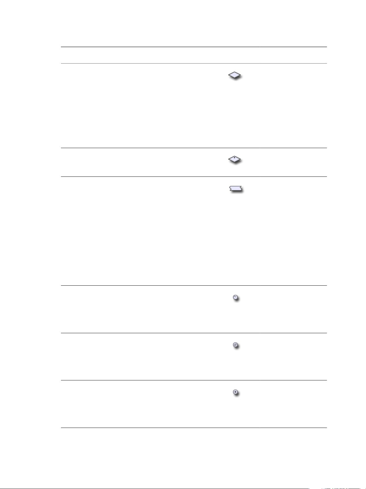
Table 1-3. Schema Elements and Icons
Schema Element
Name Description Icon
Start Workflow The starting point of the workflow. All
workflows contain this element and it
cannot be removed from the workflow
schema. A workflow can have only one start
element. Start elements have one output and
no input.
Scriptable Task General purpose tasks you define. You write
JavaScript functions in this element.
Icon Location in Workflow
editor
Always present in the
Schema tab
Generic workflow palette
VMware, Inc. 19
Page 20
Developing with VMware vCenter Orchestrator
Table 1-3. Schema Elements and Icons (Continued)
Schema Element
Name Description Icon
Decision Boolean function. Decision elements take
one input parameter and return either
true or false. The type of decision the
element makes depends on the type of the
input parameter. Decision elements allow
the workflow to branch into different
directions, depending on the input
parameter the decision element receives. If
the received input parameter corresponds to
an expected value, the workflow continues
along a certain route. If the input is not the
expected value, the workflow continues on
an alternative path.
Custom Decision Boolean function. Custom decisions can take
several input parameters and act upon them
according to custom scripts. Returns either
true or false.
User Interaction Allows users to pass new input parameters
into the workflow. You can design how the
user interaction element presents the
request for input parameters and place
constraints on the parameters that users can
provide. You can set permissions to
determine which users can provide the input
parameters. When a running workflow
arrives at a user interaction element, it enters
a passive state and prompts the user for
input. You can set a timeout period within
which the users can answer. The workflow
resumes according to the data the user
passes to it, or returns an exception if the
timeout period expires. While it is waiting
for the user to respond, the workflow token
is in the waiting state.
Waiting Timer Used by long-running workflows. When a
running workflow arrives at a Waiting
Timer element it enters a passive state. You
set an absolute date at which the workflow
resumes running. While it is waiting for the
date, the workflow token is in the waiting-
signal state.
Waiting Event Used in long-running workflows. When a
running workflow arrives at a Waiting
Event element it enters a passive state. You
define a trigger event that the workflow
awaits before it resumes running. While it is
waiting for the event, the workflow token is
in the waiting-signal state.
End Workflow The end point of the workflow. You can have
multiple end elements in a schema, to
represent the different possible outcomes of
the workflow. End elements have one input
with no output. When a workflow reaches
an End Workflow element, the workflow
token enters the completed state.
Icon Location in Workflow
editor
Generic workflow palette
Generic workflow palette
Generic workflow palette
Generic workflow palette
Generic workflow palette
Generic workflow palette
20 VMware, Inc.
Page 21
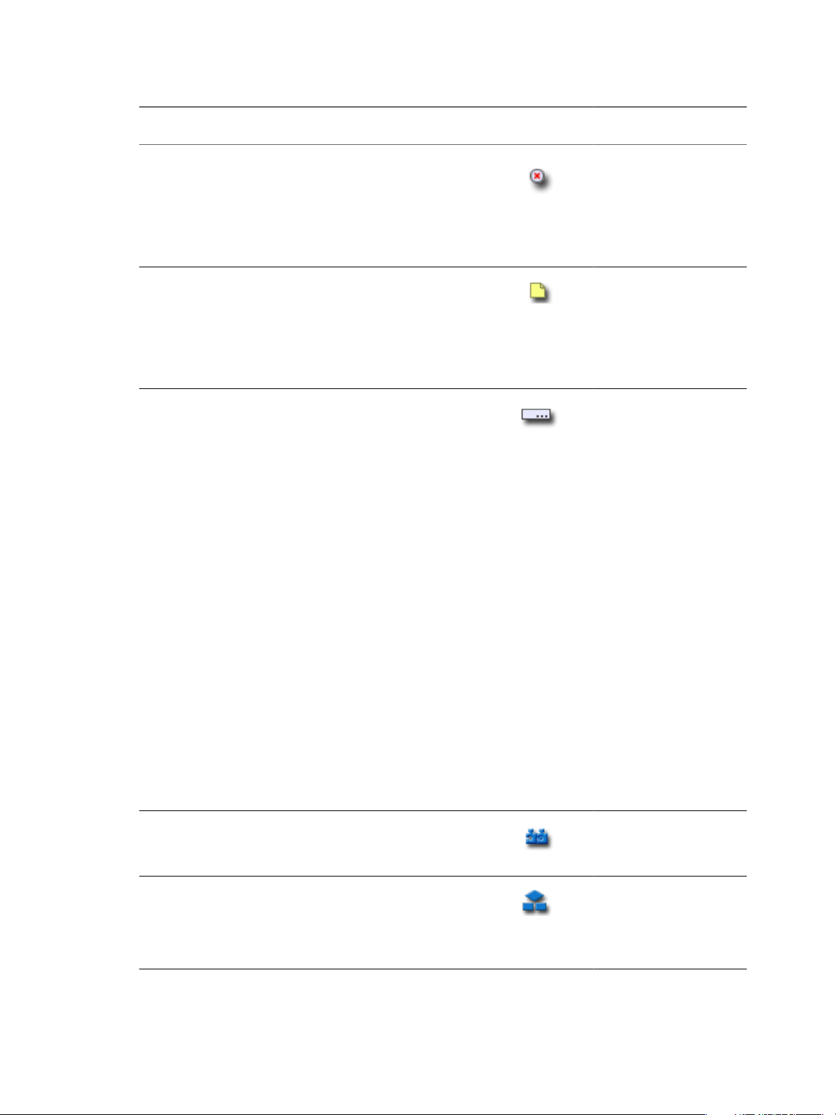
Table 1-3. Schema Elements and Icons (Continued)
Schema Element
Name Description Icon
Thrown Exception Creates an exception and stops the
workflow. Multiple occurrences of this
element can be present in the workflow
schema. Exception elements have one input
parameter, which can only be of the String
type, and have no output parameter. When
a workflow reaches an Exception element,
the workflow token enters the failed state.
Workflow Note Allows you to annotate sections of the
workflow. You can stretch notes to delineate
sections of the workflow. You can change the
background color of the notes to
differentiate between different workflow
zones. Workflow notes provide visual
information only, to help you understand
the schema.
Pre-Defined Task Noneditable scripted elements that perform
standard tasks that workflows commonly
use. The following tasks are predefined:
Basic
n
Sleep
n
Change credential
n
Wait until date
n
Wait for custom event
n
Increase counter
n
Decrease counter
n
Add hours to date
Log
n
System log
n
System warning
n
System error
n
Server log
n
Server warning
n
Server error
n
System+server log
n
System+server warning
n
System+server error
Network
n
HTTP post
n
HTTP get
n
Send custom event
Action Calls on an action from the Orchestrator
libraries of actions. When a workflow
reaches an action element, it calls and runs
that action.
Workflow Starts another workflow synchronously. As
soon as a workflow reaches a workflow
element in its schema, it runs that workflow
as part of its own process. The original
workflow does not continue until the called
workflow completes its run.
Chapter 1 Developing Workflows
Icon Location in Workflow
editor
Generic workflow palette
Generic workflow palette
Basic, Log, and Network
workflow palette
Action & Workflow
workflow palette
Action & Workflow
workflow palette
VMware, Inc. 21
Page 22

Developing with VMware vCenter Orchestrator
Table 1-3. Schema Elements and Icons (Continued)
Schema Element
Name Description Icon
Asynchronous
Workflows
Schedule Workflow Creates a task to run the workflow at a set
Nested Workflows Starts several workflows simultaneously.
Starts a workflow asynchronously. When a
workflow reaches an asynchronous
workflow element, it starts that workflow
and continues its own run. The original
workflow does not wait for the called
workflow to finish before continuing.
time, then the workflow continues its run.
You can choose to nest local workflows and
remote workflows that are in a different
Orchestrator server. You can also run
workflows with different credentials. The
workflow waits until all the nested
workflows complete before it continues its
run.
Icon Location in Workflow
editor
Action & Workflow
workflow palette
Action & Workflow
workflow palette
Action & Workflow
workflow palette
Schema Element Properties
Schema elements have properties that you can define and edit in the Schema tab of the workflow palette.
Edit a Schema Element's Global Properties
You define a schema element's global properties in the schema element's Info tab.
Prerequisites
The Schema tab of the workflow editor must contain elements.
Procedure
1 Click the Schema tab in the workflow editor.
2 Select an element to edit by clicking a schema element in the workflow schema.
The schema element's properties tabs appear at the bottom of the workflow editor.
3 Click the Info tab.
4 Provide a name for the schema element in the Name text box.
This is the name that appears in the schema element in the workflow schema diagram.
5 Click the Interaction text box and select a description from the list.
The Interaction property allows you to select between standard descriptions of how this element interacts
with objects outside of the workflow. This property is for information only.
6 (Optional) Click Color to change the background color of the schema element.
You can highlight certain sections of the schema by changing the color of individual workflow elements.
7 Provide a business status description in the Business Status text box.
The Business Status property is a brief description of what this element does. When a workflow is running,
the workflow token shows the Business Status of each element as it runs. This feature is useful for tracking
workflow status.
22 VMware, Inc.
Page 23

Chapter 1 Developing Workflows
Schema Element Properties Tabs
You access the properties of a schema element by clicking on an element that you have dragged into the
workflow schema. The properties of the element appear in tabs at the bottom of the workflow editor.
Different schema elements have different properties tabs.
Table 1-4. Properties Tabs per Schema Element
Schema Element Property Tab Description Applies to Schema Element Type
Attributes Attributes that elements require
from an external source, such as
the user, an event, or a timer. The
attributes can be a timeout limit,
a time and date, a trigger, or user
credentials.
Decision Defines the decision statement.
The input parameter that the
decision element receives either
matches or does not match the
decision statement, resulting
two possible courses of action.
End Workflow Stops the workflow, either
because the workflow
completed successfully, or
because it encountered an error
and returned an exception.
Exception How this schema element
behaves in the event of an
exception.
External Inputs Input parameters that the user
must provide at a certain
moment while the workflow
runs.
IN The IN binding for this element.
The IN binding defines the way
in which the schema element
receives input from the element
that precedes it in the workflow.
n
User Interaction
n
Waiting Event
n
Waiting Timer
Decision
n
End
n
Exception
n
Action
n
Asynchronous Workflow
n
Exception
n
Nested Workflows
n
Predefined Task
n
Schedule Workflow
n
Scriptable Task
n
User Interaction
n
Waiting Event
n
Waiting Timer
n
Workflow
User Interaction
n
Action
n
Asynchronous Workflow
n
Custom Decision
n
Predefined Task
n
Schedule Workflow
n
Scriptable Task
n
Workflow
VMware, Inc. 23
Page 24

Developing with VMware vCenter Orchestrator
Table 1-4. Properties Tabs per Schema Element (Continued)
Schema Element Property Tab Description Applies to Schema Element Type
Info The schema element's general
OUT The OUT binding for this
Presentation Defines the layout of the input
Scripting Shows the JavaScript function
Visual Binding Shows a graphical
Workflows Selects the workflows to nest. Nested Workflows
properties and description. The
information the Info tab
displays depends on the type of
schema element.
element. The OUT binding
defines the way in which the
schema element binds output
parameters to the workflow
attributes or to the workflow
output parameters.
parameters dialog box the user
sees if the workflow needs user
input while it is running.
that defines the behavior of this
schema element. For
Asynchronous Workflow,
Schedule Workflow, and Action
elements this scripting is readonly. For scriptable task and
custom decision elements, you
edit the JavaScript in this tab.
representation of how the
parameters and attributes of this
schema element bind to the
parameters and attributes of the
elements that come before and
after it in the workflow. This is
another representation of the
element's IN and OUT bindings.
n
Action
n
Asynchronous Workflow
n
Custom Decision
n
Decision
n
Nested Workflows
n
Note
n
Predefined Task
n
Schedule Workflow
n
Scriptable Task
n
User Interaction
n
Waiting Event
n
Waiting Timer
n
Workflow
n
Action
n
Asynchronous Workflow
n
Predefined Task
n
Schedule Workflow
n
Scriptable Task
n
Workflow
User Interaction
n
Action
n
Asynchronous Workflow
n
Custom Decision
n
Predefined Task
n
Schedule Workflow
n
Scriptable Task
n
Action
n
Asynchronous Workflow
n
Predefined Task
n
Schedule Workflow
n
Scriptable Task
n
Workflow
Links and Bindings
Links between elements determine the logical flow of the workflow. Bindings populate elements with data
from other elements by binding input and output parameters to workflow attributes.
To understand links and bindings, you must understand the difference between the logical flow of a workflow
and the data flow of a workflow.
24 VMware, Inc.
Page 25
Chapter 1 Developing Workflows
Logical Flow of a Workflow
The logical flow of a workflow is the progression of the workflow from one element to the next in the schema
as the workflow runs. You define the logical flow of the workflow by linking elements in the schema.
The standard path is the path that the workflow takes through the logical flow if all elements run as expected.
The exception path is the path that the workflow takes through the logical flow if an element does not run as
expected.
Different styles of arrows in the workflow schema denote the different paths that the workflow can take
through its logical flow.
n
A black arrow denotes the standard path that the workflow takes from one element to the next.
n
A green arrow denotes the path that the workflow takes if a Boolean decision element returns true.
n
A red dotted arrow denotes the path that the workflow takes if a Boolean decision element returns
false.
n
A thick red dotted arrow denotes the exception path that the workflow takes if a workflow element does
not run correctly.
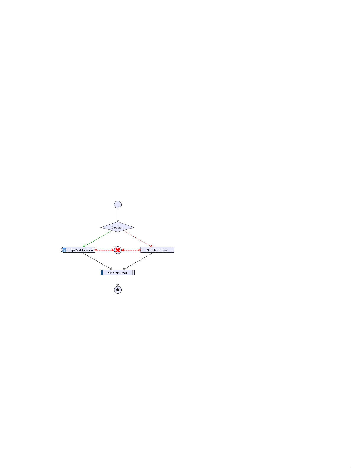
The following figure shows an example workflow schema that demonstrates the different paths that workflows
can take.
Figure 1-1. Different Workflow Paths Through the Logical Flow of the Workflow
This example workflow can take the following paths through its logical flow.
n
Standard path, true decision result, no exceptions.
a The decision element returns true.
b The SnapVMsInResourcePool workflow runs successfully.
c The sendHtmlEmail action runs successfully.
d The workflow ends successfully in the completed state.
n
Standard path, false decision result, no exceptions.
a The decision element returns false.
b The operation the scriptable task element defines runs successfully.
c The sendHtmlEmail action runs successfully.
d The workflow ends successfully in the completed state.
VMware, Inc. 25
Page 26

Developing with VMware vCenter Orchestrator
n
true decision result, exception.
a The decision element returns true.
b The SnapVMsInResourcePool workflow encounters an error.
c The workflow returns an exception and stops in the failed state.
n
false decision result, exception.
a The decision element returns false.
b The operation the Scriptable task element defines encounters an error.
c The workflow returns an exception and stops in the failed state.
Element Links
Links connect schema elements and define the logical flow of the workflow from one element to the next.
Elements can usually set only one outgoing link to another element in the workflow and one exception link to
an element that defines its exception behavior. The outgoing link defines the standard path of the workflow.
The exception link defines the exception path of the workflow. In most cases, a single schema element can
receive incoming standard path links from multiple elements.
The following elements are exceptions to the preceding statements.
n
The Start Workflow element cannot receive incoming links and has no exception link.
n
Exception elements can receive multiple incoming exception links, and have no outgoing or exception
links.
n
Decision elements have two outgoing links that define the paths the workflow takes depending on the
decision's true or false result. Decisions have no exception link.
n
End Workflow elements cannot have outgoing links or exception links.
Create Standard Path Links
You link elements by connecting them using the connector tool in the Schema tab of the workflow editor.
When you link one element to another, you always link the elements in the order in which they run in the
workflow. You always start from the element that runs first to create a link between two elements.
Prerequisites
To link elements, you must have the workflow editor open and the Schema must contain elements.
Procedure
1 Click the connector tool button in the toolbar at the top of the Schema tab to activate the connector tool.
2 Click an element to link to another element.
3 Move the pointer over the highlighted element to link to another element.
A black rectangle appears at the bottom of the element.
4 Left-click inside the element near the black rectangle, hold down the left mouse button, and move the
pointer to the target element.
An arrow appears between the two elements and the target element turns green.
5 Release the left mouse button.
The arrow remains between the two elements.
A standard path now links the elements.
26 VMware, Inc.
Page 27
Chapter 1 Developing Workflows
What to do next
The elements are joined, but you have not defined the data flow. You must define the IN and OUT bindings
to bind incoming and outgoing data to workflow attributes.
Data Flow of a Workflow
The data flow of a workflow is the manner in which workflow element input and output parameters bind to
workflow attributes as each element of the workflow runs. You define the data flow of a workflow by using
schema element bindings.
When an element in the workflow schema runs, it requires data in the form of input parameters. It takes the
data for its input parameters by binding to a workflow attribute that you set when you create the workflow,
or by binding to an attribute that a preceding element in the workflow set when it ran.
The element processes the data, possibly transforms it, and generates the results of its run in the form of output
parameters. The element binds its resulting output parameters to new workflow attributes that it creates. Other
elements in the schema can bind to these new workflow attributes as their input parameters. The workflow
can generate the attributes as its output parameters at the end of its run.
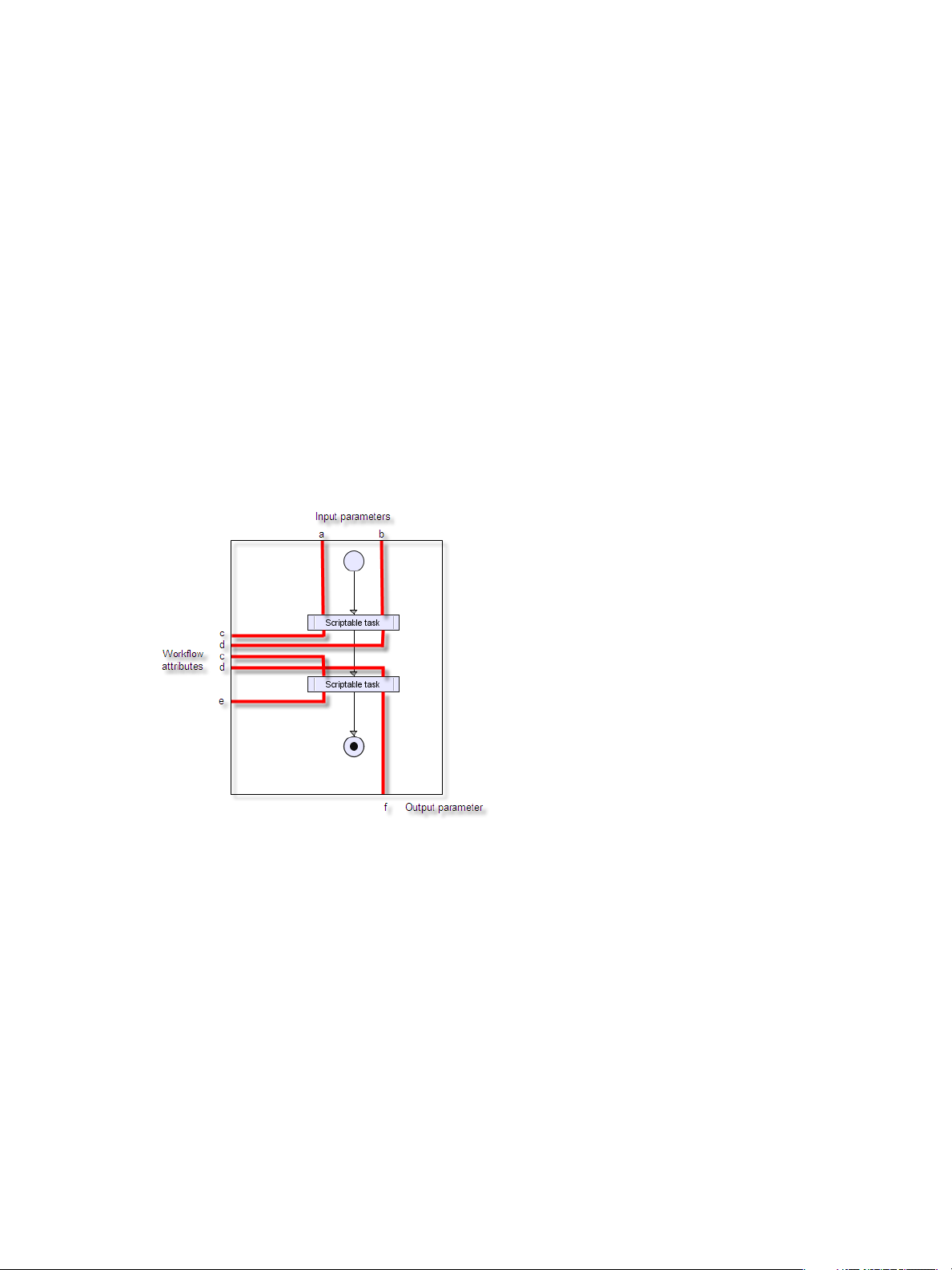
Figure 1-2 shows a very simple workflow. The black arrows represent the element linking and the logical flow
of the workflow. The red lines show the data flow of the workflow.
Figure 1-2. Example of Workflow Data Flow
The data flows through the workflow as follows.
1 The workflow starts with input parameters a and b.
2 The first element processes parameter a and binds the result of the processing to workflow attribute c.
3 The first element processes parameter b and binds the result of the processing to workflow attribute d.
4 The second element takes workflow attribute c as an input parameter, processes it, and binds the resulting
output parameter to workflow attribute e.
5 The second element takes workflow attribute d as an input parameter, processes it, and generates output
parameter f.
6 The workflow ends and generates workflow attribute f as its output parameter, the result of its run.
VMware, Inc. 27
Page 28

Developing with VMware vCenter Orchestrator
Element Bindings
You must bind all workflow element input and output parameters to workflow attributes. Bindings set data
in the elements, and define the output and exception behavior of the elements. Links define the logical flow
of the workflow, whereas bindings define the data flow.
To set data in an element, generate ouput parameters from the element after processing, and handle any errors
that might occur when the element runs, you must set the element binding.
IN bindings
Set a schema element's incoming data. You bind the element's local input
parameters to source workflow attributes. The IN tab lists the element's input
parameters in the Local Parameter column. The IN tab lists the workflow
attributes to which the local parameter binds in the Source Parameter column.
The tab also shows the parameter type and a description of the parameter.
OUT bindings
Change workflow attributes and generate output parameters when an element
finishes its run. The OUT tab lists the element's output parameters in the Local
Parameter column. The OUT tab lists the workflow attributes to which the local
parameter binds in the Source Parameter column. The tab also shows the
parameter type and a description of the parameter.
Exception bindings
Link to exception handlers if the element encounters an exception when it runs.
You must use IN bindings to bind every attribute or input parameter you use in a schema element to a workflow
attribute. If the element changes the values of the input parameters it receives when it runs, you must bind
them to a workflow attribute by using an OUT binding. Binding the element's output parameters to workflow
elements allows other elements that follow it in the workflow schema to take those output parameters as their
input parameters.
A common mistake when creating workflows is to forget to bind output parameter values to reflect the changes
the element makes to the workflow attributes.
IMPORTANT When you add an element that requires input and output parameters of a type that you already
defined in the workflow, Orchestrator sets the bindings to these parameters. You must check that the
parameters Orchestrator binds are correct, in case the workflow defines different parameters of the same type
to which the element could bind.
Define Element Bindings
After you link elements to create the logical flow of the workflow, you define element bindings to define how
each element processes the data it receives and generates.
Prerequisites
You must have a workflow schema in the Schema tab of the workflow editor, and have created links between
the elements.
Procedure
1 Click an element on which to set the bindings.
The element is highlighted and the element attributes tabs appear at the bottom of the Schema tab.
28 VMware, Inc.
Page 29

Chapter 1 Developing Workflows
2 Click the IN tab.
The contents of the IN tab depend on the type of element you selected.
n
If you selected a predefined task, workflow, or action element, the IN tab lists the possible local input
parameters for that type of element, but the binding is not set.
n
If you selected another type of element, you can select from a list of input parameters and attributes
you already defined for the workflow by right-clicking in the IN tab and selecting Bind to workflow
attribute/parameter.
n
If the required attribute does not exist yet, you can create it by right-clicking in the IN tab and selecting
Bind to workflow attribute/parameter > Create attribute/parameter in workflow.
3 If an appropriate parameter exists, choose an input parameter to bind, and click the Not set button in the
Source Parameter text box.
A list of possible source parameters and attributes to bind to appears.
4 Choose a source parameter to bind to the local input parameter from the list proposed.
5 (Optional) If you have not defined the source parameter to which to bind, you can create it by clicking the
Create attribute/parameter in workflow link in the parameter selection dialog box.
6 Click the OUT tab.
The contents of the OUT tab depend on the type of element you selected.
n
If you selected a predefined task, workflow, or action element, the OUT tab lists the possible local
output parameters for that type of element, but the binding is not set.
n
If you selected another type of element, you can select from a list of output parameters and attributes
you defined for the workflow by right-clicking in the OUT tab and selecting Bind to workflow
attribute/parameter.
n
If the required attribute does not exist, you can create it by right-clicking in the IN tab and selecting
Bind to workflow attribute/parameter > Create attribute/parameter in workflow.
7 Choose a parameter to bind.
8 Click the Source Parameter > Not set button.
9 Choose a source parameter to bind to the input parameter.
10 (Optional) If you did not define the parameter to which to bind, you can create it by clicking the Create
attribute/parameter in workflow button in the parameter selection dialog box.
You defined the input parameters that the element receives and the output parameters that it generates, and
bound them to workflow attributes and parameters.
What to do next
You can create forks in the path of the workflow by defining decisions.
Decisions
Workflows can implement decision functions that define different courses of action according to a Boolean
true or false statement.
Decisions are forks in the workflow. Workflow decisions are made according to inputs provided by you, by
other workflows, by applications, or by the environment in which the workflow is running. The value of the
input parameter that the decision element receives determines which branch of the fork the workflow takes.
For example, a workflow decision might receive the power status of a given virtual machine as its input. If the
virtual machine is powered on, the workflow takes a certain path through its logical flow. If the virtual machine
is powered off, the workflow takes a different path.
VMware, Inc. 29
Page 30

Developing with VMware vCenter Orchestrator
Decisions are always Boolean functions. The only possible outcomes for each decision are true or false.
Custom Decisions
Custom decisions differ from standard decisions in that you define the decision statement in a script. Custom
decisions return true or false according to the statement you define, as the following example shows.
if (
decision_statement
return true;
}else{
return false;
}
){
Create Decision Element Links
Decision elements differ from other elements in that they have only true or false output parameters. Decision
elements have no exception linking.
Prerequisites
You must have the workflow editor open and the Schema tab must contain elements, including at least one
decision element.
Procedure
1 Click a decision element to link to two other elements to define two possible branches in the workflow.
2 Click the connector tool button in the toolbar at the top of the Schema tab.
3 Move the pointer over the highlighted decision element to link to two other elements.
n
If you hold the pointer over the left side of the decision element, a green arrow appears at the bottom
of the element. The green arrow represents the true path the workflow takes if the input parameter
or attribute received by the decision element matches the decision statement.
n
If you hold the pointer over the right side of the decision element, a red arrow appears at the bottom
of the element. The red arrow represents the false path the workflow takes if the input parameter or
attribute received by the decision element does not match the decision statement.
4 Left-click inside the left side of the decision element, hold down the left mouse button, and move the
pointer to the target element.
A green arrow appears between the two elements and the target element turns green.
5 Release the left mouse button.
The green arrow remains between the two elements. You have defined the path the workflow takes when
the decision element receives the expected value.
6 Left-click inside the right side of the decision element, hold down the left mouse button, and move the
pointer to the target element.
A dotted red arrow appears between the two elements and the target element turns green.
7 Release the left mouse button.
The dotted red arrow remains between the two elements. You have defined the path the workflow takes
when the decision element receives unexpected input.
You have defined two possible true or false paths for the workflow to take, depending on the input parameter
or attribute the decision element receives.
30 VMware, Inc.
Page 31

Chapter 1 Developing Workflows
What to do next
The decision element is linked to two other elements, but you did not define how the workflow determines
which path to take. You must define the decision statement.
Create Workflow Branches Using Decisions
Decision elements are simple Boolean functions that you use to create branches in workflows. Decision
elements determine whether or not the input received matches the decision statement you set. As a function
of this decision, the workflow continues its course along one of two possible paths.
Prerequisites
You must have a decision element linked to two other elements in the schema in the workflow editor before
you define the decision.
Procedure
1 Click the decision element.
2 Click the Decision tab in the element properties tabs at the bottom of the Schema tab.
3 Click the Not Set (NULL) link to select the possible source input parameter for this decision.
A dialog box appears, which lists all the attributes and input parameters you defined in this workflow.
4 Select an input parameter from the list by double-clicking it.
5 (Optional) If you did not define the source parameter to which to bind, you can create it by clicking the
Create attribute/parameter in workflow link in the parameter selection dialog box.
6 Select a decision statement from the drop-down menu.
The statements the menu proposes are contextual, and differ according to the type of input parameter
selected.
7 Add a value for the statement to match.
Depending on the input type and the statement you select, you might see a Not Set (NULL) link in the
value text box. Clicking this link gives you a predefined choice of values. Otherwise, for example for
Strings, this is a text box in which you provide a value.
You defined a statement for the decision element. When the decision element receives the input parameter, it
compares the value of the input parameter to the value in the statement and determines whether the statement
is true or false.
What to do next
You must set up how the workflow handles exceptions.
Exception Handling
Exception handling catches any errors that occur when a schema element runs. Exception handling defines
how the schema element behaves when the error occurs.
All elements in a workflow, except for decisions and start and end elements, contain a specific output parameter
type that serves only for handling exceptions. If an element encounters an error during its run, it can send an
error signal to an exception handler. Exception handlers catch the error and react according to the errors they
receive. If the exception handlers you define cannot handle a certain error, you can bind an element's exception
output parameter to an Exception element, which ends the workflow run in the failed state.
VMware, Inc. 31
Page 32

Developing with VMware vCenter Orchestrator
Exceptions act as a try and catch sequence within a workflow element. If you do not need to handle a given
exception in an element, you do not have to bind that element's exception output parameter.
The output parameter type for exceptions is always an errorCode object.
Create Exception Bindings
Elements can set bindings that define how the workflow behaves if it encounters an error in that element.
Prerequisites
The Schema tab of the workflow editor must contain elements.
Procedure
1 Click the element on which to set the exception binding.
2 Click the connector tool button in the toolbar at the top of the Schema tab or hold down Ctrl and move
the pointer over the right of the element for which to set the exception binding.
A red rectangle appears on the right of the element.
3 Left-click inside the element near the red rectangle, hold down the left mouse button, and move the pointer
to the target element.
A thick dotted red arrow links the two elements. The target element defines the behavior of the workflow
if the element that links to it encounters an error.
4 Click the element that links to the exception handling element.
5 Click the Exceptions tab in the schema element properties tabs at the bottom of the Schema tab.
6 Click the Not set button to set the Output Exception Binding value.
n
Select a parameter to bind to the exception output parameter from the exception attribute binding
dialog box.
n
Click Create parameter/attribute in workflow to create an exception output parameter.
7 Click the target element that defines the exception handling behavior.
8 Click the IN tab in the schema element properties tabs at the bottom of the Schema tab.
9 Right-click in the IN tab and select Bind to workflow parameter/attribute.
10 Select the exception output parameter and click Select.
11 Click the OUT tab for the exception handling element in the schema element properties tabs at the bottom
of the Schema tab
12 Define the behavior of the exception handling element.
n
Right-click in the OUT tab and select Bind to workflow parameter/attribute to select an output
parameter for the exception handling element to generate.
n
Click the Scripting tab and use JavaScript to define the behavior of the exception handling element.
You defined how the element handles exceptions.
What to do next
You must define how to obtain input parameters from users when they run the workflow.
32 VMware, Inc.
Page 33

Chapter 1 Developing Workflows
Obtaining Input Parameters from Users When a Workflow Starts
If a workflow requires input parameters, it opens a dialog box in which users enter the required input parameter
values when it runs. You can organize the content and layout, or presentation, of this dialog box in
Presentation tab in the workflow editor.
The way you organize parameters in the Presentation tab translates into the input parameters dialog box when
the workflow runs, and in the dialog box that opens when you run a workflow from a Web view.
The Presentation tab also allows you to add descriptions of the input parameters to help users when they
provide input parameters. You can also set properties and constraints on parameters in the Presentation tab
to limit the parameters that users provide. If the parameters the user provides do not meet the constraints you
set in the Presentation tab, the workflow will not run.
IMPORTANT The use of OGNL expressions in workflow presentations is deprecated as of Orchestrator 4.1.
Using OGNL expressions in workflow presentations is not supported in releases of Orchestrator later than 4.1.
n
Creating the Input Parameters Dialog Box In the Presentation Tab on page 33
You define the layout of the dialog box in which users provide input parameters when they run a
workflow in the Presentation tab of the workflow editor.
n
Setting Parameter Properties on page 35
Orchestrator allows you to define properties to qualify the input parameter values that users provide
when they run workflows. The parameter properties you define impose limits on the types and values
of the input parameters the users provide.
Creating the Input Parameters Dialog Box In the Presentation Tab
You define the layout of the dialog box in which users provide input parameters when they run a workflow
in the Presentation tab of the workflow editor.
The Presentation tab allows you to group input parameters into categories and to define the order in which
these categories appear in the input parameters dialog box.
Presentation Descriptions
You can add an associated description for each parameter or group of parameters, which appears in the input
parameters dialog box. The descriptions provide information to the users to help them provide the correct
input parameters. You can enhance the layout of the description text by using HTML formatting.
Defining Presentation Input Steps
By default, the input parameters dialog box lists all the required input parameters in a single list. To help users
enter input parameters, you can define nodes, called input steps, in the presentation tab. Input steps group
input parameters of a similar nature. The input parameters under an input step appear in a distinct section in
the input parameters dialog box when the workflow runs.
Defining Presentation Display Groups
Each input step can have nodes of its own called display groups. The display groups define the order in which
parameter input text boxes appear within their section of the input parameters dialog box. You can define
display groups independently of input steps.
VMware, Inc. 33
Page 34

Developing with VMware vCenter Orchestrator
Create the Presentation of the Input Parameters Dialog Box
You create the presentation of the dialog box in which users provide input parameters when they run a
workflow in the Presentation tab in the workflow editor.
Prerequisites
You must have created a workflow and a defined list of input parameters.
Procedure
1 In the workflow editor, click the Presentation tab.
By default, all of the workflow's parameters appear under the main Presentation node in the order in
which you create them.
2 Right-click the Presentation node and select Create new step.
A New Step node appears under the Presentation node.
3 Double-click the New Step node to provide it with an appropriate name and press Enter.
This name appears as a section header in the input parameters dialog box when the workflow runs.
4 Click the input step and add a description in the General tab in the bottom half of the Presentation tab.
This description appears in the input parameters dialog box to provide information to the users to help
them provide the correct input parameters. You can enhance the layout of the description text by using
HTML formatting.
5 Right-click the input step you created and select Create display group.
A New Group node appears under the input step node.
6 Double-click the New Group node and provide it with an appropriate name.
This name appears as a subsection header in the input parameters dialog box when the workflow runs.
7 Click the display group and add a description in the General tab in the bottom half of the Presentation
tab.
This description appears in the input parameters dialog box. You can enhance the layout of the description
text by using HTML formatting. You can add a parameter value to a group description by using an OGNL
statement, such as ${#param}.
8 Repeat the preceding steps until you have created all the input steps and display groups to appear in the
input parameters dialog box when the workflow runs.
9 Drag parameters from under the Presentation node to the steps and groups of your choice.
You created the layout of the input parameters dialog box through which users provide input parameter values
when the workflow runs.
What to do next
You must set the parameter properties.
34 VMware, Inc.
Page 35

Chapter 1 Developing Workflows
Setting Parameter Properties
Orchestrator allows you to define properties to qualify the input parameter values that users provide when
they run workflows. The parameter properties you define impose limits on the types and values of the input
parameters the users provide.
Every parameter can have several properties. You define an input parameter's properties in the Properties tab
for a given parameter in the Presentation tab.
Parameter properties validate the input parameters and modify the way that text boxes appear in the input
parameters dialog box. Some parameter properties can create dependencies between parameters.
Static and Dynamic Parameter Property Values
A parameter property value can be either static or dynamic. Static property values remain constant. If you set
a property value to static, you set or select the property's value from a list that the workflow editor generates
according to the parameter type.
Dynamic property values depend on the value of another parameter or attribute. You define the functions by
which dynamic properties obtain values by using an object graph navigation language (OGNL) expression. If
a dynamic parameter property value depends on the value of another parameter property value and the other
parameter property value changes, the OGNL expression recalculates and changes the dynamic property
value.
IMPORTANT The use of OGNL expressions in workflow presentations is deprecated as of Orchestrator 4.1.
Using OGNL expressions in workflow presentations is not supported in releases of Orchestrator later than 4.1.
Set Parameter Properties
When a workflow starts, it validates input parameter values from users against any parameter properties that
you set.
Prerequisites
You must have a workflow and defined a list of input parameters before setting the parameter constraints.
Procedure
1 In the workflow editor, click the Presentation tab.
2 Click a parameter in the Presentation tab.
The parameter's General and Properties tabs appear at the bottom of the Presentation tab.
3 Click the parameter's Properties tab.
4 Right-click in the Properties tab and select Add property.
A dialog box opens, presenting a list of the possible properties for a parameter of the type selected.
5 Select a property from the list presented in the dialog box and click OK.
The property appears in the Properties tab.
VMware, Inc. 35
Page 36

Developing with VMware vCenter Orchestrator
6 Under Value, make the property value either static or dynamic by selecting the corresponding symbol
from the drop-down menu.
Option Description
7 If you set the property value to static, you select a property value according to the type of parameter for
which you are setting the properties.
8 If you set the property value to dynamic, you define the function to obtain the parameter property value
by using an OGNL expression.
The workflow editor provides help writing the OGNL expression.
a
Click the icon to obtain a list of all the attributes and parameters defined by the workflow that
this expression can call upon.
b
Click the
icon to obtain a list of all the actions in the Orchestrator API that return an output
parameter of the type for which you are defining the properties.
Clicking items in the proposed lists of parameters and actions adds them to the OGNL expression.
Static property
Dynamic property
9 Click Save at the bottom of the workflow editor.
You defined the properties of the workflow's input parameters.
What to do next
Validate and debug the workflow.
Workflow Input Parameter Properties
You can set parameter properties to constrain the input parameters that users provide when they run
workflows.
Different parameter types can have different properties.
Table 1-5. Workflow Input Parameter Properties
Parameter Property Parameter Type Description
Maximum string length String Sets a maximum length for the
parameter.
Minimum string length String Sets a minimum length for the
parameter.
Matching regular expression String Validates the input using a regular
expression.
Maximum number value Number Sets a maximum value for the
parameter.
Minimum number value Number Sets a minimum value for the
parameter.
Number format Number Formats the input for the parameter.
Mandatory Any Makes the parameter mandatory.
36 VMware, Inc.
Page 37

Table 1-5. Workflow Input Parameter Properties (Continued)
Parameter Property Parameter Type Description
Chapter 1 Developing Workflows
Predefined answers All simple types Pre-defines a list of possible values for
Predefined list of elements Any simple or complex types Pre-defines a list of possible values for
Show parameter input Any Shows or hides a parameter text box in
Hide parameter input Any Similar to Show parameter input, but
Matching expression Any parameter type obtained from a
plug-in
Show in inventory Any parameter type obtained from a
plug-in
Specify a root object to be shown in the
chooser. Root object is provided from
a parameter or attribute.
Select as Any parameter type obtained from a
Default value Any Default value for this parameter.
Custom validation OGNL scriptable validation If the OGNL expression returns a string,
Auto start Boolean Starts the workflow automatically.
Mandatory input Boolean Makes this parameter mandatory. The
Data binding Any Binds to a property that you have
Authorized only Any parameter type obtained from a
Multi-lines text input Any Allows users to enter multiple lines of
Any parameter type obtained from a
plug-in
plug-in
plug-in
the property as an array of simple types.
You either define the array manually or
the property calls an action that returns
an array of objects of the appropriate
type.
the property as an array of simple or
complex types. Calls an action that
returns an array of objects of the
appropriate type.
the presentation dialog box, depending
on the value of a preceding Boolean
parameter.
takes the negative value of a previous
Boolean parameter.
The input parameter matches a given
expression.
If set, you can run the present workflow
on any object of this type by rightclicking it in the inventory view and
selecting Run workflow.
Specifies the root object if the selector for
this parameter is a hierarchical list
selector.
Use a list or hierarchical list selector to
select the parameter.
the validation shows this string as the
text of the error result.
workflow will not run without it.
already defined in another parameter.
Only authorized users can access this
parameter.
text in the input parameters dialog box.
Predefined Constant Values for OGNL Expressions
You can use predefined constants when you create OGNL expressions to obtain dynamic parameter property
values.
Orchestrator defines the following constants for use in OGNL expressions.
VMware, Inc. 37
Page 38

Developing with VMware vCenter Orchestrator
Table 1-6. Predefined OGNL Constant Values
Constant Value Description
${#__current}
${#__username}
${#__userdisplayname}
${#__serverurl}
${#__datetime}
${#__date}
${#__timezone}
Current value of the custom validation property or matching
expression property
User name of the user who started the workflow
Display name of the user who started the workflow
URL containing the IP address of the server from which the
user starts the workflow. The URL consists of the server IP
address and a lookup port:
{ServerIP}:{lookupPort}
Current date and time
Current date, with time set to 00:00:00
Current timezone
(Optional) Requesting User Interactions While a Workflow Runs
A workflow can sometimes require additional input parameters from an outside source while it runs. These
input parameters can come from another application or workflow, or the user can provide them directly.
For example, if a certain event occurs while a workflow runs, the workflow can request human interaction to
decide what course of action to take. The workflow waits before continuing, either until the user responds to
the request for information, or until the waiting time exceeds a possible timeout period. If the waiting time
exceeds the timeout period, the workflow returns an exception.
The default attributes for user interactions are security.group and timeout.date. When you set the
security.group attribute to a given LDAP user group, you limit the permission to respond to the user
interaction request to members of that user group.
When you set the timeout.date attribute, you set a time and date until which the workflow waits for the
information from the user. You can set an absolute date, or you can create a scripted workflow element to
calculate a time relative to the current time.
Procedure
1 Add a User Interaction to a Workflow on page 39
You request input parameters from users during a workflow run by adding a User Interaction schema
element to the workflow. When a workflow encounters a User Interaction element, it suspends its run
and waits for the user to provide the data that it requires.
2 Set the User Interaction security.group Attribute on page 39
The security.group attribute of a user interaction element sets which users or groups of users have
permission to respond to the user interaction.
3 Set the timeout.date Attribute to an Absolute Date on page 40
You set the timeout.date attribute for a user interaction to set how long the workflow waits for a user
to respond to a user interaction.
4 Calculate a Relative Timeout for User Interactions on page 41
You can calculate in a Date object a relative time and date at which a user interaction times out.
5 Set the timeout.date Attribute to a Relative Date on page 42
You can set the timeout.date attribute of a User Interaction element to a relative time and date by binding
it to a Date object. You define the object in a scripted function.
38 VMware, Inc.
Page 39

Chapter 1 Developing Workflows
6 Define the External Inputs for a User Interaction on page 43
You specify the information that users must provide during a workflow run as the input parameters of
a user interaction.
7 Define User Interaction Exception Behavior on page 44
If a user does not provide the input parameters within the timeout period, the user interaction returns
an exception. You can define the exception behavior in a scripted function.
8 Create the Input Parameters Dialog Box for the User Interaction on page 45
Users provide input parameters during a workflow run in an input parameters dialog box, in the same
way that they provide input parameters when a workflow first starts.
9 Respond to a Request for a User Interaction on page 46
Workflows that require interactions from users during their run suspend their run either until the user
provides the required information or until the workflow times out.
Add a User Interaction to a Workflow
You request input parameters from users during a workflow run by adding a User Interaction schema element
to the workflow. When a workflow encounters a User Interaction element, it suspends its run and waits for
the user to provide the data that it requires.
Prerequisites
n
Create a workflow
n
Open the workflow for editing in the workflow editor
n
Add some elements to the workflow schema
Procedure
1 Drag a User Interaction element to the appropriate position in the workflow schema.
2 Link the User Interaction element to the elements that precede and follow it.
3 Click the User Interaction element to display its properties tabs in the bottom half of the Schema tab.
4 Provide a name and a description for the user interaction in the Info tab.
5 Click Save.
You added a user interaction element to a workflow. When the workflow reaches this element, it waits for
information from the user before continuing its run.
What to do next
Set the security.group attribute of the user interaction to limit permission to respond to the user interaction
to a user or user group. See “Set the User Interaction security.group Attribute,” on page 39.
Set the User Interaction security.group Attribute
The security.group attribute of a user interaction element sets which users or groups of users have permission
to respond to the user interaction.
Prerequisites
n
Create a workflow.
n
Open the workflow for editing in the workflow editor.
n
Add some elements and a user interaction to the workflow schema.
VMware, Inc. 39
Page 40

Developing with VMware vCenter Orchestrator
n
Identify an LDAP user group to respond to the user interaction request.
Procedure
1 Click the User Interaction element in the workflow schema.
2 Click the Attributes tab for the user interaction.
3 Click Not set for the security.group source parameter to set which users can respond to the user
interaction.
4 (Optional) Select NULL to allow all users to respond to the request for user interaction.
5 To limit the permission to respond to a specific user or user group, click Create parameter/attribute in
workflow.
The Parameter information dialog box opens.
6 Name the parameter.
7 Select Create workflow ATTRIBUTE with the same name to create the LdapGroup attribute in the
workflow.
8 Click Not set for the parameter value to open the LdapGroup selection box.
9 Type the name of the LDAP user group in the Filter text box.
10 Select the LDAP user group from the list and click Select.
For example, selecting the Administrators group means that only members of that group can respond to
this request for user interaction.
You limited the permission to respond to the user interaction request.
11 Click OK to close the Parameter information dialog box.
You set the security.group attribute for the user interaction.
What to do next
Set the timer.date attribute to set the timeout period for the user interaction.
n
To set the timeout to an absolute date and time, see “Set the timeout.date Attribute to an Absolute
Date,” on page 40.
n
To create a function to calculate a timeout that is relative to the current date and time, see “Calculate a
Relative Timeout for User Interactions,” on page 41.
Set the timeout.date Attribute to an Absolute Date
You set the timeout.date attribute for a user interaction to set how long the workflow waits for a user to respond
to a user interaction.
You set an absolute time and date in the Date object. When the time on the given date arrives, the workflow
that is waiting for a user interaction times out and ends in the Failed state. For example, you can set the user
interaction to timeout at midday on February 12th. To calculate a timeout that is relative to the current time
and date, see “Calculate a Relative Timeout for User Interactions,” on page 41.
Prerequisites
n
Open a workflow for editing in the workflow editor.
n
Add a user interaction element to the workflow schema.
n
Set the security.group attribute for the user interaction.
40 VMware, Inc.
Page 41

Chapter 1 Developing Workflows
Procedure
1 Click the User Interaction element in the workflow schema.
2 Click the Attributes tab for the user interaction.
3 Click Not set for the timeout.date source parameter to set the timeout parameter value.
4 (Optional) Select NULL to allow the user interaction to set the workflow to wait indefinitely for the user
to respond to the user interaction.
5 Click Create parameter/attribute in workflow to set the workflow to fail after a timeout period.
The Parameter information dialog box opens.
6 Name the parameter.
7 Select Create workflow ATTRIBUTE with the same name to create a Date attribute in the workflow.
8 Click Not set for the parameter Value.
9 Use the calendar to select an absolute date and time until which the workflow waits for the user to respond.
10 Click OK to close the calendar.
11 Click OK to close the Parameter information dialog box.
You set the timeout.date attribute to an absolute date. The workflow times out if the user does not respond
to the user interaction before this time and date.
What to do next
Define the external input parameters that the user interaction requires from the user. See “Define the External
Inputs for a User Interaction,” on page 43.
Calculate a Relative Timeout for User Interactions
You can calculate in a Date object a relative time and date at which a user interaction times out.
You can set an absolute time and date in a Date object. When the time on the given date arrives, the request
for a user interaction times out. Alternatively, you can create a workflow element that calculates and generates
a relative Date object according to a function that you define. For example, you can create a relative Date object
that adds 24 hours to the current time.
Prerequisites
n
Open a workflow for editing in the workflow editor.
n
Add a user interaction element to the workflow schema.
n
Set the security.group attribute for the user interaction.
Procedure
1 Drag a Scriptable Task element from the Generic menu to the schema of a workflow, above the element
that requires the relative Date object for its timeout.date attribute.
2 Link the Scriptable Task element to the elements that precede and follow it in the workflow schema.
3 Click the Scriptable Task element to show its properties tabs in the bottom half of the Schema tab.
4 Provide a name and description for the scripted workflow element in the Info properties tab.
5 Right-click in the OUT properties tab, and select Bind to workflow parameter/attribute.
VMware, Inc. 41
Page 42

Developing with VMware vCenter Orchestrator
6 Click Create parameter/attribute in workflow to create a workflow attribute.
a Name the attribute timerDate.
b Select Date from the list of attribute types.
c Select Create workflow ATTRIBUTE with the same name.
d Leave the attribute value set to Not set, because a scripted function will provide this value.
e Click OK.
7 Click the Scripting tab for the scripted workflow element.
8 Define a function to calculate and generate a Date object named timerDate in the scripting pad in the
Scripting tab.
For example, you can create a Date object by implementing the following JavaScript function, in which
the timeout period is a relative delay in milliseconds.
timerDate = new Date();
System.log( "Current date : '" + timerDate + "'" );
timerDate.setTime( timerDate.getTime() + (86400 * 1000) );
System.log( "Timer will expire at '" + timerDate + "'" );
The preceding example JavaScript function defines a Date object that obtains the current date and time by
using the getTime method and adds 86,400,000 milliseconds, or 24 hours. The Scriptable Task element
generates this value as its output parameter.
9 Click Save.
You created a function that calculates a time and date relative to the current time and date and generates a
Date object. A User Interaction element can receive this Date object as an input parameter to set the timeout
period until which it waits for input from the user. When the workflow arrives at the User Interaction element,
it suspends its run and waits either until the user provides the required information, or for 24 hours before it
times out.
What to do next
You must bind the Date object to the User Interaction element's timeout.date parameter. See “Set the
timeout.date Attribute to a Relative Date,” on page 42.
Set the timeout.date Attribute to a Relative Date
You can set the timeout.date attribute of a User Interaction element to a relative time and date by binding it
to a Date object. You define the object in a scripted function.
If you create a relative Date object in a scripted function, you can bind the timeout.date attribute of a user
interaction to this Date object. For example, if you bind the timeout.date attribute to a Date object that adds 24
hours to the current time, the user interaction times out after waiting for 24 hours.
Prerequisites
n
Add a user interaction element to the workflow schema.
n
Set the security.group attribute for the user interaction.
n
Create a scripted function that calculates a relative time and date and encapsulates it in a Date object in
the workflow. See “Calculate a Relative Timeout for User Interactions,” on page 41.
Procedure
1 Click the User Interaction element in the workflow schema.
2 Click the Attributes tab for the user interaction.
42 VMware, Inc.
Page 43

Chapter 1 Developing Workflows
3 Click Not set for the timeout.date source parameter to set the timeout parameter value.
4 Select the Date object that encapsulates a relative time and date that you defined in a scripted function and
click Select.
You set the timeout.date attribute to a relative date and time that a scripted function calculates.
What to do next
Define the external input parameters that the user interaction requires from the user. See “Define the External
Inputs for a User Interaction,” on page 43.
Define the External Inputs for a User Interaction
You specify the information that users must provide during a workflow run as the input parameters of a user
interaction.
When a workflow reaches a user interaction element, it waits until a user provides the information that the
user interaction requires as its input parameters.
Prerequisites
n
Add a user interaction element to the workflow schema.
n
Set the security.group attribute for the user interaction.
n
Set the timer.date attribute for the user interaction
Procedure
1 Click the User Interaction element in the workflow schema.
2 Click the External Inputs tab.
3 Right-click in the External Inputs tab and select Bind to workflow parameter/attribute to define the
parameters that the user must provide in the user interaction.
4 (Optional) If you already defined the input parameters in the workflow, select the parameters from the
proposed list.
5 Click Create parameter/attribute in the workflow to create a workflow attribute to bind to the input
parameter that the user provides.
6 Give the parameter an appropriate name.
7 Select the input parameter type from the list of types by searching for an object type in the Filter box.
For example, if the user interaction requires the user to provide a virtual machine as an input parameter,
select VC:VirtualMachine.
8 Select Create workflow ATTRIBUTE with the same name to bind the input parameter that the user
provides to a new attribute in the workflow.
9 Leave the input parameter value set to Not set.
The user provides this value when they respond to the user interaction during the workflow run.
10 Click OK to close the Parameter information dialog box.
You defined the input parameters that the user provides during a user interaction.
What to do next
Define the exception behavior if the user interaction encounters an error. See “Define User Interaction
Exception Behavior,” on page 44.
VMware, Inc. 43
Page 44

Developing with VMware vCenter Orchestrator
Define User Interaction Exception Behavior
If a user does not provide the input parameters within the timeout period, the user interaction returns an
exception. You can define the exception behavior in a scripted function.
If you do not define the action for the workflow to take if the user interaction times out, the workflow ends in
the Failed state. Defining the exception behavior is a good workflow development practice.
Prerequisites
n
Add a user interaction element to the workflow schema.
n
Set the security.group and timer.date attributes for the user interaction.
n
Define the external input parameters of the user interaction.
Procedure
1 Click the User Interaction element in the workflow schema.
2 Click the Exception tab.
3 Click Not set for the output exception binding.
4 Click Create parameter/attribute in workflow to create an exception attribute to which to bind the user
interaction.
The Parameter information dialog box opens.
5 Create an errorCode attribute.
An errorCode attribute has the following default properties:
n
Name: errorCode
n
Type: string
n
Create: Create workflow ATTRIBUTE with the same name
n
Value: Type an appropriate error message.
6 Click OK to close the Parameter information dialog box.
7 Drag a scriptable task element next to the user interaction element in the workflow schema.
8 Link the exception output of the user interaction element to the scriptable task element.
A dotted red arrow between the two elements represents the exception link. The scriptable task element
binds automatically to the errorCode attribute from the user interaction.
9 Double-click the scriptable task element and provide an appropriate name.
For example, Log timeout.
10 In the Scripting tab of the scriptable task element, write a JavaScript function to handle the exception.
For example, to record the timeout in the Orchestrator log, write the following function:
System.log("No response from user. Timed out.");
11 Link and bind the scriptable task element that handles exceptions to the element that follows it in the
workflow.
For example, link and bind the scriptable task element to a Throw exception element to end the workflow
with an error.
You defined the exception behavior if the user interaction times out.
44 VMware, Inc.
Page 45

Chapter 1 Developing Workflows
What to do next
Create the dialog box in which users provide input parameters. See “Create the Input Parameters Dialog Box
for the User Interaction,” on page 45.
Create the Input Parameters Dialog Box for the User Interaction
Users provide input parameters during a workflow run in an input parameters dialog box, in the same way
that they provide input parameters when a workflow first starts.
You create the layout of the dialog box in the Presentation tab of the user interaction element, not in the
Presentation tab for the whole workflow. The Presentation tab of the whole workflow creates the layout of
the input parameters dialog box that appears when you start a workflow. The Presentation tab of the user
interaction element creates the layout of the input parameters dialog box that opens when a workflow arrives
at a user interaction element during its run.
Prerequisites
n
Add a user interaction element to the workflow schema.
n
Set the security.group and timer.date attributes for the user interaction.
n
Define the external input parameters of the user interaction.
n
Define the exception behavior.
Procedure
1 Click the User Interaction element in the workflow schema.
2 Click the Presentation tab of the user interaction element.
The Presentation tab shows the external input parameters that you created for the user interaction.
3 (Optional) Right-click the Presentation node in the Presentation tab and select Create new step.
Steps allow you to create sections in the dialog box, with descriptions and headings under which you can
organize the input parameters.
4 (Optional) Right-click the Presentation node in the Presentation tab and select Create display group.
Display groups allow you to sort the order in which input parameters appear in the steps, and allow you
to add sub-headers and instructions to the dialog box.
5 Click an input parameter in the list and add a description of the input parameter in the General tab for
that parameter.
The description text that you type appears as a label in the input parameters dialog box to inform the user
of the information they must provide when they respond to the user interaction.
6 Define input parameter properties.
Input parameter properties allow you to qualify the input parameter values that users can provide, and
to determine parameter values dynamically by using OGNL expressions.
7 Click Save and close to close the workflow editor.
You created the input parameters dialog box in which users provide input parameters to respond to a user
interaction during a workflow run.
What to do next
For information about creating the presentation steps and groups and setting input parameter properties, see
“Creating the Input Parameters Dialog Box In the Presentation Tab,” on page 33.
VMware, Inc. 45
Page 46

Developing with VMware vCenter Orchestrator
Respond to a Request for a User Interaction
Workflows that require interactions from users during their run suspend their run either until the user provides
the required information or until the workflow times out.
Workflows that require user interactions define which users can provide the required information and direct
the requests for interaction.
Prerequisites
Log in to the Orchestrator client.
At least one workflow in Waiting for User Interaction state.
Procedure
1 Click the My Orchestrator view in the Orchestrator client.
2 Click the Waiting for Input tab.
The Waiting for Input tab lists the workflows that are waiting for user inputs that you or members of
your user group have permission to provide.
3 Double-click a workflow that is waiting for input.
The workflow token that is waiting for input appears in the Workflows hierarchical list with the following
symbol: .
4 Right-click the workflow token and select Answer.
5 Follow the instructions in the input parameters dialog box to provide the information that the workflow
requires.
You provided information to a workflow that was waiting for user input during its run.
Calling Workflows Within Workflows
Workflows can call on other workflows during their run. A workflow can start another workflow either because
it requires the result of the other workflow as an input parameter for its own run, or it can start a workflow
and let it continue its own run independently. Workflows can also start a workflow at a given time in the future,
or start multiple workflows simultaneously.
n
Workflow Elements that Call Workflows on page 47
There are four ways to call other workflows from within a workflow. Each way of calling a workflow or
workflows is represented by a different workflow schema element.
n
Call a Workflow Synchronously on page 49
Calling a workflow synchronously runs the called workflow as a part of the run of the calling workflow.
The calling workflow can use the called workflow's output parameters as input parameters when it runs
its subsequent schema elements.
n
Call a Workflow Asynchronously on page 50
Calling a workflow asynchronously runs the called workflow independently of the calling workflow.
The calling workflow continues its run without waiting for the called workflow to complete.
n
Schedule a Workflow on page 50
You can call a workflow from a workflow and schedule it to start at a later time and date.
46 VMware, Inc.
Page 47

Chapter 1 Developing Workflows
n
Prerequisites for Calling a Remote Workflow from Within Another Workflow on page 51
If the workflow that you develop calls another workflow that resides on a remote Orchestrator server,
certain prerequisites must be fulfilled so that the remote workflow can run successfully.
n
Call Several Workflows Simultaneously on page 52
Calling several workflows simultaneously runs the called workflows synchronously as part of the run
of the calling workflow. The calling workflow waits for all of the called workflows to complete before it
continues. The calling workflow can use the results of the called workflows as input parameters when
it runs its subsequent schema elements.
Workflow Elements that Call Workflows
There are four ways to call other workflows from within a workflow. Each way of calling a workflow or
workflows is represented by a different workflow schema element.
Synchronous Workflows
Asynchronous
Workflows
A workflow can start another workflow synchronously. The called workflow
runs as an integral part of the calling workflow's run, and runs in the same
memory space as the calling workflow. The calling workflow starts another
workflow, then waits until the end of the called workflow's run before it starts
running the next element in its schema. Usually, you call a workflow
synchronously because the calling workflow requires the output of the called
workflow as an input parameter for a subsequent schema element. For
example, a workflow can call the Start virtual machine and wait workflow to
start a virtual machine, and then obtain the IP address of this virtual machine
to pass to another element or to a user by email.
A workflow can start a workflow asynchronously. The calling workflow starts
another workflow, but the calling workflow immediately continues running
the next element in its schema, without waiting for the result of the called
workflow. The called workflows run with input parameters that the calling
workflow defines, but the lifecycle of the called workflow is independent from
the lifecycle of the calling workflow. Asynchronous workflows allow you to
create chains of workflows that pass input parameters from one workflow to
the next. For example, a workflow can create various objects during its run. The
workflow can then start asynchronous workflows that use these objects as
input parameters in their own runs. When the original workflow has started
all the required workflows and run its remaining elements, it ends. However,
the asynchronous workflows it started continue their runs independently of
the workflow that started them.
To make the calling workflow wait for the result of the called workflow, either
use a nested workflow or create a scriptable task that retrieves the state of the
workflow token of the called workflow and then retrieves the result of the
workflow when it completes.
Scheduled Workflows
A workflow can call a workflow but defer starting that workflow until a later
time and date. The calling workflow then continues its run until it ends. Calling
a scheduled workflow creates a task to start that workflow at the given time
and date. When the calling workflow has run, you can view the scheduled
workflow in the Scheduler and My Orchestrator views in the Orchestrator
client.
VMware, Inc. 47
Page 48

Developing with VMware vCenter Orchestrator
Scheduled workflows only run once. You can schedule a workflow to run
recurrently by calling the Workflow.scheduleRecurrently method in a
scriptable task element in a synchronous workflow.
Nested Workflows
A workflow can start several workflows simultaneously by nesting several
workflows in a single schema element. All the workflows listed in the nested
workflow element start simultaneously when the calling workflow arrives at
the nested workflows element in its schema. Significantly, each nested
workflow starts in a different memory space from the memory space of the
calling workflow. The calling workflow waits until all the nested workflows
have completed their runs before it starts running the next element in its
schema. The calling workflow can thus use the results of the nested workflows
as input parameters when it runs its remaining elements.
Propagate Workflow Changes to other Workflows
If you call a workflow from another workflow, Orchestrator imports the input parameters of the child workflow
in the calling workflow at the moment you add the workflow element to the schema.
If you modify the called workflow after you have added it to another workflow, the calling workflow calls on
the new version of the called workflow, but does not import any new input parameters. To prevent changes
to workflows affecting the behavior of other workflows that call them, Orchestrator does not propagate the
new input parameters automatically to the calling workflows.
To propagate parameters from one workflow to other workflows that call it, you must find the workflows that
call the workflow, and synchronize the workflows manually.
Prerequisites
You need a workflow that another workflow or workflows call.
Procedure
1 Modify and save a workflow that other workflows call.
2 Close the workflow editor.
3 Navigate to the workflow you changed in the hierarchical list in the Workflows view in the Orchestrator
client.
4 Right-click the workflow, and select References > Find Elements that Use this Element.
A list of workflows that call this workflow appears.
5 Double-click a workflow in the list to highlight it in the Workflows view in the Orchestrator client.
6 Right-click the workflow, and select Edit.
The workflow editor opens.
7 Click the Schema tab in the workflow editor.
8 Right-click the workflow element for the changed workflow from the workflow schema and select
Synchronize > Synchronize Parameters.
9 Select Continue in the confirmation dialog box.
10 Save and close the workflow editor.
11 Repeat Step 5 to Step 10 for all the workflows that use the modified workflow.
You propagated a changed workflow to other workflows that call it.
48 VMware, Inc.
Page 49

Chapter 1 Developing Workflows
Propagate the Input Parameters and Presentation of a Child Workflow to the Parent Workflow
If you develop a workflow that calls other workflows, you can propagate the input parameters and the
presentation of the child workflows to the parent workflow.
Procedure
1 Right-click the workflow that you want to modify and select Edit.
The workflow editor opens.
2 Select the Schema tab.
3 Right-click the element of the child workflow whose input parameters and presentation you want to
propagate to the parent workflow and select Synchronize > Synchronize Presentation.
4 In the confirmation dialog, select OK.
5 (Optional) Repeat Step 3 and Step 4 for all child workflows whose input parameters and presentation you
want to propagate to the parent workflow.
The input parameters of the child workflows are added to the input parameters of the parent workflow. The
presentation of the parent workflow is extended with the presentations of the child workflows.
Call a Workflow Synchronously
Calling a workflow synchronously runs the called workflow as a part of the run of the calling workflow. The
calling workflow can use the called workflow's output parameters as input parameters when it runs its
subsequent schema elements.
You call workflows synchronously from another workflow by using the Workflow element.
Prerequisites
n
Open a workflow for editing in the workflow editor
n
Add some elements to the workflow schema
Procedure
1 Drag a Workflow element from the Action & Workflow menu to the appropriate position in the workflow
schema.
The Choose workflow selection dialog box appears.
2 Search for ands select the workflow you want and click OK.
If the search returns a partial result, narrow your search criterion or increase the number of search results
from the Tools > User preferences menu in the client.
3 Link the Workflow element to the elements that precede and follow it in the workflow schema.
4 Click the Workflow element to show its properties tabs in the bottom half of the Schema tab.
5 Bind the required input parameters to the workflow in the IN tab of the workflow schema element.
6 Bind the required output parameters to the workflow in the OUT tab of the workflow schema element's.
7 Define the exception behavior of the workflow in the Exceptions tab.
8 Click Save at the bottom of the workflow editor.
VMware, Inc. 49
Page 50

Developing with VMware vCenter Orchestrator
You called a workflow synchronously from another workflow. When the workflow reaches the synchronous
workflow during its run, the synchronous workflow starts, and the initial workflow waits for it to complete
before continuing its run.
What to do next
You can call a workflow asynchronously from a workflow.
Call a Workflow Asynchronously
Calling a workflow asynchronously runs the called workflow independently of the calling workflow. The
calling workflow continues its run without waiting for the called workflow to complete.
You call workflows asynchronously from another workflow by using the Asynchronous Workflow element.
Prerequisites
n
Open a workflow for editing in the workflow editor
n
Add some elements to the workflow schema
Procedure
1 Drag an Asynchronous Workflow element from the Action & Workflow menu to the appropriate position
in the workflow schema.
The Choose workflow selection dialog box appears.
2 Search for and select the desired workflow from the list and click OK.
3 Link the Asynchronous Workflow element to the elements that precede and follow it in the workflow
schema.
4 Click the Asynchronous Workflow element to show its properties tabs in the bottom half of the
Schema tab.
5 Bind the required input parameters to the workflow in IN tab of the asynchronous workflow element.
6 Bind the required output parameter in the OUT tab of the asynchronous workflow element.
You can bind the output parameter either to the called workflow, or to that workflow's result.
n
Bind to the called workflow to return that workflow as an output parameter
n
Bind to the workflow token of the called workflow to return the result of running the called workflow.
7 Define the exception behavior of the asynchronous workflow element in the Exceptions tab.
8 Click Save at the bottom of the workflow editor.
You called a workflow asynchronously from another workflow. When the workflow reaches the asynchronous
workflow during its run, the asynchronous workflow starts, and the initial workflow continues its run without
waiting for the asynchronous workflow to finish.
What to do next
You can schedule a workflow to start at a later time and date.
Schedule a Workflow
You can call a workflow from a workflow and schedule it to start at a later time and date.
You schedule workflows in another workflow by using the Schedule Workflow element.
50 VMware, Inc.
Page 51

Chapter 1 Developing Workflows
Prerequisites
Create a workflow, open it for editing in the workflow editor, and add some elements to the workflow schema.
Procedure
1 Drag a Schedule Workflow element from the Action & Workflow menu to the appropriate position in
the workflow schema.
2 Search for the workflow to call by typing part of its name in the text box.
3 Select the workflow from the list and click OK.
4 Link the Schedule Workflow element to the elements that precede and follow it in the workflow schema.
5 Click the Schedule Workflow element to show its properties tabs in the bottom half of the Schema tab.
6 Click the IN property tab.
A parameter named workflowScheduleDate appears in the list of properties to define, together with the
input parameters of the calling workflow.
7 Click Not set for the workflowScheduleDate parameter to set the parameter.
8 Click Create parameter/attribute in workflow to create the parameter and set the parameter value.
9 Click Not set for Value to set the parameter value.
10 Use the calendar that appears to set the date and time to start the scheduled workflow and click OK.
11 Bind the remaining input parameters to the scheduled workflow in the IN tab of the scheduled workflow
element.
12 Bind the required output parameters to the Task object in the OUT tab of the scheduled workflow element.
13 Define the exception behavior of the scheduled workflow element in the Exceptions tab.
14 Click Save at the bottom of the workflow editor.
You scheduled a workflow to start at a given time and date from another workflow.
What to do next
You can call multiple workflows simultaneously from a workflow.
Prerequisites for Calling a Remote Workflow from Within Another Workflow
If the workflow that you develop calls another workflow that resides on a remote Orchestrator server, certain
prerequisites must be fulfilled so that the remote workflow can run successfully.
n
All input parameters of the remote workflow must be resolvable on the remote Orchestrator server.
n
All output parameters of the remote workflow must be resolvable on the local Orchestrator server.
To ensure that the parameters of the remote workflow are resolvable, the inventory objects that the workflow
uses must be available both in the remote and the local Orchestrator servers. In case the remote workflow uses
objects from a plug-in, the same plug-in must be available on both Orchestrator servers. The inventories of the
remote plug-in and the local plug-in must be identical. In case the remote workflow uses system objects in
Orchestrator, like workflows and actions, the same workflows and actions must exist in the inventories of the
remote and the local Orchestrator servers.
For example, suppose that you insert the Rename virtual machine workflow in a Nested Workflow element
in the Test workflow that you develop. You want to run the Rename virtual machine workflow in a remote
Orchestrator server. When you run the Test workflow, the Rename virtual machine workflow is called within
the run of the Test workflow. You specify a virtual machine to rename from the inventory of the local
VMware, Inc. 51
Page 52

Developing with VMware vCenter Orchestrator
Orchestrator server. Because the Rename virtual machine workflow runs on the remote Orchestrator server,
the same virtual machine must be available in the inventory of that server. Otherwise, the Rename virtual
machine workflow cannot resolve its vm input parameter. Therefore, the vCenter Server plug-in on the local
and the remote Orchestrator servers must be connected to the same vCenter Server instance.
Call Several Workflows Simultaneously
Calling several workflows simultaneously runs the called workflows synchronously as part of the run of the
calling workflow. The calling workflow waits for all of the called workflows to complete before it continues.
The calling workflow can use the results of the called workflows as input parameters when it runs its
subsequent schema elements.
You call several workflows simultaneously from another workflow by using the Nested Workflows element.
You can use nested workflows to run workflows with user credentials that are different from the credentials
of the user of the calling workflow.
Prerequisites
n
You must have a workflow opened for editing in the workflow editor.
n
You must have elements in the workflow schema.
n
If you call workflows on remote Orchestrator server, verify that the parameters of the remote workflow
are resolvable. See “Prerequisites for Calling a Remote Workflow from Within Another Workflow,” on
page 51
Procedure
1 Drag a Nested Workflows element from the Action & Workflow menu to the appropriate position in the
workflow schema.
The Choose workflow selection dialog box appears.
2 Search for and select a workflow to start and click OK.
3 Link the Nested Workflows element to the elements that precede and follow it in the workflow schema.
4 Click the Nested Workflows element to show its properties tabs in the bottom half of the Schema tab.
5 Click the Workflows tab.
The workflow you selected in Step 2 appears in the tab.
6 Set the IN and OUT bindings for this workflow in the IN and OUT tabs in the right panel of the
Workflows schema element properties tab.
7 Click the Connection Info tab in the right panel of the Workflows schema element properties tab.
The Connection Info tab allows you to access workflows stored in a different server to the local one, using
the appropriate credentials.
8 To access workflows on a remote server, select Remote and click Not set to provide a host name or IP
address for the remote server.
9 Define the credentials with which to access the remote server.
n
Select Inherit to use the same credentials as the user who runs the calling workflow.
n
Select Dynamic and click Not set to select a set of dynamic credentials that a parameter of the
credentials type defines elsewhere in the workflow.
n
Select Static and click Not set to enter the credentials directly.
10 Click the Add Workflow button in the Workflows tab to select more workflows to add to the nested
workflow element.
52 VMware, Inc.
Page 53

11 Repeat Step 2 to Step 9 to define the settings for each of the workflows you add.
12 Click the nested workflow element in the workflow schema.
The number of workflows nested in the element appears as a numeral on the nested workflows element.
You called several workflows simultaneously from a workflow.
What to do next
You can define long-running workflows.
Running a Workflow on a Selection of Objects
You can automate repetitive tasks by running a workflow on a selection of objects. For example, you can create
a workflow that takes a snapshot of all the virtual machines in a virtual machine folder, or you can create a
workflow that powers off all the virtual machines on a given host.
You can use one of the following methods to run a workflow on a selection of objects.
n
Run the Library > vCenter > Batch > Run a workflow on a selection of objects workflow.
n
Create a workflow that calls the Orchestrator > Start workflows in a series or Start workflows in
parallel workflows.
Chapter 1 Developing Workflows
n
Create a workflow that obtains an array of objects and runs a workflow on each object in the array in a
loop of workflow elements.
n
Run a workflow from JavaScript by calling the Workflow.execute() method in a For loop in a scripted
element in a workflow.
Which method you choose to run a workflow on a selection of objects depends on the workflow to run and
can affect the performance of the workflow. For example, running the Run a workflow on a selection of objects
workflow is the simplest way to run a workflow on multiple objects and requires no workflow development,
but it can only run workflows that take a single input parameter.
Creating a workflow that calls the Start workflows in a series or Start workflows in parallel workflows allows
you to run on multiple objects workflows that take more than one input parameter. The calling workflow must
create a properties array to pass the input parameters to the Start workflows in a series or Start workflows in
parallel workflow. These workflows are only for use in other workflows. Do not run them directly.
Running a workflow in a For loop in a scripted element is faster than running a workflow in a loop of workflow
elements, but it is less flexible and limits the potential for reuse. Most importantly, running a workflow in a
scripted loop loses the checkpointing that Orchestrator performs when it starts each element in a workflow
run. As a consequence, if the Orchestrator server stops while the scripted loop is running, when the server
restarts, the workflow will resume at the beginning of the scripted element, repeating the whole loop. If the
Orchestrator server stops while running a workflow with a loop of workflow elements, the workflow will
resume at the specific element in the loop that was running when the server stopped.
How to create a workflow that runs a workflow on an array of objects in a loop of workflow elements is
demonstrated in “Develop a Complex Workflow,” on page 86.
How to run a workflow in a scripted For loop is demonstrated in “Workflow Scripting Examples,” on
page 117.
VMware, Inc. 53
Page 54

Developing with VMware vCenter Orchestrator
Implement the Start Workflows in a Series and Start Workflows in Parallel Workflows
You can use the Start workflows in a series and Start workflows in parallel workflows to run a workflow on a
selection of objects.
You cannot run the Start workflows in a series and Start workflows in parallel workflows directly. You must
include them in another workflow that you create. To use the Start workflows in a series and Start workflows
in parallel workflows to run a workflow on a selection of objects, you must obtain the objects on which to run
the workflow. You pass these objects and any other input parameters that the workflow requires to the
workflow as an array of properties. The Start workflows in a series and Start workflows in parallel workflows
emit the results of running the workflow on the selection of objects as an array of WorkflowToken objects.
You implement the Start workflows in a series and Start workflows in parallel workflows in the same way.
The Start workflows in a series workflow runs the workflow on each object sequentially. The Start workflows
in parallel workflow runs the workflow on all the objects simultaneously.
Prerequisites
Open a workflow for editing in the workflow editor.
Procedure
1 In the workflow schema, add a scriptable task element or an action to obtain a list of objects on which to
run the workflow.
For example, to run a workflow on all the virtual machines in a virtual machine folder, you can add the
getAllVirtualMachinesByFolder action to the workflow.
2 Link the scripted element or action and bind the input and output of the scripted element or action to
workflow inputs or attributes.
For example, you can bind the vmFolder input of the getAllVirtualMachinesByFolder action to a workflow
input parameter and the actionResult output to a workflow attribute in the calling workflow.
3 Add a scriptable task element to cast the list of objects into a properties array.
For example, if the objects on which to run the workflow are an array of virtual machines, allVMs, returned
by the actionResult output of the getAllVirtualMachinesByFolder action, you can write the following
script to cast the objects into a properties array.
propsArray = new Array();
for each (var vm in allVMs) {
var prop = new Properties();
prop.put("vm", vm);
propsArray.push(prop);
}
4 Link the scriptable task element and bind its inputs and outputs to workflow attributes.
In the example scriptable task element in Step 3, you bind the input to the allVMs array of virtual machines
and you create the propsArray output attribute as an array of Properties objects.
5 Add a workflow element to the workflow schema.
6 Select either of the Start workflows in a series or Start workflows in parallel workflows and link the
workflow element to the other elements.
54 VMware, Inc.
Page 55

7 Bind the wf input of the Start workflows in a series or Start workflows in parallel workflow to the workflow
to run on the objects.
For example, to remove any snapshots of all the virtual machines returned by the
getAllVirtualMachinesByFolder action, select the Remove all snapshots workflow.
8 Bind the parameters input of the Start workflows in a series or Start workflows in parallel workflow to
the array of Properties objects that contains the objects on which to run the workflow.
For example, bind the parameters input to the propsArray attribute defined in Step 4.
9 (Optional) Bind the workflowTokens output of the Start workflows in a series or Start workflows in parallel
workflow to an attribute in the workflow.
10 Add and link an end element to the workflow, or continue adding more elements that use the results of
running the Start workflows in a series or Start workflows in parallel workflow.
You created a workflow that uses either of the Start workflows in a series or Start workflows in parallel
workflows to run a workflow on a selection of objects.
Developing Long-Running Workflows
A workflow in a waiting state consumes system resources because it constantly polls the object from which it
requires a response. If you know that a workflow will potentially wait for a long time before it receives the
response it requires, you can add long-running workflow elements to the workflow.
Chapter 1 Developing Workflows
Every running workflow consumes a system thread. When a workflow reaches a long-running workflow
element, the long-running workflow element sets the workflow into a passive state. The long-running
workflow element then passes the workflow information to a single thread that polls the system for all longrunning workflow elements running in the server. Rather than each long-running workflow element constantly
attempting to retrieve information from the system, long-running workflow elements remain passive for a set
duration, while the long-running workflow thread polls the system on its behalf.
You set the duration of the wait in one of the following ways:
n
Set a timer, encapsulated in a Date object, that suspends the workflow until a certain time and date. You
implement long-running workflow elements that are based on a timer by including a Waiting Timer
element in the schema.
n
Define a trigger event, encapsulated in a Trigger object, that restarts the workflow after the trigger event
occurs. You implement long-running workflow elements that are based on a trigger by adding a Waiting
Event element or a User Interaction element in the schema.
Set a Relative Time and Date for Timer-Based Workflows
You can set the timer.date attribute of a Waiting Timer element to a relative time and date by binding it to a
Date object. You define the Date object in a scripted function.
When the time on the given date arrives, the long-running workflow that is based on a timer reactivates and
continues its run. For example, you can set the workflow to reactivate at midday on February 12. Alternatively,
you can create a workflow element that calculates and generates a relative Date object according to a function
that you define. For example, you can create a relative Date object that adds 24 hours to the current time.
Prerequisites
You created a workflow, opened it for editing in the workflow editor, and added some elements to the
workflow schema.
Procedure
1 Drag a Scriptable Task element from the Generic menu to the schema of a workflow, above the element
that requires the relative Date object for its timeout.date attribute.
VMware, Inc. 55
Page 56

Developing with VMware vCenter Orchestrator
2 Link the Scriptable Task element to the elements that precede and follow it in the workflow schema.
3 Click the Scriptable Task element to show its properties tabs in the bottom half of the Schema tab.
4 Provide a name and description for the scripted workflow element in the Info properties tab.
5 Right-click in the OUT properties tab, and select Bind to workflow parameter/attribute.
6 Click Create parameter/attribute in workflow to create a workflow attribute.
a Name the attribute timerDate.
b Select Date from the list of attribute types.
c Select Create workflow ATTRIBUTE with the same name.
d Leave the attribute value set to Not set, because a scripted function will provide this value.
e Click OK.
7 Click the Scripting tab for the scripted workflow element.
8 Define a function to calculate and generate a Date object named timerDate in the scripting pad in the
Scripting tab.
For example, you can create a Date object by implementing the following JavaScript function, in which
the timeout period is a relative delay in milliseconds.
timerDate = new Date();
System.log( "Current date : '" + timerDate + "'" );
timerDate.setTime( timerDate.getTime() + (86400 * 1000) );
System.log( "Timer will expire at '" + timerDate + "'" );
The preceding example JavaScript function defines a Date object that obtains the current date and time by
using the getTime method and adds 86,400,000 milliseconds, or 24 hours. The Scriptable Task element
generates this value as its output parameter.
9 Click Save.
You created a function that calculates and generates a Date object. A Waiting Timer element can receive this
Date object as an input parameter, to suspend a long-running workflow until the date encapsulated in this
object. When the workflow arrives at the Waiting Timer element, it suspends its run and waits for 24 hours
before continuing.
What to do next
You must add a Waiting Timer element to a workflow to implement a long-running workflow that is based
on a timer.
Create a Timer-Based Long-Running Workflow
If you know a workflow will have to wait for a response from an outside source for a predictable time, you
can implement it as a timer-based long-running workflow. A timer-based long-running workflow waits until
a given time and date before resuming.
You implement a workflow as a timer-based long-running workflow by using the Waiting Timer element.
Prerequisites
You must have created a workflow, opened it for editing in the workflow editor, and added some elements to
the workflow schema.
56 VMware, Inc.
Page 57

Chapter 1 Developing Workflows
Procedure
1 Drag a Waiting Timer element from the Generic menu to the position in the workflow schema at which
to suspend the workflow's run.
2 Link the Waiting Timer element to the elements that precede and follow it in the workflow schema.
If you implement a scriptable task to calculate the time and date, this element must precede the Waiting
Timer element.
3 Click the Waiting Timer element to show its properties tabs in the bottom half of the Schema tab.
4 Provide a description of the reason for implementing the timer in the Info properties tab.
5 Click the Attributes properties tab.
The timer.date parameter appears in the list of attributes.
6 Click the timer.date parameter's Not set button to bind the parameter to an appropriate Date object.
The Waiting Timer selection dialog box opens, presenting a list of possible bindings.
n
Select a predefined Date object from the proposed list, for example one defined by a Scriptable
Task element elsewhere in the workflow.
n
Alternatively, create a Date object that sets a specific date and time for the workflow to await.
7 (Optional) Create a Date object that sets a specific date and time that the workflow awaits.
a Click Create parameter/attribute in workflow in the Waiting Timer selection dialog box.
The Parameter information dialog box appears.
b Give the parameter an appropriate name.
c Leave the type set to Date.
d Click Create workflow ATTRIBUTE with the same name.
e Click the Value property's Not set button to set the parameter value.
A calendar appears.
f Use the calendar to set a date and time at which to restart workflow.
g Click OK.
8 Click Save at the bottom of the workflow editor.
You defined a timer that suspends a timer-based long-running workflow until a set time and date.
What to do next
You can create a long-running workflow that waits for a trigger event before continuing.
Create a Trigger Object
Trigger objects monitor event triggers that plug-ins define. For example, the vCenter Server plug-in defines
these events as Task objects. When the task ends, the trigger sends a message to a waiting trigger-based longrunning workflow element, to restart the workflow.
The time-consuming event for which a trigger-based long-running workflow waits must return a VC:Task
object. For example, the startVM action to start a virtual machine returns a VC:Task object, so that subsequent
elements in a workflow can monitor its progress. A trigger-based long-running workflow's trigger event
requires this VC:Task object as an input parameter.
VMware, Inc. 57
Page 58

Developing with VMware vCenter Orchestrator
You create a Trigger object in a JavaScript function in a Scriptable Task element. This Scriptable Task element
can be part of the trigger-based long-running workflow that waits for the trigger event. Alternatively, it can
be part of a different workflow that provides input parameters to the trigger-based long-running workflow.
The trigger function must implement the createEndOfTaskTrigger() method from the Orchestrator API.
IMPORTANT You must define a timeout period for all triggers, otherwise the workflow can wait indefinitely.
Prerequisites
You must have created a workflow, opened it for editing in the workflow editor, and added some elements to
the workflow schema. The workflow must declare a VC:Task object as an attribute or input parameter, such as
a VC:Task object from a workflow or workflow element that starts or clones a virtual machine.
Procedure
1 Drag a Scriptable Task element from the Generic menu into the schema of a workflow.
2 Link the Scriptable Task element to the elements that precede and follow it in the workflow schema.
One of the elements that precedes the Scriptable Task must generate a VC:Task object as its output
parameter.
3 Click the Scriptable Task element to show its properties tabs in the bottom half of the Schema tab.
4 Provide a name and description for the trigger in Info properties tab.
5 Click the IN properties tab.
6 Right-click in the IN tab and select Bind to workflow parameter/attribute.
The input parameter selection dialog box opens.
7 Select or create an input parameter of the type VC:Task.
This VC:Task object represents the time-consuming event that another workflow or element launches.
8 (Optional) Select or create an input parameter of the Number type to define a timeout period in seconds.
9 Click the OUT properties tab.
10 Right-click in the OUT tab and select Bind to workflow parameter/attribute.
The output parameter selection dialog box opens.
11 Create an output parameter with the following properties.
a Create the Name property with the value trigger.
b Create the Type property with the value Trigger.
c Click Create ATTRIBUTE with same name to create the attribute.
d Leave the value as Not set.
12 Define any exception behavior in the Exceptions properties tab.
13 Define a function to generate a Trigger object in the Scripting tab.
For example, you could create a Trigger object by implementing the following JavaScript function.
trigger = task.createEndOfTaskTrigger(timeout);
The createEndOfTaskTrigger() method returns a Trigger object that monitors a VC:Task object named
task.
14 Click Save at the bottom of the workflow editor.
58 VMware, Inc.
Page 59

Chapter 1 Developing Workflows
You defined a workflow element that creates a trigger event for a trigger-based long-running workflow. The
trigger element generates a Trigger object as its output parameter, to which a Waiting Event element can bind.
What to do next
You must bind this trigger event to a Waiting Event element in a trigger-based long-running workflow.
Create a Trigger-Based Long-Running Workflow
If you know a workflow will have to wait for a response from an outside source during its run, but do not
know how long that wait will last, you can implement it as a trigger-based long-running workflow. A triggerbased long-running workflow waits for a defined trigger event to occur before resuming.
You implement a workflow as a trigger-based long-running workflow by using the Waiting Event element.
When the trigger-based long-running workflow arrives at the Waiting Event element, it will suspend its run
and wait in a passive state until it receives a message from the trigger. During the waiting period, the passive
workflow does not consume a thread, but rather the long-running workflow element passes the workflow
information to the single thread that monitors all long-running workflows in the server.
Prerequisites
You must have created a workflow, opened it for editing in the workflow editor, added some elements to the
workflow schema, and defined a trigger event, encapsulated in a Trigger object.
Procedure
1 Drag a Waiting Event element from the Generic menu to the position in the workflow schema at which
you want to suspend the workflow's run.
2 Link the Waiting Event element to the elements that precede and follow it in the workflow schema.
The scriptable task that declares the trigger must immediately precede the Waiting Event element.
3 Click the Waiting Event element to show its properties tabs in the bottom half of the Schema tab.
4 Provide a description of the reason for the wait in the Info properties tab.
5 Click the Attributes properties tab.
The trigger.ref parameter appears in the list of attributes.
6 Click the trigger.ref parameter's Not set link to bind the parameter to an appropriate Trigger object.
The Waiting Event selection dialog box opens, presenting a list of possible parameters to which to bind.
7 Select a predefined Trigger object from the proposed list.
This Trigger object represents a trigger event that another workflow or workflow element defines.
8 Define any exception behavior in the Exceptions properties tab.
9 Click Save at the bottom of the workflow editor.
You defined a workflow element that suspends a trigger-based long-running workflow, that waits for a specific
trigger event before restarting.
What to do next
You can run a workflow.
VMware, Inc. 59
Page 60

Developing with VMware vCenter Orchestrator
Configuration Elements
A configuration element is a list of attributes you can use to configure constants across a whole Orchestrator
server deployment.
All the workflows, actions, policies, and Web views running in a particular Orchestrator server can use the
attributes you set in a configuration element. Setting attributes in configuration elements allows you to make
the same attribute values available to all the workflows, actions, policies, and Web views running in the
Orchestrator server.
If you create a package containing a workflow, action, policy, or Web view that uses an attribute from a
configuration element, Orchestrator automatically includes the configuration element in the package, but not
its value. If you import a package containing a configuration element into another Orchestrator server, the
configuration element attribute values are not set. You must set the attributes with values appropriate to the
server in which you have imported the package. For example, if you create a workflow that requires attribute
values that depend on the Orchestrator server on which it runs, setting those attributes in a configuration
element allows you to export that workflow so that another Orchestrator server can use it. If you set the serverspecific attributes directly in the workflow, the workflow might not work if you import it into another server,
because it might not find the attribute values it requires. Because the attribute values in an imported
configuration element are not set, you have to set them with values appropriate to the new server.
Configuration elements therefore allow you to exchange workflows, actions, policies and Web views between
servers more easily.
Create a Configuration Element
Configuration elements allow you to set common attributes across an Orchestrator server. All elements that
are running in the server can call on the attributes you set in a configuration element. Creating configuration
elements allows you to define common attributes once in the server, rather than individually in each element.
Procedure
1 Click the Configurations view in the Orchestrator client.
2 Right-click a folder in the hierarchical list of folders and select New folder to create a new folder.
3 Provide a name for the folder and click OK.
4 Right-click the folder you created and select New element.
5 Provide a name for the configuration element and click OK.
6 Right-click the element and select Edit.
The configuration element editor opens.
7 Increment the version number by clicking the version digits in the General tab and providing a version
comment.
8 Provide a description of the configuration element in the Description text box in the General tab.
9 Click the Attributes tab.
10 Right-click in the tab and select Add attribute to create a new attribute.
11 Click the attribute values under Name, Type, Value, and Description to set the attribute name, type,
value, and description.
12 Click the Permissions tab.
13 Click Add access rights to grant permission to access this configuration element to a group of users.
14 Search for a user group in the Filter text box and select the relevant user group from the proposed list.
60 VMware, Inc.
Page 61

15 Check the appropriate check boxes to set the access rights for the selected user group.
You can set the following permissions on the configuration element.
Permission Description
View
Inspect
Execute
Edit
Admin
16 Click Save and Close to exit the configuration element editor.
You defined a configuration element that sets common attributes across an Orchestrator server.
What to do next
You can use the configuration element to provide attributes to workflows or actions.
Workflow User Permissions
Chapter 1 Developing Workflows
Users can view the configuration element, but cannot view the schemas or
scripting.
Users can view the configuration element, including the schemas and
scripting.
Users can run the elements in the configuration element.
Users can edit the elements in the configuration element.
Users can set permissions on the elements in the configuration element.
Orchestrator defines levels of permissions that you can apply to users or groups to allow or deny them access
to workflows.
View
The user can view the elements in the workflow, but cannot view the schema
or scripting.
Inspect
The user can view the elements in the workflow, including the schema and
scripting.
Execute
Edit
Admin
The user can run the workflow.
The user can edit the workflow.
The user can set permissions on the workflow.
Permissions are not cumulative. For example, to grant a user full permissions, you must set all the permissions,
not just Admin. All the permissions require the View permission.
If you do not set any permissions on a workflow, the workflow inherits the permissions from the folder that
contains it. If you do set permissions on a workflow, those permissions override the permissions of the folder
that contains it, even if the permissions of the folder are more restrictive.
Set User Permissions on a Workflow
You set levels of permission on a workflow to limit the access that users or user groups can have to that
workflow.
You select the users and user groups for which to set permissions from the users and user groups in the
Orchestrator LDAP server.
Prerequisites
Create a workflow, open it for editing in the workflow editor, and add to it the necessary elements.
Procedure
1 Click the Permissions tab.
VMware, Inc. 61
Page 62

Developing with VMware vCenter Orchestrator
2 Click the Add access rights link to define permissions for a new user or user group.
3 Search for a user or user group.
The search results show all of the users and user groups from the Orchestrator LDAP server that match
the search.
4 Select a user or user group and click OK.
5 Right-click the user and select Add access rights.
6 Check the appropriate check boxes to set the level of permissions for this user and click OK.
To allow a user to view the workflow, inspect the schema and scripting, run and edit the workflow, and
change the permissions, you must check all check boxes.
7 Click Save and Close to exit the editor.
You set the appropriate user permissions on a workflow.
Validating Workflows
Orchestrator provides a workflow validation tool. Validating a workflow helps identify errors in the workflow
and checks that the data flows from one element to the next correctly.
When you validate a workflow, the validation tool creates a list of any errors or warnings. Clicking an error
in the list highlights the workflow element that contains the error.
If you run the validation tool in the workflow editor, the tool provides suggested quick fixes for the errors it
detects. Some quick fixes require you to provide additional information or input parameters. Other quick fixes
resolve the error for you.
Workflow validation checks the data bindings and connections between elements. Workflow validation does
not check the data processing that each element in the workflow performs. Consequently, a valid workflow
can run incorrectly and produce erroneous results if a function in a schema element is incorrect.
By default, Orchestrator always performs workflow validation when you run a workflow. You can change the
default validation behavior in the Orchestrator client. See “Testing Workflows During Development,” on
page 11. For example, sometimes during workflow development you might want to run a workflow that you
know to be invalid, for testing purposes.
Validate a Workflow and Fix Validation Errors
You can validate workflows in either the Orchestrator client or in the workflow editor. However, you can only
fix validation errors if you have opened the workflow for editing in the workflow editor.
Prerequisites
You must have a complete workflow to validate, with schema elements linked and bindings defined.
Procedure
1 Click the Workflows view.
2 Navigate to a workflow in the Workflows hierarchical list.
3 (Optional) Right-click the workflow and select Validate workflow.
If the workflow is valid, a confirmation message appears. If the workflow is invalid, a list of errors appears.
4 (Optional) Close the Workflow Validation dialog box.
5 Right-click the workflow and select Edit to open the workflow editor.
6 Click the Schema tab.
62 VMware, Inc.
Page 63

7 Click the Validate button in the Schema tab toolbar.
If the workflow is valid, a confirmation message appears. If the workflow is invalid, a list of errors appears.
8 If the workflow is invalid, click on an error message.
The validation tool highlights the schema element in which the error occurs by adding a red icon to it.
Where possible, the validation tool proposes a Quick fix action.
n
If you agree with the proposed Quick fix action, click it to perform that action.
n
If you disagree with the proposed Quick fix action, close the Workflow Validation dialog box and
fix the schema element manually.
Always check that the Quick Fix that Orchestrator proposes is appropriate. For example, the proposed
action might be to delete an unused attribute, when in fact that attribute has not been correctly bound.
9 Repeat the preceding steps until you have eliminated all validation errors.
You validated a workflow, and possibly fixed any validation errors.
What to do next
You can run the workflow.
Running Workflows
Chapter 1 Developing Workflows
A workflow runs according to a logical flow of events.
When you run a workflow, each schema element in the workflow runs according to the following sequence.
1 The workflow binds the workflow token attributes and input parameters to the schema element's input
parameters.
2 The schema element runs.
3 The schema element's output parameters are copied to the workflow token attributes and workflow output
parameters.
4 The workflow token attributes and output parameters are stored in the database.
5 The next schema element starts running.
This sequence repeats for each schema element until the end of the workflow.
Workflow Token Check Points
When a workflow runs, each schema element is a check point. After each schema element runs, Orchestrator
stores workflow token attributes in the database, and the following schema element starts running. If the
workflow stops unexpectedly, the next time the Orchestrator server restarts, the currently active schema
element runs again, and the workflow continues from the start of the schema element that was running when
the interruption happened. However, Orchestrator does not implement transaction management or a roll-back
function.
End of Workflow
The workflow ends if the current active schema element is an end element or if an element has no outgoing
connection. Validating a workflow with no end element returns a warning, but the workflow will run
successfully. After the workflow reaches an end element, other workflows or applications can use the
workflow's output parameters.
VMware, Inc. 63
Page 64

Developing with VMware vCenter Orchestrator
Run a Workflow
You can perform automated operations in vCenter Server by running workflows from the standard library or
workflows that you create.
For example, you can create a virtual machine by running the Create simple virtual machine workflow.
Prerequisites
You must have configured the vCenter plug-in. For details, see Installing and Configuring VMware vCenter
Orchestrator.
Procedure
1 Click the Workflows view in the Orchestrator client.
2 In the workflows hierarchical list, open Library > vCenter > Virtual machine management > Basic to
navigate to the Create simple virtual machine workflow.
3 Right-click the Create simple virtual machine workflow and select Start workflow.
4 Provide the following information into the Start workflow input parameters dialog box to create a virtual
machine in a vCenter Server connected to Orchestrator.
Option Action
Virtual machine name
Virtual machine folder
Size of the new disk in GB
Memory size in MB
Number of virtual CPUs
Virtual machine guest OS
Host on which to create the virtual
machine
Resource pool
The network to connect to
Datastore in which to store the
virtual machine files
5 Click Submit to run the workflow.
Name the virtual machine orchestrator-test.
a Click Not set for the Virtual machine folder value.
b Select a virtual machine folder from the inventory.
The Select button is inactive until you select an object of the correct type,
in this case, VC:VmFolder.
Type an appropriate numeric value.
Type an appropriate numeric value.
Select an appropriate number of CPUs from the Number of virtual CPUs
drop-down menu.
Click the Not Set link and select a guest operating system from the list.
Click Not set for the Host on which to create the virtual machine value and
navigate through the vCenter Server infrastructure hierarchy to a host
machine.
Click Not set for the Resource pool value and navigate through the vCenter
Server infrastructure hierarchy to a resource pool.
Click Not set for the The network to connect to value and select a network.
Press Enter in the Filter text box to see all the available networks.
Click Not set for the Datastore in which to store the virtual machine value
and navigate through the vCenter Server infrastructure hierarchy to a
datastore.
A workflow token appears under the Create simple virtual machine workflow, showing the workflow
running icon.
6 Click the workflow token to view the status of the workflow as it runs.
7 Click the Events tab in the workflow token view to follow the progress of the workflow token until it
completes.
8 In the Orchestrator client, click the Inventory view.
64 VMware, Inc.
Page 65

9 Navigate through the vCenter Server infrastructure hierarchy to the resource pool you defined.
If the virtual machine does not appear in the list, click the refresh button to reload the inventory.
The orchestrator-test virtual machine is present in the resource pool.
10 (Optional) Right-click the orchestrator-test virtual machine in the Inventory view to see a contextual
list of the workflows that you can run on the orchestrator-test virtual machine.
The Create simple virtual machine workflow ran successfully.
What to do next
You can log in vSphere Client and manage the new virtual machine.
Develop a Simple Example Workflow
Developing a simple example workflow demonstrates the most common steps in the workflow development
process.
The example workflow, named Start VM and Send Email, starts an existing virtual machine in the vCenter
Server and sends an email to the administrator to confirm that the virtual machine has started.
The example workflow performs the following tasks:
Chapter 1 Developing Workflows
1 Prompts the user for a virtual machine to start.
2 Prompts the user for the email address of a person to inform that the virtual machine has started, or that
an error occurred.
3 Checks whether or not the requested virtual machine is already powered on.
4 Sends the request to the vCenter Server to start the requested virtual machine.
5 Waits for vCenter Server to start up the requested virtual machine, and returns an error if the virtual
machine fails to start or if starting the virtual machine takes too long.
6 Waits for vCenter Server to start up VMware Tools on the virtual machine. Returns an error if the virtual
machine fails to start or if starting VMware Tools takes too long.
7 Verifies that the virtual machine is running.
8 Sends a notification email to the relevant person, to inform them that the machine has started or that an
error occurred.
The ZIP file of Orchestrator examples that you can download from the Orchestrator documentation homepage
contains a completed version of the Start VM and Send Email workflow.
The process for developing a simple workflow consists of the following tasks.
Prerequisites
Before you attempt to develop this simple workflow example, read all the other sections of Chapter 1,
“Developing Workflows,” on page 9.
Procedure
1 Create the Simple Workflow Example on page 66
The first step in the workflow development process is to create the workflow.
2 Define the Simple Workflow Example Parameters on page 67
You define workflow attributes and parameters in the workflow editor.
VMware, Inc. 65
Page 66

Developing with VMware vCenter Orchestrator
3 Create the Simple Workflow Example Schema on page 68
You create a workflow schema in the Schema tab of the workflow editor. The workflow schema contains
the elements that the workflow runs.
4 Link the Simple Workflow Example Elements on page 69
You link a workflow's elements in the Schema tab of the workflow editor. The linking defines the flow
of data through the workflow.
5 Create Workflow Zones on page 71
You can emphasize different zones in workflow by adding workflow notes of different colors. Creating
different workflow zones helps to make complicated workflow schema easier to read and understand.
6 Define the Simple Workflow Example Decision Bindings on page 72
You bind a workflow's elements together in the Schema tab of the workflow editor. Decision bindings
define how decision elements compare the input parameters received to the decision statement, and
generate output parameters according to whether the input parameters match the decision statement.
7 Bind the Simple Workflow Example Action Elements on page 73
You bind a workflow's elements together in the Schema tab of the workflow editor. Bindings define how
the action elements process input parameters and generate output parameters.
8 Bind the Simple Workflow Example Scripted Task Elements on page 75
You bind a workflow's elements together in the Schema tab of the workflow editor. Bindings define how
the scripted task elements process input parameters and generate output parameters. You also bind the
scriptable task elements to their JavaScript functions.
9 Define the Simple Example Workflow Exception Bindings on page 82
You define exception bindings in the Schema tab in the workflow editor. Exception bindings define how
elements process errors.
10 Set the Simple Workflow Example Attribute Read-Write Properties on page 82
You can define whether parameters and attributes are read-only constants or writeable variables. You
can also set limitations on the values that users can provide for input parameters.
11 Set the Simple Workflow Example Parameter Properties on page 83
You set the parameter properties in the Presentation tab in the workflow editor. Setting the parameter
properties affects the behavior of the parameter, and places constraints on the possible values for that
parameter.
12 Set the Layout of the Simple Workflow Example Input Parameters Dialog Box on page 84
You create the layout, or presentation, of the input parameters dialog box in the Presentation tab of the
workflow editor. The input parameters dialog box opens when users run a workflow, and is the means
by which users enter the input parameters with which the workflow runs.
13 Validate and Run the Simple Workflow Example on page 85
After you create a workflow, you can validate it to discover any possible errors. If the workflow contains
no errors, you can run it.
Create the Simple Workflow Example
The first step in the workflow development process is to create the workflow.
Prerequisites
The following components are installed and configured on the system.
n
vCenter Server, controlling some virtual machines, at least one of which is powered off
n
Access to an SMTP server
66 VMware, Inc.
Page 67

Chapter 1 Developing Workflows
n
A valid email address
For information about how to install and configure vCenter, see vSphere Installation and Setup. For information
about how to configure Orchestrator to use an SMTP server, see Installing and Configuring VMware vCenter
Orchestrator.
To write a workflow, you must have an Orchestrator user account with at least View, Execute, Inspect, Edit,
and preferably Admin permissions on the server or on the workflow folder in which you are working.
Procedure
1 Start the Orchestrator client interface.
2 Log in using the Orchestrator username and password.
3 Click Workflows on the left side of the client interface.
4 Right-click the root of the workflows list and select Add folder.
5 Name the new folder Workflow Examples and click OK.
6 Right-click the Workflow Examples folder and select New Workflow.
7 Name the new workflow Start VM and Send Email and click OK.
8 Right-click the Start VM and Send Email workflow and select Edit.
The workflow editor opens.
9 In the General tab, click the version number digits to increment the version number.
Because this is the initial creation of the workflow, set the version to 0.0.1.
10 Click the Server restart behavior value in the General tab to set whether the workflow resumes after a
server restart.
11 Type a description of what the workflow does in the Description text box in the General tab.
For example, you can add the following description.
This workflow starts a virtual machine and sends a confirmation email to the Orchestrator
administrator.
12 Click Save at the bottom of the General tab.
You created a workflow called Start VM and Send Email, but you did not define its functions.
What to do next
You must define the workflow's attributes and input and output parameters.
Define the Simple Workflow Example Parameters
You define workflow attributes and parameters in the workflow editor.
Prerequisites
You must have created the Start VM and Send Email workflow, and opened it for editing in the workflow
editor.
Procedure
1 Click the Inputs tab in the workflow editor.
2 Right-click in the Inputs tab and select Add Parameter.
A parameter named arg_in_0 appears in the Inputs tab.
VMware, Inc. 67
Page 68

Developing with VMware vCenter Orchestrator
3 Click arg_in_0.
4 Type the name vm in the Choose Attribute Name dialog box and click OK.
5 Click the Type text box and type vc:virtualm in the search text box in the parameter type dialog box.
6 Select VC:VirtualMachine from the proposed list of parameter types and click Accept.
7 Add a description of the parameter in the description text box.
For example, type The virtual machine to power on.
8 Repeat the above process to create a second input parameter, with the following values.
n
Name: toAddress
n
Type: String
n
Description: The email address of the person to inform of the result of this workflow
9 Click Save at the bottom of the Inputs tab.
You defined the workflow's input parameters.
What to do next
You must create the workflow's schema.
Create the Simple Workflow Example Schema
You create a workflow schema in the Schema tab of the workflow editor. The workflow schema contains the
elements that the workflow runs.
Prerequisites
You must created the Start VM and Send Email workflow and defined its parameters.
Procedure
1 Click the Schema tab in the workflow editor.
2 Click the Generic menu on the left of the Schema tab.
3 Drag a decision element to under the start element in the schema.
4 Double-click the decision element and change its name to VM powered on?
5 Click Action & Workflow and drag an action element to under the decision element.
The action selection dialog box appears.
6 Type start in the Filter text box.
7 Select the startVM action and click Select.
8 Drag the following action elements into the schema, one beneath the other under the startVM action
element.
vim3WaitTaskEnd
Suspends the workflow run and polls an ongoing vCenter Server task at
regular intervals, until that task is finished. In the present example, the
startVM action starts a virtual machine and the vim3WaitTaskEnd action
makes the workflow wait while the virtual machine starts up. After the
virtual machine starts, the vim3WaitTaskEnd lets the workflow resume.
vim3WaitToolsStarted
Suspends the workflow run and waits until VMware Tools start on the
target virtual machine.
68 VMware, Inc.
Page 69

Chapter 1 Developing Workflows
9 Click the Generic menu and drag a scriptable task element under the vim3WaitToolsStarted action
element.
10 Double-click the scriptable task element and rename it OK.
11 Drag another scriptable task element to the left of the startVM action element.
Name this scripted element Already started.
12 Drag more scripted elements into the schema, as follows.
n
Drag a scripted element to the right of startVM and name it startVM failed.
n
Drag a scripted element to the right of vim3WaitTaskEnd and name it Timeout 1.
n
Drag a scripted element to the right of vim3WaitToolsStarted and name it Timeout 2.
n
Drag a scripted element to the right of OK and name it Send Email.
n
Drag a scripted element to the right of Timeout 2 and name it Send Email Failed.
13 Drag an end element to the right of Send Email.
14 Click Save at the bottom of the workflow editor Schema tab.
Figure 1-3 shows the layout of the Start VM and Send Email workflow schema elements.
Figure 1-3. Start VM and Send Email Example Workflow Schema Elements
What to do next
You must now link the workflow elements together.
Link the Simple Workflow Example Elements
You link a workflow's elements in the Schema tab of the workflow editor. The linking defines the flow of data
through the workflow.
Prerequisites
You must have created the Start VM and Send Email workflow, defined its parameters, and laid out its schema.
Procedure
1 Click the connector tool button in the toolbar at the top of the Schema tab in the workflow editor.
2 Click the start element, and holding the left mouse button down, move the pointer to the VM Powered
On? decision element.
You have linked the start element to the decision element.
VMware, Inc. 69
Page 70

Developing with VMware vCenter Orchestrator
3 Link the remaining elements as described in the following table.
Table 1-7. Simple Workflow Example Links
Click Link to Type of Arrow Description
Left side of VM Powered
On? decision element
Right side of VM Powered
On? decision element
Middle of startVM action
element
Middle of
vim3WaitTaskEnd action
element
Middle of
vim3WaitToolsStarted
action element
Middle of Already
Started scriptable task
element
Right side of startVM
action element
Right side of
vim3WaitTaskEnd action
element
Right side of
vim3WaitToolsStarted
action element
Middle of StartVM
Failed scriptable task
element
Middle of both Timeout
scripted elements
Middle of OK scriptable task
element
Right side of Send Email
scriptable task element
Middle of Send Email
scriptable task element
Middle of Send Email
Failed scriptable task
element
Already Started
scriptable task element
startVM action element Red dotted Input does not match
vim3WaitTaskEnd action
element
vim3WaitToolsStarted
action element
OK scriptable task element Black Normal workflow
vim3WaitToolsStarted
action element
StartVM Failed scriptable
task element
Timeout 1 scriptable task
element
Timeout 2 scriptable task
element
Send Email scriptable task
element
Send Email scriptable task
element
Send Email scriptable task
element
Send Email Failed
scriptable task element
End element Black Normal workflow
End element Black Normal workflow
Green Input matches decision
statement
decision statement
Black Normal workflow
progression
Black Normal workflow
progression
progression
Black Normal workflow
progression
Thick red dotted Exception handling
Thick red dotted Exception handling
Thick red dotted Exception handling
Black Normal workflow
progression
Black Normal workflow
progression
Black Normal workflow
progression
Thick red dotted Exception handling
progression
progression
4 Click Save at the bottom of the workflow editor Schema tab.
The elements of the Start VM and Send Email workflow are linked.
70 VMware, Inc.
Page 71

Chapter 1 Developing Workflows
Figure 1-4. Linking the Elements of the Start VM and Send Email Example Workflow
What to do next
You can highlight different zones in the workflow.
Create Workflow Zones
You can emphasize different zones in workflow by adding workflow notes of different colors. Creating
different workflow zones helps to make complicated workflow schema easier to read and understand.
Prerequisites
You must have created the Start VM and Send Email workflow, laid out its schema, and linked the schema
elements together.
Procedure
1 Drag a workflow note element from the Generic menu into the workflow editor.
2 Position the workflow note over the Already started scriptable task element.
3 Drag the edges of the workflow note to resize it so that it surrounds the Already started scriptable task
element.
4 Double-click the text and add a description. For example,
Path if virtual machine is already powered on.
5 Click Color in the Info tab at the bottom of the workflow editor and select the background color.
6 Repeat the preceding steps to highlight other zones in the workflow.
n
Place a note over the vertical sequence of elements from the VM powered on? decision element to the
OK element. Add the description Start VM path.
n
Place a note over the startVM failed, both Timeout scriptable task elements and the Send Email
Failed scriptable task element. Add the description Error handling.
n
Place a note over the Send Email scriptable task element. Add the description Send email.
The following figure shows what the example workflow zones should look like.
VMware, Inc. 71
Page 72

Developing with VMware vCenter Orchestrator
Figure 1-5. Start VM and Send Email Example Workflow Zones
What to do next
Define the bindings between the element parameters.
Define the Simple Workflow Example Decision Bindings
You bind a workflow's elements together in the Schema tab of the workflow editor. Decision bindings define
how decision elements compare the input parameters received to the decision statement, and generate output
parameters according to whether the input parameters match the decision statement.
Prerequisites
You must have created the Start VM and Send Email workflow, defined its parameters, laid out its schema,
and linked the schema elements together.
Procedure
1 Click the VM Powered On? decision element.
2 Click the Decision tab in the schema element properties pane at the bottom of the Schema tab.
3 Click the Not set (NULL) button and select vm as the decision element's input parameter from the list of
proposed parameters.
4 Select the state equals statement from the list of decision statements proposed in the drop-down menu.
A Not set button appears in the value text box, which presents you with a limited choice of possible values.
5 Select poweredOn.
6 Click Save at the bottom of the workflow editor's Schema tab.
You have defined the true or false statement against which the decision element will compare the value of the
input parameter it receives.
What to do next
You must define the bindings for the other elements in the workflow.
72 VMware, Inc.
Page 73

Chapter 1 Developing Workflows
Bind the Simple Workflow Example Action Elements
You bind a workflow's elements together in the Schema tab of the workflow editor. Bindings define how the
action elements process input parameters and generate output parameters.
Prerequisites
You must have created the Start VM and Send Email workflow, defined its parameters, laid out its schema,
and linked the schema elements together.
Procedure
1 Click the startVM action element.
2 Set the following general information in the Info tab.
Interaction
Color
Business status
Description
No external interaction
None
Check the check box and add the text Sending start VM.
Leave the text Start / Resume a VM. Return the start task
3 Click the IN tab in the schema element properties pane at the bottom of the Schema tab.
You will see the two possible input parameters available to the startVM action, vm and host.
Orchestrator automatically binds the vm parameter to vm[in-parameter] because the startVM action can
only take a VC:VirtualMachine as an input parameter. Orchestrator detected the vm parameter you defined
when you set the workflow input parameters and so bound it to the action automatically.
4 Set host to NULL.
This is an optional parameter, so you can set it to null. However, if you leave it set to Not set, the workflow
will not validate.
5 Click the OUT tab in the schema element properties pane.
The default output parameter that all actions generate, actionResult, appears.
6 Click the actionResult parameter's Not set button.
7 Click the Create parameter/attribute in workflow button.
The Parameter Information dialog box opens, where you can define the values for this output parameter.
The output parameter type for the startVM action is a VC:Task object.
8 Name the parameter powerOnTask.
9 Provide a description for this parameter.
For example, Contains the result of powering on a VM.
10 Click Create workflow ATTRIBUTE with the same name.
11 Click OK to exit the Parameter Information dialog box.
12 Repeat the preceding steps to bind the input and output parameters to the vim3WaitTaskEnd and
vim3WaitToolsStarted action elements.
“Simple Workflow Example Action Element Bindings,” on page 74 lists the bindings for the
vim3WaitTaskEnd and vim3WaitToolsStarted action elements.
13 Click Save at the bottom of the workflow editor's Schema tab.
VMware, Inc. 73
Page 74

Developing with VMware vCenter Orchestrator
The action elements' input and output parameters are bound to the appropriate parameter types and values.
What to do next
Bind the scriptable task elements and define their functions.
Simple Workflow Example Action Element Bindings
Bindings define how the simple workflow example's action elements process input and output parameters.
When defining bindings, Orchestrator presents parameters you have already defined in the workflow as
candidates for binding. If you have not defined the required parameter in the workflow yet, the only parameter
choice is NULL. Click Create parameter/attribute in workflow to create a new parameter.
vim3WaitTaskEnd Action
The vim3WaitTaskEnd action element declares constants to track the progress of a task and a polling rate. The
following table shows the input and output parameter bindings that the vim3WaitTaskEnd action requires.
Table 1-8. Binding Values of the vim3WaitTaskEnd Action
Parameter Name Binding Type
task
progress
pollRate
actionResult
Bind to Existing or
Create Parameter? Binding Values
IN Bind
IN Create
IN Create
OUT Create
n
Local Parameter: powerOnTask
n
Source parameter:
task[attribute]
n
Type: VC:Task
n
Description:
Contains the result of
powering on a VM.
n
Local Parameter: progress
n
Source parameter:
progress[attribute]
n
Type: Boolean
n
Value: No (false)
n
Description:
Log progress while waiting
for the vCenter Server task
to complete.
n
Local Parameter: pollRate
n
Source parameter:
pollRate[attribute]
n
Type: number
n
Value: 2
n
Description:
Polling rate in seconds at
which vim3WaitTaskEnd
checks the advancement of
the vCenter Server task.
n
Local Parameter:
actionResult[attribute]
n
Source parameter:
returnedManagedObject[attri
bute]
n
Type: Any
n
Description:
The returned managed object
from the waitTaskEnd
action.
74 VMware, Inc.
Page 75

Chapter 1 Developing Workflows
vim3WaitToolsStarted Action
The vim3WaitToolsStarted action element waits until VMware Tools have installed on a virtual machine, and
defines a polling rate and a timeout period. The following table shows the input parameter bindings the
vim3WaitToolsStarted action requires.
The vim3WaitToolsStarted action element has no output, so requires no output binding.
Table 1-9. Binding Values of the vim3WaitToolsStarted Action
Bind to Existing or
Parameter Name Binding Type
vm
pollingRate
timeout
IN Automatic binding
IN Bind
IN Create
Create Parameter? Binding Values
n
Local Parameter: vm
n
Source parameter: vm[inparameter]
n
Type: VC:VirtualMachine
n
Value: Not editable, variable is
not a workflow attribute.
n
Description:
The virtual machine to
start.
n
Local Parameter: pollRate
n
Source parameter:
pollRate[attribute]
n
Type: number
n
Description:
The polling rate in seconds
at which vim3WaitTaskEnd
checks the advancement of
the vCenter server task.
n
Local Parameter: timeout
n
Source parameter:
timeout[attribute]
n
Type: number
n
Value: 10
n
Description:
The timeout limit that
vim3WaitToolsStarted waits
before throwing an
exception.
Bind the Simple Workflow Example Scripted Task Elements
You bind a workflow's elements together in the Schema tab of the workflow editor. Bindings define how the
scripted task elements process input parameters and generate output parameters. You also bind the scriptable
task elements to their JavaScript functions.
Prerequisites
You must have created the Start VM and Send Email workflow, defined its parameters, laid out its schema,
and linked the schema elements.
Procedure
1 Click the Already Started scriptable task element.
VMware, Inc. 75
Page 76

Developing with VMware vCenter Orchestrator
2 Set the following general information in the Info tab.
Interaction
Color
Business status
Description
No external interaction
None
Check the check box and add the text VM already powered on.
Leave the text
The VM is already powered on, bypassing startVM and waitTaskEnd,
checking if the VM tools are up and running.
3 Click the IN tab in the schema element properties pane at the bottom of the Schema tab.
Because this is a custom scriptable task element, no properties are predefined for you.
4 Right-click in the IN tab and select Bind to workflow parameter/attribute.
5 Select vm from the proposed list of parameters.
6 Leave the OUT and Exception tabs blank.
This element does not generate an output parameter or exception.
7 Click the Scripting tab.
8 Add the following JavaScript function.
//Writes the following event in the vCO database
Server.log("VM '"+ vm.name +"' already started");
9 Repeat the preceding steps to bind the remaining input parameters to the other scriptable task elements.
“Simple Workflow Example Scriptable Task Element Bindings,” on page 76 lists the bindings for the
Start VM failed, both Timeout or Error, Send Email Failed, and the OK scriptable task elements.
10 Click Save at the bottom of the workflow editor's Schema tab.
You have bound the scriptable task elements to their input and output parameters, and provided the scripting
that defines their function.
What to do next
You must define the exception handling.
Simple Workflow Example Scriptable Task Element Bindings
Bindings define how the simple workflow example's scriptable task elements process input parameters. You
also bind the scriptable task elements to their JavaScript functions.
When defining bindings, Orchestrator presents parameters you have already defined in the workflow as
candidates for binding. If you have not defined the required parameter in the workflow yet, the only parameter
choice is NULL. Click Create parameter/attribute in workflow to create a new parameter.
Start VM Failed Scriptable Task
The Start VM Failed scriptable task element handles any exceptions that the startVM action returns by setting
the content of an email notification about the failure to start the virtual machine, and writing the event in the
Orchestrator log.
The following table shows the input and output parameter bindings that the Start VM Failed scriptable task
element requires.
76 VMware, Inc.
Page 77

Table 1-10. Bindings of the Start VM Failed Scriptable Task Element
Bind to Existing or
Parameter Name Binding Type
vm
errorCode
body
IN Bind
IN Create
OUT Create
Create Parameter? Binding Values
Chapter 1 Developing Workflows
n
Local Parameter: vm
n
Source parameter: vm[inparameter]
n
Type: VC:VirtualMachine
n
Description:
The virtual machine to
power on.
n
Local Parameter: errorCode
n
Source parameter:
errorCode[attribute]
n
Type: string
n
Description:
Catch any exceptions while
powering on a VM.
n
Local Parameter: body
n
Source parameter:
body[attribute]
n
Type: string
n
Description: The email body
The Start VM Failed scriptable task element performs the following scripted function.
body = "Unable to execute powerOnVM_Task() on VM '"+vm.name+"', exception found: "+errorCode;
//Writes the following event in the vCO database
Server.error("Unable to execute powerOnVM_Task() on VM '"+vm.name, "Exception found: "+errorCode);
Timeout 1 Scriptable Task Element
The Timeout 1 scriptable task element handles any exceptions that the vim3WaitTaskEnd action returns by
setting the content of an email notification about the failure of the task, and writing the event in the Orchestrator
log.
The following table shows the input and output parameter bindings that the Timeout 1 scriptable task element
requires.
VMware, Inc. 77
Page 78

Developing with VMware vCenter Orchestrator
Table 1-11. Bindings of the Timeout 1 Scriptable Task Element
Parameter Name Binding Type
vm
errorCode
body
Bind to Existing or
Create Parameter? Binding Values
IN Bind
IN Bind
OUT Bind
n
Local Parameter: vm
n
Source parameter: vm[inparameter]
n
Type: VC:VirtualMachine
n
Description:
The virtual machine to
start.
n
Local Parameter: errorCode
n
Source parameter:
errorCode[attribute]
n
Type: string
n
Description:
Catch any exceptions while
powering on a VM.
n
Local Parameter: body
n
Source parameter:
body[attribute]
n
Type: string
n
Description: The email body
The Timeout 1 scriptable task element requires the following scripted function.
body = "Error while waiting for poweredOnVM_Task() to complete on VM '"+vm.name+"', exception
found: "+errorCode;
//Writes the following event in the vCO database
Server.error("Error while waiting for poweredOnVM_Task() to complete on VM '"+vm.name, "Exception
found: "+errorCode);
Timeout 2 Scriptable Task Element
The Timeout 2 scriptable task element handles any exceptions that the vim3WaitToolsStarted action returns
by setting the content of an email notification about the failure of the task, and writing the event in the
Orchestrator log.
The following table shows the input and output parameter bindings that the Timeout 2 scriptable task element
requires.
78 VMware, Inc.
Page 79

Table 1-12. Bindings of the Timeout 2 Scriptable Task Element
Bind to Existing or
Parameter Name Binding Type
vm
errorCode
body
IN Bind
IN Bind
OUT Bind
Create Parameter? Binding Values
Chapter 1 Developing Workflows
n
Local Parameter: vm
n
Source parameter: vm[inparameter]
n
Type: VC:VirtualMachine
n
Description:
The virtual machine to
power on.
n
Local Parameter: errorCode
n
Source parameter:
errorCode[attribute]
n
Type: string
n
Description:
Catch any exceptions while
powering on a VM.
n
Local Parameter: body
n
Source parameter:
body[attribute]
n
Type: string
n
Description: The email body
The Timeout 2 scriptable task element requires the following scripted function.
body = "Error while waiting for VMware tools to be up on VM '"+vm.name+"', exception found:
"+errorCode;
//Writes the following event in the vCO database
Server.error("Error while waiting for VMware tools to be up on VM '"+vm.name, "Exception found:
"+errorCode);
OK Scriptable Task Element
The OK scriptable task element receives notice that the virtual machine has started successfully, sets the content
of an email notification about the successful start of the virtual machine, and writes the event in the Orchestrator
log.
The following table shows the input and output parameter bindings that the OK scriptable task element
requires.
Table 1-13. Bindings of the OK Scriptable Task Element
Bind to Existing or
Parameter Name Binding Type
vm
body
IN Bind
OUT Bind
Create Parameter? Binding Values
n
Local Parameter: vm
n
Source parameter: vm[inparameter]
n
Type: VC:VirtualMachine
n
Description:
The virtual machine to
power on.
n
Local Parameter: body
n
Source parameter:
body[attribute]
n
Type: string
n
Description: The email body
VMware, Inc. 79
Page 80

Developing with VMware vCenter Orchestrator
The OK scriptable task element requires the following scripted function.
body = "The VM '"+vm.name+"' has started successfully and is ready for use";
//Writes the following event in the vCO database
Server.log(body);
Send Email Failed Scriptable Task Element
The Send Email Failed scriptable task element receives notice that the sending of the email failed, and writes
the event in the Orchestrator log.
The following table shows the input parameter bindings that the Send Email Failed scriptable task element
requires.
Table 1-14. Bindings of the Send Email Failed Scriptable Task Element
Parameter Name Binding Type
vm
toAddress
emailErrorCode
Bind to Existing or
Create Parameter? Binding Values
IN Bind
IN Bind
IN Create
n
Local Parameter: vm
n
Source parameter: vm[inparameter]
n
Type: VC:VirtualMachine
n
Description:
The virtual machine to
power on.
n
Local Parameter: toAddress
n
Source parameter:
toAddress[in-parameter]
n
Type: string
n
Description:
The email address of the
person to inform of the
result of this workflow
n
Local Parameter:
emailErrorCode
n
Source parameter:
emailErrorCode[attrbute]
n
Type: string
n
Description:
Catch any exceptions while
sending an email
The Send Email Failed scriptable task element requires the following scripted function.
//Writes the following event in the vCO database
Server.error("Couldn't send result email to '"+toAddress+"' for VM '"+vm.name, "Exception found:
"+emailErrorCode);
Send Email Scriptable Task Element
The purpose of the Start VM and Send Email workflow is to inform an administrator when it starts a virtual
machine. To do so, you must define the scriptable task that sends an email. To send the email, the Send Email
scriptable task element needs an SMTP server, addresses for the sender and recipient of the email, the email
subject, and the email content.
The following table shows the input and output parameter bindings that the Send Email scriptable task element
requires.
80 VMware, Inc.
Page 81

Table 1-15. Bindings of the Send Email Scriptable Task Element
Bind to Existing or
Parameter Name Binding Type
vm
toAddress
body
smtpHost
fromAddress
subject
IN Bind
IN Bind
IN Bind
IN Create
IN Create
IN Create
Create Parameter? Binding Values
Chapter 1 Developing Workflows
n
Local Parameter: vm
n
Source parameter: vm[inparameter]
n
Type: VC:VirtualMachine
n
Description:
The virtual machine to
power on.
n
Local Parameter: toAddress
n
Source parameter:
toAddress[in-parameter]
n
Type: string
n
Description:
The email address of the
person to inform of the
result of this workflow
n
Local Parameter: body
n
Source parameter:
body[attribute]
n
Type: string
n
Description: The email body
n
Local Parameter: smtpHost
n
Source parameter:
smtpHost[attribute]
n
Type: string
n
Description:
The email SMTP server
n
Local Parameter: fromAddress
n
Source parameter:
fromAddress[attribute]
n
Type: string
n
Description:
The email address of the
sender
n
Local Parameter: subject
n
Source parameter:
subject[attribute]
n
Type: string
n
Description:
The email subject
The Send Email scriptable task element requires the following scripted function.
//Create an instance of EmailMessage
var myEmailMessage = new EmailMessage() ;
//Apply methods on this instance that populate the email message
myEmailMessage.smtpHost = smtpHost;
myEmailMessage.fromAddress = fromAddress;
myEmailMessage.toAddress = toAddress;
myEmailMessage.subject = subject;
myEmailMessage.addMimePart(body , "text/html");
VMware, Inc. 81
Page 82

Developing with VMware vCenter Orchestrator
//Apply the method that sends the email message
myEmailMessage.sendMessage();
System.log("Sent email to '"+toAddress+"'");
Define the Simple Example Workflow Exception Bindings
You define exception bindings in the Schema tab in the workflow editor. Exception bindings define how
elements process errors.
The following elements in the workflow return exceptions: startVM, vim3WaitTaskEnd, Send Email, and
vim3WaitToolsStarted.
Prerequisites
You must have created the Start VM and Send Email workflow, defined its parameters, and laid out its schema.
Procedure
1 Click the startVM action element.
2 Click the Exceptions tab at the bottom of the Schema tab.
3 Click the Not set button.
4 Select errorCode from the proposed list.
5 Repeat the preceding steps to set the exception binding to errorCode for both vim3WaitTaskEnd and
vim3WaitToolsStarted.
6 Click the Send Email scriptable task element.
7 Click the Exceptions tab at the bottom of the Schema tab.
8 Click the Not set button.
9 Select emailErrorCode from the proposed list.
10 Click Save at the bottom of the workflow editor's Schema tab.
You have defined the exception binding for the elements that return exceptions.
What to do next
You must set the read and write properties on the attributes and parameters.
Set the Simple Workflow Example Attribute Read-Write Properties
You can define whether parameters and attributes are read-only constants or writeable variables. You can also
set limitations on the values that users can provide for input parameters.
Setting certain parameters to read-only allows other developers to adapt the workflow or to modify it without
breaking the workflow's core function.
Prerequisites
You must have created a workflow, laid out and linked its schema, and defined the IN, OUT, and exception
bindings for all elements.
Procedure
1 Click the General tab at the top of the workflow editor.
Under Attributes is a list of all the attributes you defined, with check boxes next to each attribute. When
you check these checkboxes, you set attributes as read-only.
82 VMware, Inc.
Page 83

Chapter 1 Developing Workflows
2 Check the check boxes to make the following attributes read-only constants:
n
progress
n
pollRate
n
timeout
n
smtpHost
n
fromAddress
n
subject
You have defined which of the workflow's attributes are constants and which are variables.
What to do next
You must set the parameter properties and place constraints on the possible values for that parameter.
Set the Simple Workflow Example Parameter Properties
You set the parameter properties in the Presentation tab in the workflow editor. Setting the parameter
properties affects the behavior of the parameter, and places constraints on the possible values for that
parameter.
Prerequisites
You must have created a workflow, laid out and linked its schema, and defined the IN, OUT, and exception
bindings for all elements.
Procedure
1 Click the Presentation tab.
The two input parameters you defined for this workflow are listed.
2 Click the (VC:VirtualMachine)vm parameter.
3 Add a description in the Description tab in the bottom half of the screen.
For example, type The virtual machine to start.
4 Click the Properties tab in the bottom half of the screen.
This tab allows you to set the properties of the (VC:VirtualMachine)vm parameter.
5 Right-click the Properties tab and select Add Property.
6 Select Mandatory input from the list of proposed properties.
When you select this property, users cannot run the Start VM and Send Email workflow without providing
a virtual machine to start.
7 Set the value of the Mandatory input property to Yes.
8 Right-click on the Properties tab and select Add Property again.
9 Select Select value as from the list of proposed properties.
When you set this property, you set how the user selects the value of the (VC:VirtualMachine)vm input
parameter.
10 Select list from the list of possible values.
11 Click the (string)toAddress parameter in the top half of the Presentation tab.
VMware, Inc. 83
Page 84

Developing with VMware vCenter Orchestrator
12 Add a description in the Description tab in the bottom half of the screen.
For example, type The email address of the person to notify.
13 Click the Properties tab for (string)toAddress.
14 Right-click the Properties tab and select Add Property > Mandatory input.
15 Set the value of the Mandatory input property to Yes.
16 Right-click the Properties tab and select Add Property > Matching regular expression.
This property allows you to set constraints on what users can provide as input.
17 Click the Value text box for Matching regular expression and set the constraints to
[a-zA-Z0-9_%-+.]+@[a-zA-Z0-9-.]+\.[a-zA-Z]{2,4}
Setting these constraints limits user input to characters that are appropriate for email addresses. If the user
tries to input any other character for the email address of the recipient when they start the workflow, the
workflow will not start.
You have made both parameters mandatory, defined how the user can select the virtual machine to start, and
limited the characters that can be input for the recipient's email address.
What to do next
You must create the layout, or presentation, of the input parameters dialog box in which users enter a
workflow's input parameter values when they run it.
Set the Layout of the Simple Workflow Example Input Parameters Dialog Box
You create the layout, or presentation, of the input parameters dialog box in the Presentation tab of the
workflow editor. The input parameters dialog box opens when users run a workflow, and is the means by
which users enter the input parameters with which the workflow runs.
The layout you define in the Presentation tab also defines the layout of the input parameter dialog boxes for
workflows you run using a Web view.
Prerequisites
You must have created a workflow, laid out and linked its schema, defined the IN, OUT, and exception
bindings for all elements, and set the attribute and parameter properties.
Procedure
1 Click the Presentation tab in the workflow editor.
2 Right-click the Presentation node in the presentation hierarchical list and select Create display group.
A New Step node and a New Group sub-node appear under the Presentation node.
3 Right-click New Step and select Delete.
Because this workflow only has two parameters, you do not need multiple layers of display sections in
the input parameters dialog box.
4 Double-click New Group to edit the group name and press Enter.
For example, name the display group Virtual Machine.
The text you enter here appears as a heading in the input parameter dialog box when users start the
workflow.
84 VMware, Inc.
Page 85

Chapter 1 Developing Workflows
5 Provide a description of the Virtual Machine display group in the Description text box in the General tab
at the bottom of the Presentation tab.
For example, type Select the virtual machine to start.
The text you enter here appears as a prompt in the input parameter dialog box when users start the
workflow.
6 Drag the (VC:VirtualMachine)vm parameter under the Virtual Machine display group.
The text box in the input parameters dialog box in which the user enters the virtual machine to start will
appear under the heading Virtual Machine.
7 Repeat the preceding steps to create a display group for the toAddress parameter, setting the following
properties:
a Create a display group named Recipient's Email Address.
b Add a description for the display group, for example,
Enter the email address of the person to notify when this virtual machines is powered-on.
c Drag the toAddress property under the Recipient's Email Address display group.
You have set up the layout of the input parameters dialog box that appears when users run the workflow.
What to do next
You have completed the development of the simple workflow example. You can now validate and run the
workflow.
Validate and Run the Simple Workflow Example
After you create a workflow, you can validate it to discover any possible errors. If the workflow contains no
errors, you can run it.
Prerequisites
Create a workflow, lay out its schema, define the links and bindings, define the parameter properties, and
create the presentation of the input parameters dialog box.
Procedure
1 Click Validate in the Schema tab of the workflow editor.
The validation tool locates any errors in the definition of the workflow.
2 When you have eliminated any errors, click Save and Close at the bottom of the workflow editor.
You return to the Orchestrator client.
3 Click the Workflows view.
4 Select Workflow Examples > Start VM and Send Email in the workflow hierarchical list.
5 Right-click the Start VM and Send Email workflow and select Start workflow.
The input parameters dialog box opens and prompts you for a virtual machine to start and an email address
of a person to inform.
6 Select a virtual machine to start in the vCenter Server from the proposed list.
7 Enter an email address to which to send email notifications.
8 Click Submit to start the workflow.
A workflow token appears under the Start VM and Send Email workflow.
VMware, Inc. 85
Page 86

Developing with VMware vCenter Orchestrator
9 Click the workflow token to follow the progress of the workflow as it runs.
If the workflow ran successfully, the virtual machine you identified is in the powered-on state, and the email
recipient you defined receives a confirmation email.
Develop a Complex Workflow
Developing a complex example workflow demonstrates the most common steps in the workflow development
process and more advanced scenarios, such as creating custom decisions and loops.
In the complex workflow exercise, you develop a workflow that takes a snapshot of all the virtual machines
contained in a given resource pool. The workflow you create will perform the following tasks:
1 Prompts the user for a resource pool that contains the virtual machines of which to take snapshots.
2 Determines whether the resource pool contains running virtual machines.
3 Determines how many running virtual machines the resource contains.
4 Verifies whether an individual virtual machine running in the pool meets specific criteria for a snapshot
to be taken.
5 Takes the snapshot of the virtual machine.
6 Determines whether more virtual machines exist in the pool of which to take snapshots.
7 Repeats the verification and snapshot process until the workflow has taken snapshots of all eligible virtual
machines in the resource pool.
The ZIP file of Orchestrator examples that you can download from the landing page of the Orchestrator
documentation contains a completed version of the Take a Snapshot of All Virtual Machines in a Resource Pool
workflow.
Prerequisites
Before you attempt to develop this complex workflow, follow the exercises in “Develop a Simple Example
Workflow,” on page 65. The procedures to develop a complex workflow provide the broad steps of the
development process, but are not as detailed as the simple workflow exercises.
Procedure
1 Create the Complex Workflow on page 87
The first step in the workflow development process is to create the workflow in the Orchestrator client.
2 Define the Complex Workflow Example Input Parameters on page 88
You define workflow input parameters in the workflow editor. The input parameters provide data for
the workflow to process.
3 Create a Custom Action For the Complex Workflow Example on page 88
The Check VM scriptable element calls on an actions that does not exist in the Orchestrator API. You
must create the getVMDiskModes action.
4 Create the Complex Workflow Example Schema on page 89
You create a workflow's schema in the Schema tab of the workflow editor. The workflow schema contains
the elements that the workflow runs.
5 Link the Complex Workflow Example Schema Elements on page 90
You link a workflow's elements together in the Schema tab of the workflow editor. The linking defines
the logical flow the workflow.
86 VMware, Inc.
Page 87

Chapter 1 Developing Workflows
6 Create the Complex Workflow Example Zones on page 91
Optionally, you can highlight different zones of the workflow by adding workflow notes. Creating
different workflow zones helps to make complicated workflow schema easier to read and understand.
7 Define the Complex Workflow Example Bindings on page 92
You bind a workflow's elements together in the Schema tab of the workflow editor. Bindings define the
data flow of the workflow. You also bind the scriptable task elements to their JavaScript functions.
8 Set the Complex Workflow Example Attribute Properties on page 102
You set the attribute properties in the General tab in the workflow editor.
9 Create the Layout of the Complex Workflow Example Input Parameters on page 102
You create the layout, or presentation, of the input parameters dialog box in the Presentation tab of the
workflow editor. The input parameters dialog box opens when users run a workflow, and is the means
by which users enter the input parameters with which the workflow runs.
10 Validate and Run the Complex Workflow Example on page 103
After you create a workflow, you can validate it to discover any possible errors. If the workflow contains
no errors, you can run it.
Create the Complex Workflow
The first step in the workflow development process is to create the workflow in the Orchestrator client.
Prerequisites
The following components are installed and configured on the system.
n
vCenter Server, controlling a resource pool that contains some virtual machines
n
The Workflow Examples folder in the workflows hierarchical list, that you created in “Create the Simple
Workflow Example,” on page 66.
For information about how to install and configure vCenter, see the vSphere Installation and Setup
documentation. For information about how to configure Orchestrator, see Installing and Configuring VMware
vCenter Orchestrator.
Procedure
1 Select Workflows > Workflow Examples.
2 Create a workflow called Take a Snapshot of All Virtual Machines in a Resource Pool.
3 Open the workflow editor by right-clicking the new workflow and selecting Edit.
4 In the General tab of the workflow editor, click the version number digits to increment the version number.
Because this is the initial creation of the workflow, set the version to 0.0.1.
5 Click the Server restart behavior value in the General tab to set whether the workflow resumes after a
server restart.
6 Type a description of what the workflow does in the Description text box in the General tab.
7 Click Save at the bottom of the General tab.
You created the Take a Snapshot of All Virtual Machines in a Resource Pool workflow.
What to do next
You can now continue editing the Take a Snapshot of All Virtual Machines in a Resource Pool workflow.
VMware, Inc. 87
Page 88

Developing with VMware vCenter Orchestrator
Define the Complex Workflow Example Input Parameters
You define workflow input parameters in the workflow editor. The input parameters provide data for the
workflow to process.
Prerequisites
You must have created the Take a Snapshot of All Virtual Machines in a Resource Pool workflow, and opened
it for editing in the workflow editor.
Procedure
1 Click the Inputs tab in the workflow editor.
2 Define the following input parameter.
n
Name: resourcePool
n
Type: VC:ResourcePool
n
Description: The resource pool containing the virtual machines of which to take snapshots.
3 Click the Outputs tab in the workflow editor.
4 Define the following output parameter.
n
Name: snapshotVmArrayOut
n
Type: Array/VC:VirtualMachine
n
Description: The Array of virtual machines of which snapshots have been taken.
You have defined the workflow input parameter.
What to do next
You can create a workflow schema.
Create a Custom Action For the Complex Workflow Example
The Check VM scriptable element calls on an actions that does not exist in the Orchestrator API. You must
create the getVMDiskModes action.
For more detail about creating actions, see Chapter 3, “Developing Actions,” on page 119.
Prerequisites
You must have created the Take a Snapshot of All Virtual Machines in a Resource Pool workflow.
Procedure
1 Close the workflow editor by clicking Save and Close.
2 Click the Actions view in the Orchestrator client.
3 Right-click the root of the actions hierarchical list and select New Module.
4 Name the new module com.vmware.example.
5 Right-click the com.vmware.example module and select Add Action.
6 Create an action called getVMDiskModes.
7 Right-click getVMDiskModes and select Edit.
8 Increment the version number in the General tab in the actions editor by clicking the version digits.
88 VMware, Inc.
Page 89

Chapter 1 Developing Workflows
9 Add the following description of the action in the General tab.
This action returns an array containing the disk modes of all disks on a VM.
The elements in the array each have one of the following string values:
- persistent
- independent-persistent
- nonpersistent
- independent-nonpersistent
Legacy values:
- undoable
- append
10 Click the Scripting tab.
11 Right-click in the top pane of the Scripting tab and select Add Parameter to create the following input
parameter.
n
Name: vm
n
Value: VC:VirtualMachine
n
Description: The virtual machine for which to return the Disk Modes
12 Add the following scripting in the bottom of the Scripting tab.
The following code returns an array of disk modes for the disks of the virtual machine.
var devicesArray = vm.config.hardware.device;
var retArray = new Array();
if (devicesArray!=null && devicesArray.length!=0) {
for (i in devicesArray) {
if (devicesArray[i] instanceof VcVirtualDisk) {
retArray.push(devicesArray[i].backing.diskMode);
}
}
}
return retArray;
13 Click Save and Close to exit the Actions palette.
You have defined the custom action the Take a Snapshot of All Virtual Machines in a Resource Pool workflow
requires.
What to do next
You must create the workflow schema.
Create the Complex Workflow Example Schema
You create a workflow's schema in the Schema tab of the workflow editor. The workflow schema contains the
elements that the workflow runs.
Prerequisites
You must have created the Take a Snapshot of All Virtual Machines in a Resource Pool workflow, defined its
input parameter, and created the getVMDiskModes action.
Procedure
1 Right-click the Take a Snapshot of All Virtual Machines in a Resource Pool workflow to open the workflow
editor.
2 Click the Schema tab in the workflow editor.
VMware, Inc. 89
Page 90

Developing with VMware vCenter Orchestrator
3 Add the following schema elements to the workflow schema.
Table 1-16. Complex Workflow Example Schema Elements
Element Type Element Name Position in Schema
Scriptable task Initializing Below start element
Decision VMs to Process? Below Initializing scriptable task
Scriptable task Pool Has No VMs Below Virtual Machines to Process?
Custom decision Remaining VMs? Right of Virtual Machines to Process?
Action
Custom decision Create snapshot? Right of getVMDiskModes action
Workflow Create a snapshot Above Create snapshot? decision
Scriptable task VM Snapshots Left of Create a snapshot workflow
Scriptable task Increment Left of VM Snapshots scriptable task
Scriptable task Log Exception Above VM Snapshots scriptable task
Scriptable task Set Output Below Remaining VMs? custom
End element No name Right of Set Output scriptable task
getVMDiskModes
custom decision
custom decision
Right of Virtual Machines Remaining?
custom decision
decision
4 Click Save at the bottom of the Schema tab.
You have created the structure of the workflow.
Figure 1-6. Layout of the Take a Snapshot of All Virtual Machines in a Resource Pool Schema Elements
What to do next
You can now link the workflow elements together.
Link the Complex Workflow Example Schema Elements
You link a workflow's elements together in the Schema tab of the workflow editor. The linking defines the
logical flow the workflow.
Prerequisites
You must have created the Take a Snapshot of All Virtual Machines in a Resource Pool workflow, defined its
input parameter, and created its schema.
Procedure
1 Click the connector tool button in the toolbar at the top of the Schema tab in the workflow editor.
90 VMware, Inc.
Page 91

2 Create the following links between the elements in the schema.
Table 1-17. Complex Workflow Example Links
Starting Element Target Element
Start element Initializing scripted element
Initializing scripted element VMs to Process? custom decision
VMs to Process? decision's true result VMs Remaining? custom decision
VMs to Process? decision's false result Has No VMs scriptable task
Has No VMs scriptable task Set Output scriptable task
VMs Remaining? custom decision's true result getVMDisksModes action
VMs Remaining? custom decision's false result Set Output scriptable task
getVMDisksModes action Create Snapshot? decision
getVMDisksModes action exception link Log Exception scriptable task
Create Snapshot? custom decision's true result Create a snapshot workflow
Create Snapshot? custom decision's false result Increment scriptable task
Create a snapshot workflow VM Snapshots scriptable task
Create a snapshot workflow exception link Log Exception scriptable task
VM Snapshots scriptable task Increment scriptable task
Increment scriptable task VMs Remaining? custom decision
Log Exception scriptable task Increment scriptable task
Set Output scriptable task End element
Chapter 1 Developing Workflows
3 Click Save at the bottom of the workflow editor's Schema tab.
The following figure shows what the linked elements of the Take a Snapshot of All Virtual Machines in a
Resource Pool workflow should look like.
Figure 1-7. Linking of the Take a Snapshot of All Virtual Machines in a Resource Pool Example Workflow
What to do next
You can optionally define workflow zones by using workflow notes.
Create the Complex Workflow Example Zones
Optionally, you can highlight different zones of the workflow by adding workflow notes. Creating different
workflow zones helps to make complicated workflow schema easier to read and understand.
Prerequisites
You must have created the workflow, created its schema, and linked the schema elements .
VMware, Inc. 91
Page 92

Developing with VMware vCenter Orchestrator
Procedure
1 Create the following workflow zones by using workflow notes.
Elements in Zone Description
Start element; Initialize scriptable
task; VMs to Process? custom
decision
Pool has no VMs scriptable task.
VMs remaining? custom decision;
getVMDisksModes action, Create
Snapshot? decision; Create a
snapshot workflow; VM Snapshots
scriptable task; Increment scriptable
task; Log Exception scriptable task
Set Output scriptable task; End
element
2 Click Save at the bottom of the workflow editor Schema tab.
Your workflow zones should look like the following diagram.
Get an array of virtual machines from a resource pool,
initialize the counter of the Array and set the first virtual
machine to be treated, if any.
Resource pool contains no virtual machines of which to take
snapshots.
Check whether any virtual machines remain in the resource
pool, check that a virtual machine meets the snapshot
criteria, take a snapshot, then loop until a snapshot has
been taken of all the virtual machines.
Generates the resulting array of virtual machines of which
snapshots have been taken.
Figure 1-8. Schema Diagram for Take Snapshot of all Virtual Machines in a Resource Pool Example Workflow
What to do next
You must define the bindings between the element parameters.
Define the Complex Workflow Example Bindings
You bind a workflow's elements together in the Schema tab of the workflow editor. Bindings define the data
flow of the workflow. You also bind the scriptable task elements to their JavaScript functions.
Prerequisites
You must already have created the Take a Snapshot of All Virtual Machines in a Resource Pool workflow,
defined its input parameter, created its schema, and linked the schema elements together.
Procedure
1 Click the Schema tab in the workflow editor.
2 Define the bindings shown in “Complex Workflow Example Bindings,” on page 93.
3 Click Save at the bottom of the workflow editor Schema tab.
92 VMware, Inc.
Page 93

Chapter 1 Developing Workflows
All the elements' input and output parameters are bound to the appropriate parameter types and values.
What to do next
You must set the attribute properties.
Complex Workflow Example Bindings
Bindings define how the simple workflow example's action elements process input and output parameters.
The Take Snapshots of All Virtual Machines in a Resource Pool workflow requires the following input and
output parameter bindings. You also define the JavaScript functions for the scriptable task elements.
In cases in which you bind to existing parameters, the binding inherits the type and description values from
the original parameter.
Initializing Scriptable Task
The Initializing scriptable task element initializes the attributes of the workflow. The following table shows
the input and output parameter bindings that the Initializing scriptable task element requires.
Table 1-18. Bindings of the Initializing Scriptable Task Element
Bind to Existing
or Create
Parameter Name Binding Type
resourcePool
allVMs
numberOfVMs
vmCounter
IN Bind
OUT Create
OUT Create
OUT Create
Parameter? Binding Values
n
Local parameter: resourcePool
n
Source parameter:
resourcePool[in-parameter]
n
Type: VC:ResourcePool
n
Description:
The resource pool containing
the virtual machines of
which to take snapshots
n
Local parameter: allVMs
n
Source parameter:
allVMs[attribute]
n
Type:
Array/VC:VirtualMachine
n
Description:
The virtual machines in the
resource pool.
n
Local parameter: numberOfVMs
n
Source parameter:
numberOfVMs[attribute]
n
Type: number
n
Description:
The number of virtual
machines found in the
resourcePool
n
Local parameter: vmCounter
n
Source parameter:
vmCounter[attribute]
n
Type: number
n
Description:
The counter of the virtual
machines inside the array
VMware, Inc. 93
Page 94

Developing with VMware vCenter Orchestrator
Table 1-18. Bindings of the Initializing Scriptable Task Element (Continued)
Parameter Name Binding Type
vm
snapshotVmArray
The Initialize scriptable task element performs the following scripted function.
Bind to Existing
or Create
Parameter? Binding Values
OUT Create
OUT Create
n
Local parameter: vm
n
Source parameter: vm[attribute]
n
Type: VC:VirtualMachine
n
Description:
The current virtual machine
having a snapshot taken
n
Local parameter:
snapshotVmArray
n
Source parameter:
snapshotVmArray[attribute]
n
Type:
Array/VC:VirtualMachine
n
Description:
The Array of virtual
machines of which snapshots
have been taken
//Retrieve an array of virtual machines contained in the specified Resource Pool
allVMs = resourcePool.vm;
//Initialize the size of the Array and the first VM to snapshot
if (allVMs!=null && allVMs.length!=0) {
numberOfVms = allVMs.length;
vm = allVMs[0];
} else {
numberOfVms = 0;
}
//Initialize the VM counter
vmCounter = 0;
//Initializing the array of VM snapshots
snapshotVmArray = new Array();
VMs to Process? Decision Element
The VMs to Process? decision element determines whether any virtual machines of which to take snapshots
exist in the resource pool. The following table shows the bindings that the VMs to Process? decision element
requires.
Table 1-19. Bindings of the VMs to Process? Decision Element
Bind to Existing
or Create
Parameter Name Binding Type
numberOfVMs
Decision Bind
Parameter? Binding Values
n
Source parameter:
numberOfVMs[attribute]
n
Decision statement: Greater than
n
Value: 0.0
n
Description:
The number of virtual
machines found in the
resourcePool
94 VMware, Inc.
Page 95

Chapter 1 Developing Workflows
Pool Has No VMs Scriptable Task Element
The Pool Has No VMs scriptable task element logs the fact that the resource pool contains no eligible virtual
machines in the Orchestrator database. The following table shows the bindings that the Pool Has No VMs
scriptable task element requires.
Table 1-20. Bindings of the Pool Has No VMs Scriptable Task Element
Bind to Existing
or Create
Parameter Name Binding Type
resourcePool
IN Bind
Parameter? Binding Values
n
Local parameter: resourcePool
n
Source parameter:
resourcePool[in-parameter]
n
Type: VC:ResourcePool
n
Description:
The resource pool containing
the virtual machines of
which to take snapshots.
The Pool Has No VMs scriptable task element performs the following scripted function.
//Writes the following event in the vCO database
Server.warn("The specified ResourcePool "+resourcePool.name+" does not contain any VMs.");
Remaining VMs? Custom Decision Element
The Remaining VMs? custom decision element determines whether any virtual machines of which to take
snapshots remain in the resource pool. The following table shows the bindings that the Remaining VMs?
custom decision element requires.
Table 1-21. Bindings of the Remaining VMs? Custom Decision Element
Bind to Existing
or Create
Parameter Name Binding Type
numberOfVMs
vmCounter
IN Bind
IN Bind
Parameter? Binding Values
n
Source parameter:
numberOfVMs[attribute]
n
Decision statement: Greater than
n
Value: 0.0
n
Description:
The number of virtual
machines found in the
resourcePool
n
Local parameter: vmCounter
n
Source parameter:
vmCounter[attribute]
n
Type: number
n
Description:
The counter of the virtual
machines inside the array
The Remaining VMs? custom decision element performs the following scripted function.
//Checks if the workflow has reached the end of the array of VMs
if (vmCounter < numberOfVms) {
return true;
} else {
return false;
}
VMware, Inc. 95
Page 96

Developing with VMware vCenter Orchestrator
getVMDisksModes Action Element
The getVMDisksModes action element obtains the modes of the disks running in a virtual machine. The following
table shows the bindings that the getVMDisksModes action element requires.
Table 1-22. Bindings of the getVMDisksModes Action Element
Parameter Name Binding Type
vm
actionResult
errorCode
Bind to Existing
or Create
Parameter? Binding Values
IN Bind
n
Local parameter: vm
n
Source parameter: vm[attribute]
n
Type: VC:VirtualMachine
n
Description:
The current virtual machine
having a snapshot taken
OUT Create
n
Local parameter: actionResult
n
Source parameter:
vmDisksModes[attribute]
n
Type: Array/String
n
Description:
The current Disks Modes of
the virtual machine
Exception Create Local parameter: errorCode
Create Snapshot? Custom Decision Element
The Create Snapshot? custom decision element determines whether to take snapshots of virtual machines,
depending on the disk modes of the virtual machines. The following table shows the bindings that the Create
Snapshot? custom decision element requires.
Table 1-23. Bindings of the Create Snapshot? Decision Element
Bind to Existing
or Create
Parameter Name Binding Type
vmDisksMode
IN Bind
Parameter? Binding Values
n
Local parameter: vmDisksMode
n
Source parameter:
vmDisksMode[attribute]
n
Type: Array/String
n
Description:
The current Disks Modes of
the virtual machine
vm
IN Bind
n
Local parameter: vm
n
Source parameter: vm[attribute]
n
Type: VC:VirtualMachine
n
Description:
The current virtual machine
having a snapshot taken
The Create Snapshot? custom decision element custom decision element performs the following scripted
function.
//A snapshot cannot be taken if one of its disks is in independent mode
// (independent-persistent or independent-nonpersistent)
var containsIndependentDisks = false;
if (vmDisksModes!=null && vmDisksModes.length>0) {
for (i in vmDisksModes) {
96 VMware, Inc.
Page 97

Chapter 1 Developing Workflows
if (vmDisksModes[i].charAt(0)=="i") {
containsIndependentDisks = true;
}
}
} else {
//if no disk found no need to try to snapshot the VM
System.warn("Won't snapshot '"+vm.name+"', no disks found");
return false;
}
if (containsIndependentDisks) {
System.warn("Won't snapshot '"+vm.name+"', independent disk(s) found");
return false;
} else {
System.log("Snapshoting '"+vm.name+"'");
return true;
}
Create a snapshot Workflow Element
The Create a snapshot workflow element takes snapshots of virtual machines. The following table shows the
bindings that the Create a snapshot workflow element requires.
Table 1-24. Bindings of the Create a snapshot Workflow Element
Bind to Existing
or Create
Parameter Name Binding Type
vm
name
description
IN Bind
IN Create
IN Create
Parameter? Binding Values
n
Local parameter: vm
n
Source parameter: vm[attribute]
n
Type: VC:VirtualMachine
n
Description:
An active virtual machine of
which to take a snapshot.
n
Local parameter: name
n
Source parameter:
snapshotName[attribute]
n
Type: string
n
Description:
The name for this snapshot.
The name does not need to be
unique for this virtual
machine.
n
Local parameter: description
n
Source parameter:
snapshotDescription[attribute]
n
Type: string
n
Description:
A description for this
snapshot.
VMware, Inc. 97
Page 98

Developing with VMware vCenter Orchestrator
Table 1-24. Bindings of the Create a snapshot Workflow Element (Continued)
Parameter Name Binding Type
memory
quiesce
snapshot
errorCode
Bind to Existing
or Create
Parameter? Binding Values
IN Create
n
Local parameter: memory
n
Source parameter:
snapshotMemory[attribute]
n
Type: Boolean
n
Value: no
n
Description:
If TRUE, a dump of the
internal state of the
virtual machine (a memory
dump) is included in the
snapshot.
IN Create
n
Local parameter: quiesce
n
Source parameter:
snapshotQuiesce[attribute]
n
Type: Boolean
n
Value: yes
n
Description:
If TRUE and the virtual
machine is powered on when
the snapshot is taken, the
VMware Tools are used to
quiesce the file system in
the virtual machine.
OUT Create
n
Local parameter: snapshot
n
Source parameter: NULL
n
Type:
VC:VirtualMachineSnapshot
n
Description:
The snapshot taken.
Exception Create Local parameter: errorCode
VM Snapshots Scriptable Task Element
The VM Snapshots scriptable task element adds the snapshots to an array. The following table shows the
bindings that the VM Snapshots scriptable task element requires.
98 VMware, Inc.
Page 99

Table 1-25. Bindings of the VM Snapshots Scriptable Task Element
Bind to Existing
or Create
Parameter Name Binding Type
vm
snapshotVmArray
snapshotVmArray
IN Bind
IN Bind
OUT Bind
Parameter? Binding Values
Chapter 1 Developing Workflows
n
Local parameter: vm
n
Source parameter: vm[attribute]
n
Type: VC:VirtualMachine
n
Description:
An active virtual machine of
which to take a snapshot.
n
Local parameter:
snapshotVmArray
n
Source parameter:
snapshotVmArray[attribute]
n
Type: Array/VC:VirtualMachine
n
Description:
The Array of virtual
machines of which snapshots
have been taken
n
Local parameter:
snapshotVmArray
n
Source parameter:
snapshotVmArray[attribute]
n
Type: Array/VC:VirtualMachine
n
Description:
The Array of virtual
machines of which snapshots
have been taken
The VM Snapshots scriptable task element performs the following scripted function.
//Writes the following event in the vCO database
Server.log("Successfully took snapshot of the VM '"+vm.name);
//Inserts the VM snapshot in an array
snapshotVmArray.push(vm);
Increment Scriptable Task Element
The Increment scriptable task element increments the counter that counts the number of virtual machines in
the array. The following table shows the bindings that the Increment scriptable task element requires.
VMware, Inc. 99
Page 100

Developing with VMware vCenter Orchestrator
Table 1-26. Bindings of the Increment Scriptable Task Element
Parameter Name Binding Type
vmCounter
allVMs
vmCounter
vm
Bind to Existing
or Create
Parameter? Binding Values
IN Bind
IN Bind
OUT Bind
OUT Bind
n
Local parameter: vmCounter
n
Source parameter:
vmCounter[attribute]
n
Type: number
n
Description:
The counter of the virtual
machines inside the array
n
Local parameter: allVMs
n
Source parameter:
allVMs[attribute]
n
Type:
Array/VC:VirtualMachine
n
Description:
The virtual machines in the
resource pool.
n
Local parameter: vmCounter
n
Source parameter:
vmCounter[attribute]
n
Type: number
n
Description:
The counter of the virtual
machines inside the array
n
Local parameter: vm
n
Source parameter: vm[attribute]
n
Type: VC:VirtualMachine
n
Description:
The current virtual machine
having a snapshot taken
The Increment scriptable task element performs the following scripted function.
//Increases the array VM counter
vmCounter++;
//Sets the next VM to be snapshot in the attribute vm
vm = allVMs[vmCounter];
Log Exception Scriptable Task Element
The Log Exception scriptable task element handles exceptions from the workflow and action elements. The
following table shows the bindings that the Log Exception scriptable task element requires.
100 VMware, Inc.
 Loading...