

Page 1
VIZIO® VW32L HDTV40A User Manual
Dear VIZIO Customer,
Congratulations on your new VIZIO VW32L
HDTV40A High Definition LCD Television
purchase. Thank you for your support. For
maximum benefit of your set, please read these
instructions before making any adjustments, and
retain them for future reference. We hope you will
experience many years of enjoyment from your
new VIZIO VW32L HDTV40A.
For assistance, please call (949) 698 - 4946 or
e-mail us at
techsupport@vizio.com.
To purchase or inquire about accessories and
installation services for your VIZIO LCD HDTV,
please visit our website at
www.VIZIO.com or
call toll free at 888-VIZIOCE (888-849-4623).
We recommend you register your VIZIO VW32L
HDTV40A either at our website
www.VIZIO.com
or fill in your registration card and mail it in. For
peace of mind and to protect your investment
beyond the standard warranty, VIZIO offers onsite extended warranty service plans. These
plans give additional coverage during the
standard warranty period. Visit our website or call
us to purchase a plan.
Write down the serial number located on the back
of your VIZIO VW32L HDTV40A.__ __ __ __ __
__ __ __ __ __ __ __ __ __
Purchase Date _____________________
VIZIO is a registered trademark of VIZIO, Inc. dba V, Inc.
HDMI logo and “High Definition Multimedia Interface” are
registered trademarks of HDMI Licensing LLC.
Manufactured under license from Dolby Laboratories.
Dolby and the double-D symbol are trademarks of Dolby Laboratories.
THE TRADEMARKS SHOWN HEREIN ARE THE PROPERTY OF THEIR RESPECTIVE OWNERS; IMAGES USED ARE FOR
ILLUSTRATION PURPOSES ONLY. BRAVO, VIZIO AND THE V LOGO AND WHERE VISION MEETS VALUE AND OTHER
VIZIO TRADEMARKS ARE THE INTELLECTUAL PROPERTY OF VIZIO INC. PRODUCT SPECIFICATIONS ARE SUBJECT TO
CHANGE WITHOUT NOTICE OR OBLIGATION. © 2008 VIZIO INC. ALL RIGHTS RESERVED.
Version 10/17/2008 1
www.VIZIO.com
Page 2
VIZIO® VW32L HDTV40A User Manual
Important Safety Instructions
This product is designed and manufactured to operate within defined design limits, and misuse
may result in electric shock or fire. To prevent the product from being damaged, the following
rules should be observed for the installation, use and maintenance of the product. Read the
following safety instructions before operating the display. Keep these instructions in a safe place
for future reference.
• To reduce the risk of electric shock or component damage, switch off the power before connecting other compon ents to the VW32L
HDTV40A.
• Unplug the power cord before cleaning the VW32L HDTV40A LCD. A damp cloth is sufficient for cleaning the VW32L HDTV40A. Do
not use a liquid or a spray cleaner for cleaning the product. Do not use abrasive cleaners.
• Always use the accessories recommended by the manufacturer to insure compatibility.
• When moving the VW32L HDTV40A from an area of low temperature to an area of high temperature, condensation may form on the
housing. Do not turn on the VW32L HDTV40A immediately aft er thi s to a void causing fire, electric shock or component damage.
• Do not place the VW32L HDTV40A on an unstable cart, stand, or table. If the VW32L HDTV40A falls, it can injure a person and cause
serious damage to the appliance. Use only a cart or stand recommended by the manufacturer or sold with the VW32L HDTV40A.
• A distance of at least 3 feet should be maintained between the VW32L HDTV40A and any heat source, i.e. radiator, heater, oven,
amplifier etc. Do not install the product close to smoke. Operating the product close to smoke or moisture may cause fire or electric
shock.
• Slots and openings in the back and bottom of the cabinet are provided for ventilation. To ensure reliable operation of the VW32L
HDTV40A and to protect it from overheating, be sure these openings are not blocked or covered. Do not place the VW32L HDTV40A in
a bookcase or cabinet unles s proper ventilation is provided.
• Never push any object into the slot on the VW32L HDTV40A cabinet. Do not place any objects on the top of the product. It could short
circuit parts causing a fire or electric shock. Never spill liquids on the VW32L HDTV40A.
• The VW32L HDTV40A should be operated only from the type of power source indicated on the label. If you are not sure of the type of
power supplied to your home, consult your dealer or local power company.
• The power cable must be replaced when using different voltage from that specified in the User Manual. For more information, contact
your dealer.
• The VW32L HDTV40A is equipped with a three-pronged grounded plug, a plug with a third (grounding) pin. This plug will fit only
into a grounded power outlet as a safety feature. If your outlet does not accommodate the three-wire plug,
have an electrician ins tall the correc t outlet, or us e an adapter to ground the app liance safel y. Do not
defeat the safety purpose of the grounded plug.
• When connected to a power outlet, power is always into your HDTV. To totally disconnect the power,
unplug the power cord.
• Use only with the cart, stand, tripod, bracket or table specified by manufacturer, or sold with the
apparatus. When a cart is used, use caution when moving the cart/apparatus combination to avoid injury
from tip-over.
• The lightning flash with arrowhead symbol , within an equi lateral triangle, is intend ed to alert the user to the
presence of not isolated dangerous voltage within the inside of the product that may be sufficient magnitude to
constitute a risk of electric shock to persons.
• The exclamation point within an equilateral triangle is intended to alert the user to
the presence of important operating and servicing instructions in the literature
accompanying the appliance.
• Do not overload power strips and extension cords. Overloading can result in fire or electric shock.
• The wall socket shall be installed near the equipment and shall be easily accessible.
• Only the ma rked power sour ce can be used for the pr oduct. Any power source other than the specified one
may cause fire or electric shock.
• Do not touch the power cord during lightning. To avoid electric shock, avoid handling the power cord during electrical storms.
• Unplug the unit during a lightning storm or when it will not be used for long period of time. This will protect the VW32L HDTV40A from
damage due to power surges.
• Do not attempt to repair or service the product yourself. Opening or removing the back cover may expose you to high voltages, the risk
of electric shock, and other hazards. If repair is required, please contact your dealer and refer all servicing to qualified service personnel.
• Keep the product away from moisture. Do not expose this appliance to rain or moisture. If water penetrates into the product, unplug
the power cord and contact your dealer. Continu ou s use in this case may result in fire or electric shock.
• Do not use the product if any abnormality occurs. If any smoke or odor becomes apparent, unplug the power cord and contact your
dealer immediately. Do not try to repair the product yourself.
• Avoid using dropped or damaged appliances. If the product is dropped and the housing is damaged, the internal components may
function abnormally. Unplug the power cord immediately and contact your dealer for repair. Continued use of the product may cause
fire or electric shock.
• Do not install the product in an area with heavy dust or high humidity. Operating the product in environments with heavy dust or high
humidity may cause fire or electric shock.
• Follow instructions for moving the product. Ensure that the power connector and any other cables are unplugged before moving the
product.
Version 10/17/2008 2
www.VIZIO.com
Page 3
VIZIO® VW32L HDTV40A User Manual
• Hold the power connector when removing the power cable. Pulling the power cable itself may damage the wires inside the cable and
cause fire or electric shock. When the product will not be used for an extended period of time, unplug the power connector.
• To reduce risk of electric shock, do not touch the connector with wet hands.
• Insert batteries in accordance with instructions. Incorrect polarities may cause damage and leakage of the batteries, operator injury
and contamination the remote controller.
• If any of the following occurs please contact the dealer:
• Operating environment. Temperature: 40°F ~ 95°F, Humidity: 20% ~ 80% non-condensing, Altitude: 0 ~ 6500ft (0 ~ 2000m)
o The power connector fails or frays.
o Liquid sprays or any object drops into the VW32L HDTV40A.
o The Display is exposed to rain or other moisture.
o The Display is dropped or damaged in any way.
o The performance of the Display changes substantially.
Television Antenna Connection Protection
External Television Antenna Grounding
If an outside antenna/satellite dish or cable system is to be connected to the TV, make sure that the
antenna or cable system is electrically grounded to provide some protection against voltage surges and
static charges.
Article 810 of the National Electrical Code, ANSI/NFPSA 70, provides information with regard to proper
grounding of the mast and supporting structure, grounding of the lead-in wire to an antenna discharge
unit, size of the grounding conductors, location of antenna discharge unit, connection to grounding
electrodes, and requirements of the grounding electrode.
Lightning Protection
For added protection of the High Definition TV during a
lightning storm or when it is left unattended or unused for
long periods of time, unplug the TV from the wall outlet
and disconnect the antenna or cable system.
Power Lines
Do not locate the antenna near overhead light or power
circuits, or where it could fall into such power lines or circuits.
Remember, the screen of the coaxial cable is intended to be connected to earth in the building
installation.
FCC Bulletin for New TV Owners
After February 17, 2009, a television receiver with only an analog broadcast tuner will require a
converter box to receive full power over-the-air broadcasts with an antenna because of the
Nation's transition to digital broadcasting. Analog-only TVs should continue to work as before to
receive low power, Class A or translator television stations and with cable and satellite TV
services, gaming consoles, VCRs, DVD players, and similar products.
Information about the DTV transition is available from http://www.DTV.gov
877 MY VIZIO (877-698-4946), and from http:/ /www.dtv2009.gov or 1-888-DTV-2009 for information
about subsidized coupons for digital-to-analog converter boxes.
Your VIZIO TV comes with a built-in tuner capable of processing digital broadcasts, making it
easier for you, the end user, to receive this type of signal without the need of an extra converter
box.
or this manufacturer at
Version 10/17/2008 3
www.VIZIO.com
Page 4
VIZIO® VW32L HDTV40A User Manual
Opening the Package
Your VIZIO VW32L HDTV40A and its accompanying accessories are carefully packed in a cardboard
carton that has been designed to protect it from transportation damage. Now you have opened the carton
check that the VW32L HDTV40A is in good condition and that all of the accessories are included.
The VW32L HDTV40A weighs approximately 31lbs and is over 31” wide and we advise that you take
sensible lifting precautions when you unpack and install the HDTV.
The screen can easily be scratched or broken so please handle the product gently and never place the
HDTV with the glass facing downwards on a surface without protective padding.
IMPORTANT: Save the carton and packing material for future shipping.
Package Contents
VIZIO VW32L HDTV40A
Removable VIZIO Stand Base and Instructions
VIZIO Remote Control VR2
2 (Double A) Batteries for the Remote Control
Power Cord
Quick Setup
Registration Card
VIP Services Brochure
IMPOTANT: Do not apply pressure or throw any object into the screen display area which may
compromise the integrity of the display. The manufacturer’s warranty does not cover user abuse
or improper installations.
Guide
Version 10/17/2008 4
www.VIZIO.com
Page 5

VIZIO® VW32L HDTV40A User Manual
Additional Certified Accessories for the VIZIO
VW32L HDTV40A are sold separately
Wall Mounts
High Definition Cables
Extra or replacement Remote
VIZIO also offers Installation Services and Extended Warranty Services for your VIZIO VW32L HDTV40A
To purchase or inquire about additional accessories and services for your VIZIO product, visit our web
site at www.VIZIO.com
or call us toll free at 888-VIZIOCE (888-849-4623)
Installation Preparation
Please read this user manual carefully before installing your VIZIO HDTV.
The power consumption of the High Definition TV is about 104W (Avg), please use the power cord
designated for TV. When an extension cord is required, use one with the correct power rating. The cord
must be grounded and the grounding feature must not be defeated.
The TV should be installed on a flat surface to avoid tipping. For proper ventilation, you must allow space
between the back of the High Definition TV and the wall. If you would like to mount your TV on the wall,
please see below ‘Preparing Your LCD HDTV for Wall Mounting’ for additional information. Avoid
installing the TV in places with high humidity, dust or smoke so as not to shorten the service life of the
electronic components.
Install the TV in landscape orientation; any 90° clockwise or counter-clockwise installation may induce
poor ventilation and excessive component damage.
VIZIO offers professional installation services. Please contact VIZIO for more information on these
services at 888-VIZIOCE (888-849-4623) or www.VIZIO.com
.
Version 10/17/2008 5
www.VIZIO.com
Page 6
VIZIO® VW32L HDTV40A User Manual
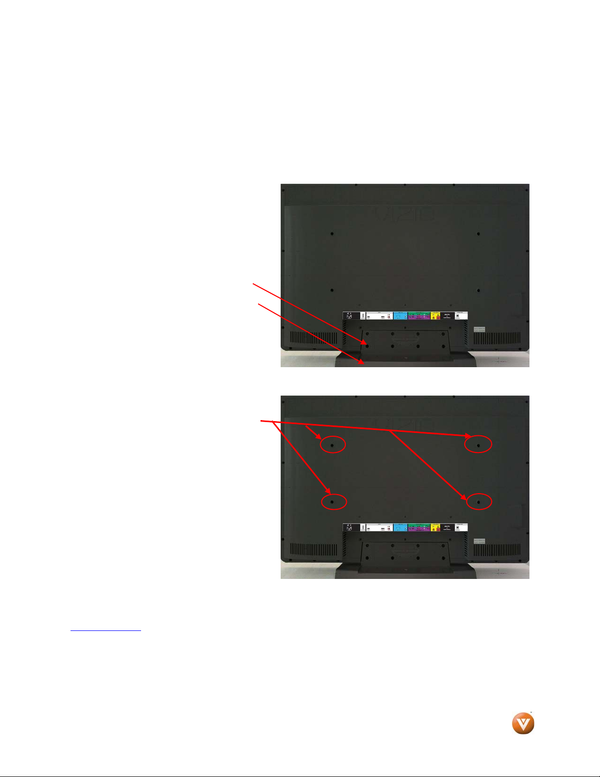
Preparing Your LCD HDTV for Wall Mounting
The VIZIO VW32L HDTV40A can either be kept on the stand base or mounted on the wall for viewing. If
you choose to mount the VW32L HDTV40A on the wall, please follow the instructions below for removing
the stand base.
To remove the stand base
1. Unplug all of the cables and cords
from your VIZIO VW32L HDTV40A.
2. Place the VW32L HDTV40A face
down on a soft and flat surface
(blanket, foam, cloth, etc) to prevent
any damage to the TV.
3. Remove the eight (8) screws holding
the base to the VW32L HDTV40A.
4. Carefully remove the stand base.
Now, the VW32L HDTV40A can fit securely to
a mount (sold separately) by utilizing the
mounting holes in the center of the back panel
of the High Definition TV. Please make sure to
read the instructions of your specific mount to
properly hang the VW32L HDTV40A.
The pitch of the mounting holes is 420mm
horizontally and 200mm vertically.
The screw type required is metric M8, 1.25mm
pitch. The length of the screws will depend on
the thickness plate being attach to the TV set,
our brackets come with different length
screws.
To find the perfect mount for the VIZIO VW32L HDTV40A, browse VIZIO’s certified mount selection at
www.VIZIO.com
or call directly 888-VIZIOCE (888-849-4623).
Version 10/17/2008 6
www.VIZIO.com
Page 7

VIZIO® VW32L HDTV40A User Manual
Table of Contents
Chapter 1 Basic Controls and Connections .................................................................. 9
1.1 Front Panel .......................................................................................................................................................... 9
1.2 Right Side Panel Controls ................................................................................................................................... 9
1.3 Rear Panel Connections ................................................................................................................................... 10
1.4 VIZIO Remote Control ....................................................................................................................................... 11
1.4.1 Insertion of Batteries in the Remote Control .............................................................................................. 12
1.4.2 Remote Control Range .............................................................................................................................. 12
1.4.3 VIZIO Remote Control Precautions ........................................................................................................... 12
Chapter 2 Connecting Equipment .................................................................................. 13
2.1 Which Video Connection Should I Use? ............................................................................................................ 13
2.2 Connecting Coaxial (RF) ................................................................................................................................... 14
2.2.1 Using Your Antenna or Digital Cable for DTV /TV ..................................................................................... 14
2.2.2 Using the Antenna or Cable through your VCR ......................................................................................... 14
2.3 Connecting Your HDTV Set-Top Box ................................................................................................................ 15
2.3.1 Using HDMI ............................................................................................................................................... 15
2.3.2 Using Component Video ............................................................................................................................ 17
2.4 Connecting Your Basic Set-Top Box ................................................................................................................. 18
2.4.1 Using Composite Video ............................................................................................................................. 18
2.4.2 Using Coax (RF) ........................................................................................................................................ 18
2.5 Connecting Your DVD Player ............................................................................................................................ 19
2.5.1 Using HDMI ............................................................................................................................................... 19
2.5.2 For DVD Players with DVI: ........................................................................................................................ 20
2.5.3 Using Component Video ............................................................................................................................ 21
2.5.4 Using S-Video (AV) .................................................................................................................................... 22
2.5.5 Using Composite (AV) Video ..................................................................................................................... 22
2.6 Connecting Your VCR or Video Camera ........................................................................................................... 23
2.7 Connecting an external Receiver/Amp .............................................................................................................. 24
2.7.1 Optical Output of Audio received with HD Programs ................................................................................. 24
2.8 Connecting a PC Computer .............................................................................................................................. 25
2.8.1 Preset PC Resolutions ............................................................................................................................... 26
2.9 Setting Up to Watch Television ......................................................................................................................... 27
2.10 Basic LCD HDTV Start Up .............................................................................................................................. 27
2.11 Watching a TV Program .................................................................................................................................. 33
2.12 Adjusting Basic HDTV Settings ....................................................................................................................... 34
2.13 Program Information ........................................................................................................................................ 34
Chapter 3 Advanced Adjustment of HDTV ................................................................... 35
3.1 Using the On Screen Display (OSD) ................................................................................................................. 35
3.2 DTV / TV Input Picture Adjustment .................................................................................................................... 36
3.2.1 Picture Mode ............................................................................................................................................. 36
3.2.2 Backlight .................................................................................................................................................... 37
3.2.3 Brightness .................................................................................................................................................. 37
3.2.4 Contrast ..................................................................................................................................................... 38
3.2.5 Color .......................................................................................................................................................... 38
3.2.6 Tint ............................................................................................................................................................. 38
3.2.7 Sharpness ................................................................................................................................................. 39
3.2.8 Color Temperature..................................................................................................................................... 39
3.2.9 Advanced Video ........................................................................................................................................ 40
3.3 DTV / TV Input Audio Adjustment...................................................................................................................... 42
3.3.1 Volume ...................................................................................................................................................... 42
3.3.2 Bass ........................................................................................................................................................... 42
3.3.3 Treble ........................................................................................................................................................ 43
3.3.4 Balance ...................................................................................................................................................... 43
3.3.5 Surround .................................................................................................................................................... 43
3.3.6 Digital Audio Out ........................................................................................................................................ 44
3.3.7 Speakers ................................................................................................................................................... 44
3.3.8 Lip Sync ..................................................................................................................................................... 44
3.4 DTV / TV Tuner Setup ....................................................................................................................................... 45
3.4.1 Tuner Mode ............................................................................................................................................... 45
Version 10/17/2008 7
www.VIZIO.com
Page 8

VIZIO® VW32L HDTV40A User Manual
3.4.2 Auto Search ............................................................................................................................................... 45
3.4.3 Skip Channel ............................................................................................................................................. 45
3.4.4 MTS ........................................................................................................................................................... 46
3.4.5 Time Zone ................................................................................................................................................. 46
3.4.6 Daylight Saving .......................................................................................................................................... 46
3.5 DTV / TV Input Setup ........................................................................................................................................ 47
3.5.1 Language ................................................................................................................................................... 47
3.5.2 Sleep Timer ............................................................................................................................................... 47
3.5.3 Wide .......................................................................................................................................................... 47
3.5.4 Input Naming ............................................................................................................................................. 48
3.5.5 Closed Caption (CC) .................................................................................................................................. 49
3.5.6 Digital Closed Caption Style (Digital CC Style) .......................................................................................... 49
3.5.7 System Reset ............................................................................................................................................ 50
DTV / TV Input Parental Control .............................................................................................................................. 51
3.5.8 Channel Block ........................................................................................................................................... 51
3.5.9 US TV Rating ............................................................................................................................................. 52
3.5.10 US Movie Rating (For US) ....................................................................................................................... 53
3.5.11 Canadian English Rating ......................................................................................................................... 53
3.5.12 Canadian French Rating .......................................................................................................................... 54
3.5.13 DTV Rating .............................................................................................................................................. 54
3.5.14 Blocked Unrated Programming ................................................................................................................ 55
3.5.15 Change the Password ............................................................................................................................. 55
3.6 HDMI Input Picture Adjustment ......................................................................................................................... 56
3.7 HDMI Input Audio Adjustment ........................................................................................................................... 56
3.8 HDMI Input Setup .............................................................................................................................................. 56
3.9 Video Input Picture Adjustment ......................................................................................................................... 57
3.10 Video Input Audio Adjustment ......................................................................................................................... 57
3.11 Video Input Setup ............................................................................................................................................ 58
3.12 Video Input Parental Control ........................................................................................................................... 58
3.13 PC Input Picture Adjustment ........................................................................................................................... 59
3.13.1 Auto Adjust .............................................................................................................................................. 59
3.13.2 Backlight .................................................................................................................................................. 59
3.13.3 Brightness ................................................................................................................................................ 60
3.13.4 Contrast ................................................................................................................................................... 60
3.13.5 Color Temperature ................................................................................................................................... 61
3.13.6 H-SIZE ..................................................................................................................................................... 61
3.13.7 H-Position ................................................................................................................................................ 61
3.13.8 V. Position ............................................................................................................................................... 62
3.13.9 Fine Tune ................................................................................................................................................ 62
3.14 PC Input Audio Adjustment ............................................................................................................................. 62
3.15 PC Input Setup ................................................................................................................................................ 62
3.16 Understanding Viewing Features .................................................................................................................... 63
3.16.1 Viewing Modes ........................................................................................................................................ 63
3.17 Using a Cable or Satellite Remote .................................................................................................................. 64
Chapter 4 Maintenance and Troubleshooting ............................................................. 64
4.1 Maintenance ...................................................................................................................................................... 64
4.2 TV and Stand Base Assembly ........................................................................................................................... 65
4.3 Troubleshooting Guide ...................................................................................................................................... 66
4.4 Telephone & Technical Support ........................................................................................................................ 67
4.5 Compliance ....................................................................................................................................................... 68
4.6 FCC Class B Radio Interference Statement ...................................................................................................... 68
Chapter 5 Miscellaneous Information ........................................................................... 69
5.1 Specifications .................................................................................................................................................... 69
5.2 Glossary – Standard Definitions ........................................................................................................................ 70
5.3 Index ................................................................................................................................................................. 71
Version 10/17/2008 8
www.VIZIO.com
Page 9
VIZIO® VW32L HDTV40A User Manual
Chapter 1 Basic Controls and Connections
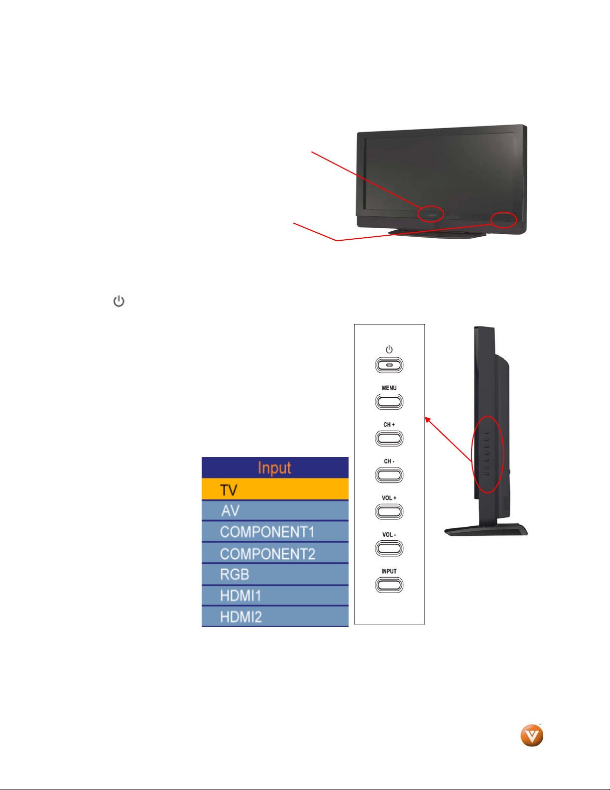
1.1 Front Panel
Power ‘VIZIO’ light – The VIZIO name lights white when
powered on and orange when powered off.
Remote Control Sensor – This is the window through which
all of the remote control signals pass to the sensor. Point the
remote control directly at this window for the best response to
the remote signal.
1.2 Right Side Panel Controls
Power ( ) – Switch the VW32L HDTV40A on by pressing the button once. Press the button again to
the VW32L HDTV40A off.
Menu – This button activates the On Screen Display (OSD).
Pressing it a second time will select the first option or feature
of the OSD. If an option or feature which requires the display
of the slide bar is selected, pressing this button will toggle
between displaying the slide bar and the last OSD menu.
Channel +/- – Use these buttons to step up or down the TV
channels. While the OSD is active, these buttons function as
up and down controls in the OSD menus.
Volume +/- – Use these buttons to increase or decrease to
the speaker volume. While the OSD is active, these buttons
function as left and right controls in the OSD menus.
Input – Repeated pressing
of this buttons steps
through the input sources
in the following sequence:
TV, AV (S-VIDEO),
COMP1, COMP2, RGB,
HDMI1 and HDMI2. Once
you have stepped through
the entire sequence, you
will return to the beginning.
When the OSD is on, if a
sub-menu is active,
pressing this button will
return to the previous
menu level.
Version 10/17/2008 9
www.VIZIO.com
Page 10
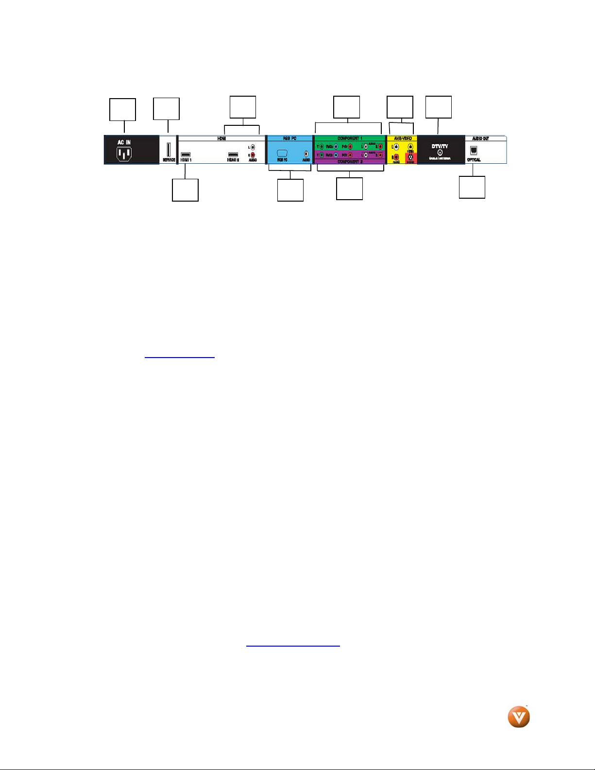
1.3 Rear Panel Connections
VIZIO® VW32L HDTV40A User Manual
1. AC IN – Plug-in the supplied AC Power Cord here.
2. SERVICE – This custom communication port is for factory service only. Use of this input for
3. HDMI 1 – Connect the primary source for digital video such as a DVD multimedia player or
4. HDMI 2 – Connect the secondary source for digital video such as a DVD multimedia player or
5. RGB PC – Connect the video and audio from a computer here. The blue color band on the
6. COMPONENT 1 (YPb/CbPr/Cr with Audio L/R) – Connect the primary source for
7. COMPONENT 2 (YPb/CbPr/Cr with Audio L/R) – Connect the secondary source for
8. AV/S-VIDEO – Connect the source for composite video devices, such as a VCR or video
9. DTV/TV – Connect to an antenna or digital cable (no Cable Box) for Digital TV.*
10. OPTICAL DIGITAL AUDIO OUT – When a digital audio signal is associated with an input
* For digital TV stations in your area visit www.antennaweb.org
1
any purpose other than factory authorized service will void the manufacturer’s
warranty of this equipment.
set top box through this all digital connector. The white color band on the rear of the High
Definition TV indicates this connection.
set top box through this all digital connector. The white color band on the rear of the High
Definition TV indicates this connection. For users who want to connect to a DVI enabled
device, use a DVI-HDMI cable and connect the Analog Audio output of the device to the L+R
AUDIO here. Your VIZIO Certified HDMI and HDMI-DVI cables are available for purchase
from www.VIZIO.com
rear of the High Definition TV indicates this connection. A 1/8” plug stereo cable is needed to
connect the audio out from the computer to the 1/8” jack connector in the rear of the High
Definition TV.
component video devices such as a DVD Player or set top box here. From left to right, use
green for Y, blue for Pb (or Cb), red for Pr (or Cr), white for left audio and red for right audio
inputs. The green color band on the rear of the High Definition TV indicates this connection.
component video devices such as a DVD Player or set top box here. From left to right, use
green for Y, blue for Pb (or Cb), red for Pr (or Cr), white for left audio and red for right audio
inputs. The purple color band on the rear of the High Definition TV indicates this connection.
game. Use the white and red connectors to connect the external audio from the same source.
This connection is on rear side of the High Definition TV. The signal being carried by the SVideo cable and connector; if connected, will take priority over the video (yellow connector)
RCA connector. Keep in mind that if audio is needed then left (white connector) and right (red
connector) must be connected to the signal source using the RCA audio patch cables.
which is selected for viewing, the digital audio associated with digital programming will be
available on this SPDIF Optical connector for connection to your home theatre system. The
white color band on the rear of the TV indicates this connection.
2
3
4
5
or by calling 888-VIZIOCE (888-849-4623).
6
7
.
8 9
10
Version 10/17/2008 10
www.VIZIO.com
Page 11
VIZIO® VW32L HDTV40A User Manual
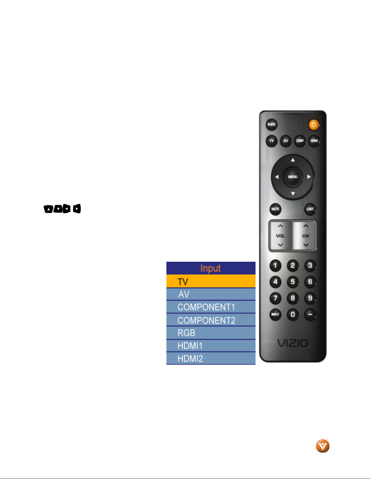
1.4 VIZIO Remote Control
GUIDE – This button displays program information. Press this button once and the information of the
program being viewed is shown.
POWER – Press this button to turn the TV on from the Standby mode. Press it again to return to the
Standby mode.
TV – Press this button to select TV.
AV – Press this button to select the Audio Video input. Pressing this button
repeatedly will get you to the AV input. Keep in mind that if S-Video cable is
being used, then AV will show the signal going through this input as the Svideo takes priority.
COMPONENT – Press this button to select the Component (YPbPr) input.
Pressing this button repeatedly will take you through the Component
(Component 1 and component 2) inputs.
HDMI – Press this button to select the HDMI input. Pressing this button
repeatedly will get you through the HDMI (HDMI1, and HDMI 2) different
inputs
MENU – Use this button for the On-Screen Display (OSD) menus. When use
within the OSD menus, pressing this key will make the selection of an option.
- These buttons navigate the On-Screen Display (OSD).
MUTE – This button turns the sound on and off.
LAST – This button recalls the previously viewed channel when it is used in
TV mode; meaning that the TV unit has control over the signal or program
being watched. This button also has different functions when being used in
conjunction with the On-Screen Display (OSD) menu.
VOL (+ or -) – These buttons turn the volume up or down.
CH (+ or -) – These buttons change the
channels up or down.
Number Button Pad – Use these buttons
to select a channel or enter a password.
INPUT – This button allows the user to
cycle through the inputs. Repeatedly
pressing of this button will step you through
the input sources in the following
sequence: TV, AV (S-Video), COMP1,
COMP2, RGB, HDMI1 and HDMI2. Once
you have stepped through the entire
sequence, you will return to the beginning.
- (DASH) – When selecting a digital
channel directly, use this button for the
separation of main and sub-channels. For example, channel 28-2 would be selected by the button
sequence 2 8 --2.
Version 10/17/2008 11
www.VIZIO.com
Page 12
VIZIO® VW32L HDTV40A User Manual
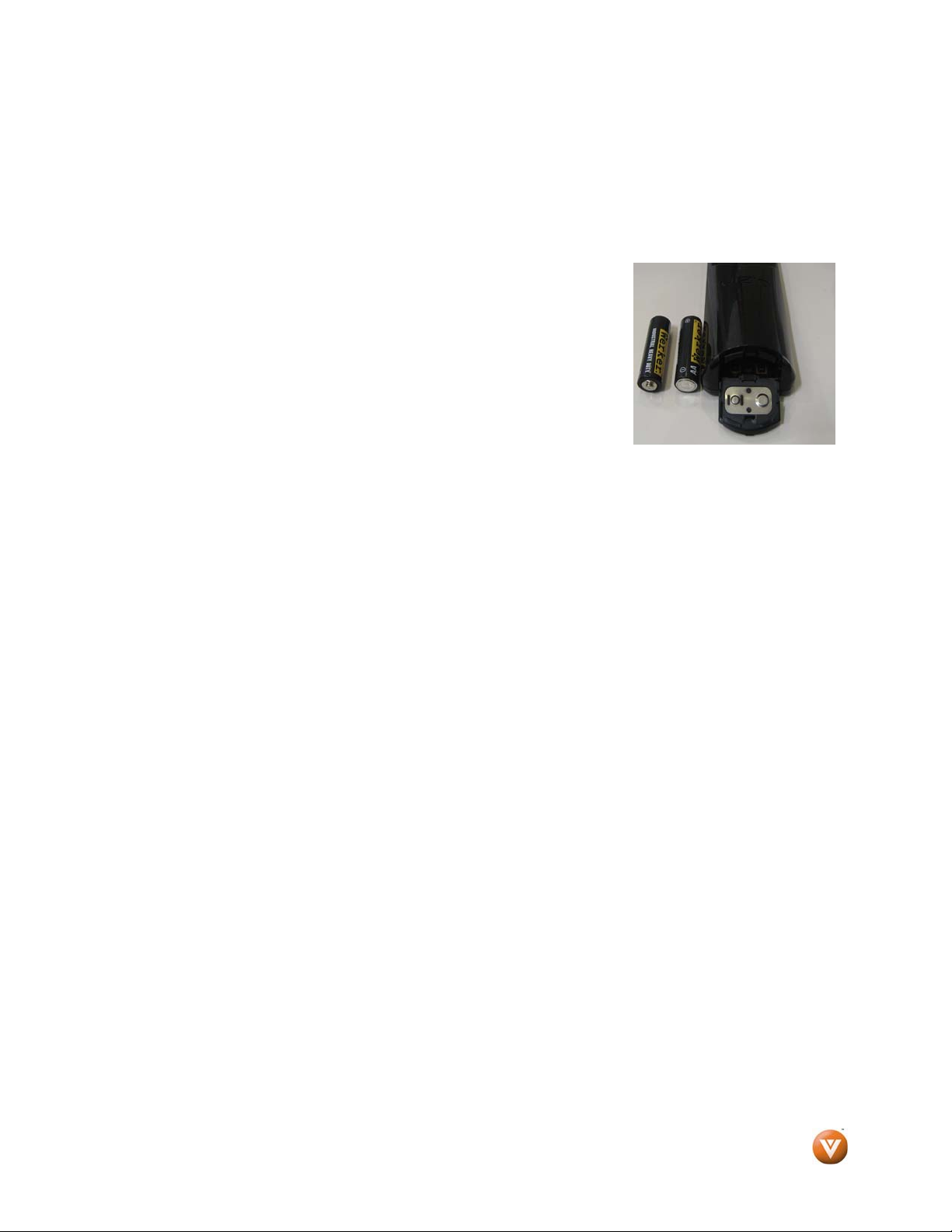
1.4.1 Insertion of Batteries in the Remote Control
Press and slide out the battery cover by following the direction shown by the molded arrow on the surface
of the cover.
Insert two AA batteries into the remote control. Make sure that you match the (+) and (-) symbols on the
batteries with the (+) and (-) symbols inside the battery compartment.
Press and slide the battery cover back into place.
Precautionary Tips for Inserting the Batteries:
Only use the specified AA batteries.
Do not mix new and old batteries. This may result in cracking or leakage
that may pose a fire risk or lead to personal injury.
Inserting the batteries incorrectly may also result in cracking or leakage
that may pose a fire risk or lead to personal injury.
Dispose of the batteries in accordance with local laws and regulations.
Keep the batteries away from children and pets.
1.4.2 Remote Control Range
Point the remote control at the remote control sensor to transmit the commands.
Do not place any obstacles between the remote control and the receiver window.
The effective range of the remote control is approximately 30 feet (10 meters) from the front of the
receiver window, 30° to the left and right, 20° up and down.
1.4.3 VIZIO Remote Control Precautions
The remote control should be kept dry and away from heat sources. Avoid humidity.
If the TV responds erratically to the remote control or does not respond at all, check the batteries. If the
batteries are low or exhausted, replace them with fresh batteries.
When not using the remote control for a long period of time, remove the batteries.
Do not take the batteries apart, heat them, or throw them into a fire.
Do not subject the remote control to undue physical stress, such as striking or dropping it.
Do not attempt to clean the remote control with a volatile solvent. Wipe it with a clean, damp cloth.
Version 10/17/2008 12
www.VIZIO.com
Page 13
VIZIO® VW32L HDTV40A User Manual
Chapter 2 Connecting Equipment
2.1 Which Video Connection Should I Use?
The VIZIO VW32L HDTV40A has six different ways to connect your video equipment from a basic
connection to the most advanced for digital displays.
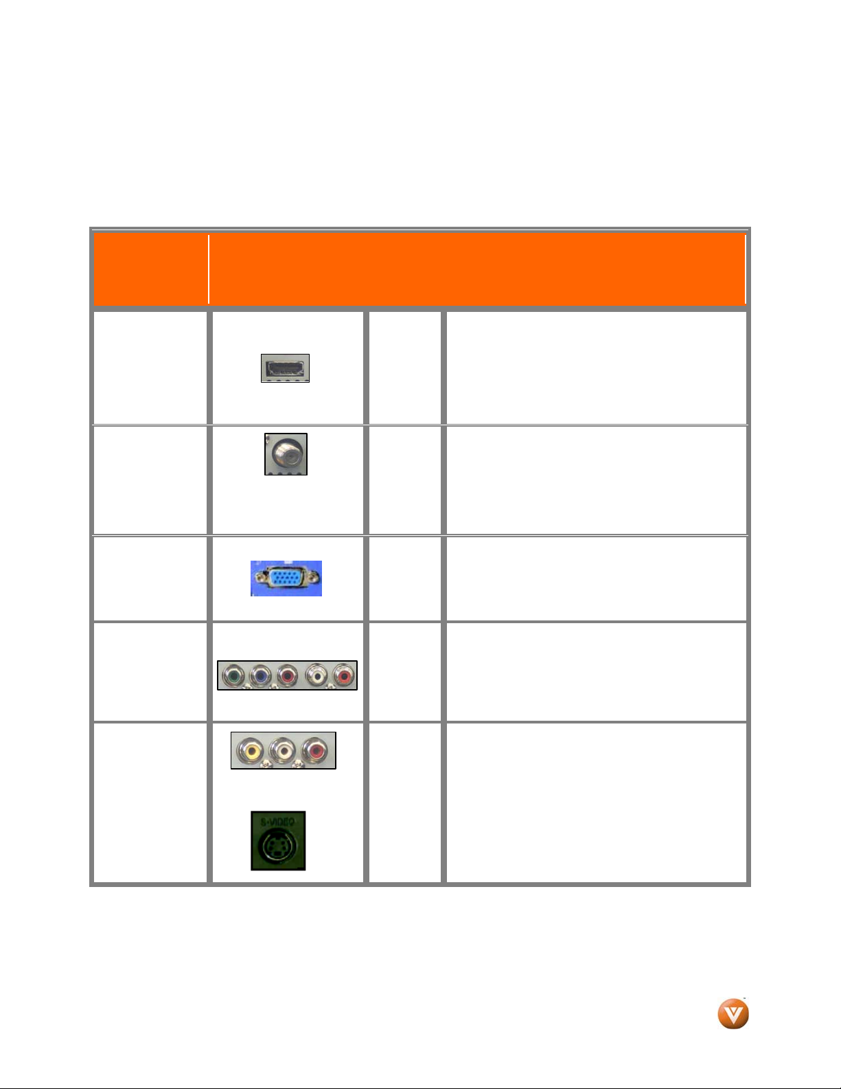
Rear
Connection
Quality (type)
Connector
Panel
Color
Codes
Description
Best
(digital)
Best
(digital)
- - - - - - - - - - - Good
(analog)
Best
(analog)
Better
(analog)
White
Black
Blue
Green
and
Purple
HDMI (High-Definition Multimedia Interface) - It is the
first and only industry-supported, uncompressed, alldigital audio/video interface. HDMI provides an
interface between any audio/video source, such as a
set-top box, DVD player, or A/V receiver and an
audio and/or video monitor, such as a digital
television (DTV), over a single cable.
DTV Coaxial RF. When used for MPEG2 encoded
bit streams from ATSC broadcast programming, this
input takes advantage of the High Definition content.
- - - - - - - - - - - - - - - - - - - - - - - - - - - - - - - - - - - - - TV Coaxial RF. This is the connection for standard
NTSC TV using antenna or cable.
RGB PC (VGA) – This video input has separate red,
green and blue color components. The signal
carries horizontal and vertical sync information on
the green signal. This is most commonly used for
PC input.
Component - The video signal is separated into
three signals, one containing the black-and-white
information and the other two containing the color
information. This enhancement over S-Video takes
advantage of the superior picture provided by
progressive scan DVD players and HDTV formats.
Composite (AV) - The complete video signal is
carried through this single (yellow) pin connector.
This is the most commonly used video connection.
S-Video (AV) - The video signal is separated into two
signals, one containing the black-and-white
information and the other containing the color
information. Separating the color in this way avoids
‘cross color’ effects where closely spaced black and
white lines are erroneously displayed in color. It also
enables text to be displayed more sharply.
Good
(analog)
Yellow
and
Red
Note: For more info refer to the Quick Start Guide
Version 10/17/2008 13
www.VIZIO.com
Page 14
VIZIO® VW32L HDTV40A User Manual
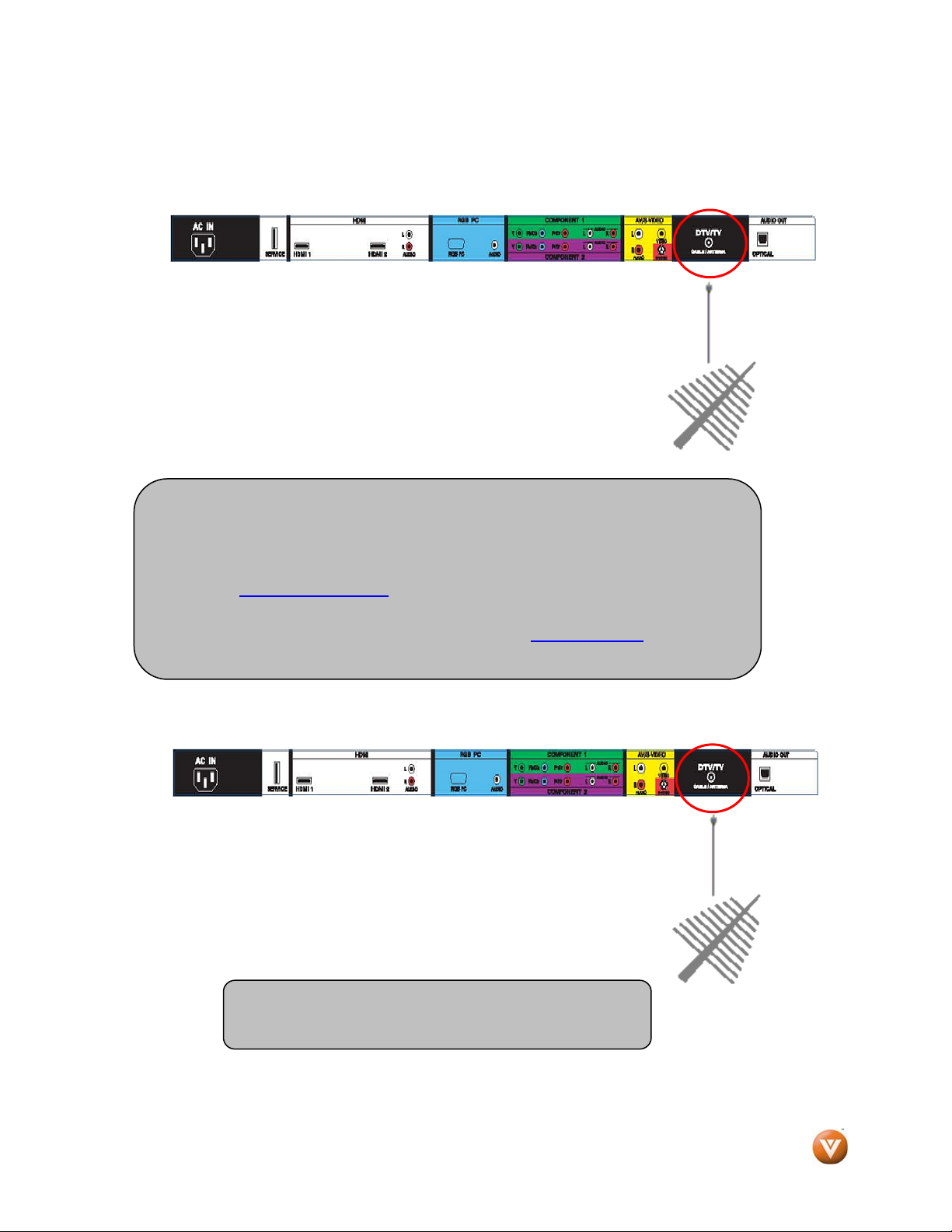
2.2 Connecting Coaxial (RF)
2.2.1 Using Your Antenna or Digital Cable for DTV /TV
1. Turn off the power to the HDTV.
2. Connect the coaxial (RF) connector from your antenna or digital
cable (out-of-the-wall, not from the Cable Box) to the DTV/TV
CABLE/ANTENNA connector.
3. Turn on the power to the HDTV.
4. Select DTV using the INPUT button on the remote or side of the
High Definition TV, or directly by pressing the TV button on the
Remote Control.
Note:
a) Not all digital TV broadcasts are High Definition (HD). Refer to the
program guides, or consult your cable, satellite or TV station operator.
b) Digital broadcasts are not available in all areas. Refer to
www.antennaweb.org
c) Make sure the antenna and coaxial cable are correctly grounded.
d) For Professional installation contact us at www.VIZIO.com
VIZIOCE (1-888-849-4623).
for detailed information.
or call 1-888-
2.2.2 Using the Antenna or Cable through your VCR
1. Turn off the power to the HDTV and VCR.
2. Connect the “Output to TV”, “RF Out” or “Antenna Out” connector
on the rear of your VCR to the DTV/TV CABLE/ANTENNA
connector at the rear of the High Definition TV.
3. Turn on the power to the HDTV and VCR.
4. Select TV using the INPUT button on the remote or side of the
High Definition TV, or directly by pressing the TV button on the
Remote Control.
Version 10/17/2008 14
Note: If you have an off-air antenna or cable TV, connect
it to the “Antenna In” connector on the rear of your VCR.
www.VIZIO.com
Page 15
VIZIO® VW32L HDTV40A User Manual
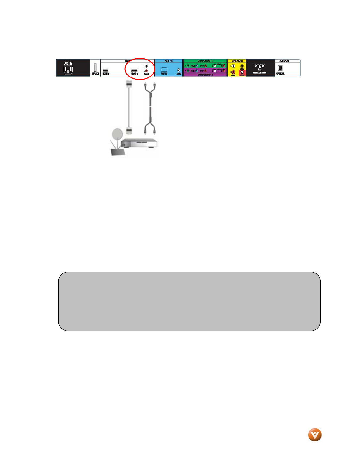
2.3 Connecting Your HDTV Set-Top Box
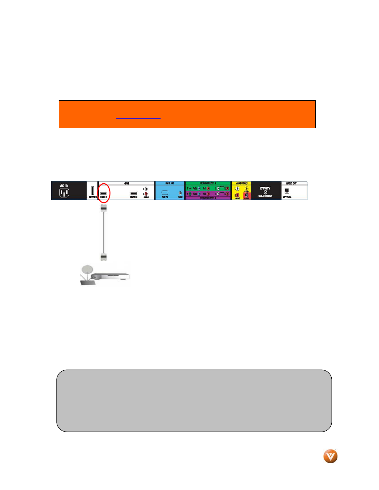
2.3.1 Using HDMI
HDTV Set-Top Boxes that have a HDMI digital interface should be connected to the HDMI input of the
LCD HDTV for optimal results.
Connecting your HDTV Set-Top Box (Best):
Note: To maintain the display quality, use a VIZIO certified HDMI. Length is available up
to 10 meters. See www.VIZIO.com
1. Turn off the power to the HDTV and HDTV Set-Top Box.
2. Connect a HDMI cable to the HDMI output of your HDTV Set-Top Box and the other end to
the HDMI Input (white color area) at the rear of the High Definition TV.
3. Turn on the power to the HDTV and HDTV Set-Top Box.
4. Select HDMI 1 using the INPUT button on the remote or side of the High Definition TV, or
directly by pressing the HDMI button on the Remote Control.
5. If HDMI 1 is being used, used HDMI 2 as the input and follow steps 1 through 3; and then
select HDMI 2 in step 4.
Note:
a) The HDMI input on the HDTV supports High-bandwidth Digital Content Protection
(HDCP). HDCP encrypts the transmission between the video source and the
digital display for added security and protection.
b) Refer to your HDTV Set-Top Box user manual for more information about the
video output requirements of the product or consult your cable or satellite operator.
or call 1-888-VIZIOCE (1-888-849-4623) for details.
Version 10/17/2008 15
www.VIZIO.com
Page 16
VIZIO® VW32L HDTV40A User Manual
For HDTV Set-Top Boxes with DVI:
1. Turn off the power to the HDTV and HDTV Set-Top Box.
2. Using a HDMI-DVI cable, connect the DVI end to your HDTV Set-Top Box and the HDMI end
to the HDMI Input (white color area) at the rear of the High Definition TV.
3. Using an audio cable (white and red connectors), connect the cable to the audio output
connectors associated with the DVI output on your HDTV Set-Top Box and connect the other
end to the audio connectors associated with the HDMI input (white area) at the rear of the
High Definition TV.
4. Turn on the power to the HDTV and HDTV Set-Top Box.
5. Select HDMI using the INPUT button on the remote or side of the High Definition TV, or
directly by pressing the HDMI button on the Remote Control.
Note: The HDMI Input is for HD Video and using HDMI-DVI will only support 640x480 at 60Hz from a PC.
Use the RGB PC input for a greater selection of PC formats.
Note:
a) The HDMI input on the HDTV supports High-bandwidth Digital Content Protection
(HDCP). HDCP encrypts the transmission between the video source and the
digital display for added security and protection.
b) Refer to your HDTV Set-Top Box user manual for more information about the
video output requirements of the product or consult your cable or satellite operator.
Version 10/17/2008 16
www.VIZIO.com
Page 17
VIZIO® VW32L HDTV40A User Manual
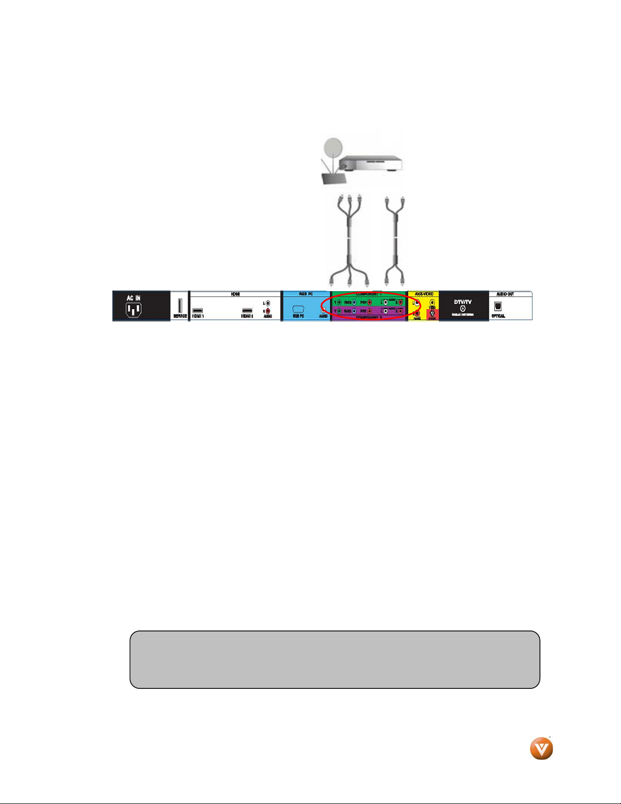
2.3.2 Using Component Video
Connecting your HDTV Set-Top Box (Better):
1. Turn off the power to the HDTV and HDTV Set-Top Box.
2. Connect the Y (green color) connector on your HDTV Set-Top Box to the corresponding Y
(green color) connector in the Component 1 group (green color area - row of connectors
nearest to you when viewing from the rear of the High Definition TV) at the rear of the High
Definition TV.
3. Connect the Pb (blue color) connector on your HDTV Set-Top Box to the corresponding Pb
(blue color) connector in the Component 1 group (green color area - row of connectors
nearest to you when viewing from the rear of the High Definition TV) at the rear of the High
Definition TV.
4. Connect the Pr (red color) connector on your HDTV Set-Top Box to the corresponding Pr (red
color) connector in the Component 1 group (green color area - row of connectors nearest to
you when viewing from the rear of the High Definition TV) at the rear of the High Definition
TV.
5. Using an audio cable (white and red connectors), connect the cable to the audio output
connectors associated with the Component output on your HDTV Set-Top Box and connect
the other end to the audio connectors associated with the Component 1 input (green color
area) at the rear of the High Definition TV.
6. Turn on the power to the HDTV and HDTV Set-Top Box.
7. Select Component 1 using the INPUT button on the remote or side of the High Definition TV,
or directly by pressing the Component button on the Remote Control.
8. If Component 1 input is being used, use Component 2 as the input and follow the steps 1
through 6; and then select Component 2 in step 7.
Note:
Refer to your HDTV Set-Top Box user manual for more information about the
video output requirements of the product or consult your cable or satellite operator.
Version 10/17/2008 17
www.VIZIO.com
Page 18
VIZIO® VW32L HDTV40A User Manual
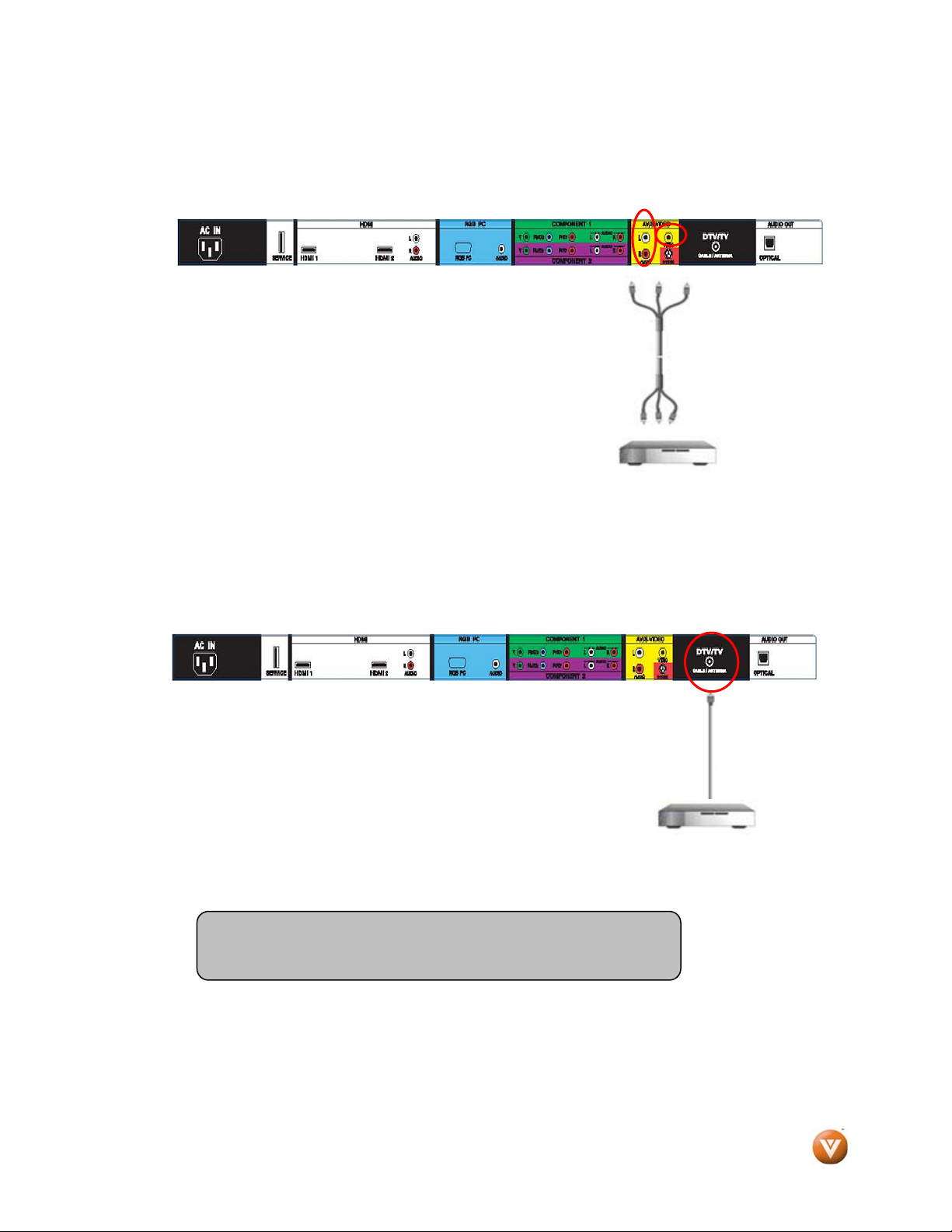
2.4 Connecting Your Basic Set-Top Box
2.4.1 Using Composite Video
1. Turn off the power to the HDTV and Set-Top Box.
2. Using the AV Cable, connect the Video (yellow color)
connector on your Set-Top Box to the corresponding Video
(yellow color) connector in the AV group (yellow color area)
at the rear of the High Definition TV.
3. Using the white and red connectors, connect the cable to
the audio output connectors associated with the Video
output on your Set-Top Box and connect the other end to
the audio connectors associated with the AV input (yellow
color area) at the rear of the High Definition TV.
4. Turn on the power to the TV and Set-Top Box.
5. Select AV using the INPUT button on the remote or side of the High Definition TV, or directly
by pressing the AV button on the Remote Control.
2.4.2 Using Coax (RF)
1. Turn off the power to the HDTV and Set-Top Box.
2. Using a Coax (RF) cable, connect one end to the TV OUT (RF) on your
Set Top Box and the other end to the DTV/TV input at the rear of the
High Definition TV.
3. Turn on the power to the HDTV and Set-Top Box.
4. Select TV using the INPUT button on the remote or side of the
High Definition TV, or directly by pressing the TV button (below
the GUIDE button) on the Remote Control.
Note: Refer to your Set Top Box user manual for more information
about selecting the video or RF output of the product.
Version 10/17/2008 18
www.VIZIO.com
Page 19
VIZIO® VW32L HDTV40A User Manual
2.5 Connecting Your DVD Player
You have several options for connecting your DVD player to your VIZIO VW32L HDTV40A; HDMI,
Component, AV (S-Video or Composite) inputs. Based on your configuration, you can decide which
option is right for you.
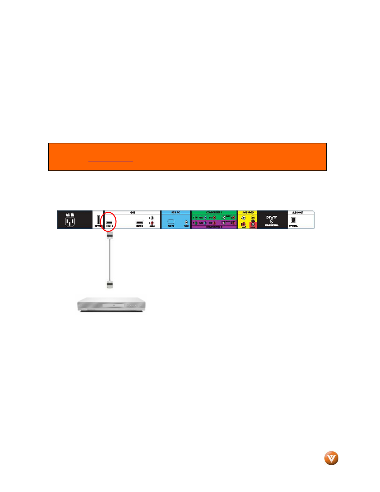
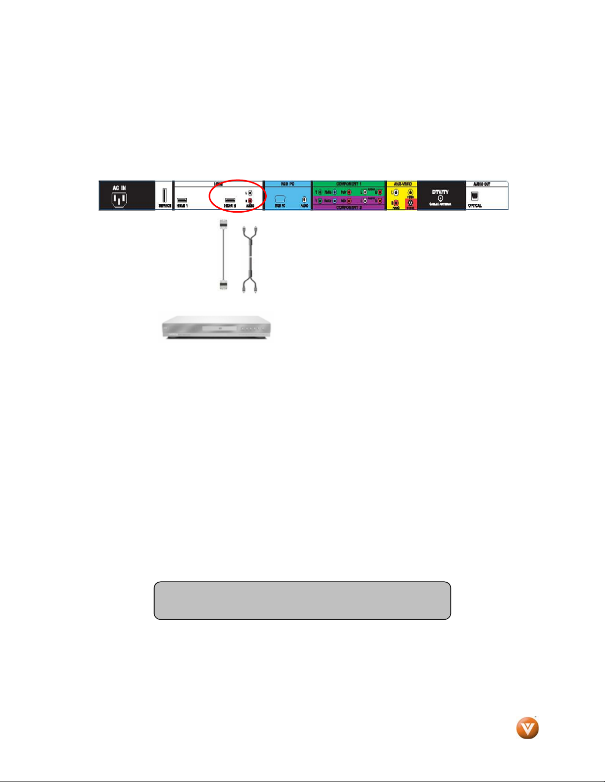
2.5.1 Using HDMI
DVD players that have a digital interface such as HDMI (High Definition Multimedia Interface) should be
connected to the HDMI input of the VIZIO VW32L HDTV40A for optimal results.
Note: To maintain the display quality, use a VIZIO certified HDMI. Length is available up to 10
meters. See www.VIZIO.com
Connecting your DVD Player (Best):
or call 1-888-VIZIOCE (1-888-849-4623) for details.
1. Turn off the power to the High Definition TV and DVD player.
2. Connect a HDMI cable to the HDMI output of your DVD player and the other end to the HDMI
Input (white color area) at the rear of the High Definition TV.
3. Turn on the power to the High Definition TV and DVD player.
4. Select HDMI 1 using the INPUT button on the remote or side of the High Definition TV, or
directly by pressing the HDMI button on the Remote Control.
5. If HDMI 1 is being used, connect to HDMI 2 as the input and follow steps 1 through 3; and
then select HDMI 2 in step 4.
Version 10/17/2008 19
www.VIZIO.com
Page 20
VIZIO® VW32L HDTV40A User Manual
2.5.2 For DVD Players with DVI:
1. Turn off the power to the High Definition TV and DVD player.
2. Using a HDMI-DVI cable, connect the DVI end to your DVD player and the HDMI end to the
HDMI Input (white color area) at the rear of the High Definition TV.
3. Connect an audio cable (white and red connectors) to the audio output connectors
associated with the DVI output of the DVD player and connect the other end to the audio
connectors by the HDMI input (white area) at the rear of the High Definition HDTV.
4. Turn on the power to the High Definition TV and your DVD player.
5. Select HDMI 2 using the INPUT button on the remote or side of the High Definition TV, or
directly by pressing the HDMI button on the Remote.
Note: Refer to your DVD player user manual for more
information about the video output requirements of the product.
Version 10/17/2008 20
www.VIZIO.com
Page 21
VIZIO® VW32L HDTV40A User Manual
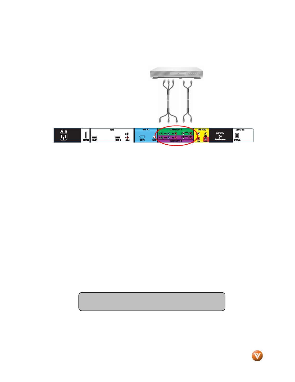
2.5.3 Using Component Video
Connecting your DVD Player (Better):
1. Turn off the power to the High Definition TV and DVD player.
2. Connect the Y (green color) connector on your DVD player to the corresponding Y (green
color) connector in the Component 1 group (green color area - row of connectors nearest to
you when viewing from the rear of the High Definition TV) at the rear of the High Definition TV.
3. Connect the Pb (blue color) connector on your DVD player to the corresponding Pb (blue
color) connector in the Component 1 group (green color area - row of connectors nearest to
you when viewing from the rear of the High Definition TV) at the rear of the High Definition TV.
4. Connect the Pr (red color) connector on your DVD player to the corresponding Pr (red color)
connector in the Component 1 group (green color area - row of connectors nearest to you
when viewing from the rear of the High Definition TV) at the rear of the High Definition TV.
5. Using an audio cable (white and red connectors), connect the cable to the audio output
connectors associated with the Component output on your DVD player and connect the other
end to the audio connectors associated with the Component 1 input (green color area) at the
rear High Definition TV.
6. Turn on the power to the High Definition TV and DVD player.
7. Select Component 1 using the INPUT button on the remote or side High Definition TV, or
directly by pressing the Component button on the Remote Control.
8. If Component 1 input is being used, use Component 2 as the input and follow the steps 1
through 6; and then select Component 2 in step 7.
Note: Refer to your DVD player user manual for more
information about the video output requirements of the product.
Version 10/17/2008 21
www.VIZIO.com
Page 22
VIZIO® VW32L HDTV40A User Manual
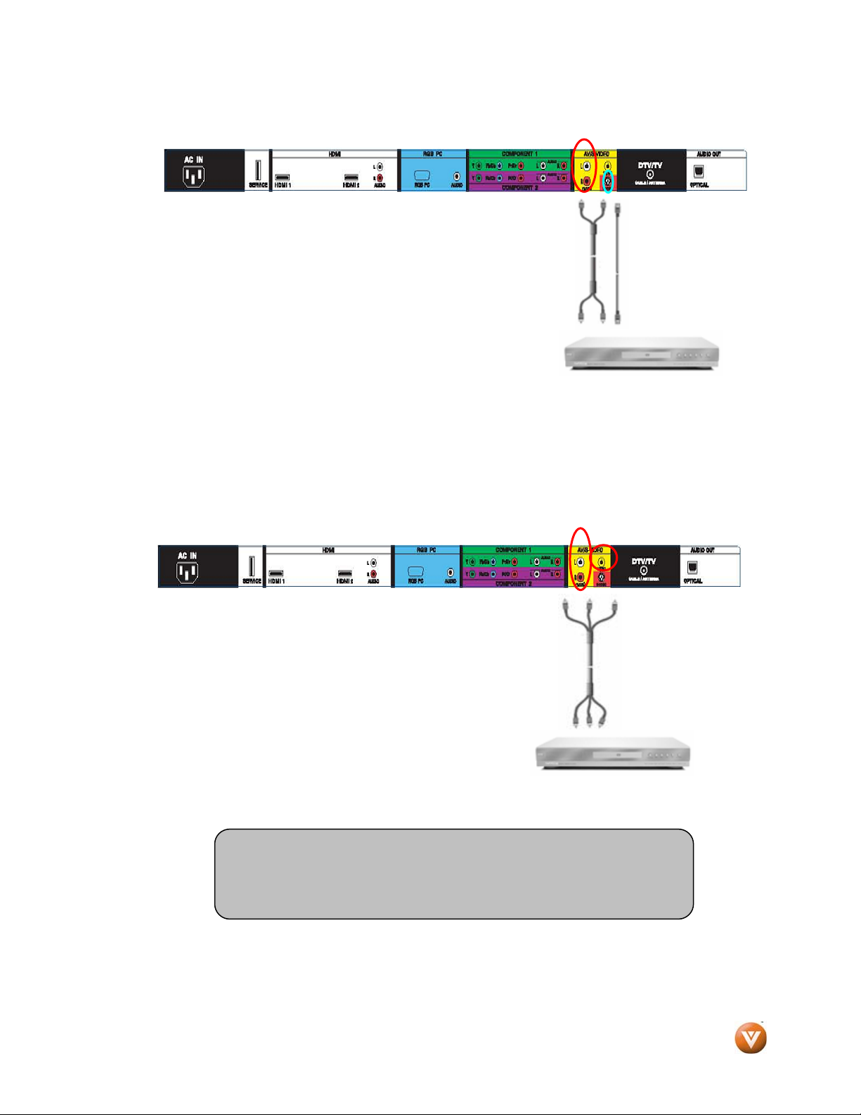
2.5.4 Using S-Video (AV)
Connecting your DVD Player (Good):
1. Turn off the power to the HDTV and DVD player.
2. Connect the S-Video jack on the rear of your DVD player
to the S-Video jack in the AV/S-VIDEO group (yellow/red
color area) on the back High Definition TV.
3. Connect an audio (white and red connector cables) cable
to the audio output connectors associated with the S-Video
output on your DVD player and connect the other end to
the audio connectors associated with the AV/S-VIDEO
input on the back side High Definition TV.
4. Turn on the power to the TV and DVD player.
5. Select AV using the INPUT button on the remote or side High Definition TV, or directly by
pressing the AV button on the Remote Control.
2.5.5 Using Composite (AV) Video
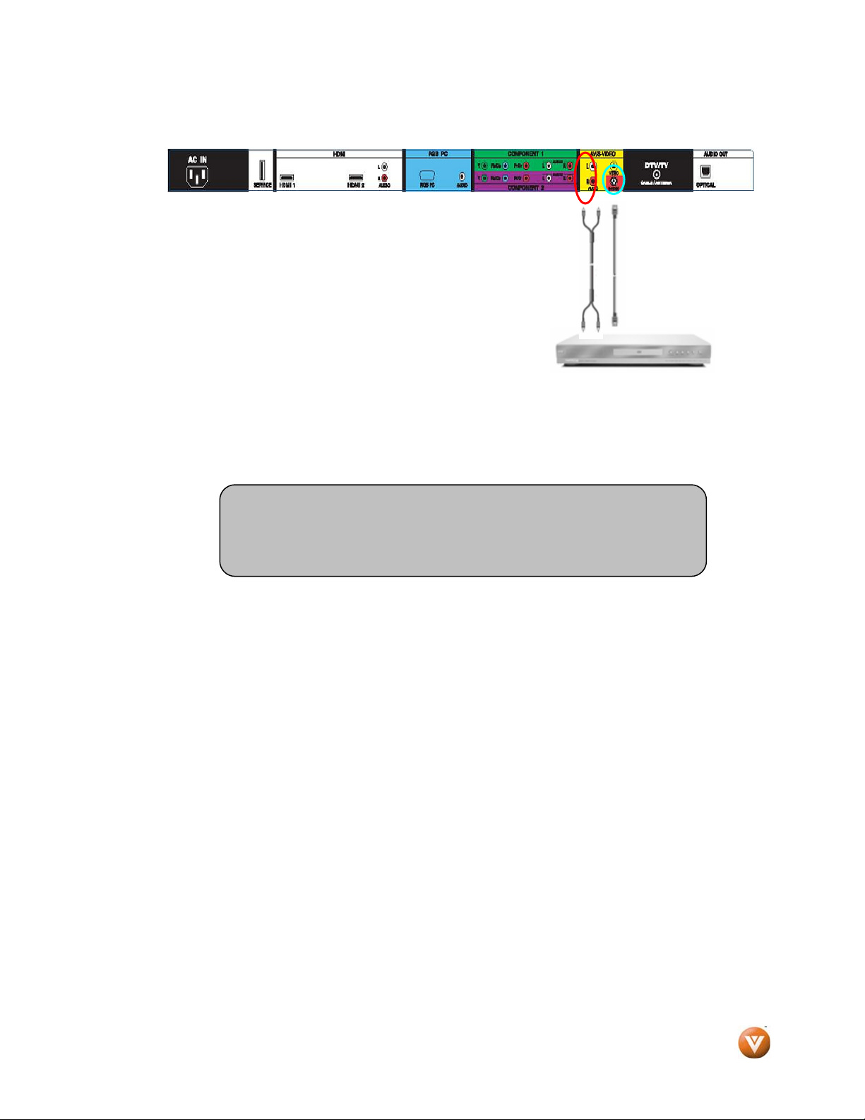
Connecting your DVD Player (Good)
1. Turn off the power to the HDTV and DVD player.
2. Connect the Video (yellow color) connector on your
DVD player to the Video (yellow color) connector in the
AV group (yellow/red color area) at rear of the High
Definition TV.
3. Connect the R (red color) and L (white color) audio
connectors on your DVD player to the corresponding R
(red color) and L (white color) audio input connectors
in the AV group (yellow/red color area).
4. Turn on the power to the TV and DVD Player.
5. Select AV using the INPUT button on the remote or side of the High Definition TV, or directly
by pressing the AV button on the Remote Control.
.
Note:
Refer to your DVD player user manual for more information about
the video output requirements of the product.
Version 10/17/2008 22
www.VIZIO.com
Page 23
VIZIO® VW32L HDTV40A User Manual
2.6 Connecting Your VCR or Video Camera
1. Turn off the HDTV and VCR or Video Camera.
2. Connect the S-Video jack on the rear of your VCR or
Video Camera to the S-Video jack in the AV group on the
rear side of the High Definition TV.
3. Connect an audio (white and red connector cables) cable
to the audio output connectors associated with the SVideo output on your VCR or Video Camera and connect
the other end to the audio connectors associated with
the AV input on the back side of the High Definition
TV.
4. Turn on the power to the HDTV and VCR or Video Camera.
5. Select AV using the INPUT button on the remote or side of the High Definition TV.
Note:
Refer to your VCR or Video Camera user manual for more
information about the video output requirements of the product.
Version 10/17/2008 23
www.VIZIO.com
Page 24

VIZIO® VW32L HDTV40A User Manual
2.7 Connecting an external Receiver/Amp
2.7.1 Optical Output of Audio received with HD
Programs
If your sound system has a SPDIF (optical) digital audio input you can connect it to the optical DIGITAL
AUDIO OUT (white area) at the rear of the LCD HDTV. This is active when receiving audio with the
program being viewed no matter what input is being used.
1. Turn off the power to the LCD HDTV and Receiver/Amp.
2. Using an audio cable (optical cable), connect the cable to the audio input
connector on the Receiver/Amp and connect the other end to the OPTICAL
OUT (white area) audio connector at the rear of the LCD HDTV.
3. Turn on the power to the LCD HDTV and Receiver/Amp.
4. Then press the MENU button on the remote control to open the On-Screen
Display (OSD) menu.
5. Press the on the remote control to
select the Audio menu.
6. Press the on the remote control to
select SPEAKERS.
7. Press the on the remote control to
select OFF so that the sound from the
LCD HDTV will now be routed
through your Receiver/Amp system.
Press the LAST key once to return to the previous
screen or repeatedly to return to your program if
task has been completed.
Note:
a) Refer to your Receiver/Amp user manual to select the corresponding audio input.
b) The audio output can not be connected directly to external speakers.
Version 10/17/2008 24
www.VIZIO.com
Page 25

VIZIO® VW32L HDTV40A User Manual
2.8 Connecting a PC Computer
1. Turn off the power to the High Definition TV and PC Computer.
2. Connect a 15-pin D-Sub RGB (VGA) cable to the RGB output of your pc computer and the
other end to the RGB PC input (blue area) at the rear of the High Definition TV.
3. Connect the Audio Out on your pc computer to the RGB PC Audio (this connection will
require an 1/8” stereo mini plug at the end which goes into the TV) input (blue area) at the
rear of the High Definition TV.
4. Turn on the HDTV and PC Computer.
5. Select RGB using the INPUT button on the remote or side of the High Definition TV.
Note:
a) For the best picture quality when connecting a pc computer through RGB PC, set your pc
computer timing mode to VESA 1366 x 768 at 60Hz. Please refer to the pc or graphic
card’s user guide for additional information on how to set the timing mode and the video
output requirements of the product.
b) A RGB (VGA) cable and stereo mini jack cable are not included and can be purchased at
an electronics store.
Version 10/17/2008 25
www.VIZIO.com
Page 26

VIZIO® VW32L HDTV40A User Manual
2.8.1 Preset PC Resolutions
If connecting to a PC through the RGB PC input, set the TV timing mode to VESA 1366x768 at 60Hz
for best picture quality (refer to the graphic card’s user guide for questions on how to set this timing
mode). Please see the table below for the factory preset resolutions.
Resolution Refresh (Hz) H-Freq (kHz) V-Freq (Hz) H-Sync V-Sync Pixel Freq (MHz)
640x480 60 31.47 59.94 N N 25.18
640x480 75 37.50 75.00 N N 31.50
720x400 70 31.46 70.08 N P 28.32
800x600 60 37.88 60.32 P P 40.00
800x600 72 48.08 72.19 P P 50.00
800x600 75 46.88 75.00 P P 49.50
1024x768 60 48.36 60.00 N N 65.00
1024x768 70 56.48 70.07 N N 75.00
1024x768 75 60.02 75.03 P P 78.75
*1366X768 60 47.55 59.81 P P 85.50
NOTES: N = Negative, P = Positive, * = Primary Mode
Version 10/17/2008 26
www.VIZIO.com
Page 27

VIZIO® VW32L HDTV40A User Manual
2.9 Setting Up to Watch Television
For ‘Preparing Your LCD HDTV for Wall Mounting’, see page 6.
2.10 Basic LCD HDTV Start Up
1. Connecting the Power Cable
Connect the power cord to the power cord connector on the back of the High Definition TV, and
then plug the power cord into an AC wall socket.
2. Connect Audio and Video Cables to the HDTV
(see pages 13 ~ 25 for detailed steps)
3. Turning Power On
Once all the components are connected, press the Power ON button on the side of the High
Definition TV, or press the Power ON (Red) button on the remote control.
4. Initial Setup
After powering on the TV set, the Initial
Setup screen will come up; please press
the button on the remote control.
a. The Language choice screen will
be displayed; the default English
option is highlighted. If you wish
to change the OSD language to
Español or Français, press the
button on the remote control to
select the language you want.
Press the button on the
remote to go to the next screen.
Version 10/17/2008 27
www.VIZIO.com
Page 28

VIZIO® VW32L HDTV40A User Manual
The next screen will display the options to select
between Home Mode and Retail Mode, selecting
Home Mode will give you an opportunity to save
energy.
Press the button on the remote to go to the
next screen.
If Retail Mode is selected by mistake; the next option will allow you to switch your selection back to Home
Mode.
Press the button on the remote to go to the next
screen.
Note: At this point, if a Set-Top Box from your Local Cable or Satellite Service Company or other
equipment is being used; please press the LAST key on the remote control and go to Step 5. If this is not
your case, please continue at Step b.
b. The Tuner screen will be
displayed; default choice is
Antenna. If you are using Cable
(No Box) Service, press the
button on the remote control to
highlight CABLE.
Press the button on the remote
to go to the next screen.
Version 10/17/2008 28
www.VIZIO.com
Page 29

VIZIO® VW32L HDTV40A User Manual
c. The Channel Scan screen will be
displayed; default choice is Scan.
Press the button on the
remote control to commence the
search for available channels to
be stored into memory.
If you do not want to scan for
channels at this time, press the
LAST key on the remote control.
Note: If you select to skip this step by pressing the LAST key, next time that you decide to complete this
procedure; you will need to select the TV as input (through the Input key) and then go through the Menu
option to select the Tuner setup to get the option of scanning the channels again.
d. The screen will now change to
show the progress of the search
for Analog (NTSC) and Digital
(ATSC) channels.
Note: DTV digital broadcast is not available in all areas. Refer to www.antennaweb.org
to get information
about availability in your area, type of antenna and in which direction to point your antenna. The channel
availability through cable depends upon which channels your cable operator supplies in Clear QAM;
consult your cable operator for more information.
Version 10/17/2008 29
www.VIZIO.com
Page 30

VIZIO® VW32L HDTV40A User Manual
e. When finished, the Complete
screen will be displayed to inform
you that the HDTV has completed
the Initial Setup.
Press the button on the
remote control to exit and begin
watching TV.
5. Select Input Source
Select the Input Source for the HDTV by pressing the INPUT
button on the side of the High Definition TV or using the Input button on
the remote control. Pressing this button will cycle you through the
following options: TV, AV (S-VIDEO), Component1, Component2, RGB,
HDMI1 and HDMI2.
Now follow the procedure below to display channels from a
different signal (External TV Tuner, VCR, Cable Box or Satellite
Receiver) source, using different inputs at the back of your TV set.
a. Select the correct input connection; RF (DTV/TV)
connector, Composite (Yellow, Red and White) connectors, Component (Red, Green, Blue plus Red
and White) connectors, HDMI connectors or Separate-Video (S-Video) plus Red and White
connectors (if applicable). Make the physical connection or hook up.
b. If you have an HD service you must use the HDMI (best) or Component connection.
Note: Composite (AV) and S-Video (AV) Cables can only be used for SD (480i) picture s.
c. Turn on your Cable Box, VCR, External TV Tuner or Satellite Receiver and you will see
a picture on your TV set. If there is not picture, make sure you have selected the correct input on the TV
set.
d. If the selected input is RF, you should be aware that the TV set needs to be on either
channel 3 or channel 4 matching the channel which has been selected on the back of the
VCR, Cable Box, External TV Tuner or Satellite Receiver; please refer to Owner or
User’s Manual of such equipment for details.
Version 10/17/2008 30
www.VIZIO.com
Page 31

VIZIO® VW32L HDTV40A User Manual
Note: The TV set will be displaying any television station or program selected by the Cable Box, VCR,
External Tuner or Satellite Receiver. The TV set will not be able to change programs or channels; this is
controlled by the equipment sending the signal. If the service being used is the one which setup
includes a box with two different outputs for two different (distant) rooms, then scanning
channels would help you to find the signal. Be aware that the channel to be selected varies from
provider to provider; meaning that, you may have to call your provider company so they could
provide you the specific channel when using high definition made TV sets. Some examples of
these channels are: 105, 106, 115 and 116.
6. Fine Tuning your TV set for Home Use.
After completing Procedure 4 or
Procedure 5; please follow the steps
below to optimize your TV set display:
a. Press the MENU button to bring up the
Menu display. Use the or button
to scroll to the Color Temperature option.
b. Press the button to select it.
c. Press either or button to change setting
to Normal, and then press the LAST key again to
go back to previous screen.
d. Press either or button to
select the Picture Mode option.
Version 10/17/2008 31
www.VIZIO.com
Page 32

VIZIO® VW32L HDTV40A User Manual
e. Press either or button to change the
Picture Mode option to Standard.
f. Press the LAST key repeatedly to exit the on
screen display Menu.
Note: If Procedure 4 had been done, you would like to do the following to ensure that the correct
program times are shown when pressing the Guide key:
Press the MENU button, this will bring up the
picture mode menu.
Pressing either or button scroll across to
the icon showing the little satellite dish or antenna.
The next screen will appear showing Time Zone.
Using either or button selects it.
Press either or button to choose the proper
Time Zone of your area.
Press the LAST key once to return to the
previous screen or repeatedly to return to your
program if task has been completed.
Your new TV set is now ready to automatically reproduce the best picture quality out of the input signal
which is been fed into it. Enjoy your TV watching!!
Version 10/17/2008 32
www.VIZIO.com
Page 33

VIZIO® VW32L HDTV40A User Manual
2.11 Watching a TV Program
Before you start watching TV, please make sure that any cable, satellite or off-air antenna connections
are secure. Also, verify that the power cord is plugged into a correctly grounded electrical outlet or surge
protector.
1. Press the power button on the remote or on the side of the High Definition TV. The VIZIO
logo on the front will change from orange to white.
2. There are 3 options for selecting your programming:
a. If you are using an antenna or cable connected through the DTV/TV CABLE/ANTENNA
input, you can select TV directly by pressing the TV button on the remote, or by pressing
the INPUT button on the remote or on the side of the High Definition TV.
b. If you are watching broadcasts through a cable or satellite set-top box connected by an
HDMI cable, select HDMI directly by pressing the HDMI button on the remote, or by
pressing the INPUT button on the remote or on the side of the High Definition TV.
c. If you are watching broadcasts through a cable or satellite set-top box connected by a
Component (YPbPr) cable, select Component directly by pressing the Component button
on the remote, or by pressing the INPUT button on the remote or on the side of the High
Definition TV.
Note: You should be able to see a picture. If you do not,
make sure that all of the HDTV connections are secure and
you have selected the correct video input source.
3. When using option 2a, press the Channel buttons on the remote or the CH+ / CH- buttons on
the side of the High Definition TV to change the channel. Note: The Channel buttons, on the
side of the High Definition TV and on the remote, control will not work if you are watching a
program using HDMI, Component and AV inputs.
Version 10/17/2008 33
www.VIZIO.com
Page 34

VIZIO® VW32L HDTV40A User Manual
2.12 Adjusting Basic HDTV Settings
Volume
To adjust the volume, press and hold the VOL+ or VOLbutton on the side of the LCD HDTV or remote control
until the desired level is reached.
TV Channels
To step up or down through the available TV channels,
press the CH+ or CH- button on the side of the HDTV
or remote control once for the next or previous channel,
or hold it depressed until the desired channel is reached.
Note: Channel up and down will only operate in DTV
and TV modes.
Wide
Using this feature, you can watch video content in different size modes on the
HDTV. Press the MENU button on the remote control to bring up the OSD
screen.
Press either the or button to select Setup (wrench look alike icon) options.
Press the button scroll down to Wide and select it.
Press either the or button to select among the modes.
For more information see Section 3.16.1 – Viewing Modes, on page 63.
2.13 Program Information
When you change TV channels or inputs or when the GUIDE key is pressed, an Information Banner is
displayed for a few seconds to tell you the status of the LCD HDTV.
Program Information:
Provided by Broadcaster
Program
Rating
Version 10/17/2008 34
Closed Caption
is available
Audio is Stereo
NTSC SDTV (Standard Definition TV)
www.VIZIO.com
TV Channel
Number
Station Name: provided
by Broadcaster
Source
is Cable
Page 35

VIZIO® VW32L HDTV40A User Manual
Chapter 3 Advanced Adjustment of HDTV
3.1 Using the On Screen Display (OSD)
The remote control or the control buttons on the right hand side of the High Definition TV can control all
the function settings. The On Screen Display (OSD) allows you to adjust the save contrast, brightness
and other settings. The TV will save changes made to the settings, even if the TV is turned off.
The OSD consists of several menu options: Picture Adjust, Audio Adjust, Setup, TV Tuner Setup and
Parental Controls. The main menu options may vary depending on your selected input source.
Note: Some of the main menu options may have additional submenus, i.e. the TV Rating submenu for
Parental Controls.
1. Press the MENU button on the
remote control or the side of the High
Definition TV and the Picture menu
will be shown on the screen.
2. Press the or button on the
remote control or the VOL + or VOL –
button on the side of the High
Definition TV to select one of the
other menu options.
Picture Adjust Audio Adjust TV Tuner Setup Setup Parental Controls
3. Once the menu option is displayed, press the MENU button on the remote control or the CH
+ or CH – button on the side of the High Definition TV to select one of the items to adjust.
4. Press the button on the remote control or the VOL – button on the side of the High
Definition TV to begin adjustment of the item.
5. Press MENU button when finished.
6. Repeat steps 2 through 5 to adjust additional options within this menu.
Press the LAST key once to return to the previous screen or repeatedly to return to your program if task
has been completed.
Version 10/17/2008 35
www.VIZIO.com
Page 36

VIZIO® VW32L HDTV40A User Manual
3.2 DTV / TV Input Picture Adjustment
3.2.1 Picture Mode
When the MENU button is pressed, the On
Screen Display (OSD) appears on the PICTURE
adjustment page. Press the button to highlight
the Picture Mode selection.
Use the or button to choose from Custom,
Standard, Movie and Game.
If Standard, Movie or Game is chosen for the
Picture Mode, still the Picture adjustments are
available for you to set or adjust them to your
preferred settings.
Press the LAST key once to return to the previous screen or repeatedly to return to your program if task
has been completed.
Version 10/17/2008 36
www.VIZIO.com
Page 37

VIZIO® VW32L HDTV40A User Manual
3.2.2 Backlight
Press the button to highlight the Backlight
selection.
Press the button to start adjusting the
brightness of the Backlight and the menu page
will disappear and be replaced by a small
Backlight Indicator Bar so you can see the light
level between the minimum and maximum
available levels.
Use the or button to adjust the level.
The Backlight level does not affect the Brightness (black level) or Contrast (white level) of the picture, it
adjusts the lamp current and this affects the overall brilliance of the picture.
Press the LAST key once to return to the previous screen or repeatedly to return to your program if task
has been completed.
Reminder
Advance Video and select the DCR option to be OFF.
: If display shows “Not Available” when trying to adjust the Backlight, please scroll down to
3.2.3 Brightness
Press the button to highlight the Brightness selection.
Press the button to start adjusting the brightness and the menu page will disappear and be replaced
by a small Brightness Indicator Bar so you can see the brightness level between the minimum and
maximum available levels.
Use the or button to adjust the level.
The Brightness adjusts the black levels in the picture. If the brightness is too low you will not be able to
see the detail in darker parts of the picture and if the brightness is too high the picture will look washed
out.
Press the LAST key once to return to the previous screen or repeatedly to return to your program if task
has been completed.
Version 10/17/2008 37
www.VIZIO.com
Page 38

VIZIO® VW32L HDTV40A User Manual
3.2.4 Contrast
Press the button to highlight the Contrast selection.
Press the button to start adjusting the contrast and the menu page will disappear and be replaced by a
small Contrast Indicator Bar so you can see the contrast level between the minimum and maximum
available levels.
Use the or button to adjust the level.
The Contrast adjusts the white levels in the picture. If the contrast is too low the picture will look washed
out and if the contrast is too high you will not be able to see any detail in the bright parts of a picture.
Press the LAST key once to return to the previous screen or repeatedly to return to your program if task
has been completed.
3.2.5 Color
Press the button to highlight the Color selection.
Press the button to start adjusting the color and the menu page will disappear and be replaced by a
small Color Indicator Bar so you can see the color level between the minimum and maximum available
levels.
Use the or button to adjust the level.
The Color adjusts the amount of color in the picture.
Press the LAST key once to return to the previous screen or repeatedly to return to your program if task
has been completed.
3.2.6 Tint
Press the button to highlight the Tint selection.
Press the button to start adjusting the tint and the menu page will disappear and be replaced by a
small Tint Indicator Bar so you can see the tint adjustment to the left or right of the nominal position.
Use the or button to adjust the level.
The Tint adjusts the hue of the picture. The easiest way to set tint is to look at flesh tones and adjust for
a realistic appearance. In most cases, the default middle position is correct. If people’s faces look too
orange try reducing the level of color first as the case of this is often too much color.
Press the LAST key once to return to the previous screen or repeatedly to return to your program if task
has been completed.
Version 10/17/2008 38
www.VIZIO.com
Page 39

VIZIO® VW32L HDTV40A User Manual
3.2.7 Sharpness
Press the button to highlight the Sharpness selection.
Press the button to start adjusting the sharpness and the menu page will disappear and be replaced
by a small Sharpness Indicator Bar so you can see the sharpness level between the minimum and
maximum available levels.
Use the or button to adjust the level.
The Sharpness adjusts the sharpness of the picture.
Press the LAST key once to return to the previous screen or repeatedly to return to your program if task
has been completed.
3.2.8 Color Temperature
Press the button to highlight the option for
Color Temperature selection.
The default is COOL; this is the 9300K setting.
Press the or button if you want to choose
the Normal, Warm or Custom option.
If you choose the Custom option, then a new menu will be displayed showing the primary color items,
Red, Green and Blue. Press the button to
highlight the color you wish to adjust.
Press the button to start adjusting the color and
the menu page will disappear and be replaced by
a small Color (Red, Green or Blue) Indicator Bar
as before.
Use the or button to adjust the color.
Repeat the procedure to adjust the other colors if
desired.
Press the LAST key once to return to the previous
screen or repeatedly to return to your program if
task has been completed.
Version 10/17/2008 39
www.VIZIO.com
Page 40

3.2.9 Advanced Video
Press the button to highlight the option for
Advanced Video selection.
Press the MENU button. A new menu will be
displayed showing the advanced functions
available for fine tuning of the picture.
DNR
Press the button to highlight DNR (Dynamic
Noise Reduction). Use this feature to diminish
picture artifacts caused by the digitizing of image
motion content that may be present in the picture.
Press the or button to choose from the Off,
Low, Medium or Strong setting.
Press the LAST key once to return to the previous
screen or repeatedly to return to your program if
task has been completed.
VIZIO® VW32L HDTV40A User Manual
Black Level Extender
Press the button to highlight Black Level
Extender. Use this feature to increase the picture
reproduction performance in the dark areas of the
picture.
Press the or button to turn this feature On
or Off.
Press the LAST key once to return to the previous
screen or repeatedly to return to your program if
task has been completed.
White Peak Limiter
Press the button to highlight White Peak
Limiter. Use this feature to limit excessive white in bright areas of the picture, caused by a lower sync
level for a channel being received from the antenna or cable.
Press the or button to turn this feature On or Off.
Press the LAST key once to return to the previous screen or repeatedly to return to your program if task
has been completed.
Version 10/17/2008 40
www.VIZIO.com
Page 41

VIZIO® VW32L HDTV40A User Manual
CTI
Press the button to highlight CTI (Color Transient Improvement). This feature can be used to reduce
the time taken to transition from one color to another. The effect will be seen as sharpening the border
between colors.
Press the or button to choose from the Off, Low, Medium or Strong setting.
Press the LAST key once to return to the previous screen or repeatedly to return to your program if task
has been completed.
Flesh Tone
Press the button to highlight Flesh Tone. In
some cases, activation of this feature can result in a
more pleasing production of sky and flesh color.
Press the or button to turn this feature On or
Off.
Press the LAST key once to return to the previous
screen or repeatedly to return to your program if task
has been completed.
Adaptive Luma
Press the button to highlight Adaptive Luma. Large areas of darkness in a picture will result in a
lower Average Picture Level (APL) and the overall picture will look too dark; activation of this feature will
raise the APL to counteract this effect.
Press the or button to turn this feature On or Off.
Press the LAST key once to return to the previous screen or repeatedly to return to your program if task
has been completed.
DCR (Dynamic Contrast Ratio)
Press the button to highlight the DCR (Dynamic Contrast Ratio). This feature can be set to On or Off
to allow the TV set to display the supplied image, dark and bright scenes; with a more vivid or intense
quality. ON implies that the dark would be accentuated and OFF would intensify the brightness. Press
the or button to turn this On or Off. Having this feature in the ON mode will disable the Backlight
adjustment.
Version 10/17/2008 41
www.VIZIO.com
Page 42

VIZIO® VW32L HDTV40A User Manual
3.3 DTV / TV Input Audio Adjustment
3.3.1 Volume
When the MENU button is pressed, the On
Screen Display (OSD) appears on the PICTURE
adjustment page. Press the button to display
the AUDIO ADJUST page.
Press the button to highlight the Volume
selection.
Press the button to start adjusting the volume
and the menu page will disappear and be
replaced by a small Volume Indicator Bar so you
can see the volume level between the zero and
maximum available levels.
Use the or button to adjust the level.
The Volume Indicator Bar will also appear when watching a program on your TV is the Volume button on
the remote or the side of the High Definition TV is pressed.
Press the LAST key once to return to the previous screen or repeatedly to return to your program if task
has been completed.
3.3.2 Bass
Press the button to highlight the Bass selection.
Press the button to start adjusting the bass and the menu page will disappear and be replaced by a
small Bass Indicator Bar, as before, so you can see the bass level between the zero and maximum
available levels.
Use the or button to adjust for bass boost or attenuation.
Press the LAST key once to return to the previous screen or repeatedly to return to your program if task
has been completed.
Version 10/17/2008 42
www.VIZIO.com
Page 43

VIZIO® VW32L HDTV40A User Manual
3.3.3 Treble
Press the button to highlight the Treble selection.
Press the button to start adjusting the treble and the menu page will disappear and be replaced by a
small Treble Indicator Bar, as before, so you can see the treble level between the zero and maximum
available levels.
Use the or button to adjust for treble boost or attenuation.
Press the LAST key once to return to the previous screen or repeatedly to return to your program if task
has been completed.
3.3.4 Balance
Press the button to highlight the Balance
selection.
Press the button to start adjusting the balance
and the menu page will disappear and be replaced
by a small Balance Indicator Bar, as before, so
you can see the balance adjustment to the left or
right of the nominal position.
Use the or button to adjust the left/right balance.
Press the LAST key once to return to the previous screen or repeatedly to return to your program if task
has been completed.
3.3.5 Surround
Press the button to highlight the Surround
selection.
Press the or button to select for the
simulated surround sound feature to be On or Off.
Press the LAST key once to return to the previous
screen or repeatedly to return to your program if
task has been completed.
Version 10/17/2008 43
www.VIZIO.com
Page 44

VIZIO® VW32L HDTV40A User Manual
3.3.6 Digital Audio Out
Press the button to highlight the Digital Audio Out selection.
Press the or button to make the proper selection. The options being Dolby Digital, PCM and OFF.
Press the LAST key once to return to the previous screen or repeatedly to return to your program if task
has been completed.
3.3.7 Speakers
Press the button to highlight the Speakers selection.
Press either or button to turn the internal speakers On or Off. You may want to turn-off the internal
speakers when listening to the audio through your Home Theatre System.
Press the LAST key once to return to the previous screen or repeatedly to return to your program if task
has been completed.
3.3.8 Lip Sync
Included with the advanced technology of your TV, a feature which will compensate the shortcomings of
signal transmission called audio sync (Lip Sync). Lip Sync is designed to adjust the audio of the program
being viewed so that it matches the movement of
the lips of someone talking on the screen. This
feature is built into your set, and it can be applied
to all inputs. To use this feature, follow the steps
below.
Press the MENU button to bring up the OSD.
Using either the or button scroll across to
the microphone icon, the Audio menu will be
displayed.
Press either or button to scroll either up or
down to Lip Sync.
Press either or button to make the
appropriated adjustment.
Press the LAST key once to return to the previous screen or repeatedly to return to your program if task
has been completed.
Version 10/17/2008 44
www.VIZIO.com
Page 45

VIZIO® VW32L HDTV40A User Manual
3.4 DTV / TV Tuner Setup
When you first used your VIZIO VW32L HDTV40A you will have setup your TV for DTV / TV channels
using the Initial Setup screens. If you did not do this or if your setup has changed, you can do this from
the TV TUNER SETUP menu.
3.4.1 Tuner Mode
When the MENU button is pressed, the On Screen
Display (OSD) appears on the PICTURE
adjustment page. Press the button to display
the TV page.
Press the button to highlight the Tuner Mode
selection.
Press either or button to choose Cable or Air
(Antenna) depending upon which equipment you
have attached to the DTV / TV Input.
3.4.2 Auto Search
Press the button to highlight the Auto Search
selection.
Press the button to Auto Search for TV
channels available. The TV will automatically
search for analog and digital channels.
3.4.3 Skip Channel
After the TV has stored all of the available DTV channels in memory you will find that some channels will
be too weak to watch comfortably or they may be channels you do not want to see. Select the channel
you wish to remove.
Press the MENU and buttons to open the TV TUNER SETUP menu.
Press the button to highlight SKIP CHANNEL.
Press the button to select this channel to be skipped when using the CH+ or CH- button. You will still
be able to select this channel using the number buttons on the remote control.
Press the LAST key once to return to the previous screen or repeatedly to return to your program if task
has been completed.
Version 10/17/2008 45
www.VIZIO.com
Page 46

VIZIO® VW32L HDTV40A User Manual
3.4.4 MTS
This feature allows you, the user to select the different languages in which the signal provider or
broadcaster is transmitting the audio with the program you are watching. This signal is usually or in most
cases Spanish language.
Press the button as many times as it takes to scroll down to this option and get it highlighted.
Press either or button to go through the settings of this feature to make your selection.
Press the LAST key once to return to the previous screen or repeatedly to return to your program if task
has been completed.
3.4.5 Time Zone
Setting the correct Time Zone for your area will
ensure that the correct program times are shown
after pressing the GUIDE button on the remote
control.
Press the button to highlight the Time Zone
selection.
Press either or button to select your area.
Press the LAST key once to return to the previous
screen or repeatedly to return to your program if
task has been completed.
3.4.6 Daylight Saving
As for Time Zone, setting the daylight saving time
for your area will ensure that the correct program
times are shown after pressing the GUIDE button
on the remote control.
Press the button to highlight the Daylight
Saving selection.
Press either the or button to select On or
Off.
Press the LAST key once to return to the previous
screen or repeatedly to return to your program if
task has been completed.
Version 10/17/2008 46
www.VIZIO.com
Page 47

VIZIO® VW32L HDTV40A User Manual
3.5 DTV / TV Input Setup
3.5.1 Language
When the MENU button is pressed, the On Screen Display (OSD) appears on the PICTURE adjustment
page. Press the button until the SETUP page is
displayed.
Press the button to highlight the Language
selection. The default is English.
Press either or button to select Español or
Français.
Press the LAST key once to return to the previous
screen or repeatedly to return to your program if
task has been completed.
3.5.2 Sleep Timer
Press the button to highlight the Sleep Timer
selection.
Press either or button to select the timer to
turn-off the TV in 30, 60, 90 or 120 minutes.
Press the LAST key once to return to the previous
screen or repeatedly to return to your program if
task has been completed.
3.5.3 Wide
The Wide option is the feature which allows you to
select how your display would be size wise. When
in TV mode; the selections are Normal, Wide,
Stretch and Panoramic views.
Press the button as many times as it takes to
scroll down to this option and highlight it.
Press either or button to make the correct
selection, you will see the screen adjusting to the
different sizes which apply to this feature.
Press the LAST key once to return to the previous
screen or repeatedly to return to your program if
task has been completed.
Version 10/17/2008 47
www.VIZIO.com
Page 48

VIZIO® VW32L HDTV40A User Manual
3.5.4 Input Naming
This feature has been added to facilitate you, the user in identifying or label the input and signal which is
being watched. You could use up to 8 characters; either letters or numbers or combinations of both.
Press button to highlight this option.
Press button to obtain the next screen which shows
the different inputs.
Press button to select the desired input which you
want to label or name (Examples: VCR, DVD,.., etc.) it
with any name which will make easier for you to
recognize it.
Press the MENU button to go to the first space (_) in
the bracket.
Press either the or button and select either
the letter or number belongs to this place.
Press the button to go to the next space (_) and
again
Using either the or button select the second
character of the name given to this Input.
Repeat the last previous two steps until the name of
the input is completed.
Press the MENU button to accept the name of the
input or the LAST key to cancel the setting. .
Press the LAST key when you have finished to go to
the previous menu.
Since you are already in this feature; it is
recommendable to name all the Inputs which are
being used as well as these for which you have an
idea what their name is going to be.
Press the LAST key once to return to the previous screen or repeatedly to return to your program if task
has been completed.
Version 10/17/2008 48
www.VIZIO.com
Page 49

3.5.5 Closed Caption (CC)
When watching regular analog (NTSC) TV, the
Analog CC feature is available in the Setup menu.
Press the button to highlight the Analog CC
selection.
Press the button to select CC1, CC2, CC3 or
CC4.
Press the LAST key once to return to the previous
screen or repeatedly to return to your program if
task has been completed.
Closed Caption for regular TV is usually CC1
or CC2.
VIZIO® VW32L HDTV40A User Manual
3.5.6 Digital Closed Caption Style (Digital CC Style)
When watching DTV, the Digital CC Style feature is available in the Setup menu.
Press the button to highlight the Digital CC Style selection.
Press the button to go to the next screen.
Press either or button to toggle between the two options; As Broadcaster and Custom.
If Custom is selected then you will have the control to customize the way Closed Caption will be displayed
by changing these different parameters to your
like: Font Size (letters size), Font Color (letters
color) Font Opacity (transparency of the letters),
Background Color (color of the background area
where Closed Caption is going to be displayed),
Background Opacity (allows to either see through
at the scene being played or it could be a solid
screen), Window Color (it allows you to change
the color to the area where characters will be
displayed on) and finally Window Opacity (allows
the area surrounding characters to be changed).
There are no recommendations of setting these
parameters since you, the user would have your
own taste or like of them.
Press the LAST key once to return to the previous screen or repeatedly to return to your program if task
has been completed.
Version 10/17/2008 49
www.VIZIO.com
Page 50

VIZIO® VW32L HDTV40A User Manual
3.5.7 System Reset
Press the button to highlight the System
Reset.
Press the button to go to next screen.
Press the button to select either Setup Wizard
or Reset All Settings.
Selecting Setup Wizard brings up the Initial Setup
procedure described on pages 28 through 30.
Selecting Reset All Settings brings the TV up the
settings of all features and options to
manufacturer’s values.
Press either the MENU button to return to the
previous menu display or the LAST key to return to
your program if task has been completed.
Note: Neither Setup Wizard nor Reset All Settings will reset the Parental Control password.
Version 10/17/2008 50
www.VIZIO.com
Page 51

VIZIO® VW32L HDTV40A User Manual
DTV / TV Input Parental Control
3.5.8 Channel Block
If you want to restrict certain channel and
program viewing, you can do this by turning on
the Parental Control. Selected programs, movies
and channels can then be made available only
after an authorized password has been entered
and accepted by the TV.
When the MENU button is pressed, the On
Screen Display (OSD) appears on the PICTURE
adjustment page. Press the button to display
the PARENTAL page.
The Password must be entered before the TV will
continue with Parental settings. The default
password set in the factory is 0 0 0 0. If you are
going to use the Parental Control feature you
should change the password.
Note: Make sure you write down and store the new password in a secure place.
The Reset All Settings feature (see page 51) does NOT reset the password.
Version 10/17/2008 51
www.VIZIO.com
Page 52

VIZIO® VW32L HDTV40A User Manual
Press the button to highlight the Channel
Block selection.
Press the button to go to the next screen.
Press the LAST key once to return to the previous
screen or repeatedly to return to your program if
task has been completed.
3.5.9 US TV Rating
Follow the procedure in the previous section 3.5.8
to display the Parental Control menu and then
press the button to highlight the TV Rating
selection.
Press the button and the Block TV Rating panel
will be displayed.
In the Block TV Rating panel you can customize
the program blocking of the following TV ratings:
Y – All children
Y7 – Older children
G – General audience
PG – Guidance suggested
14 – Strongly cautioned
MA – Mature audience
You can also customize the TV ratings for the
following content:
A – All sub-ratings
D – Sexual dialog
L – Adult language
S – Sexual situations
V - Violence
FV – Fantasy violence
Press the or button to navigate through
the TV rating options. Press the MENU button to
block (locked) or allow (unlocked).
Press the LAST key once to return to the previous screen or repeatedly to return to your program if task
has been completed.
Version 10/17/2008 52
www.VIZIO.com
Page 53

VIZIO® VW32L HDTV40A User Manual
3.5.10 US Movie Rating (For US)
Press the button to highlight the US Movie Rating selection.
Press the button and the Block Movie Rating
panel will be displayed.
In the Block Movie Rating panel you can
customize the program blocking of the following
Movie ratings:
G – General audience
PG – Parental guidan ce suggested
PG-13 – Recommended for children 13
years of age or older
R – Mature audience
NC-17 – No one under 17 years of age
X – No one under 17 years of age
Press the or button to navigate through the Movie rating options.
Press the MENU button to block (locked) or allow (unlocked).
3.5.11 Canadian English Rating
Press the button to highlight the Canadian English Rating selection.
Press the button and the Block Canadian English Rating panel will be displayed.
In the Block Canadian English Rating panel you
can customize the program blocking of the
following ratings:
C – Children
C8+ – Children 8 years or older
G – General Programming,
suitable for all audiences
PG – Parental guidance
14+ – Viewers 14 years or older
18+ – Adult programming
Press the or button to navigate through
the Movie rating options.
Press the MENU button to block (locked) or
allow (unlocked).
Version 10/17/2008 53
www.VIZIO.com
Page 54

VIZIO® VW32L HDTV40A User Manual
3.5.12 Canadian French Rating
Press the button to highlight the Canadian French Rating selection.
Press the button and the Block Canadian French Rating panel will be displayed.
In the Block Canadian French Rating panel you can customize the program blocking of the following
ratings:
G – General audience
8 ans+ – General – not recommended for
young children
13 ans+ – Not suitable for children under
13 years of age
16 ans+ – Not suitable for under 16 years
of age
18 ans+ – Adults only
Press the or button to navigate through the
Movie rating options.
Press the MENU button to block (locked) or allow
(unlocked).
3.5.13 DTV Rating
This option is designed to update the TV or Movie
table of different ratings for programs being
viewed in your local or regional area. It will allow
the parental guidance control feature in your TV to
have the most current parental control database
for a digital signal. This option may be available in
the future for activation. This option works as
follows: Whenever you decide to use the Parental
Control feature and this option has been activated
in your area, the Check for New DTV Rating will
be a solid color indicating that an update is
available for the TV Rating or Movie Rating table.
After entering the password, the Parental menu
will appear on the screen, and then do the
following.
Observe the status of the DTV Rating. If option is faded out, no update is available (the option is not
activated in your area). If it is not faded out,
press either or button to select this option.
Press button to execute this operation. Please follow the on screen instructions to complete this
procedure.
Press either or button to select and then adjust any other option in this menu.
Press the LAST key once to return to the previous screen or repeatedly to return to your program if task
has been completed.
Version 10/17/2008 54
www.VIZIO.com
Page 55

VIZIO® VW32L HDTV40A User Manual
3.5.14 Blocked Unrated Programming
Follow the procedure in the previous section 3.5.8
to display the Parental Control menu and then
press the button to highlight the Block Unrated
TV selection.
Press either or button to select YES or NO to
block programs that do not have a rating.
Press the LAST key once to return to the previous
screen or repeatedly to return to your program if
task has been completed.
3.5.15 Change the Password
Press the button to highlight the Access Code
Edit selection.
Press the button and the new Password panel
will be displayed.
Enter the new, 4-digit password using the number
buttons on the remote. Enter it a second time to
confirm you entered it correctly.
Press the LAST key once to return to the previous
screen or repeatedly to return to your program if
task has been completed.
Note: Make sure you write down and store the new password in a secure place.
The Reset All Settings feature (see page 51) does NOT reset the password.
Version 10/17/2008 55
www.VIZIO.com
Page 56

VIZIO® VW32L HDTV40A User Manual
3.6 HDMI Input Picture Adjustment
The Picture Adjust menu operates in the same
way for the HDMI Input as for the DTV / TV input
in section 3.3. The menu difference is that there
is no icon along the top for DTV / TV or Parental
Control adjustments.
3.7 HDMI Input Audio Adjustment
The Audio Adjust menu operates in the same way
for the HDMI Input as for the DTV / TV input in
section 3.3. The menu difference is that there is
no icon along the top for DTV / TV or Parental
Control adjustments.
3.8 HDMI Input Setup
The Setup menu operates in the same way for the
HDMI Input as for the DTV/TV input in section 3.3.
The menu difference is that there is no icon along
the top for DTV / TV or Parental Control
adjustments.
Version 10/17/2008 56
www.VIZIO.com
Page 57

VIZIO® VW32L HDTV40A User Manual
3.9 Video Input Picture Adjustment
The Picture Adjust menu operates in the same
way for Video Inputs (Component and AV) as for
the DTV / TV input in section 3.23. The menu
difference is that there is no icon along the top for
DTV / TV adjustments.
3.10 Video Input Audio Adjustment
The Audio Adjust menu operates in the same way
for Video Inputs (Component and AV) as for the
DTV / TV input in section 3.3. The menu difference
is that there is no icon along the top for DTV / TV
adjustments.
Version 10/17/2008 57
www.VIZIO.com
Page 58

VIZIO® VW32L HDTV40A User Manual
3.11 Video Input Setup
The Setup menu operates in the same way for
Video Inputs (Component and AV) as for the
DTV/TV input in section 3.3. The menu difference
is that there is no icon along the top for TV
adjustments.
3.12 Video Input Parental Control
The Parental Control menu operates in the same
way for Video Inputs (Component and AV) as for
the DTV / TV input in section 3.5. The menu
difference is that there is no icon along the top for
DTV / TV adjustments.
Version 10/17/2008 58
www.VIZIO.com
Page 59

VIZIO® VW32L HDTV40A User Manual
3.13 PC Input Picture Adjustment
The Picture Adjust menu operates in the same way for the PC Input as for the DTV / TV input in section
3.2 for Backlight, Contrast, Brightness and Color Temperature.
3.13.1 Auto Adjust
When the MENU button is pressed, the On Screen
Display (OSD) appears on the PICTURE
adjustment page. Press the button to highlight
the Auto Adjust selection.
Press the button for the LCD HDTV to adjust to
the PC signal timing automatically.
Press the LAST key once to return to the previous
screen or repeatedly to return to your program if
task has been completed.
3.13.2 Backlight
Press the button to highlight the Backlight
selection.
Press the button to start adjusting the
brightness of the Backlight and the menu page
will disappear and be replaced by a small
Backlight Indicator Bar so you can see the light level between the minimum and maximum available
levels.
Use the or button to adjust the level.
The Backlight level does not affect the Brightness (black level) or Contrast (white level) of the picture, it
adjusts the lamp current and this affects the overall brilliance of the picture.
Press the LAST key once to return to the previous screen or repeatedly to return to your program if task
has been completed.
Version 10/17/2008 59
www.VIZIO.com
Page 60

VIZIO® VW32L HDTV40A User Manual
3.13.3 Brightness
Press the button to highlight the Brightness selection.
Press the button to start adjusting the brightness and the menu page will disappear and be replaced by
a small Brightness Indicator Bar so you can see the brightness level between the minimum and maximum
available levels.
Use the or button to adjust the level.
Press the LAST key once to return to the previous screen or repeatedly to return to your program if task
has been completed.
The Brightness adjusts the black levels in the picture. If the brightness is too low you will not be able to
see the detail in darker parts of the picture and if the brightness is too high the picture will look washed
out.
Press the LAST key once to return to the previous screen or repeatedly to return to your program if task
has been completed.
3.13.4 Contrast
Press the button to highlight the Contrast selection.
Press the button to start adjusting the contrast and the menu page will disappear and be replaced by a
small Contrast Indicator Bar so you can see the contrast level between the minimum and maximum
available levels.
Use the or button to adjust the level.
The Contrast adjusts the white levels in the picture. If the contrast is too low the picture will look washed
out and if the contrast is too high you will not be able to see any detail in the bright parts of a picture.
Press the LAST key once to return to the previous screen or repeatedly to return to your program if task
has been completed.
Version 10/17/2008 60
www.VIZIO.com
Page 61

VIZIO® VW32L HDTV40A User Manual
3.13.5 Color Temperature
Press the button to highlight the option for
Color Temperature selection.
The default is COOL; this is the 9300K setting.
Press the or button if you want to choose
the Normal, Warm or Custom option.
If you choose the Custom option, then a new menu
will be displayed showing the primary color items,
Red, Green and Blue.
Press the button to highlight the color you
wish to adjust.
Press the button to start adjusting the color and the menu page will disappear and be replaced by a
small Color (Red, Green or Blue) Indicator Bar as before.
Use the or button to adjust the color.
Press the LAST key once to return to the previous screen or repeatedly to return to your program if task
has been completed.
3.13.6 H-SIZE
Press the button to highlight the H-Size
selection.
Press the button to start adjusting the
horizontal size of the picture.
Use the or button to adjust the horizontal
size.
Press the LAST key once to return to the
previous screen or repeatedly to return to your
program if task has been completed.
3.13.7 H-Position
Press the button to highlight the Horizontal Shift selection.
Press the button to start adjusting the horizontal position of the picture.
Use the or button to adjust the horizontal position.
Press the LAST key once to return to the previous screen or repeatedly to return to your program if task
has been completed.
Version 10/17/2008 61
www.VIZIO.com
Page 62

VIZIO® VW32L HDTV40A User Manual
3.13.8 V. Position
Press the button to highlight the Vertical Shift selection.
Press the button to start adjusting the vertical position of the picture.
Use the or button to adjust the vertical position.
Press the LAST key once to return to the previous screen or repeatedly to return to your program if task
has been completed.
3.13.9 Fine Tune
Press the button to highlight the Fine Tune selection.
Press the button to start tuning the to the PC signal.
Use the or button to adjust the tuning.
Press the LAST key once to return to the previous screen or repeatedly to return to your program if task
has been completed.
3.14 PC Input Audio Adjustment
The Audio Adjust menu operates in the same way
for the PC Input as for the DTV / TV input in
section 3.3. The menu difference is that there are
no icons along the top for DTV / TV and Parental
Control adjustments.
3.15 PC Input Setup
The Setup menu operates in the same way for the
PC Input as for the DTV / TV input in section 3.4.
The menu difference is that there is no icon along
the top for TV adjustments and no Closed Caption.
Version 10/17/2008 62
www.VIZIO.com
Page 63

VIZIO® VW32L HDTV40A User Manual
3.16 Understanding Viewing Features
Your HDTV features the following viewing modes, see page 34 for details.
3.16.1 Viewing Modes
Normal Mode
The original 4:3 aspect ratio (1.33:1 source) is preserved, so black bars are
added to the left and right of the display image. Standard TV broadcasts are
displayed with a 4:3 Aspect Ratio. Movies in 4:3 Aspect Ratio may be referred
to as pan-and-scan or full frame. These movies were originally filmed in 16:9
(widescreen), and then modified to fit a traditional TV screen (4:3).
Wide Mode
When watching a standard broadcast or full-frame movie in this mode,
the display image is stretched proportionately to fill the TV screen.
When watching a widescreen (1.78:1 source) program or movie, the
display image fills the TV screen. If you are watching a widescreen
(1.85:1 or 2.35:1 source) program or movie, there will still be black
bars at the top and bottom.
Stretch Mode
When watching a widescreen program (1.78:1 source) with black bars on
the sides, the display image will stretch the fills the TV screen. If you are
watching a widescreen (1.85:1 or 2.35:1 source) program or movie, there
will still be black bars at the top and bottom.
This mode is available only when watching a widescreen program.
When watching a standard definition 4:3 aspect ratio (1.33:1 source) the picture will fill the screen but will
be stretched horizontally; people will look fatter than they are.
Panoramic Mode
When watching a standard broadcast or full frame movie in this mode,
the 4:3 Aspect Ratio (1.33:1 source) display image is stretched
horizontally on the left and right sides to fill the TV screen. The center of
the image is not stretched.
Version 10/17/2008 63
www.VIZIO.com
Page 64

VIZIO® VW32L HDTV40A User Manual
3.17 Using a Cable or Satellite Remote
Your VIZIO remote uses codes 11758 and 10178 to work your LCD HDTV. To use a cable or satellite
remote to work the LCD HDTV, refer to your cable or satellite remote user guide for more information on
how to program the remote. If your cable or satellite remote uses a 5-digit code (like most Direct TV
units), first try 11758 and then, if that does not work, 10178. If your cable or satellite remote uses a 4digit code, try 1758 and then 0178 as an alternative. If your cable or satellite remote uses a 3-digit code
(Echostar or Dish Network for example), use code 627.
Note: Some buttons may not function as expected on your cable or satellite remote. Typically power,
volume and mute will work.
Chapter 4 Maintenance and Troubleshooting
4.1 Maintenance
Important
1. Make sure that the power cable is removed from the socket before cleaning the TV.
2. Do not use volatile solvent (such as toluene, rosin and alcohol) to clean the TV. Such
chemicals may damage the housing, screen glass and remote control, and cause paint to
peel.
Cleaning the Housing and Remote Control
1. Use a soft cloth for cleaning.
2. If the housing or remote control is seriously contaminated, use a soft cloth moistened with
diluted neutral cleaner to clean the display. Wring water out of the cloth before cleaning to
prevent water from penetrating into the housing. Wipe the display with a dry cloth after
cleaning.
Cleaning the Screen
1. Use a soft cotton cloth to gently clean the screen.
2. The screen glass is very fragile. Do not scrape it with any sharp object. Do not press or tap
the screen to avoid cracking. When the screen is seriously contaminated, use a soft cloth
moistened with diluted neutral cleaner to clean the display. Wring water out of the cloth
before cleaning to prevent water from penetrating into the housing. Wipe the display with a
dry cloth after cleaning.
Version 10/17/2008 64
www.VIZIO.com
Page 65

VIZIO® VW32L HDTV40A User Manual
4.2 TV and Stand Base Assembly
If the original instructions had been misplaced or lost, the following steps are a duplicate of such
document, removing the Stand Base may be the only steps to be done at this point.
NOTE: It is strongly recommended that two people perform the setup and assembly due to the
weight and size of the TV.
To unpack the TV and stand base
The following steps are required to assemble the two parts:
1. Remove the remote control, batteries, and power
cord from the foam end caps.
2. Remove the two top foam end caps.
3. Remove the stand base under foam end cap.
4. Remove the TV from the box and lay it face down on a clean, flat surface.
StandNeck
Note: Make sure that the surface is free of debris to prevent the TV screen from getting scratched
.
StandBase
ToattachtheTVstandbase:
1.Lineupthearrowsonthestandneck(attached
totheTV)withthearrowsonthestandbase.
2.Pushthe stand base ontothe stand neck until
youhearthemclicktogether.
3.On the bottom of the base, insert the four
includedscrewsandtight
enthemup.
4.MovetheTVintoanuprightposition.
Toremovethestandbase
1. Removethefourscrewsfromthestandbase.
2. Pullthestandbaseawayfromthestandneck.
Version 10/17/2008 65
www.VIZIO.com
Page 66

VIZIO® VW32L HDTV40A User Manual
4.3 Troubleshooting Guide
If the TV fails or the performance changes dramatically, check the display in accordance with the
following instructions. Remember to check the peripherals to pinpoint the source of the failure. If the
display still fails to perform as expected, contact the VIZIO for assistance by calling 1-(877) 698-4946 or
e-mail us at
Problem Solution
No power. Make sure the power button is ON (White VIZIO Logo).
No sound. Check your audio connection
If the screen is black. Check your input connections.
Power is ON but no screen
image.
Wrong or abnormal colors
appear.
Control buttons do not work. Press only one button at a time.
Remote Control does not
work.
There appears to be image
quality issues.
You cannot see a picture. Make sure that the power cord is plugged into a grounded electrical outlet.
You see a distorted picture or
hear unusual sound.
The picture has abnormal
patterns.
The display image does not
cover the entire screen.
techsupport@vizio.com.
Make sure AC power cord is securely connected to the AC socket.
Plug another electrical device (like a radio) to the power outlet to verify that the
outlet is supplying the proper voltage.
Press MUTE on the remote control, so that mute symbol disappears from the screen
Check your audio settings, your TV audio may be set to SAP, min or speakers off
Press the Volume + (Up) key on your remote control
Make sure that headphones are not connected
Make sure the video cable supplied with the TV is secured to the correct video
output port on the back of the VCR and the TV. Make any cable you have attached
to the TV is secured to the correct output your Set-Top Box, DVD, etc.
Adjust brightness and contrast.
Check Source settings.
If any colors (red, green, or blue) are missing, check the video cable to make sure it
is securely connected.
Make sure batteries are inserted correctly
Batteries could be weak.
For best image quality, view HD wide screen programs where possible. If HD
content is not available view “Standard Definition” from a digital source. Standard,
analog TV will always be noticeably inferior to HD because your digital flat panel TV
has video that is many times better than old TV’s and so you can see interferenc e
and deficiencies you did not know you had.
Make sure that the power button is turned on.
Make sure that the selected input source is connected to a working input source.
If your TV is connected to your computer in RGB or HDMI mode, press a ny key on
your keyboard to “wake” your computer.
You may be getting interference from electrical appliances, cars, motorcycles, or
fluorescent lights. If you have not mounted it on the wall, try moving your TV to
another location to see if this is the cause of the problem.
Make sure that the input source cable is attached securely and correctly to the back
of your TV.
Make sure that the video input source is within the range of your TV. Compare the
video input source’s specifications with your TV specifications.
If you are using RGB mode, make sure that H Size and V Position in the On Screen
Display (OSD) are set correctly.
Version 10/17/2008 66
www.VIZIO.com
Page 67

VIZIO® VW32L HDTV40A User Manual
Problem Solution
If you are using TV, AV-C, AV-S or Component with 480i input, follo w steps on page
33 on how to set the WIDE screen modes.
You can see a picture but you
cannot hear sound.
The TV has pixels that are
always dark or colored.
You see “noise” or “trash” on
the screen.
You switch to a different input
and the volume changes.
You switch to a different input
and the screen size changes.
Tips for High-Definition Users. The LCD HDTV is an ideal platform for viewing High Definition Content.
Tips for Letterbox Content
Users.
Make sure that the volume is not turned down.
Make sure that the sound is not muted.
Make sure that your audio input source cables are connected securely and correctly.
Your LCD HDTV is manufactured using an extremely high level of precision
technology, however, sometimes some pixels of your LCD HDTV may not display.
Pixel defects within industry specifications are inherent to this type of product and do
not constitute a defective product.
When your LCD HDTV’s digital capabilities exceed a digital broadcast signal, the
signal is up-converted (increased) to match your TV’s display capabilities. Upconverting can cause noise or trash.
The TV remembers the volume level from the last time you adjusted it. If the sound
level is higher or lower from another source, then the loudness will change.
The TV remembers the viewing mode from the last time you used a particular i nput
(AV, Component, HDMI and TV).
Best Image Quality will be achieved by the HDMI Input, then YPbPr, then RGB.
However, due to variances in broadcast practices, it is possible some image
distortions can occur.
Letterboxed (or “Widescreen”) versions of DVD movies are most commonly
formatted for standard 4:3 Televisions. The LCD HDTV has the capability of
expanding this content so the entire screen is filled at the expense of image
accuracy. To use this function follow the instructions given in page 34.
4.4 Telephone & Technical Support
Products are often returned due to a technical problem rather than a defective product that may result in
unnecessary shipping charges billed to you. Our trained support personnel can often resolve the problem
over the phone. For more information on warranty service or repair, after the warranty period, please
contact our Support Department at the number below.
Customer support and quality service are integral parts of VIZIO’s commitment to service excellence.
For technical assistance contact our VIZIO Technical Support Department via email or phone.
E-mail: techsupport@vizio.com
Tel: (877) 698-4946 Fax: (949) 585-9563
Hours of operations:
6:00am – 9:00pm PST Monday – Friday
8:00am – 4:00pm PST Saturday – Sunday
Please have your VIZIO model number, serial number and date of purchase available before you call.
VIZIO
39 Tesla, Irvine, CA 92618. USA
Tel: (949) 428-2525 Fax: (949) 585-9514
www.VIZIO.com
Web:
Version 10/17/2008 67
www.VIZIO.com
Page 68

VIZIO® VW32L HDTV40A User Manual
4.5 Compliance
Caution: Always use a power cable that is properly grounded. Please use the AC cords listed below for
each area.
USA UL
Canada CSA
Germany VDE
UK BASE/BS
Japan Electric Appliance Control Act
4.6 FCC Class B Radio Interference Statement
NOTE: This equipment has been tested and found to comply with the limits for a Class B digital device,
pursuant to Part 15 of the FCC Rules. These limits are designed to provide reasonable protection against
harmful interference in a residential installation. This equipment generates, uses and can radiate radio
frequency energy, and if not installed and used in accordance with the instructions, may cause harmful
interference to radio communications. However, there is no guarantee that interference will not occur in a
particular installation. If this equipment does cause harmful interference to radio or television reception,
which can be determined by turning the equipment off and on, the user is encouraged to try to correct the
interference by one or more of the following measures:
1. Reorient or relocate the receiving antenna.
2. Increase the separation between the equipment and receiver.
3. Connect the equipment into an outlet on a circuit different from that to which the receiver is
connected.
4. Consult the dealer or an experienced radio/TV technician for help.
Notice:
1. The changes or modifications not expressly approved by the party responsible for compliance
could void the user’s authority to operate the equipment.
2. Shielded interface cables and AC power cord, if any, must be used in order to comply with
the emission limits.
3. The manufacturer is not responsible for any radio or TV interference caused by unauthorized
modification to this equipment. It is the responsibilities of the user to correct such
interference.
Version 10/17/2008 68
www.VIZIO.com
Page 69

VIZIO® VW32L HDTV40A User Manual
Chapter 5 Miscellaneous Information
5.1 Specifications
Specifications
Panel 32” (31.5” Diagonal viewing area), 16:9 Aspect Ratio
Resolution 1366 x 768 pixels
Pixel (Dot) Pitch 0.5107mm (H) x 0.5107mm (V)
Display Compatibility 720P (HDTV)
Colors 16.7 Million (8-bit)
Brightness 500 cd/m2 (typical)
Contrast 1100:1 (typical), 5500:1 (w/ DCR)
Response Time 8ms (typical)
Viewing Angle Up to 178° (horizontal and vertical)
Inputs 1x Co-axial RF (ATSC/QAM/NTSC), 2x HDMI™ (v1.3) with HDCP (plus 1x Stereo Audio RCA
Outputs 1x Digital Optical Audio
Features HDMI v1.3, 720P HDTV, Dynamic Contrast Ratio technology, Noise reduction, MTS stereo
Speakers Built-in, 10W x 2
Panel Life 50,000 hours to half the original brightness
Power
Input IEC Connector for direct power line connection
Voltage Range 120VAC at 50/60Hz
Power Consumption 104W (Avg) <0.4W standby.
Environmental Conditions
Operating Temperature: 5°C~35°C, Relative Humidity: 20~80%, Altitude: 0~14,000 ft
Non-Operating Temperature: -20°C~50°C, Relative Humidity: 10~90%, Altitude: 0~40,000 ft
Dimensions 31.38” W x 23.54” H x 8.96” D (797mm x 598mm x 228mm) with stand;
Net Weight 30.64 lbs (13.9kg) with stand; 28.51 lbs (12.9kg) without stand
Gross Weight 37.70lbs (17.1kg)
Certifications CSA/CSA-US, FCC Class B
Product specifications may change without notice or obligation.
for DVI source), 2x Component YPbPr plus Stereo Audio, 1x RGB PC plus Stereo Audi o, 1x
S-Video (AV) plus Stereo Audio, 1x Composite Video (AV)
decoder, Dolby Digital for ATSC/QAM, Channel skip, Video/input naming capability, Closed
caption, Parental control/V-Chip 2.0, Virtual surround sound, ATSC/Clear QAM tuner, NT SC
video decoding via RF or Composite video, 3:2 or 2:2 reverse pul l-down, Motion adaptiv e deinterlace, Progressive video scan via Component video/VGA/HDMI, HDTV via HDMI or
Component video, Color temperature adjustments of 5400K/6500K/9300K, Independent
Red/Green/Blue adjustments for color temperature fine tuning, TV Signal Compatibility 480i
(SDTV), 480P (EDTV), 720P (HDTV), 1080i (HDTV) and 1080P (FHDT V), Computer support
at 640x480/800x600/1024x768/1366x768 via VGA/HDMI
31.38” W x 22.13” H x 3.94” D (797mm x 562mm x 100mm) without stand
Version 10/17/2008 69
www.VIZIO.com
Page 70

VIZIO® VW32L HDTV40A User Manual
5.2 Glossary – Standard Definitions
Analog TV: Today’s TV system using radio frequency waves to transmit and display pictures and sound.
Aspect Ratio (4x3): Traditional TV “aspect ratio”, that is, the screen’s width as compared to its height.
For example, a “32 inch TV screen” would be 25 inches wide and 19 inches tall.
Aspect Ratio (16x9): “Wide screen TV” aspect ratio which is more like a movie screen than a traditional
TV. For example, a “32 inch TV screen” would be 28 inches wide and 16 inches tall.
Digital TV (DTV): Television delivered and displayed using radio frequency waves that contain
information that is digitally encoded for improved quality and efficiency.
Enhanced Definition TV (EDTV): A better digital television transmission than SDTV with at least 480P,
in a 16x9 or 4x3 display and Dolby digital surround sound. 480P is the quality used by most DVD players.
EDTV provides 300-400,000 pixels.
HDTV Monitor (sometimes called HDTV Ready): A set that can display HDTV programming if you have
a separate HDTV tuner, HD Cable Set-Top Box or HD Satellite Set-Top-Box Receiver.
HDTV Tuner (also decoder, receiver, set-top box): A device capable of receiving and outputting HDTV
signals for display. It may be stand-alone or integrated in the set.
High-Definition Television (HDTV): The best quality picture, wide screen (16x9) display with at least
720 progressively scanned lines (720P) or 1080 interlaced lines (1080i) and Dolby digital surround sound.
HDTV provides 900,000-2.1 million pixels.
Integrated HDTV: An HDTV that has the digital tuner built into the set. It does not need a separate settop box to receive over-the-air DTV signals.
Interlace Scan: A way to scan vertical lines onto a TV picture by scanning all the odd lines first, then
filling the in the even lines (this happens instantaneously).
Plug-and-Play or Digital Cable Ready: A DTV or other device for digital cable consumers that plugs
directly into the cable jack and does not require a separate set-top box. Plug-and-Play TV owners must
obtain a Cable CARD from their cable company in order to view scrambled programming services.
Progressive Scan: A way to scan vertical lines onto a TV picture by scanning all the lines consecutively
(progressively).
Standard Definition TV (SDTV): Basic digital television transmission that may be displayed with fewer
than 480 progressively scanned lines (480P) in 16 x 9 or 4 x 3 format. 480 interlaced (480i) is the quality
of today’s analog TV system.
Source: Buying a Digital Television, CEA, HDTV Guide, 2005
Note: The Federal Communications Commission (FCC), the Consumer Electronics Association (CEA)
and the Consumer Electronics Retailers Coalition (CERC) have made a new tip sheet available for digital
television (DTV) retailers to reproduce and distribute to consumers on the sales floor. The file may be
downloaded online at www.dtv.gov
is making available to consumers interested in learning more about the analog to digital transition.
. While you’re there, check out the other useful information in the FCC
Version 10/17/2008 70
www.VIZIO.com
Page 71

5.3 Index
A
Accessories, 4, 5
Adjustments
Channel, 9, 11
Channels, 34
Selecting the Screen Size, 34, 64, 71
Volume, 9, 11, 34, 67
Volume, 43
Advanced Video Features
Adaptive Luma, 42
Black Level Extender, 41
CTI (Color Transient Improvement, 42
DNR (Dynamic Noise Reduction, 41
Dynamic Contrast Ratio (DCR), 42
Flesh Tone, 42
White Peak Limiter, 41
C
Cleaning your VIZIO TV, 65
Coax (RF)
Connecting for DTV, 14
Connecting your Basic Set Top Box, 18
Component
Connecting your DVD Player, 21
Connecting your HDTV Set-Top Box, 17
Composite (AV)
Connecting your Basic Set-Top Box, 18
Connecting your DVD Player, 22
Controls
Front Panel, 9
Side Panel, 9
VIZIO® VW32L HDTV40A User Manual
DTV Picture Adjust
Advanced Video, 41
Backlight, 38, 60
Brightness, 38, 61
Color, 39
Color Temperature, 40, 62
Contrast, 39, 61
Picture Mode, 37
Sharpness, 40
Tint, 39
DTV Tuner Setup
Auto Search, 46
Daylight Saving, 47
Skip Channel, 46
Time Zone, 47
Tuner Mode, 46
DVI
Connecting your DVD Player, 20
Connecting your HDTV Set-Top Box, 16
G
Glossary, 71
H
HDMI
Connecting your DVD Player, 19
Connecting your HDTV Set-Top Box, 15
HDMI Input
Audio Adjustment, 57
Picture Adjustment, 57
Setup, 57
D
DTV
Audio Adjustment, 43
Input Setup, 48
Parental Control, 52
Picture Adjustment, 37
Tuner Setup, 46
DTV Audio Adjust
Balance, 44
Bass, 43
Digital Audio Out, 45
Lip Sync, 45
Simulated Surround Sound, 44
Speakers On/Off, 45
Treble, 44
Volume, 43
DTV Input Setup
Closed Caption, 50
Language, 48
Reset, 51
Sleep Timer, 48
I
Inputs
Antenna, 3
Connectors, 13
Rear Label, 10
Installation
Base removal, 6
Preparation, 5
Wall Mounting, 5, 6, 27
O
OSD
Brightness Adjustment, 70
Color Adjustment, 13
Contrast Adjustment, 70
Outputs
Using 5.1 Surround with a Home Theatre System, 24
Version 10/17/2008 71
www.VIZIO.com
Page 72

VIZIO® VW32L HDTV40A User Manual
P
Parental Control
Block Unrated Programming, 56
Canadian English Rating, 54
Canadian French Rating, 55
Channel Block, 52
Check for New DTV Rating, 55
Movie Rating, 54
Password change, 56
TV Rating, 53
PC Input
Audio Adjustment, 63
Picture Adjustment, 60
Setup, 63
PC Picture Adjust
Auto Adjust, 60
Fine Tune, 63
Horizontal Position, 62
Horizontal Size, 62
Vertical Position, 63
PC Resolutions, 26
R
Remote, 11
Batteries, 12
Range, 12
Remote Control
Using your Cable or Satellite Remote to Operate your
VIZIO TV, 65
RGB
Connecting your PC, 25
Parental Control, 52
Picture Adjustment, 37
TV Audio Adjust
Balance, 44
Bass, 43
Digital Audio Out, 45
Simulated Surround Sound, 44
Speakers On/Off, 45
Treble, 44
Volume, 43
TV Input Setup, 48
Closed Caption, 50
Input Naming, 49
Sleep Timer, 48
Wide, 48
TV Picture Adjust
Advanced Video, 41
Backlight, 38, 60
Brightness, 38, 61
Color, 39
Color Temperature, 40, 62
Contrast, 39, 61
Picture Mode, 37
Sharpness, 40
Tint, 39
TV Special Features
System Reset, 51
TV Tuner Setup, 46
Auto Search, 46
Skip Channel, 46
Tuner Mode, 46
V
S
Screen Size explanation, 64
S-Video
Connecting your DVD Player, 22
Connecting your VCR, 23
Connecting your Video Camera, 23
T
Technical Specifications, 70, 71
Troubleshooting Guide, 67
TV
Audio Adjustment, 43
Input Setup, 48
Video Input
Audio Adjustment, 58
Parental Control, 59
Picture Adjustment, 58
Setup, 59
W
Watching TV
Basic Adjustments, 34
Basic connections, 27
First Startup, 27
Getting your Programs, 33
Program Information, 35
Status Information, 35
Version 10/17/2008 72
www.VIZIO.com
Page 73

VIZIO® VW32L HDTV40A User Manual
VIZIO LIMITED PRODUCT WARRANTY
VIZIO provides a “ONE-YEAR LIMITED WARRANTY” against manufacturing defects in materials and workmanship to the
original purchaser of a new VIZIO display purchased from an authorized VIZIO U.S. reseller and used in the fifty (50) United
States or Puerto Rico.
VIZIO’s Responsibility
VIZIO displays purchased new from an authorized VIZIO U.S. reseller and that are used in the fifty (50) United States or Puerto
Rico are warranted to be free from manufacturing defects in materials and workmanship for one (1) year from the date of the
original retail purchase. If the display fails to conform to this limited warranty, VIZIO will, at its option and sole discretion, repair or
replace the display.
Labor
During the one-year limited warranty period, VIZIO will provide, when needed, service labor to repair a manufacturing defect.
Repairs required on displays which are thirty (30) inches and larger generally will be made “on-site” where the display is installed.
The determination for performing the on-site repair is dependent upon the manufacturing defect and is at VIZIO’s option and sole
discretion. Repairs required on displays which are less than th irty (30) inches generally will be performed at a VIZIO service
center.
Parts
Repairs may be made with new or recertified parts, or the entire unit may be replaced with a new or recertified unit, at VIZIO’ s
option and sole discretion. Replacement parts or replacement units provided under this limited warranty are warranted for the
remaining portion of the original warranty period, or for ninety (90) days from warranty service or replacement, whichever is later.
How to Obtain Warranty Service
To obtain warranty service, contact VIZIO Technical Support via email at TechSupport@VIZIO.com, via phone at 877-MYVIZIO
(877-698-4946), or via postal mail at VIZIO Technical Support, 39 Tesla, Irvine, CA 92618. You must provide the model, serial
number, and date of purchase. VIZIO Technical Support is available from 6:00AM to 9:00PM Pacific Time, Monday through
Friday, and 8:00AM to 4:00PM Pacific Time, Saturday and Sunday. Please note that holiday hours may vary. For up to date
information, please visit www.VIZIO.com.
VIZIO reserves the right to assess all warranty claims and to determine if defects or damages are covered by this limited
warranty. In case of a claim that is not covered by this warranty, you will be contacted to determine whether VIZIO should repair
the damage for a fee or whether the product should be returned to you as received by the service technician or service center.
Parts and service labor that are VIZIO’s responsibility under this limited warranty will be provided without charge. All other
service is at the customer’s expense. VIZIO reserves the right to charge the customer for any service call for anything not
covered by this limited warranty. Before you ask for warranty service, please review your User Manual. You may avoid a service
call and a service charge.
Please refer to the reverse side of this page for additional information regarding how to obtain warranty service.
PLEASE DO NOT RETURN YOUR UNIT TO VIZIO WITHOUT PRIOR AUTHORIZATION.
What Is Not Covered
This limited warranty does not cover the following: cosmetic defects; damage, malfunctions or failures resulting from shipping or
transit, improper or faulty installation, abuse, operation contrary to furnished instructions, operation on incorrect power supplies,
products not supplied by VIZIO, modification, alteration, improper servicing or tampering; damage from fire, water, lightning,
power surges, abnormal environmental conditions or other acts of nature; normal wear and tear; unsatisfactory visual or audio
performance not caused by a manufacturing defect; or displays with a missing or unreadable serial number. Operation of the
Version 10/17/2008 73
www.VIZIO.com
Page 74

VIZIO® VW32L HDTV40A User Manual
display for commercial purposes or in applications or uses for which the display is not intended is not covered by this limited
warranty. “Image Sticking”, caused by static images on the screen for extended periods and or excessive brightness and contrast
levels, is not covered by this limited warranty. Installation, removal, transportation and reinstallation of a display, and rou tine
maintenance and cleaning, are not covered by this limited warranty.
THERE ARE NO EXPRESS WARRANTIES OTHER THAN THOSE LISTED OR DESCRIBED ABOVE. ANY IMPLIED
WARRANTIES, INCLUDING ANY IMPLIED WARRANTY OF MERCHANTABILITY AND FITNESS FOR A PARTICULAR
PURPOSE, SHALL BE LIMITED IN DURATION TO THE PERIOD OF TIME SET FORTH ABOVE. VIZIO’S TOTAL LIABILITY
FOR ANY AND ALL LOSSES AND DAMAGES RESULTING FROM ANY CAUSE WHATSOEVER, INCLUDING VIZIO’S
NEGLIGENCE, ALLEGED DAMAGE, OR DEFECTIVE GOODS, WHETHER SUCH DEFECTS ARE DISCOVERABLE OR
LATENT, SHALL IN NO EVENT EXCEED THE PURCHASE PRICE OF THE DISPLAY. VIZIO SHALL NOT BE RESPONSIBLE
FOR LOSS OF USE, COMMERCIAL LOSS, LOST REVENUE OR LOST PROFITS, OR OTHER INCIDENTAL OR
CONSEQUENTIAL DAMAGES. SOME STATES DO NOT ALLOW LIMITATIONS ON HOW LONG AN IMPLIED WARRANTY
LASTS OR THE EXCLUSION OR LIMITATION OF INCIDENTAL OR CONSEQUENTIAL DAMAGES, SO THE ABOVE
LIMITATIONS OR EXCLUSIONS MAY NOT APPLY TO YOU.
This warranty gives you specific legal rights, and you may also have other rights, which vary from state to state. This is the only
warranty applicable; no one is authorized to extend or modify it or to grant any other warranty on VIZIO’s behalf.
Owner’s Responsibility
To ensure warranty service, keep the dated bill or sales receipt as evidence of the purchase date and location. This limited
warranty applies only to original purchaser and is non-transferable.
Warranty service conditions are subject to change. For the latest Warranty Terms and Conditions and additional information
regarding VIZIO’s Limited Product Warranty, please see complete details online at www.VIZIO.com.
Version 10/17/2008 74
www.VIZIO.com
Page 75

VIZIO® VW32L HDTV40A User Manual
VIZIO RETURN POLICY
VIZIO’s return policy allows for products purchased directly from VIZIO to be returned by the original purchaser during the initial
thirty (30) day period following the date of purchase. A VIZIO return authorization number must first be obtained as provided
below. The refund will be the purchase price actually paid by the purchaser less a ten percent (10%) restocking fee per each
item returned. Shipping and handling are not refundable.
The return authorization number must first be obtained from VIZIO’s Customer Service by emailing
CustomerSupport@VIZIO.com or by calling 949-428-2525, 6:00AM to 9:00PM Pacific Time, Monday through Friday, and
10:00AM to 2:00PM Pacific Time, Saturday and Sunday. Please note that holiday hours may vary. For up to date information,
please visit www.VIZIO.com.
Products must be returned to the address specified by VIZIO Customer Service and must be shipped in the original packaging,
with freight prepaid to VIZIO, and must be received in new and unused condition. The return authorization number must be
included in the packaging. VIZIO reserves the right to assess fees for any damaged or missing parts in addition to the ten
percent (10%) restocking fee.
Return authorization numbers are valid for only fifteen (15) days from issuance. The customer is responsible for and must prepay
all shipping charges and shall assume all risk of loss or damage to the product while in transit to VIZIO. If the product is returned
to VIZIO (i) without a VIZIO return authorization number, and/or (ii) beyond the fifteen (15) day period, and/or (iii) without proper
packaging, VIZIO retains the right to refuse delivery of such return or may return the unit to the customer at the customer’s
expense and with no refund issued. This return policy does not apply to defective products. Please read VIZIO’s Limited Product
Warranty for warranty terms and conditions.
ON-SITE WARRANTY REPAIR PROCEDURE
On-Site Warranty Repair generally is performed on repairable displays which are 30 inches
and larger.
If VIZIO Technical Support determines that a problem with a display unit may be within the terms and conditions of the VIZIO
Limited Product Warranty and that an on-site repair may be performed, the customer will be provided with an on-site repair
authorization number and on-site repair instructions. The determination for performing the on-site repair may be dependent upon
the manufacturing defect and is at VIZIO’s option and sole discretion. Proof of purchase is required to confirm the product is
within the one-year limited warranty period and meets the terms and conditions of the VIZIO Limited Product Warranty.
On-site repair service is requested through VIZIO’s third-party service provider. After VIZIO provides the customer with the onsite repair (OSR) authorization number, the third-party service provider will contact the customer and will schedule the repair at
the customer's location. The total approximate time for the repair process, which includes the repair diagnosis, dispatching the
technician, shipping the replacement part(s), and arranging the appointment with the customer, is completed within
approximately 3 to 5 business days, pending availability of these factors.
If it is determined the product can not be repaired on-site, the customer will be required to ship the unit to VIZIO’s service center,
per the below warranty replacement procedure.
VIZIO is not responsible for the de-installation or re-installation of the product. However, some standard installation may be
performed during the on-site repair, at VIZIO’s option and sole discretion. Please read VIZIO’s Limited Product Warranty for
warranty terms and conditions.
WARRANTY REPLACEMENT PROCEDURE
Version 10/17/2008 75
www.VIZIO.com
Page 76

VIZIO® VW32L HDTV40A User Manual
Warranty Replacement generally is performed on displays which are determined to be
economically unrepairable.
If VIZIO Technical Support determines that a problem with a display unit may be within the terms and conditions of the VIZIO
Limited Product Warranty and that a repair is not economically possible, based on certain manufacturing defects in materials
and/or workmanship, and/or at VIZIO’s option and sole discretion, the customer will be provided with a return authorization
number and replacement instructions. Proof of purchase is required to confirm the product is within the one-year limited warranty
period and meets the terms and conditions of the VIZIO Limited Product Warranty.
For displays forty-two inches (42”) and larger, VIZIO will generally cover the transportation charges to perform an on-site swap of
the original unit with the replacement unit. For displays under forty-two inches (42”), the customer is responsible for the
transportation charges to VIZIO’s service center. VIZIO will be responsible for the return transportation charges from the service
center to the customer. Please read VIZIO’s Limited Product Warranty for warranty terms and conditions.
MAIL-IN WARRANTY REPAIR PROCEDURE
Mail-In Warranty Repair generally is performed on displays which are smaller than 30
inches.
If VIZIO Technical Support determines that a problem with a display unit may be within the terms and conditions of the VIZIO
Limited Product Warranty and that a mail-in repair may be performed, the customer will be provided with a return authorization
number and mail-in repair instructions. Proof of purchase is required to confirm the product is within the one-year limited
warranty period and meets the terms and conditions of the VIZIO Limited Product Warranty.
The customer will be provided with instructions for packing and shipping the unit to the VIZIO service center. The original carton
box and packing material, or an equivalent as designated by VIZIO, must be utilized. The cost of shipping to VIZIO’s service
center is at the customer's expense. After the product is repaired and tested, the VIZIO service center will ship the unit back to
the customer at VIZIO’s expense. VIZIO is not responsible for the de-installation or re-installation of the product. Please read
VIZIO’s Limited Product Warranty for warranty terms and conditions.
PLEASE DO NOT RETURN YOUR UNIT TO VIZIO WITHOUT PRIOR AUTHORIZATION.
Version 10/17/2008 76
www.VIZIO.com
 Loading...