

Page 1

VS-900
Security Intercom Systems
Remote Control and Monitoring
Programmer’s Guide
TOA Electronics, Inc.
601 Gateway Blvd., Ste. 300
So. San Francisco, CA 94080
1-650-588-2538 / 1-800-733-4750
V1, All Rights Reserved, 2002
Page 2

TOA VS-900 Programmer’s Guide
Table of Contents
OVERVIEW ...................................................................................................................................................3
VS-900 DOCUMENTATION .........................................................................................................................3
USEFUL SOFTWARE TOOLS .....................................................................................................................3
CONNECTING TO THE VS-900MF MAINFRAME.......................................................................................4
IRECT CONNECTION ...................................................................................................................................4
D
C
ONNECTION VIA MODEM.............................................................................................................................4
MESSAGE PACKAGING..............................................................................................................................5
REMOTE DIAL COMMAND..........................................................................................................................6
EXAMPLES ...................................................................................................................................................8
1. R
EMOTE DIALING .....................................................................................................................................8
2. R
EMOTE DIALING – ALL CALL PAGING.......................................................................................................9
3. L
OG DATA REQUEST ..............................................................................................................................10
4. L
OG DATA FORMAT ................................................................................................................................10
Call From Normal Sub-station ..............................................................................................................10
Station Call Reception..........................................................................................................................11
Call Operation Completion ...................................................................................................................11
Start of Normal Conversation ...............................................................................................................12
Normal Call Termination.......................................................................................................................12
APPENDIX A - LOG STATUS MESSAGES...............................................................................................14
APPENDIX B - ASCII CHARACTER CODES ............................................................................................16
2
Page 3

TOA VS-900 Programmer’s Guide
Overview
Security system installations often require integration of the VS-900 Security Intercom systems with
touch-screen control systems, graphic annunciator panels, and camera controllers. TOA offers two
options for meeting this requirement:
1. The VS-900DI and VS-910DI interface products offer a hardware solution—they provide the call LED
outputs and select switch inputs required for graphic annunciator panels. They also provide relay outputs
for camera switcher integration. Using this off-the-shelf method requires no knowledge of computer
programming or serial communication.
2. The VS-900MF Mainframe has two integral serial ports for integration with a microprocessor-based
product (usually a PC or PLC) for remote control and monitoring of VS-900 activity. Serial communication
with the VS-900MF eliminates the need for installing VS-900DI and VS-910DI cards and elevates the
programmer's level of control.
This document targets programmers who need an understanding of how they can remote control and
monitor the VS-900 by communicating through its RS-232 ports.
Note: Descriptions of the protocol and all examples are written in hexadecimal (H). Appendix B includes a
chart for hex to decimal and ASCII conversion.
VS-900 Documentation
Please refer to the following VS-900 documents, shipped with the VS-900MF or available by request.
• VS-900 Installation Manual
• VS-900 Operating Instructions
• VS-900 Software Manual
Useful Software Tools
• MS Windows Calculator, usually located under Program Files\Accessories
• HyperTerminal Private Edition, available for download from http://www.hilgraeve.com
• ComLite32 Serial Com Port Monitor software available for download from http://www.rtcomm.com
3
Page 4
TOA VS-900 Programmer’s Guide
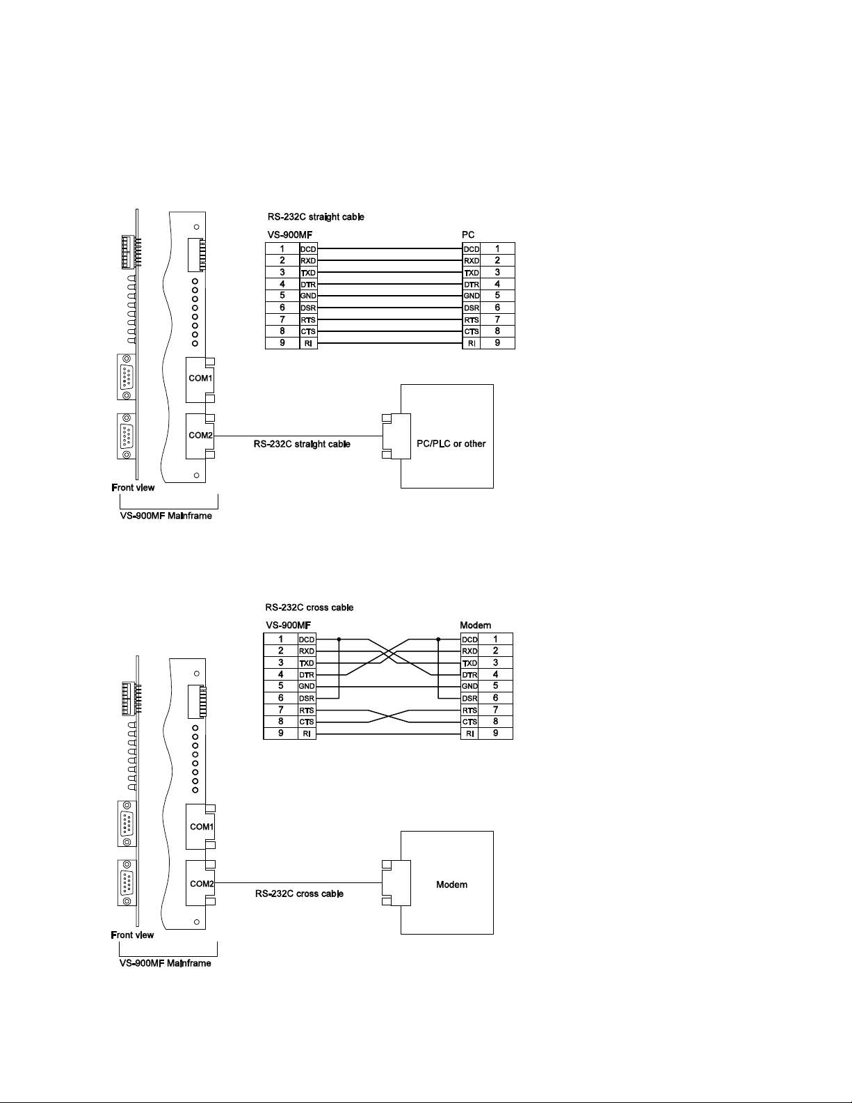
Connecting to the VS-900MF Mainframe
The VS-900MF Mainframe includes two RS-232 serial communication connectors for operation,
monitoring, and programming of the system. Connect to either communication ports with the settings
described on page 5. You can control multiple exchanges from a single serial connection.
Direct Connection
Connection Via Modem
4
Page 5
TOA VS-900 Programmer’s Guide
Communication Specifications
Transmission System: Half-duplex
Baud Rate: 19,200 Bps
Transmission Format: <1 Start Bit> <8 Data bits> <1 Even Parity Bit> <1 Stop Bit>
Message Packaging
Field Name Value Description Direction
DLE
ENQ
DLE
ACK
DLE
STX
Message*
DLE
ETX
BCC**
DLE
ACK
DLE
EOT
10H Delimiter
05H Enquiry
10H Delimiter
06H Acknowledge
10H Delimiter
02H Start of Text
Varies Remote Dial, Data Log
Request or Data Log
10H Delimiter
03H End of Text
Varies Block Check Character
10H Delimiter
06H Acknowledge
10H Delimiter
04H End of Transmission
VS-900 to PC or
PC to VS-900
VS-900 to PC or
PC to VS-900
VS-900 to PC or
PC to VS-900
VS-900 to PC or
PC to VS-900
VS-900 to PC or
PC to VS-900
* See the Remote Dial, Log Data Request or Log Data sections for more information.
** To calculate BCC, take the XOR of the combined Message, DLE, and ETX. (Refer to the shaded area
below). MS Windows Calculator (Scientific mode) is a useful tool for this function.
DLE STX
MESSAGE DLE ETX BCC
5
Page 6

TOA VS-900 Programmer’s Guide
Remote Dial Command
With the protocol below, you can remote dial and perform functions of individual Master Stations in
specific exchanges. To terminate any current functions, precede remote dialing content with “CC” (Clear
function x2).
Field Name Length
(Bytes)
DLE
ENQ
DLE
ACK
DLE
STX
Command
"Remote Dial"
Exchange #
Master Station #
Dialing Contents*
DLE
ETX
BCC
DLE
ACK
DLE
EOT
1 10H Delimiter
1 05H Enquiry
1 10H Delimiter
1 06H Acknowledgement
1 10H Delimiter
1 02H Start Of Text
1 4EH Remote Dialing Command
2 xxH, xxH Add 30H to each digit of the exchange
1 xxH Master Station #2 = (32H)
32 Bytes
Total
1 10H Delimiter
1 03H End Of Text
1 xxH Block Check Character
1 10H Delimiter
1 06H Acknowledge
1 10H Delimiter
1 04H End of Transmission
Value Description Direction
PC to VS-900MF
VS-900MF to PC
number.
Example: Exchange #01 = (30H, 31H)
MS-900 Master Station Dialing
Functions:
30H 0
31H 1
32H 2
33H 3
34H 4
35H 5
36H 6
37H 7
38H 8
39H 9
2AH *
23H #
43H C (Clear)
57H Off-hook
51H On-hook
45H PTT On
52H PTT Off
54H Register Switch On
59H Register Switch Off
58H Transfer
2DH 3 Second dial pause (For C/O lines)
4FH Disable Master Station
50H Enable Master Station
Note: Add "20H" after the designated
dialing contents until the total is 32 bytes
PC to VS-900MF
VS-900MF to PC
PC to VS-900MF
6
Page 7

TOA VS-900 Programmer’s Guide
Log Data Output Request
The VS-900 Log Data Output allows you to monitor most station and system activity. Send the string
below to initiate Log Data flow from individual or multiple exchanges simultaneously. Once the data
stream has been initiated, the VS-900MF will continue to send the log data without re-sending the
request.
Field Name Length
(Bytes)
DLE
ENQ
DLE
ACK
DLE
STX
Log Data
Request
Exchanges
ON/OFF Status
Exchange #01 –
16
DLE
ETX
BCC
DLE
ACK
DLE
EOT
After the initial Log Data Request, the VS-900MF will send an enquiry (DLE & ENQ, 10H & 05H) to the
PC when log data is available in the queue. The PC should then respond with an acknowledgement (DLE
& ACK, 10H & 06H) so the log data will be sent from the VS-900MF. This process will repeat until there is
no information left in log data queue.
1 10H Delimiter
1 05H Enquiry
1 10H Delimiter
1 06H Acknowledgement
1 10H Delimiter
1 02H Start Of Text
1 4FH Log Data Output Request command
2 30H 30H
16 30H or 31H OFF = 30H ON = 31H
1 10H Delimiter
1 03H End Of Text
1 xxH Block Check Character
1 10H Delimiter
1 06H Acknowledge
1 10H Delimiter
1 04H End of Transmission
Value Description Direction
PC to VS-900MF
VS-900MF to PC
PC to VS-900MF
VS-900MF to PC
Field Name Length
(Bytes)
DLE
ENQ
DLE
ACK
DLE
STX
Log Data Sent
Exchange #
Time (HH:MM:SS)
Line #1
Line #2
Line #3
Line #4
*Status #
DLE
ETX
BCC
DLE
ACK
DLE
EOT
1 10H Delimiter
1 05H Enquiry
1 10H Delimiter
1 06H Acknowledge
1 10H Delimiter
1 02H Start Of Text
1 6F Log data
2 xxH xxH Exchange #01 – 16
6 Hours, Minutes, and Seconds
6 Varies, Refer to Appendix A
6 Varies, Refer to Appendix A
6 Varies, Refer to Appendix A
6 Varies, Refer to Appendix A
2 xxH xxH Varies, Refer to Appendix A
1 10H Delimiter
1 03H End Of Text
1 xxH Block Check Character
1 10H Delimiter
1 06H Acknowledge
1 10H Delimiter
1 04H End of Transmission
Value Description Direction
VS-900MF to PC
PC to VS-900MF
VS-90MF to PC
PC to VS-900MF
VS-900MF to PC
7
Page 8

TOA VS-900 Programmer’s Guide
Examples
1. Remote Dialing
The data sequence below will remote dial Master Station #1 in Exchange #1 to dial Sub-Station #105 and
initiate communication. The “CC” (Clear) is included to terminate any current Master Station functions.
Note: The total Dialing Contents must be 32 bytes.
Field Name Length
(Bytes)
DLE
ENQ
DLE
ACK
DLE
STX
Remote Dial
Exchange #
Master Station #
Dialing Contents
DLE
ETX
BCC
DLE
ACK
DLE
EOT
1 10H Delimiter
1 05H Enquiry
1 10H Delimiter
1 06H Acknowledge
1 10H Delimiter
1 02H Start Of Text
1 4EH Remote Dialing
2 30H 31H EXCHANGE # "01"
1 31H MASTER # "1"
32 Bytes 43H 43H 31H 30H 35H
1 10H Delimiter
1 03H End Of Text
1 79H Block Check Character
1 10H Delimiter
1 06H Acknowledge
1 10H Delimiter
1 04H End of Transmission
Value Description Direction
20H 20H 20H 20H 20H 20H
20H 20H 20H 20H 20H 20H
20H 20H 20H 20H 20H 20H
20H 20H 20H 20H 20H 20H
20H 20H 20H
PC to VS-900MF
VS-900MF to PC
Command
"CC105"
PC to VS-900MF
VS-900MF to PC
PC to VS-900MF
8
Page 9

TOA VS-900 Programmer’s Guide
2. Remote Dialing – All Call Paging
The data sequence below will remote dial Master Station #2 in Exchange #3 to initiate All-Call Paging by
dialing *800#. Again, the “CC” (Clear) is included to terminate any current Master Station functions.
Note: The total Dialing Contents must be 32 bytes.
Field Name Length
(Bytes)
DLE
ENQ
DLE
ACK
DLE
STX
Remote Dial
Exchange #
Master Station #
Dialing Contents
DLE
ETX
BCC
DLE
ACK
DLE
EOT
1 10H Delimiter
1 05H Enquiry
1 10H Delimiter
1 06H Acknowledge
1 10H Delimiter
1 02H Start Of Text
1 4EH Remote Dialing Request
2 30H 33H EXCHANGE # "03"
1 32H MASTER # "2"
32 Bytes 43H 43H 2AH 38H 30H 30H
1 10H Delimiter
1 03H End Of Text
1 7DH Block Check Character*
1 10H Delimiter
1 06H Acknowledge
1 10H Delimiter
1 04H End of Transmission
Value Description Direction
23H 20H 20H 20H 20H 20H
20H 20H 20H 20H 20H 20H
20H 20H 20H 20H 20H 20H
20H 20H 20H 20H 20H 20H
20H 20H
PC to VS-900MF
VS-900MF to PC
"CC*800#"
PC to VS-900MF
VS-900MF to PC
PC to VS-900MF
9
Page 10

TOA VS-900 Programmer’s Guide
K
K
3. Log Data Request
The data string below requests Log Data from Exchange #1 (only). After the Log Data Request has been
sent, the Log Data string will be sent to the PC in the format shown on the next page (Example 4. Log
Data Format).
Field Name Length
Value Description Direction
(Bytes)
DLE
ENQ
DLE
ACK
DLE
STX
Log Data
All Exchanges
ON/OFF Status
1 10H Delimiter
1 05H Enquiry
1 10H Delimiter
1 06H Acknowledge
1 10H Delimiter
1 02H Start Of Text
1 4FH Log Data Request
2 30H 30H
16 31H 30H 30H 30H 30H 30H
30H 30H 30H 30H 30H 30H
Exchange #1 Log Data
31H = “On" 30H=”Off”
VS-900MF to PC
PC to VS-900MF
VS-900MF to PC
30H 30H 30H 30H
DLE
ETX
BCC
DLE
ACK
DLE
EOT
1 10H Delimiter
1 03H End Of Text
1 5DH Block Check Character*
1 10H Delimiter
1 06H Acknowledge
1 10H Delimiter
1 04H End of Transmission
PC to VS-900MF
VS-900MF to PC
4. Log Data Format
This example illustrates five data strings that occur when “Normal” priority Sub-station #105 initiates a call
to Master Station #200 at 16:37:23.
Call From Normal Sub-station
Field Name Length
(Bytes)
DLE
ENQ
DLE
AC
DLE
STX
Log Data
Exchange #
Time (HH:MM:SS)
Line #1
Line #2
Line #3
Line #4
Status #
DLE
ETX
BCC
DLE
AC
DLE
EOT
1 10H Delimiter
1 05H Enquiry
1 10H Delimiter
1 06H Acknowledge
1 10H Delimiter
1 02H Start Of Text
1 6FH Log Data
2 30H 31H Exchange # “01”
6 31H 36H 33H 37H 32H 33H Time: “16:37:23"
6 31H 30H 35H 20H 20H 20H Calling Station # “105”
6 32H 30H 30H 20H 20H 20H Called Station # “200”
6 20H 20H 20H 20H 20H 20H Not Used (Blank)
6 20H 20H 20H 20H 20H 20H Not Used (Blank)
2 30H 31H
1 10H Delimiter
1 03H End Of Text
1 78H Block Check Character
1 10H Delimiter
1 06H Acknowledge
1 10H Delimiter
1 04H End of Transmission
Value Description Direction
VS-900 to PC
PC to VS-900
VS-900MF to PC
“01” (Call from Normal
Sub-station)
PC to VS-900
VS-900MF to PC
10
Page 11

Station Call Reception
K
K
K
K
Field Name Length
(Bytes)
DLE
ENQ
DLE
AC
DLE
STX
Log Data
Exchange #
Time (HH:MM:SS)
Line #1
Line #2
Line #3
Line #4
Status #
DLE
ETX
BCC
DLE
AC
DLE
EOT
1 10H Delimiter
1 05H Enquiry
1 10H Delimiter
1 06H Acknowledge
1 10H Delimiter
1 02H Start Of Text
1 6FH Log Data
2 30H 31H Exchange # “01”
6 31H 36H 33H 37H 32H 33H Time: “16:37:23"
6 32H 30H 30H 20H 20H 20H Master Station # “200”
6 20H 20H 20H 20H 20H 20H First Waiting station #
6 20H 20H 20H 20H 20H 20H Not Used (Blank)
6 20H 20H 20H 20H 20H 20H Not Used (Blank)
2 30H 35H
1 10H Delimiter
1 03H End Of Text
1 68H Block Check Character
1 10H Delimiter
1 06H Acknowledge
1 10H Delimiter
1 04H End of Transmission
TOA VS-900 Programmer’s Guide
Value Description Direction
VS-900 to PC
PC to VS-900
(Blank)
“05” (Station call
reception)
VS-900MF to PC
PC to VS-900
VS-900MF to PC
Call Operation Completion
Field Name Length
(Bytes)
DLE
ENQ
DLE
AC
DLE
STX
Log Data
Exchange #
Time (HH:MM:SS)
Line #1
Line #2
Line #3
Line #4
Status #
DLE
ETX
BCC
DLE
AC
DLE
EOT
1 10H Delimiter
1 05H Enquiry
1 10H Delimiter
1 06H Acknowledge
1 10H Delimiter
1 02H Start Of Text
1 6FH Log Data
2 30H 31H Exchange # “01”
6 31H 36H 33H 37H 32H 37H Time: “16:37:27"
6 32H 30H 30H 20H 20H 20H Master Station # “200”
6 31H 30H 35H 20H 20H 20H Called Station # “105”
6 20H 20H 20H 20H 20H 20H Not Used (Blank)
6 20H 20H 20H 20H 20H 20H Not Used (Blank)
2 30H 39H
1 10H Delimiter
1 03H End Of Text
1 74H Block Check Character
1 10H Delimiter
1 06H Acknowledge
1 10H Delimiter
1 04H End of Transmission
Value Description Direction
VS-900 to PC
PC to VS-900
VS-900MF to PC
“09” (Call operation
completion)
PC to VS-900
VS-900MF to PC
11
Page 12

Start of Normal Conversation
K
K
Field Name Length
(Bytes)
DLE
ENQ
DLE
ACK
DLE
STX
Log Data
Exchange #
Time
1 10H Delimiter
1 05H Enquiry
1 10H Delimiter
1 06H Acknowledge
1 10H Delimiter
1 02H Start Of Text
1 6FH Log Data
2 30H 31H Exchange # “01”
6 31H 36H 33H 37H 32H
(HH:MM:SS)
Line #1
Line #2
Line #3
Line #4
Status #
DLE
ETX
BCC
DLE
ACK
DLE
EOT
6 32H 30H 30H 20H 20H
6 31H 30H 35H 20H 20H
6 20H 20H 20H 20H 20H
6 20H 20H 20H 20H 20H
2 31H 30H
1 10H Delimiter
1 03H End Of Text
1 74H Block Check Character
1 10H Delimiter
1 06H Acknowledge
1 10H Delimiter
1 04H End of Transmission
TOA VS-900 Programmer’s Guide
Value Description Direction
VS-900 to PC
PC to VS-900
Time: “16:37:27"
37H
Calling Station # “200”
20H
Called Station # “105”
20H
VS-900MF to PC
Hold Station # (Blank)
20H
Not Used (Blank)
20H
“10” (Start of normal
conversation)
PC to VS-900
VS-900MF to PC
Normal Call Termination
Field Name Length
(Bytes)
DLE
ENQ
DLE
AC
DLE
STX
Log Data
Exchange #
Time (HH:MM:SS)
Line #1
Line #2
Line #3
Line #4
Status #
DLE
ETX
BCC
DLE
AC
DLE
EOT
1 10H Delimiter
1 05H Enquiry
1 10H Delimiter
1 06H Acknowledge
1 10H Delimiter
1 02H Start Of Text
1 6FH Log Data
2 30H 31H Exchange # “01”
6 31H 36H 33H 37H 32H 38H Time: “16:37:28"
6 32H 30H 30H 20H 20H 20H Calling Station # “200”
6 31H 30H 35H 20H 20H 20H Called Station # “105”
6 20H 20H 20H 20H 20H 20H Not Used (Blank)
6 20H 20H 20H 20H 20H 20H Not Used (Blank)
2 33H 32H
1 10H Delimiter
1 03H End Of Text
1 73H Block Check Character
1 10H Delimiter
1 06H Acknowledge
1 10H Delimiter
1 04H End of Transmission
Value Description Direction
VS-900 to PC
PC to VS-900
VS-900MF to PC
“32” (Normal call
termination)
PC to VS-900
VS-900MF to PC
12
Page 13

Summarized version of the above Log Data Format example:
(Shaded areas represent responses required from the PC, all numbers are
in Hex)
Call From Normal Sub-station
10 06 10 02 6F 30 31 31 36 33 37 32 33 31 30 35 20 20 20 32 30 30
10 05
20 20 20 20 20 20 20 20 20 20 20 20 20 20 20 30 31 10 03 78
10 06 10 04
Station Call Reception
10 06 10 02 6F 30 31 31 36 33 37 32 33 32 30 30 20 20 20 20 20 20
10 05
20 20 20 20 20 20 20 20 20 20 20 20 20 20 20 30 35 10 03 68
10 06 10 04
Call Operation Completion
10 06 10 02 6F 30 31 31 36 33 37 32 37 32 30 30 20 20 20 31 30 35
10 05
20 20 20 20 20 20 20 20 20 20 20 20 20 20 20 30 39 10 03 74
10 06 10 04
Start of Normal Conversation
10 06 10 02 6F 30 31 31 36 33 37 32 37 32 30 30 20 20 20 31 30 35
10 05
20 20 20 20 20 20 20 20 20 20 20 20 20 20 20 31 30 10 03 7C
10 06 10 04
Normal Call Termination
10 06 10 02 6F 30 31 31 36 33 37 32 38 32 30 30 20 20 20 31 30 35
10 05
20 20 20 20 20 20 20 20 20 20 20 20 20 20 20 33 32 10 03 73
10 06 10 04
TOA VS-900 Programmer’s Guide
Decimal equivalent of above:
Call From Normal Sub-station
016 005
016 006 016 002 111 048 049 049 054 051 055 050 051 049
048 053 032 032 032 050 048 048 032 032 032 032 032 032 032 032
032 032 032 032 032 032 032 048 049 016 003 120
016 006 016 004
Station Call Reception
016 005
016 006 016 002 111 048 049 049 054 051 055 050 051 050
048 048 032 032 032 032 032 032 032 032 032 032 032 032 032 032
032 032 032 032 032 032 032 048 053 016 003 104
016 006 016 004
Call Operation Completion
016 005
016 006 016 002 111 048 049 049 054 051 055 050 055 050
048 048 032 032 032 049 048 053 032 032 032 032 032 032 032 032
032 032 032 032 032 032 032 048 057 016 003 116
016 006 016 004
Start of Normal Conversation
016 005
016 006 016 002 111 048 049 049 054 051 055 050 055 050
048 048 032 032 032 049 048 053 032 032 032 032 032 032 032 032
032 032 032 032 032 032 032 049 048 016 003 124
016 006 016 004
Normal Call Termination
016 005
016 006 016 002 111 048 049 049 054 051 055 050 056 050
048 048 032 032 032 049 048 053 032 032 032 032 032 032 032 032
032 032 032 032 032 032 032 051 050 016 003 115
016 006 016 004
13
Page 14

Appendix A - Log Status Messages
VS-900 Remote Control and Monitoring Protocol
Status # (2 Bytes)
Dec Hex
01
30H 31H Call from Normal sub-station. Calling station # Called station # - -
02
30H 32H Call from Emergency sub-station. Calling station # Called station # - -
03
30H 33H Call from Master Station (Telephone Master) Calling station # Called station # - -
04
30H 34H Call from C/O line
05
30H 35H Master Station (Telephone Master) reception of a
06
30H 36H Master Station (Telephone Master) reception of a
07
30H 37H Master Station (Telephone Master) reception of a
08
30H 38H Master Station (Telephone Master) reception of a
09
30H 39H Call operation completion at Master Station
10
31H 30H Start of Normal conversation Calling station # Called station # Hold station # -
11
31H 31H Start of Emergency conversation Calling station # Called station # Hold station # -
12
31H 32H Start of C/O line conversation Calling station # Called station # Hold station # -
Description Line 1 Line 2 Line 3 Line 4
C/O line # Called station # - “Axxy " ("xx" is exchange #, and "y" is
C/O line # 1 – 2
Master Station # First waiting station # - -
call from Normal sub-station
Master Station # First waiting station # - -
call from Emergency sub-station
Master Station # First waiting station # - -
call from other Master Station (Telephone Master)
Master Station # First waiting station # - -
C/O line call
Master Station # Called station # - -
(Telephone Master)
13
31H 33H Automatic response to an incoming C/O line call
14
31H 34H Start of Individual-zone or All-zone Paging
15
31H 35H Start of Emergency All-zone Paging
16
31H 36H Start of External Broadcast activation
17
31H 37H Connection of Scan Monitor Operating station # Monitored station # - -
18
19
31H 39H Start of Conference call Call originating station # - - -
20
32H 30H Connection of Conference call Call originating station # Participant station # Participant station # -
21
32H 31H Start of Emergency Conference call Call originating station # - - -
(direct-in dial)
“Axxy " ("xx" is exchange #, and "y" is
C/O line # 1 – 2
"pagxx " ("xx" is paging zone #01 - 19)
"pagxx " ("xx" is paging zone #01 - 19)
"chx " ("x" is the external line # 1 - 4)
Not used
C/O line # - - -
Calling station # Paging # - -
Calling station # Paging # - -
Activated input # Paging # - -
14
Page 15

22
32H 32H Connection of Emergency Conference call Call originating station # Participant station # Participant station # Participant station #
23
32H 33H Automatic Call Forward log Station # to transfer a
24 -
29
30
33H 30H Call termination by disappearance of waiting
31
33H 31H Call termination before dialing completion Operating station # Called station # - -
32
33H 32H Normal call termination Calling station # Called station # Hold station # -
33
33H 33H Receiving C/O line call interruption
34
33H 34H Paging termination Calling station # Paging # - -
35
33H 35H Emergency Paging termination Calling station # Paging # - -
36
33H 36H Termination of external input broadcast.
37
33H 37H Termination of Scan Monitor Operating station # Monitored station # - -
38
33H 38H Termination of Conference Call originating station # Participant station # Participant station # -
39
33H 39H Termination of Emergency Conference Call originating station # Participant station # Participant station # Participant station #
40
34H 30H Line disconnection. Displayed when only a single
41
34H 31H Call termination due to the ringing repetition limit
42
34H 32H Call termination due to the time limit (conversation,
43
34H 33H Call termination (at the called station). Displayed
44
34H 34H Forced call termination (Priority) Calling station # Called party station # Hold station # -
Not Used
stations. Displayed when reception mode is
switched to standby mode.
“Axxy " ("xx" is exchange #, and "y" is
C/O line # 1 - 2
"chx " ("x" is the external line # 1 - 4)
Disconnected station # - - -
line for call transfer or call-back is disconnected.
(No-Answer)
C/O and Paging)
when a received call disappears.
call
Master Station # - - -
C/O line # - - -
Activated input # Paging # - -
Calling station # - - -
Calling station # Called party station # Hold station # -
Calling station # Called party station # - -
Station # a call is
transferred to
--
VS-900 Remote Control and Monitoring Protocol
15
Page 16

Appendix B - ASCII Character Codes
VS-900 Remote Control and Monitoring Protocol
16
 Loading...