

Page 1
Page 2

VIZIO RP56 User Guide
Table of Contents
Chapter Description Page
Introduction 1
1
Features 1
Important Safeguards 2
Package Contents 3
Front Panel Controls 4
Rear Panel Connections 5
Side Connections 6
Universal Remote Control 7
PIP Remote Control 10
2 Connecting Components 12
Power Connection 12
Which Video Connection should I use? 12
Connecting your DVD Player 13
Connecting your HDTV Set-Top Box 17
Connecting your VCR or Video Camera 20
Connecting Coaxial (RF) 22
Connecting External Amplified Speakers 24
Connecting an External Receiver or Amplifier 25
Connecting a Computer 26
3 Getting Started 28
Turning your DLP TV On and Off 28
Adjusting your DLP TV Settings 28
Using the On Screen Display (OSD) 29
Menu Operations 29
OSD Menus and Options 29
Remote Control Operation 33
Using the PIP Remote Control 33
Programming the Universal Remote Control 34
Component Program Codes 34
Searching for Component Codes 34
Checking the Component Codes 35
Reassigning Component Buttons 35
Changing Volume Lock 35
040330 i
Page 3

VIZIO RP56 User Guide
Teaching the Remote Control New Functions 36
Using the Universal Remote Control 36
Using the Picture-In-Picture (PIP) Mode 37
Setting the Sleep Timer 38
Using the Parental Controls 38
Setting a Password 40
To reset your password: 40
4 Maintenance and Troubleshooting 41
Safety Guidelines 41
Compliance 42
Television Antenna Connection Protection 43
Cleaning & Maintenance 44
Cleaning the Screen 44
Cleaning the Exterior 44
Replacing the Filter 45
Replacing the Lamp 46
Status LEDs 48
Normal Operation 48
Error Codes 48
Troubleshooting Guide 49
Telephone & Technical Support 51
Appendix A: Specifications 52
Appendix B: Component Program Codes 53
Appendix C: Overview of V, Inc. Limited Warranty
040330 ii
Page 4

VIZIO RP56 User Guide
1 Introduction
Features
• Huge 56-inch screen.
• HDTV 16:9 Aspect Ratio.
• Only 18.9 inches / 480 mm deep.
• 75.9 lbs/34.5kg light.
• Bright flicker free picture.
• 480P, 720P, 1080I and HDTV signal compatibility.
• 480i support for old NTSC television.
• 640x480 VGA, 800x600 SVGA, 1024x768 XGA computer signal compatibility.
• When displaying film-based media the TV automatically converts the content using 2:3 Pull
Down to minimize motion artifacts to produce a stunning picture.
• Uses DCDi™ Motion Adaptive Deinterlacing for state-of-the-art conversion of interlaced (NTSC
or 1080i HD) to progressive scan.
• DVI input with HDCP for the best display of Digital Video from components such as the VINC
award winning Bravo Multi-Media Player that is recognized as providing the best picture from
DVD and CD.
• High-bandwidth Digital Content Protection (HDCP) will be used for HD Programs and Movies
and the HDTV needs this feature to be able to display the picture.
• Two HD Component Video inputs automatically synchronize to the input.
• Compatible with HDTV from an external HDTV box with DVI, RGB or Component Video
outputs.
• Picture-In-Picture (PIP) modes allow simultaneous display of multiple programs.
• Digital Zoom to make the picture fill the screen. The 16:9 aspect of HDTV translates to a ratio
of 1.77 but widescreen movies are filmed at a ratio of 2.35 and this is the reason there are still
black bars at the top and bottom of the HDTV screen when playing widescreen DVD’s. Using
Digital Zoom can eliminate these black bars although the edges of the picture will be lost.
®
• BBE
• Simulates surround sound with just the two built-in speakers using the SRS
• Selectable fixed Line Out or variable audio output.
• Built-in 15W per channel audio amplifier and speakers.
• OSD menu-driven on screen control system that makes image adjustments a snap.
sound processor to maximize the sound quality.
®
sound processor.
040330 1
Page 5
VIZIO RP56 User Guide
Important Safeguards
• Read all the Safety Instructions and the User Manual before using the DLP TV. Keep these instructions in a safe
place for future reference.
• To avoid the risk of electric shock or component damage, switch off the power before connecting other
components to the DLP TV.
• Unplug the power cord before cleaning the DLP TV. A damp cloth is sufficient for cleaning the DLP TV. Do not
use a liquid or a spray cleaner for cleaning the product. Do not use abrasive cleaners.
• Always use the accessories recommended by the manufacturer to insure compatibility.
• When moving the DLP TV from an area of low temperature to an area of high temperature, condensation may
form on the housing. Do not turn on the DLP TV immediately after this to avoid causing fire, electric shock or
component damage. Do not use the DLP TV near water, e.g. near a bathtub, washbowl, kitchen sink, laundry tub,
swimming pool or in a wet basement.
• Do not place the DLP TV on an unstable cart, stand, or table. If the DLP TV falls, it can injure a person and cause
serious damage to the appliance. Use only a cart or stand recommended by the manufacturer or sold with the
DLP TV.
• A distance of at least 3 feet should be maintained between the DLP TV and any heat source, i.e. radiator, heater,
oven, amplifier etc.
• Slots and openings in the back and bottom of the cabinet are provided for ventilation. To ensure reliable operation
of the DLP TV and to protect it from overheating, be sure these openings are not blocked or covered. Do not place
the DLP TV on a bed, sofa, or similar surface. Do not place the DLP TV near or over a radiator or heat register. Do
not place the DLP TV in a bookcase or cabinet unless proper ventilation is provided.
• Never push any object into the slot on the DLP TV cabinet. It could short circuit parts causing a fire or electric
shock. Never spill liquids on the DLP TV.
• The DLP TV should be operated only from the type of power source indicated on the label. If you are not sure of
the type of power supplied to your home, consult your dealer or local power company.
• The power cable must be replaced when using different voltage from that specified in the User Manual. For more
information, contact your dealer.
• The DLP TV is equipped with a three-pronged grounded plug, a plug with a third (grounding) pin. This plug will fit
only into a grounded power outlet as a safety feature. If your outlet does not accommodate the three-wire plug,
have an electrician install the correct outlet, or use an adapter to ground the appliance safely. Do not defeat the
safety purpose of the grounded plug.
• Unplug the unit during a lightening storm or when it will not be used for long period of time. This will protect the
DLP TV from damage due to power surges.
• Do not overload power strips and extension cords. Overloading can result in fire or electric shock.
• The wall socket shall be installed near the equipment and shall be easily accessible.
• Do not attempt to repair or service the product yourself. Opening or removing the back cover may expose you to
high voltages, the risk of electric shock, and other hazards. If repair is required, please contact your dealer and
refer all servicing to qualified service personnel.
• If any of the following occurs please contact the dealer:
o The power supply or connector fails.
o Liquid sprays or any object drops into the DLP TV.
o The Display is exposed to rain or other moisture.
o The Display is dropped or damaged in any way.
o The performance of the Display changes substantially.
• Operating environment:
Temperature: 32°F~104°F (0°C ~ 40°C)
Humidity: 20% to 85% non-condensing
• Handling the remote control
o Do not drop or mishandle the remote control.
o Do not get the remote control wet. If the remote control gets wet, wipe it dry immediately.
o Avoid heat and humidity.
o When not using the remote control for a long period, remove the batteries.
o Do not take the batteries apart, heat them, or throw them into a fire.
040330 2
Page 6
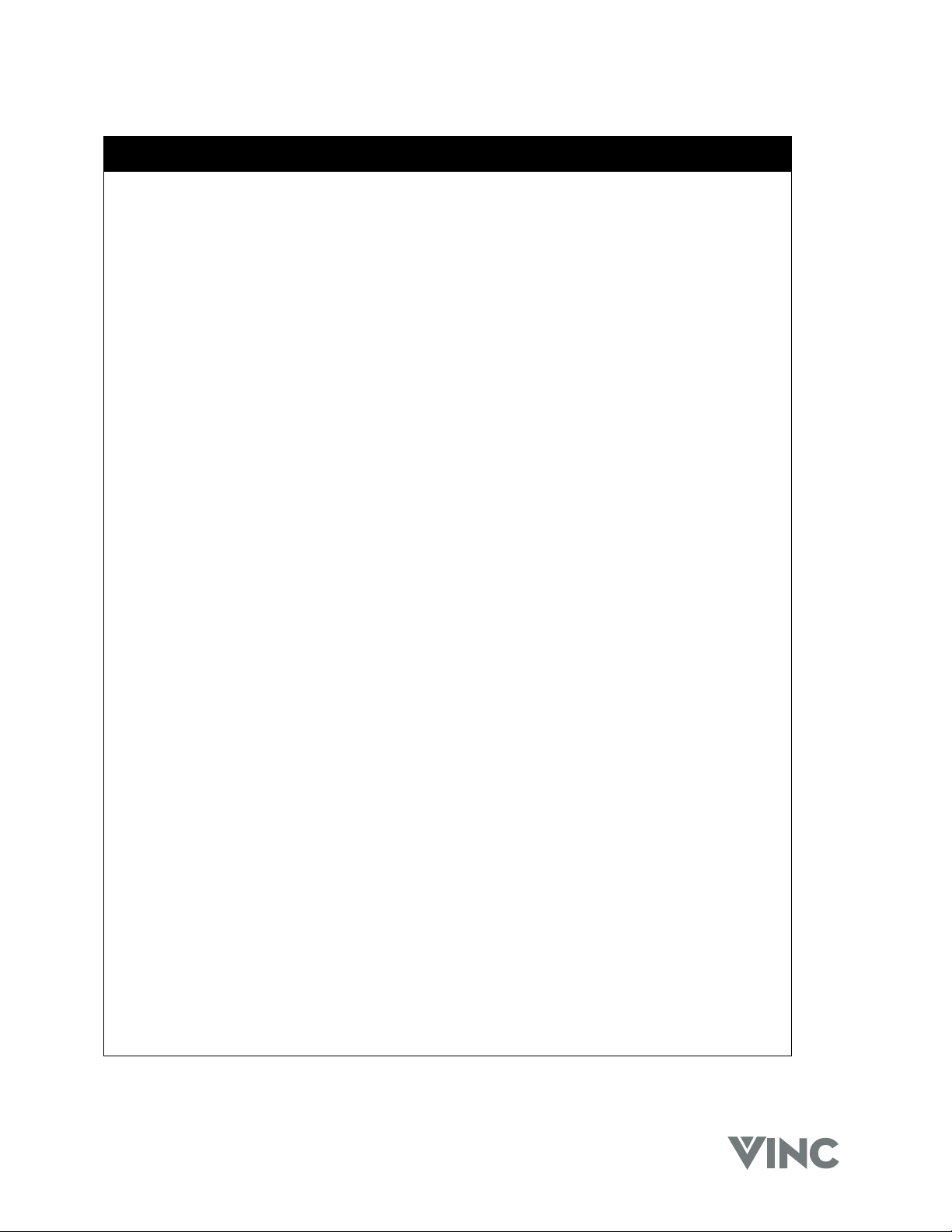
Package Contents
V, Inc Rear Projection DLP TV.
Power cord.
Universal Remote control with two AA batteries.
PIP Remote Control with two AAA batteries.
This User Guide.
VIZIO RP56 User Guide
040330 3
Page 7
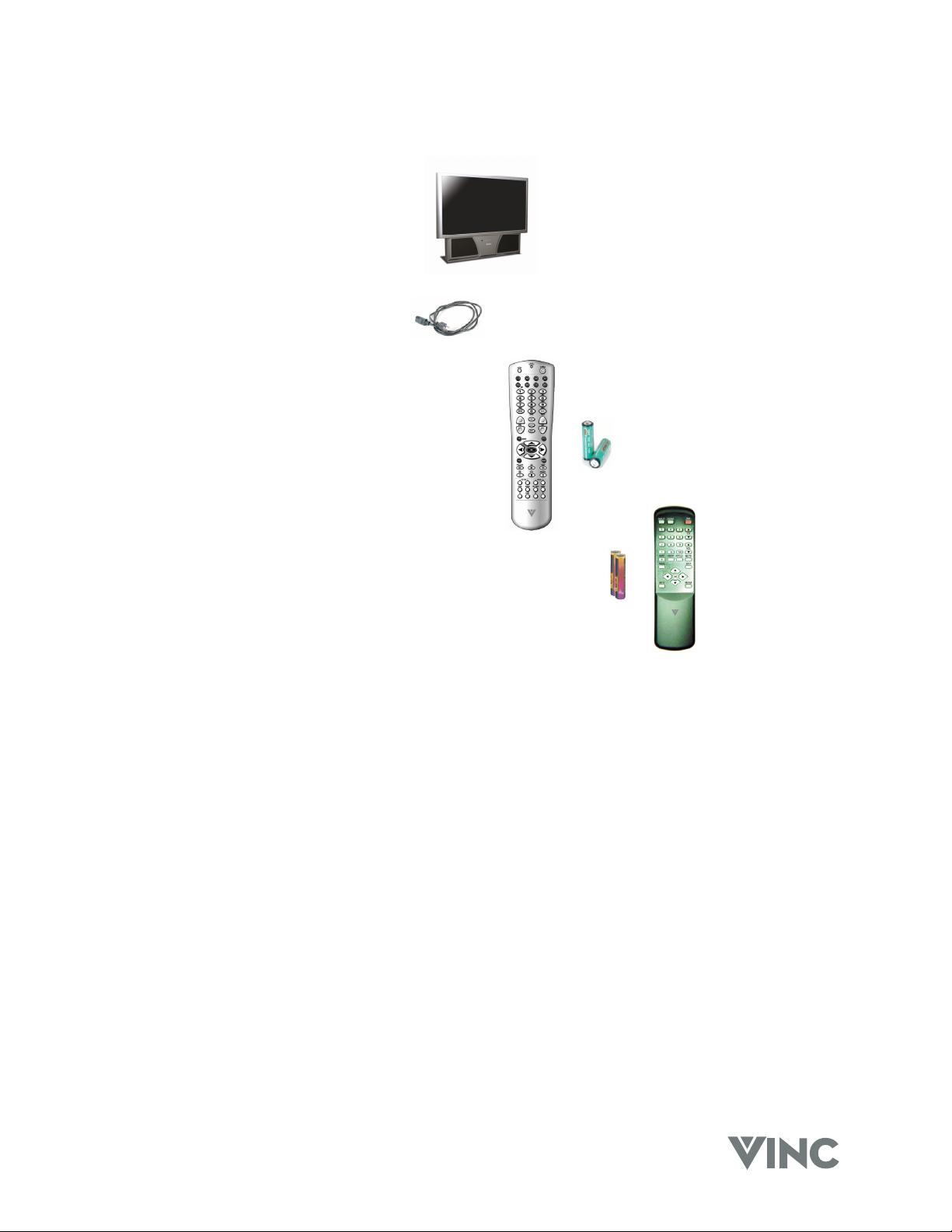
Front Panel Controls
Lamp Status LED
Displays the status of the lamp of
your DLP TV.
Power LED
Lights green when powered on.
Power
Switch the TV on by pressing the
button once. To turn off the TV
press the button twice; the first time
the button is pressed a message will
appear on the screen warning that
the second button press will poweroff the TV.
Input
Repeated pressing of this button
steps through the input sources in a
circulatory sequence. Once you
have selected all of the inputs you
will return to the input you started at.
VIZIO RP56 User Guide
Menu and Exit
Pressing this button activates the
On Screen Display (OSD) and
shows the Main Menu. Pressing
this button again exits (closes) the
OSD.
OK
Pressing this button activates the
OSD and shows the Main Menu.
Channel +/- and Adjustment ▲/▼
Step up (+) or down (-) through TV
channels. While the OSD is active,
these function as adjustment
buttons to select OSD options.
Volume +/- and Adjustment ►/◄
Increase (+) or decrease (-) the speaker volume. While the OSD is active, these function as adjustment
buttons to adjust the OSD options.
Remote Control Sensor
Point the Remote Control here as this is the window through which all of the remote signals pass to
reach the remote sensor.
040330 4
Page 8
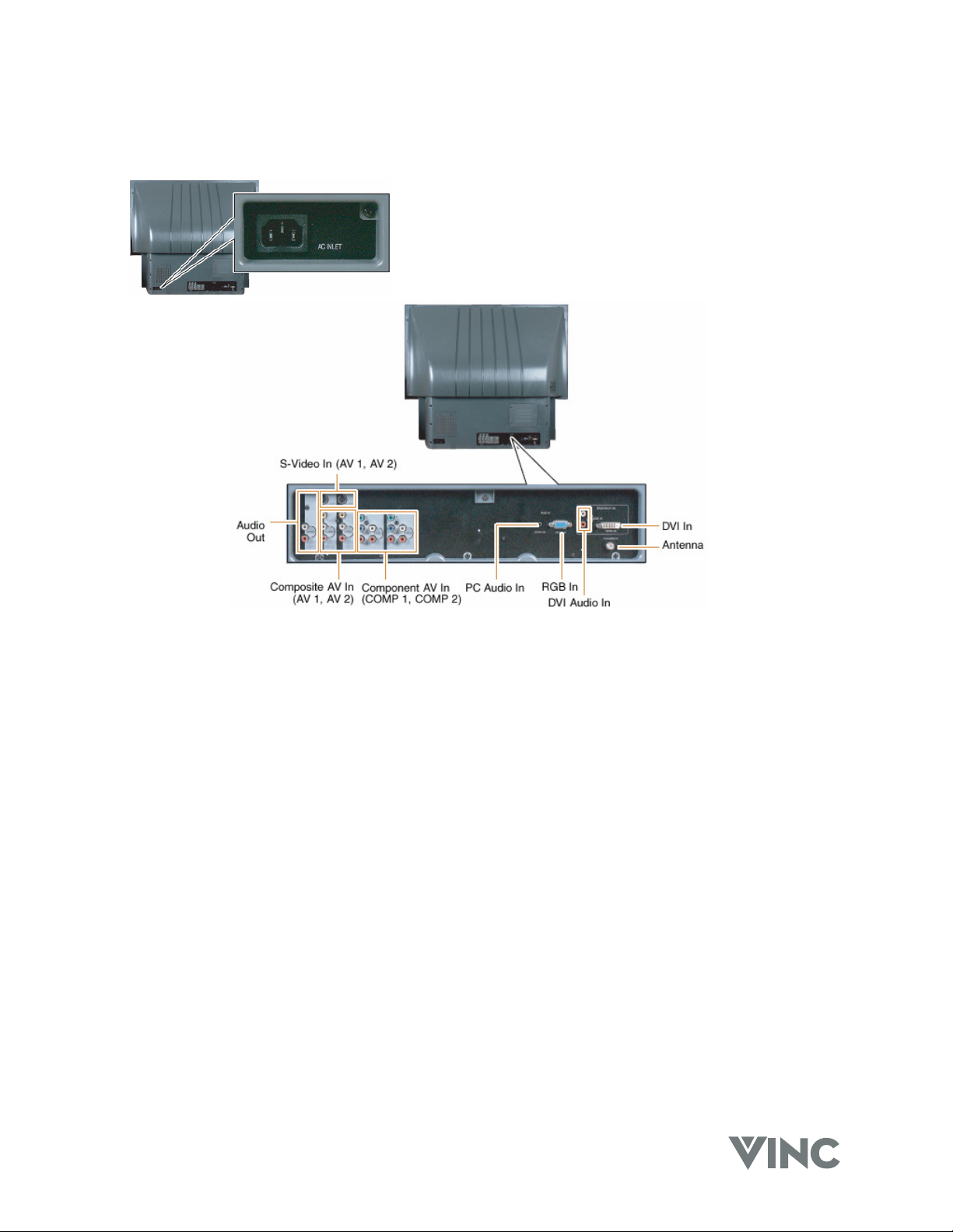
Rear Panel Connections
VIZIO RP56 User Guide
AC Input Socket
Connect one end of the power cord here and connect the other
end of the power cord to a wall socket.
S-Video Connectors
Connect to a VCR, DVD player, satellite or cable box.
Audio Out Connectors
Connect to an AV or Home Theater receiver.
Composite AV Connectors
Connect to a VCR or DVD player.
Component AV Connectors
Connect to a DVD player or set-top box.
PC Audio Connector
Connect the audio from a computer or set-top box.
RGB Connector
Connect the video from a computer or set-top box.
DVI Audio Connectors
Connect the audio from a DVD Multimedia Player, computer or set-top box.
Antenna Connector
Connect a VHF/UHF antenna or cable TV.
DVI Connector
Connect a DVD Multimedia Player, computer or set-top box.
040330 5
Page 9
VIZIO RP56 User Guide
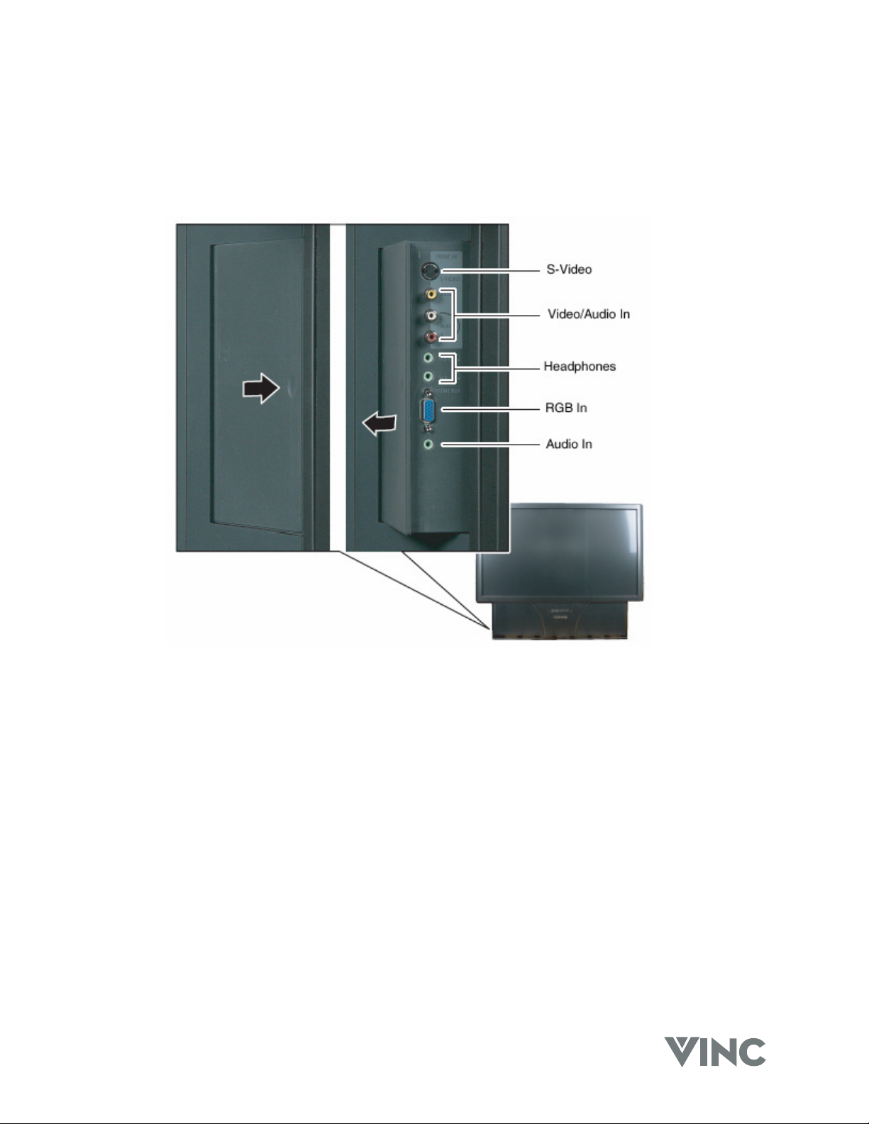
Side Connections
Looking at the front of the DLP, there is a door on the lower left side near the front. Gently press on this
door near the front and it will swing open revealing the input connections that are accessible from the
front. To close again, gently push the door all the way closed until latches (clicks) shut.
S-Video
Connect to a video camcorder.
Video/Audio In
Connect to audio/video equipment such as a video camcorder or digital camera.
Headphones
Connect your headphones to MAIN to listen to the audio for the main picture; the built-in speakers are
turned off when you insert your headphone stereo mini jack plug into here.
Connect your headphones to SUB to listen to the audio for the PIP sub picture.
RGB In
Connect to your laptop computer.
Audio In
Connect to the audio output of your laptop computer.
040330 6
Page 10
VIZIO RP56 User Guide
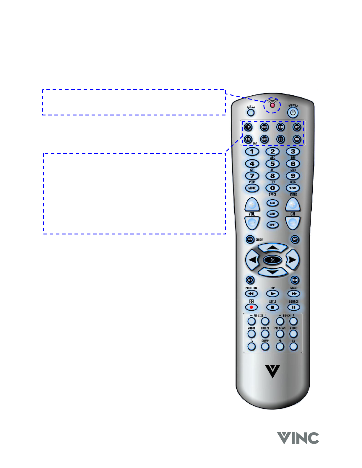
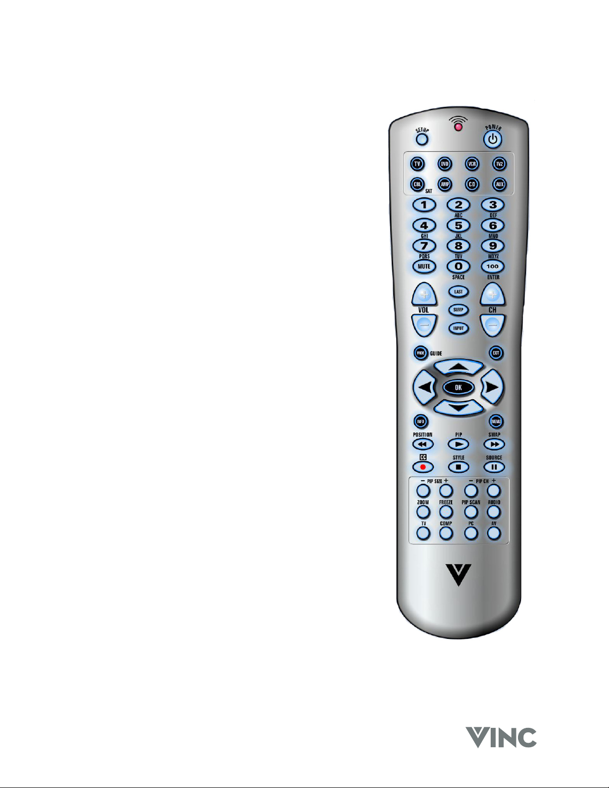
Universal Remote Control
The Universal Remote Control is a comprehensive remote that can be used to control up to eight
different components. For ease of use with minimal room lighting the Remote Control has a back light
that illuminates all of the buttons when any button is pressed. The light will automatically go off a few
seconds after the last button press. The Remote Control button functions are explained below.
Remote LED
Blinks when the Remote Control is being programmed or sending
a command to your DLP TV.
SETUP
Starts all programming sequences.
POWER
Turns on or off your DLP TV or other selected component.
Component buttons
You can program these buttons to select the components you
wish the Remote Control to operate.
TV is pre-programmed to operate your DLP TV.
DVD selects a programmed DVD Player
VCR selects a programmed VCR.
TV2 selects a second programmed TV.
CBL/SAT selects a programmed cable or satellite set-top box.
AMP selects a programmed receiver.
CD selects a programmed CD Player.
AUX selects a programmed component.
Number Pad
Use these buttons to select a TV channel directly by the channel
number or enter the password.
Examples:
For channel 20 press the ‘2’ button and then the ‘0’ button.
For channel 7 press the ‘7’ button and wait about five (5)
seconds; if you do not want the wait five seconds, press the ‘0’
button and then the ‘7’ button.
For channels higher than 99 press the ‘100’ button first.
The Mute button turns the sound off or on.
VOL+ & VOL-
Increase (+) or decrease (-) the sound level from the speakers.
LAST
Switch to the last TV channel viewed.
SLEEP
Activate the Sleep Timer.
INPUT
Change the input source.
CH+ & CH-
Change the TV Channel.
040330 7
Page 11
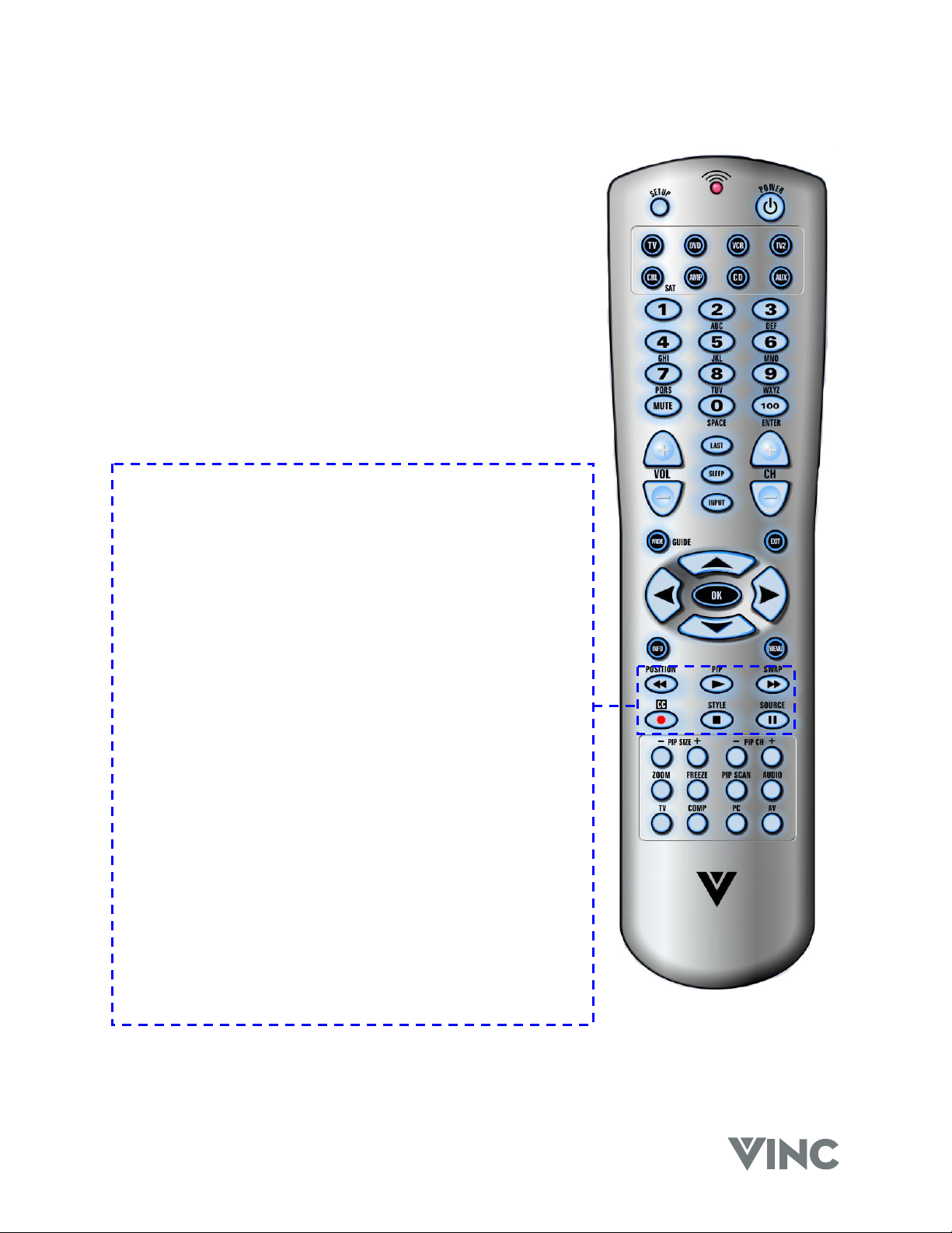
WIDE
Cycle through standard and widescreen viewing modes or access
a programming guide such as the one that comes with a satellite
dish setup. GUIDE does not work in TV mode.
EXIT
Exit the OSD, component or guide menus.
▲, ▼, ◄, ►
Use these buttons to navigate the OSD menus.
OK
Confirm an action, like an Enter button.
INFO
Display the current status of the video source, audio (and channel
number when in TV mode), on the screen of your DLP TV.
MENU
Activates the OSD Menu.
POSITION /
Move the PIP window.
When chosen with one of the Component buttons, tells the VCR,
CD or DVD player to rewind.
VIZIO RP56 User Guide
PIP /
Turn on or off the PIP (Picture In Picture) or POP (Picture On
Picture) mode.
When chosen with one of the Component buttons, tells the VCR,
CD or DVD player to play.
SWAP /
Swap the main picture and sub picture when the PIP or POP
mode is on.
When chosen with one of the Component buttons, tells the VCR,
CD or DVD player to fast forward.
CC /
Turn on or off Closed Caption.
When chosen with the VCR button, tells the VCR to record.
STYLE /
Select the style of the PIP mode.
When chosen with one of the Component buttons, tells the VCR,
CD or DVD player to stop.
SOURCE /
Change the video source for the PIP or POP sub picture.
When chosen with one of the Component buttons, tells the VCR,
CD or DVD player to pause.
040330 8
Page 12
- PIP +
Decrease or increase the size of the PIP window when in the PIP
mode.
- PIP CH +
Changes the TV channel in the PIP window when in the PIP
mode and when TV mode is selected as the PIP video source.
ZOOM
Turn on or off the zoom mode.
FREEZE
Freeze the picture. Note that the video and audio content will
continue to change and when the button is pressed again, turning
off the Freeze mode, the picture will not return to the same point
as when it was frozen.
PIP SCAN
Turn on or off PIP Scan when in the multi-PIP mode. When
turned on, the screen is split into a grid of twelve equal size
pictures the first of which, (top left) is the main picture and the
eleven sub pictures each in turn becomes live for a few seconds
after which it freezes while the other ten take their turn in being
live.
VIZIO RP56 User Guide
Audio
Selects the audio mode.
TV
Selects TV as the video source.
COMP
Alternately selects the component input COMP1 or COMP2.
PC
Alternately selects the rear RGB (VGA), front RGB (VGA) or DVI
input.
AV
Alternately selects the AV1 or AV2 input.
040330 9
Page 13
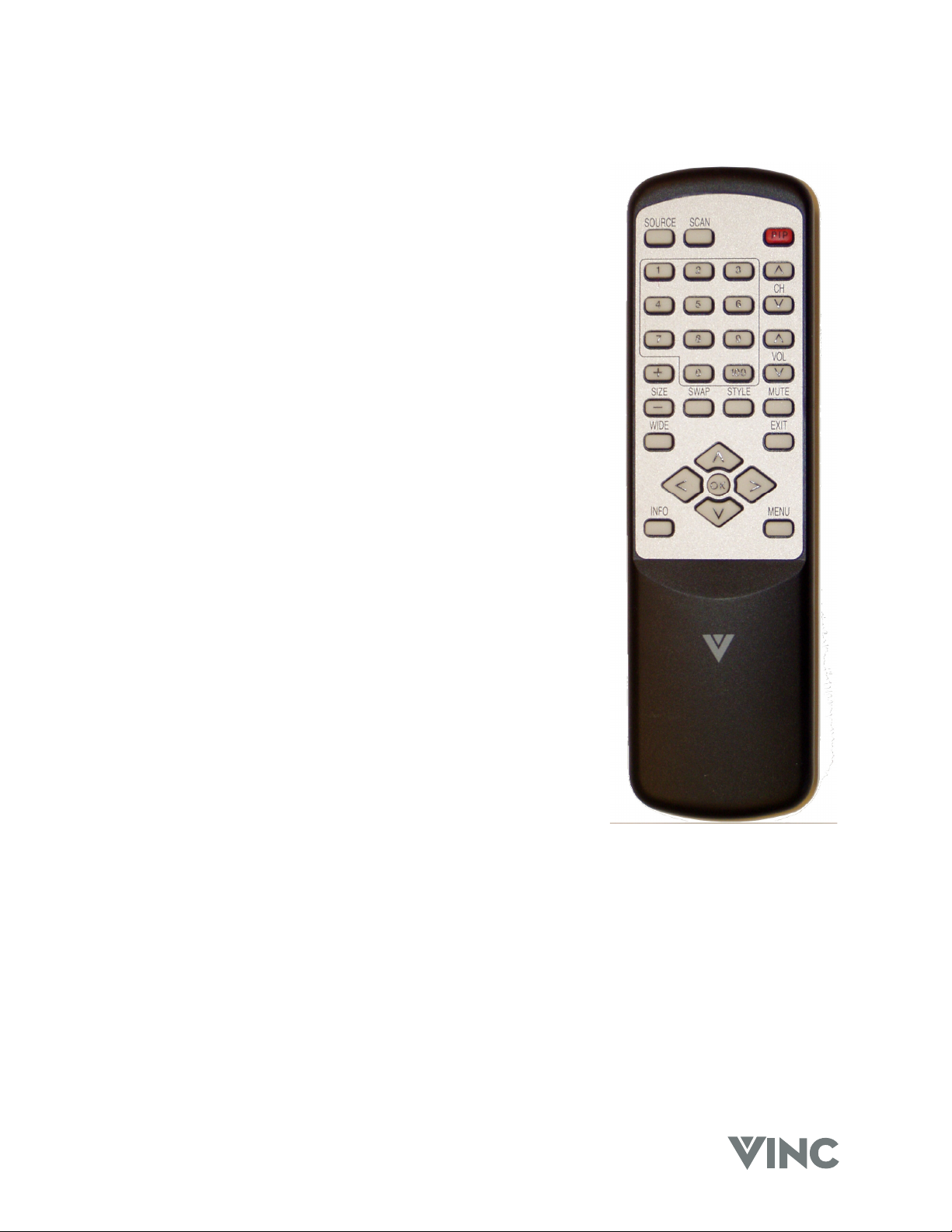
PIP Remote Control
SOURCE
Selects the input source for the PIP window.
SCAN
Turn on or off PIP Scan when in the multi-PIP mode. When turned
on, PIP Scan displays a TV channel for approximately four seconds
and then automatically changes to the next TV channel.
PIP
Turn on or off the PIP mode.
Number Pad
Use these buttons to select a TV channel directly by the channel
number for the active PIP window.
For channels higher than 99 press the ‘100’ button first.
CH U / V
Change the channel in the PIP window.
VOL U / V
Increase or decrease the audio volume for the PIP window.
VIZIO RP56 User Guide
+ SIZE –
Increase or decrease the size of the PIP window.
SWAP
Swap the main picture and sub picture.
STYLE
Select the style of the PIP mode.
MUTE
Turn off or on the sound for the PIP window.
WIDE
Cycle through standard and widescreen viewing modes for the PIP
window
EXIT
Exit the PIP menus.
▲, ▼, ◄, ►
Use these buttons to navigate the On Screen Display (OSD) PIP menus.
OK
Confirm an action, like an Enter button.
INFO
Display the current status of the video source, audio (and channel number if in TV mode) on the screen
of your DLP TV.
MENU
Activates the OSD PIP menu.
040330 10
Page 14
VIZIO RP56 User Guide
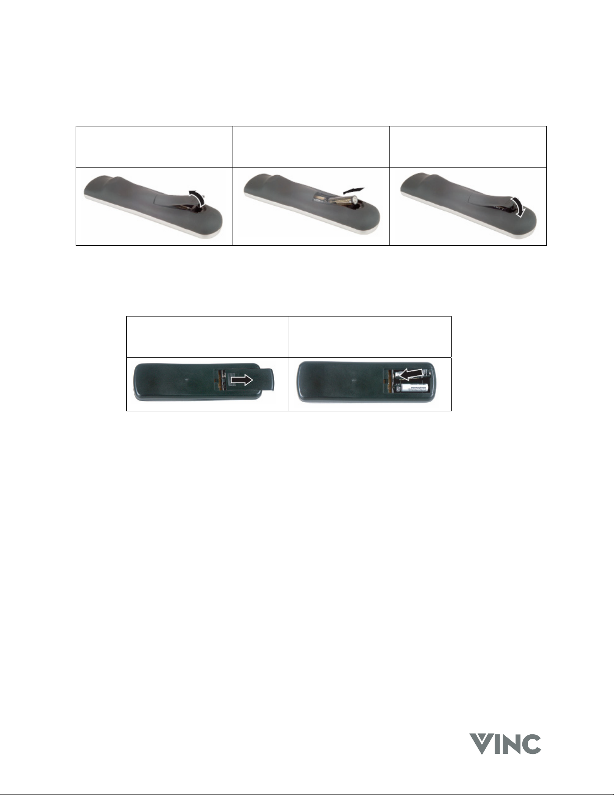
Universal Remote Control Battery Installation and Replacement
When inserting the batteries, make sure they are installed in the correct polarity.
Press latch and lift the cover off. Align the batteries for the correct
polarity (+ / -) shown in the case.
PIP Remote Control Battery Installation and Replacement
When inserting the batteries, make sure they are installed in the correct polarity.
Press and slide the cover off. Align the batteries for the correct
polarity (+ / -) shown in the case.
Replace the cover by sliding it on.
Replace the cover by locating
the tabs and closing it down on
the latch.
040330 11
Page 15

VIZIO RP56 User Guide
2 Connecting Components
Power Connection
Connect the power cord to the AC Input at the rear of the DLP TV and then plug the power cord into an
AC wall socket.
Which Video Connection should I use?
The DLP TV has five different ways to connect your video equipment from a basic one to the most
advanced for digital displays.
Connection
Quality
OK
Basic
Good S-Video. The video signal is separated into two signals, one
Better Component. The video signal is separated into three signals,
Cable and Connector Description
Coaxial RF. This is the only connection that has the audio as
well as the video in this one cable. If you have an antenna, this
is the only way you can connect it to the DLP TV. If you have a
VCR you could connect your antenna/cable to the VCR RF
Input and connect the VCR RF Output to this connector.
Composite. The complete video signal is carried through this
single pin connector. This is the most commonly used video
connector.
containing the black-and-white information and the other
containing the color information. Separating the color in this
way avoids ‘cross color’ effects where closely spaced black
and white lines are erroneously displayed in color and also
enables text to be displayed more sharply.
one containing the black-and-white information and the other
two containing the color information. This enhancement over
S-Video takes advantage of the superior picture provided by
progressive scan DVD players and HDTV formats.
Best Digital Video (DVI). All of the picture information is received
digitally coded and as your DLP TV is a digital display it does
not have to convert the digital to analog. (The other inputs are
converted from analog to digital by the DLP TV.) Movies are
digitally encoded on DVD’s and so using a component such as
the Bravo Multimedia Player from V, Inc. with a DVI output
produces the ultimate picture performance.
040330 12
Page 16
VIZIO RP56 User Guide
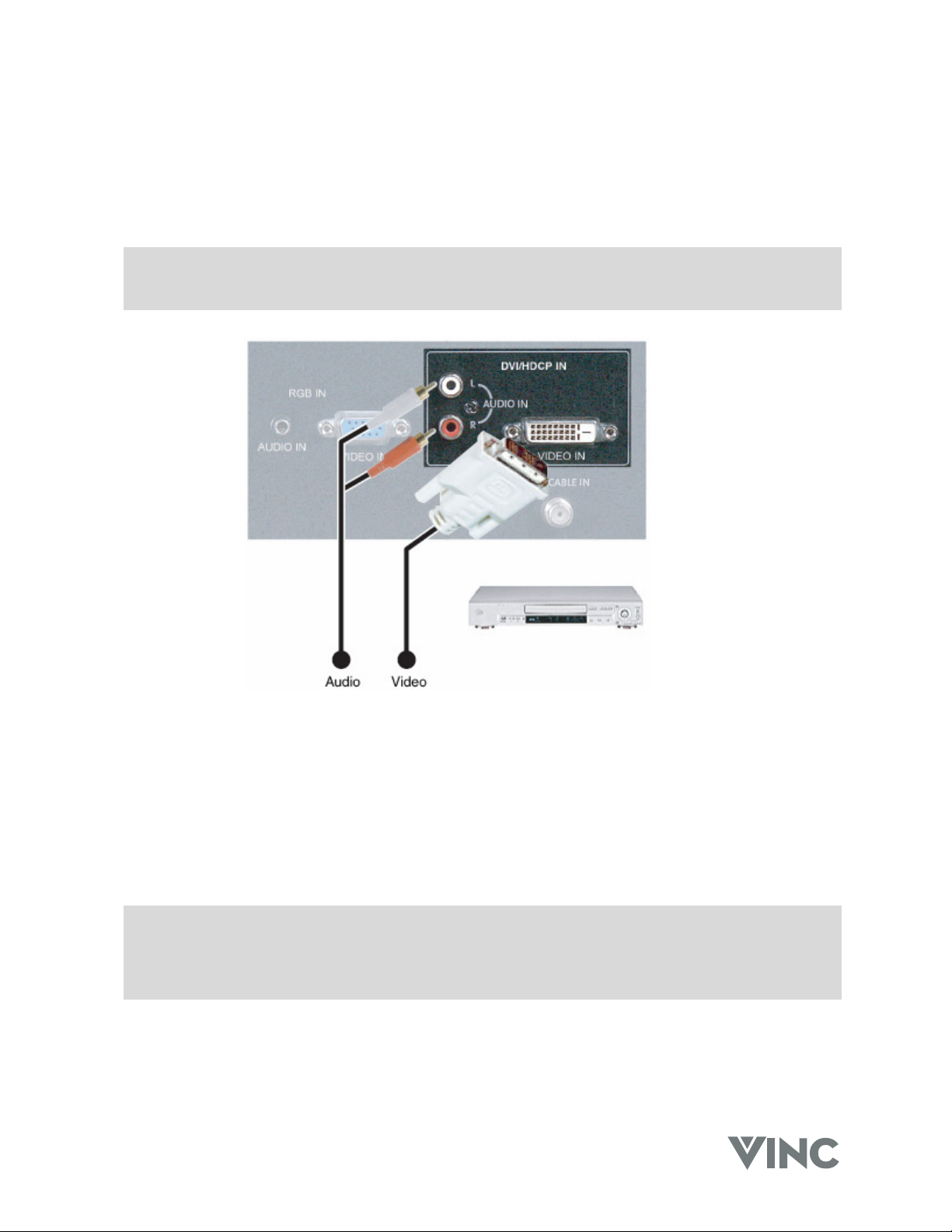
Connecting your DVD Player
Using Digital Video
DVD players that have a digital interface compliant with the DVI (Digital Visual Interface) standard, such
as the Bravo Multimedia Player from V, Inc, should be connected to the DVI input of the DLP TV.
Note:
1. Use TMDS signals conforming to DVI standards. The TMDS input is a single link input.
2. To maintain the display quality use a DVI cable from V, Inc. that is 10 meters or less.
1. Turn off the power to the DLP TV and DVD player.
2. Connect a DVI-D cable to the DVI output of your DVD player and the other end to the DVI input in
the rear of your DLP TV.
3. Connect the Audio Out (Left + Right) on your DVD player to the DVI Audio In L (White) and R
(Red) in the rear of your DLP TV, next to the DVI connector.
4. Turn on the power to the DLP TV and your DVD player.
5. Select DVI using the INPUT button on the front of the DLP TV.
Note: a). The DVI input on your DLP TV supports High-bandwidth Content Protection (HDCP).
HDCP encrypts the transmission between the video source and the digital display for
added security and protection.
b). Refer to your DVD player User Manual for more information about the video output
requirements of the product.
040330 13
Page 17
VIZIO RP56 User Guide
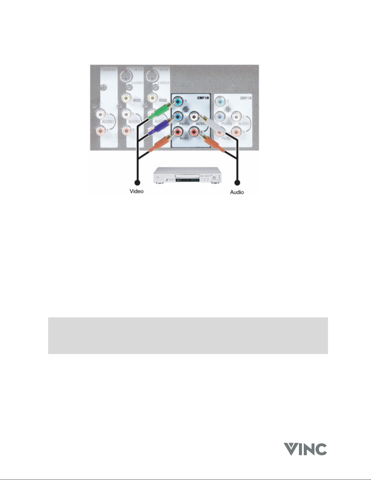
Using Component Video
1. Turn off the power to the DLP TV and DVD player.
2. Connect the Pr or Cr (red color) connector on the rear of your DVD player to the Pr/Cr (red color)
connector in the COMP 1 IN group on the rear of your DLP TV.
3. Connect the Pb or Cb (blue color) connector on the rear of your DVD player to the Pb/Cb (blue
color) connector in the COMP 1 IN group on the rear of your DLP TV.
4. Connect the Y (green color) connector on the rear of your DVD player to the Y (green color)
connector in the COMP 1 IN group on the rear of your DLP TV.
5. Connect the R (red color) and L (white color) audio connectors on the rear of your DVD player to
the R (red color) and L (white color) component audio input connectors in the COMP 1 IN group
on the rear of your DLP TV.
6. Turn on the power to the DLP TV and DVD player.
7. Select COMP 1 using the INPUT button on the front of the DLP TV.
Note: a). If you are already using the COMP 1 IN input for another component, or you do not want to
use the COMP 1 input for the DVD player, you can connect the DVD player to the COMP 2
IN group of connections.
b). Refer to your DVD player User Manual for more information about the video output
requirements of the product.
040330 14
Page 18
VIZIO RP56 User Guide
Using S-Video
1. Turn off the power to the DLP TV and DVD player.
2. Connect the S-Video jack on the rear of your DVD player to the S-Video jack in the AV 2 IN group
on the rear of your DLP TV.
3. Connect the R (red color) and L (white color) audio connectors on the rear of your DVD player to
the R (red color) and L (white color) component audio input connectors in the AV 2 IN group on
the rear of your DLP TV.
4. Turn on the power to the DLP TV and DVD player.
5. Select AV 2 using the INPUT button on the front of the DLP TV.
Note: a). If you are already using the AV 2 IN input for another component, or you do not want to
use the AV 2 input for the DVD player, you can connect the DVD player to the AV 1 IN
group of connections.
b). Refer to your DVD player User Manual for more information about the video output
requirements of the product.
040330 15
Page 19

VIZIO RP56 User Guide
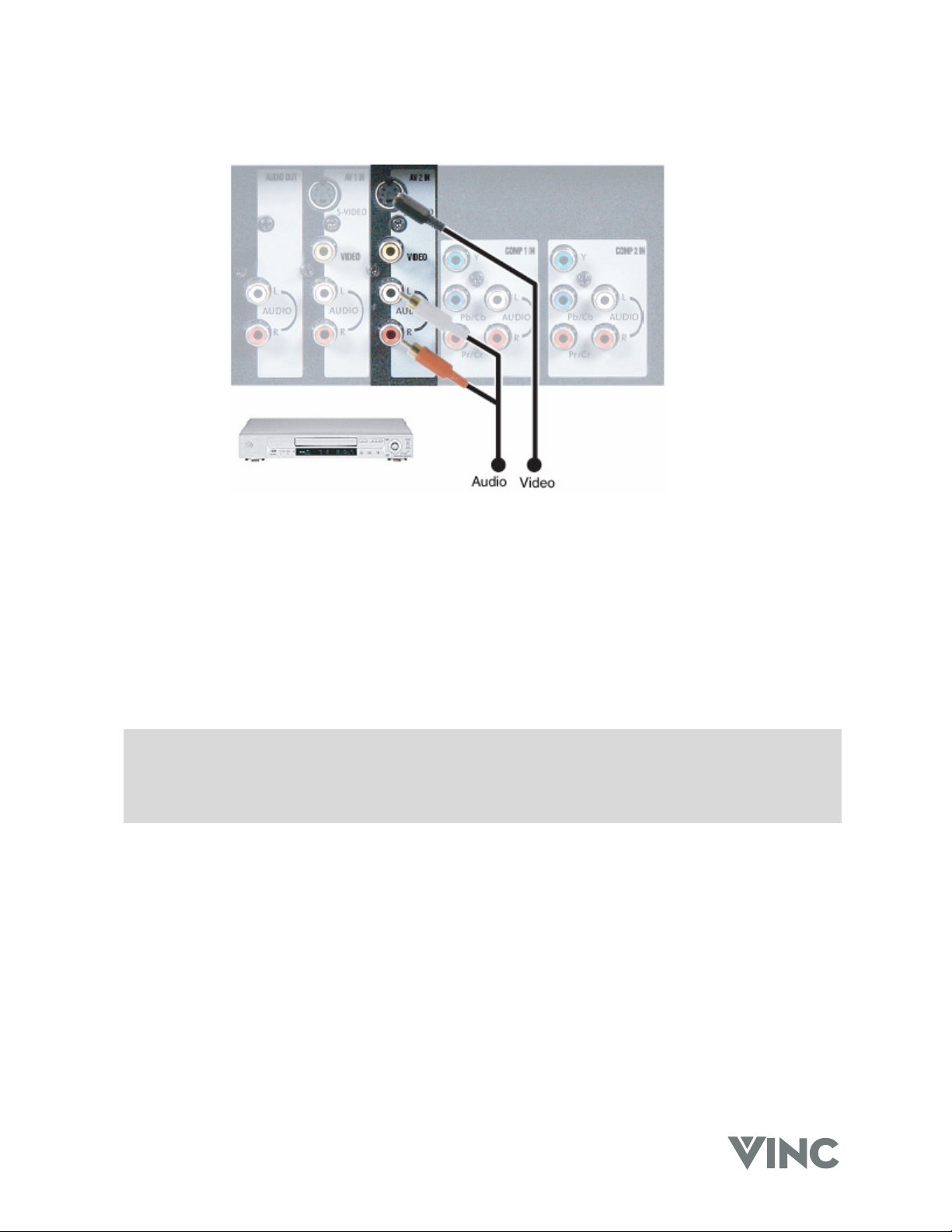
Using Composite Video
1. Turn off the power to the DLP TV and DVD player.
2. Connect the Video (yellow color) connector on the rear of your DVD player to the Video (yellow
color) connector in the AV 2 IN group on the rear of your DLP TV.
3. Connect the R (red color) and L (white color) audio connectors on the rear of your DVD player to
the R (red color) and L (white color) component audio input connectors in the AV 2 IN group on
the rear of your DLP TV.
4. Turn on the power to the DLP TV and DVD player.
5. Select AV 2 using the INPUT button on the front of the DLP TV.
Note: a). If you are already using the AV 2 IN input for another component, or you do not want to
use the AV 2 input for the DVD player, you can connect the DVD player to the AV 1 IN
group of connections.
b). Refer to your DVD player User Manual for more information about the video output
requirements of the product.
040330 16
Page 20

VIZIO RP56 User Guide
Connecting your HDTV Set-Top Box
Using Digital Video
HDTV Set-Top Boxes that have a digital interface compliant with the DVI (Digital Visual Interface)
standard can be connected to the DVI input of the DLP TV.
Note:
3. Use TMDS signals conforming to DVI standards. The TMDS input is a single link input.
4. To maintain the display quality use a DVI cable from V, Inc. that is 10 meters or less.
1. Turn off the power to the DLP TV and HDTV Set-Top Box.
2. Connect a DVI-D cable to the DVI output of your HDTV Set-Top Box and the other end to the DVI
input in the rear of your DLP TV.
3. Connect the Audio Out (Left + Right) on your HDTV Set-Top Box to the DVI Audio In L (White)
and R (Red) in the rear of your DLP TV, next to the DVI connector.
4. Turn on the power to the DLP TV and your HDTV Set-Top Box.
5. Select DVI using the INPUT button on the front of the DLP TV.
Note: a). The DVI input on your DLP TV supports High-bandwidth Content Protection (HDCP).
HDCP encrypts the transmission between the video source and the digital display for
added security and protection.
b). Refer to your HDTV Set-Top Box User Manual for more information about the video output
requirements of the product or consult your Satellite or Cable operator.
040330 17
Page 21

VIZIO RP56 User Guide
Using Component Video
1. Turn off the power to the DLP TV and HDTV Set-Top Box.
2. Connect the Pr or Cr (red color) connector on the rear of your HDTV Set-Top Box to the Pr/Cr
(red color) connector in the COMP 2 IN group on the rear of your DLP TV.
3. Connect the Pb or Cb (blue color) connector on the rear of your HDTV Set-Top Box to the Pb/Cb
(blue color) connector in the COMP 2 IN group on the rear of your DLP TV.
4. Connect the Y (green color) connector on the rear of your HDTV Set-Top Box to the Y (green
color) connector in the COMP 2 IN group on the rear of your DLP TV.
5. Connect the R (red color) and L (white color) audio connectors on the rear of your HDTV Set-Top
Box to the R (red color) and L (white color) component audio input connectors in the COMP 2 IN
group on the rear of your DLP TV.
6. Turn on the power to the DLP TV and HDTV Set-Top Box.
7. Select COMP 2 using the INPUT button on the front of the DLP TV.
Note: a). If you are already using the COMP 2 IN input for another component, or you do not want to
use the COMP 2 input for the HDTV Set-Top Box, you can connect the HDTV Set-Top Box
to the COMP 1 IN group of connections.
b). Refer to your HDTV Set-Top Box User Manual for more information about the video output
requirements of the product or consult your Satellite or Cable operator.
040330 18
Page 22

VIZIO RP56 User Guide
Using RGB Video
1. Turn off the power to the DLP TV and HDTV Set-Top Box.
2. Connect a 15-pin D-Sub RGB cable to the RGB output of your HDTV Set-Top Box and the other
end to the RGB input in the rear of your DLP TV.
3. Connect the Audio Out (Left + Right) on your HDTV Set-Top Box to the RGB Audio In Stereo Mini
Jack in the rear of your DLP TV, next to the RGB connector.
4. Turn on the power to the DLP TV and your HDTV Set-Top Box.
5. Select RGB using the INPUT button on the front of the DLP TV.
Note: Refer to your HDTV Set-Top Box User Manual for more information about the video output
requirements of the product or consult your Satellite or Cable operator.
040330 19
Page 23

Connecting your VCR or Video Camera
Using S-Video
VIZIO RP56 User Guide
1. Turn off the power to the DLP TV and VCR or video camera.
2. Connect the S-Video jack on your VCR or video camera to the S-Video jack in the AV 1 IN group
on the rear of your DLP TV.
3. Connect the R (red color) and L (white color) audio connectors on your VCR or video camera to
the R (red color) and L (white color) component audio input connectors in the AV 1 IN group on
the rear of your DLP TV.
4. Turn on the power to the DLP TV and VCR or video camera.
5. Select AV 1 using the INPUT button on the front of the DLP TV.
Note: a). If you are already using the AV 1 IN input for another component, or you do not want to
use the AV 1 input for the VCR or video camera, you can connect the VCR or video
camera to the AV 2 IN group of connections.
b). Refer to your VCR or video camera User Manual for more information about the video
output requirements of the product.
040330 20
Page 24

VIZIO RP56 User Guide
Using Composite Video
1. Turn off the power to the DLP TV and VCR or video camera.
2. Connect the Video (yellow color) connector on the rear of your VCR or video camera to the Video
(yellow color) connector in the AV 1 IN group on the rear of your DLP TV.
3. Connect the R (red color) and L (white color) audio connectors on the rear of your VCR or video
camera to the R (red color) and L (white color) component audio input connectors in the AV 1 IN
group on the rear of your DLP TV.
4. Turn on the power to the DLP TV and VCR or video camera.
5. Select AV 2 using the INPUT button on the front of the DLP TV.
Note: a). If you are already using the AV 1 IN input for another component, or you do not want to
use the AV 1 input for the VCR or video camera, you can connect the VCR or video
camera to the AV 2 IN group of connections.
b). Refer to your VCR or video camera User Manual for more information about the video
output requirements of the product.
040330 21
Page 25

Connecting Coaxial (RF)
Using your VCR
VIZIO RP56 User Guide
1. Turn off the power to the DLP TV and VCR.
2. Connect the “Output to TV” (RF Out or Antenna Out) connector on the rear of your VCR to the
TV/CABLE IN connector on the rear of your DLP TV.
3. Turn on the power to the DLP TV and VCR.
4. Select TV using the INPUT button on the front of the DLP TV.
5. Select Channel 3 or 4 to match the channel selected on the rear of your VCR.
Note: a). If you have an off-air antenna or cable TV, connect the off-air antenna or TV cable to the
TV/CABLE IN connector on the rear of your VCR.
b). Make sure the antenna or cable TV is correctly grounded.
040330 22
Page 26

VIZIO RP56 User Guide
Using your Antenna or Cable TV
1. Turn off the power to the DLP TV.
2. Connect the coaxial (RF) connector from your antenna or cable box to the TV/CABLE IN connector
on the rear of your DLP TV.
3. Turn on the power to the DLP TV
4. Select TV using the INPUT button on the front of the DLP TV.
Note: Make sure the antenna or cable TV is correctly grounded.
040330 23
Page 27

VIZIO RP56 User Guide
Connecting External Amplified Speakers
If you wish to use external, amplified speakers you may do so by connecting them to the AUDIO OUT
connectors on the rear of your DLP TV.
1. Turn off the power to the DLP TV and external speakers.
2. Connect the R (red color) and L (white color) audio connectors on the rear of your speakers to the
R (red color) and L (white color) audio output connectors in the AUDIO OUT group on the rear of
your DLP TV.
3. Turn on the power to the DLP TV and speakers.
4. Press the MENU button on the front of your DLP TV or on the remote control to activate the On
Screen Display (OSD).
5. Press the TADJUST (- CH) button on the front of your DLP TV four times to highlight AUDIO
ADJUST and press the OK button to select this Sub Menu.
6. Press the TADJUST (- CH) button on the front of your DLP TV five times to highlight REAR
AUDIO OUT and press the ADJUST X (VOL +) to change from FIXED (Line Out) to VARIABLE.
The volume of the audio will still be controlled by the Volume buttons on the front of your DLP TV
or on the remote control.
040330 24
Page 28

VIZIO RP56 User Guide
Connecting an External Receiver or Amplifier
You can connect an external receiver or amplifier to your DLP TV. Your DLP TV is equipped with an
external speaker switch that can automatically send a remote turn-on/off signal to the connected
external receiver or amplifier.
1. Turn off the power to the DLP TV and receiver or amplifier.
2. Connect the R (red color) and L (white color) audio connectors on the rear of your receiver or
amplifier to the R (red color) and L (white color) audio output connectors in the AUDIO OUT
group on the rear of your DLP TV.
3. Turn on the power to the DLP TV and receiver or amplifier.
4. Press the MENU button on the front of your DLP TV or on the remote control to activate the On
Screen Display (OSD).
5. Press the TADJUST (- CH) button on the front of your DLP TV four times to highlight AUDIO
ADJUST and press the OK button to select this Sub Menu.
6. Press the TADJUST (- CH) button on the front of your DLP TV five times to highlight REAR
AUDIO OUT and press the ADJUST X (VOL +) to change from FIXED (Line Out) to VARIABLE
so that you can use the Volume buttons on the front of your DLP TV or on the remote control or
change from VARIABLE to FIXED to use the Volume buttons on the receiver or amplifier.
040330 25
Page 29

Connecting a Computer
Using DVI Video
VIZIO RP56 User Guide
1. Turn off the power to the DLP TV and Computer.
2. Connect a DVI-D cable to the DVI output of your computer and the other end to the DVI input in
the rear of your DLP TV.
3. Connect the Audio Out mini-jack on your computer to the DVI Audio In L (White) and R (Red) in
the rear of your DLP TV, next to the DVI connector.
4. Turn on the power to the DLP TV and your computer.
5. Select DVI using the INPUT button on the front of the DLP TV.
Note: a). The DVI input on your DLP TV supports High-bandwidth Content Protection (HDCP).
HDCP encrypts the transmission between the video source and the digital display for
added security and protection.
b). Refer to your computer User Manual for more information about the video output
requirements of the product.
040330 26
Page 30

VIZIO RP56 User Guide
Using RGB Video
1. Turn off the power to the DLP TV and Computer.
2. Connect a 15-pin D-Sub RGB cable to the RGB output of your computer and the other end to the
RGB input in the rear of your DLP TV.
3. Connect the Audio Out mini jack on your computer to the RGB Audio In L (White) and R (Red) in
the rear of your DLP TV, next to the RGB connector.
4. Turn on the power to the DLP TV and your computer.
5. Select RGB using the INPUT button on the front of the DLP TV.
Note: Refer to your computer User Manual for more information about the video output
requirements of the product.
040330 27
Page 31

VIZIO RP56 User Guide
3 Getting Started
Turning your DLP TV On and Off
1. Plug the power cord into an AC wall socket. The POWER indicator on the front panel will light
green.
2. Press the POWER button on the front panel or the POWER button on the Remote Control to
power on the DLP TV. The LAMP STATUS indicator will start flashing while the lamp heats and
once the lamp is warm enough the indicator will stay lit green and the picture will begin to appear
on the screen.
3. When the DVP TV is on, press the POWER button on the front panel or the POWER button on
the Remote Control and a message will appear on the screen warning you that you are about to
power off the DLP TV. This is because once the DVP TV has been turned off you cannot turn it
on again until at least 45 seconds later as a protection feature for the lamp which will be damaged
if it is turned on too soon after being on. The LAMP STATUS indicator will start flashing until the
protection time has passed and then the indicator go off and the DLP TV will be in the standby
mode.
Adjusting your DLP TV Settings
Volume
To increase the volume, press and hold the VOL + button on the front panel or Remote Control until the
desired level is reached.
To decrease the volume, press and hold the - VOL button on the front panel or Remote Control until the
desired level is reached.
TV Channels
To step up through the available TV channels press the CH + button on the front panel or Remote
Control once for the next channel or hold it depressed until the desired channel is reached.
To step down through the available TV channels press the - CH button on the front panel or Remote
Control once for the previous channel or hold it depressed until the desired channel is reached.
Mute
Press the MUTE button on the Remote Control to turn off the sound; press the button again to cancel
the MUTE feature and turn the sound on.
Sleep
The Sleep Timer can be set to turn the DLP TV off in 30, 60, 90 or 120 minutes.
Press the SLEEP button on the Remote Control once and the display on the screen will show the timer
is off. Press it again and the display will change to 30 minutes, press it again and the display will
change to 60 minutes, again for the display to show 90 minutes and again for 120 minutes. The timer
will start once the display disappears. If you want to cancel the Sleep Timer, keep press the SLEEP
button to get to 120 minutes and then press it once more so the display shows off.
Wide
Using this feature you can watch video content in Stretch, Center, Panoramic or Zoom mode.
Press the WIDE button on the Remote Control and switch between the modes.
040330 28
Page 32

VIZIO RP56 User Guide
Using the On Screen Display (OSD)
The DLP TV features an on-screen display (OSD) that lets the user adjust and save contrast,
brightness and other settings. The DLP TV saves changes made to the settings even if the DLP TV is
turned off.
Menu Operations
The OSD consists of a Main Menu of items and each of these items has a Sub Menu associated with it
that the OSD will switch to when the item is selected.
1. Press the MENU button on the front of the DLP
TV or the Remote Control and the Main Menu
will be displayed on the screen, as shown
opposite.
2. Press the TADJUST (- CH) or ADJUST S (CH
+) button on the front panel to highlight the
feature you wish to select.
3. Press the OK button on the front panel to select
the feature. The Main Menu will now change to the Sub Menu of the feature selected.
4. Press the TADJUST (- CH) or ADJUST S (CH +) button on the front panel to highlight the
option you wish to adjust and press the OK button on the front panel.
5. Adjust the level or change the setting of the selected option by pressing ◄ ADJUST (- VOL) or
ADJUST X (VOL +) on the front panel.
6. Repeat steps 4 and 5 to adjust additional options.
7. Once the adjustment is completed press the MENU on the front panel repeatedly to return to
the Main Menu or exit the OSD.
OSD Menus and Options
The OSD menus and options are used to adjust various settings on your DLP TV.
PICTURE ADJUST – TV Modes
CONTRAST – Adjusts the contrast of the picture.
BRIGHTNESS – Adjusts the brightness of the picture.
Users may need to readjust the brightness after the DLP
TV warms up.
COLOR – Adjusts the color saturation making colors
more intense.
TINT – Adjusts the color of flesh tones.
SHARPNESS – Adjust the amount of detail
enhancement.
WIDE FORMAT – Adjusts the screen width to
STRETCH, CENTER, PANORAMIC, or ZOOM viewing
mode.
040330 29
Page 33

VIZIO RP56 User Guide
PICTURE ADJUST – PC Modes
CONTRAST – Adjusts the contrast of the picture.
BRIGHTNESS – Adjusts the brightness of the picture.
Users may need to readjust the brightness after the DLP
TV warms up.
H POSITION – Adjusts the horizontal screen position.
V POSITION – Adjusts the vertical screen position.
AUTO CONFIG – Automatically adjusts to the best
settings.
ADC CLOCK – Removes any vertical distortion and
clears or sharpens the displayed characters.
ADC PHASE – Removes any horizontal distortion and
clears or sharpens the displayed characters.
WIDE FORMAT - Adjusts the screen width to
STRETCH, CENTER, PANORAMIC, or ZOOM viewing
mode.
PIP SETUP
PIP STYLE – Turns PIP mode on or off, or chooses one
of the following pre-set modes:
SPLIT – The screen is divided in half. The left
side is the main picture and the right side is the
sub-picture.
POP – The screen is in the 16:9 mode and
divided in half. The left side is the main picture
and the right side is the sub-picture.
MAIN + 3 – The main picture is on the left and
there are three small sub-picture windows on the
right.
MAIN + 7 – The main picture is on the bottom
left and there are four small sub-picture windows
across the top and three small sub-pictures on
the right.
SCAN – The screen is divided into 12 small sub-
pictures.
WIDE – Changes the sub-picture size. Choose between
4:3 and 16:9.
SIZE – Changes the size of the sub-picture.
H POSITION – Moves the sub-picture left or right.
V POSITION – Moves the sub-picture up or down.
TRANSPARENCY – Adjusts the sub-picture
transparency.
040330 30
Page 34

VIZIO RP56 User Guide
INPUT SETUP
MAIN INPUT – Selects the video input source for the
main picture.
DVI TYPE – Selects between VIDEO and COMPUTER
components if the DVI connection is being used.
PIP INPUT – Selects the video input source for the sub-
picture when PIP is turned on.
TV TUNER SETUP
ANTENNA/CABLE – Sets the source for the tuner.
Select CABLE (for cable or a satellite dish) or
ANTENNA.
AUTOPROGRAM CHANNELS – When TV is the
selected video input source, the DLP TV adds all
channels that have a signal to the channel list.
CHANNEL – Displays the current TV channel and lets
users skip or add the current channel to the channel list.
CLOSED CAPTION – Turns closed captioning on and
off. AUTO automatically turns captioning on when the
DLP TV is muted.
CAPTION STYLE – Sets the display style for closed
captioning.
AUDIO ADJUST
BASS – Adjusts the bass.
TREBLE – Adjust the treble.
BALANCE – Adjusts the balance level between the
channels.
TV SOUND – Changes the sound output for TV
programs. Switch between STEREO, SAP (Second
Audio Program) or MONO for audio simulcasts. The TV
program must support the output option.
INTERNAL SPEAKERS – Turns the built-in speakers on
or off.
REAR AUDIO OUT – Changes the audio output options
on the DLP TV.
FIXED – Bypasses the DLP TVs internal sound
controls.
VARIABLE – Adjusts the type of output the DLP TV
sends to the internal speakers or the audio output
jack.
SUB HEADPHONE VOL – Adjusts the volume to the
sub-picture headphone jack.
EFFECT – Adds simulated audio effects. Switch
between BBE, SRS, VIVAHD3D, EALA and STEREO.
040330 31
Page 35

VIZIO RP56 User Guide
PARENTAL CONTROLS
ACCESS CODE – A password is required to open the
PARENTAL CONTROLS menu. Users need the remote
control to use this option.
SPECIAL FEATURES
OSD H POSITION – Adjusts the horizontal position of
the OSD within the display image.
OSD V POSITION – Adjusts the vertical position of the
OSD within the display image.
OSD TIMEOUT – Specifies the number of seconds the
OSD menu is displayed before it automatically turns off.
COLOR TEMPERATURE – Adjusts the color
temperature to three preset modes. Select COOL,
NEUTRAL or WARM.
LANGUAGE – Chances the language of the OSD menu.
Select ENGLISH, FRENCH or SPANISH.
SYSTEM INFO – Displays current system information.
RESET ALL SETTINGS – Resets all settings, except
the parental controls and lamp timer, to the factory
defaults.
RESET LAMP TIMER – Resets the lamp timer after
replacing the projection lamp.
SLEEP TIMER – Turns sleep timer on and off and
selects the number of minutes the DLP TV waits before
it automatically turns off. User can specify 30, 60, 90 or
120 minutes.
040330 32
Page 36

VIZIO RP56 User Guide
Remote Control Operation
Common Sense Cautions
Do not drop or mishandle the remote control.
Do not get the remote control wet. If the remote control gets wet,
wipe it dry immediately.
Avoid heat and humidity.
When not using the remote control for a long period, remove the
batteries.
Do not take apart the batteries, heat them, or throw them into a
fire.
Using the PIP Remote Control
The PIP Remote Control is exclusively for control of all PIP mode options. In addition, the Universal
Remote Control can also be used to control the PIP mode options.
o Press the red PIP button on the PIP Remote Control to activate the PIP (Picture-In-Picture)
mode. The PIP (sub screen) window will appear on the screen superimposed on the main
screen. When you press this button again it will deactivate the PIP mode and the window will
disappear.
o Press the SIZE + button to increase the size of the PIP window. Each press of the button will
increase the window size one step; holding the button depressed will cause size of the window
to be increased step-by-step automatically.
o Press the SIZE - button to decrease the size of the PIP window. Each press of the button will
decrease the window size one step; holding the button depressed will cause size of the window
to be decreased step-by-step automatically.
o When the PIP window is visible, press the SWAP button and the main picture will switch to PIP
window and the PIP picture will replace it on the main screen. Press the SWAP button again
and the pictures will switch back again.
o When the PIP window is visible, press the STYLE button and the DLP TV will show the main
and sub pictures as a split screen with the screen being divided equally between the two
pictures but the content will be squeezed into the half width so that people will appear long and
thin. Press the STYLE button again and will change to POP (Picture-On-Picture) mode in
which both pictures are equal again but this time the height is adjusted to match the width of
each picture so that people are in the correct proportions. Press the STYLE button again and
the format will change to Main+3 mode which means there is a large main picture and three
smaller sub pictures stacked on the right side of the screen; each one of the sub pictures in turn
becomes live for a few seconds after which it freezes while the other two take their turn in being
live. Press the STYLE button again and the format will change to Main+7 mode which means
there is one larger main picture and seven smaller sub pictures arranged along the top and
right edge of the screen and they alternate between live and freeze as for the previous mode.
Press the STYLE button again and the format will change to Scan mode in which the screen is
split into a grid of twelve equal size pictures the first of which, (top left) is the main picture and
the eleven sub pictures are refreshed as in the previous two modes. Press the STYLE button
again and the format will change to PIP mode, which is where cycle of choices began.
o Press the SOURCE button one or more times to select the video input desired.
Note: The DVI or RGB input cannot be used as a sub picture source.
040330 33
Page 37

VIZIO RP56 User Guide
Programming the Universal Remote Control
The TV Selection button has already been programmed to work with your Vizio RP56 DLP TV (program
code 0080). You can program the other seven Component buttons on the Universal Remote Control to
operate other components you have.
1. Turn on the component.
2. Choose a Component button you want to program, (for example CBL for a cable box or
DVD for a DVD Player), on the Universal Remote Control and press this button.
3. Press and hold the SETUP button until the LED on the Remote Control flashes twice.
4. Refer to the table below that lists components and manufacturers and their relevant
program codes to find the programming code for the component and, using the number
buttons, enter the programming code. If the code is accepted the LED will flash twice
after the last digit of the programming code is entered.
5. Point the Universal Remote Control at the component and press the POWER button; the
component should power off. If the component does not turn off and there is more than
one programming code listed for the manufacturer and component, try the next code in
the list for that manufacturer until you find the correct one for your component.
Note: If you cannot find your manufacturer in the component list or if none of the programming
codes work, you can use the Remote Control to search for the correct component code.
See “Searching for Component Codes” below.
Component Program Codes
Use the codes in Appendix B to program the Universal Remote Control to work with your existing audio
and video components.
Searching for Component Codes
If you cannot find the manufacturer in the component list or the program code does not work, you can
use the remote control to search for the correct component code.
1. Turn on the component.
2. Press the matching component button on the Universal Remote Control
3. Press and hold the SETUP button until the LED flashes twice.
4. Press 9 9 1. After this number sequence has been entered the LED will flash twice.
5. Point the Universal Remote Control at the component and alternate between pressing the
POWER button and the component button on the remote control until the component turns off.
If the component still does not respond, clear the component button as described in the next three-step
process, then repeat the search procedure.
1. Make sure that the component is turned on.
2. Press and hold the SETUP button on the Universal Remote Control until the LED flashes twice.
3. Press 9 9 2, then press the component button on the Universal Remote Control twice.
040330 34
Page 38

VIZIO RP56 User Guide
Checking the Component Codes
If you have set up the Universal Remote Control using the “Searching for Component Code” procedure,
you may need to find out which four-digit code is operating your equipment.
To find out which code is operating your TV:
1. Press the TV button once.
2. Press the hold the SETUP button until the LED blinks twice, then release the SETUP button.
3. Enter 9 9 0. After this number sequence has been entered the LED will flash twice.
4. To view the code for the first digit, press 1 once. Wait 3 seconds, count the LED blinks (i.e., 3
blinks = 3) and write down the number.
Note: If a code digit is “0”, the LED will not blink.
5. Repeat step # 4 three more times for the remaining digits. Use 2 for the second digit. Use 3 for
the third digit, and 4 for the fourth digit.
6. To check the codes for your other components, repeat steps 1 through 5, but substitute the
appropriate key (i.e., AUX, CBL, VCR, SAT, CD, AMP, or DVD) for the component you are
checking. As before, write down each four-digit code.
Reassigning Component Buttons
You can reassign the component buttons on the remote control if you have more than one of the same
type of component.
Example:
If you are using the Universal Remote to control your cable (CBL), CD, DVD, TV and two VCRs, you
can reassign the satellite (SAT) button as a second VCR button.
1. Press and hold the SETUP button until the LED flashes twice.
2. Press 9 9 2. After this number sequence has been entered the LED will flash twice.
3. Press the component button that you want (VCR) once, and then press the component button
that you are reassigning (SAT) once. The SAT button is now reassigned and can be
programmed as a VCR component button. See “Programming the Universal Remote Control” on
pager 34.
Changing Volume Lock
The Universal Remote Control is set to control volume through your TV while in cable (CBL), DVD,
satellite (SAT) and VCR component modes. Use the volume lock if you want to control the volume for
all components through a specific component.
Example:
You want to control volume for all components through your tuner.
1. Press and hold the SETUP button until the LED flashes twice.
2. Press 9 9 3. After this number sequence has been entered the LED will flash twice.
3. Press the component button once that you want to control the volume (TNR). The LED flashes
twice. Volume will now be controlled through the tuner for all components.
040330 35
Page 39

VIZIO RP56 User Guide
Teaching the Remote Control New Functions
The remote control can learn up to 25 additional functions from the component’s original remote control.
Example:
Your DVD player remote control has a scan function that you may use frequently. There is not a scan
button on the remote control. You can assign a button and use the DVD remote to teach the remote
control the scan function.
Make sure that you have already
programmed the remote control for
the component. See “Programming
the universal remote control” on
pager 34.
Make sure that area lighting is not
too bright or it will interfere with the
learning process.
1. Press and hold the SETUP button on the Universal Remote Control until the LED flashes twice.
2. Press 9 7 5. After this number sequence has been entered the LED will flash twice.
3. Press the component button that you want to teach (DVD) once.
4. Press the button to which you want to assign the new function. The LED flashes quickly while it
is waiting to receive the signal from the teaching remote.
5. Hold the teaching remote control approximately 1-inch (25mm) from the Universal Remote
Control making sure that the infrared ports are lined up, on the teaching remote press the button
that you want the Universal Remote Control to learn. The LED flashes twice.
6. Press the SETUP button to exit the learning mode.
Using the Universal Remote Control
To access the OSD with the Universal Remote Control:
1. Press the TV component button.
2. Press the MENU button on the Universal Remote
Control and the Main Menu will be displayed on
the screen, as shown opposite.
3. Press the T or S button to highlight the feature
you wish to select.
4. Press the OK button to select the feature. The
Main Menu will now change to the Sub Menu of
the feature selected.
5. Press the T or S button to highlight the option you wish to adjust and press the OK button.
6. Adjust the level or change the setting of the selected option by pressing the ◄ or X button.
7. Repeat steps 5 and 6 to adjust additional options.
8. Once the adjustment is completed press the EXIT button twice to exit the OSD.
040330 36
Page 40

VIZIO RP56 User Guide
Using the Picture-In-Picture (PIP) Mode
When the picture-in-picture mode (PIP) mode is active, one picture is displayed on the full screen (main
picture) and the other picture is displayed in a small window (sub-picture).
1. Press the TV component button.
2. Press the PIP button on the Universal Remote Control once to turn on the PIP mode. A small
window appears in one corner of the screen. The picture on the full screen is the main picture;
the picture in the window is the sub-picture.
3. When the PIP window is visible, press the STYLE button and the DLP TV will show the main and
sub pictures as a split screen with the screen being divided equally between the two pictures but
the content will be squeezed into the half width so that people will appear long and thin. Press
the STYLE button again and will change to POP (Picture-On-Picture) mode for which both
pictures are equal again but this time the height is adjusted to match the width of each picture so
that people are in the correct proportions. Press the STYLE button again and the format will
change to Main+3 mode which means there is a large main picture and three smaller sub pictures
stacked on the right side of the screen; each one of the sub pictures in turn becomes live for a
few seconds after which it freezes while the other two take their turn in being live. Press the
STYLE button again and the format will change to Main+7 mode which means there is one larger
main picture and seven smaller sub pictures arranged along the top and right edge of the screen
and they alternate between live and freeze as for the previous mode. Press the STYLE button
again and the format will change to Scan mode in which the screen is split into a grid of twelve
equal size pictures the first of which, (top left) is the main picture and the eleven sub pictures are
refreshed as in the previous two modes. Press the STYLE button again and the format will
change to PIP mode, which is where cycle of choices began.
4. Press the POSITION button one or more times to move the window to a different area of the
screen.
5. When the PIP window is visible, press the SWAP button and the main picture will switch to PIP
window and the PIP picture will replace it on the main screen. Press the SWAP button again and
the pictures will switch back again.
6. Press any one of the direct input buttons (TV, AV1, AV2, etc.) on the remote control to change
the video input source for the main picture.
7. Press the SOURCE button one or more times to select the video input desired for the sub picture.
Go to the Universal Remote Control section on pages 7, 8 and 9 for information about the other buttons
on the Universal Remote Control.
040330 37
Page 41

VIZIO RP56 User Guide
Setting the Sleep Timer
The sleep timer lets you set a time when you want your DLP TV to turn off automatically. One minute
before the timer turns off your DLP TV, the timer appears and shows the seconds remaining before
your DLP TV turns off.
You can set the sleep timer directly from the Universal Remote Control or through the OSD.
To set the sleep timer using the universal remote control:
1. Press the TV component button.
2. Press the SLEEP button on the Universal Remote Control. The sleep timer appears in the upper-
left corner of your screen.
3. Press the SLEEP button once to set the turn-off time to 30 minutes, press the SLEEP button
again to set the turn-off time to 60 minutes, press the SLEEP button again to set the turn-off time
to 90 minutes, press the SLEEP button again to set the turn-off time to 120 minutes. Pressing
the SLEEP button one more time will set the timer to 0 (turn-off the sleep time).
To turn off the sleep timer using the universal remote control:
Press the SLEEP button repeatedly until SLEEP: OFF appears on the screen.
Using the Parental Controls
The Parental Controls feature prevents viewers from watching programs that are not age-appropriate,
such as programs containing violence or adult language.
1. Press the TV component button.
2. Press the MENU button on the Universal Remote
Control and the Main Menu will be displayed on
the screen, as shown opposite.
3. Press the T or S button to select PARENTAL
CONTROLS.
4. Press the OK button and the Main Menu will now
change to the PARENTAL CONTROLS Sub
Menu.
5. Press the OK button again to select ACCESS
CODE.
6. Enter your password. If you have not set a
password, use the number button pad to enter
0000. For more information about setting a
password, see “Setting a password” on page 40.
040330 38
Page 42

VIZIO RP56 User Guide
7. Press the OK button to open MPAA Rating.
8. Press the ▲, ▼, ◄, ► buttons to select which
rating you want to block or unblock. You can
select from the following ratings:
G (General audience)
PG (Parental guidance
suggested)
PG-13 (Recommended for children 13 years of age and older)
R (mature audience)
NC-17 (no one under 17 years of age)
X (no one under 17 years of age)
9. Press the OK button to select U (unblocked) or B (blocked).
10. Press the EXIT button to return to PARENTAL CONTROLS.
11. Press the T or S button to select TV RATINGS.
12. Press the OK button to open the TV RATINGS
menu.
13. Press the ▲, ▼, ◄, ► buttons to select which
rating you want to block or unblock. You can
select from the following ratings:
TV-Y (all children)
TV-Y7 (older children)
TV-G (general audience)
TV-PG (guidance suggested)
TV-14 (strongly cautioned)
TV-MA (mature audience)
You can customize these ratings for:
FV (fantasy violence)
V (violence)
L (adult language)
S (sexual situations)
D (sexual dialog)
14. Press the OK button to select U (unblocked) or B (blocked).
15. Press the EXIT button to return to PARENTAL CONTROLS.
16. Press the T or S buttons to select UNRATED ALLOWED.
17. Press the OK button to open the option.
18. Press the ◄ and X buttons on the Universal Remote Control to select NO.
19. Press the EXIT button repeatedly to exit the OSD.
040330 39
Page 43

VIZIO RP56 User Guide
Setting a Password
You control access to the Parental Control features with a password. The default password is 0000.
You can change the password to any four-digit number.
To change the password:
1. Press the TV component button.
2. Press the MENU button on the Universal Remote
Control and the Main Menu will be displayed on
the screen, as shown opposite.
3. Press the T or S button to select PARENTAL
CONTROLS.
4. Press the OK button and the Main Menu will now
change to the PARENTAL CONTROLS Sub
Menu.
5. Press the OK button again to select ACCESS
CODE.
6. Enter your password. If you have not set a
password, use the number button pad to enter
0000. For more information about setting a
password, see “Setting a password” on page 41.
7. Press the T or S button to select CHANGE
ACCESS CODE.
8. Press the OK button to select CHANGE ACCESS
CODE.
9. Use the number button pad to enter a new fourdigit password.
10. Enter the new password again when prompted.
11. Press the EXIT button repeatedly to exit the OSD.
To reset your password:
1. Press the TV component button.
2. Press the MUTE button on the Universal Remote Control.
3. Press the INFO button, then press the ▲, ▼, ◄, ► and OK buttons. A RESET ACCESS CODE
message appears. Your password has been reset to 0000.
040330 40
Page 44

VIZIO RP56 User Guide
4 Maintenance and Troubleshooting
Safety Guidelines
This product is designed and manufactured to operate within defined design limits, and misuse may
result in electric shock or fire. To prevent the product from being damaged, the following rules should
be observed for the installation, use and maintenance of the product. Read the following safety
instructions before operating the display.
WARNING
Be sure to have the DLP TV installed as per the instructions in this manual.
Do not modify parts. Doing so could cause the DLP TV to operate incorrectly and damage the
DLP Engine. The DLP Engine is a major cost component and would be a substantial
service cost and such damage caused by misuse is not covered by the warranty.
Do not use damaged parts. Doing so could cause the DLP TV to operate incorrectly and
damage the DLP Engine. The DLP Engine is a major cost component and would be a
substantial service cost and such damage caused by misuse is not covered by the
warranty. If a part is damaged contact V, Inc.
Do not stand on tilted or unstable surfaces. Doing so could cause the DLP TV could fall over
resulting in a broken screen and DLP Engine, and possibly personal injury. The DLP Engine is
a major cost component and would be a substantial service cost and such damage
caused by misuse is not covered by the warranty.
CAUTIONS
Do not block the DLP TV’s ventilation holes as the DLP TV could overheat and cause a fire. Do
not install the TV here the ventilation is poor, do not place covers over it, etc.
Do not install the DLP TV near air conditioner air outlets or in places where vibrations are strong.
Doing so could damage the alignment of the mirrors and lens, and/or lead to fire or electric
shock.
Install the DLP TV in a stable place and take measures to prevent it from tipping over and
causing injury. The DLP TV is a large device; it should be unpacked and moved by a minimum
of two people, holding it at the top and the bottom. Failure to do so could cause the DLP TV
could fall over resulting in a broken screen and DLP Engine, and possibly personal injury. The
DLP Engine is a major cost component and would be a substantial service cost and such
damage caused by misuse is not covered by the warranty.
040330 41
Page 45

VIZIO RP56 User Guide
Compliance
Caution: Always use a power cable that is properly grounded. Please use the AC cords listed below
for each area.
USA UL
Canada CSA
Germany VDE
Britain BASE/BS
Japan Electric Appliance Control Act
FCC Class B Radio Frequency Interference Statement.
NOTE: This equipment has been tested and found to comply with the limits for a Class B digital device,
pursuant to Part 15 of the FCC Rules. These limits are designed to provide reasonable protection
against harmful interference in a residential installation. This equipment generates, uses and can
radiate radio frequency energy, and if not installed and used in accordance with the instructions, may
cause harmful interference to radio communications. However, there is no guarantee that interference
will not occur in a particular installation. If this equipment does cause harmful interference to radio or
television reception, which can be determined by turning the equipment off and on, the user is
encouraged to try to correct the interference by one or more of the following measures:
1. Reorient or relocate the receiving antenna.
2. Increase the separation between the equipment and receiver.
3. Connect the equipment into an outlet on a circuit different from that to which the receiver is
connected.
4. Consult the dealer or an experienced radio/TV technician for help.
NOTICE:
1. The changes or modifications not expressly approved by the party responsible for compliance
could void the user's authority to operate the equipment.
2. Shielded interface cables and AC power cord, if any, must be used in order to comply with the
emission limits.
3. The manufacturer is not responsible for any radio or TV interference caused by unauthorized
modification to this equipment. It is the responsibilities of the user to correct such interference.
040330 42
Page 46

VIZIO RP56 User Guide
Television Antenna Connection Protection
External Television Antenna Grounding
If an outside antenna or cable system is to be connected to the DLP TV, make sure that the antenna or
cable system is electrically grounded to provide some protection against voltage surges and static
charges.
Article 810 of the National Electrical Code, ANSI/NFPSA 70, provides information with regard to proper
grounding of the mast and supporting structure, grounding of the lead-in wire to an antenna discharge
unit, size of grounding conductors, location of antenna discharge unit, connection to grounding
electrodes, and requirements for the grounding electrode.
Lightning Protection
For added protection of the DLP TV during a lightning storm or when it is left unattended or unused for
long periods of time, unplug the DLP TV from the wall outlet and disconnect the antenna or cable
system.
Power Lines
Do not locate the antenna near overhead light or power circuits, or where it could fall into such power
lines or circuits.
040330 43
Page 47

VIZIO RP56 User Guide
Cleaning & Maintenance
Cleaning the Screen
The screen of the DLP TV has been specially treated. To clean, users should wipe the surface gently
using only a cleaning or a soft, lint-free cloth. If the surface is particularly dirty, use a little water on the
cloth (never directly on the screen), then wipe the screen with it.
Reminders:
Do not use substances such as glass cleaners, solvents and/or thinners.
Do not scratch or hit the surface of the screen with fingers or any hard objects.
The screen of the DLP TV is made
of specially coated plastic and can be
scratched or damaged by abrasive or
ammonia-based window cleaners.
Scratches on the bezel or screen are
not covered by the warranty.
Do not scratch or hit the surface of the screen with fingers or any hard objects.
Cleaning the Exterior
The DLP TV is cooled by air circulated through the vents in the case so for optimized performance,
keep the vents clear of dust. To clean, turn off and unplug the DLP TV, then brush the dust away from
the vents with a damp cloth. Be careful not to drip any water into the vents.
Reminders:
Do not attempt to clean dust from the inside of the DLP TV.
Do not use abrasives or solvent cleaners because they can damage the finish on the
components.
Do not allow any excessive water or moisture to come into contact with the surface of the DLP
TV. If water or moisture gets inside the DLP TV, operating problems and electrical hazards
may result.
Do not scratch or hit the surface of the screen with fingers or any hard objects.
Do not place articles made of rubber or PVC near the cabinet for any extended periods of time.
040330 44
Page 48

VIZIO RP56 User Guide
Replacing the Filter
The replaceable filter in the back of the DLP TV prevents dust from building up and assures good
ventilation for the lamp.
Do not operate your DLP TV
without a filter. Check the filter
every six months and replace as
necessary to prevent heat damage.
1. Remove the two filter access panel screws, and then remove the access panel.
2. Remove the old filter and insert a new one using the four tabs to hold the filter in place.
3. Replace the filter access panel and secure it with the two screws.
040330 45
Page 49

VIZIO RP56 User Guide
Replacing the Lamp
Users should replace the lamp in the projector approximately every 6,000 hours to maintain the best
possible display image. Do not use a lamp past the rated lamp life.
The high-pressure lamp may explode
if handled incorrectly. Make sure
that the DLP TV is turned off, power
is disconnected, and the lamp is
completely cooled (minimum of 45
minutes) before replacing it.
1. Turn off your DLP TV
2. Disconnect the power cord and all other external cables.
3. Allow the lamp to cool completely; at least 45 minutes.
4. Remove the two lamp access panel screws and then remove the access panel.
5. Remove the two lamp module retaining screws.
040330 46
Page 50

VIZIO RP56 User Guide
6. Use the lamp removal handle to lift the lamp module straight out of the lamp bay.
7. Replace the lamp in the lamp module, and then insert the lamp module back into the lamp bay.
Make sure to not touch the lamp.
The oils from hands can cause the
lamp to fail prematurely.
8. Replace the two lamp module retaining screws.
Make sure that the screws are
fastened securely to make sure that
the lamp will not shake.
Safely discard the used lamp.
9. Replace the lamp bay access panel, and then replace the two access panel screws.
10. Connect the power cable and all external cables.
040330 47
Page 51

VIZIO RP56 User Guide
Status LEDs
There are two status LEDs on the front of the DLP TV.
Normal Operation
State Power LED Lamp LED Description
AC off Not lit Not lit AC power not connected
Standby mode Green Not lit AC power is connected and the DLP TV is
in standby mode.
Warm-up/Cool down
mode
Operation mode Green Green AC power is connected, the power button
Green Flashing AC power is connected and the power
button has just been turned on or off.
has been pressed and the lamp has
warmed up.
Error Codes
Error Code Power LED Lamp LED Description
21 Flashes green
twice, then
orange once.
32 Flashes green
three times,
then orange
twice.
52 Flashes green
five times,
then orange
twice.
Not lit One of the cooling fans has failed. See
"support" on page 51.
Flashing Indicates lamp trouble or failure. The DLP
TV will automatically shut down and restart
itself. If this does not solve the problem,
see "support" on page 51.
Not lit Indicates hardware error. Power off the
DLP TV, wait one minute, and then restart
the DLP TV. If this does not solve the
problem, see "support" on page 51.
040330 48
Page 52

VIZIO RP56 User Guide
Troubleshooting Guide
Use the following information to solve common problems.
Symptom Possible Solutions
No picture Make sure that the power cord is plugged into a grounded
electrical outlet.
Make sure that the Power button is turned on.
Look in the left air vent to see if the lamp is on.
Make sure that the selected input source is connected to a
working component. If the other component is not working,
correct the problem with the other component.
If the DLP TV is connected to a computer in RGB mode
check to see if the computer has gone to sleep and if so,
press any key on the keyboard to “wake” the computer.
The picture is distorted or there is
an unusual sound.
The color is abnormal. Check that the input source cable is connected securely
There are abnormal patterns on
the picture.
Make sure that the video input source is within the range of
The picture does not fill the whole
screen.
There is a picture but no sound. Make sure that the volume is not turned down.
Make sure that the sound is not muted.
Make sure that the internal speakers are not turned off.
Make sure that the audio input source cables are
The DLP TV has pixels that are
always dark.
Check if there is interference from other electrical
appliance, car, motorcycle or fluorescent light. Try moving
the DLP TV or offending appliance to another location.
and correctly to the back of the DLP TV.
Check that the input source cable is connected securely
and correctly to the back of the DLP TV.
the DLP TV. Compare the video input source’s
specifications with the DLP TV specifications.
If the TV, AV1, AV2 or component is being used with 480i
input, use the screen width or WIDE button on the remote
control to scroll through various screen modes.
connected securely and correctly.
The DLP TV is manufactured using an extremely high level
of precision technology. However, sometimes pixels may
not display. Pixel defect within the industry specifications
are inherent to this type of product and do not constitute a
defective product.
There is “noise” or “trash” on the
picture.
Screen brightness is diminished. Video display components experience degradation of
040330 49
When the DLP TVs digital capabilities exceed a digital
broadcast signal, the signal is up-converted (increased) to
match the DLP TVs display capabilities. This process may
cause “noise” or “trash” on the screen.
brightness over the life of the component. Normal
brightness degradation is not covered by the warranty.
Page 53

VIZIO RP56 User Guide
Symptom Possible Solutions
The LED on the Universal Remote
Control does not blink when a
button is pressed.
The Universal Remote Control LED
blinks when a component selection
button is pressed, but the
component does not respond.
Make sure that nothing is blocking the infrared remote
Make sure that you have chosen the correct component
Make sure that the remote is programmed for that
Check that the component’s original remote control will
The Universal Remote Control will
not accept the component program
code.
Make sure that you tried all the program codes listed for the
Replace the batteries with two (2) new alkaline batteries.
See “Inserting batteries” on page 11.
Make sure that you are less than 15 feet (4.5 meters) from
the infrared remote sensors on the component.
sensors on the remote control or the component.
selection button.
component. See “Programming the Universal Remote
Control” on pager 34.
operate the component.
Make sure that you followed all the steps in the
programming procedure. See “Programming the Universal
Remote Control” on pager 34.
component manufacturer. See Appendix B – Component
Program Codes” on page 54.
Search for the component code. See “Searching for
Component Codes” on pager 34.
The Universal Remote Control
does not control home
entertainment components or
commands are not working
properly.
TV/VCR Combo does not respond
to the Universal Remote Control
properly.
No volume on a 2nd TV. Follow instructions for “Changing Volume Lock”, see page
Changing channels does not work
properly with the Universal Remote
Control.
The PIP Remote Control does not
work.
Make sure that nothing is blocking the infrared remote
Try all listed codes for the component brands being set up.
Make sure they can be operated with an infrared remote
control.
Use the VCR codes for your brand. Some combo units
may require both a TV code and a VCR code for full
operation.
36.
If original remote control required change channels does
not work properly, press ENTER on the universal remote
after entering the channel number.
Check if the Remote Control batteries are dead and if
necessary, replace them with new batteries.
sensors on the remote control or the DLP TV.
040330 50
Page 54

VIZIO RP56 User Guide
Telephone & Technical Support
Products are often returned due to a technical problem rather than a defective product which may result
in unnecessary shipping charges billed to you. Our trained support personnel can often resolve the
problem over the phone. For more information on warranty service or repair, after the warranty period,
please contact our Support Department at the number below.
Quality service and consistent technical support are integral parts of V's commitment to service
excellence. V's service representatives are dedicated to assist you with the utmost in customer
satisfaction. To better assist you, please call toll free or contact us via email.
Tel: (877) 668-VINC, 6am-3pm PST Mon - Fri
Or
E-mail: techsupp@vinc.com
Corporate Contact Information
V Incorporated
320A Kalmus Drive
Costa Mesa, CA 92626
Tel: (714) 668.0588
Fax: (714) 668-9099
Web: www.VINC.com
040330 51
Page 55

VIZIO RP56 User Guide
Appendix A: Specifications
Product Name Vizio RP56 DLP TV
Screen Size 56-in Diagonal
Aspect Ratio 16 : 9
Technology HD2 DLP by Texas Instruments
Screen Gain 4.0
Brightness 400 Nits typical
Contrast Ratio 1000:1
Lamp Rating 120W
Lamp Life 6,000 hours
Tuner NTSC
Rear Inputs 1x Digital Video (DVI) with HDCP plus 1x Stereo Audio
1x Analog RGB plus 1x Stereo Audio Mini Jack
2x Component Video ( YPbRr ) plus 1x Stereo Audio
2x S-Video plus 1x Stereo Audio
2x Composite Video (AV) plus 1x Stereo Audio
Rear Output 1x Stereo Audio
Front Inputs 1x Analog RGB plus 1x Stereo Audio Mini Jack
1x S-Video plus 1x Stereo Audio
1x Composite Video (AV) plus 1x Stereo Audio
Front Outputs 1x Main Screen Stereo Audio (Headphone)
1x Sub Screen Stereo Audio (Headphone)
Speakers Stereo, internal, 15W / Channel
Power Supply AC120V 50/60Hz
Regulatory Compliance UL, FCC
040330 52
Page 56

APPENDIX B:
Component
Program
Codes
MANUFACTURER'S CODES
Setup Codes for V Inc. Products:
Bravo D1 DVD 0116
Bravo D2 DVD
Bravo HD1
Vizio P4
Vizio L6
Vizio L13
Vizio RP56 0080
Setup Codes for Audio Amplifiers:
GE 0078
Harman/Kardon
JVC
Marantz
Optimus
Philips
Polk Audio
Realistic
Sony
Soundesign
Vict or
Wa r d s
Yamaha 0354
Setup Codes for Audio Receivers
or T
uners :
ADC 0531
Aiwa 0121, 1405,
Capetronic
Carver 1089,
Denon 1160,
Harman/Kardon
JBL
JVC
Kenwood 1027, 0186, 1313,1569,
MCS
Magnavox 1089, 0531,
Marantz 1189, 1089,
Onkyo
Optimus 1023, 0186, 0531,
Panasonic 0039,
Philips 1089, 1189,
Pioneer 0150, 0531, 0630,
Proscan
Quasar
RCA 1254, 0531,
Sansui
Sharp
Sony 1158,1058,
Soundesign
Sunfire
Technics 0039, 1308, 1518,
Thorens
Vict or
Yamaha 0176, 0186,1176
0117
1126
0113
0115
0114
0892
0331
0892
0395
0892
0892
0395
0689
0078
0331
0078
1089
0531
1189
1104
0110
0110
0074
1570
0039
1189
0039
0135
0670
1518
1269
1023
1254
0039
1023
1089
0186
1258
0670
1313
1309
1189
0074
Setup Codes for Cable Coverters:
ABC 0003, 0017
Americast
Bell South
General Instrument
GoldStar
Hamlin 0009,
Jerrold 0003, 0276,0476,
Memore x
Motorol a
Pace
Panasonic 0107,
Parag on
Philips 0305,
Pioneer 0144, 0533,
Pulsar
Quasar
Regal 0273,
Runco
Samsung
Scientific Atlanta 0017, 0477,
Starcom
To s h i b a
Zenith 0000, 0525,0899
0899
0899
0276, 0476, 0810
0144
0273
0810
0000
1106
0237
0000
0000
0317
0877
0000
0000
0279
0000
0144
0877
0003
0000
Setup Codes for CD Players:
Aiwa 0157
Burmest er
Cal. Audio Labs
Carver 0157,
DKK
Denon 0003,
Emerson
Fisher
Garrard
Genexxa 0032,
Harman/Kardon 0157,
Hitachi
JVC
Kenwood 0028, 0190, 0826,0037, 0626,
Krell
LXI
Linn
MCS
MTC
Magnavox 0157,
Marantz 0157, 0626,
Mission
NSM
Onkyo 0101,0868
Optimus 0032, 0468, 0420,0179, 0305,
Panasonic
Parasound
Philips 0157,
Pioneer 0032, 0468, 0305, 1062,
Polk Audio
Proton
QED
Quasar
RCA 0053, 0032, 1062, 0468,0305,
Realistic 0179,
Rotel 0157,
SAE
Sansui 0157,
Sanyo
Scott
Sears
Sharp 0037,
Sherwood
Sonic Frontiers
Sony 0000,
Soundesign
Ta s c a m
Te a c
Technics
Vict or
Wards 0053,
Yamaha 0036, 0888
0420
0029
0179
0000
0873
0305
0179
0420
0305
0173
0032
0072
0157
0305
0157
0029
0420
0305
0157
0157
0000, 0037,
0029
0420
0626
0157
0157
0157
0029
0420
0420
0157
0305
0179
0305
0305
0861
1067
0157
0490
0145
0420
0420
0029
0072
0157
0029
0145
1063
0681
1063,
0179
53
VIZIO RP56 User Guide
Setup Codes for DVD Players:
Apex 0672
Denon
Fisher
GE
Gradiente
Hitachi 0573,
Hiteker
JVC 0623,
Kenwood 0682,
Konka 0719,0711, 0720,
Magnavox 0503,
Marantz
Mitsubishi
Onkyo
Optimus
Oritron
Panasonic 0490, 0677,
Philips 0539,
Pioneer 0571, 0525,
Proscan
RCA 0522,
Samsung
Sharp
Sony
Technics
Theta Digital
To s h i b a
Yamaha 0490,
Zenith 0591, 0503
Setup Codes for Home Automation:
GE 0240
One For All
Radio Shack
Security System
Universal X10
X10 0167
Setup Codes for Satellite Receivers:
AlphaStar 0772
Chaparral
Echostar 0775,
Expressvu
GE
General Instrument
HTS
hi 0819
Hitac
Hughes Net.Sys. 0749, 1142,
JVC
Magnavox 0722,
Memore x
Mitsubishi
Next Level
Panasonic 0247,
Philips 1076, 1142,0722, 0724,
Proscan
RCA 0566, 0392, 0143,
Radio Shack
Samsung
Sony
Star Choice
Toshiba 0749,
Uniden 0724,
Zenith 0856
Setup Codes for TVs:
AOC 0019, 0030
Admiral 0093,
Aiko
Aiwa
Akai
Alaron
America Action
Anam
Audiovox 0092, 0180, 0451,
Baysonic
Belcor
Bell & Howell 0016,
0490
0670
0522
0651
0664
0672
0558
0534
0721
0675
0539
0521
0503
0571
0651
0632
0503
0632
0522
0571
0573
0630
0533
0490
0571
0503
0545
0167
0240
0167
0167
0216
1005
0775
0566
0869
0775
1749
0775
0724
0724
0749
0869
0701
0749
0392
0855
0869
1109
0639
0869
0790
0722
0463
0092
0701
0030
0179
0180
0180
0623
0180
0019
0154
Bradford
Brockwood
Broksonic 0236,
CXC
Candle 0030,
Carnivale
Carver
Celebrity
Cineral 0451,
Citizen 0056, 0030,0060,
Concerto
Contec
Craig
Crosley
Crown 0180
Curtis Mathes 0060, 0030, 0016,0047, 0051, 0054,
Daewoo 0092, 0623,0019, 0624,
Daytron
Denon
Dumont 0017,
Electroband 0000
Emerson 0236,0180, 0178, 0179, 0463,
Envision
Fisher
Fujitsu 0179,
Funai 0180, 0171,
Futuretech 0180
GE 0047, 1347, 0051, 0178, 0451,
Gibralter 0017,0019,
GoldStar 0178, 0019, 0030,
Gradiente 0056,
Grunpy 0179,
Hallmark
Harley Davidson
Harman/Kardon
Harva rd
Hitachi 0145, 0056,
Infinity
Inteq
JBL
JCB
JVC
KEC
KTV 0180,
Kenwood 0030,
Konka 0707,0632, 0628, 0638,
LG
LXI 0154, 0047, 0054, 0156,
Logik
Luxman
MGA 0150, 0019, 0030,
MTC 0060, 0030, 0019,
Magnavox 0054, 0030, 0179,
Majestic
Marantz 0054,
Matsushita
Megatron 0145, 0178
Memorex 0179, 0463,0178, 0016, 0056,
Midland 0017, 0047,
Mitsubishi 0150, 0178, 0019,
Motorol a
Mult ite ch
NAD 0156, 0166,
NEC 0030, 0019,
NTC
Nikko 0178, 0030,
Onwa
Optimus 0250, 0166,
Optonica
Orion 0463, 0179,
Panasonic 0051, 0250
Penney 0047, 1347, 0060, 0030, 0178,
Philco 0145, 0019, 0030, 0054,
Philips
Pilot 0019,
Pioneer 0166,
Portland 0019,
Prince ton
Prism
Proscan 0047
0180
0019
0463
0180
0056
0030
0054
0000
0092
0056
0180
0180
0054
0056, 0093, 0145,0154, 0166,
1147,
0019
0145
0623, 0019,
0030
0154
0093
0178
0179
0054
0180
0054
0017
0054
0000
0053
0180
0056
0016
0056
0016
0250
0154,
0093
0180
0092
0180
0093
0019, 0056,
0054
0717
0051
0092
1347
0451
0019
0154
0683
0179
0030
0056
0053
0180
0016
0030
0019
0703
0178
0178
0056
1254
0030
0250
0051
0093
0178
0056
0092
0154
0236
0156
0463
0030
0679
0092
0451,
0624,
1147,
0150,
0051,
Page 57

VIZIO RP56 User Guide
Proton 0178
Pulsar 0017,
Quasar 0051, 0250
RCA 0047, 1347, 1147, 0679,1247,
RadioShack 0180, 0030,0178, 0154, 0019,
Realistic 0180, 0154,0030, 0178, 0019,
Runco 0017,
SSS 0019,
Sampo
Samsung 0060, 0019, 0178,0030,
Sansei
Sansui
Sanyo
Scimitsu
Scotch
Scott 0236, 0019, 0178,0179, 0180
Sears 0154, 0056, 0156,0047, 0054,
Semivox
Semp
Sharp 0093,
Shogun
Signature
Sony
Soundesign 0178, 0179,
Squareview
Starlite
Supreme
Sylvania 0054,
Symphonic 0171,
TMK 0056,
TNCi
Tandy
Technics 0051,
Technol Ace
Techwood 0051, 0056
Teknika 0016, 0054, 0179,0180, 0019,
Telefunken
Toshiba 0156, 0060, 0154,
Vector Research
Vict or
Vidikron
Vidtech 0019, 0178
Wards 0054, 0178, 0016,0019, 0030,
White Westinghouse
Yamaha 0019,
Zenith 0017, 0624,0016, 0092, 0463
0019
0051, 0090, 0093,1047, 1447
0056
0030
0180
0030
0451
0463
0154
0019
0178
0178,
0179
0180
0156
0688
0019
0016
0000
0171
0180
0000
0030
0180
0178
0017
0093
0250
0179
0056, 0060,
0056
0030
0053
0054
0179
0624, 0623, 0463
0030
0056
0180
0150
1256
0019,
0047,
0056
0171,
0092,
0056,
Setup Codes for TV/VCR Combos:
American High 0035 (for TV use 0051)
Brocksonic 0002,
Colt
Curtis Mathis 0035 (for TV
Daewoo
Emerson 0002, 0294,
Funai 0000
GE 0035 (for TV use 0051),
Hitachi 0035 (for TV use 0051),
HQ
Lloyds
MGA 0240
Magnavox 0081 (for TV
Magnin
Memorex 0037, 0162 (for TV
Mitsubishi 0048 (for TV
Orion 0002, 0294, 0479
Panasonic 0035 (for TV
Penney 0035 (for TV use 0051),
Quasar 0035 (for TV
RCA 0060 (for TV use 0047),
Sansui 0000,
Sanyo
Sears 0000,
0294,
0072
use 0051)
0278
0479
0060 (for TV
use 0047),
0048 (for TV use 0093),
0000
0000
0035 (for TV use 0051),
0240
0162 (for TV use 0250)
0162 (for TV use 0250)
0162 (for TV use 0250)
0035 (for TV
0048 (for TV use 0093)
0479
0240
0037
use 0054),
use 0250)
use 0093)
use 0051),
use 0051),
use 0051),
0240
0000
0000
0240,
Sharp 0048 (for TV
Sony 0032 (for TV
Symphonic
Zenith 0000
use 0093)
use 0000)
0000
Setup Codes for VCRs:
Admiral 0048, 0209
Advent ura
Aiko
Aiwa 0000,
America Action
American High
Asha
Aud iovo x
Beaumark
Bell & Howell
Broksonic 0121, 0184, 0002, 0209,
CCE 0072,
Calix
Canon
Carver
Cineral
Citizen 0278,
Colt
Craig 0037, 0072, 0047,
Curtis Mathes 0035, 0060,
Cybe rnex
Daewoo 0278,
Denon
Dynatech
Electrohome
Electrophonic
Emerex 0032
Emerson 0184, 0002, 0209, 0278,0121,
Fisher 0047,
Fuji 0033,
Funai
GE 0035, 0060, 0048,
Garrard
Go Video
GoldStar 0037,
Gradiente
HI-Q
Harley Davidson
Harman/Kardon 0038,
Harwood
Hitachi 0042,
Hughes Net.Sys.
JVC
KEC 0037,
KLH
Kenwood 0067,
Kodak 0035,
LXI
LloydÕs
Logik
MEI
MGA 0043,
MGN Te chnology
MTC 0000,
Magnasonic
Magnavox 0035, 0081, 0563, 0000,0039,
Magnin
Marantz 0081,
Marta
Matsushita 0035, 0162
Memorex 0104, 0047,0479, 0000, 0037, 0048,
Minolta
Mitsubishi 0043, 0048,
Motorola 0035,
Multitech 0000,
NEC 0038, 0067,
Nikko
Noble x
Olympus 0035
Optimus 0162, 1062, 1162,0048, 1262,
Orion 0479, 0002, 0184,0209
Panasonic 0035, 0162, 1162,1262, 1362,
Penney 0035, 0240, 0037, 0042,
0000
0278
0037
0278
0035
0240
0037
0240
0104
0278
0037
0035
0081
0278
0037
0072
0240
0045
0042
0000
0037
0037
0000, 0037, 0043
0104
0035
0000
0000
0432
0038
0000
0047
0000
0081
0072
0000
0042
0067
0278
0072
0038
0037
0037
0000
0072
0035
0240
0240
0240
0278
0240
0035
0037
0035, 0240, 1037,0039, 0162,
1162,
1262
0042
0048
0072
0037
0240
1048, 0104,
1062
0479
0240
0162
0240
0067
0104
0432
0038
0479,
0149
0209,
0037,
0616,
54
Pent ax
Philco 0035, 0209,
Philips 0081, 0035,0618, 1081,
Pilot
Pioneer
Polk Audio
Profitron ic
Proscan
Protec
Pulsar
Quasar 0035, 0162,
RCA 0060, 0149, 0042, 0035,0048,
RadioShack 0000,
Radix
Randex
Realistic 0000, 0104,0047, 0048, 0037,
ReplayTV 0614,
Runco
STS
Samsung 0045,
Sanky 0039,
Sansui 0479, 0000, 0067,
Sanyo 0047, 0104,
Scott 0184, 0121, 0043,
Sears 0037, 0042, 0000,0035, 0047,
Semp
Sharp
Shintom
Shogun
Singer
Sony 0033, 0032, 0000,0035, 0636,
Sylvania 0035, 0081, 0000,
Symph onic
TMK
Te a c
Technics 0035,
Teknika 0000, 0035,
Thomas
Tivo 0618,
Toshiba 0045,
Totevision 0037,
Unit ec h
Ve c t o r
Ve ct or R es ea r ch
Video Concepts
Videosonic 0240
Wards 0035, 0060, 0000,0047, 0240,
White Westinghouse
XR-1000 0072, 0000,
Yamaha
Zenith 0039, 0000,0033, 0209, 0479
0042
0479
0037
0067
0081
0240
0060
0072
0039
1162
1037
0037
0037
0616
0039
0042
0240
0048
0240
0045
0048
0072
0240
0072
0000
0240
0000
0162
0037
0000
0636
0043
0240
0240
0045
0038
0045
0048, 0072, 0081,
0072, 0278, 0209
0035
0038
0209
0045
0043
0149
1181
0240
0035
0104
1032
0042,
Setup Codes for Video Accessories:
Panasonic 1120
Pioneer
Sensory Science
Sharp
1010
1126
1010
ADDITIONAL INFORMATION
The Catalyst 48 does not have any user-serviceable
parts. Opening the case,except for the battery cover,
may cause permanent damage to your Catalyst 48.
©2003 by Universal Electronics, Inc.No part of this
publication may be reproduced,t ransmitted, transcribed, stored in any retrieval system,or translated
to any language,in any form or by any means, electronic,mechanical,magnetic,optical,manual,or
otherwise, without the prior written permission of
Universal Electronics, Inc.
M4800 03/04
Page 58

V INC. LIMITED WARRANTY
For VIZIO Rear Projection Displays
Welcome to the V, Inc. Digital Family! Please read this warranty carefully, it is a “ONE-YEAR LIMITED WARRANTY” on parts and labor.
V, Inc.’s Responsibility
V, Inc. VIZIO Displays purchased in the United States are warranted to be free from defects in materials or workmanship for a period of
one (1) year from the date of their original retail purchase. If the unit fails to conform to this warranty, we will service the monitor using
new or refurbished parts.
This warranty coverage excludes the television’s lamp (a.k.a. light bulb), which is instead warranted to be free from defects in materials
or workmanship for a period of ninety (90) days from the date of original retail purchase. If the lamp fails to conform to this warranty, we
will provide a replacement bulb using new or refurbished parts.
Service Labor
During a period of one year from the effective warranty date, V, Inc. will provide, when needed, service labor to repair a
manufacturing defect at its designated Service Center. To obtain warranty service in the Untied States, you must first call our
Customer Support at (714) 668-0588, 9:00am-5pm PST. The det ermination of service will be made by V, Inc. Customer Support. .
PLEASE DO NOT RETURN YOUR UNIT TO V, INC. WITHOUT PRIOR AUTHORIZATION.
Parts
New or remanufactured replacements for defective parts will be used for repairs by V, Inc. at its designated Service Center for one
(1) year from the effective warranty date. Such replacement parts are warranted for the remaining portion of the original warranty
period.
Service
During the one (1) year warranty period, V, Inc. will, at its option and sole discretion, repair or replace defective parts, including
replacement of the entire display. The Customer will be required to ship the unit to the Service Center indicated at the time
Customer Support is contacted to make the necessary repairs. You are responsible for all transportation charges to and from the
service facility. V, Inc. is not responsible for the de-installation or re-installation of the unit.
Packaging and Shipping Instructions
When you send the product to an authorized V, Inc. service facility you must use the original carton box and packing material or an
equivalent as approved by V, Inc.
Not Covered
This warranty does not cover defects, malfunctions or failures resulting from shipping or transit accidents, abuse, misuse, operation
contrary to furnished instructions, operation on incorrect power supplies, operation with faulty associated equipment, modification,
alteration, improper servicing, tampering or normal wear and tear or TVs on which the serial number has been removed or defaced .
Image Sticking caused by operating at excessive brightness levels for extended periods or mishandling are not covered by this
warranty.
ANY IMPLIED WARRANTIES, INCLUDING ANY IMPLIED WARRANTY OF MERCHANTABILITY AND FITNESS FOR A
PARTICULAR PURPOSE SHALL BE LIMITED IN DURATION TO THE PERIOD OF TIME SET FORTH ABOVE. OUR LIABILITY
FOR ANY AND ALL LOSSES AND DAMAGES RESULTING FROM ANY CAUSE WHATSOEVER, INCLUDING OUR
NEGLIGENCE, ALLEGED DAMAGE OR DEFECTIVE GOODS, WHETHER SUCH DEFECTS ARE DISCOVERABLE OR LATENT,
SHALL IN NO EVENT EXCEED THE PURCHASE PRICE OF THE DISPLAY. WE SHALL NOT BE RESPONSIBLE FOR LOSS OF
USE, COMMERCIAL LOSS OR OTHER INCIDENTAL OR CONSEQUENTIAL DAMAGES. SOME STATES DO NOT ALLOW
LIMITATIONS ON HOW LONG AN IMPLIED WARRANTY LASTS OR THE EXCLUSION OR LIMITATION OF INCIDENTAL OR
CONSEQUENTIAL DAMAGES, SO THE ABOVE LIMITATIONS OR EXCLUSIONS MAY NOT APPLY TO YOU. This warranty
gives you specific legal rights, and you may also have other rights which vary from state to state. This is the only warranty
applicable; no one is authorized to extend or modify it or to grant any other warranty.
V, Inc. retains the right to assess all warranty claims and to determine if damages are covered by the warranty. In case of a claim
that is not covered by the warranty, you will be contacted to determine whether V, Inc. should repair the damage for a fee or whether
Owner’s Responsibility
the product should be returned to you as received by the repair center.
Effective Warranty Date
Warranty begins on the date of sale to the end user. To ensure warranty service, keep the dated bill or sale receipt as evidence of
the purchase date.
User Manual
Read your User Manual carefully so that you will understand the operation of your VIZIO Display and how to adjust the user
controls.
Warranty Service
For warranty service information, contact V, Inc. Customer Support at (714) 668-0588, 9:00am-5pm PS T. Parts and service labor
that are V, Inc.’s responsibility (see above) will be provided without charge. Other service is at the owner’s expense. You must
provide the model, serial number and date of purchase. Before you ask for warranty service, read your User Manual. You might
avoid a service call.
For Technical Support, visit WWW.VINC.COM, Call (877) 668.VINC (8462)
or E-mail Techsupp@vinc.com
Page 59

 Loading...