

Page 1
Please follow the instructions in this manual to obtain the optimum results from this unit.
We also recommend that you keep this manual handy for future reference.
PC-5CL
CEILING SPEAKER
FOR CLEAN ROOMS
INSTRUCTION MANUAL
SAFETY PRECAUTIONS
• Be sure to read the instructions in this section carefully
before use.
• Make sure to observe the instructions in this manual as
the conventions of safety symbols and messages
regarded as very important precautions are included.
• We also recommend you keep this instruction manual
handy for future reference.
Safety Symbol and Message Conventions
Safety symbols and messages described below are used
in this manual to prevent bodily injury and property
damage which could result from mishandling. Before
operating your product, read this manual first so you are
thoroughly aware of the potential safety hazards as well as
understand the safety symbols and messages.
WARNING Indicates a potentially
hazardous situation which, if mishandled, could result in
death or serious personal injury.
CAUTION Indicates a potentially hazardous
situation which, if mishandled, could result in moderate
or minor personal injury, and/or property damage.
When Installing the Unit
• Install the unit only in a location that can structurally
support the weight of the unit and the mounting bracket.
Doing otherwise may result in the speaker falling down
and causing personal injury and/or property damage.
• Be sure to tighten screws when mounting the speaker. If
not tightened, the screws may come off due to a
vibration, etc. and the speaker may fall, resulting in
personal injuries.
When the Unit is in Use
• Do not operate the speaker for an extended period of
time with the sound distorting. This is an indication of a
malfunction, which in turn can cause heat to generate
and result in a fire.
WARNING
CAUTION
Page 2
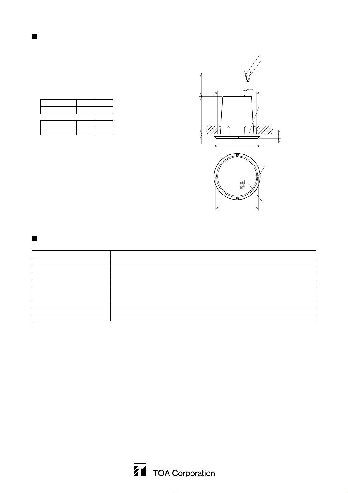
INSTALLATION
1. Make a 98 mm diameter hole in a ceiling. (It is possible to
use the supplied pattern paper for a 98 mm diameter
hole.)
2. Attach the supplied gasket to the panel.
3. Connect the input cable to the speaker cable.
4. Using the four supplied speaker mounting screws (3x16),
secure the speaker to the ceiling.
Caution: Ensure that the ceiling surface is strong
(equivalent to the plywood thicker than 5 mm)
enough to hold the screws.
70 V Line COM HOT
2.5 W (2 kΩ) White Black
100 V Line COM HOT
5 W (2 kΩ) White Black
ø98 mm
(mounting hole diameter)
White (COM)
Gasket
ø116 mm
Punched grille
2 mm 93 mm 330 mm
4 – ø3.5 mm
ø108 mm
SPECIFICATIONS
Rated Input 5 W
Rated Impedance 2 kΩ (100 V Line: 5 W, 70 V Line: 2.5 W)
Output Sound Pressure Level 87 dB (1 W, 1 m)
Frequency Response 150 – 20,000 Hz
Operating Temperature Range -20°C to +55°C
Finish Frame: ABS resin, chrome plating
Punched grille: Stainless steel
Mounting hole diameter 98 mm
Dimensions ø 116 x 110 (d) mm
Weight 620 g
9 mm
Printed in Japan
133-01-343-8C
Note : The design and specifications are subject to change without notice for improvement.
• Accessories
Gasket (chloroprene rubber) .............................. 1
Speaker mounting screw ................................... 4
Pattern paper (ø98 mm hole) ............................. 1
Black
(100 V Line: 5 W, 70 V Line: 2.5 W)
 Loading...