

Page 1

Thank you for purchasing TOA Digital Video Recorder. Please carefully follow the instructions in this
manual to ensure long, trouble-free use of your equipment.
DIGITAL VIDEO
RECORDER
C-DR091 CU Series
C-DR161 CU Series
QUICK MANUAL
Page 2

2
TABLE OF CONTENTS
1. SAFETY PRECAUTIONS .................................................................................. 3
2. NOMENCLATURE AND FUNCTIONS
[ Front ] ....................................................................................................................... 6
[ Rear ] .......................................................................................................................7
3. CONNECTIONS ................................................................................................... 8
4. EXTERNAL TERMINAL CONNECTIONS
4.1. Alarm Input Terminal Connections ..................................................................... 9
4.2. Control I/O Terminal Connections .................................................................... 10
4.3. 10BASE-T/100BASE-TX Terminal Connections .............................................. 10
5. DIGITAL VIDEO RECORDER ACTIVATION
AND TERMINATION
............................................. 11
5.1. Recorder's Activation ....................................................................................... 11
5.2. Recorder's Power Off and Disconnect ............................................................. 11
6. MAIN MENU SETTING
6.1. About the Main Menu Settings ......................................................................... 11
6.2. Setting Item List ............................................................................................... 12
7. INITIAL SETTINGS
7.1. Setting the DVR-ID .......................................................................................... 14
7.2. Clock Settings .................................................................................................. 14
7.3. Hard Disk Initialization ..................................................................................... 15
7.4. Auto-Recording Settings .................................................................................. 16
8. MONITOR DISPLAY
8.1. Full- Screen Display ......................................................................................... 18
8.2. Multi-Segment Split- Screen Display ............................................................... 18
8.3. Sequence Display ............................................................................................ 19
8.4. Zoom Display ................................................................................................... 19
9. RECORDING
9.1. Priority Recording ............................................................................................ 20
9.2. Auto Recording (Alarm Event Recording and Normal Recording) ................... 20
10. PLAYBACK
10.1. Playback .......................................................................................................... 21
10.2. Reverse playback ............................................................................................ 21
10.3. Playback stop ................................................................................................... 21
10.4. Earliest image display ...................................................................................... 21
10.5. Latest image reverse playback ........................................................................ 21
10.6. Fast forward/reverse playback ......................................................................... 21
10.7. Pause ............................................................................................................... 22
10.8. Frame advance/reverse playback .................................................................... 22
10.9. Instance event access ..................................................................................... 22
11. SEARCH
11.1. Date/Time Search ............................................................................................ 23
12. ARCHIVE
12.1. Archiving by Entering the Date and Time ........................................................ 24
13. SPECIFICATIONS ............................................................................................. 25
Page 3
3
1. SAFETY PRECAUTIONS
• Before installation or use, be sure to carefully read all the instructions in this section for correct and safe
operation.
• Make sure to observe the instructions in this manual as the conventions of safety symbols and messages
regarded as very important precautions are included.
• We also recommend you keep this instruction manual handy for future reference.
Safety Symbol and Message Conventions
Safety symbols and messages described below are used in this manual to prevent bodily injury and property
damage which could result from mishandling. Before operating your product, read this manual first and
understand the safety symbols and messages so you are thoroughly aware of the potential safety hazards.
Indicates a potentially hazardous situation which, if mishandled, could
result in death or serious personal injury.
WARNING
When Installing the Unit
• This is a class A product. In a domestic environment this product may cause radio interference in which case
the user may be required to take adequate measures.
• Use the unit only with the voltage specified on the unit. Using a voltage higher than that which is specified
may result in fire or electric shock.
• Do not cut, kink, otherwise damage nor modify the power supply cord. In addition, avoid using the power
cord in close proximity to heaters, and never place heavy objects -- including the unit itself -- on the power
cord, as doing so may result in fire or electric shock.
• Avoid installing or mounting the unit in unstable locations, such as on a rickety table or a slanted surface.
Doing so may result in the unit falling down and causing personal injury and/or property damage.
When the Unit is in Use
• If any of the following irregularities occurs, immediately switch off the power, disconnect the power supply
plug from the AC outlet and inform the shop from where the unit was purchased. Further using the unit may
result in fire or electric shock.
· If you detect smoke or a strange smell coming form the unit
· If water or any metallic object gets into the unit
· If the unit falls, or the unit case breaks
· If the power supply cord is damaged (exposure of the core, disconnection, etc.)
· If no image appears
• To prevent a fire or electric shock, never open the unit case nor modify the unit as there are high voltage
components inside the unit. Refer all servicing to your nearest TOA dealer.
• Do not place cups, bowls, or other containers of liquid or metallic objects on top of the unit. If they
accidentally spill into the unit, this may cause a fire or electric shock.
• Do not insert nor drop metallic objects or flammable materials in the ventilation slots of the unit's cover, as
this may result in fire or electric shock.
• Do not touch the power supply plug or control line during thunder and lightning, as this may result in electric
shock.
• The socket-outlet shall be installed near the equipment and the plug (disconnecting device) shall be easily
accessible.
Do not expose the unit to rain or an environment where it may be
splashed by water or other liquids, as doing so may result in fire or
electric shock.
WARNING
Page 4

4
Indicates a potentially hazardous situation which, if mishandled, could
result in moderate or minor personal injury, and/or property damage.
CAUTION
When Installing the Unit
• Never plug in nor remove the power supply plug with wet hands, as doing so may cause electric shock.
• When unplugging the power supply cord, be sure to grasp the power supply plug; never pull on the cord
itself. Operating the unit with a damaged power supply cord may cause a fire or electric shock.When
removing the power cord, be sure to hold its plug to pull.
• When moving the unit, be sure to remove its power supply cord from the wall outlet. Moving the unit with the
power supply cord connected to the outlet may cause damage to the power supply cord, resulting in fire or
electric shock.
• Do not block the ventilation slots in the unit's cover. Doing so may cause heat to build up inside the unit and
result in fire.
• Avoid installing the unit in humid or dusty locations, in locations exposed to the direct sunlight, near the
heaters, or in locations generating sooty smoke or steam as doing otherwise may result in fire or electric
shock.
• Do not connect a network terminal exposed to excessive voltage to the 100BASE-TX terminal, Disk array
connection terminal or Remote control I/O terminal A, as doing so may result in fire or electric shock.
When the Unit is in Use
• Do not place heavy objects on the unit as this may cause it to fall or break which may result in personal
injury and/or property damage. In addition, the object itself may fall off and cause injury and/or damage.
• Clean the unit periodically. Contact your TOA dealer regarding the cleaning. If dust is allowed to accumulate
in the unit over a long period of time, a fire may result.
• If dust accumulates on the power supply plug or in the wall AC outlet, a fire may result. Clean it periodically.
In addition, insert the plug in the wall outlet securely.
• Switch off the power, and disconnect the power supply plug from the AC outlet when cleaning or leaving the
unit unused for long periods of time. Doing otherwise may cause a fire or electric shock.
• An all-pole mains switch with a contact separation of at least 3 mm in each pole shall be incorporated in the
electrical installation of the building.
The equipment must be connected to an earthed mains socket-outlet.
-Finland
"Laite on liitettävä suojamaadoituskoskettimilla varustettuun pistorasiaan"
-Norway
"Apparatet må tilkoples jordet stikkontakt"
-Sweden
"Apparaten skall anslutas till jordat uttag"
Page 5

5
Note
This equipment has been tested and found to comply with the limits for a Class A digital device,
pursuant to Part 15 of the FCC Rules. These limits are designed to provide reasonable protection
against harmful interference when the equipment is operated in a commercial environment. This
equipment generates, uses, and can radiate radio frequency energy and, if not installed and used in
accordance with the instruction manual, may cause harmful interference to radio communications.
Operation of this equipment in a residential area is likely to cause harmful interference in which case the
user will be required to correct the interference at his own expense.
Modifications
Any modifications made to this device that are not approved by TOA Corporation may void the authority
granted to the user by the FCC to operate this equipment.
CU version complies with Part 15 of the FCC Rules.
This equipment is classified as a LASER CLASS 1 PRODUCT. The following classification label is located on
the drive.
CLASS 1 LASER PRODUCT
CAUTION:
INVISIBLE LASER RADIATION WHEN OPEN.
AVOID EXPOSURE TO BEAM.
Page 6
6
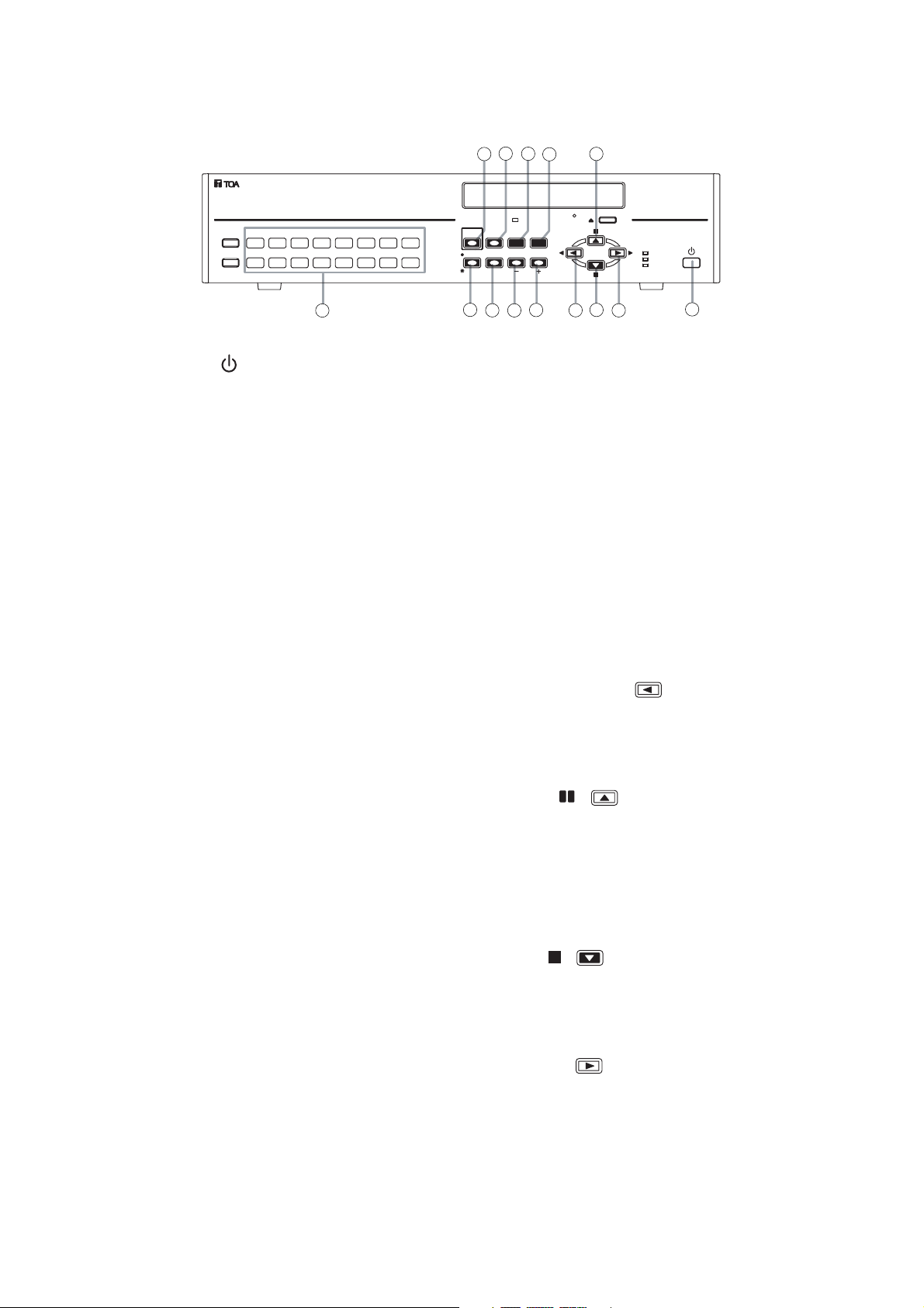
2. NOMENCLATURE AND FUNCTIONS
[ C-DR161 Series Front ]
(1) Power key [ ]
Pressing the Power key changes the Digital
Video Recorder's mode from standby to
operation mode. To switch from operation mode
to standby mode, hold down the Power key for 2
seconds or more.
(2) Camera selector key
Pressing the Camera selector key displays the
corresponding camera image on the full screen.
(3) Priority recording key
Used to start priority recording. To stop priority
recording, hold down the Priority recording key
for 2 seconds or more. The Priority recording
key flashes red during priority recording.
(4) Monitor key
Use this key when switching operation between
Monitor 1 and Monitor 2 outputs.
Monitor 1 output is enabled when the key is
unlit, and Monitor 2 output is enabled when the
key is lit.
(5) Buzzer stop key (Alarm reset key)
Use this key to reset alarm event recording.
This key is also used to stop a buzzer tone.
(6) Zoom key
Use the Zoom key to zoom in on the live and
playback screens (2x zoom).
(7) Search key
Use this key to search for recorded images.
(8) Multi-Screen / [
-
] Key
• Display on the multi-segment split screen.
• Pressing this key while setting values are
selected on the menu screen varies setting
values in the reverse direction.
(9) Menu key
• Holding down the Menu key for 2 seconds or
more when in live mode displays the menu
screen on Monitor 1 screen.
• Use this key when confirming selected setting
items on the menu screen.
• Holding down the Menu key for 2 seconds or
more when the Security setting is activated
displays the Password entry screen.
(10) Sequence/ [ +] Key
• Pressing the Sequence key in live mode
causes the camera outputs to be displayed in
preprogrammed sequential order.
• Pressing the setting value on the Menu screen
during selection changes the setting value in
forward direction.
(11) Reverse playback [ ] key
• Images are played back in reverse if the
Reverse playback key is pressed.
• Use this key to move the cursor to the left on
the menu screen.
(12) Pause [ , ] key
• Use this key to temporarily stop the playback
display. Operation can be performed for the
archive menu display, frame advance/reverse
playback, and instant event access playback
while the display is temporarily stopped.
• Used this key to move the cursor upward on
the Menu screen.
(13) Stop [ , ] key
• Use this key to stop playback or reverse
playback.
• Use this key to move the cursor downward on
the Menu screen.
(14) Playback [ ] key
• Pressing the Playback key plays back
recorded images.
• Use this key to move the cursor to the right on
the Menu screen.
1ARCHIVE
KEY LOCK
1681571461351241131029
5
3
BUZZER STOP/
PRIORITY
ALARM RESET
REC
SEARCH
MONITOR 1 SEQUENCESCREEN
MONITOR 2
MULTI
ZOOM
12
9
7
DVD
MENU/
ENTER
REC
FAILUR E
HD FULL
DIGITAL VIDEO RECORDER C-DR161
2
4
8
6
10
11
13
14
1
Page 7

7
[C-DR161 series Rear]
(15) AC inlet
Connect the supplied power cord to this socket.
(16) Monitor output terminal
• Monitor 1 output terminal
Outputs the Monitor 1's camera images.
• Monitor 2 output terminal
Outputs the Monitor 2's camera images.
(17) Audio input/output terminal
• Audio input terminal
This terminal is used for audio recording.
• Audio output terminal
Outputs audio input terminal signals during live
screen display, and outputs the recorded audio
during playback display.
(18) Video input terminal
Connect the camera to this terminal. Connecting
the camera automatically terminates the Digital
Video Recorder at 75 Ω.
(19) Video output terminal
A loop through output for the Video input
terminal. Connecting the BNC plug to the Video
output terminal automatically cancels the 75Ω
termination.
(20) 10BASE-T/100BASE-TX terminal
Use this terminal to remotely monitor or control
cameras connected to the Digital Video
Recorder or search or play back their recorded
images through the network using the web
browser from a PC.
(21) Alarm input terminal
Use this terminal to make Alarm event
recording. Connect no-voltage contact signals of
sensors, etc. to this terminal.
(22) Control input/output terminal
• Control output terminal
Outputs a signal during equipment failure
occurs.
• Priority recording input terminal
Use this terminal to begin Priority recording
using signals from connected external
equipment.
• Time sync input & output terminal
Use this terminal to synchronize the clocks of
multiple Digital Video Recorders used in the
system.
• Remote Control Input/Output Terminal B
Use this terminal for connection of the CRM1000 Remote Controller.
• Camera control terminal
Use this terminal to control the Combination
Camera.
Note
The C-RM1000 Remote Controller must be
connected to the Digital Video Recorder in
order to control the Combination Camera.
(23) Remote controller input/output terminal A
( Power can be supplied.)
Use this terminal to connect the C-RM1000
Remote Controller.
1
AC MAINS
VIDEO
LINK AUDIOMONITOR OUT RS-232C 100BASE-TX
IN OUT21
23
RM
DISK ARRAY
PRIORITY RM IN-BCAMERA
NC
IN
TERMINATION
ON
OFF
RM IN-A
2
RM OUT-B
---+++GGGG
TIME SYNCCONTROL OUT
OUTIN GG
GGGG4321
SER.
DIGITAL VIDEO RECORDER
model C-DR161D3 CU
110-120V 50/60Hz mA
TOA Corporation
MADE IN JAPAN
IN
1615141312111098765432
1
OUT
ALARM IN
1
GGGGGGGG
GGGGGGGG
1681571461351241131029
15 16
171819
20
21
22
Page 8
8
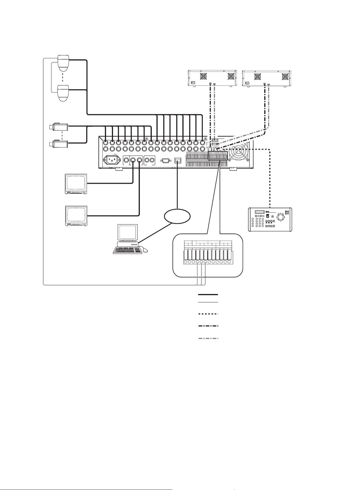
3. CONNECTIONS
Combination camera
2
*
2
*
RS-485
Color camera
Digital Video Recorder
C-DR161 Series
Monitor 1
Live only
Disk Array
C-DA1000-2
DISK
ARRAY
RM
TERMINATION
IN
1
1
AC MAINS
*
LINK AUDIOMONITOR OUT RS-232C 100BASE-TX
MONITOR
OUT1
VIDEO
IN OUT21
MONITOR
OUT2
10BASE-T/
100BASE-TX
1615141312111098765432
RM IN-A
1
2
DISK ARRAY
OUT
ALARM IN
1
RM OUT-B
PRIORITY RM IN-BCAMERA
NC
GGGGGGGG
IN
TIME SYNCCONTROL OUT
GGGGGGGG
1681571461351241131029
OUTIN GG
GGGG4321
ON
OFF
---+++GGGG
Disk Array
C-DA1000-2
RM IN-A
DVR CONTROL
OUTPUT-A
LAN
Monitor 2
PC
RS-485
1
C-DR091 and C-DR161 Series
*
C-DR091: 9 I/ O Terminals
C-DR161: 16 I/ O Terminals
2
Match the Combination Camera’ s address to the Digital Video
*
Recorder’ s video input number.
---
RM OUT-B
GGIN OUT
CAMERA RM IN-BPRIORITY
NC
IN
+++
GGGG
CONTROL OUT TIME SYNC
1234GGGG
CAMERA
+
-
G
: Coaxial cable (Video signal)
: CPEV-S 0.65 (RS-485 Control line)
Twisted pair with shield 22AWG or larger
: Modular cable, 3 m (9.8 ft).
(supplied with the C-RM1000)
: Modular cable, 1 m (3.3 ft)
(supplied with Disk Array)
: eSATA cable, 1 m (3.3 ft)
(supplied with Disk Array)
Remote Controller
C-RM1000
Page 9
9
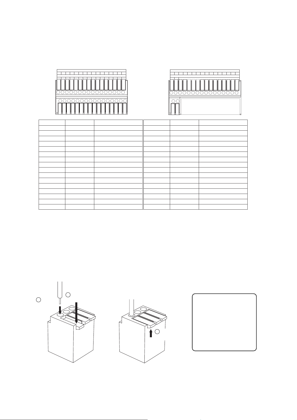
For 16 channel For 9 channel
Applicable cable
• Solid conductor
AWG26 (ø 0.4 mm)
-
AWG16 (ø 1.2 mm)
• Stranded conductor
AWG24 (0.2 mm2)
-
AWG20 (0.75 mm2)
4.1.1. Terminal connection
The terminal connector is unlocked by pressing down on its release button. To connect the cable, press down
on the release button first, insert the cable, then push the release button up again to lock the cable in place.
However, for solid cables with diameters from 0.8 mm(AWG20) to 1.2 mm(AWG16), there is no need to press
down on the release button. Cable can be connected simply by inserting it in place until it will not go any
further.
Note
Ensure that the cable is securely locked into the terminal after connection.
4. EXTERNAL TERMINAL CONNECTIONS
4.1. Alarm Input Terminal Connections
The number of terminals available differs depending on whether the Digital Video Recorder is a 9-channel or a
16-channel version. Refer to the table below when making alarm input terminal connections.
ALARM IN
GGGGGGGG
815714613512411310291
GGGGGGGG
16
G
ALARM IN
GGGGGGGG876543291
Terminal name
1
G
2
G
3
G
4
G
5
G
6
G
7
G
8
G
Symbol
ALARM 1
GND
ALARM 2
GND
ALARM 3
GND
ALARM 4
GND
ALARM 5
GNA
ALARM 6
GND
ALARM 7
GND
ALARM 8
GND
Name
Alarm input 1
Signal ground
Alarm input 2
Signal ground
Alarm input 3
Signal ground
Alarm input 4
Signal ground
Alarm input 5
Signal ground
Alarm input 6
Signal ground
Alarm input 7
Signal ground
Alarm input 8
Signal ground
Terminal name
9
G
10
G
11
G
12
G
13
G
14
G
15
G
16
G
Symbol
ALARM 9
GND
ALARM 10
GND
ALARM 11
GND
ALARM 12
GND
ALARM 13
GNA
ALARM 14
GND
ALARM 15
GND
ALARM 16
GND
Name
Alarm input 9
Signal ground
Alarm input 10
Signal ground
Alarm input 11
Signal ground
Alarm input 12
Signal ground
Alarm input 13
Signal ground
Alarm input 14
Signal ground
Alarm input 15
Signal ground
Alarm input 16
Signal ground
1
Press down the
2
Insert a cable.
Release button.
3
Push the
release button up.
Page 10

10
4.2. Control I/O Terminal Connections
The control input and output terminals include: priority recording terminal, camera control terminal, remote
controller input/output terminals, control output terminal, and time synchronization input/output terminals.
Notes
• Ensure that the cable is securely locked into the terminal after connection.
• Use the CPEV-S cable (twisted pair shielded cable) with diameter larger than 0.65 mm for the Control
Input/Output terminal connections. Also be sure to connect the shielded cable to the GND terminal.
• The maximum cable length of the control cable from the Digital Video Recorder to the camera of which
termination is set to ON is 1.2 km. Also the maximum cable length of the control cable from the Remote
Controller to the Digital Video Recorder of which termination switch is set to ON is 1.2 km.
4.2.1. Time synchronization input/output terminal connections
Two different methods are available to synchronize the time, one using both master and slave units, the other
using NTP.
Note
When using a single-channel Digital Video Recorder, set the synchronization interval to "5 seconds."
To synchronize the times of slave units with the time of the master unit, connect the slave units to the master
unit in a series via their input and output terminals. In other words, connect the input of slave number one to
the master unit's output and the input of slave number two to slave number one's output, and so on.
4.3. 10BASE-T/100BASE-TX Terminal Connections
Use this terminal to remotely monitor or control cameras connected to the Digital Video Recorder, or search or
play back their recorded images on a PC web browser. When connecting a PC directly to the Digital Video
Recorder, use a network crossover cable. Use the straight-through cable for connection between them via a
switching hub.
PRIORITY RM IN-BCAMERA
NC
+
IN
RM OUT-B
++
--
-
GGGG
TIME SYNCCONTROL OUT
OUTIN GG
GGGG4321
A
B
Terminal name
PRIORITY IN
PRIORITY G
NC
CAMERA
CAMERA G
CAMERA
RM IN-B
RM IN-B G
RM IN-B
RM OUT-B
RM OUT-B G
RM OUT-B
A
Name
Priority Recording Input
Priority Recording Ground
Not connected
+
Camera Control (RS-485) +
Camera Control (RS-485) Ground
-
+
Camera Control (RS-485)
Remote Control Input B + (RS-485)
Remote Control Input B Ground
-
Remote Control Input B
+
Remote Control Output B + (RS-485)
-
(RS-485)
Remote Control Output B Ground
-
Remote Control Output B
-
(RS-485)
Terminal name
B
CONTROL OUT 1
CONTROL OUT G
CONTROL OUT 2
CONTROL OUT G
CONTROL OUT 3
CONTROL OUT G
CONTROL OUT 4
CONTROL OUT G
TIME SYNC IN
TIME SYNC G
TIME SYNC OUT
TIME SYNC G
Name
Control Output 1
Control Output Ground
Control Output 2
Control Output Ground
Control Output 3
Control Output Ground
Control Output 4
Control Output Ground
Date/Time Adjustment Input
Date/Time Adjustment Input Ground
Date/Time Adjustment Output
Date/Time Adjustment Output Ground
Master
Input Output
Slave 1
Input Output
Slave 2
Input Output
Input Output
Slave 7
Page 11
11
5. DIGITAL VIDEO RECORDER ACTIVATION AND TERMINATION
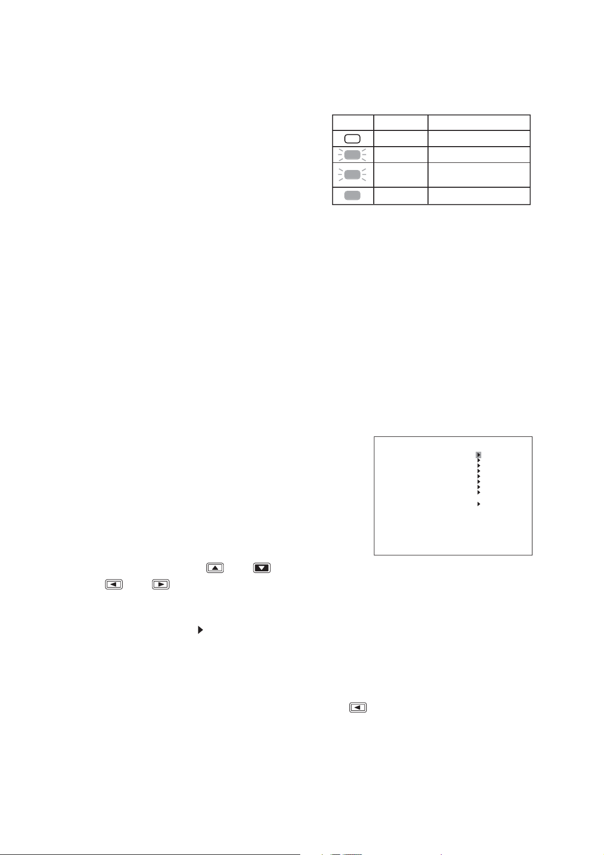
5.1. Recorder's Activation
1. Insert the power supply plug.
The Recorder is placed in standby mode. The power
key flashes at about 5-second intervals while in standby
mode.
Note
Do not pull out the power supply plug while the Power
key is light green. Ensure that the Recorder is in the
standby mode when pulling out the power supply plug.
Logged data could be damaged or lost if the power
supply plug is pulled out during initialization (while
accessing the hard disk).
2. Press the Power key while the Recorder is in standby mode.
The Power key flashes green during a system check. The Power key changes from flashing to steady ON
after system check completion, allowing camera images to be displayed.
5.2. Recorder's Power Off and Disconnect
Hold down the Power key for 2 seconds or more. All operations stop, placing the Recorder in standby mode.
When moving the Recorder, be sure to place it in standby mode, then remove the power supply plug from the
wall outlet.
6. MAIN MENU SETTING
6.1. About the Main Menu Settings
To perform each setting, display the Menu screen when in live mode.
1. Holding down the Menu key for 2 seconds or more.
Displays the Menu screen.
Notes
• Menu screen is not displayed while the Monitor Output 2 is
selected. (while the Monitor key is lit).
• Display the Menu screen after returning to the live mode when
in playback mode.
• Menu screen is not displayed while in zoom mode and during
zoom display (while zoom key is lit)
2. To move the cursor, use the [ ] and [ ] keys.
The [ ] and [ ] keys can be used to move the cursor only when there are setting parameters.
3. To select or change parameters, use the [+] and [–] keys.
4. Press the Menu key at the mark at the desired setting item.
If no change has been made to the current parameter:
The screen moves to the next screen.
If changes have been made:
Save setting confirmation message is displayed. (Refer to the next page.)
5. To exit the setting and return to the previous screen, press the [ ] key at the leftmost parameter position
of the screen.
A Save Setting confirmation dialog is displayed if changes have been made. If set value has not been
changed, the screen moves to the previous screen, Exits the Menu screen when the Main Menu screen is
displayed.
Power key LED indicator
Distinguishes Main power OFF
Flashes (5sec)
Flashes (1sec)
Lights
Mode
Standby mode
During a system check
(during activation)
Power ON (during operation)
MA I N ME NU
REC SE TT ING
DISPLAY SETTING
NETWORK SET T I NG
MA I L S E T T I NG
SYSTEM SETT I NG
LOG D I SPLAY
DATE/TIME SETTING
MA I NT ENANCE
I MAGE ARCH I V I NG
Page 12

12
6.2. Setting Item List
MAIN MENU
Main menu item
REC SETTING
DISPLAY SETTING
NETWORK SETTING
MAIL SETTING
To next page
Menu item Setting item
PRIORITY REC SETTING
AUTO REC SETTING
PRE-REC SETTING
OVERWRITE
CHARCTER DISPLAY SETTING
MONITOR OUTPUT SETTING
SEQUENCE SETTING
CAMERA NAME SETTING
DVR NAME SETTING
MONITOR 1, 2 SCREEN
ALARM DISPLAY INTERVAL
IP ADDRESS
SUBNET MASK
DEFAULT GATEWAY
WEB SERVER PORT
WEB USER PASSWORD
WEB ADMIN PASSWORD
WEB LIVE QUALITY
WEB MAX BIT RATE
PRIMARY DNS
SECONDARY DNS
NTP SERVER
TIME ZONE (GMT
SENDER ADDRESS
SEND-TO ADDRESS 1
SMTP SERVER
POP 3 AUTHENTICATION
ENCRYPTION
ACCOUNT NAME
PASSWORD
POP3 SERVER
TRANSMISSION SETTING
TEST TRANSMISSION
)
-
4
REC SETTING
PRIORITY REC INPUT MODE
AUDIO
POST TIME
SCHEDULE
GROUP A
SPECIAL DAY SETTING
MOTION SETTING
AUDIO
REC TIME
REC RATE
REC QUALITY
AUDIO
REC AUDIO
OVERWRITE
REC
PLAY
REMAINING
DISK MODE
DISK STATUS
DATE
TIME
DATE/ TIME
MONITOR 1 , 2 CAM NAME
DVR NAME
-
F SETTING
NORMAL REC SETTING
ALARM EVENT
REC SETTING
EVENT
ALARM EVENT
REC MODE
ALARM INPUT MODE
POST ALARM TIME
MOTION DETECT MODE
POST MOTION TIME
Page 13

13
To previous page
Main menu item
SYSTEM SETTING
Menu item Setting item
PLAY DISK
HD REMAINING TIME
BUZZER
I/O TERMINAL MODE
CTRL OUT TERMINAL
SECURITY SETTING
CAMERA PRESET SETTING
CAMERA PROTOCOL
CAMERA BIT RATE
RS232C BIT RATE
RS232C FLOW CTRL
RS232C RESPONSE
CONTROLLER BIT RATE
CONTROLLER RESPONSE
DVR-ID
LANGUAGE SELECTION
INPUT MODE
OUTPUT MODE
PRIORITY REC
ALARM REC
MOTION REC
HD FULL
HD ERROR
VIDEO LOSS
FAN FAILURE
OPERATION LEVEL 1, 2, 3
USB KEY LEVEL
PRIORITY REC OPERATION LEVEL 3
REMOTE ACCESS LIMIT
LOGOUT INTERVAL
LOG DISPLAY
DATE/TIME SETTING
MAINTENANCE
IMAGE ARCHIVING
REC LOG
FAILURE LOG
SYSTEM LOG
DATE/TIME SETTING
DATE/TIME ADJUST OPERATE
DATE/TIME ADJUST TIME
DATE/TIME ADJUST OUTPUT
DAYLIGHT SETTING
START DATE/TIME
END DATE/TIME
HD INITIALIZE
SETTING INITIALIZE
LOG INITIALIZE
EXPORT SETTING DATA
IMPORT SETTING DATA
USB KEY REGISTRATION
USB KEY DATA ERASURE
DISK ARRAY 1, 2
START, END 1 - 5
CAMERA 1
-
16 , ALL
DISK MODE
Page 14

14
1. Hold down the Menu key for 2 seconds or more.
The main menu screen is displayed.
2. Move the cursor with the [ ] and [ ] keys to select "DATE/TIME SETTING," then press the Menu
key.
The clock setting screen is displayed.
3. Move the cursor with the [ ] and [ ] keys and perform clock settings using the [+] and [-] keys.
Set year, month, date, hour, minute, and second.
4. Press the [ ] key while the cursor is set to the leftmost selection item on the screen.
The indication will appear to ask whether or not to save the setting.
7. INITIAL SETTINGS
Be sure to perform the following settings before using the Digital Video Recorder. Failure to do so may lead to
incorrect operation of each function.
• DVR-ID setting (When cascade-connecting)
Note: When cascade-connecting the Digital Video Recorders, set the DVR-ID first. Otherwise, the Menu
screen is not displayed.
• Clock settings
• Hard disk initialization
• Auto-Recording settings
7.1. Setting the DVR-ID
When cascade-connecting the Digital Video Recorders, set different DVR-ID for all individual Digital Video
Recorders. DVR-ID are all factory-preset to "1." Follow the procedure below to set DVR number.
1. Press the Digital Video Recorder's Power key while holding down the Sequence key in standby mode.
Camera Selection keys 1 – 8 flashes for about 1minute.
2. Press the desired DVR-ID to set.
The selected number flashes three times, then the number is programmed as DVR-ID.
Note: It is impossible to operate the Digital Video Recorder when the main power is set to OFF. Operate the
Digital Video Recorder after placing it in standby mode.
7.2. Clock Settings
Perform clock settings of the Digital Video Recorder. Adjust the date and time in Clock Settings on the menu screen.
Notes
• If the clock setting is not performed, video recordings are not made according to the schedule set in the
auto-recording setting.
• In some cases, changing the current time may make it impossible to play back the recorded images
correctly when duplicated time data exists in the recording data.
J
A
N
MA I N ME NU
REC SE TT ING
DISPLAY SETTING
NETWORK SET T I NG
MA I L S E T T I NG
SYSTEM SETT I NG
LOG D I SPLAY
DATE/TIME SETTING
MA I NT ENANCE
I MAGE ARCH I V I NG
Menu key
DATE/TIME SETTING
DATE/TIME SETTING
DATE/TIME ADJUST OPERATE SLAVE
DATE/TIME ADJUST TIME 00:00
DATE/ T I ME ADJUST OUTPUT 1SEC
DAYL I GHT SE TT I NG ON
START DATE/ T IME
END DATE / T I ME
JAN / 1 / 05 00 :00 : 00
APR 1ST WEEK SUN 02 : 0 0
OCT LAS T WEE K SUN 0 2 : 0 0
Page 15

15
1. Hold down the Menu key for 2 seconds or more.
The main menu screen is displayed.
2. Move the cursor with the [ ] and [ ] keys to select "MAINTENANCE," then press the Menu key.
The Equipment Maintenance screen is displayed.
3. Select "HD INITIALIZE," then press the Menu key.
The Hard Disk Initialization screen is displayed.
4. Select the disk mode using the [+] and [
-
] keys.
Select "NORMAL," or "MIRROR."
5. Move the cursor with the [ ] and [ ] keys to select "EXECUTE," then press the Menu key.
"YES" and "CANCEL" are displayed.
6. Move the cursor with the [ ] and [ ] keys to select "YES," then press the Menu key.
Confirmation message is displayed after executing the hard disk initialization.
7. Select "OK," then press the Menu key.
The display returns to the hard disk initialization screen.
7.3. Hard Disk Initialization
Set disk mode (normal mode and mirror mode) used for recording to the hard disk to initialize the hard disk.
Notes
• Since initializing the hard disk erases all recorded images, be sure to copy the necessary data to DVD-R
disk or USB memory before initialization.
• Disk mode is factory-preset to "NORMAL." Leave the disk mode as it is when using the Digital Video
Recorder in normal mode. However, it is recommended that the hard disk be initialized since recording
starts automatically when the Digital Video Recorder's power is switched on.
5. Move the cursor with the [ ] and [ ] keys, select "YES," then press the Menu key.
The message requesting a reboot is displayed.
Note
There is no need to reboot the DVR if not synchronizing using the NTP server, though the message
requesting a reboot is displayed after the clock setting has been saved. (The changed setting is reflected in
the device without rebooting the DVR.)
6. Move the cursor with the [ ] and [ ] keys to select "NO," then press the Menu key.
The display reverts to the main menu screen.
MA I NT ENANCE
HD I N I T I AL I ZE
SETT I NG I N I T IAL I ZE EXECUTE
LOG I N I T IAL I ZE EXECUTE
SET DATA ARCH I V I NG EXECUTE
SET DATA READI NG EXECUTE
USB KEY REG I ST RAT I ON EXECUTE
USB KEY DATA ERASURE EX ECUTE
D I SK ARRAY 1 UNUSED
D I SK ARRAY 2 UNUSED
Menu key
HD INIT IALIZE
DISK MODE NORMAL
EXECUTE EXECUTE
HDD–A MASTER 160GB SLAVE
HDD–B MASTER 160GB SLAVE DVD
-----
Page 16

16
1. Hold down the Menu key for 2 seconds or more.
The main menu screen is displayed.
2. Select "REC SETTING," then press the Menu key. The Recording setting screen is displayed.
3. Move the cursor with the [ ] and [ ] keys to select "AUTO REC SETTING," then press the Menu
key.
The Auto-recording setting screen is displayed.
4. Select "SCHEDULE," then press the Menu key.
5. Move the cursor with the [ ], [ ], [ ], and [ ] keys and perform schedule setting using the [+]
and [-] keys.
Set a day of the week, Start time, End time and manner of operation (group setting).
6. Press the [ ] key while the cursor is set to the leftmost selection item on the screen.
The indication will appear to ask whether or not to save the setting.
7. Move the cursor with the [ ] and [ ] keys to select "YES," then press the Menu key.
The display reverts to the auto-recording setting screen.
7.4. Auto-Recording Settings
Recordings are normally performed according to the preprogrammed schedule. Therefore, perform schedule
or group settings when making auto-recording.
7.4.1. Schedule setting
Set the schedule (Day, Start time, and End time) for each group to operate.
Menu key Menu key
Page 17

17
7.4.2. Setting the group
Perform individual settings such as Normal recording and Alarm Event recording for Group A - F.
1. Choose "Group A-F" from the Auto-recording Settings and press the Menu key.
The Group setting screen is displayed.
2. Move the cursor with the [ ], [ ], [ ], and [ ] keys and perform Group setting using the [+]
and [-] keys.
3. Press the [ ] key while the cursor is set to the leftmost selection item on the screen.
The indication will appear to ask whether or not to save the setting.
4. Move the cursor with the [ ] and [ ] keys to select "YES," then press the Menu key.
The display reverts to the auto-recording setting screen.
7.4.3. Other settings
In Auto-Recording Settings, "special day," "motion detection," and "audio (ON/OFF)" settings can be
performed in addition to both schedule and group settings.
AUTO REC SET T I NG
SCHEDULE
GROUP –A S ET T I NG
GROUP –B S ET T I NG
GROUP –C S ET T I NG
GROUP –D S ET T I NG
GROUP –E SE TT I NG
GROUP – F SE T T I NG
SPECI AL DAY SET T I NG
MOT I ON S E T T I NG
AUD I O ON
Menu key
GROUP –A S ET T I NG
NORMAL RE C SE T T I NG
ALARM EVENT REC SETT ING
ALARM EVENT REC MODE SEQUENCE
ALARM I NPUT MODE EDGE
POST ALARM TIME 999SEC
MOTI ON DETECT MODE LEVE L
POST MOTION TIME 1SEC
Page 18

18
8. MONITOR DISPLAY
8.1. Full-Screen Display
Pressing the Camera Selector key while in live or playback mode displays the selected camera output on the
full screen.
8.2. Multi-Segment Split-Screen Display
When the live or playback screen is displayed, the multi-segment split-screen display changes as shown
below each time the Multi-Screen key is pressed. Multi-Screen key lights continuously during multi-Segment
Split-Screen display.
L1 L2 L3
L4 L5 L6
L7 L8 L9
SAT JAN / 0 1 / 0 5
0:00:00
Press the Camera
Selector key No. 3.
AB
L3
SAT JAN / 0 1 / 0 5
0:00:00
AB
9-channel DVR :
4 Seg A 4 Seg B
9 Seg 4 Seg C
4 Seg A 4 Seg B 4 Seg C 4 Seg D
16 Seg 9 Seg B 9 Seg A
16-channel DVR:
(Example) Screen display in live mode (9-channel DVR)
4-segment split A
L1 L2
L3 L4
L1 L2 L3
L4 L5 L6
L7 L8 L9
SAT JAN / 0 1 / 0 5
0:00:00
Press the
Multi-Screen key.
SAT JAN / 0 1 / 0 5
0:00:00
Press the
Multi-Screen key.
AB
Press the
Multi-Screen key.
AB
4-segment split B
L5 L6
L7 L8
4-segment split C9-segment split
L9 L1
L2 L3
SAT JAN / 0 1 / 0 5
0:00:00
Press the
Multi-Screen key.
SAT JAN / 0 1 / 0 5
0:00:00
AB
AB
Page 19

19
(Setting Example)
Step 1 : Camera 1 3 seconds
Step 2 : Camera 2 3 seconds
Step 3 : Camera 3 3 seconds
Step 4 : 4-split A 3 seconds
Note
That when the screen is switched, the
picture may be distorted momentarily.
1. Press the zoom key
The zoom selection screen is displayed. The pointer is displayed on the screen.
2. Move the central point of the subject to be zoomed using the [ ], [ ], [ ], and [ ] keys, then
press the Menu key.
The subject can be zoomed with the designated point at the center. Zoomed areas can be moved using the
[ ], [ ], [ ], and [ ] keys even while zoomed.
3. Press the Menu key when the zoom screen is displayed.
The display reverts to the zoom selection screen. Pressing the Zoom key again when the zoom screen is
displayed resets the zoom display.
Note
When channels are changed, multi-segment split-screen display is selected, or a search function is operated
during zoom display, the zoom mode is reset.
8.3. Sequence Display
Camera live images are displayed in sequential order when the Sequence key is pressed while in live mode.
Viewing intervals and cameras to be displayed can be set on the menu screen. Sequence key lights
continuously during Sequence display.
8.4. Zoom Display
Live or recorded full-screen images can be viewed in 2 x zoom display. Zoom key lights continuously while the
Zoom selection screen or Zoom screen is displayed.
Step 1
L1
SAT JAN/ 0 1 / 05
0:00:00
3 seconds elaps
Step 2
L2
SAT JAN/ 0 1 / 05
0:00:00
AB
Step 4
L1 L2
L3 L4
3 seconds elaps
SAT JAN/ 0 1 / 05
0:00:00
AB
Step 3
L3
3 seconds elaps
3 seconds elaps
SAT JAN/ 0 1 / 05
0:00:00
AB
AB
Live or play back screen
Zoom key
Zoom key
Zoom selection screen Zoom screen
Menu key
Menu key
Zoom key
Page 20

20
9. RECORDING
9.1. Priority Recording
Priority recording is given higher priority over Auto recording. Use this recording mode to check recording
details when, for example, a suspicious person intrudes or when making recording outside the scheduled time
period. In the Priority Recording settings, the following settings can be made for individual cameras: recording
ON/OFF, recording rate, picture quality and audio ON/OFF.
9.1.1. How to perform priority recording
1. Press the Priority Recording key to start the priority recording. To stop a buzzer sound, press the Buzzer
Stop key.
2. Hold down the Priority Recording key for 2 seconds or more to terminate the priority recording.
9.2. Auto Recording (Alarm Event Recording and Normal Recording)
With auto-recording, recordings are made according to a preset schedule, which can include up to twelve
different programs. If one or more programs have duplicate execution times, the program with a largest
number takes precedence. Settable items for each program include: Day of the Week; Start/End Times; and
Operation. Up to six settings groups, named A through F, can be made for "Operation," and recording settings
for Normal and Alarm recording can also be registered. Further, up to sixty "special day" operational settings
can also be made, with operation controlled by different programs, motion detection areas for individual
cameras, and audio recording during auto- recording.
9.2.1. Alarm event recording
Alarm Event recording includes both "Alarm Input" and "Motion Detection" recording. For Alarm Event
recording, settable items for each individual camera include: Recording ON/OFF; Recording Rate; and Picture
Quality. It is also possible to set, for each recording mode, the type of events that will cause recording to
begin.
For Alarm Event recording mode, it is possible to set the type of recording operation to be performed when
multiple events have occurred simultaneously. Setting the mode to "Sequence" allows two or more events to
be set for individual cameras. For Alarm Input recording time, set both alarm input mode and post alarm time
intervals. For Motion Detection, set both motion detection mode and post-motion alarm time.
When an alarm event occurs, the corresponding camera's image is switched to full-screen display until the
preset alarm time interval has elapsed, after which the display reverts to the original screen display.
Alarm input recording: Alarm Input recording begins when signals are received at the alarm input
terminal on the rear panel. Use event settings to set cameras to be recorded. If
"Sequence" is selected, up to four alarm input terminals can be set optionally
per camera. If "Last" is selected, the "Alarm ON/OFF" can be set only for the
alarm input terminal with a number corresponding to that of the camera.
motion detected recording: Motion Detection recording begins when motion is detected in a camera image.
Use Motion Settings to set the motion detection area, sensitivity, and activation.
Use event settings to set cameras to be recorded. If "Sequence" is selected as
the alarm event recording mode, then up to four alarm input terminals can be
set optionally per camera. If "Last" is selected, the "Alarm ON/OFF" can be set
only for the alarm input terminal with a number corresponding to that of the
camera.
9.2.2. Normal recording
This function automatically records camera images set by schedule. For Normal recording, settable items for
each individual camera include: Recording ON/OFF; Recording Rate; and Picture Quality. (Refer to p. 81;
Normal Recording setting.) Recordings can be made on scheduled patterns like "day and night," and
"weekdays and holidays" by combining two or more programs.
Page 21

21
10. PLAYBACK
10.1. Playback
Press the Play [ ] key.
Recorded images are played back. The Playback key lights green, displaying the playback screen.
When playback is performed again, playback begins from the time at which it last stopped.
10.2. Reverse playback
Press the Reverse Play [ ] key.
Plays back recorded images in reverse chronological order. The Reverse Play key lights green, displaying the
reverse playback screen.
When reverse playback is performed again, it begins from the time at which it last stopped.
10.3. Playback stop
Press the Stop [ ] key
Stops pictures being played back. Stopping the playback switches the display to the live mode.
10.4. Earliest image display
Press the Play [ ] key while holding down the Playback Stop [ ] key.
Playback begins from the time at which the earliest image was recorded.
10.5. Latest image reverse playback
Press the Reverse Play [ ] key while holding down the Playback Stop [ ] key.
Reverse playback begins from the time at which the latest image was recorded.
10.6. Fast forward/reverse playback
Press the Play [ ]] key (Reverse Play [ ] key when in reverse playback mode) during playback.
Fast forward playback (fast reverse playback when in reverse playback mode) is initiated. Playback speed
cycles through 2X, 4X and 8X whenever the key is pressed. The speed can be increased using the 1-minute
or 10-minute time skip function.
Notes
• The 1-minute/10-minute skip function may not operate correctly if recordings are made with the clock turned
back.
• Recorded images may not be played back at the indicated speed depending on the hard disk access time,
etc.
• For the pre-recorded recording data, it cannot playback skips forward in 1-minute/10-minute segments.
( )
( )
( )
Playback speed
Normal speed 2 times (X2) 4 times (X4) 8 times (X8)
10-minute time skip (X10 minute) 1-minute time skip (X 1 minute)
Page 22

22
10.7. Pause
1. Press the Pause [ ] ( ) key during forward or reverse playback.
Playback is temporarily stopped and the key lights green.
2. To perform playback again, press the Play [ ] key or Reverse Play [ ] key.
Pause mode is cancelled and forward or reverse playback begins again.
10.8. Frame advance/reverse playback
Press the Play [ ] key or Reverse Play [ ] key with the Pause [ ] ( ) key pressed, while
recording is temporarily stopped ,
Frame advance or reverse playback is performed per screen whenever the key is pressed.
10.9. Instance event access
Recording moves to the event start time (Priority recording, Alarm Event recording or Normal recording) and
temporarily stops. Playback images can be moved from event to event and required images can be quickly
searched
[Instant access to the next event]
Hold down the Play [ ] key for 2 seconds or more while playback is temporarily stopped.
Playback advances to the beginning of the next event and temporarily stops.
[Instant access to the previous event]
Hold down the Reverse Play [ ] key for 2 seconds or more while playback is temporarily stopped.
Playback advances to the beginning of the current event and temporarily stops.
Page 23

23
FEB
1. Press the Search key.
The Search screen is displayed.
2. Select "DATE/TIME SEARCH," press the Menu key.
Date/Time search screen is displayed.
3. Move the cursor with the [ ] and [ ] keys and perform
clock settings using the [+] and [-] keys. Set year, month,
date, hour, minute, and second.
4. Move the cursor to "EXECUTE" and press the Menu key.
Images recorded at the time closest to the designated time
are displayed.
11. SEARCH
11.1. Date/Time Search
Entering the date and time to perform a search displays all camera images recorded closest to the designated
time in freeze-frame on the 16-segment (or 9-segment) split screen display. If no recording is made on the
designated date and time, the date and time closest after the designated date and time is displayed. The
oldest and newest times for recorded data are displayed, so please enter dates and times occurring between
these.
An error message is displayed at upper right of the screen if
images does not exist after the designated time.
Pressing the Menu key moves the cursor to the previous
position.
DATE/TIME SEARCH
DATE/TIME FEB/24/05 05:00:00
SEARCH EXECUTE
REC START FEB/24 / 05 05 : 00: 00
REC END FEB/25 / 05 05 : 00: 00
SEARCH SCRE EN D I SP LAY T IME
FEB /24 / 05 05: 00 :00
NOTHING FOUND OK
Page 24

24
12. ARCHIVE
The Digital Video Recorder is equipped with an archive function that transfers image data recorded on the
hard disk to DVD-R disk (available only to models with DVD drives) or USB memory. Camera image data
designated between start position and end position can be archived. Since dedicated viewer software is also
downloaded at the same time, archived images can be easily played back on a PC.
Note
Archive operation can be performed only at the operation level 1. When the security has been set, perform
archive operation after login to the Operation Level 1.
12.1. Archiving by Entering the Date and Time
Use this method for archiving when the date and time are known. Insert the DVD to be archived into the
Digital Video Recorder or connect the USB flash memory to the Digital Video Recorder;
USB: Archive to the USB memory
DVD: Archive to the DVD-R
Cancel: Reverts to the previous cursor
position without executing.
FEB
/07
/
:01
:
0
1. Hold down the Menu key for 2 seconds or more.
Menu screen is displayed.
2. Move the cursor with the [ ] and [ ] keys, select
"IMAGE ARCHIVING," and press the Menu key.
Image archive screen is displayed.
3. Using the [+] and [-] keys, enter the time and date for Start
1 and End 1.
4. To continue to archive other data, repeat Step 3.
Up to 5 start and end "dates and times" can be set.
Note
A separate folder is created at the destination to be
archived each time archiving starts and ends. Perform
archiving by shifting time even when archiving for
consecutive time. Dividing folders results in fewer files in
each folder, thereby making search and display faster.
5. Move the cursor with the [ ] and [ ]keys and
perform camera setting using the [+] and [
-
] keys.
Select the camera to be archived from "CAMERA 1-9" and
"ALL." (For 16 channels, up to camera 16 can be selected.
)
6. Move the cursor using the [ ] and [ ] keys, select
"EXECUTE," and then press the Menu key.
A message box for selection of either USB or DVD is
displayed at the upper right of the screen. (model with DVD
drive only)
For the model without DVD drive, Selection message "Yes"
or "Cancel" is displayed.
7. Move the cursor using the [ ] and [ ] keys, select
"USB" or "DVD," and then press the Menu key.
For the model without DVD drive, select "YES," then press
the Menu key.
I MAGE ARCH I V I NG
START POS1 FEB/07 / 05 12 : 01: 00
END POS1 FEB / 07/ 05 13: 02 :00
START POS2 FEB/07 / 05 12 : 03: 00
END POS2 FEB / 07/ 05 13: 04 :00
START POS3 FEB/07 / 05 12 : 05: 00
END POS3 FEB / 07/ 05 13: 06 :00
START POS4 FEB/07 / 05 12 : 07: 00
END POS4 FEB / 07/ 05 13: 08 :00
START POS5 FEB/07 / 05 12 : 09: 00
END POS5 FEB / 07/ 05 13: 10 :00
CAMERA CAMERA3
TRANS FER E XECUT E
REC S TART F EB / 0 1 / 0 5 8 : 0 0 : 0 0
REC END FEB / 2 0 / 0 5 1 7 : 3
0 512
EXECUTE?
USB DVD CANCEL
0
0:00
Page 25

25
13. SPECIFICATIONS
C-DR091-08 C-DR091-1 C-DR091-3 C-DR091-6
110 – 120 V AC 50/60 Hz
400 mA 410 mA 480 mA 530 mA
Motion-JPEG
NTSC
E-IDE Hard Disk E-IDE Hard Disk E-IDE Hard Disk E-IDE Hard Disk
80 GB (80 GB x 1)
160 GB (160 GB x 1) 320 GB (160 GB x 2) 600 GB (300 GB x 2)
9 channels, VBS1.0 V(p-p), 75 Ω, BNC
9 channels, VBS1.0V(p-p), 75 Ω, BNC, loop-through
2 channels, VBS1.0V(p-p), 75 Ω, BNC,
1 channel is dedicated to real-time image (Full-screen and 4-segment split screen display
only. Nothing is displayed other than camera names and camera numbers.)
1 channel, VBS1.0V(p-p), 75 Ω, BNC, Connect the monitor output of other digital video recorder
(C-DR091/161 series) to this terminal. Multiple digital video recorders can be operated and
monitored with a single monitor by using the C-RM1000 Remote Controller (option).
8 bits, Linear PCM, sampling frequency: 16 kHz
1 channel, –10 dB*, 10 kΩ, unbalanced, RCA pin jack
1 channel, –10 dB*, 600 Ω, unbalanced, RCA pin jack
1-, 4-, 9-, segment screen sequence, electronic 2 x zoom
Changeable in 5 steps, (File size: 16 - 64KB) 64 KB (Quality 1), 40 KB (Quality 2),
32 KB (Quality 3), 24 KB (Quality 4), 16 KB (Quality 5)
720 x 240 pixels
Total recording rate 120 IPS (each camera can be individually set for the following rate)
120, 60, 30, 15, 8, 4, 2, 1, 1/2, 1/3, 1/5, 1/10, 1/20, 1/30, 1/60 IPS
Max. 5 min (0 - 300 s)
Max. 999 s (0 - 999 s), non-limit
Year/ month/ date/ hour/ minute/ second, 24-hours format display,
monthly deviation of within ±30 s (25°C (77°F)), can be operated until the year 2099
5 Sensitivity levels, can be turned on/off for individual areas
Date/Time search, Event search (Priority recording, Alarm-input recording,
Normal recording, Motion detect recording, all)
9 channels (EDGE, LEVEL), no-voltage make contact input, open voltage: 2 V DC,
short-circuit current: 1.5 mA, minimum short-circuit time: over 100 ms,
loop resistance: under 100 Ω, screwless connector
4 channels (can be set for Priority recording, Alarm-input recording, Motion detect
recording, Video loss, HD Full, Fan Failure, and HD Error) open collector output,
withstand voltage: 30 V DC, control current : 20 mA, screwless connector
1 channel, no-voltage make contact input, open voltage: 2 V DC, short-circuit current: 1.5 mA,
minimum short-circuit time: over 100 ms, loop resistance: under 100 Ω, screwless connector
1 channel, no-voltage make contact input, open voltage: 2 V DC, short-circuit current: 1.5 mA,
minimum short-circuit time: over 100 ms, loop resistance: under 100 Ω, screwless connector
1 channel, open collector output, withstand voltage: 30 V DC,
control current: 20 mA, screwless connector
1 channel, RS-485, screwless connector
1 channels, RS-485, screwless connector or RJ11
2 channels, eSATA (and dedicated control signal), eSATA connector and modular connector
RS-232C : D-sub connector (9 pin, male), 10 BASE-T/100 BASE-TX ethernet : RJ45
mail transmission capability, USB terminals (ARCHIVE, KEY LOCK), Web function (Realtime image, play-back, remote, menu), Language choice (English/ French/ Japanese)
Under 3,000 m (9,843 ft) (relative to sea level)
+5°C to +40°C (41°F to 104°F) (+5°C to +35°C (41°F to 95°F) when mounted on a rack)
Under 80% RH (no condensation)
Panel: Surface-treated steel plate, black, paint, 30% gloss
Case: Pre-coated steel plate, black
420 (W) x 93.9 (H) x 332.8 (D) mm (16.5 (W) x 3.7 (H) x 13.1 (D) inch)
5.7 kg (12.6 lb) 5.7 kg (12.6 lb) 6.5 kg (14.3 lb) 6.5 kg (14.3 lb)
Power supply cord (2 m (6.6 ft)) … 1
Rack mounting bracket: MB-23B
Model
Power Source
Power Consumption
Image Compression
Video Format
Recording Medium
Video Input
Video Output
Monitor Output
Link Input
Audio Recording System
Audio Input
Audio Output
Screen Display
Picture Quality
Pixels
Recording Rate
Pre-Recording
Post Alarm Recording
Date/Time
Motion Detect
Search Function
Alarm Input
Control Output
Priority Recording Input
Time Synchronization
Input
Time Synchronization
Output
Camera Control
Remote Control
Disk Array
Communication Function
Other Function
Altitude
Operating Temperature
Operating Humidity
Finish
Dimensions
Weight
Accessory
Option
* 0 dB = 1V
Note: The design and specifications are subject to change without notice for improvement.
Page 26

26
C-DR161-08 C-DR161-1 C-DR161-3 C-DR161-6
110 – 120 V AC 50/60 Hz
430 mA 440 mA 540 mA 560 mA
Motion-JPEG
NTSC
E-IDE Hard Disk E-IDE Hard Disk E-IDE Hard Disk E-IDE Hard Disk
80 GB (80 GB x 1)
160 GB (160 GB x 1) 320 GB (160 GB x 2) 600 GB (300 GB x 2)
16 channels, VBS1.0 V(p-p), 75 Ω, BNC
16 channels, VBS1.0V(p-p), 75 Ω, BNC, loop-through
2 channels, VBS1.0V(p-p), 75 Ω, BNC,
1 channel is dedicated to real-time image (Full-screen and 4-segment split screen display
only. Nothing is displayed other than camera names and camera numbers.)
1 channel, VBS1.0V(p-p), 75Ω, BNC, Connect the monitor output of other digital video recorder
(C-DR091/161 series) to this terminal. Multiple digital video recorders can be operated and
monitored with a single monitor by using the C-RM1000 Remote Controller (option).
8 bits, Linear PCM, sampling frequency: 16 kHz
1 channel, –10 dB*, 10 kΩ, unbalanced, RCA pin jack
1 channel, –10 dB*, 600 Ω, unbalanced, RCA pin jack
1-, 4-, 9-, 16-, segment screen sequence, electronic 2 x zoom
Changeable in 5 steps, (File size: 16 - 64KB) 64 KB (Quality 1), 40 KB (Quality 2),
32 KB (Quality 3), 24 KB (Quality 4), 16 KB (Quality 5)
720 x 240 pixels
Total recording rate 120 IPS (each camera can be individually set for the following rate)
120, 60, 30, 15, 8, 4, 2, 1, 1/2, 1/3, 1/5, 1/10, 1/20, 1/30, 1/60 IPS
Max. 5 min (0 - 300 s)
Max. 999 s (0 - 999 s), non-limit
Year/ month/ date/ hour/ minute/ second, 24-hours format display,
monthly deviation of within ±30 s (25°C (77°F)), can be operated until the year 2099
5 Sensitivity levels, can be turned on/off for individual areas
Date/Time search, Event search (Priority recording, Alarm-input recording,
Normal recording, Motion detect recording, all)
16 channels (EDGE, LEVEL), no-voltage make contact input, open voltage: 2 V DC,
short-circuit current: 1.5 mA, minimum short-circuit time: over 100 ms,
loop resistance: under 100 Ω, screwless connector
4 channels (can be set for Priority recording, Alarm-input recording, Motion detect recording
Video loss, HD Full, Fan Failure, and HD Error) open collector output,
withstand voltage: 30 V DC, control current : 20 mA, screwless connector
1 channel, no-voltage make contact input, open voltage: 2 V DC, short-circuit current: 1.5 mA,
minimum short-circuit time: over 100 ms, loop resistance: under 100 Ω, screwless connector
1 channel, no-voltage make contact input, open voltage: 2 V DC, short-circuit current: 1.5 mA,
minimum short-circuit time: over 100 ms, loop resistance: under 100 Ω, screwless connector
1 channel, open collector output, withstand voltage: 30 V DC,
control current: 20 mA, screwless connector
1 channel, RS-485, screwless connector
1 channels, RS-485, screwless connector or RJ11
2 channels, eSATA (and dedicated control signal), eSATA connector and modular connector
RS-232C : D-sub connector (9 pin, male), 10 BASE-T/100 BASE-TX ethernet : RJ45
mail transmission capability, USB terminals (ARCHIVE, KEY LOCK), Web function (Realtime image, play-back, remote, menu), Language choice (English/ French/ Japanese)
Under 3,000 m (9,843 ft) (relative to sea level)
+5°C to +40°C (41°F to 104°F) (+5°C to +35°C (41°F to 95°F) when mounted on a rack)
Under 80% RH (no condensation)
Panel: Surface-treated steel plate, black, paint, 30% gloss
Case: Pre-coated steel plate, black
420 (W) x 93.9 (H) x 332.8 (D) mm (16.5 (W) x 3.7 (H) x 13.1 (D) inch)
5.8 kg (12.8 lb) 5.8 kg (12.8 lb) 6.6 kg (14.6 lb) 6.6 kg (14.6 lb)
Power supply cord (2 m (6.6 ft)) … 1
Rack mounting bracket: MB-23B
Model
Power Source
Power Consumption
Image Compression
Video Format
Recording Medium
Video Input
Video Output
Monitor Output
Link Input
Audio Recording System
Audio Input
Audio Output
Screen Display
Picture Quality
Pixels
Recording Rate
Pre-Recording
Post Alarm Recording
Date/Time
Motion Detect
Search Function
Alarm Input
Control Output
Priority Recording Input
Time Synchronization
Input
Time Synchronization
Output
Camera Control
Remote Control
Disk Array
Communication Function
Other Function
Altitude
Operating Temperature
Operating Humidity
Finish
Dimensions
Weight
Accessory
Option
* 0 dB = 1V
Note: The design and specifications are subject to change without notice for improvement.
Page 27

27
C-DR091D08 C-DR091D1 C-DR091D3 C-DR091D6
110 – 120 V AC 50/60 Hz
490 mA 500 mA 570 mA 590 mA
Motion-JPEG
NTSC
E-IDE Hard Disk E-IDE Hard Disk E-IDE Hard Disk E-IDE Hard Disk
80 GB (80 GB x 1)
160 GB (160 GB x 1) 320 GB (160 GB x 2) 600 GB (300 GB x 2)
9 channels, VBS1.0 V(p-p), 75 Ω, BNC
9 channels, VBS1.0V(p-p), 75 Ω, BNC, loop-through
2 channels, VBS1.0V(p-p), 75 Ω, BNC,
1 channel is dedicated to real-time image (Full-screen and 4-segment split screen display
only. Nothing is displayed other than camera names and camera numbers.)
1 channel, VBS1.0V(p-p), 75 Ω, BNC, Connect the monitor output of other digital video
recorder (C-DR091/161 series) to this terminal. Multiple digital video recorders can be operated
and monitored with a single monitor by using the C-RM1000 Remote Controller (option).
8 bits, Linear PCM, sampling frequency: 16 kHz
1 channel, –10 dB*, 10 kΩ, unbalanced, RCA pin jack
1 channel, –10 dB*, 600 Ω, unbalanced, RCA pin jack
1-, 4-, 9-, segment screen sequence, electronic 2 x zoom
Changeable in 5 steps, (File size: 16 - 64KB) 64 KB (Quality 1), 40 KB (Quality 2),
32 KB (Quality 3), 24 KB (Quality 4), 16 KB (Quality 5)
720 x 240 pixels
Total recording rate 120 IPS (each camera can be individually set for the following rate)
120, 60, 30, 15, 8, 4, 2, 1, 1/2, 1/3, 1/5, 1/10, 1/20, 1/30, 1/60 IPS
Max. 5 min (0 - 300 s)
Max. 999 s (0 - 999 s), non-limit
Year/ month/ date/ hour/ minute/ second, 24-hours format display,
monthly deviation of within ±30 s (25°C (77°F)), can be operated until the year 2099
5 Sensitivity levels, can be turned on/off for individual areas
Date/Time search, Event search (Priority recording, Alarm-input recording,
Normal recording, Motion detect recording, all)
9 channels (EDGE, LEVEL), no-voltage make contact input, open voltage: 2 V DC,
short-circuit current: 1.5 mA, minimum short-circuit time: over 100 ms,
loop resistance: under 100 Ω, screwless connector
4 channels (can be set for Priority recording, Alarm-input recording, Motion detect
recording, Video loss, HD Full, Fan Failure, and HD Error) open collector output,
withstand voltage: 30 V DC, control current : 20 mA, screwless connector
1 channel, no-voltage make contact input, open voltage: 2 V DC, short-circuit current: 1.5 mA,
minimum short-circuit time: over 100 ms, loop resistance: under 100 Ω, screwless connector
1 channel, no-voltage make contact input, open voltage: 2 V DC, short-circuit current: 1.5 mA,
minimum short-circuit time: over 100 ms, loop resistance: under 100 Ω, screwless connector
1 channel, open collector output, withstand voltage: 30 V DC,
control current: 20 mA, screwless connector
1 channel, RS-485, screwless connector
1 channels, RS-485, screwless connector or RJ11
2 channels, eSATA (and dedicated control signal), eSATA connector and modular connector
RS-232C : D-sub connector (9 pin, male), 10 BASE-T/100 BASE-TX ethernet : RJ45
mail transmission capability, USB terminals (ARCHIVE, KEY LOCK), Web function (Realtime image, play-back, remote, menu) ,Language choice (English/ French/ Japanese)
DVD-R
Under 3,000 m (9,843 ft) (relative to sea level)
+5°C to +40°C (41°F to 104°F) (+5°C to +35°C (41°F to 95°F) when mounted on a rack)
Under 80% RH (no condensation)
Panel: Surface-treated steel plate, black, paint, 30% gloss
Case: Pre-coated steel plate, black
420 (W) x 93.9 (H) x 332.8 (D) mm (16.5 (W) x 3.7 (H) x 13.1 (D) inch)
6.8 kg (15.0 lb) 6.8 kg (15.0 lb) 7.6 kg (16.8 lb) 7.6 kg (16.8 lb)
Power supply cord (2 m (6.6 ft)) … 1
Rack mounting bracket: MB-23B
Model
Power Source
Power Consumption
Image Compression
Video Format
Recording Medium
Video Input
Video Output
Monitor Output
Link Input
Audio Recording System
Audio Input
Audio Output
Screen Display
Picture Quality
Pixels
Recording Rate
Pre-Recording
Post Alarm Recording
Date/Time
Motion Detect
Search Function
Alarm Input
Control Output
Priority Recording Input
Time Synchronization
Input
Time Synchronization
Output
Camera Control
Remote Control
Disk Array
Communication Function
Other Function
Applicable DVD Medium
Altitude
Operating Temperature
Operating Humidity
Finish
Dimensions
Weight
Accessory
Option
* 0 dB = 1V
Note: The design and specifications are subject to change without notice for improvement.
Page 28

133-22-062-5C
C-DR161D08 C-DR161D1 C-DR161D3 C-DR161D6
110 – 120 V AC 50/60 Hz
530 mA 530 mA 610 mA 630 mA
Motion-JPEG
NTSC
E-IDE Hard Disk E-IDE Hard Disk E-IDE Hard Disk E-IDE Hard Disk
80 GB (80 GB x 1)
160 GB (160 GB x 1) 320 GB (160 GB x 2) 600 GB (300 GB x 2)
16 channels, VBS1.0 V(p-p), 75 Ω, BNC
16 channels, VBS1.0V(p-p), 75 Ω, BNC, loop-through
2 channels, VBS1.0V(p-p), 75 Ω, BNC,
1 channel is dedicated to real-time image (Full-screen and 4-segment split screen display
only. Nothing is displayed other than camera names and camera numbers.)
1 channel, VBS1.0V(p-p), 75 Ω, BNC, Connect the monitor output of other digital video
recorder (C-DR091/161 series) to this terminal. Multiple digital video recorders can be operated
and monitored with a single monitor by using the C-RM1000 Remote Controller (option).
8 bits, Linear PCM, sampling frequency: 16 kHz
1 channel, –10 dB*, 10 kΩ, unbalanced, RCA pin jack
1 channel, –10 dB*, 600 Ω, unbalanced, RCA pin jack
1-, 4-, 9-, 16-, segment screen sequence, electronic 2 x zoom
Changeable in 5 steps, (File size: 16 - 64KB) 64 KB (Quality 1), 40 KB (Quality 2),
32 KB (Quality 3), 24 KB (Quality 4), 16 KB (Quality 5)
720 x 240 pixels
Total recording rate 120 IPS (each camera can be individually set for the following rate)
120, 60, 30, 15, 8, 4, 2, 1, 1/2, 1/3, 1/5, 1/10, 1/20, 1/30, 1/60 IPS
Max. 5 min (0 - 300 s)
Max. 999 s (0 - 999 s), non-limit
Year/ month/ date/ hour/ minute/ second, 24-hours format display,
monthly deviation of within ±30 s (25°C (77°F)), can be operated until the year 2099
5 Sensitivity levels, can be turned on/off for individual areas
Date/Time search, Event search (Priority recording, Alarm-input recording,
Normal recording, Motion detect recording, all)
16 channels (EDGE, LEVEL), no-voltage make contact input, open voltage: 2 V DC,
short-circuit current: 1.5 mA, minimum short-circuit time: over 100 ms,
loop resistance: under 100 Ω, screwless connector
4 channels (can be set for Priority recording, Alarm-input recording, Motion detect recording,
Video loss, HD Full, Fan Failure, and HD Error) open collector output,
withstand voltage: 30 V DC, control current : 20 mA, screwless connector
1 channel, no-voltage make contact input, open voltage: 2 V DC, short-circuit current: 1.5 mA,
minimum short-circuit time: over 100 ms, loop resistance: under 100 Ω, screwless connector
1 channel, no-voltage make contact input, open voltage: 2 V DC, short-circuit current: 1.5 mA,
minimum short-circuit time: over 100 ms, loop resistance: under 100 Ω, screwless connector
1 channel, open collector output, withstand voltage: 30 V DC,
control current: 20 mA, screwless connector
1 channel, RS-485, screwless connector
1 channels, RS-485, screwless connector or RJ11
2 channels, eSATA (and dedicated control signal), eSATA connector and modular connector
RS-232C : D-sub connector (9 pin, male), 10 BASE-T/100 BASE-TX ethernet : RJ45
mail transmission capability, USB terminals (ARCHIVE, KEY LOCK), Web function (Realtime image, play-back, remote, menu), Language choice (English/ French/ Japanese)
DVD-R
Under 3,000 m (9,843 ft) (relative to sea level)
+5°C to +40°C (41°F to 104°F) (+5°C to +35°C (41°F to 95°F) when mounted on a rack)
Under 80% RH (no condensation)
Panel: Surface-treated steel plate, black, paint, 30% gloss
Case: Pre-coated steel plate, black
420 (W) x 93.9 (H) x 332.8 (D) mm (16.5 (W) x 3.7 (H) x 13.1 (D) inch)
6.9 kg (15.2 lb) 6.9 kg (15.2 lb) 7.7 kg (17.0 lb) 7.7 kg (17.0 lb)
Power supply cord (2 m (6.6 ft)) … 1
Rack mounting bracket: MB-23B
Model
Power Source
Power Consumption
Image Compression
Video Format
Recording Medium
Video Input
Video Output
Monitor Output
Link Input
Audio Recording System
Audio Input
Audio Output
Screen Display
Picture Quality
Pixels
Recording Rate
Pre-Recording
Post Alarm Recording
Date/Time
Motion Detect
Search Function
Alarm Input
Control Output
Priority Recording Input
Time Synchronization
Input
Time Synchronization
Output
Camera Control
Remote Control
Disk Array
Communication Function
Other Function
Applicable DVD Medium
Altitude
Operating Temperature
Operating Humidity
Finish
Dimensions
Weight
Accessory
Option
* 0 dB = 1V
Note: The design and specifications are subject to change without notice for improvement.
 Loading...