

Page 1
INTERCOM SYSTEM
TOA EXES-1
000
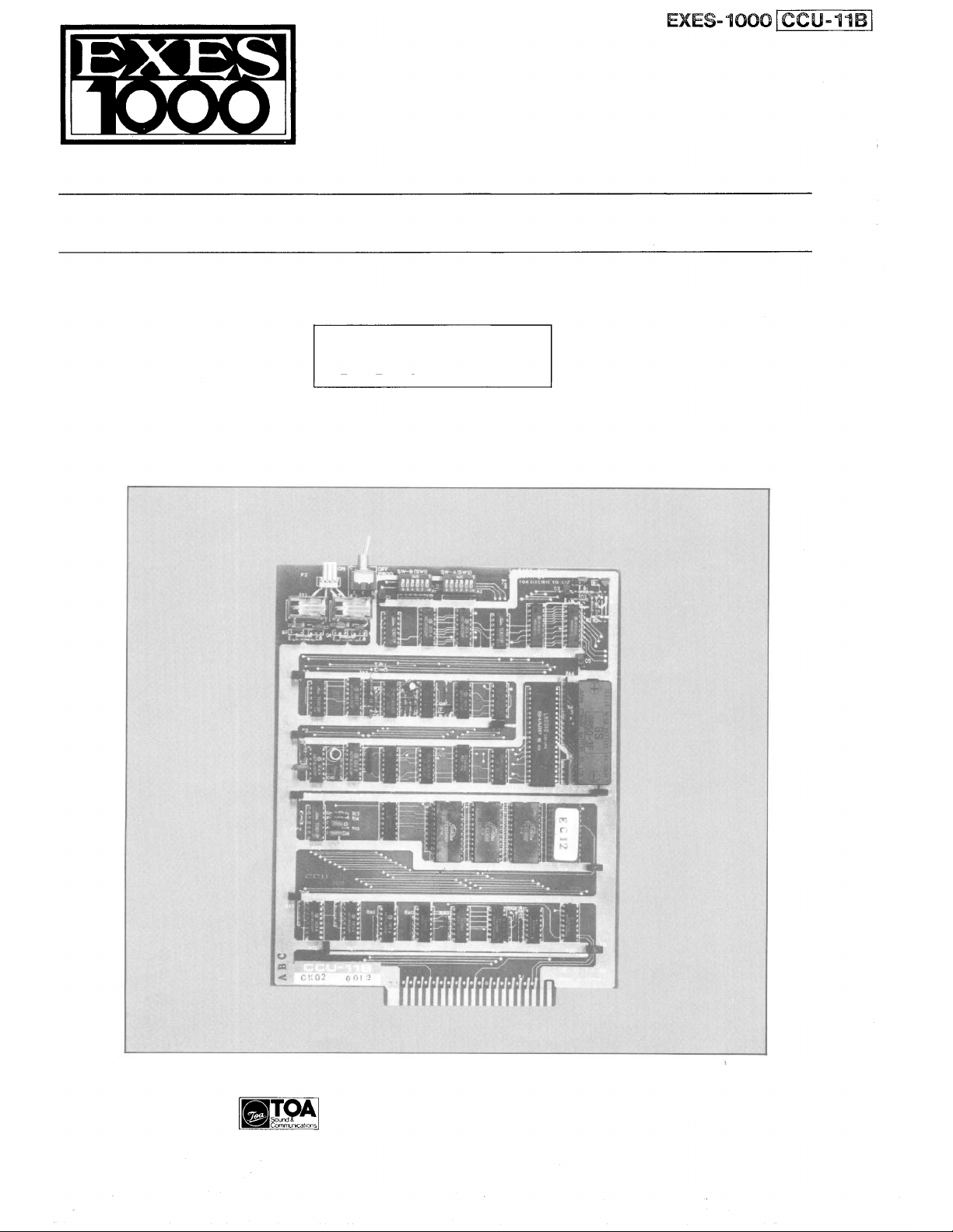
Central Control Unit
INTERCOM SYSTEM
CCU-11B
INSTALLATION HAND BOOK
TOA ELECTRIC CO., LTD.
KOBE, JAPAN
133-21-012-7A
Page 2

CONTENTS
1. Introduction ................................................................ 2
2.
Functions which
3.
Precautions
Require
for
Installation
Additional Units
of
CCU-11B
...........................................
........................................
Page
2
3
4.
Initial CCU-11B Set Up
5. DIP
6.
7.
Switch
Station
for
No. 11
Remote Control
Function
Programming
Relay
......................................................
Selection
(RY1 & RY2)
for
on
Each
CCU-11
Function
on
CCU-11B.
B.
....................................
................................
.................................
7-1 Functions and Operations ..............................................8
7-2 Connection ........................................................... .9
8.
Programming List
for
Functions
.................................................
.4
. . . . . 5
.8
10
.
5
— 1 —— —
Page 3
1. INTRODUCTION
This manual forms part of the Installation Manual for
TOA INTERCOM SYSTEM EXES-1000.
You may add to the CCU-11B to your TOA INTERCOM
SYSTEM EXES-1000, according to your specific needs,
to obtain various other functions.
Correct operation of these additional functions are not
available by only connection of the additional equip-
ments/devices.
Provision of such additional functions requires the
followings:
(1 ) Connection of the additional equipment, as required,
(2) Selection of functions which satisfy your needs and
setting up these functions in the respective equipment.
EXES-1000 Installation Hand Book
For (1 ) Connections of Equipment, etc., refer to Manual
of Installation Hand Book of EXES-1000 (EX-110)
Exchange.
This "Installation Hand Book of CCU-11B" deals prin-
cipally with (2) selection of functions and setting up of
respective equipment.
There are certain minimum installation requirements to
be met even though you may not need many additional
functions or additional equipment,
read "4. Initial CCU-11B Set Up (Page 4.)".
use only some of the additional functions or equipments,
it is not necessary to read instructions on unrequired
functions. Make sure, however, that careful study of the
necessary parts of this booklet should be done before
proceeding further.
it is still necessary to
When you may
EXES-1000 (EX-110)
Installation Handbook of Exchange.
or
EXES-1000 Installation Handbook
EXES-1000 (CCU-11B)
Installation Handbook
(133-21-012-7A)
2. FUNCTIONS WHICH REQUIRE ADDITIONAL UNITS
Functions of CCU-11B which require either the addition of specific units or processing in existing units are as men-
tioned below.
Function
Talk-Back from
paging speaker
Additional Equip-
ment Required
Talk-Back Unit
Unit Model No.
TKU-11
Remarks
Optional amplifier (10W max.) may be
required depending on application.
— 2 —
Page 4
3. PRECAUTIONS FOR INSTALLATION OF CCU-11B.
Please read following instructions carefully to ensure
proper operation of the CCU-11B.
1. Be careful about damage by static electricity as the
CCU-11B incorporates CMOS IC's. Do not touch com-
ponents and connectors.
2. Turn off the AC power switch when you take out or
insert the CCU-11B unit or any other unit.
3. Always insert the CCU-11B unit into the "CCU" slot.
Otherwise, there is a danger that the unit will be
damaged.
4. Make sure mini-jumper for battery back-up is always
placed in "ON" position each time it is used.
5. Incorrect setting of function select switches may lead
to incorrect performance.
6. Even if you do not need programming functions, be
sure to carry out initial programming and registration
at station No. 11 when you install the new unit.
Otherwise, some other functions may not work
properly.
7. The Ni-Cd battery GB50-3FA1 is capable of saving im-
portant memory registration data even at times of
power failure and we suggest you replace it at least
every 4 years.
8. When shipping the CCU-11B unit independently, place
the mini-jumper for battery back-up in "OFF"
position. Then cover CCU back with cardboard, wrap
connector section in aluminium foil and put it in a con-
ductive bag.
PROGRAM SWITCH for No. 11 Programming
Remote Control
Replay Output
(RY1
and
RY2)
Set this in "ON" position only at time of initial pro-
gramming of the exchange and registration of functions.
In this case, station No. 11 is "programming station" but
becomes a normal station when switch is placed in "OFF"
position.
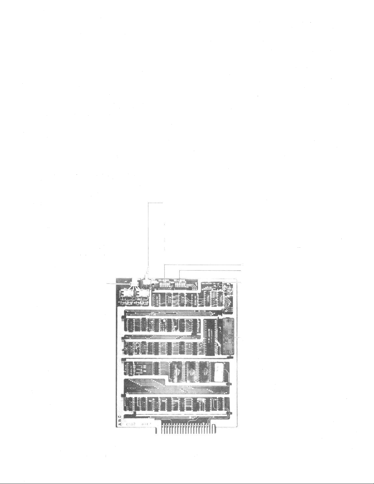
SW-B (1 ~ 6)/SW1 These switches
SW-A (1 ~ 6)/SW2 select functions.
Mini-Jumper for Battery Back-up.
Ni-Cd Battery
GB50-3FA1 (3.6V 50mAH)
— 3 —
Page 5

INITIAL CCU-11B SET UP
4
Make sure that you have turned off the AC power switch.
Set mini-jumper on the CCU card to "BATT. ON" position.
Set function selection DIP switches (SW-A & SW-B) on the CCU card for
required functions.
Insert the CCU card into the card rack of exchange, and make necessary
connection correctly.
Remove the CCU card from the card rack of exchange.
Turn on the AC power switch of exchange.
Turn on PROGRAM switch on the CCU card.
First installation?
No
Yes
Is all programming data required to be cleared?
Initial set
Dial operation from station #11
Confirmation tone
Touch ten times
No
Yes
Is Continuously Called Station necessary?
No
Is Secretary Transfer necessary?
No
Is Master/Sub-station necessary?
Is Executive Priority necessary?
Dial operation from station #11.
Touch
Turn off PROGRAM switch on the CCU card of exchange.
Station #11 returns to an ordinary station.
Key.
Yes
To Continuous Calling Tone
Yes
To Secretary Transfer
Yes
To Master/Sub-station
Yes
To Executive Priority
— 4 —
Page 6

5 DIP SWITCH FOR FUNCTION SELECTION ON CCU-11B
The DIP switches on the CCU-11B allow selection of the following functions;
A. All Call Paging and Response
B. Call Holding/Call Transfer
C. Calling Tone Duration
D. Time Interval Adjustment before All Call Paging
1: BATT. OFF
2: BATT. ON
Switches
Mini-Jumper for Battery
OFF
OFF
Functions
Remote Control (Door)
SW-A (SW2)
Continues Calling Tone
E. PTT Control
F. Priority and Executive Priority
G. Remote Control
H. Continuous Calling Tone
DIP-SW "ON "Position DIP-SW "OFF "Position
Battery "ON"
Position
Make/Break Relay Output
Activate
One shot Relay Output
(4
sec.)
Battery "OFF"
Position
Not Activate
SW-B (SW1)
OFF
ON
PROG
sw
OFF
OFF
Priority & Executive Priority
Press to T alk Control
Time Interval Adjustment
before All Call Paging Preannounce Tone
Calling Tone Duration
Call Transfer
All Call Paging & Response
Programming Switch
Activate
Activate
1 ~ 2
sec.
Short (0.7 sec)
Activate
Activate
Station No. 11 is
"Programming station'
Not Activate
Not Activate
None
Long (1.3 sec)
Not Activate
Not Activate
Station No. 11 is a
normal station
— 5 —
Page 7

6. STATION NO. 11 PROGRAMMING FOR EACH FUNCTION
Use station #11 for programming of "Continuous Calling Tone", "Secretary Transfer", "Master/Sub-Relationship" and/or
"Executive Priority" functions.
Remarks: 1. In the event of failure to touch keys for correct dialing, privacy tone will be sound.
Re-start from the beginning.
2. When All Call Paging is used, the registration to the station #10 can not be done.
The following shows how to register the functions:
1. Continuous Calling Tone
New registration ?
Yes
Ascertain holding tone.
Continuously called station number
No
All registration finished ?
Yes
Release ?
Yes
Ascertain holding tone.
Station number to be released
No
Release finished ?
Yes
Return
No
No
— 6 —
Page 8

2. Secretary Transfer
New registration ?
Ascertain holding tone
Station Number Station Number
of executive of secretary
All registration finished ?
Release ?
Station Number Station Number
of executive of executive
Ascertain holding tone
Release finished ?
Return
3. Master/Sub-Relationship
New registration ?
Sub-station Number Master station Number
All registration finished ?
Ascertain holding tone
Release ?
Ascertain holding tone
Sub-station Number Sub-station Number
Release finished ?
Return
4. Executive Priority
New registration ?
Ascertain holding tone
Number of station where Executive Priority is
registered.
All registration finished ?
Release ?
Ascertain holding tone
Number of station where registration of Executive
Priority is release.
Release finished ?
Return
— 7 —
Page 9

7. REMOTE CONTROL RELAYS (RY1 & RY2) ON CCU-11B
Remark: Relay Control Capacity: 30VDC, 2A
Relays (RY1 & RY2) on CCU-11B are available for following functions.
Relay
No.
RY1
RY2
DIP Switch Position
SW-A-3 "OFF"
SW-A-3 "ON"
SW-B-2 "OFF"
Functions and Operations
A Door Remote Control (One-shot-Make Relay Output)
Every master station can be used as a remote control device for door open-
ing. Touch dial
gives approximately 4 seconds make-contact for
the door opening.
B Door Remote Control (Make-Break Relay Output)
Every master station can be used as a remote co ntrol device for door
opening. Touch dial
opening. Then touch dial
gives continuous make-contact for door
gives break-contact for door closing.
C Power ON/OFF Remote Control
When the system is used in conjunction with PA amplifier for the external
All-Call paging, the power switch of the PA amplifier can be turned on/off
with the relay built in the system. Touch dial
gives the make-contact
together with the All-Call function until the function is canceled by dialing
(Remark: Touch dial
gives break-contact of the relay.)
SW-B-2 "ON"
D Press To Talk Control
Touch dialing the specific station #17.
One way conversation is activated while the Press-To-Talk bar is continu-
ously depressed, same as the Press-To-Talk (selected simplex ) function, and
the relay is activated with continuous make-contact.
One way conversation is reversed when the Press-To-Talk bar is released, and
the relay is activated with break-contact.
— 8 —
Page 10

7-2. Connections
A. Connect 4-pin connector from TBM-11 (Terminal module) to P2 connection socket on the CCU-11B.
B. R M1 terminals on TBM-11 are for the door remote control relay contacts and RM2 terminals on TBM-11
are for the power ON/OFF remote control or press to talk remote control relay contacts.
(Please refer to the following diagram.)
DOOR
YEL
RM
ORG
1
RED
RM
BRN
2
AC
AC
In the case of power ON/OFF remote control.
— 9 —
Page 11

8. PROGRAMMING LIST FOR FUNCTIONS
Use these tables to keep a record of those functions assigned to each station.
Function Table for Stations
Functions
Name
10
11
12
13
14
15
16
17
18
19
20
21
22
23
24
25
26
27
28
29
30
31
32
33
34
35
36
37
38
39
40
41
Tone
Calling
Continuous
Priority
Executive
No.
Station
Secretary
No.
Master
Station
— 10 —
Page 12

TOA ELECTRIC CO., LTD.
KOBE, JAPAN
Printed in Japan
 Loading...