

Page 1
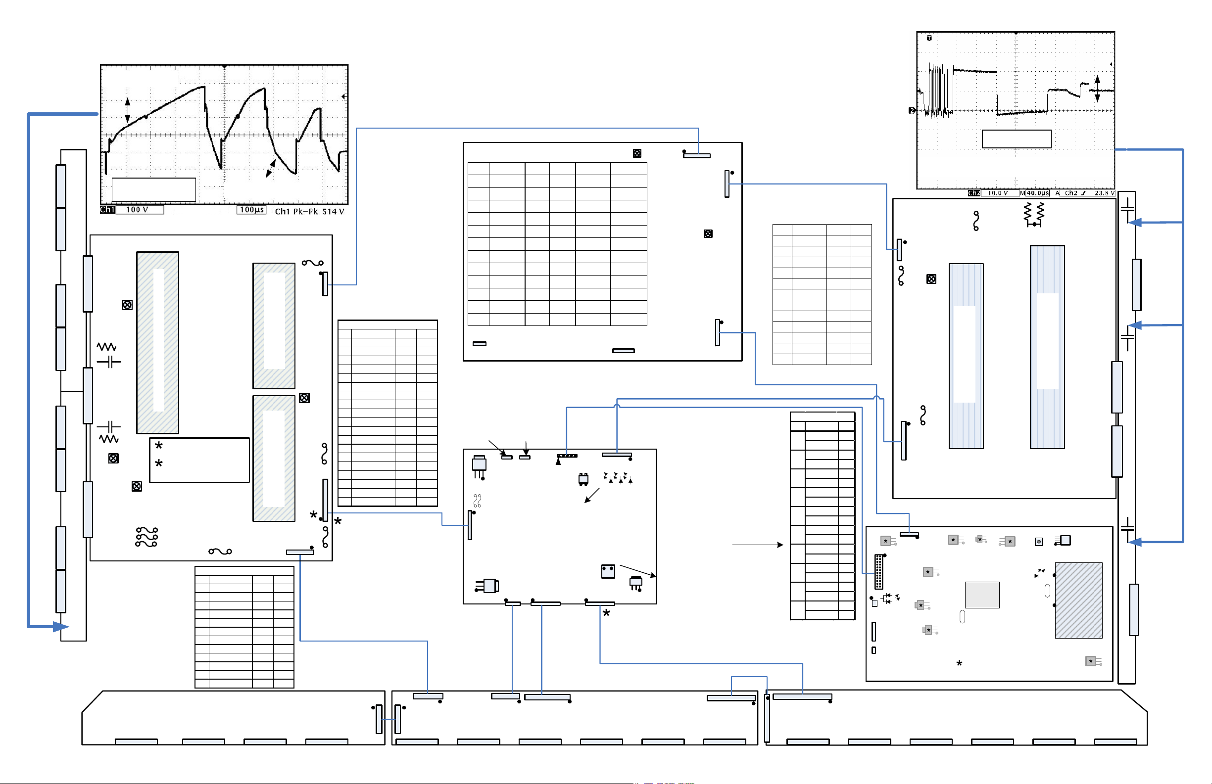
Z-SUS DRIVE WAVEFORM
Y-SUS TP
P110
P120
P130
P140
P210
P220
P230
P240
Y-SUS TopY-SUS Bottom
P206
P100P200
FG5V
-VY TP
SCAN
P207
SCAN
VSC TP
FG5V
P208
125V 1.5A
125V 1.5A
125V 1.5A
Y-SUS DRIVE WAVEFORM
(RAMP) SUS-UP
150Vp/p
72V~83V (AC) rms
(Dark to White)
(RAMP) SUS-DOWN
100uS
Use RMS just for a check to see if Y-SUS is running.
Not for Adjustments
Discrete Components (Non-IPMs)
(Non-IPMs)
Set-dn
Y-SUS
R201
R202
VSC measurement is
(Non-IPMs)
across R202
VSC
-VY measurement is
across R201
-VY
All -90V
FS502
FS501
FS504
FS503 (5V)
125V 5A
P210 / P242
Pin Label STBY Run
1 Va_C 0V 65V
2 Va_C 0V 65V
3 VPP_Out_XR 0V 62.4V
4 VPP_Out_XR 0V 62.4V
5 VPP_Out_XL 0V 62.3V
6 VPP_Out_XL 0V 62.3V
7 VPP_Out 0V 63.3V
8 VPP_Out 0V 63.3V
9GndGndGnd
10 Gnd Gnd Gnd
11 +15V 0V 15.9V
12 +15V 0V 15.9V
LEFT X DRIVE
FS201 Vs
250V 4A
Discrete Components
P209
Set-up
Discrete Components
FS202
5V
10A
125V
P102
P210
Vs, Va and M5V
Pin Label STBY Run
10 SET_UP 0V 0.26V
11 SET_DN 0V 0.2V
12 PASS_TOP 0V 0.2V
13 DELTA_VY 0V 0.16V
14 DET_LEVEL 0V 0V
15 SLOPE_KEY 0V 0V
16 SET_UP 0V 1.9V
17 SET_DN 0V 1.4V
18 X_ER 0V 2.9V
19 Y_ENABLE 0V 0.6V
P102 / P111
1 CLK 0V 3.2V
2 STB 0V 0.76V
3OSC10V0V
4OSC20V3V
5DATA0V0.6V
6SUS_DN0V0V
7SUS_UP0V2V
8 ER_DN 0V 1.2V
9 ER_UP 0V 2V
Test points are open
lands at P102 with pin
one at the bottom
FS701
Va
125V 10A
5V for Control PWB
Delivered through P102
15V for Z-SUS also
routed through P102 and
out P163
Va and 16V
P121
50PG20 INTERCONNECT DIAGRAM
During SMPS Test (Described below), P803 disconnected;
1) P801 and P802 connected. Y-SUS and Z-SUS will produce sustain waveforms.
2) P801 connected P802 disconnected, Y-SUS will produce sustain waveform, Z-SUS does not.
3) P801 disconnected P802 connected. No SUS waveforms are produced due to a loss of control PWB B+
routed through the Y-SUS PWB.
D16
D17
IC171
VS Adj
P801
P802
VA Adj
SMPS
POWER
SUPPLY
P803
Remove all input signals
from the unit so the
menu will be the only
video to be found on the
LVDS cable.
NOTE: White noise from
the tuner may cause
these signals to vary.
These were taken with
the unit set to
component with no input
signal.
See next page for
waveforms
Short across the two points
labeled Auto Gen to generate
a test pattern.
Va and 16V
P211
Vs, Va and M5V
P2 / P163
Pin Label STBY Run
1 SUS-DN 0V 16V
2 SUS-UP 0V 16V
3 ER-DN Gnd Gnd
4 ZBIAS 0V 0.48V
5 ZB-CON 0V 0.27V
6 ER-UP 0V 0.1V
7 ENABLE 0V 0.06V
8 none Gnd Gnd
9 none 0V 0V
10 none 0V 1.93V
11 none 0V 2.66V
12 none Gnd Gnd
Pin State Ref#
Menu Off 10
11
Menu On 11
Menu Off 08
12
Menu On 09
Menu Off 12
13
Menu On 13
Menu Off 06
14
Menu On 07
Menu Off 14
15
Menu On 15
Menu Off 04
16
Menu On 05
Menu Off 16
19
Menu On 17
Menu Off 02
20
Menu On 03
Menu Off 18
21
Menu On 19
Menu Off 00
22
Menu On 01
To keys and IR
(3.3V)
10,11,12
P331
P311
P233
P201 P202 P203 P204 P205 P206 P301 P302 P303 P304 P305 P306P101 P102 P103 P104
P242
P803 Connector "SMPS" to P701 "Main"
Pin Label STBY Run No Load Diode
1, 2 15V 0V 16V 16V 2.26V
3, 4 Gnd Gnd Gnd Gnd Gnd
5, 6 12V 0V 12V 12V 2V
7, 8 Gnd Gnd Gnd Gnd Gnd
9-12 5V 5V 5V 5V 1.7V
13-16 Gnd Gnd Gnd Gnd Gnd
17 5_V Det 0V 5V 5V 1.56V
18 AC Det 5V 5V 5V 2.56V
19 RL_On 0V 4.5V 0V 2.6V
20 Vs_On 0V 3.2V 0V 2.7V
21 M5V_ON 0V 3.2V 0V 2.6V
22 AUTO 0V 0V 5V 2.1V
A/C IN
No Connection
P701
SMPS Test – Unplug P803 If all supplies do not run when A/C is
reapplied, disconnect P801 and P802 one at a time to isolate the
excessive load. This supply will operate with no external load.
Software
Download
P121
P164 P131
Pin 1 (5V)
Pin 2 (3.3V)
Pin 3 (0V)
5V Fuses
1
Crystal
With the unit on. If none of
D15, 16, 17 are illuminated.
Check supplies to the PCB.
If they are present replace
the Control PCB
PCB
(3.3V)
(3.3V)
48,49,50
(3.3V)
48,49,50
10,11,12
P151 P161 P162
P241
P232
15V
P163
D15
Auto Gen
If the complaint is no video and shorting
the points (AutoGen) causes video to
appear suspect the Digital PCB.
M5V
15V
(3.3V) to
P161, P162
No
Connection
IC121
FL111 FL112
P111
CONTROL
IC151
Pin 1 (5V)
Pin 2 (3.3V)
Pin 3 (0V)
CENTER X DRIVE
P302
To Speakers
P3
FS2 (5V)
125V 10A
FS3 (16V)
125V 1.5A
P2
15V
** LD703 Lights Red in Stby. 5VSBY from SMPS OK.
P701
IC705
P302
**LD703
Q706
IC708
P303
CN701
MAIN PCB
VZ Bias
52V (AC) rms
Use RMS just for a check to see if Z-SUS is running.
Not for Adjustments
FS1 (Vs)
250V 4A
VZB TP
VZB
Discrete Components
Discrete Components
(Non-IPMs)
(Non-IPMs)
Z-SUS
Set on, Lights Red 5V General OK. Appears Amber
IC702
Reset
IC709
IC701
LD400 lit during initialization.
Tuner lock OK turns LED off.
IC706
IC100
Micro
X100
LD400
12 Meg
X400
25 Meg
Run Only
1.5V SBY
IC501
Grayed Out ICs are
located on Back
IC902
Pin 16
TUNER
Pin 1
IC805
RIGHT X DRIVE
P4
P5
Z-SUS TP
Z-SUB
Z-SUS TP
P6
Z-SUS TP
P10
P11
Z-SUS TP
IC701
1) 5V
2) 0V
P8
3) 5V
IC702
3) 5V
2) 3.3V
1) 0V
IC705
1) 5V
2) 3.29V
3) 0V
IC706
1) 5V
2) 3.64V
3) 1.38V
IC709
1) 3.29V
2) 1.26V
3) 0V
IC501
1) 3.3V
2) 1.8V
3) 0V
IC805
1) 5V
2) 3.3V
3) 0V
IC902
5) .29V
4) 5V
3) 0V
2) 0V
1) 0V
IC708
1) 5V
2) 3.3V
3) 0V
Page 2
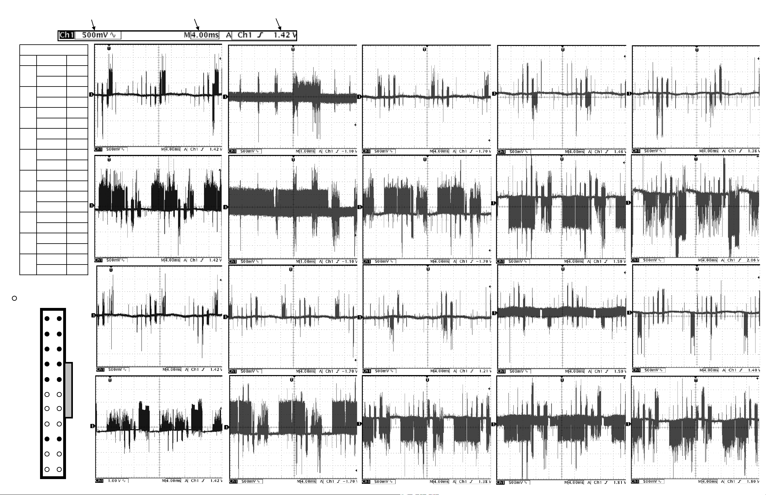
Volts per division
Time per division Trigger offset
11
11
12
12
13
13
14
14
15
15
16
16
19
19
20
20
21
21
22
22
P302
P302
00
Ref #StatePin
Ref #StatePin
10Menu Off
10Menu Off
11Menu On
11Menu On
08Menu Off
08Menu Off
09Menu On
09Menu On
12Menu Off
12Menu Off
13Menu On
13Menu On
06Menu Off
06Menu Off
07Menu On
07Menu On
14Menu Off
14Menu Off
15Menu On
15Menu On
04Menu Off
04Menu Off
05Menu On
05Menu On
16Menu Off
16Menu Off
17Menu On
17Menu On
02Menu Off
02Menu Off
03Menu On
03Menu On
18Menu Off
18Menu Off
19Menu On
19Menu On
00Menu Off
00Menu Off
01Menu On
01Menu On
01
02
Pin 22 - Menu off
Pin 22 - Menu on
Pin 20 - Menu off
04
05
06
Pin 16 - Menu of f
Pin 16 - Menu on
Pin 14 - Menu of f
08
09
10
Pin 12 - Menu off
Pin 12 - Menu on
Pin 11 - Menu off
12
13
14
Pin 13 - Menu of f
Pin 13 - Menu on
Pin 15 - Menu of f
16
17
18
Pin 19 - Menu off
Pin 19 - Menu on
Pin 21 - Menu off
Connector P302 Configuration
- indicates signal pins.
2
4
6
8
10
12
14
16
18
20
22
1
3
5
7
9
11
13
15
17
19
21
03
Pin 20 - Menu on
07
Pin 14 - Menu on
11
Pin 11 - Menu on
15
Pin 15 - Menu on
19
Pin 21 - Menu on
 Loading...