

Page 1
VIVOTEK - A Leading Provider of Multimedia Communication Solutions
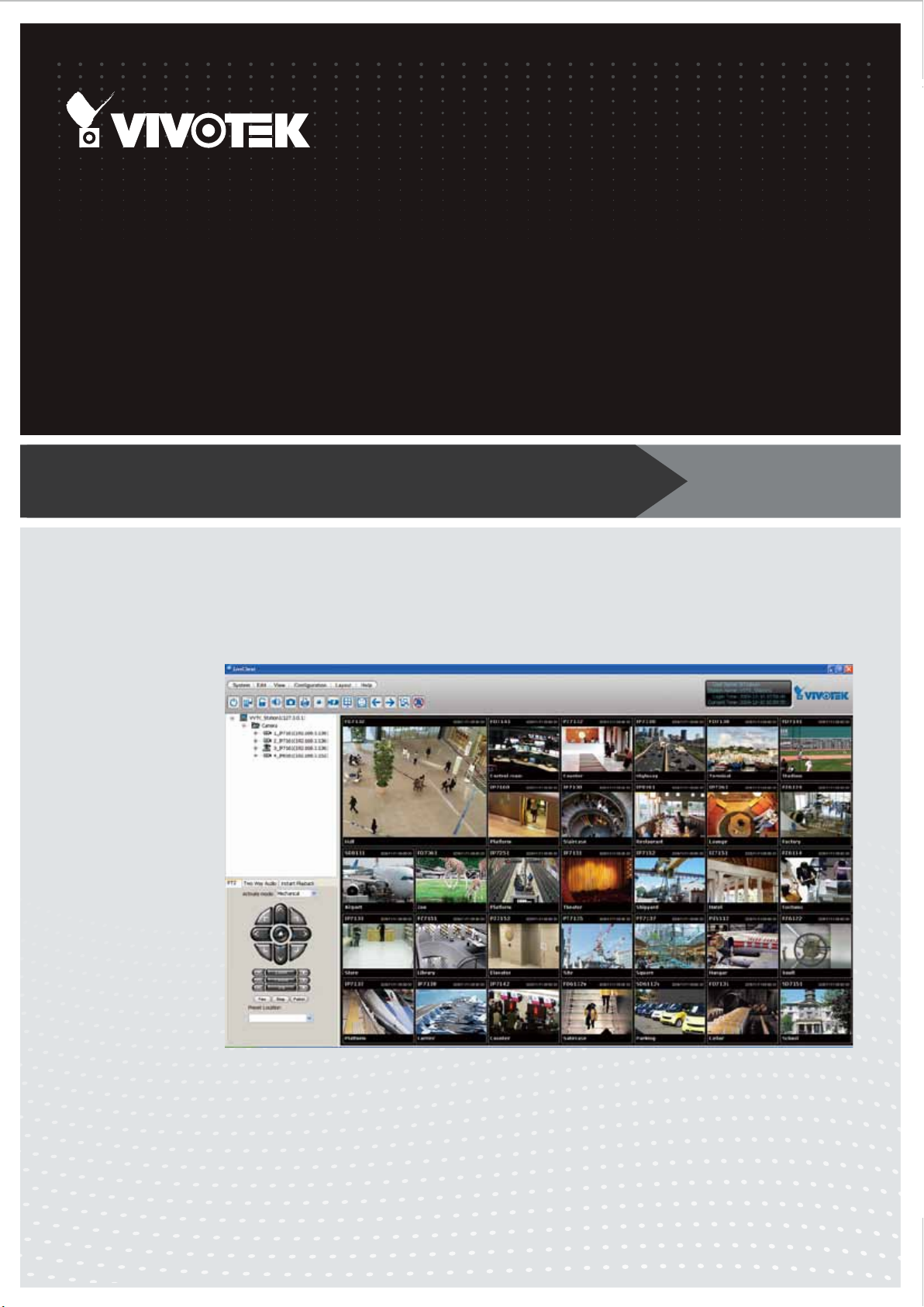
Free-standard
ST7501
Recording software
User’s Manual
32-channel video recording • Records data on to hard
disks or networked storage • Local or remote LiveClient
Rev. 1.7.7a
User's Manual - 1
Page 2

VIVOTEK - A Leading Provider of Multimedia Communication Solutions
Table of Contents
Revision History ..................................................................................................................................................... 8
Getting Started ............................................................................................................................................................ 9
Introduction ............................................................................................................................................................. 9
Special Features ............................................................................................................................................. 9
Server and Client Components ............................................................................................................................ 10
Usage Scenario .................................................................................................................................................... 10
Technical Specications ....................................................................................................................................... 11
Server Functionality .............................................................................................................................................. 12
LiveClient Functionality ........................................................................................................................................ 13
Playback Functionality .......................................................................................................................................... 14
Minimum System Requirements .......................................................................................................................... 15
Software Installation .................................................................................................................................................. 17
Installing the Software .......................................................................................................................................... 17
ST7501 Server .......................................................................................................................................................... 20
Activating the Server ............................................................................................................................................ 20
How to Congure the Server ................................................................................................................................ 20
How to Stop/Reboot the Server ............................................................................................................................ 20
LiveClient Conguration ............................................................................................................................................ 21
Activating the LiveClient and Logging in to a Server ............................................................................................ 21
LiveClient User Interface ...................................................................................................................................... 22
Menu Bar ....................................................................................................................................................... 22
Status Panel .................................................................................................................................................. 22
Help Panel ............................................................................................................................................................ 23
Quick Access Bar .......................................................................................................................................... 24
Live Video Monitoring Window ...................................................................................................................... 24
Hierarchical Management Tree ..................................................................................................................... 25
Camera Control Panel ................................................................................................................................... 26
Pan/Tilt/Zoom (PTZ) Control Panel ........................................................................................................ 26
Two Way Audio Control Panel ................................................................................................................ 28
Language Selection ............................................................................................................................... 28
Event Window ............................................................................................................................................... 29
Instant Playback ............................................................................................................................................ 30
Instant Replay ............................................................................................................................................... 31
Audio Control ................................................................................................................................................ 32
How to Manage Devices ...................................................................................................................................... 33
Insert Cameras .............................................................................................................................................. 33
Enable SVC .................................................................................................................................................. 37
Insert a Video Server ..................................................................................................................................... 40
Update Devices ............................................................................................................................................. 42
Delete Devices from the Server .................................................................................................................... 43
2 - User's Manual
Page 3

VIVOTEK - A Leading Provider of Multimedia Communication Solutions
Batch Insert Devices ..................................................................................................................................... 44
Camera Conguration ................................................................................................................................... 48
View Live Videos ........................................................................................................................................... 51
Dual / Multiple Streams .......................................................................................................................... 51
Fisheye Display Modes .......................................................................................................................... 51
Refresh ................................................................................................................................................... 56
Streaming Server ................................................................................................................................... 56
Get Public IP .......................................................................................................................................... 56
Camera Settings .................................................................................................................................... 57
Remove Live Video from the Video Monitoring Window ............................................................................... 57
How to Change the LiveClient Layout .................................................................................................................. 58
Changing the Layout of the Live Video Monitoring Window .......................................................................... 58
Switch Video Channels .......................................................................................................................... 58
Congure Layout Mode .......................................................................................................................... 59
Rotating Video Pages ............................................................................................................................ 60
Edit Layout ............................................................................................................................................. 60
Maximize/Minimize the Live Video Monitoring Window ................................................................................. 62
View Live Video on Dual Monitors ................................................................................................................. 63
View up to 32 channels simultaneously ................................................................................................. 64
Using different layouts on each monitor ................................................................................................. 64
View Live Video with Multiple Monitors ......................................................................................................... 65
How to Manage User Accounts ............................................................................................................................ 66
The Default User Roles and Permissions of User Accounts ......................................................................... 66
Manage a User Account ................................................................................................................................ 68
Add a New User Account ....................................................................................................................... 68
Permission of the User Account .................................................................................................................... 69
Delete the User Account ............................................................................................................................... 70
How to Set up Association Management .............................................................................................................. 71
Association Management .............................................................................................................................. 71
How to Set up Event Management ....................................................................................................................... 73
Event Management ....................................................................................................................................... 73
How to Congure the Station General Settings .................................................................................................... 80
Server Settings .............................................................................................................................................. 80
Log Settings .................................................................................................................................................. 80
How to Congure Station Network Settings ......................................................................................................... 81
Port Settings .................................................................................................................................................. 81
UPnP Settings ............................................................................................................................................... 81
Proxy Settings ............................................................................................................................................... 81
How to Edit Recording Groups ............................................................................................................................. 82
Recording Storage Settings .......................................................................................................................... 82
Default Storage Group Settings ............................................................................................................. 83
Add New Recording Group(s) ................................................................................................................ 85
How to Edit Recording Schedules ........................................................................................................................ 86
Edit Schedule List ......................................................................................................................................... 87
Add Schedules ....................................................................................................................................... 87
Rename Schedules ................................................................................................................................ 87
User's Manual - 3
Page 4

VIVOTEK - A Leading Provider of Multimedia Communication Solutions
Delete Schedules ...................................................................................................................................87
Load/Save Schedule Templates .............................................................................................................88
Edit Camera List ............................................................................................................................................89
Edit Time Frame List .....................................................................................................................................90
Add New Time Frames ...........................................................................................................................91
Recording Settings .................................................................................................................................92
The Concept of Repeat Frequency ...............................................................................................................93
Repeat Frequency: Daily Setting ...........................................................................................................94
Repeat Frequency: Weekly Setting (Day-based) ...................................................................................97
Repeat Frequency: Monthly Setting (Day-based) ................................................................................100
Repeat Frequency: Yearly Setting (Day-based) ...................................................................................102
How to Manually Begin /Stop Recording ............................................................................................................104
How to Edit Scheduled Backup Settings ............................................................................................................105
Select Backup Source .................................................................................................................................105
Setup Backup Schedule ..............................................................................................................................106
Select Backup Target ..................................................................................................................................106
Other Options ..............................................................................................................................................106
How to Congure Station Server Settings ..........................................................................................................107
DDNS Settings ............................................................................................................................................107
Network Storage Server Settings ................................................................................................................108
SMTP Settings ............................................................................................................................................109
Relay Settings ............................................................................................................................................. 110
How to Use the Talk Panel ................................................................................................................................. 111
Add a Camera to the Talk Panel ..................................................................................................................111
Remove a Camera from the Talk Panel ......................................................................................................113
How to Congure E-map Settings ...................................................................................................................... 114
Upload an E-map ........................................................................................................................................114
User Interface of E-map Settings Page (View Mode) ..................................................................................115
Quick Access Bar ................................................................................................................................. 116
Status Panel ......................................................................................................................................... 116
User Interface of E-map Settings Page (Edit Mode) ................................................................................... 117
Device Management ...................................................................................................................................118
Live View Dialog Settings ............................................................................................................................ 119
Open Live View Dialog ......................................................................................................................... 119
Send to Single View ............................................................................................................................. 119
E-map Link ..................................................................................................................................................120
How to Congure Client Settings .......................................................................................................................123
Snapshot Settings .......................................................................................................................................123
Take a Snapshot ..................................................................................................................................124
Recording Settings ......................................................................................................................................125
Type 1: Record to EXE ........................................................................................................................125
Type 2: Record to 3GP .........................................................................................................................125
Type 3: Record to AVI ..........................................................................................................................126
Built-in Media Player--EXE ...................................................................................................................129
View Settings ...............................................................................................................................................131
Display Location ...................................................................................................................................131
Date and Time Format .........................................................................................................................132
4 - User's Manual
Page 5

VIVOTEK - A Leading Provider of Multimedia Communication Solutions
Video Display Mode .............................................................................................................................132
Font Settings ........................................................................................................................................132
General Settings .........................................................................................................................................133
System Settings ...................................................................................................................................133
Event Settings ......................................................................................................................................134
Rotation Settings ..................................................................................................................................134
Display Settings ...................................................................................................................................135
Joystick Settings .........................................................................................................................................136
Enable Joystick ....................................................................................................................................136
Proxy Settings .............................................................................................................................................140
How to Search for a Device on the Hierarchical Management Tree ..................................................................141
How to Print a Video Image ................................................................................................................................142
How to Lock LiveClient for Security Concerns ...................................................................................................142
How to Log out from the Server .........................................................................................................................143
How to Exit LiveClient ........................................................................................................................................143
Playback Conguration............................................................................................................................................144
Activating Playback and Logging in to a Server .................................................................................................144
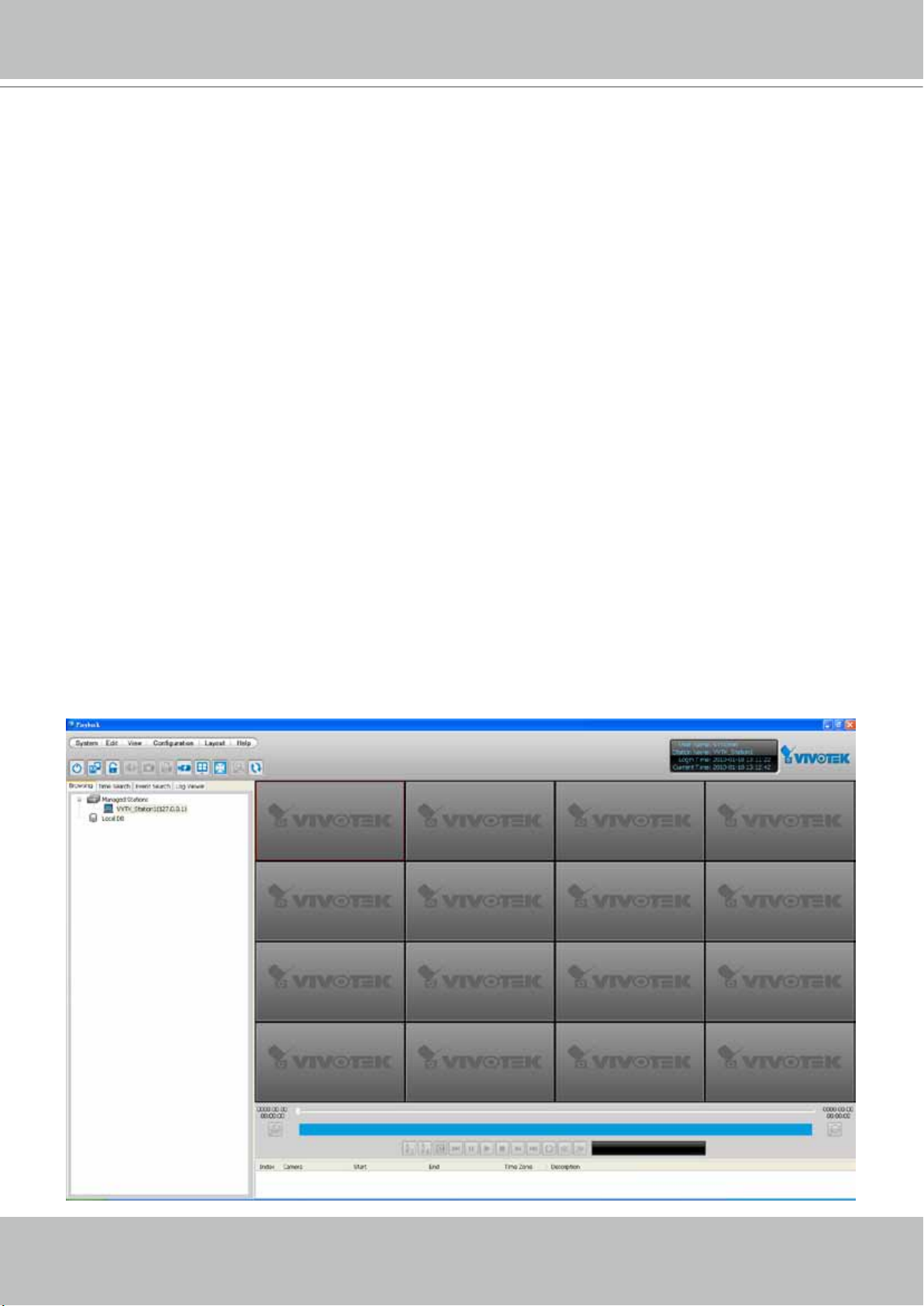
Playback User Interface .....................................................................................................................................145
Menu Bar .....................................................................................................................................................145
Status Panel ................................................................................................................................................145
Quick Access Bar ........................................................................................................................................146
Recorded Video Playback Window .............................................................................................................146
Language Selection ....................................................................................................................................147
Query Panel-- Browsing Page .....................................................................................................................147
Query Panel--Time Search Page ................................................................................................................149
Query Panel--Event Search Page ...............................................................................................................150
Query Panel--Bookmark Search Page ........................................................................................................151
Query Panel--Log Viewer Page ...................................................................................................................152
Video Clips List Window ..............................................................................................................................153
Playback Control Panel ...............................................................................................................................154
How to Playback Recorded Video ......................................................................................................................155
Select a Recorded Video Clip .....................................................................................................................155
Remove Recorded Video Clips from Video Cells ........................................................................................157
Timeline Slider Bar and Histogram ..............................................................................................................157
Zoom in / out of the Histogram ....................................................................................................................158
Audio Control ..............................................................................................................................................159
How to Change the Playback Layout .................................................................................................................160
Changing the Layout of the Recorded Video Playback Window .................................................................160
Switch Video Channels ........................................................................................................................160
Congure Layout Mode ........................................................................................................................160
Maximize/Minimize the Recorded Video Playback Window ........................................................................161
View Recorded Video with Multiple Monitors ..............................................................................................162
How to Backup Recorded Video ........................................................................................................................163
How to Search for a Video Clip in a Specic Period of time ...............................................................................169
How to Add a Bookmark .....................................................................................................................................170
How to Search for Events ...................................................................................................................................171
User's Manual - 5
Page 6

VIVOTEK - A Leading Provider of Multimedia Communication Solutions
Select Event Category ................................................................................................................................172
Event Category- All Events ..................................................................................................................172
Event Category- All Motion Events.......................................................................................................172
Event Category- All IVA events ............................................................................................................173
Event Category- All DI Events ..............................................................................................................173
Event Category- Named DI Events ......................................................................................................174
Start Event Search ......................................................................................................................................175
Backup the Event Videos ............................................................................................................................176
How to Search for a Bookmark ..........................................................................................................................177
How to Search Logs ...........................................................................................................................................178
Select Log Category/Log Type/Log Level ...................................................................................................179
Search All Local Logs...........................................................................................................................180
Search Login History ............................................................................................................................180
Search Login Activities ......................................................................................................................... 181
How to Congure Client Settings .......................................................................................................................183
Snapshot Settings .......................................................................................................................................183
Export Settings ............................................................................................................................................183
View Settings ...............................................................................................................................................185
Proxy Settings .............................................................................................................................................185
General Settings .........................................................................................................................................185
System Settings ...................................................................................................................................185
Display Settings ...................................................................................................................................185
How to Congure Video Enhancement ..............................................................................................................185
How to Search for a Device on the Hierarchical Management Tree ..................................................................185
How to Print a Video Image ................................................................................................................................185
How to Lock Playback for Security Concerns ....................................................................................................186
How to Log out from the Server .........................................................................................................................186
How to Exit Playback ..........................................................................................................................................186
Import and Export Utility ..........................................................................................................................................187
Export Utility .......................................................................................................................................................187
Import Utility .......................................................................................................................................................187
Service Control Tool ................................................................................................................................................188
6 - User's Manual
Page 7

VIVOTEK - A Leading Provider of Multimedia Communication Solutions
Revision History
Rev. 1.5.2:
* Automatically saves the last layout when the management session is closed (for both
LiveClient and Playback).
* Added Playback as one of user's previlege options.
* A web session with an individual camera can be launched by a double-click on a camera's
icon.
Rev. 1.6.1:
* Added description for Adaptive Frame Rate Adjustment with the new SVC codec cameras.
* Added description for Auto Stream Size functionality.
* Added functionalities related to FE8171V fisheye camera.
* Added description for fisheye-specific screen control and playback functions.
* Replaced some description for the changes/improvements made on the user interface.
* Modified the graphic size limitation of E-map upload from 5MB to 2MB.
Rev. 1.6.18:
* Corrected editorial errors and added a conceptual drawing for the SVC-T (Temporal) func-
tion.
Rev. 1.6.1.11:
* Changed the maximum number of channel number in trial mode to 256.
Rev. 1.7.7:
* Added description for the Bookmark function.
* Added description for the Instant Replay function.
* Reflected changes on the new display and layout design.
* Added Hot key combinations.
* Removed the 1P3R fisheye display mode, which was removed from specifications later.
Rev. 1.7.7a:
* Removed description for the PiP function, which is not supported on ST7501.
* Removed description for the Synchronous and Asynchronous playback, which is not sup-
ported on ST7501.
* Removed description for the Web Access function, which is not supported on ST7501.
User's Manual - 7
Page 8

VIVOTEK - A Leading Provider of Multimedia Communication Solutions
Getting Started
Introduction
VIVOTEK ST7501 is the new generation recording software, featuring reliable recording and
easy system management for diverse IP surveillance applications. ST7501 has three major
components including: ST7501 Server for recording, ST7501 LiveClient for viewing live media
data and system management, and ST7501 Playback for browsing the database and retrieving
the recorded media data. You can install and run the three components on a single computer, or
install them on three separate computers.
ST7501 Server is able to record network video streams up to 32 channels, and ST7501 LiveClient allows for real-time remote monitoring. For video playback, you can use ST7501 Playback
to retrieve the database with multiple advanced functions such as searching, browsing, and exporting. With ST7501 LiveClient and ST7501 Playback installed on other computers in different
locations, you can have live viewing and database access for more efficient video management.
Working seamlessly with VIVOTEK network cameras and video servers, ST7501 recording software provides you with a reliable and seamless video surveillance system.
Special Features
Convenient Remote Access via Client/Server Architecture
Convenient Remote Access via Client/Server Architecture
Effective & Reliable Event Trigger Management
Real-time 32-channel Live Viewing and 16-channel Playback
Multiple Simultaneous Streams for Different Media Platforms
Activity Adaptive Streaming for Dramatically Reducing Bandwidth and Storage Space
Extremely Versatile Settings for Recording Storage and Recording Schedule Management
Role-based User Management to Enhance Security Operations
Efficient Data Backup, Search, and Export
Intelligent PTZ/ E-PTZ Remote Camera Control
Overall Device Management through Intuitive E-map Feature
Instantly Playback Event Recording
Built-in Instant Player for Playback
Accessible through NAT Using the Public IP
Supports Two Way Audio
Supports Auto Stream Size
Supports SVC adaptive frame rate setting
Bookmark function to mark a specific point in time during playback with event description.
* The number of linked devices will depend on the license on the key dongle.
* The ability to extend devices is also subject to the network bandwidth and computer performance.
8 - User's Manual
Page 9
VIVOTEK - A Leading Provider of Multimedia Communication Solutions
Server and Client Components
There are two components in ST7501: LiveClient and Playback.
The Server provides a centralized management site for video recording. LiveClient is a client
program for the user to login and modify the server's conguration, edit the server's recording
storage, schedules and many other functions on the server; Playback is another client program
for the user to login and browse the recorded video database and video clips related to specic
events on the server.
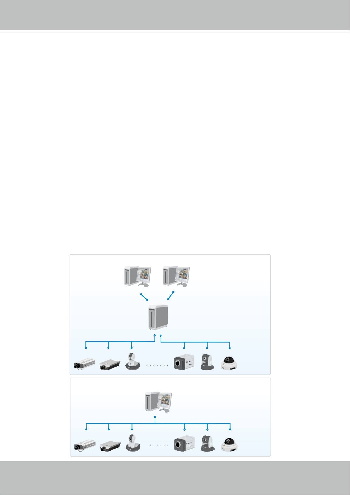
Usage Scenario
The three components can be installed separately or combined together on the same host. You
can just install the components you need on your local host. For example, you can only install
ST7501 LiveClient on your local computer to monitor the live video from a remote ST7501
Server; or you can only install ST7501 Playback on another local computer to login to a remote
server to review recorded videos.
For users that only manage a few cameras, we recommend installing the client and server
components on the same computer. A host with all of the three components installed is recognized
as a stand-alone site. All the functions can be simultaneously performed on one single site.
Shown below is the usage scenario of ST7501 Server and client components.
Remote Server Structure
ST7501 LiveClient
Router
ST7501 Server
Network Cameras
ST7501 Playback
Local Server Structure
Router
Network Cameras
Stand-alone site
ST7501 Server
ST7501 LiveClient
ST7501 Playback
User's Manual - 9
Page 10
VIVOTEK - A Leading Provider of Multimedia Communication Solutions
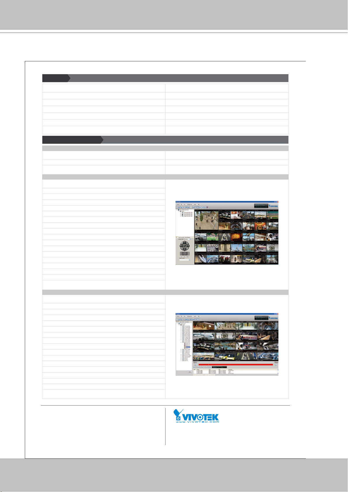
Technical Specications
Features
• Client/Server for Remote Video Management
• Real-time 32-channel Live Video Monitoring
• 16-channel Playback
• Flexible Layout Types
• Integrates with All VIVOTEK Network Cameras
• Supports Multiple Streams for Live Viewing and Recording
• PTZ/ePTZ Function Control by Control Panel & Mouse
Technical Specifications
ST7501 Server
• Serves as a video management site
• Performs 32-channel video recording
• Provides recording in multiple hard disks
ST7501 LiveClient
• Login to the ST7501 server
• Controls the server functions
• Manages user accounts of the server
• Edits the recording groups of the server
• Provides powerful monitoring window
• Dual screens for maximum 32 channels simultaneous monitoring
• 1x1, 2x2, 1+5, 3x3, 1+12, 4x4, 5x5, 1+31, 1P+2, 1P+6, 1P+8 monitoring layouts
• Multiple video viewing pages and page switching
• Supports convenient evidence exporting
• Exports media files of recorded video
• Supports snapshot and print out
• Supports convenient multiple monitor switching
• Provides PTZ operation panel for PTZ camera control
• Remote configuration for network cameras
• Log settings for security concern
• Event pop-up window based on event triggers
• Instant Replay & Playback on LiveClient
• Auto Stream Size Function for Reducing Display Loading
ST7501 Playback
• Login to the ST7501 server
• Browses the database of recorded video from the server in day base
• Provides convenient playback window
• Maximum 16-channel playback
• 1x1, 2x2, 1+5, 3x3, 1+12, 4x4 playback layouts
• Supports powerful playback functions
• 1/8, 1/4, 1/2 slow-down playback
• 2, 4, 8, 16, 32, 64 speed-up playback
• Supports convenient evidence exporting
• Exports media files of recorded video
• Supports snapshot and print out
• Supports convenient multiple monitor switching
• Powerful search engine
• Time Search
• Event Search
• Bookmark Search
• Log Search
Distributed by:
• Easy Snapshot & Export Functions
• Effective & Reliable Event Trigger Management
• Overall Device Management through Intuitive E-map Feature
• Two-way Audio, Multi-channel Audio Broadcast
• Instant Replay & Playback on LiveClient
• Auto Stream Size Function for Reducing Display Loading
• Directly Set up Basic Parameters for Cameras
• Feeds live video to the local/remote LiveClient users
• Feeds recorded video to the local/remote Playback users
• Zero waiting database recovery after unpredictable crash or power failure
32-channel Live Video Monitori ng
16-channel Playback
All specications are subject to change without notice. Copyright © 2013 VIVOTEK INC. All rights reserved.
10 - User's Manual
VIVOTEK INC.
6F, No.192, Lien-Cheng Rd., Chung-Ho, New Taipei City, 235, Taiwan, R.O.C.
|T: +886- 2-82455282|F: +886-2-82455532| E: sales@vivotek.com
VIVOTEK USA, INC.
2050 Ringwood Avenue, San Jose, CA 95131
|T: 408-773-8686| F: 408-773-8298| E: salesusa@vivotek.com
Ver 1.0
Page 11

VIVOTEK - A Leading Provider of Multimedia Communication Solutions
Server Functionality
Serves as a remote video management site for all the logged in clients
32-channel video recording
Store recorded data onto multiple hard/network disks
Live video for the local/remote LiveClient users
Recorded video for the local/remote Playback users
Zero latency database recovery
To congure the server, you should use ST7501 LiveClient to log in. The convenient and intuitive
user interface in ST7501 LiveClient will enable you to edit the settings of the target server.
User's Manual - 11
Page 12
VIVOTEK - A Leading Provider of Multimedia Communication Solutions
LiveClient Functionality
Server function control
User account management
Recording storage management
Recording schedule management
Recorded data backup
Event trigger management
Flexible video live view layout
Dual screens for a maximum of 64 or more channels for simultaneous monitoring
1x1, 1P+2, 2x2, 1+5, 1P+6, 3x3, 1P+8, 1+12, 4x4, 5x5, 1+31 monitoring layouts
1P+2, 1P+6, and 1P+8 Panoramic PTZ layouts
Multiple video viewing pages
E-map for overall management
Network storage for recorded video
Convenient switching among multiple monitors
PTZ / E-PTZ operation panel for camera control
Supports two way audio
Instant playback for event recording
Instant replay for immediate playback
Supports joystick control
Remote configuration for network cameras
12 - User's Manual
Page 13
VIVOTEK - A Leading Provider of Multimedia Communication Solutions
Playback Functionality
Browse the database of recorded video from the server
Flexible video playback layout
Maximum 16 channels with simultaneous playback
1x1, 2x2, 1+5, 3x3, 1+12, 4x4 video playback layouts
Supports powerful playback functions
1/8x, 1/4x, 1/2x slow-down playback
2x, 4x, 8x, 16x, 32x, 64x video playback speed
Supports convenient evidence and data exporting
Export media files of recorded video
Supports snapshot and print out
Supports convenient switch among multiple monitors
Search engine:
Time search
Event search
Bookmark search
Log search
Playback while recording
User's Manual - 13
Page 14
VIVOTEK - A Leading Provider of Multimedia Communication Solutions
Minimum System Requirements
Before installing the software, please make sure your system meets the following recommended
minimum system requirements.
If you would like to install ST7501 Server only, please follow the requirements as below:
Server
Operating System
Recording Channels Below 32 CH 32 ~ 64 CH 64CH
CPU
RAM 2 GB or above 4GB or above 4GB or above
Network Interface Card Ethernet, 1 Gbit recommended
Graphics Adapter
Hard Disk Type SATA, SCSI, SAS (7200 rpm or faster) in NTFS format
Hard Disk Space 750 GB free *
• The specications is based on following camera settings: 1920 x 1080, 4Mbps, H.2644
• The test result is base on the JBOD conguration, and the RAID conguration will provide different
result. Software RAID will reduce the VMS performance.
Windows Server 2000, 2003, 2008 / Windows XP Professional (32 and 64 bit),
Windows Vista Business (32 and 64 bit), Windows 7 (32 and 64 bit)
®
2nd Generation Intel
Core™ i3 Processors
2nd Generation Intel®
Core™ i5 Processors
2nd Generation Intel®
Core™ i7 Processors
DirectX 9 compatible 1GB graphics card
If you would like to install both the server and client programs, please follow the requirements as
below:
LiveClient and Playback
Operating System
Channels 8 CH 16 CH 24 CH
CPU
RAM 2 GB or above 4GB or above 4GB or above
Windows Server 2000, 2003, 2008 / Windows XP Professional (32 and 64 bit),
Windows Vista Business (32 and 64 bit), Windows 7 (32 and 64 bit)
®
2nd Generation Intel
Core™ i3 Processors
2nd Generation Intel®
Core™ i5 Processors
2nd Generation Intel® Core™
i7 Processors
Network Interface Card Ethernet, 1Gbit recommended
Graphics Adapter
Hard Disk Type SATA, SCSI, SAS (7200 rpm or faster) in NTFS format
Hard Disk Space 750 GB free *
• The specications is based on following camera settings: 1280 x 1024, 2Mbps, H.264
• 3MP sheye camera requires 1 channel decoder.
• 5MP sheye camera requires 1.5 channel decoder.
If you install the Server & Client (LiveView/Playback) in the same PC, please refer the CPU load to select
the display channel.
14 - User's Manual
DirectX 9 compatible 1GB graphics card
Page 15

VIVOTEK - A Leading Provider of Multimedia Communication Solutions
Only users with Administrator privileges can install or use ST7501 on a Windows Vista system.
The required hard disk space will depend on the video settings, the number of network cameras and recording
group settings. Please add more hard disks if you want to extend the system.
Below are approximate numbers for a week-long recording. The actual storage space required also depends on
imaging parameters, e.g., a complex retail environment that involves many moving objects requires more pixel
data to be transmitted over network than a simple environment such as a parking lot.
32-CH, VGA, about 1 week recording: 750 GB
32-CH, 2-megapixel, about 1 week recording: 2TB x 2
User's Manual - 15
Page 16

VIVOTEK - A Leading Provider of Multimedia Communication Solutions
Software Installation
Installing the Software
1. Run ST7501_Setup.exe on your computer. Click I ACCEPT the License Agreement and specify a
location to install the program.
2. Select the items you want to install, then click Next to continue.
If you want to install both Server component and Client components, please follow the steps below to
install the database.
Server component
Client components
3. Assign a username and password for the Server and click Next to continue.
Please record the user name and password for login later.
16 - User's Manual
Page 17
VIVOTEK - A Leading Provider of Multimedia Communication Solutions
4. Install a database on your server. There are two options--PostgreSQL (8.2 version or above) or SQL
server (
2005 express version or
above). In order to avoid conflicts among different databases, we
suggest you remove the original database from your host. Then follow the instruction below to install
PostgreSQL or SQL server.
PostgreSQL
Please note that PostgreSQL may interrupt an antivirus program.
Follow the steps below to install PostgreSQL Server:
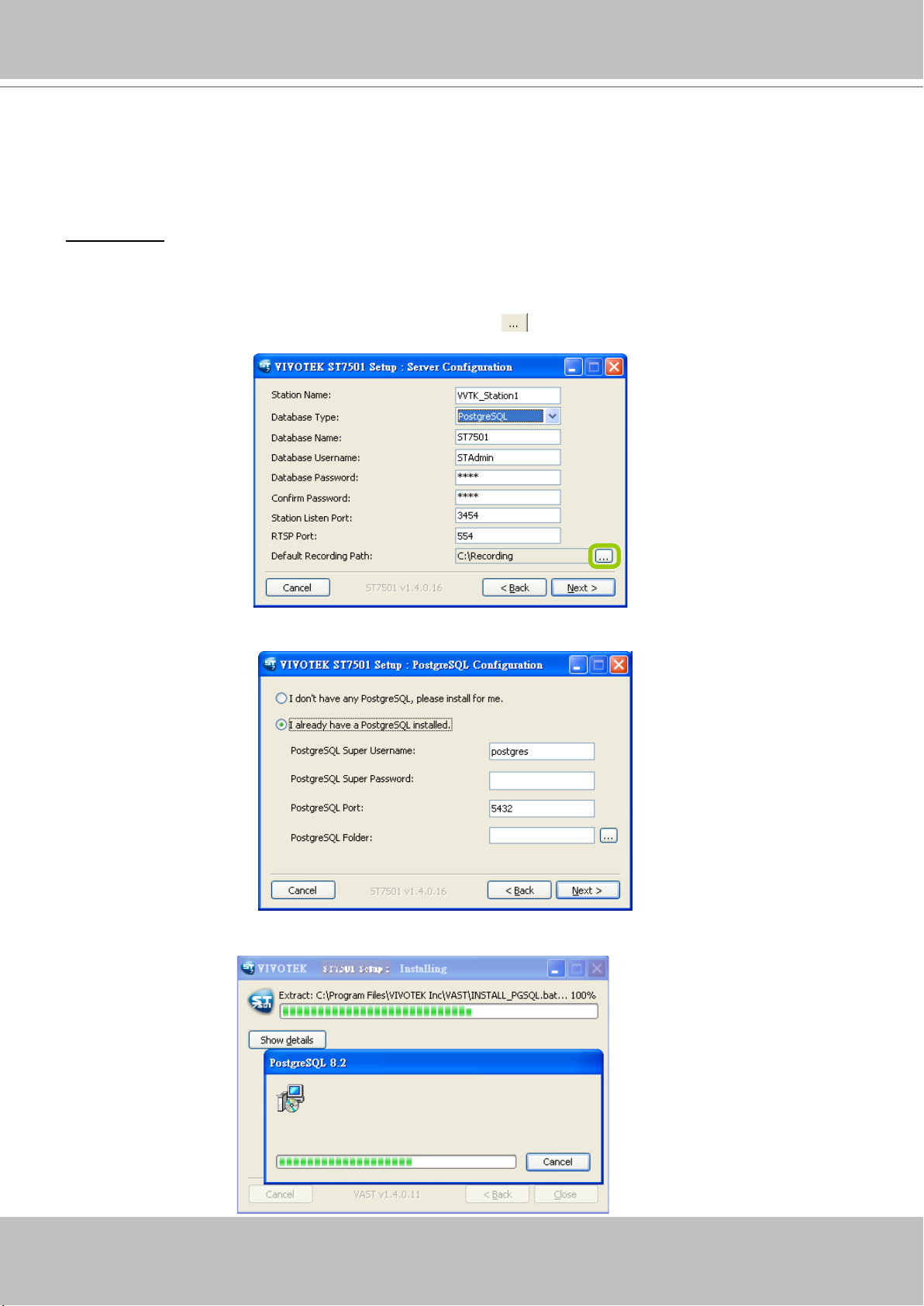
a. Select PostgreSQL from the drop-down list and assign a password. The server will by default store the
recorded media le under c:\Recording. Click Browse
to change the path if you plan to store the
video data to another folder. Then click Next to continue.
b. If you do not have PostgreSQL, select the first option to begin the installation.
If you already have
PostgreSQL installed on your host, select the second option to enter the related information.
c. Wait for the installation process to complete, then click Close to exit the installation program.
User's Manual - 17
Page 18
VIVOTEK - A Leading Provider of Multimedia Communication Solutions
SQL Server
Follow the steps below to install SQL Server:
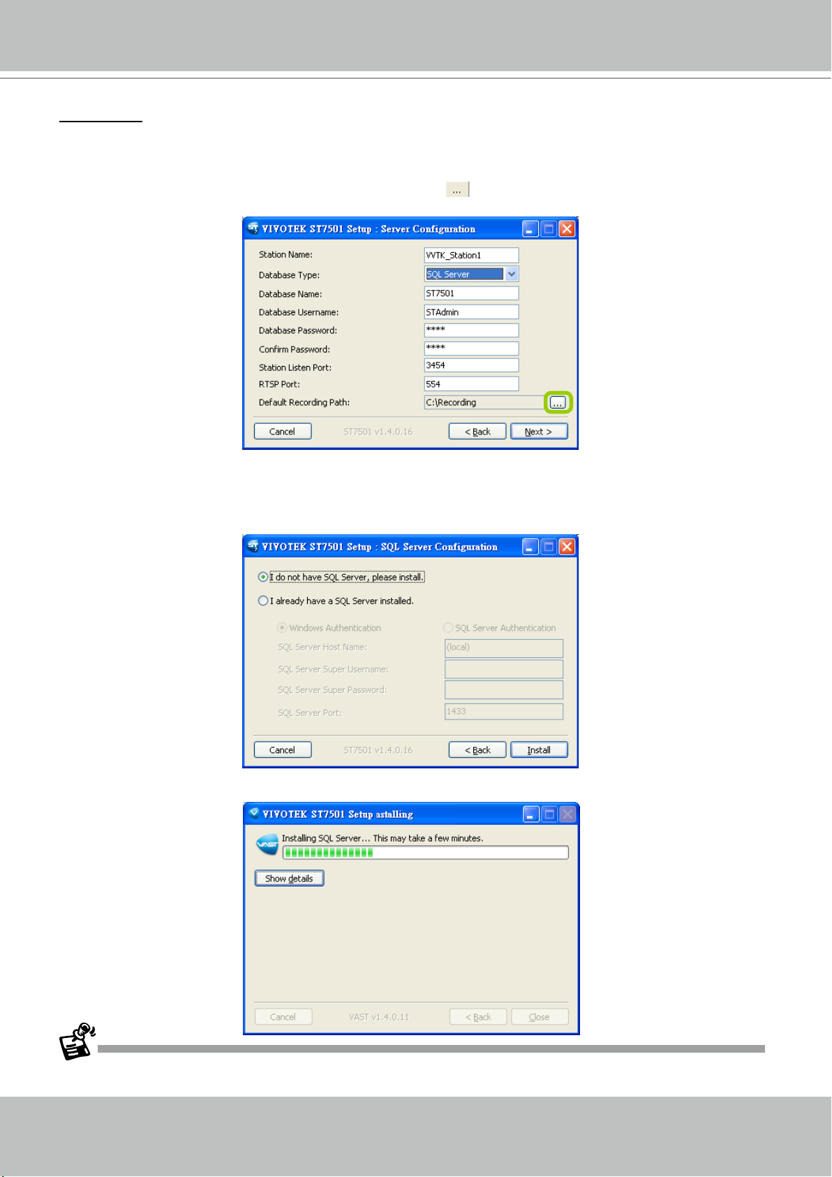
a. Select SQL Server from the drop-down list and assign a password. The server will by default store the
recorded media le under c:\Recording. Click Browse
to change the path if you plan to store the
data under another path. Then click Next to continue.
b. If you do not have SQL server, select the first option to begin the installation.
If you already have
SQL server installed on your host, select Windows authentification or SQL Server authentification.
(Username and Password may be necessary according to the settings when you install the SQL
server.) Click Install to begin the installation.
c. Wait for the installation process to complete, then click Close to exit the installation program.
Once you have created a user account for an ST7501 station, you can login to Server from any computer over the
network through LiveClient and Playback.
18 - User's Manual
Page 19
VIVOTEK - A Leading Provider of Multimedia Communication Solutions
ST7501 Server
Activating the Server
The server is a service program that will run automatically when your ST7501 station starts.
Users can also deselect the Auto launch option at windows startup on the Service Control
program tray. The program tray icon can be located on Windows tool bar.
How to Congure the Server
Please follow the steps below to congure the Server:
1. Find a local/remote computer that has installed LiveClient.
2. Activate LiveClient and login to the target Server.
3. Congure the server using the LiveClient user interface.
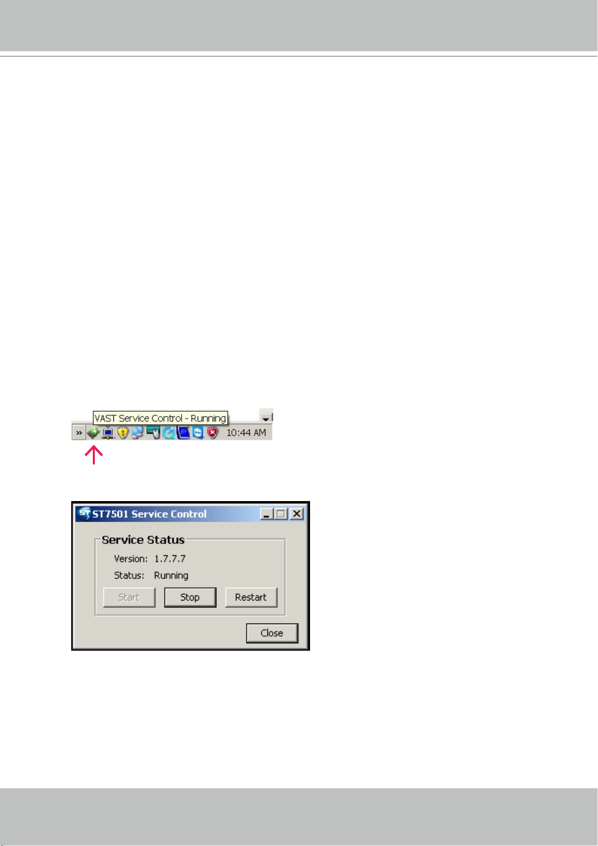
How to Stop/Reboot the Server
Please follow the steps below to stop/reboot the server:
1. Click on the ST7501 Service Control program tray icon in the toolbar.
2. There are 3 options: Start Service, Stop Service, and Restart Service. It’s selectable by a right-click on
the Service Control program tray icon.
User's Manual - 19
Page 20
VIVOTEK - A Leading Provider of Multimedia Communication Solutions
LiveClient Configuration
Activating the LiveClient and Logging in to a Server
LiveClient allows you to monitor live video from cameras managed by the software Server; it is
also the main user interface for server function control.
After installing the LiveClient program, please follow the steps below to activate LiveClient:
1. Run the LiveClient program.
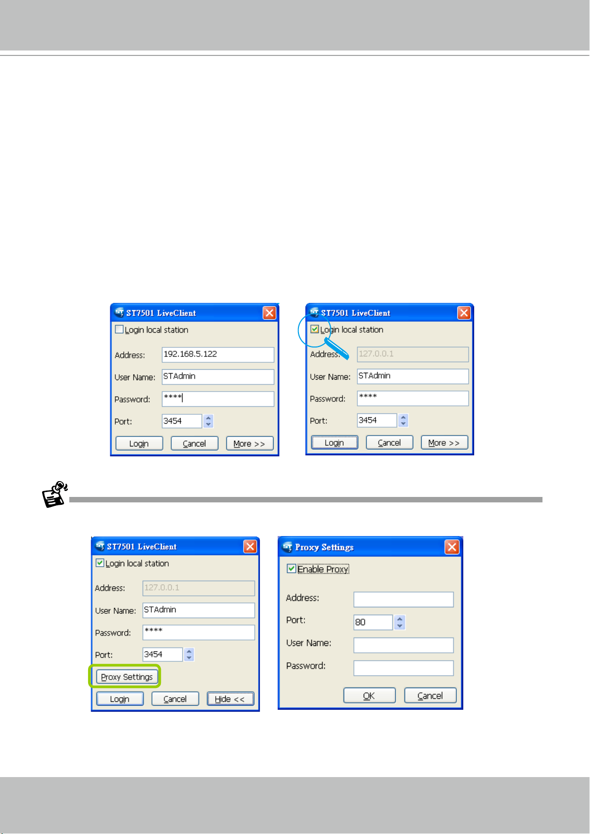
2. A Login window will pop up. Enter the information as shown below:
If you want to login to a remote Server, enter the IP Address, User Name, Password and the Com-
munication Port of the target server correctly. Click Login to log in to the target server.
If you want to login to a local host that is running Server, check the Login local station checkbox,
then the local IP Address will be displayed automatically. Enter the User Name, Password, and
Communication Port of the local server for login. Click Login to login to the target server.
3. The LiveClient monitoring window will prompt.
If your network environment need to set up proxy, click More >> to extend the login window, then click Proxy
Settings to open the dialog. Then enter related information to link to your proxy server.
Available functions of the LiveClient program will be enabled according to the role of your login account. For
more details about the privileges of the user account, please refer to How to Manage User Accounts on page
65.
20 - User's Manual
Page 21
VIVOTEK - A Leading Provider of Multimedia Communication Solutions
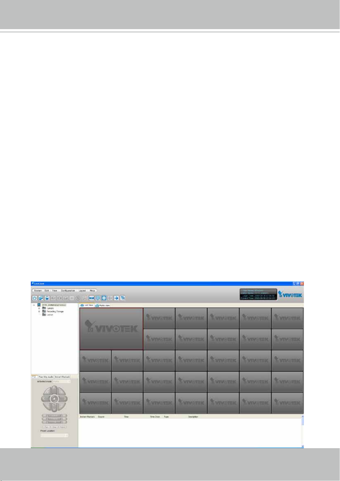
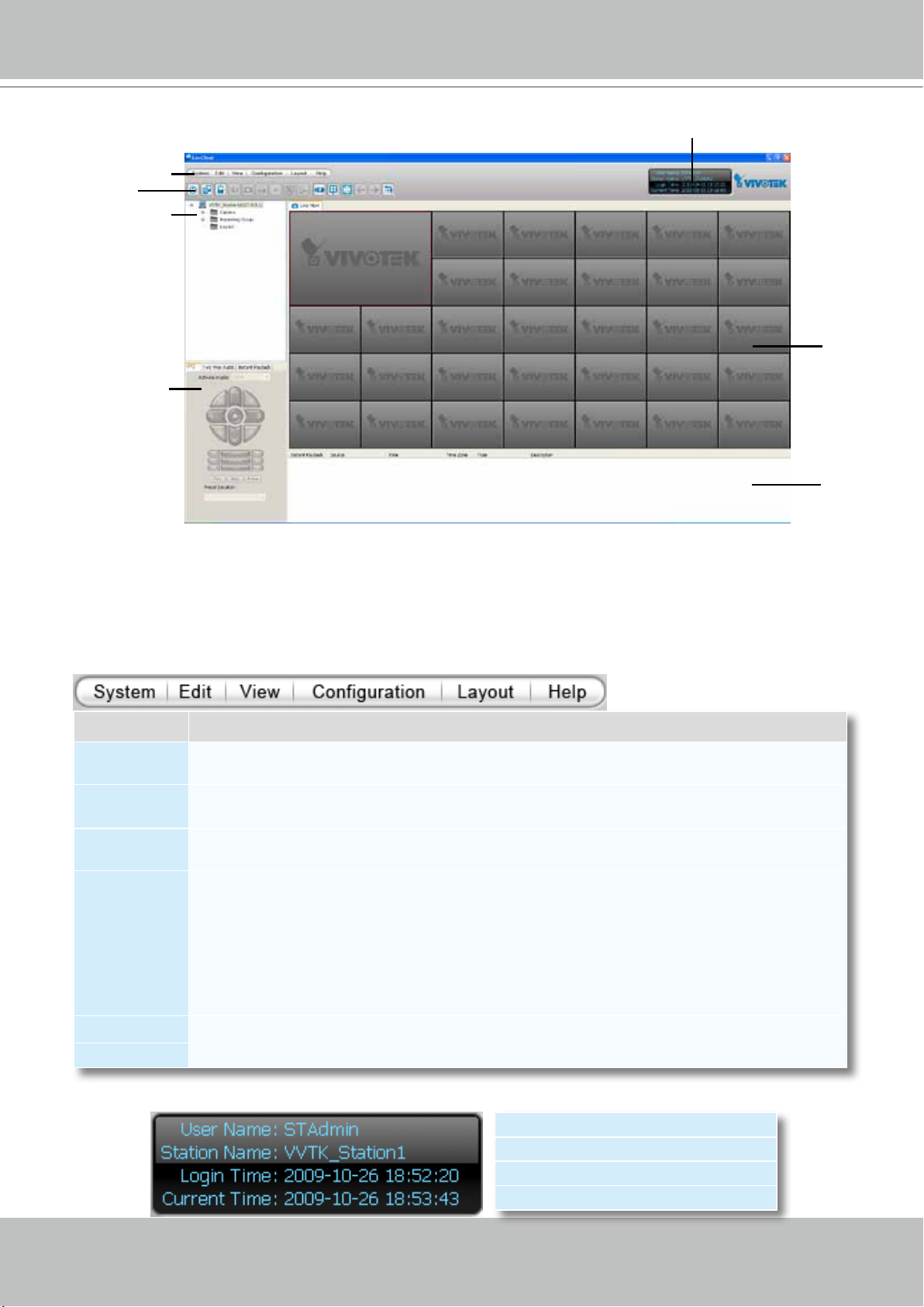
LiveClient User Interface
A
B
C
D
A. Menu bar B. Quick access bar C. Device tree
D. Camera control panel (PTZ / Two way audio / Instant Playback control panel)
E. Status panel F. Live video monitoring window G. Event window
E
F
G
Menu Bar
Menu Item Drop-down Options
System
Edit
View
Conguration
Layout Start Rotating (Stop Rotating) / Save to / Delete / Choose
Help About
Lock / Enable Click On Image (Disable Click On Image) / Language / Second View / E-map /
Launch Playback / Logout / Exit
Manually Begin Recording (Stop Manual Recording) / Snapshot / Print / Record to EXE (3GP,
AVI) / Snapshot Zoomed Image / Print Zoomed Image / Find
PTZ Panel / Two Way Audio Panel / Instant Playback Panel / Event Window / Full Screen /
Minimize / Matrix View
Camera Management (Insert Camera / Update Camera / Delete Cameras / Batch Insert
Cameras) / Station Management / User Management / Association Management / Event
Management / Station Settings (General Settings / Network Settings / Recording Storage
Settings / Recording Schedule Settings / Scheduled Backup Settings / Server Settings / Relay
Settings) / Client Settings (Snapshot Settings / Recording Settings / View Settings / General
Settings / Joystick Settings / Proxy Settings
Status Panel
User Name
Station Name (IP Address)
Login Time (yyyy-mm-dd hh:mm:ss)
Current Time (yyyy-mm-dd hh:mm:ss)
User's Manual - 21
Page 22
VIVOTEK - A Leading Provider of Multimedia Communication Solutions
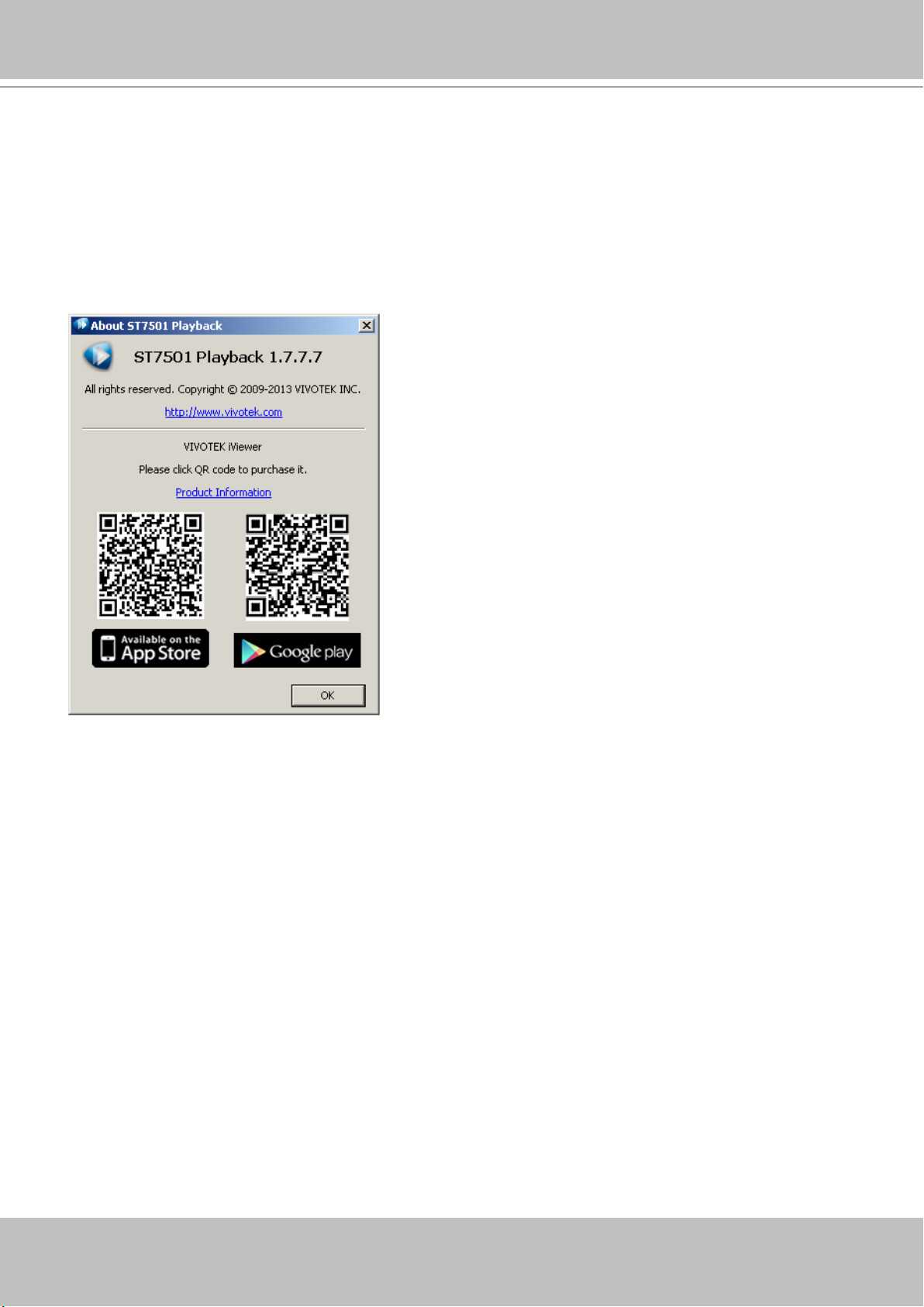
Help Panel
The Help panel provides software revision information and the access to the associated iViewer
software in either the iOS or Android version. You can also click on the License button to review
the number of cameras and manageable substations.
22 - User's Manual
Page 23
VIVOTEK - A Leading Provider of Multimedia Communication Solutions
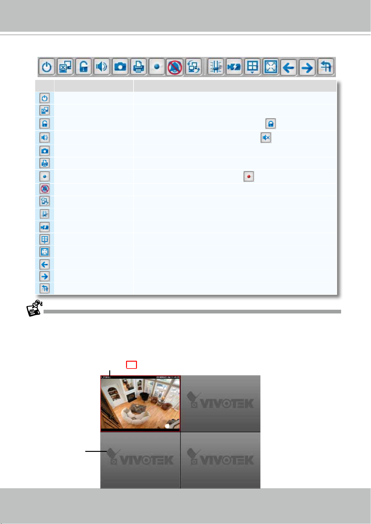
Quick Access Bar
Icon Function Description
Exit Exit the system
Logout Log out from the current station
Lock Click to Lock the system for security concerns (
Volume Adjust the audio volume of the current video ( Mute)
Snapshot Capture pictures from the focus live video cell
Print Print out the pictures of focus live view window or all live video cells
Record to Media Record media in EXE/3GP/AVI format (
Alert Sound Play sound when an event triggers
Switch Screen Switch the current window to another screen
Adjust SVC Level Dynamically adjust the SVC control over frame rates
Remove All Connections Remove all live videos from the live view window
Layout Change the layout of the live view window
Full Screen Maximize the live video cell
Page Up Switch to the previous live view page
Page Down Switch to the next live view page
Start / Stop Rotating Start or stop live view layout rotating
Recording Media)
Unlock the system)
Some buttons will be disabled if the selected devices do not support the corresponding functions.
Live Video Monitoring Window
The "VIVOTEK" logo is displayed where no camera has been assigned to a video cell.
The red frame ( ) represents the current selection.
Video Cell
User's Manual - 23
Page 24
VIVOTEK - A Leading Provider of Multimedia Communication Solutions
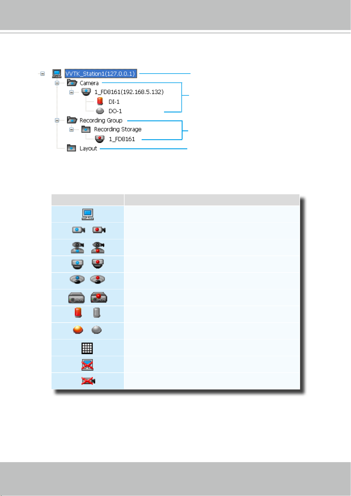
Hierarchical Management Tree
Root Station Name (IP address)
Connected devices listed under the root station
Camera name (IP Address)
Connected devices that have been assigned to the
default recording storage
Layout list
Icon Description
A station (The host that’s installed with ST7501 Server)
/
/
/
/
/
/
/
VIVOTEK xed network camera
Red dot signies that the camera is recording.
VIVOTEK PTZ network camera
Red dot signies that the camera is recording.
VIVOTEK dome network camera
Red dot signies that the camera is recording.
VIVOTEK sheye network camera
Red dot indicates that the camera is recording.
VIVOTEK video server
Red dot signies that the video server is recording.
Digital input on / off
Digital output on / off
A layout of the live monitoring window
A station that’s not able to be connected currently.
24 - User's Manual
A device that’s not able to be connected currently.
Page 25
VIVOTEK - A Leading Provider of Multimedia Communication Solutions
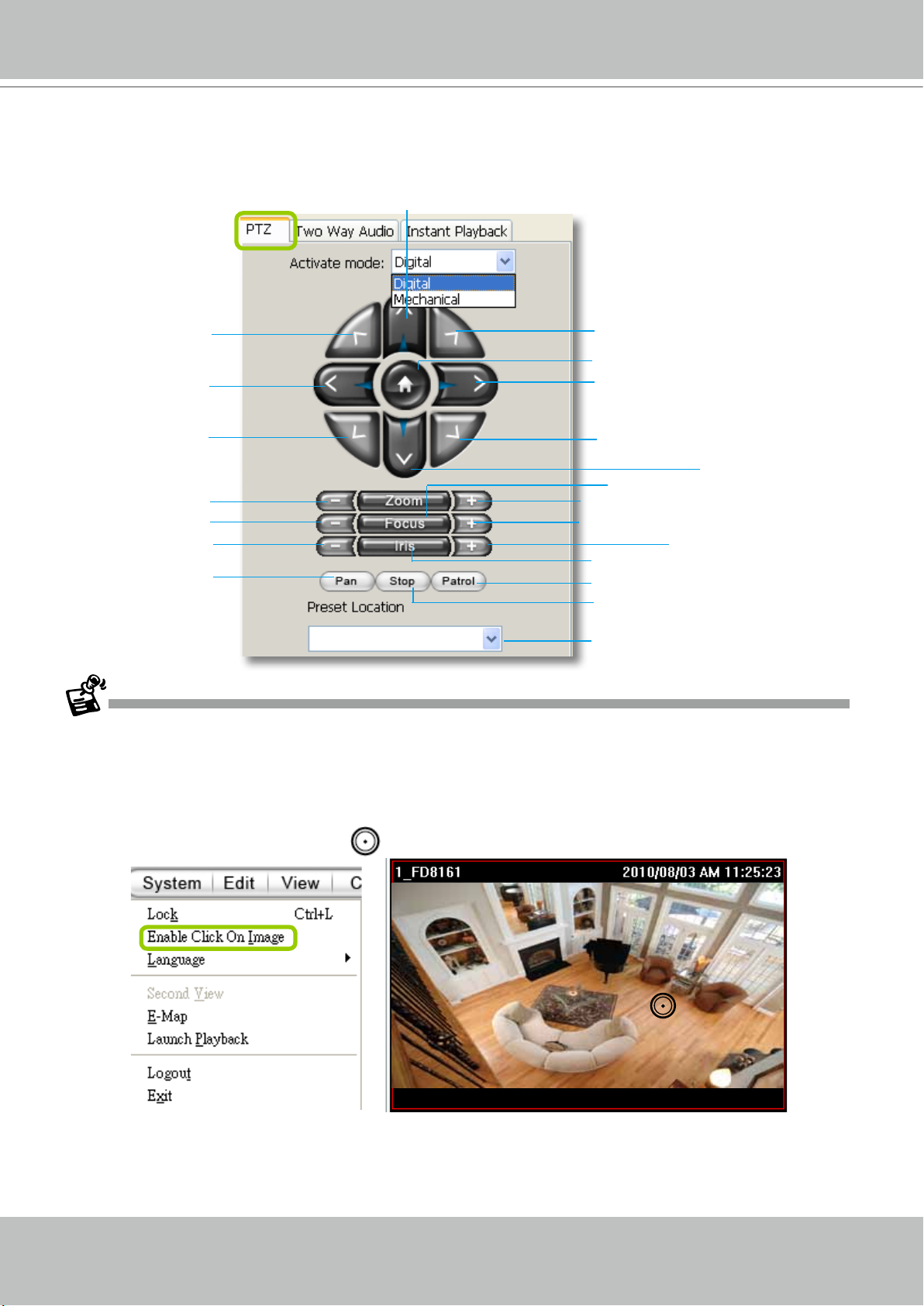
Camera Control Panel
Pan/Tilt/Zoom (PTZ) Control Panel
Up
op left
T
Top right
Return to home position
Left
Bottom left
Right
Bottom right
Down
Auto focus
Zoom out
Focus near
Close
Zoom in
Focus far
Open
Auto iris
Start to auto pan
Start to auto patrol
Stop auto panning/patrolling
Drop-down list of preset positions
There are two types of PTZ control: Digital (E-PTZ for megapixel cameras) and Mechanical (PTZ cameras or
fixed cameras with camera control via RS-485). If the connected cameras support PTZ/E-PTZ function, the
PTZ option(s) will appear on the drop-down list. For detailed camera control settings, please refer to the user's
manual of VIVOTEK network camera .
Click System > Enable Click On Image to use the mouse for the control of the PTZ and e-PTZ functions in the
video cells for linked cameras. An icon
will appear in the video cell as shown below.
You can control the PTZ function through joystick as well. For more information regarding to the joystick
conguration, please refer to instructions on page 135.
User's Manual - 25
Page 26

VIVOTEK - A Leading Provider of Multimedia Communication Solutions
In addition to the PTZ panel, the following hot key combinations are also available:
Ctrl + NumPad (PTZ control)
Up Ctrl + 8
Left Ctrl + 4
Home Ctrl + 5
Right Ctrl + 6
Down Ctrl + 2
Focus (Far - Near) Ctrl + 1 Ctrl + 3
Zoom (Out - In) Ctrl + 7 Ctrl + 9
Pan Ctrl + /
Stop Ctrl + *
Patrol Ctrl + -
Preset locations (pre-
congured by users)
Full screen Ctrl + F
Single view Ctrl + V
Previous layout page Alt + PageUP
Next layout page Alt + PageDown
First layout page Alt + Home
Last layout page Alt + End
Snapshot Ctrl + S
Stop alarm Ctrl + A
Mute audio from
current stream
Start/ Stop rotation Ctrl + O
Ctrl + 0~9 (number keys above the
alphabetic keys)
Ctrl + M
26 - User's Manual
Page 27
VIVOTEK - A Leading Provider of Multimedia Communication Solutions
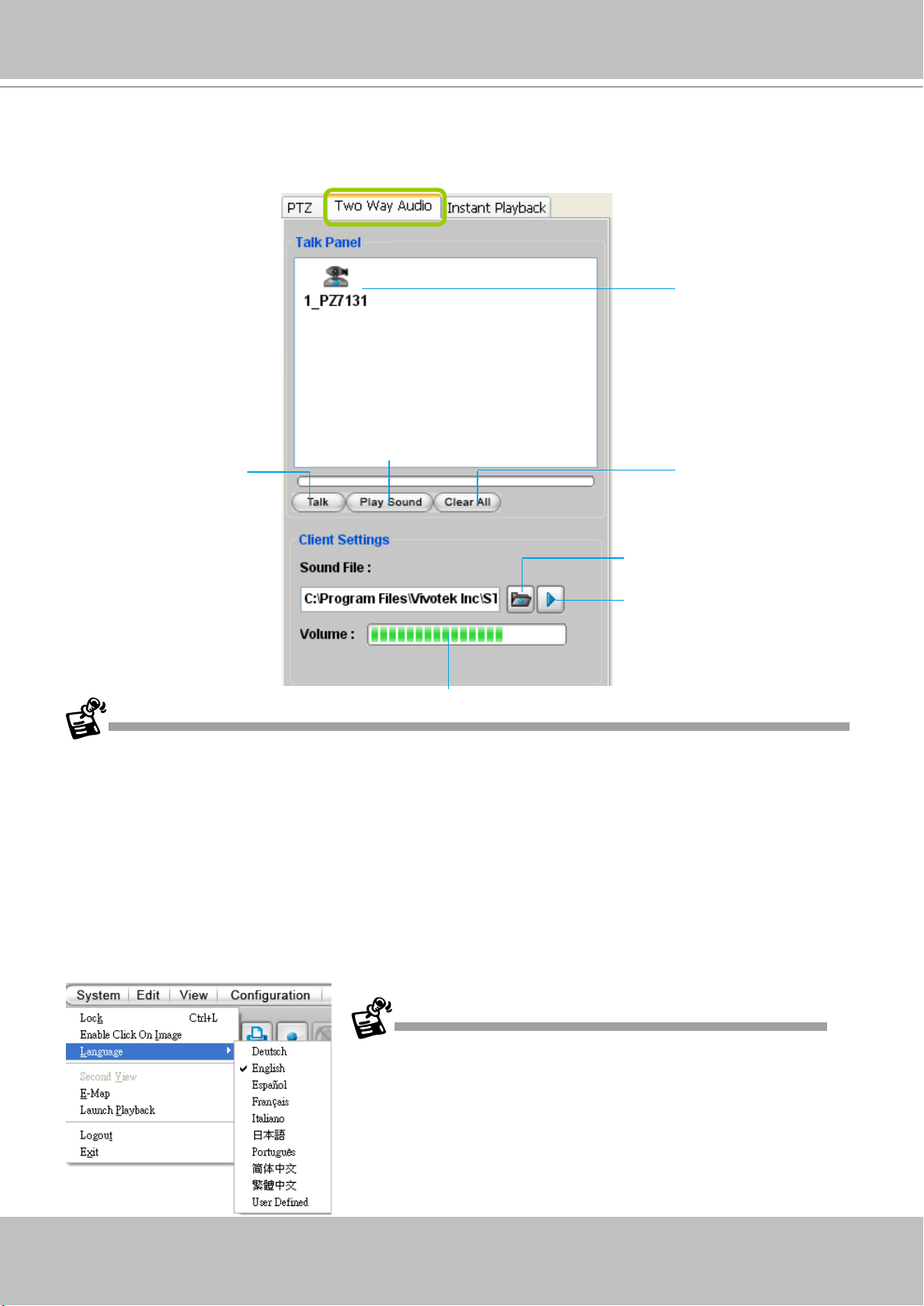
Two Way Audio Control Panel
The two way audio function allows the user to remotely communicate with people nearby the
network camera.
Selected device that
can use the two way
audio function
Click to play sound from the camera
Click to talk
Remove all cameras
from the Talk Panel
Select sound from the
le list
Click to play the selected
sound on the client's side
Click to adjust volume
For detailed information about How to Use the Talk Panel, please refer to page 110.
Only cameras that come with the two way audio function can be added to the Talk Panel.
Language Selection
The software currently supports multi-lingual user interfaces including:
Français, Italiano,
日本語
, Português,
簡体中文
繁體中文
,
. If you want to select another language for
English, Deutsch, Español,
the interface, please click System > Language on the menu bar to select the desired language.
Please note that if you want to change the language option, a message will prompt to remind
you to restart the system.
If you want to use "User Dened" language, please prepare images and
language strings, and upload the les to the following folders:
...\ST7501\Client\LiveClient\language\zz_UD (language string)
...\ST7501\Client\LiveClient\image (images)
User's Manual - 27
Page 28
VIVOTEK - A Leading Provider of Multimedia Communication Solutions
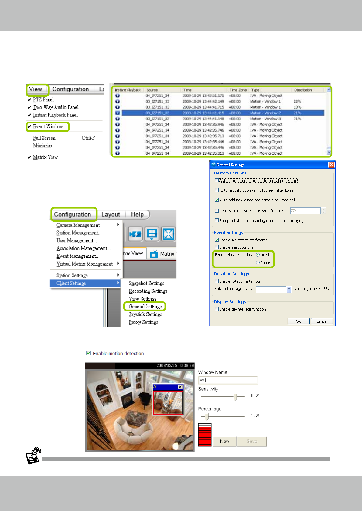
Event Window
Click View > Event Window to open a window showing the real-time information for event
triggers. If you want to hide this window, deselect this option on the menu bar.
Event Window
The default event window is fixed on the bottom
of the LiveClient. If you want to change the event
window as a popup page, please click Conguration
> Client Settings > General Settings to switch the
modes.
The Type eld in the event window shows the event category and another eld Description displays
the percentage of motion in the detection window. You can go to the Conguration setting page of the
connected device to set the percentage.
Video(TCP-AV)
For more information about DI/DO settings, please refer to Association Management on page 70.
28 - User's Manual
Page 29
VIVOTEK - A Leading Provider of Multimedia Communication Solutions
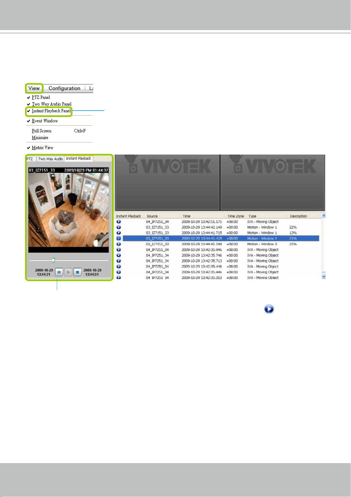
Instant Playback
Check View > Instant Playback to open the window on the panel. The entries listed in the
Event panel are the short recordings made from triggered events.
Uncheck this item if you want to hide this window.
Instant Playback Window with a slide bar, play, pause, and stop function
The recorded media that was triggered by an event will be indicated with an
icon.
You can double-click an event on the list to playback the recorded video. Each event contains
about 20-seconds recorded video clip. (The default recording data of an event is 20 seconds.
For more information about event recording, please refer to page 83.)
User's Manual - 29
Page 30
VIVOTEK - A Leading Provider of Multimedia Communication Solutions
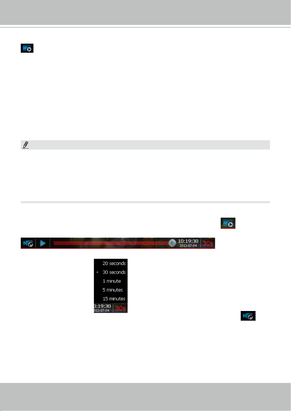
Instant Replay
If a camera is currently recording to the NVR, then a Replay button will be available at the
lower left corner of its view cell. This allows you to immediately retrieve the video recording in
the past 30 seconds.
The Instant Replay function enables you to quickly retrieve videos of what has just happened (20
seconds to 15 minutes ago), without the need to open the Playback utility for the past videos.
Prerequisites for Instant Replay:
1. The function is enabled by default, only available on a LiveClient installed on a PC.
2. There must be recorded videos of the immediate past. If the video streams from a camera
were not recorded, you can not retrieve videos using the Instant Replay function.
NOTE:
1. When using the Instant Replay function and you change the stream number on a video cell,
the Instant Replay will be interrupted.
2. The Instant Replay will also be interrupted when the time comes for a rotation of Live View
pages. For example, if you have multiple Live View pages and you set up a rotation of these
pages by every 10 seconds, page swap (rotation) still has a higher priority even if you are
viewing the Instant Replay.
How to Use:
1. On a selected view cell, mouse over to the lower left corner. A Replay icon
will appear.
2. Click on it to display the Replay control bar. Click on the play button.
3. The default queue length is 30 seconds. You can click on the number on the right to change
the queue length.
The queue length configuration stays with the
view cell, and it will not go unless you remove
and insert the camera again.
4. To stop the Replay and return to the Live View, click on the Return to Live button.
5. On a Replay view cell, you can apply the same Snapshot, Print, Single view and Full screen
control as those on a normal view cell. You can also right-click to display the Display Mode
and Video Enhancement functions.
Click and drag the playhead to skip or move to a different point in time on the playback.
30 - User's Manual
Page 31

VIVOTEK - A Leading Provider of Multimedia Communication Solutions
An active Replay view cell is indicated by the Replay text indicator and the time of occurrence
of the current playback.
To change the default Replay settings, open the Conguration > Client Settings > General
Settings menu.
Audio Control
The audio function will be enabled if the device is equipped with an internal or external
microphone. For detailed audio control settings, please refer to page 138.
User's Manual - 31
Page 32

VIVOTEK - A Leading Provider of Multimedia Communication Solutions
How to Manage Devices
Please follow the steps below to open the Camera Management window:
a. Select the station from the hierarchical management tree.
b. Click Conguration > Camera Management on the menu bar (or right-click the station, then select
Camera Management).
c. Then you can choose to insert, update, delete, or batch insert cameras.
b
a
a
b
Insert Cameras
Please follow the steps below to add devices to a station:
a. Click Conguration > Camera Management > Insert Camera on the menu bar (or right-click the
device/station, then select Camera Management > Insert Camera).
b. The Camera Management - Insert window will pop up. The device tree managed by the station will
be displayed in the left Camera List window.
c. Enter the Camera Name, IP address (or you can enter an IP address and check Auto to get a
camera name automatically) and congure the Connection Settings.
If the camera is on the LAN, you can click Search Camera to detect all VIVOTEK network
cameras on the LAN. A Camera List window will pop up and show a list of detected cameras on
the LAN. On the top of Camera List window, you can select "List the cameras which are not
inserted" or "List all cameras". The items listed below will then change accordingly. You can click
Mac, IP Address, Model, HTTP port to sort the items. Then select a camera from the list to insert
to the station.
The streaming protocol determines how the live video stream is sent from the camera to the local
computer. Please refer to the note on the next page for a detailed description of each transmission
protocol. Specify the recommended live monitoring stream for the device. If you want to change the
live viewing stream, please refer to the next page to update the camera settings. Or you can right-
click the desired cell, then select a desired stream. Please refer to Dual / Multiple Streams on page
50 for a detailed illustration.
Click Detect Model to detect the device. The Model Name and MAC Address of the device will
automatically be displayed in the respective elds if the connection is successful.
d. If you want to make sure you are connected to the target device, click Connection Test to preview the
live video from the device.
32 - User's Manual
Page 33

VIVOTEK - A Leading Provider of Multimedia Communication Solutions
c
d
c
c
If you want to use "HTTPS Port", please enable the HTTPs settings on the conguration page of the Network
Camera rst.
The characteristics of each protocol are shown in the following table:
Protocol Description
UDP uses a simple transmission model without implicit hand-shaking dialogues for guaranteeing
reliability, ordering, or data integrity. Thus, UDP provides an unreliable service and data grams may
UDP
TCP
arrive out of order, appear duplicated, or go missing without notice. This protocol allows for almost
real-time audio and video streams. However, network packets may be lost due to network burst
trafc and images may be obscured. Activate UDP connection when occasions require time-sensitive
responses and video quality is less important.
TCP provides the service of exchanging data reliably directly between two network hosts, whereas IP
handles addressing and routing message across one or more networks. In particular, TCP provides
reliable, ordered delivery of a stream of bytes from a program on one computer to another program
on another computer. This protocol guarantees the delivery of streaming data and thus provides
better video quality. The downside with this protocol is that the real-time effect is worse than that with
UDP for a narrower bandwidth.
HTTP
HTTPS
HTTP is a networking protocol for distributed, collaborative, hypermedia information systems. It’s the
foundation of data communication for the World Wide Web. This protocol allows for the same quality
as TCP and the users need not open a specic port for streaming under some network environment.
Users inside a rewall can utilize this protocol to allow streaming data through.
This protocol enables authentication and encrypted communication over SSL (Secure Socket Layer),
which protects streaming data transmission over the Internet on higer security level.
User's Manual - 33
Page 34

VIVOTEK - A Leading Provider of Multimedia Communication Solutions
Time
e. Congure Recording Settings:
Recording Stream: By default, the stream source of the recording stream is stream 1, if you want to
change it later on, please refer to the previous page to update the camera settings.
Pre-event time: Enter a number to decide how much time to record before an event is triggered.
Post-event time: Enter a number to decide the duration of recording after an event is triggered.
e
pre-
10 sec.
Pre-event time
Trigger Activation
Post-event time
post-
10 sec.
For example: If both the Pre-event time and Postevent time are set to 10 seconds, a total of 20
seconds of video will be recorded if an event is triggered. This function is supported by the buffer area
of the server (time shift cache stream).
Activity Adaptive Stream (active if possible): Check
this item to enable activity adaptive stream recording
and time shift recording. For cameras combined
with time-shift cache stream and multiple streams
features, user can make use of activity adaptive
streaming for dynamic frame control.
If you check Activate Activity Adaptive Stream and
enable time-shift cache stream on the camera, the
Bandwidth
Bandwidth
I frame ---> Full frame rate ---> I frame
Activity Adaptive Streaming
for Dynamic Frame Rate Control
server will record full-frame-rate video only when an
event is triggered on the camera; otherwise, it will only
request the I frame data during normal monitoring,
thus effectively save lots of bandwidths and storage.
Continuous recording
Minimum pre-event time: Due to the limited cache memory on each network camera, the pre-event
time of time shift cache stream on camera may be very short. Then you can choose to set pre-event
recording on the server. For example: To set up a minimum of 5 seconds. If the cache memory of
the selected Network Camera can only support up to 3 seconds, the Server will switch to enable
pre-event recording for 5 seconds by itself, rather than requesting the time shift cache stream from
the network camera.
Please note that if you want to enable activity adaptive stream, we suggest you right-click the camera on the
heirarchical management tree > Camera Settings to open a managment session. Move to Conguraion > Media
> Audio and Video to activate "Time Shift Cache Stream" on the camera and select a stream source. This will
help record complete pre-event recording.
34 - User's Manual
Page 35

g
VIVOTEK - A Leading Provider of Multimedia Communication Solutions
f
i
g
f. The device will automatically be assigned to the default recording group. Deselect the item if you want
to cancel this setting.
g. When all settings are completed, click Insert to add the device to the station. The device will be
displayed under the Camera List on the left.
h. To insert additional devices to the station, repeat the above steps.
i. When completed, click Close to exit the camera management window.
j. Back to the main window, you will nd the newly-inserted devices displayed under the station and the
live video in the video cell.
User's Manual - 35
Page 36

VIVOTEK - A Leading Provider of Multimedia Communication Solutions
Enable SVC
If the camera to-be-added supports the latest SVC (Scalable Video Coding) feature, select the
SVC checkbox to enable the related control. The SVC feature enables streaming of videos for
multiple clients from one single set of layered IP packets. Designed for saving bandwidth and
CPU load on client stations, the frame rate of a video stream appearing through a view cell
can be individually adjusted. This feature applies when an administrator experiences unstable
video streaming due to the lack of network bandwidth, less-than-ideal hardware, or during an
occurence of network problems.
30fps
Client PC
25fps
Notebook
5fps
3G Cell Phone
SVC Packet
Network Camera
LAN
Server
LAN/WAN
Stream
on Demand
Stream
on Demand
Stream
on Demand
Stream
on Demand
60fps
NVR Storage
The server (rev. 1.6.1 and later) automatically negotiates with a camera and determines whether
a network camera comes with the SVC feature.
To congure the SVC-related feature:
1. When inserting a new camera into your conguration, select the streaming option, usually the
stream #1.
36 - User's Manual
Page 37

VIVOTEK - A Leading Provider of Multimedia Communication Solutions
2.
Right-click on the view cell of an SVC-enabled camera. Select SVC fps adjust bar.
3. A slide bar will appear above the view cell. Click and drag the slide bar. A numeric indicator
will display the current selection. See below for the frame rates represented by the numeric
indicator.
Indicator Frames per second (fps)
Maximum 30
7 26
6 22
5 18
4 12
3 8
2 4
1 1
Minimum 1/4
NOTE:
The SVC feature only applies to H.264 and MJPEG streams. It is not applicable to MPEG-4 streams.
Please refer to Conguration -> Media -> Video for individaul stream settings.
User's Manual - 37
Page 38

VIVOTEK - A Leading Provider of Multimedia Communication Solutions
If you have multiple SVC-enabled cameras, you can enable a collective setting via the Adjust
SVC level button on the tool bar. The frame rate selected here will then apply to all view cells on
the LiveClient console.
Please note that the SVC related setting can not take effect while the LiveClient station is
running the Layout Rotation. Stop the layout rotation before conguring the SVC function.
While you save your bandwidth for live viewing, you can still record full-frame-rate video by changing the
recording setting. For example, you can enable resource-saving SVC on stream #1 and congure stream
#2 to be recorded with full details, in terms of frame size, frame rate, and video quality.
38 - User's Manual
Page 39

VIVOTEK - A Leading Provider of Multimedia Communication Solutions
Insert a Video Server
1. Left-click on your station, and then right-click to display the Camera Management command.
Let your cursor stay on the command for a second and then move to the Insert Camera
command. Click on the command to open its conguration window.
User's Manual - 39
Page 40

VIVOTEK - A Leading Provider of Multimedia Communication Solutions
1
2
2. See below for the steps to insert a Video Server along with its subordinate cameras.
1
2
3
4
5
6
2-1. You can deselect the Auto checkbox to enter a name for the Video Server. If set to Auto and your
video server already has a name, that name will be displayed in your device list.
2-2. Enter the Address of the video server - or - use the Search
2-3. If you enter its address and it is found after you click on the Detect Model
Name and MAC Address will be listed.
2-4. Before you click the Detect button, you should enter the User Name and Password for access
to the video server. You should also confirm the Configuration Protocol, Configuration Port,
Streaming Protocol, and the rest of the networking parameters.
2-5. You may select or deselect the checkbox in front of the recording storage option - or - use the pull-
down menu to select the default group or a pre-congured storage group.
You might use the Connection Test button to verify if the stream comes from the device you prefer.
2-6. Click Insert to include the video server to your conguration.
The Video Server should now be listed on the Camera List.
You can also use the Search button to poll the local area network for VIVOTEK's devices. You can
select to list all cameras or list those that have not been included in your current conguration.
Click on a device, and its detailed information will immediately appear in the Camera Management
window on the left. For recording settings, please refer to page 34 as previously described.
button to open a Search window.
button, its Model
40 - User's Manual
Page 41

VIVOTEK - A Leading Provider of Multimedia Communication Solutions
Update Devices
Please follow the steps below to update a device via Camera Management window:
a. Click Conguration > Camera Management > Update Camera on the menu bar (or right-click the
device/station, then select Camera Management > Update Camera).
b. The Camera Management - Update window will pop up. The device tree managed by the station will
be displayed in the left Camera List window.
c. Select a device from the list you want to update. Its related information will automatically be displayed
in the corresponding fields in the Camera Management window. Then you can modify Connection
Settings and Recording Settings of the device.
d. After modifying the settings, you can click Connection Test to preview the live video from the device.
e. When all settings are completed, click Update to enable the settings.
a
b
c
d
e
User's Manual - 41
Page 42

VIVOTEK - A Leading Provider of Multimedia Communication Solutions
Delete Devices from the Server
Delete a device:
Right-click the device on the device tree, then select Delete. A dialog box will pop up. Click Yes to
delete the device along with the recorded data; click No to delete the device but retain the recorded
data; click Cancel to cancel the delete action.
Delete more than one device at a time:
a. Click Conguration > Camera Management > Delete Cameras on the menu bar (or right-click the
device/station, then select Camera Management > Delete Cameras).
b. The Delete Cameras window will pop up.
c. Select the devices you want to delete from the list, then click Delete.
d. A dialog box will pop up. Click Yes to delete the device along with the recorded data; click No to delete
the device but retain the recorded data; click Cancel to cancel the delete action.
e. When completed, click Close to exit the Delete Cameras window and return to the main window. The
deleted device will disappear from the station.
b
a
d
c
e
42 - User's Manual
Page 43

VIVOTEK - A Leading Provider of Multimedia Communication Solutions
Batch Insert Devices
Batch insert is a very useful function that allows user to search, filter, and import a row of
devices that are in the same LAN to an ST7501 station. The basic settings can also be applied
to those inserted devices simultaneously.
Please follow the steps below to batch insert devices to a station:
a. Click Conguration > Camera Management > Batch Insert Cameras on the menu bar (or right-
click the station, then select Camera Management > Batch Insert Camera).
b. The Batch Insert Cameras window will pop up. Then click Search to open the Search Camera
window.
c. On top of the Camera List window, you can select "List the cameras which are not inserted" or "List all
cameras". The items listed below will then change accordingly.
d. Use the 4 Filters to narrow down the range of the wanted cameras from the list.
IP Range: Type in a range of IP address to narrow down the list; the lter automatically applies after
you ll in a correct IP range.
c
b
d
User's Manual - 43
Page 44

VIVOTEK - A Leading Provider of Multimedia Communication Solutions
IP with prex: Type in the prex of the IP address to narrow down the list.
Model with prex: The user can type in the prex of the model name or the complete model name of
the cameras to narrow down the list.
MAC with prex: You can type in the prex of the MAC address of the cameras to narrow down the
list.
44 - User's Manual
Page 45

VIVOTEK - A Leading Provider of Multimedia Communication Solutions
e. When the list is ltered, you can select the cameras one by one or check Select All to add them to the
batch insert list. Then click OK to nish searching.
f. The selected cameras will be shown on the batch insert camera list with the camera information and
the connection status. When you click on a camera, a live view will show up on the right side for you to
identify the cameras on the list. If you want to remove a camera from the list, click the trash can icon to
delete it.
f
h
g
i
j
User's Manual - 45
Page 46

VIVOTEK - A Leading Provider of Multimedia Communication Solutions
g. At the bottom of the window, there is a eld for you to alter the camera settings including Connection
Settings and Recording Settings. You can apply the new settings to each camera on the list, or
click Apply to All to apply the same congurations to all the cameras. For more information about
Connection Settings and Recording Settings, please refer to Insert Device on page 32 for detailed
information.
h. Specify host: If you want to add a camera to the list, click Specify
Address to directly add a wanted camera. Click Add after lling in
the correct information. The camera will be added to the list of the
Batch Insert Camera window.
i. By default, all inserted devices will be applied to the default
recording group. Deselect the Add checkbox if you do not want to
assign the selected devices to the default recording group.
j. Click Insert when all the settings are done. Cameras will be added.
When you modify the camera settings, and when the connection information (User Name, Password, Conguration
Protocol, Conguration Port, and Streaming Protocol) does not match the current network environment, the camera
will be disconnected and the status of the camera will become “Camera cannot be found” as shown below.
46 - User's Manual
Page 47

VIVOTEK - A Leading Provider of Multimedia Communication Solutions
Camera Conguration
The Camera Conguration function group provides immediate access to the video streaming and other
settings without the need to open a web console. The function group is accessed by selecting a camera
on the device tree, and right-click to select Camera Management > Camera Conguration.
FOV (Field of View)
The FOV configuration is available for 5 megapixel cameras (such as FE8172, IP8372, and IP8172P),
which allows you to crop a portion of the image captured by the sensor. The FOV setting applies in the
scenario where you do not need all of the video a camera can capture. For example, when shooting a
parking lot where the upper half of the image is the sky. Cropping a field of view can help save bandwidth
and reduce the requirements for storage space.
User's Manual - 47
Page 48

VIVOTEK - A Leading Provider of Multimedia Communication Solutions
Video
This tabbed window privides access to the selection of the live view stream, its compression codec,
frame size, max. frame rate, and video quality. Note that the Constant Bit Rate methodology can be
used to ensure that the size of video stream does not exceed a preferred threshold, regardless of the
complexity or the changes of pixels in the image. You should use a maximum of 1080P as frame size
and 6Mbps as constant bit rate for video streams managed by this system.
Audio
If audio feed is preferred, configure the audio codec type and operating mode in here.
48 - User's Manual
Page 49

VIVOTEK - A Leading Provider of Multimedia Communication Solutions
Remote Focus
For cameras supporting the remote focus feature, such as the FD8362E that comes with a motorized
lens, this window provides finetune buttons and full-range scan fucntion to help reach the best image focus.
NTP Settings
If cameras’ real time clocks are set to be synchronized with a time server, enter the NTP server’s address or domain name and specify an Updating interval. If you select the “Synchronize camera time with
system automatically” checkbox during the initial setup, the NTP server IP will be the PC’s IP.
Always remember to Save your configuration before leaving this window. You can also use the “Copy
settings to” button below to duplicate your current settings to adjacent cameras.
User's Manual - 49
Page 50

VIVOTEK - A Leading Provider of Multimedia Communication Solutions
View Live Videos
The server will automatically add a newly-inserted device to the video cell for live viewing.
You also can double-click the target device or drag-and-drop the target device from the
hierarchical management tree window to the video cell.
Dual / Multiple Streams
For dual-stream devices, you can right-click on the focused cell to select stream 1 or stream 2. For
multiple-stream devices, you can select from stream 1 ~ stream 4.
Fisheye Display Modes
By default, an oval view is displayed when a fisheye camera is successfully connected. To
display Regional, Panoramic, or the combination of different views, right-click on a fisheye
camera's live view to display the associated commands. The display modes available are: 1O
(Original), 1P (Panoramic), 1R (Regional), 2P (2 Panoramic), 1O3R (1 Original & 3 Regional),
4R (Quad Regional), 1O8R (1 Original & 8 Regional), and 4R Pro (4 Proactive) modes.
50 - User's Manual
Page 51

VIVOTEK - A Leading Provider of Multimedia Communication Solutions
Fisheye Display Modes: below are conceptual drawings for different display modes.
1O (Single Original) Display mode: 1R (Single Regional) Display mode:
An Original oval view covers the
hemisphere taken by the sheye lens.
1O View (Original View)
180° Hemispheric
A Regional view crops a portion of the hemisphere
as a region of interest. You can zoom in or out or
move the view area elsewhere from on the regional
view.
1R View (Single Regional View)
Zoom In
Zoom in/out
&
all-direction
navigation control
Zoom Out
A Regional view is dewarped, by correcting images
from the distorted oval view to a rectangular and
visually proportional image.
1P (Single Panoramic) Display mode:
With image correction algorithms in rmware, the hemispheric image is transformed into a
rectilinear stripe in the 1P display mode. Viewers can use the PTZ panel or simply use mouse
control to quickly move through the 360º panoramic view.
Note that the 1P view is apt for an overview, the Zoom in/out function does not apply in this
mode.
1P (Panoramic) Mode Screen Control
Swipe to scroll horizontally
User's Manual - 51
Page 52

VIVOTEK - A Leading Provider of Multimedia Communication Solutions
2P (2 Panoramic) Display mode:
Two dewarped rectangular views are placed one on top of another each showing 180 degree of
panoramic view. The 2P view looks like the upper view shows the front of hemisphere, and the
lower view the rear half of the hemisphere.
2P (Panoramic) Mode Screen Control
Swipe to scroll horizontally
1O3R (One Original & 3 Regional) Display mode:
Fisheye cameras also support the display of multiple regional views taken from within the same
hemisphere, and they can be displayed with or without an Original view in its view cell.
3R View (Regional View)
Zoom in/out
&
all-direction
navigation control
52 - User's Manual
* Only two regional views are shown for simplicity reason
Page 53

VIVOTEK - A Leading Provider of Multimedia Communication Solutions
PTZ Mouse Control
The "Mount type" setting also determines the display modes available to your display modes.
Please refer to sheye camera's User Manual for more information.
A highly versatile mouse control is implemented with sheye cameras. The same control takes
effect on a browser management session, on the LiveClient utility, and even on a video playback
screen. See the drawing below for how it works.
You can click and hold down the left mouse button to quickly swipe through the eld of view,
change the view angle, or use the mouse wheel to zoom in/out on a region of interest. However,
the PTZ mouse control is only available in the "R" (Regional) mode. In the Panoramic mode,
you can only scroll horizontally across the 180º or 360º panoramic view.
1O3R (Original & Regional) Mode Screen Control
Zoom In
Click to bring into
center of view
Zoom Out
3
Pan or tilt
1
Interactive
regional FOV indicators
2
Current screen selection
Click and hold down
the button
The various display modes require the support of D3D technologies by your display card on the
LiveClient or Playback station. Most off-the-shelf display cards today support this feature.
The onscreen mouse control is very agile. Therefore, use the PTZ panel for more delicate
moves in a field of view. Pan and Patrol moves are also supported if you have configured
preset PTZ positions in the camera's firmware. Note that the Pan move takes place in the
Panoramic and Regional views, while the Patrol function through preset positions applies only in
the Regional views.
User's Manual - 53
Page 54

VIVOTEK - A Leading Provider of Multimedia Communication Solutions
Below are the conceptual drawings for other display modes:
4R (Quad Regional) Display mode:
Regional View #2
Regional View #3
Regional View #1
Regional View #4
1O8R (One Original & 8 Regional) Display mode:
4RPro (4 Regional Proactive) Display mode:
Regional View #2
Regional View #3
Regional View #1
Regional View #4
Regional View #3
Regional View #4 Regional View #8
Original View
Regional View #6Regional View #5 Regional View #7
Regional View #1Regional View #2
54 - User's Manual
Page 55

VIVOTEK - A Leading Provider of Multimedia Communication Solutions
Refresh
Right-click the device, then click Refresh, the camera information will be refreshed from the server.
Streaming Server
Right-click the station or the device and click Output Streaming URL. A .txt le with streaming URL will
pop up. Then you can use this URL to link to the live streaming through QuickTime Player.
Get Public IP
If your access to Internet is via PPPoE, this function will display the public IP provided by your service
provider. If your access to Internet is via a router, please consult your network administrator or consult
your ISP for a valid public IP.
User's Manual - 55
Page 56

VIVOTEK - A Leading Provider of Multimedia Communication Solutions
Camera Settings
Right-click the device, then click Camera Settings to open a brower's session to the camera.
You must have an IE browser rev. 8.0
or above for opening a management
session.
Remove Live Video from the Video Monitoring Window
There are two ways to remove a live video from the video cell:
Method 1. Right-click the video cell and select Remove.
Method 2. Drag-and-drop the live view from the video cell to the hierarchical management tree window.
If you want to remove all live videos from the video cells, please click on the menu bar.
56 - User's Manual
Page 57

VIVOTEK - A Leading Provider of Multimedia Communication Solutions
How to Change the LiveClient Layout
Changing the Layout of the Live Video Monitoring Window
VIVOTEK LiveClient supports up to 32-CH simultaneous video viewing on a single monitor and
allows you to change the layout of the live video monitoring window based on the number of
inserted devices.
Switch Video Channels
To move a video channel to another empty video cell, drag-and-drop the view to the target video cell.
To switch two different channels, drag-and-drop one view to the other, then the two different channels
will be switched to the opposite.
User's Manual - 57
Page 58

VIVOTEK - A Leading Provider of Multimedia Communication Solutions
Congure Layout Mode
Click the Layout button on the quick access bar. Select a desired layout mode, and the layout
window will be changed accordingly. Below we illustrate 11 types of layout modes and the corresponding
page numbers:
Layout mode Description Video page
32
20
8
4
8
3
6
2
2
1
1
More than 1 video page;
rotation function is enabled
Only 1 video page;
rotation function is disabled
P-PTZ modes
1 x 1
1P+2
2 x 2
1 + 5
1P+6
3 x 3
1P+8
1 + 12
4 x 4
5 x 5
1 + 31
Some layout modes (1 x 1, 2 x 2, 1 + 5, 3 x 3, 1 + 12, 4 x 4) will divide all video channels into several
pages.
58 - User's Manual
Page 59

VIVOTEK - A Leading Provider of Multimedia Communication Solutions
For example, under 3 x 3 layout mode, you can switch among the pages by clicking and on
the quick access bar. To arrange the content of each page, manually drag-and-drop cameras from the
hierarchical management tree to the video cells on each page.
Page 1 Page 2
Page 3
1
4
7
Rotating Video Pages
For layout modes that contain more than one page, ST7501 LiveClient offers the rotating function for
displaying all video pages in turn.
To enable this function, click on the Quick Access Bar, which will become Stop Rotating, and
the video pages will start to rotate so that the user does not have to click
To disable this function, click Stop Rotating, which will become on the Quick Access Bar.
You can also click Layout > Start to Rotate/Stop Rotating to enable/disable this function.
2
5
8
3
6
9
10
13
16
11
14
17
12
15
18
19
22
23
25 26
to move to the next page.
2120
24
27
The default rotating time interval is 6 seconds. If you want to edit rotation settings, please refer to
Rotation Settings on page 132.
Edit Layout
Please follow the steps below to save a layout:
a. Arrange a layout mode and drag devices to their desired video cells.
b. Click Layout > Edit > Save to > New on the menu bar. A Layout Name dialog box will pop up.
c. Enter a name for the the layout, then click OK to enable the setting.
User's Manual - 59
Page 60

VIVOTEK - A Leading Provider of Multimedia Communication Solutions
d. Back to the monitoring window, the new layout will be displayed under the hierarchical management
tree as shown below. You can save up to 10 layouts.
e. To change to another layout, double-click the layout options on the hierarchical management tree, or
click Layout > Choose on the menu bar to select a desired layout.
If you want to edit an existing layout, arrange a layout mode and drag devices to the desired video
cells, then click Layout > Edit > Save to > New to save as a new layout or an existing layout to
replace with the new one.
If you want to delete an existing layout, right-click the layout item on the hierarchical management
tree or click Layout > Edit > Delete on the menu bar to delete it.
Whenever you close the LiveClient or Playback programs and changes in screen layout have been
made, you will be prompted to save your current conguration.
60 - User's Manual
Page 61

VIVOTEK - A Leading Provider of Multimedia Communication Solutions
Maximize/Minimize the Live Video Monitoring Window
Single View: to maxmize a video cell to the entire live video window
Double-click the video cell, or right-click the video cell and select Single View. The focused video will
occupy the entire playback window as shown below.
To restore to the original layout, double-click the video cell or right-click the video cell and uncheck
Single View.
User's Manual - 61
Page 62

VIVOTEK - A Leading Provider of Multimedia Communication Solutions
Full Screen: Maximize the live video monitoring window to the entire screen
Click Full Screen
addition, you can also click View > Full Screen on the menu bar to maximize the live video monitoring
window.
To restore to the original layout, you can right-click a video cell and uncheck Full Screen or press the
Esc button on the keyboard to exit full screen mode.
Minimize: If you click View > Minimize on the menu bar, LiveClient will minimize to the Windows tool
bar.
on the quick access bar or right-click the video cell and select Full Screen. In
View Live Video on Dual Monitors
The software also supports live video viewing on dual monitors, allowing you to manage
maximum 64 channels on two screens concurrently. Moreover, the layout of the video monitoring
window on different monitors can be set up individually.
Please follow the steps below to set up dual-screen mode:
a. Set up dual monitors for your local computer.
b. Launch the LiveClient on monitor 1.
c. Click System > Second View on monitor 1, then the live video monitoring window will be displayed in
monitor 2 as shown below.
Monitor 1
Monitor 2
e
c
d. There are two ways to view live videos. One is to drag-and-drop the target device from the
hierarchical management tree window to the video cells. The other is to click any video cell on monitor
1 or monitor 2, then double-click the target device; the live video will be displayed in monitor 1 or 2 in
accordance with your selection.
e. If you click Switch Screen
monitor 2 will swap.
on the quick access bar, the live monitoring window on monitor 1 and
62 - User's Manual
Page 63

VIVOTEK - A Leading Provider of Multimedia Communication Solutions
View up to 32 channels simultaneously
If you select 4x4 layout on dual screens, you can view a maximum of 64 channels live video
simultaneously. In this case, each layout contains 32 channels on 1 video page.
Monitor 1 - 16 channel
Using different layouts on each monitor
You can also select different layout for two monitors, simply click the Layout button on the quick
access bar. Below is an example of the 2x2 layout with 8 video pages on monitor 1 and the 4x4 layout
with 2 video pages on monitor 2. You can click
Monitor 1 - page 1
and to switch among the video pages.
Monitor 2 - 32 channel
Monitor 2 - page 1
Click
1
3
Monitor 1 - page 2
5
7
2
4
6
8
17
18 19
21 22 23
25 26 27
29 30 31
20
24
28
32
Monitor 1 - page 4
User's Manual - 63
Page 64

VIVOTEK - A Leading Provider of Multimedia Communication Solutions
View Live Video with Multiple Monitors
If you have multiple screens in your monitoring center, you can switch the LiveClient Window
among these screens.
If you have two monitors, click Switch Screen on the menu bar; the LiveClient window on monitor 1
will switch to monitor 2.
Monitor 1 Monitor 2
If you have three or more monitors, a drop-down list will be displayed when you click Switch Screen
on the menu bar. The number of items on this list depends on the number of your screens. Select a
desired screen on the drop-down list and the LiveClient Window will switch to the specied screen.
Monitor 1
Monitor 2
Monitor 3
......
64 - User's Manual
Page 65

VIVOTEK - A Leading Provider of Multimedia Communication Solutions
How to Manage User Accounts
The software allows users to apply multiple user accounts to a station with five levels of
user roles: Administrator > Power User > User > Operator > Guest. Each role has different
permissions listed as shown below. Moreover, Administrators have the highest privileges, while
Power Users can only add/edit users as Power Users, Users, Operators, and Guests.
The Default User Roles and Permissions of User Accounts
Functions \ User Roles Administrator Power User User Operator Guest Description
User Management
Camera Management
Association
Management
Access Event
Management
Modify Event
Management
General Station
Settings
Station Network
Settings
Access Recording
Storage/
Recording Schedule
Settings
Modify Recording
Storage/
Recording Schedule
Settings
Manually Record
Scheduled Backup
Settings
Access Server Settings
Modify Server Settings
License Management
Relay Management
Client Settings
Video Enhancement
Settings
Manage user accounts
Insert and congure the
camera settings
Access and modify the
association settings
Access event management
Modify event management
Modify general station
settings
Modify network settings
Access the recording group
and recording schedule
Congure the recording
group and recording
schedule
Enable the recording
function manually
Congure backup schedule
Access server settings
Modify server settings
Allow user to manage
station licenses
Allow user to manage
station relaying settings
Congure the client
settings: snapshot, AVI,
etc.
Allow user to edit prole for
video enhancement and
assign prole to camera in
LiveClient
User's Manual - 65
Page 66

VIVOTEK - A Leading Provider of Multimedia Communication Solutions
Privileges \ User Roles Administrator Power User User Operator Guest Description
Modify Directories
Delete Camera
Add, remove and rename
directories
Delete camera from the
station
PTZ control for PTZ
PTZ Control
cameras and speed domes
in LiveClient
Control the digital output or
Device Control
white light/IR illuminators of
the cameras
Talk Control
Access Camera
Conguration
Modify E-map
Event Search
Log Viewer
Backup
Two way audio function for
the cameras
Access the camera settings
Allow user to modify the
E-map
Use built-in search engine
to search specic events
Use built-in search engine
to search the log
Back up database manually
Record live stream or
Record/Export Media
export playback stream to
local les
Playback Authority
Allow user to access
Playback
66 - User's Manual
Page 67

VIVOTEK - A Leading Provider of Multimedia Communication Solutions
Manage a User Account
Add a New User Account
a. Select the station from the hierarchical management tree.
b. Click Configuration > User Management on the menu bar (or right-click the station, then select
User Management).
b
b
a
c. The User Management window will pop up. The user accounts under the station will be displayed
under the left User List tree.
d. Enter the User Name, Password, and specify the User Role of this user.
e. Click Add to add the user account to the station. It will be displayed under the User List.
c
d
e
User's Manual - 67
Page 68

VIVOTEK - A Leading Provider of Multimedia Communication Solutions
e
Permission of the User Account
Administrator is granted with all access privileges, while other user roles' permission is limited. If
you want to modify the permission, please login as the Administrator to congure the settings.
f. Select a User account from the User List tree.
g. If you want to set the limit of the permission
of the user, click Permission tab to check or
uncheck the items.
f
h. If you want to limit the devices accessible
by the user, click Accessible Cameras tab to
select the desired devices.
h
g
68 - User's Manual
Page 69

VIVOTEK - A Leading Provider of Multimedia Communication Solutions
i. If you want to set the access limit of the sub-station accessible by the user, click Accessible
Substations tab to select the desired devices.
If you want to remove access permission mentioned above from the account, the user will not able to
operate some functions listed in the following warning dialog.
j. When completed, click Update to enable the new settings.
Delete the User Account
i
jk
k. Click Delete, a delete user dialog will pop up. Click OK to delete the user account.
If the Administrator modies or deletes the User Account, that modied user might be kicked off from the station.
User's Manual - 69
Page 70

VIVOTEK - A Leading Provider of Multimedia Communication Solutions
How to Set up Association Management
The LiveClient supports association management which allows the user to configure relative
event trigger notications of connected network devices. (Eg. DI/DO status on the hierarchical
management tree, motion detection windows appear in the video cell, the event list in the event
window)
Association Management
Please follow the steps below to congure assocation settings:
a. Select the station from the hierarchical management tree.
b. Click Configuration > Association Management on the menu bar (or right-click the station and
select Association Management).
b
b
a
c. The Association Management window will pop up. Check or uncheck the items and click Save
to enable the settings. The items you've selected will also be displayed under the hierarchical
management tree.
For example:
d
/
/
d. If you want to rename the DI device, select the DI item and click the Rename button. It will be very
convenient for you to recognize the target DI device.
70 - User's Manual
Digital input on / off
Digital output on / off
Page 71

VIVOTEK - A Leading Provider of Multimedia Communication Solutions
To manually enable DI/DO settings, please right-click the video cell and select Set DO to enable (Trigger) or
disable (Normal) the digital output of the linked device.
Before you congure the DI/DO Settings, please enable DI/DO settings on your network device and set up the
camera correctly on the conguration page. You can right-click the device and click Camera Settings to open
the conguration page.
User's Manual - 71
Page 72

VIVOTEK - A Leading Provider of Multimedia Communication Solutions
How to Set up Event Management
The LiveClient supports event management which allows the server to respond to particular
situations (events).
Event Management
Please follow the steps below to congure event management:
a. Select the station from the hierarchical management tree.
b. Click Configuration > Event Management on the menu bar (or right-click the station and select
Event Management).
b
b
a
c. The Event Management window will pop up. Click New to set up a new event. When you nish the
general settings, click Next to set up trigger source settings.
Detect next event after 5 secs
d. Click Add to select the trigger source by Device or Trigger Type.
72 - User's Manual
Page 73

VIVOTEK - A Leading Provider of Multimedia Communication Solutions
e. The Device List window will pop up. Select one or more devices and set the Notification Type.
Depending on the trigger source, the Notification Type will be different. Then click OK to close the
window.
f. The trigger source(s) will be listed on the window as shown below. If you want to add more Trigger
sources, click Add and repeat d.~e. Then click Next to assign action(s) to the trigger source(s).
g. Click Add to open the Action Settings window.
f
g
User's Manual - 73
Page 74

VIVOTEK - A Leading Provider of Multimedia Communication Solutions
There are several types of Action Settings.
Email: The sever will send a notication via e-mail when a trigger is activated.
h. To enable this function, please set up the SMTP server rst. Click SMTP Setting to open the window
and refer to page 108 for detailed information.
i. Enter the related informtaion. You can modify the mail content in the blank. If you want to modify the
content, click Insert Macro to select the parameter. When completed, click OK on the bottom to
enable the setting.
h
i
Start to record on: The sever will start to record video from selected camera(s) when an event is
triggered.
j. Click Add Camera to select the target camera(s).
k. The selected camera(s) will be listed on the left window below. When completed, click OK on the
bottom to enable the setting.
j
k
j
k
Move to preset location: The target camera(s) will move the shooting area to the preset location(s)
when an event is triggered.
l. To enable this function, please set preset locations on the camera conguration page rst.
m. Click Add Location to select preset location(s).
n. The selected preset location(s) will be listed on the left window below. When completed, click OK on
the bottom to enable the setting.
m
n
74 - User's Manual
n
Page 75

VIVOTEK - A Leading Provider of Multimedia Communication Solutions
Set DO: Select this option to turn on external digital output device(s) when an event is triggered. For
more information about how to set DI/DO settings on the target camera, please refer to page 70.
o. Click Add DO to select DO decive(s) and select a DO status (Normal or Trigger).
p. The selected DO device(s) will be listed on the left window below. When completed, click OK to
enable the setting.
o
p
o
p
GSM Short Message: The sever will send a short message to a GSM cell phone when an event is
triggered.
q. Please enter the Phone Number and open GSM Settings window to set related information if
necessary. When completed, click OK to enable the setting.
Please enter the country code if you use overseas call.
User's Manual - 75
Page 76

VIVOTEK - A Leading Provider of Multimedia Communication Solutions
HTTP: This function allows users to send a CGI command to the linked network camera, such as
pan/tilt/zoom function or enable DO devices.
r. You can click Insert Macro to select the parameter. Please enter authentification information
if necessary. For example: http://192.168.3.66/cgi-bin/admin/setparam.cgi?system_
hostname=$(EventTime) $(CameraName)
If you want to use special characters such as $-_.+!*'(),#%+$,@:;/?=&, please refer to the
following table to transfer the Code (Hex).
For example: http://192.168.3.66/cgi-bin/admin/setparam.cgi?system_hostname=123&456
--> http://192.168.3.66/cgi-bin/admin/setparam.cgi?system_hostname=123%26456
Character Code (Hex)
! 21
# 23
$ 24
% 25
& 26
' 27
( 28
) 29
* 2A
+ 2B
Client Notification: On the occurence of an event, a pop-up window will display to show what is
Character Code (Hex)
, 2C
- 2D
. 2E
/ 2F
: 3A
; 3B
= 3D
? 3F
@ 40
_ 5F
~ 7E
triggering the current event. Select the window size, and select the display duration of the notication
window. If not selected, the notication window is manually closed.
76 - User's Manual
Page 77

VIVOTEK - A Leading Provider of Multimedia Communication Solutions
s. The action(s) will be listed in the window as shown below.
Then click Next to set up schedule(s) to the action(s).
For more information about Schedule Settings, please refer to Recording Schedule Settings on page
85. You can assign more than one time frame to one action.
User's Manual - 77
Page 78

VIVOTEK - A Leading Provider of Multimedia Communication Solutions
t. When you finish schedule settings, click Next to review the detailed information of the new event
settings.
u. Following is the detailed information of the new event setting. You can click Back to modify the event
setting or click Finish to close the window.
v. Following is an example of an enabled event. You can click New to set up more events or click Close
to exit the window.
Click to remove the event
Click to disable or modify the selected event
If your target station has sub-station(s), the trigger sources can be selected from the device(s) under
the sub-station(s); while the actions can only be performed on the device(s) under the target station.
78 - User's Manual
Page 79

VIVOTEK - A Leading Provider of Multimedia Communication Solutions
How to Congure the Station General Settings
Select the target station from the hierarchical management tree, then click Configuration
> Station Settings > General Settings on the menu bar (or right-click the station on the
hierarchical management tree and select Station Settings > General Settings). The Station
General Settings window will pop up.
Server Settings
In this section, you can modify the Station Name.
Log Settings
In this section, you can set up Log Settings for the station.
The server allows user to search for the recorded log
through the Playback. For more information, please refer
to How to Search Logs on page 177.
Log level: Select High (only record high-level logs),
Normal (record high-level and normal-level logs), Low
(record all logs). For detailed information about log
levels, please refer to page 178.
Reserve Time: Enter the time interval that you want
to reserve the log record. The maximum value is 365
days.
User's Manual - 79
Page 80

VIVOTEK - A Leading Provider of Multimedia Communication Solutions
How to Congure Station Network Settings
Select the target station from the hierarchical management tree, then click Configuration
> Station Settings > Network Settings on the menu bar (or right-click the station on the
hierarchical management tree and select Station Settings > Network Settings). The Network
Settings window will pop up.
Port Settings
Server port: The default server port is set to 3454. If you
change the server port, please enter the new value while
logging the LiveClient next time.
RTSP port: The RTSP (Real-Time Streaming Protocol)
controls the delivery of streaming media. By default, the port
number is set to 554.
UPnP Settings
Enable UPnP port forwarding: For client to access the
Server from the Internet, select this option to allow the
server to open ports on the router automatically so the
video streams can be sent out from a LAN. To utilize of this
feature, make sure that your router supports UPnP
TM
and it
is activated.
Enable UPnP presentation: If you select this option,
shortcuts to Server will be listed in My Network Places.
Proxy Settings
In this section, you can enable, modify, or cancel Proxy Settings for the Server if your network devices
are set up under a proxy.
80 - User's Manual
Page 81

VIVOTEK - A Leading Provider of Multimedia Communication Solutions
How to Edit Recording Groups
By default, all devices are assigned to the default recording group. You can manually remove
a device from the default recording group. However, only those devices which belong to a
recording group can produce recorded media les.
Another purpose of setting recording group is that you can divide all the managed devices into
several recording groups, and for each recording group, you can assign several hard-disks (with
recording paths) to store media data. The live media data will be stored in the first assigned
hard-disk initially, and when the available space of the first hard disk reaches the preset
reserved space limit, the media data will be stored in the second disk and so on. If the available
space of the last disk reaches the reserved space limit, the recorded les in the rst disk will be
overwritten with the new media data. This procedure is called "Cyclic Recording".
Recording Storage Settings
Please follow the steps below to set up recording groups for a station:
a. Select the target station from the hierarchical management tree.
b. Click Conguration > Station Settings > Recording Storage Settings on the menu bar (or right-
click the station on the hierarchical management tree and select Station Settings > Recording
Storage Settings). You can also right-click DefaultGroup under the station and click Recording
Storage Settings since all devices are assigned to the Default Recording Group by default settings.
b
a
b
c. The Recording Storage Settings window will pop up.
b
User's Manual - 81
Page 82

VIVOTEK - A Leading Provider of Multimedia Communication Solutions
Default Storage Group Settings
The following example shows the default storage group settings. You can click Rename to modify the
group name or click
Delete to remove the default settings.
d
d. The default recording path is C:\Recording. The total space and free space of the disk is shown on
the right for reference.
e. Add Local Path: Click
will pop up as shown below. When all settings are complete, click OK to enable the settings, or click
Cancel to discard the settings.
f. Add Network Path: Click
detailed information about how to add a new network storage server. Then double-click the Path to
assign a specic folder as a new recording path.
to add another recording path on your local computer. A Select Path dialog
to add a network storage for recorded data. Please refer to page 107 for
f
e
Click those buttons to modify the le
folder under D:\
82 - User's Manual
Page 83

VIVOTEK - A Leading Provider of Multimedia Communication Solutions
g. To modify the settings of a path, select the path from the list, then click Change settings to modify.
h. To delete a path, select the path from the list and click
up as shown below.
i. By default, all devices are assigned to the Default Recording Group in the window on the right. You
can select device(s) from the list and click << to delete device(s) (or right-click the device under
DefaultGroup tree to delete it). Note that a Delete Camera dialog box will pop up. Click Yes to delete
the device along with the recorded data; click No to delete the device but retain the recorded data;
click Cancel to cancel the delete action. Please note that only those designated devices can record
videos.
j. Click >> to add devices to the DefaultGroup.
Delete path. A warning dialog box will pop
k
i j
l
i
i
k. Delete recorded data older than the duration: If you only want to retain recorded data for a duration,
check this item and enter a number of day(s). In addition, since the Server will do "cyclic recording"
automatically, the oldest file will be overwritten by the latest one when the maximum capacity is
reached.
l. When completed, click Apply to confirm and save your settings. If you want to cancel all of your
editing, click Restore to return to the previous settings or click close to discard the settings.
User's Manual - 83
Page 84

VIVOTEK - A Leading Provider of Multimedia Communication Solutions
Add New Recording Group(s)
If you want to add a new recording group, click Add to give a name to the new recording group,
which will be displayed on the drop-down list.
The following is an example of recording group list.
Please refer to the following limits when you set up recording group(s):
The maximum number of devices in a recording group is 32-CH.
One recording group can be assigned with several recording paths and do cylic recording; while one recording
path should only be assigned to one recording group.
84 - User's Manual
Page 85

VIVOTEK - A Leading Provider of Multimedia Communication Solutions
How to Edit Recording Schedules
After editing recording storage settings, you can begin to edit recording schedules for the
devices in a recording group. By default, all devices are assigned to the default recording
schedule (Please refer to the default time frame settings on page 89). Therefore, once you
insert a device to the station, the Server will begin to record live video according to the default
recording schedule. You can also manually remove a device from the default recording
schedule. Please note that you cannot assign recording schedules to those devices which
have been deleted from a recording group.
The following is an illustration of a set of recording schedules, which are composed of several
time frames. Each time frame has its own time segments, period of time, repeat interval, and
recording mode. You can create different recording schedules with simple or complex time
frames based on your needs.
Devices in Recording Group
Time Frame a
Router
Recording Schedule 1
Recording Schedule N
Time Frame b
Time Frame n
Time Frame y
Time Frame z
In addition, you can arrange the priority of each time frame according to its importance. The
recording schedule with the highest priority will be applied first. This capability is very useful
because you can specify a new time frame with the highest priority temporarily without modifying
the other time frames.
Features of the recording schedules:
Each device can be assigned to only one recording schedule.
Each recording schedule may contain many time frames.
Each time frame has its own repeat frequency and recording mode.
To save time editing recording schedules and time-frames, we also provide a useful template
function to save your time on schedules/time-frames settings. That is, you can save a specied
schedule and download it as a template for future use or upload a well-arranged schedule
template designed by others.
Please note that after you save the recording settings in the server, the recording schedule will
begin automatically according to your settings.
User's Manual - 85
Page 86

VIVOTEK - A Leading Provider of Multimedia Communication Solutions
Edit Schedule List
Please follow the steps below to set up the recording schedules:
a. Select the target station from the hierarchical management tree.
b. Click Conguration > Station Settings > Recording Schedule Settings on the menu bar (or right-
click the station and select Station Settings > Recording Schedule Settings).
b
a
b
c. The Recording Schedule Settings window will pop up. By default, all cameras under the station are
assigned to Default Schedule, Default Time Frame, and Default Camera List.
Add Schedules
d. To add a new recording schedule, click Add to enter a name in the Schedule Name dialog box for the
new schedule. Click OK to conrm the settings or Cancel to discard the settings. The new recording
schedule will be displayed on the schedule drop-down list.
Rename Schedules
e. To rename an existing schedule, select the schedule from the schedule drop-down list and click
Rename. A Schedule Name dialog will pop up for you to ll in a name for the new schedule. Click OK
to conrm the settings or Cancel to discard the settings. The new recording schedule will be displayed
on the schedule drop-down list.
Delete Schedules
f. To delete an existing schedule, select the schedule from the schedule drop-down list and click Delete.
A Remove Schedule dialog box will pop up. Click OK to conrm or Cancel to discard the settings.
d
e
f
c
d
e
86 - User's Manual
f
Page 87

VIVOTEK - A Leading Provider of Multimedia Communication Solutions
Load/Save Schedule Templates
g. If you have a schedule template with time frame settings, you can upload it to simplify the editing of
the schedule. Click Load Template, and a Load File dialog box will pop up. Select the template le
and click Open to load.
h. If you want to save a schedule as a template for future use, select the schedule from the schedule
drop-down list and click Save as Template. A Save File dialog box will pop up for you to save the
template le.
g
g
h
h
User's Manual - 87
Page 88

VIVOTEK - A Leading Provider of Multimedia Communication Solutions
Edit Camera List
Please follow the steps below to assign a device to a recording schedule:
a. Select a recording schedule on the schedule drop-down list.
b. By default, all devices under the station are assigned to the Default Schedule.
c. Click << to remove devices from the Default Schedule. Click >> to add devices to the Default
Schedule.
d. Click Apply to conrm or Close to discard the settings.
a
b
c
f
If you add a Network Device that does not belong to any Recording Group, a warning dialog will pop up as shown
below. For more information about how to set up Recording Group(s), please refer to Recording Group Settings on
page 81.
88 - User's Manual
Page 89

VIVOTEK - A Leading Provider of Multimedia Communication Solutions
Edit Time Frame List
Default Time Frame: Weekly (Day-based), Mon.~Sun., 24-hour, continuous recording
Click Edit to open the Default Time Frame settings page as shown below.
User's Manual - 89
Page 90

VIVOTEK - A Leading Provider of Multimedia Communication Solutions
Add New Time Frames
Please follow the steps below to add new time frames to a schedule:
a. Select a recording schedule from the drop-down list.
b. Click Add to open the Time Frame Settings window.
a
b
c. Enter a name for the new time frame.
d. If you have a time-frame template, you can upload it to simplify the editing of the schedule. Click
Template and the Load File dialog box will pop up. Select the template le to load.
e. To edit the new time frame, select a Repeat Frequency from the drop-down list and edit the time
segments, applicable days, applicable period of time, and repeat time interval. For the
of each repeat frequency, please refer to The Concept of Repeat Frequency on page 92.
f. When completed, click Save to enable the settings.
g. If you want to save this time frame as a template for future use, click Save as Template. A Save le
dialog will pop up for you to save the template.
d
g
detailed settings
f
Load
c
e
90 - User's Manual
Page 91

VIVOTEK - A Leading Provider of Multimedia Communication Solutions
h. If you want to add additional time frames to the schedule, repeat the steps above.
i. Close the window when you nish the time frame settings.
j. Back to the Recording Schedule Settings window, the new time frame will be displayed on the Time
Frame List.
k. If you want to edit an existing time frame, select if from the Time Frame List and click Edit to set up.
l. If you want to delete an existing time frame, select if from the Time Frame List and click Delete.
m. If you want to change the priority of a time frame, select it from the Time Frame List and click Up or
Down to shift its position. The time frame on the top of the list has the highest priority.
n
j
o
p
k
l
m
q
Recording Settings
n. Select one of the following Recording Modes for the time frame:
None: No recording action.
Continuous: 24-hours continuous recording. If you want to enable Activity Adaptive Streaming,
please refer to page 84 for detailed illustration.
Event: The server will start to record only when an event is triggered. The recording time length
depends on the settings in Recording Storage Settings. The default time length is 20 seconds (10s
pre-event time plus 10s post-event time). Please refer to page 83 for more information. For more
information about event catagories, please refer to page 171 for detailed illustration.
o. Select Trigger Source(s): Motion Detection, IVA (Intelligent Video Analysis), PIR, Tampering Detection,
and P-PTZ (Auto Tracking).
p. Select the status of Digital Input(s): Trigger State or Normal State
q. Click Apply to conrm the settings. Then close the window when you nish the recording schedule
settings.
User's Manual - 91
Page 92

VIVOTEK - A Leading Provider of Multimedia Communication Solutions
The following diagrams show the frame rate variation of two recording modes:
1. Continuous recording + Activity adaptive recording (helps save bandwidth and storage)
Bandwidth
Time
I frame ---> Full frame rate ---> I frame
Continuous Recording
2. Event recording
Bandwidth
Time
No recording data ---> Full frame rate ---> No recording data
Event Recording
The Concept of Repeat Frequency
The software offers the following types of repeat frequency. The denition of each type is listed
in the following table:
Repeat Frequency Discription
Specify arbitrary time segments within a day,
Daily Setting
Weekly Setting (Day-based)
(Default Time Frame)
Weekly Setting (Periods in a week)
Monthly Setting (Day-based)
Yearly Setting (Day-based)
Repeat the segments every N days in the specied period of time.
Specify arbitrary time segments within a day,
Apply only on selected days of a week,
Repeat the segments every N weeks during the specied period of time.
Specify arbitrary time segments within a week,
Repeat the segments every N weeks during the specied period of time.
Specify arbitrary time segments within a day,
Apply only on selected days of a month,
Repeat the segments every N months during the specied period of time.
Specify arbitrary time segments within a day,
Apply only on selected days of a year,
Repeat the segments every N years during the specied period of time.
92 - User's Manual
Page 93

VIVOTEK - A Leading Provider of Multimedia Communication Solutions
Repeat Frequency: Daily Setting
To set up daily repeat frequency, please congure the following items: Daily time segments, applicable
period of time, and repeat time interval.
Daily time segments
*You can drag the daily
Daily timeline control bar
timeline bar for more
than one time segment
per day.
Applicable period of
time
Repeat time interval
Set up daily time segments
You can specify several time segments within a day. The numbers 0~23 on the hourly timeline control
bar (the purple rectangles) represent the 24 hours in a day.
There are two ways to define time segments: one is to use the computer mouse to manipulate the
timeline control bars; the other is to fill in the precise start and end time values in the corresponding
elds.
Add time segments: Choose either step 1 or step 2 to set up
1. Use the mouse to drag the timeline bars:
a. Left-click the daily timeline control bar (the purple rectangles) and drag the mouse.
b. The corresponding time segment will also appear in the Start Time and End Time elds. Click Add,
then the red timeline bars representing new time segments will appear as shown below. You can
drag multiple time segments within a day.
In the following illustration, the yellow arrows show the dragging direction of the mouse. You can
drag from left to right or the opposite.
User's Manual - 93
Page 94

VIVOTEK - A Leading Provider of Multimedia Communication Solutions
2. Fill in the precise Start Time and End Time:
a. Directly enter the value in the Start Time and End Time fields, then click Add.
b. The corresponding red timeline bar will automatically appear as shown below.
a
b
Delete time segments: Choose either step 1 or step 2 to set up
1. Use the mouse to erase the timeline bar: Right-click on an existing red timeline bar and drag the
mouse. A green timeline bar representing the deleted part of the time segment will erase the red bar as
shown below.
In the following illustration, the green arrows show the dragging direction of the mouse. You can drag it
from left to right or the opposite.
2. Use the delete button to remove the entire timeline bar:
a. Click an existing red timeline bar or left-click the daily timeline control bar (the purple rectangles)
and drag the mouse.
b. The corresponding time segment will appear in the Start Time and End Time fields.
c. Click Delete, and the selected timeline bar will disappear.
a
b
94 - User's Manual
c
Page 95

VIVOTEK - A Leading Provider of Multimedia Communication Solutions
Set up applicable period of time
For repeat frequencies, you can set up the applicable date and period of time for the time frame.
a. Specify the start date and time in the Start eld. A calendar date selector will appear when you click
on the drop-down list of date. Click
calendar.
b. Specify the end date and time in the End eld if you have an end time for applying this time frame. If
you do not have a terminating time for this time frame, select Never Stop.
or to select the month, then pick a desired day in the
b
a
Click to select a year
Click to select a month from the drop-down list
Click here to move the focus to the current date
Set up repeat time interval
The repeat time intervals is "every N day(s)" as shown below. Repeat every 1 day means the time frame
would apply for every day within the period of time.
User's Manual - 95
Page 96

VIVOTEK - A Leading Provider of Multimedia Communication Solutions
Repeat Frequency: Weekly Setting (Day-based)
To set up Weekly (Day-based) repeat frequency, please configure the following items: Daily time
segments, applicable days within a week, applicable period of time, and repeat time interval.
Daily timeline control bar (24h)
Set up daily time segments
Please refer to page 93 for detailed instructions.
Set up applicable days within a week
Daily Time segments
*You can drag more
than one time segment
per day.
Applicable days
within a week
Applicable period of
time
Repeat time interval
For repeat frequency--"Weekly (day based)", you can apply the time segments only on selected days of
the week.
Set up applicable period of time
Please refer to page 95 for detailed instructions.
Set up repeat time interval
The repeat time intervals is "every N week(s)" as shown below. Repeat every 1 week means the time
frame would apply for every week within the period of time.
96 - User's Manual
Page 97

VIVOTEK - A Leading Provider of Multimedia Communication Solutions
Repeat Frequency: Weekly Setting (Periods in a week)
To set up Weekly (Periods in a week) repeat frequency, please configure the following items: Time
segments within a week, applicable period of time, and repeat time interval.
Weekly timeline control bar
Daily timeline control bar (24hr)
Time segments within
a week
*You can drag more
than one time segment
per week.
Applicable period of
time
Repeat time interval
Set up time segments within a week
You can specify several time segments within a week. The weekly timeline contol bar represents the
7 days of a week, and the daily timeline contol bar represents the 24 hours in a day. The daily timeline
control bar is only valid when one of the days on the weekly timeline control bar has been selected.
There are two ways to set up time segments: one is to use the computer mouse to draw the timeline
control bars; the other is to ll in the precise start and end time value in the corresponding elds.
Add time segments: Choose either step 1 or step 2 to set up
1. Use the mouse to drag the timeline bars:
a. Click on a day on the weekly timeline control bar. The selected bar will turn green.
b. Left-click the daily timeline control bar and drag the mouse.
c. The corresponding time segment will also appear in the Start Time and End Time elds. Click Add,
then the red timeline bars representing new time segments will appear as shown below. You can
drag multiple time segments within a day and a week.
In the following illustration, the yellow arrows show the dragging direction of the mouse. You can
drag from left to right or the opposite.
a
b
c
User's Manual - 97
Page 98

VIVOTEK - A Leading Provider of Multimedia Communication Solutions
2. Fill in a precise Start Time and End Time:
a. Directly select a day and enter the value in the Start Time and End Time fields, then click Add.
b. The corresponding red timeline bars will automatically appear as shown below.
The following is an example of an extended time segment from Mon. 8:00 to Fri. 19:00.
b
a
Delete time segments: Please refer to page 94 for detailed instructions.
Set up applicable period of time
Please refer to page 95 for detailed instructions.
Set up repeat time interval
Please refer to page 96 for detailed instructions.
98 - User's Manual
Page 99

VIVOTEK - A Leading Provider of Multimedia Communication Solutions
Repeat Frequency: Monthly Setting (Day-based)
To set up Monthly (Day-based) repeat frequency, please configure the following items: Daily time
segments, applicable date(s) of a month/ day(s) of a week, applicable period of time, and repeat time
interval.
Timeline control bar (24hr)
Daily time segments
*You can drag more
than one time segment
per day.
Applicable date(s) of
a month/ day(s) of a
week
Applicable period of
time
Repeat time interval
Set up daily time segments
Please refer to page 93 for detailed instructions.
Set up applicable date(s) of a month/ day(s) of a week
For repeat frequency--"monthly (day-based)", you can apply the time segments only on selected days of
a month. There are two types of repeat frequencies: Date(s) of a month and Day(s) of a week.
User's Manual - 99
Page 100

VIVOTEK - A Leading Provider of Multimedia Communication Solutions
Repeat by date(s) of a month:
Select date(s) from the calendar, and it will be displayed on the right blank as shown below.
The following example refers to the 1
st ~ 5th
day of a month.
Repeat by day(s) of a week:
Select day(s) from the calendar, and it will be displayed on the right blank as shown below.
The following example refers to the 1
st
~ 5
th
Friday of a month.
Set up applicable period of time
Please refer to page 95 for detailed instructions.
Set up repeat time interval
The repeat time intervals is "every N month(s)" as shown below. Repeat every 1 month means the time
frame would apply for every month within the period of time.
100 - User's Manual
 Loading...