

Vivotek SF8174V User Manual
Fixed Dome
SF8174 & SF8174V
Network Camera
User’s Manual
5MP • 360º Surround View • PoE • Panoramic PTZ
Rev. 1.1

VIVOTEK
Table of Contents
Overview...............................................................................................................................................................4
Revision History .............................................................................................................................................. 4
Read Before Use ............................................................................................................................................. 5
Package Contents ........................................................................................................................................... 5
Symbols and Statements in this Document ..................................................................................................... 5
Physical Description - SF8174V ...................................................................................................................... 6
Physical Description - SF8174 ........................................................................................................................ 8
Hardware Installation - SF8174V .................................................................................................................. 14
Hardware Installation - SF8174 ..................................................................................................................... 20
Network Deployment .......................................................................................................................................... 26
Setting up the Network Camera over the Internet ......................................................................................... 26
Software Installation ...................................................................................................................................... 30
Ready to Use .................................................................................................................................................31
Accessing the Network Camera ......................................................................................................................... 32
Using Web Browsers ..................................................................................................................................... 32
Using RTSP Players ...................................................................................................................................... 35
Using 3GPP-compatible Mobile Devices ....................................................................................................... 36
Using VIVOTEK Recording Software ............................................................................................................ 37
Main Page ..........................................................................................................................................................38
Client Settings ....................................................................................................................................................49
H.264 / MPEG-4 Media Options ................................................................................................................... 49
H.264 / MPEG-4 Protocol Options ............................................................................................................... 49
Two way audio .............................................................................................................................................. 50
MP4 Saving Options ..................................................................................................................................... 50
Local streaming buffer time .......................................................................................................................... 50
Conguration ...................................................................................................................................................... 51
System > General settings ............................................................................................................................ 52
System > Homepage layout ......................................................................................................................... 53
System > Logs ..............................................................................................................................................56
System > Parameters ................................................................................................................................... 57
System > Maintenance .................................................................................................................................. 58
Media > Image ............................................................................................................................................62
General settings ...............................................................................................................................................62
Day/Night Settings ............................................................................................................................................. 63
Image settings ................................................................................................................................................... 64
Exposure
Privacy mask .................................................................................................................................................. 70
Pixel Calculator ...............................................................................................................................................71
Media > Video ...............................................................................................................................................72
FOV
2 - User's Manual
.........................................................................................................................................................
............................................................................................................................................................
67
72

VIVOTEK
Media > Video ...................................................................................................................................................... 73
Stream settings
Media > Audio....................................................................................................................................................... 77
73
Audio Settings
Network > General settings .................................................................................................................................. 78
Network > Streaming protocols .......................................................................................................................... 86
Network > DDNS ................................................................................................................................................ 91
Manual setup ....................................................................................................................................................... 92
Network > QoS (Quality of Service) .................................................................................................................. 94
Network > SNMP (Simple Network Management Protocol)
Security > User Account ....................................................................................................................................... 97
Security > HTTPS (Hypertext Transfer Protocol over SSL) .......................................................................98
Security > Access List ...................................................................................................................................... 105
Security > IEEE 802.1x .................................................................................................................................. 108
PTZ > PTZ settings ........................................................................................................................................... 110
Digital PTZ Operation (E-PTZ Operation) ......................................................................................................... 11 0
Event > Event settings ....................................................................................................................................... 113
Event ..................................................................................................................................................................... 113
Add server .............................................................................................................................................................. 11 8
Add media .............................................................................................................................................................. 122
Applications > Motion detection.......................................................................................................................... 128
Applications > DI and DO ................................................................................................................................. 131
Applications > Tampering detection ................................................................................................................... 131
Applications > Audio detection ......................................................................................................................... 132
Applications > VADP (VIVOTEK Application Development Platform) ............................................................... 134
Applications > Panoramic PTZ ........................................................................................................................... 136
Recording > Recording settings ........................................................................................................................ 142
Local storage > SD card management ............................................................................................................... 147
SD card staus .................................................................................................................................................... 147
SD card control .................................................................................................................................................. 147
Local storage > Content management ............................................................................................................... 148
Searching and Viewing the Records ................................................................................................................. 148
Search Results .................................................................................................................................................. 149
77
........................................................96
Appendix ................................................................................................................................................................. 151
URL Commands for the Network Camera .......................................................................................................... 151
1. Overview ....................................................................................................................................................... 151
2. Style Convention ........................................................................................................................................... 151
Technical Specications .....................................................................................................................................243
Technology License Notice .................................................................................................................................244
MPEG-4 AAC Technology ................................................................................................................................. 244
MPEG-4 Visual Technology ............................................................................................................................... 244
AMR-NB Standard ............................................................................................................................................. 244
Electromagnetic Compatibility (EMC) ................................................................................................................. 245
User's Manual - 3

VIVOTEK
Overview
VIVOTEK SF8174/74V are the latest sheye xed dome network cameras featuring a detailed
5-Megapixel resolution sensor with superb image quality. Equipped with a sheye lens for 360°
surround view (ceiling/oor/table mount) without blind spots, the camera is able to provide coverage of wide, open areas, such as airports, shopping malls, parking lots, retail stores, ofces
and more.
As with all VIVOTEK true day/night cameras, the SF8174/74V feature removable IR-cut lters,
maintaining clear images 24 hours a day. SF8174V’s IP66-rated housing is designed to help the
camera body withstand rain and dust and ensures operation under a multitude of harsh weather
conditions; additionally, the vandal-proof IK10-rated housing effectively provides robust protection from physical damage. Together with 802.3af compliant PoE, MicroSD/SDHC/SDXC card
slot for on-board storage and EN50155 (SF8174V only), the SF8174/74V are indisputably the
top choice for constructing a robust surveillance system with the greatest coverage possible.
Moreover, SF8174/74V are compatible with the VIVOTEK Panoramic PTZ solution. Panoramic
PTZ is a groundbreaking new technology developed by VIVOTEK for monitoring open areas
with extreme detail. This feature is realized through the synergy of a VIVOTEK megapixel sheye camera with a speed dome camera, and allows users to simultaneously monitor an area
overview from a sheye model while providing the capability for a detailed regional view from a
speed dome. Suitable applications for Panoramic PTZ include department stores, station lobbies, airports, parking lots, and any wide open areas where comprehensive video surveillance
systems and the capability for extreme video detail are essential.
Revision History
Rev. 1.0: Initial release. These models are to be congured into a Panoramic PTZ conguration.
Rev. 1.1: Corrected the power and I/O cable as a separately-purchased item.
4 - User's Manual
VIVOTEK
Read Before Use
The use of surveillance devices may be prohibited by law in your country. The Network Camera is not
only a high-performance web-ready camera but can also be part of a exible surveillance system. It is
the user’s responsibility to ensure that the operation of such devices is legal before installing this unit for
its intended use.
It is important to rst verify that all contents received are complete according to the Package Contents
listed below. Take note of the warnings in the Quick Installation Guide before the Network Camera is
installed; then carefully read and follow the instructions in the Installation chapter to avoid damage due to
faulty assembly and installation. This also ensures the product is used properly as intended.
The Network Camera is a network device and its use should be straightforward for those who have basic
networking knowledge. It is designed for various applications including video sharing, general security/
surveillance, etc. The Configuration chapter suggests ways to best utilize the Network Camera and
ensure proper operations. For creative and professional developers, the URL Commands of the Network
Camera section serves as a helpful reference to customizing existing homepages or integrating with the
current web server.
Package Contents
■ SF8174V or SF8174 Camera
■ Mounting plate (SF8174V)/ Screwdriver
■ Alignment Stickers (for mounting plate and for
camera base)
■ Screws / Anchors / Desiccant Bag / Double-
sided tape/ Rubber seal plug / Rubber washer
(SF8174V)
■ Screws, anchors, cable ties (SF8174)
■ Power & I/O Cables (sold separately in US and
Canada).
■ Quick Installation Guide / Warranty Card
■ Software CD
Symbols and Statements in this Document
INFORMATION: provides important messages or advices that might help prevent inconvenient
i
or problem situations.
NOTE: Notices provide guidance or advices that are related to the functional integrity of the
machine.
Tips: Tips are useful information that helps enhance or facilitae an installation, function, or
process.
WARNING! or IMPORTANT!: These statements indicate situations that can be dangerous or
hazardous to the machine or you.
Electrical Hazard: This statement appears when high voltage electrical hazards might occur
to an operator.
User's Manual - 5
VIVOTEK
i
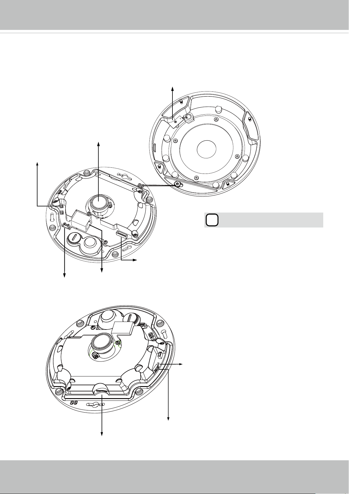
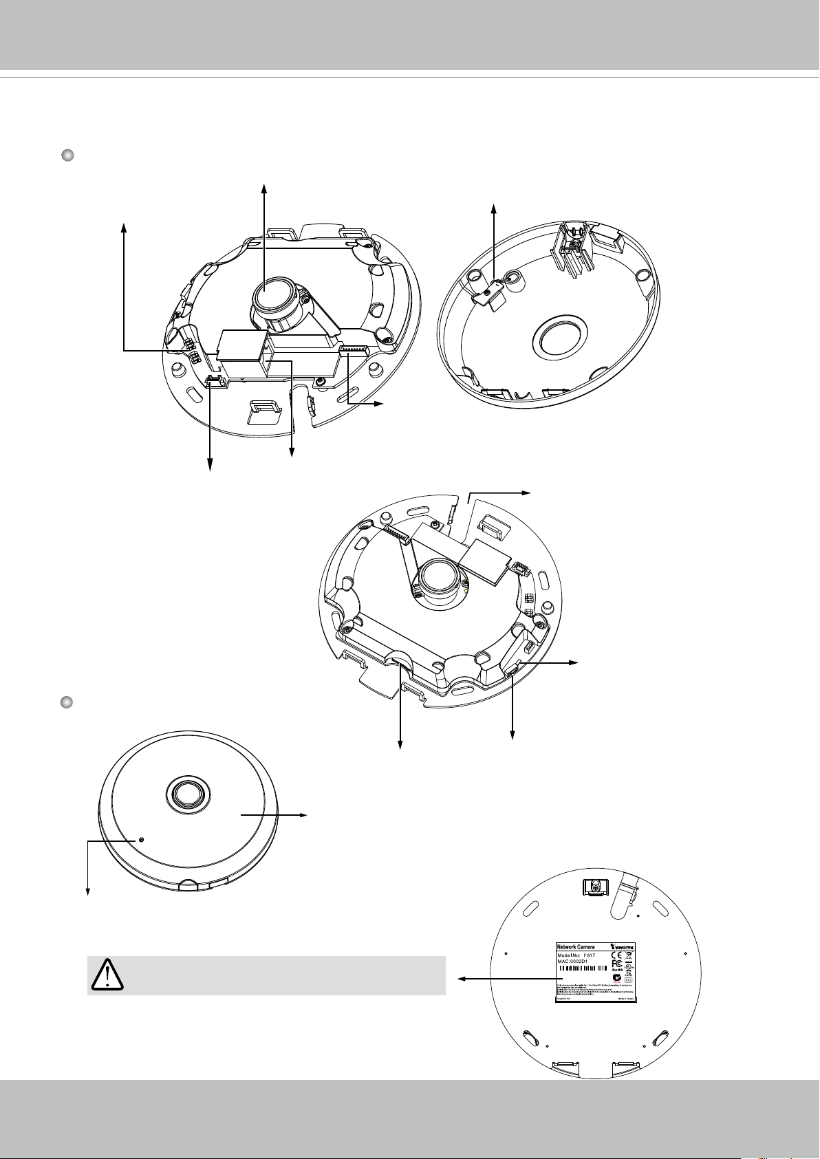
Physical Description - SF8174V
Inner View
Spring Contacts (A)
Lens
Contacts for Internal Microphone (B
Align (B) to (A) when attaching the
dome cover
)
Header (J7)
Header (J6)
Ethernet 10/100 RJ45 Socket
Status LEDs
Reset Button
MicroSD/SDHC/SDXC Card Slot
6 - User's Manual
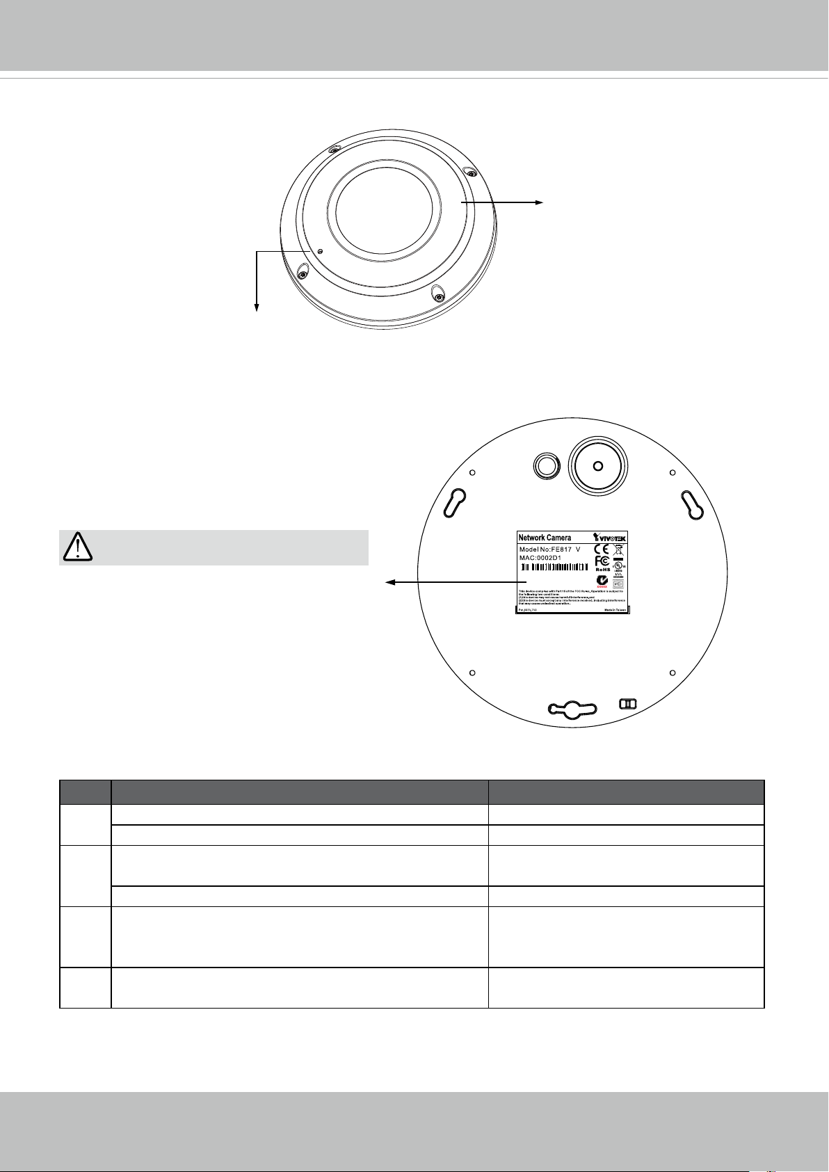
Outer View
Built-in Microphone
VIVOTEK
IP66-rated Vandal-proof
Dome Cover
IMPORTANT:
4
083236
Record the MAC address under the
camera base before installing the camera.
Item LED Status Description
1 Steady Red Power on and system booting
Red LED off Powered off
2 Steady Red + blinking Green every 1 sec. (Green
Network heartbeat
LED on for 1 sec and off for another)
Steady Red + Green LED off Network disconnected
3 Blinking Red every 0.15 sec. + Blinking Green
Upgrading rmware
every 1 sec. (Red LED on for 0.15 sec. and Green
LED on for 1 sec. and off for another)
4 Blinking Red every 0.15 sec. + blinking Green
Restoring defaults
every 0.15 sec
User's Manual - 7
VIVOTEK
Physical Description - SF8174
Inner View
Spring Contacts (A)
Header (J7)
Lens
Contacts for Internal Microphone (B)
Header (J6)
Ethernet 10/100 RJ45 Socket
Cabling Cutout
Outer View
MicroSD/SDHC/SDXC Card Slot
Dome cover
Built-in Microphone
IMPORTANT:
Record the MAC address under the camera base
before installing the camera.
Reset Button
Status LEDs
4
S
083236
8 - User's Manual
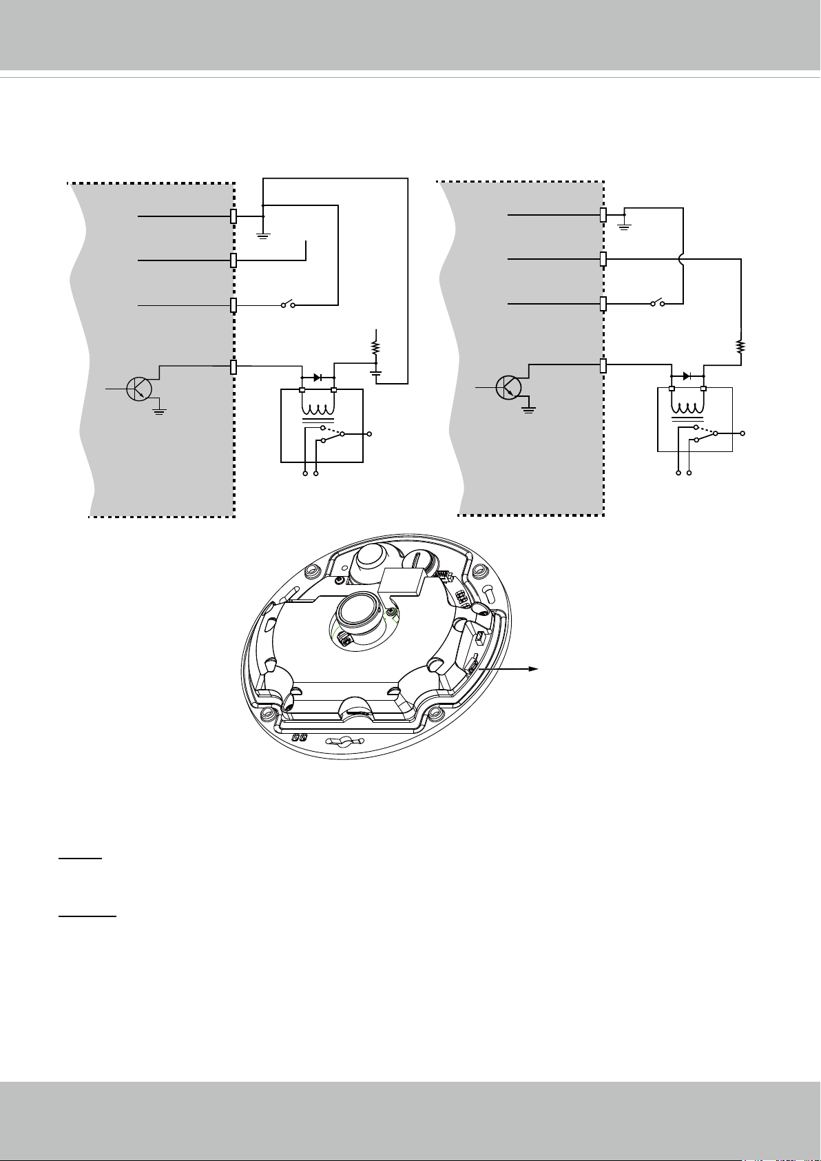
DI/DO Diagram
Please refer to the following illustration for the connection method.
VIVOTEK
Camera Power
BJT transistor
Hardware Reset
GND
Input
Output
VDC
Switch
Relay
+12
VDC
Max.
Camera Power
BJT transistor
GND
Input
Output
VDC
Switch
+12
VDC
Relay
Reset Button
The reset button is used to reset the system or restore the factory default settings. Sometimes
resetting the system can return the camera to normal operation. If the system problems remain
after reset, press the reset button longer to restore the factory settings and install again.
Reset: Press and release the recessed reset button with a straightened paper clip. Wait for the
Network Camera to reboot.
Restore: Press and hold the recessed reset button for at least several seconds to restore. Note
that all settings will be restored to factory defaults.
Micro SD/SDHC/SDXC Card Capacity
This network camera is compliant with Micro SD/SDHC/SDXC 32GB, 64GB, and other
preceding standard SD cards.
User's Manual - 9
VIVOTEK
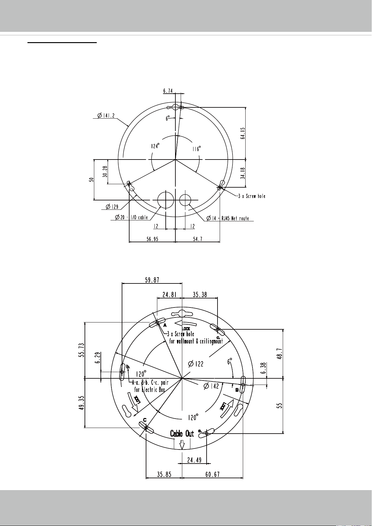
Mounting Positions
Refer to the diagram on the right for the mounting hole positions and the dimensions of the base
plate.
SF8174V
Camera Base Plate Mounting
Positions
Camera Mounting Plate Mounting Positions
10 - User's Manual
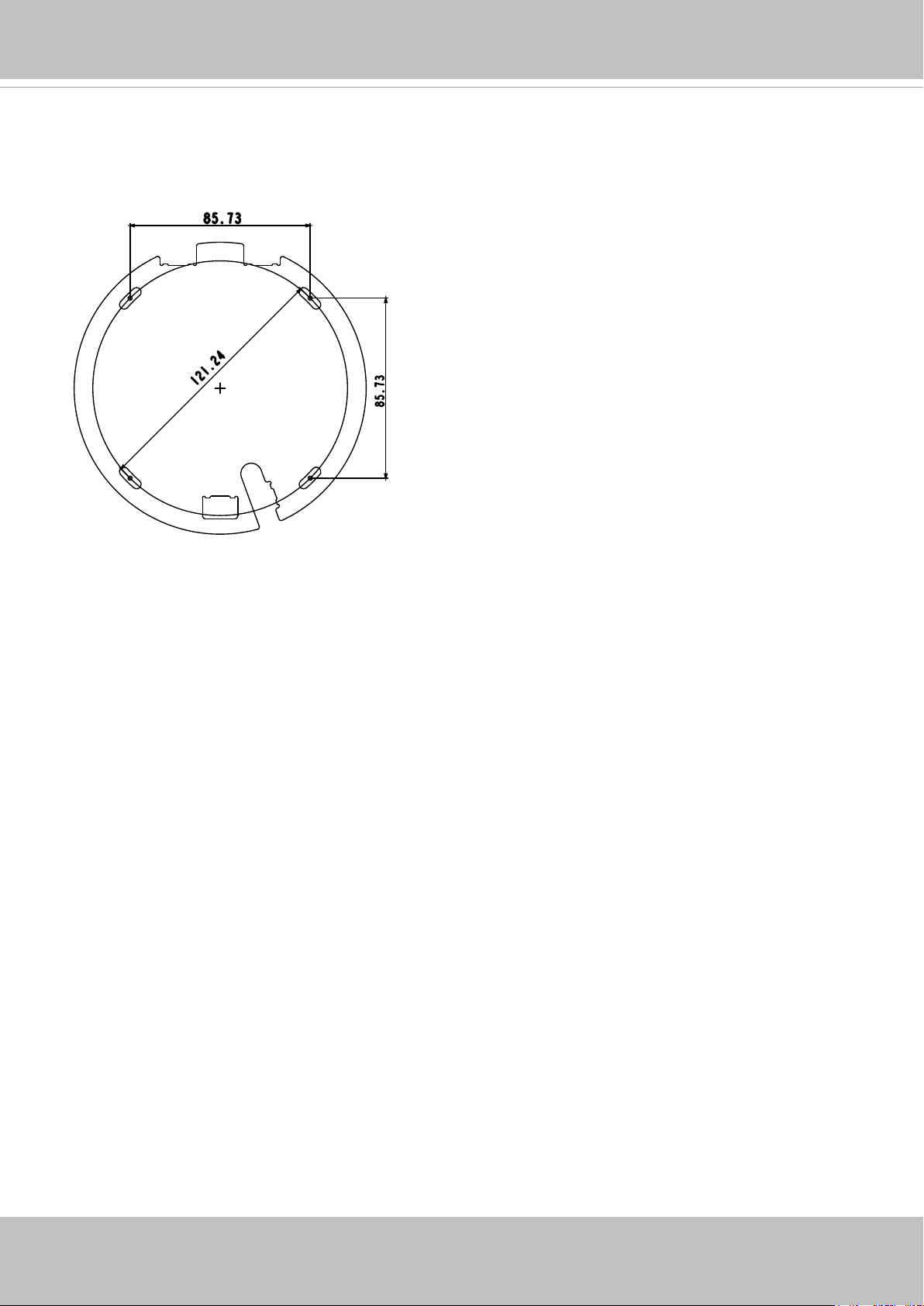
SF8174
VIVOTEK
User's Manual - 11
VIVOTEK
IMPORTANT: for both SF8174V and SF8174:
Refer to the "Panoramic PTZ Installation Guide" in your product CD for design considerations
before you proceed with physical installation.
The camera is intended to be installed with an SD series speed dome camera in a "Panoramic
PTZ" conguration. Users should take the following into account:
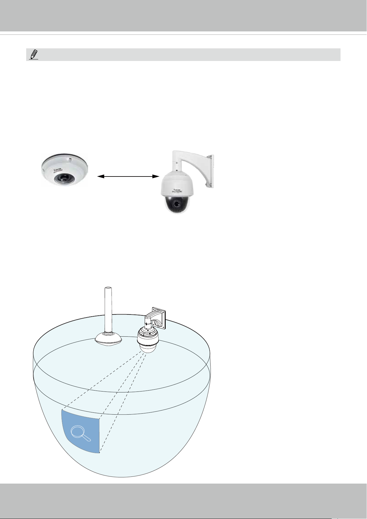
1. There is a dominant - subordinate relationship between the sheye camera and the speed
dome. All congurations are done on a PC running the Calibration tool and a web console
with the sheye camera. The computation required for exerting the Panoramic PTZ control
takes place on the sheye camera.
Controller (dominant)
camera
Auxiliary (subordinate)
camera
2. In a panoramic PTZ conguration, the sheye camera provides an overview over the 360°
hemispheric eld of view; while the speed dome provides tracking, zooming, and keeping an
object in a view of an adequate size. The conguration is operated via the VAST or Milestone
software with easy clicks and drags.
360°
All round view
12 - User's Manual
+
Zoom-in &
tracking
VIVOTEK
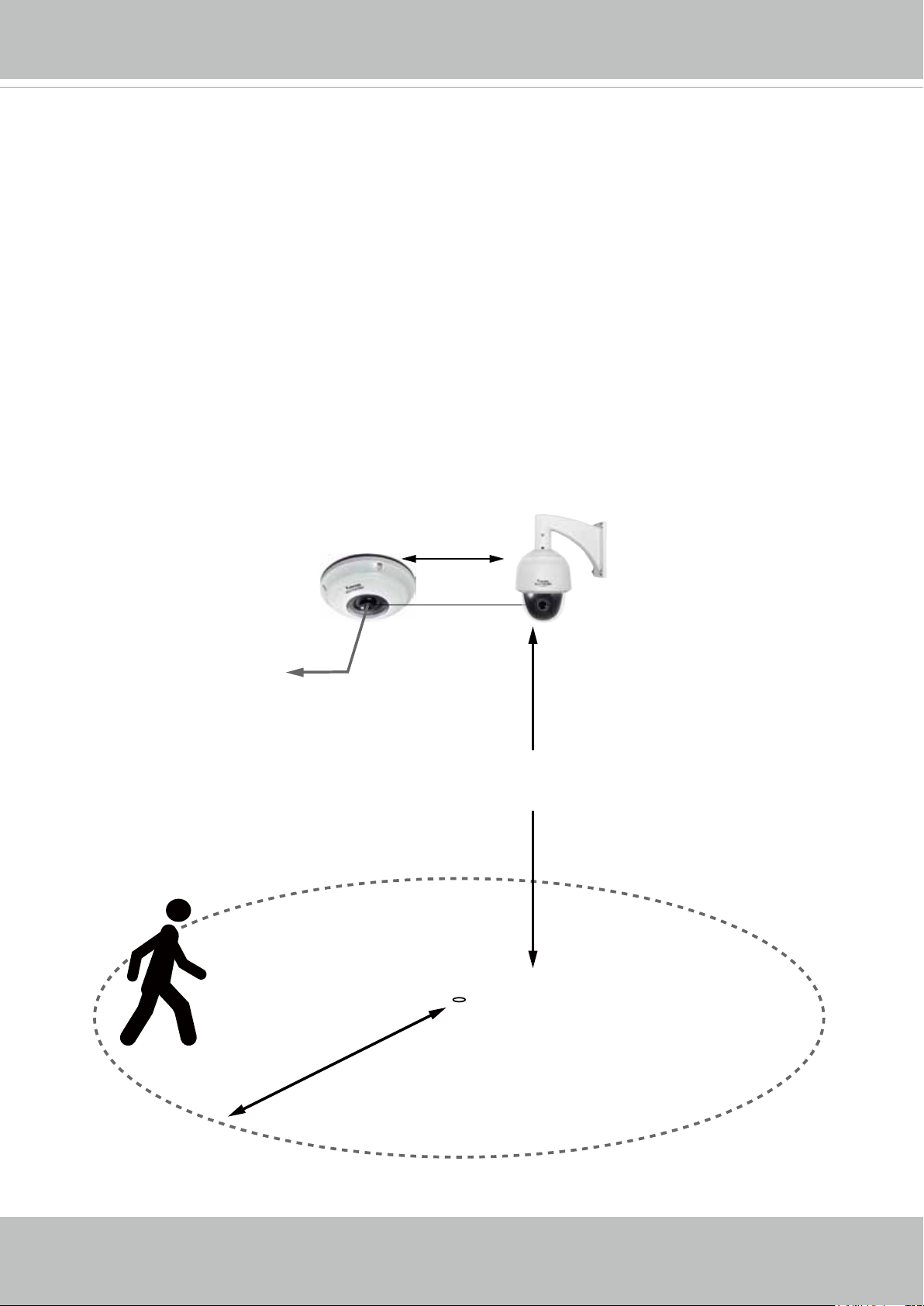
Installation Concerns
Note the following when installing the sheye and speed dome cameras:
1. Mount the cameras closely together, no greater than 1 meter apart.
2. The cameras should be mounted at the height of 3 to 6 meters from the ground, and their
lens at approximately the same height.
3. A conguration thus congured can cover a surveillance area of a radius of 10 meters*.
4. Auto tracking, if applied, is designed to track an intruder in a place where human trafc is
not heavy, such as a warehouse or a load area. Heavy trafc can result in a constant shift of
tracked objects, and reduce the effectiveness of the feature.
* Note that the 10 meter radius only applies when using the Auto tracking feature. If using
manual control, the surveillance area can be much larger.
Controller (dominant)
camera
Lens at
approx. the same height
Auxiliary (subordinate)
camera
< 1 meter
3 ~ 6 meters
10 meters radius
User's Manual - 13
VIVOTEK
Hardware Installation - SF8174V
Please refer to page 20 for the installation details of the SF8174.
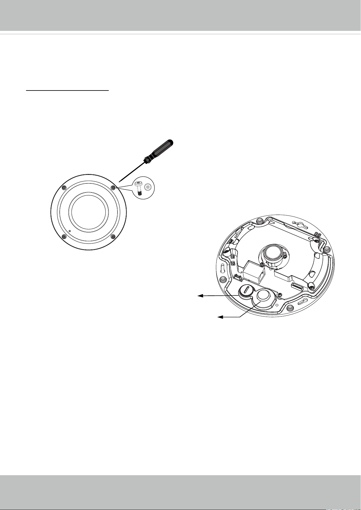
Opening Dome Cover
First, use the supplied screwdriver to loosen the four screws and detach the dome cover from
the camera base. Then, follow the steps below to install the camera to either a ceiling or a wall.
Tamper-proof Screw
Remove the stoppers and route cables through
the openings.
Rubber Stopper on the hole
for Power & IO Cables
Rubber Seal Plug on the
hole for RJ45 Ethernet
Cable
14 - User's Manual
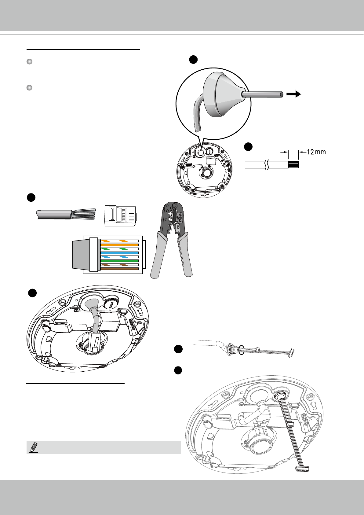
Connecting RJ45 Ethernet Cable
VIVOTEK
RJ45 Cable Dimension (unit: mm)
Recommended cable gauge: 5 to 8mm
Assembly Steps
1. Drill a hole on the rubber seal plug and
insert an Ethernet cable through the
opening.
2. Strip part of the sheath from the Ethernet
cable.
3
o: white/orange stripe
O: orange solid
g: white/green stripe
B: blue solid
b: white/blue stripe
G: green solid
br: white/brown stripe
BR: brown solid
O
G
br
BR
o
g
B
b
1
2
3
4
5
6
7
8
1
Rubber Seal Plug
2
3. You will need an RJ45 crimping tool to
attach the Ethernet wires to a connec-
tor. When done, connect the cable to
the camera’s Ethernet RJ45 socket.
4
4. Feed the Ethernet cable from the bottom of the
camera and through the hole. Attach the rubber
seal plug for water proong.
1
2
Connecting DC Power Cable
1. Add the supplied rubber washer to the cable
as shown in the picture.
2. Feed the cable from the bottom of the camera and tighten the plastic base for water-
proong.
NOTE:
Connect the supplied power & IO cables if your
switch does not support PoE.
User's Manual - 15
VIVOTEK
47mm
IMPORTANT:
Refer to the "Panoramic PTZ Installation Guide" in your product CD for design considerations
before you proceed with physical installation.
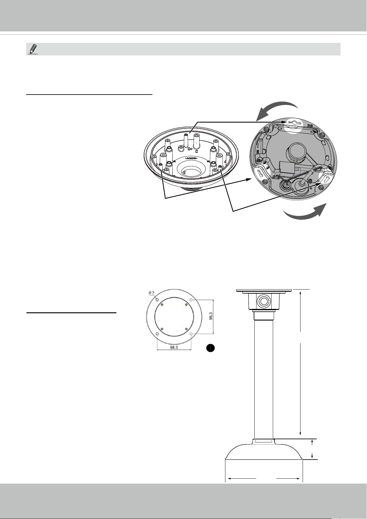
Attach Camera to Mounting Adapter
To attach the camera to AM-51A
mounting adaptor,
Hole marked as D+
1. Remove the camera's top cover.
2. Fasten 2 included screws to the
D holes (not the D+ hole).
3. Route cables through the
adapter.
4. Align the camera with the
mounting adapter and let the
2 screws enter the key holes
located on the sides where the
camera's cabling interfaces
D
D
reside, e.g., the Ethernet port.
5. Rotate the camera counterclockwise. You can then see
the D+ hole through the slotted
screw hole (in front of the Micro
SD slot).
6. Fasten screws to secure the
camera to the mounting adapter.
Ceiling Mount Installation
Install the Pendant Pipe
Below is a sample procedure
using a pendant pipe:
1. Determine a hard surface ceil-
ing location, and use the four
mounting holes on the pendant
head to mark the positions
where holes will be drilled to
secure the pendant head. Note
that screws are user-supplied
and they should be at least
11mm long.
2. Route cables through the pendant pipe and the pendant
head.
16 - User's Manual
AM-114
473 mm
1
AM-117
AM-51A
178 mm
VIVOTEK
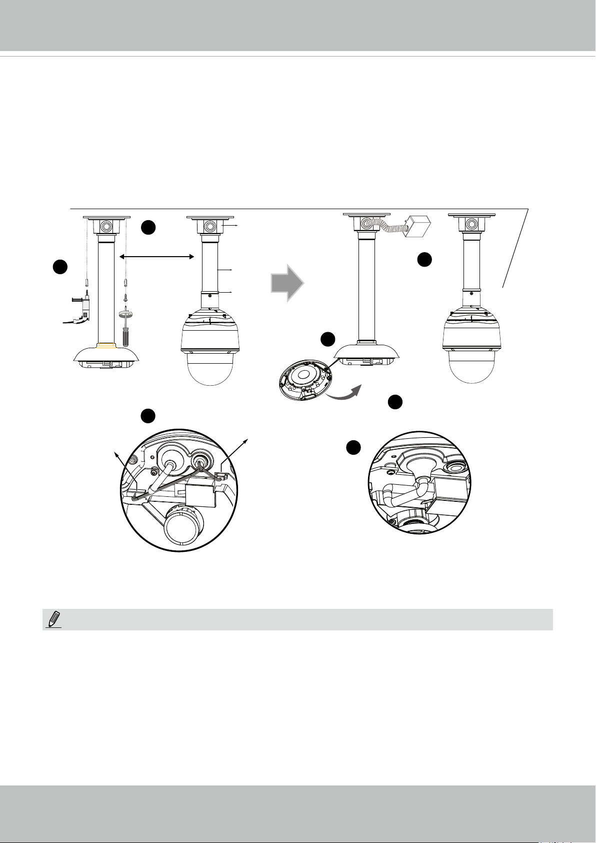
Install to the Ceiling
1. Drill pilot holes into the ceiling. Then hammer four anchors into the holes.
2. Secure the pendant head to the ceiling using four screws.
3. Connect the two white header connectors to the J6 and J7 connectors.
4. Connect the Ethernet cable to the RJ-45 socket.
5. You will nd a desiccant bag attached to the camera. Replace the desiccant bag included in
the camera with the one shipped within the accessory bag.
6. Attach the dome cover to the camera by driving its anti-tamper screws.
7. Route cables through a 3/4” conduit from the pendant head.
1
Header (J6)
2
30~100cm
3
AM-114
7
AM-116
AM-519
5
6
Header (J7)
4
NOTE:
Arrange the cables neatly to avoid getting in the way when the dome cover is attached.
User's Manual - 17

VIVOTEK
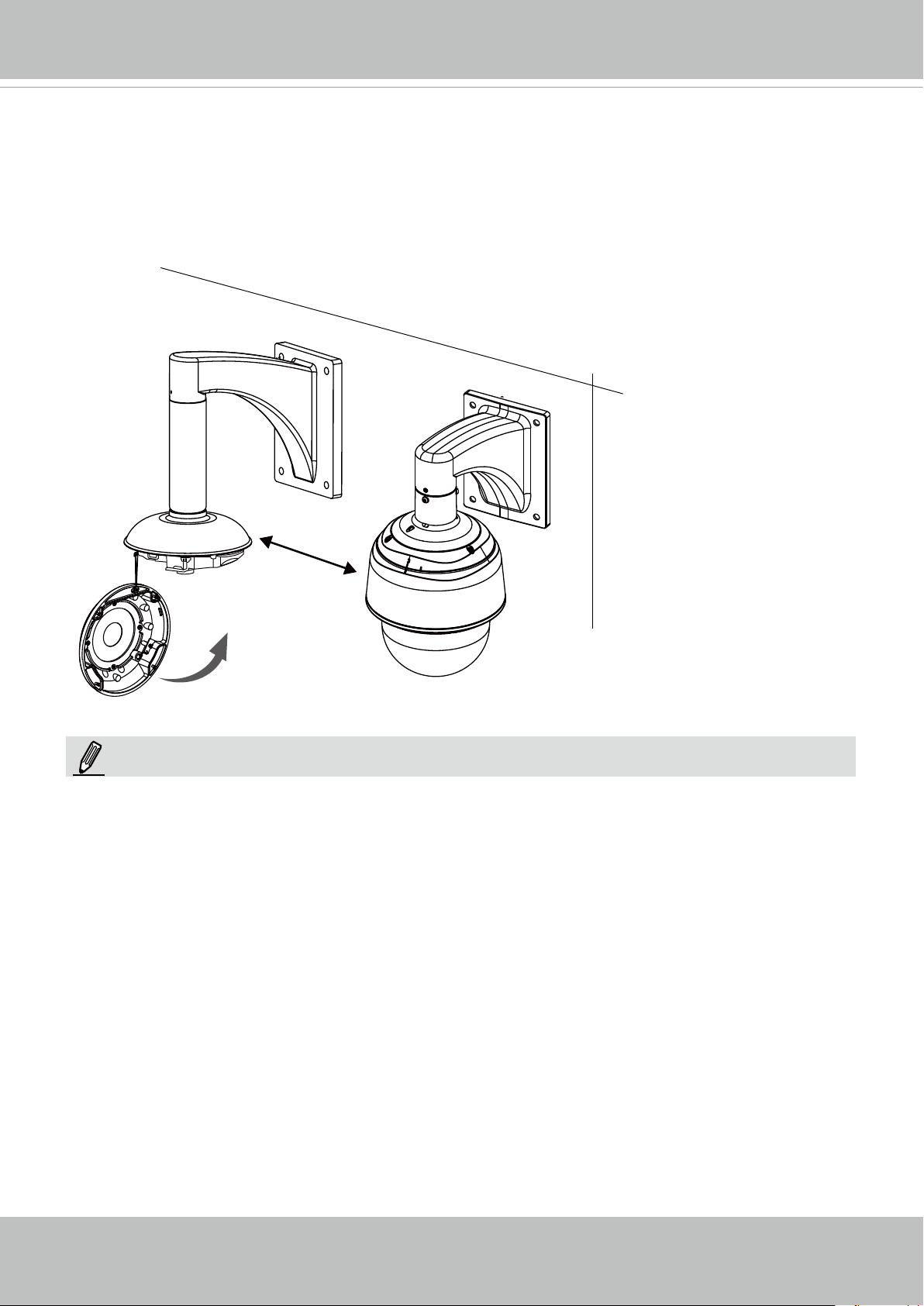
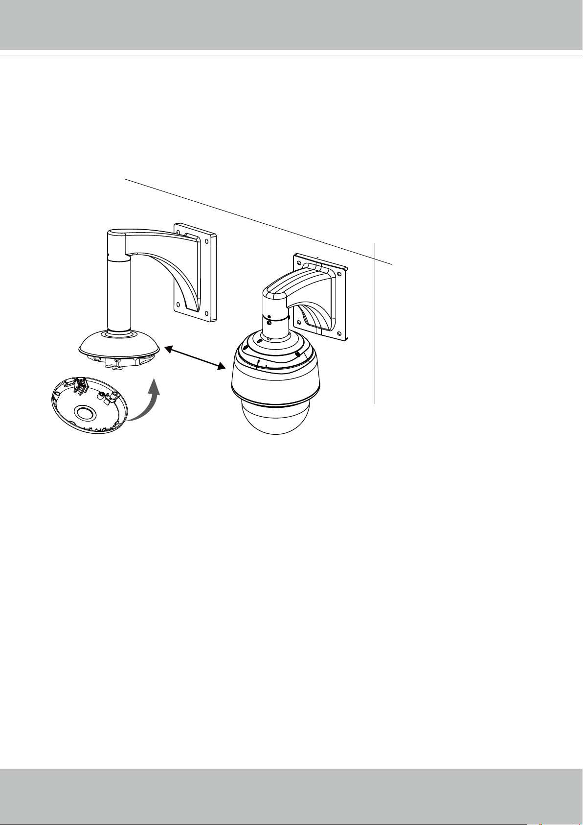
Wall Mount Bracket Installation
Below is a sample procedure using a wall mount bracket and a pendant pipe:
1. Determine a hard surface ceiling location. Use the four mounting holes on the wall mount
bracket to mark the positions where holes will be drilled to secure the bracket and routing
cables. Note that screws are user-supplied and they should be at least 11mm long.
2. Feed cables through the bracket.
3. Install the pendant pipe.
4. Install the camera to the mounting adapter. See Attach Camera to Mounting Adapter on the
previous page.
5. Install the mounting adapter to pendant pipe.
6. Tighten the connection using the included hex wrench.
1
6
AM-51A
4
2
3
AM-116
AM-212
5
18 - User's Manual
VIVOTEK
7. Install the speed dome camera next to the sheye, with their lens positioned at approximately
the same height. For details about speed dome installation, please refer to its documentation.
8. Connect all cabling, including the IO cables to J6 and J7, and the Ethernet cable to RJ-45
connector.
9. Install the dome cover by fasteninng the anti-tamper screws.
30~100cm
NOTE:
If DC power is preferred, it should comply with: O/P: 12VDC, 1.5Amin., L.P.S. per IEC 60950-1.
User's Manual - 19
VIVOTEK
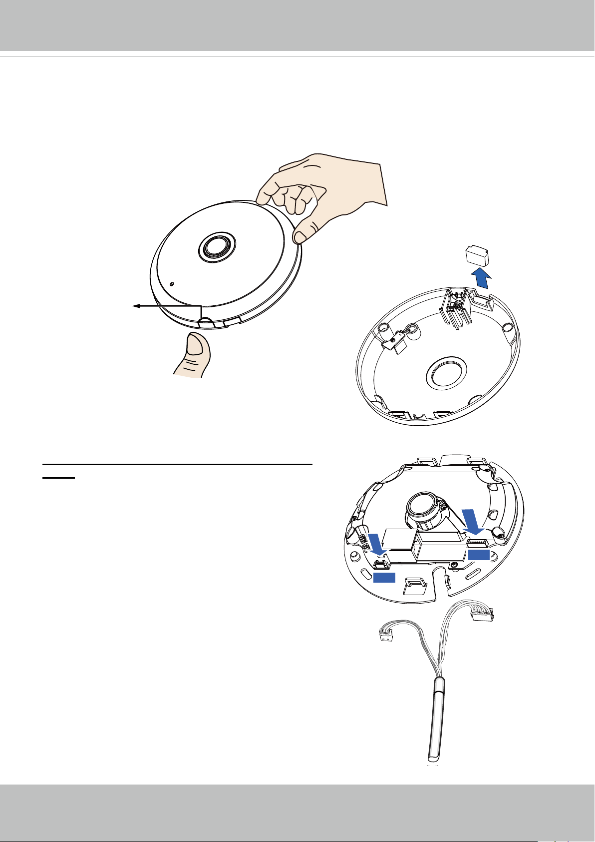
Hardware Installation - SF8174
First, open the dome cover by pressing the release button. You may squeeze the opposite edge
of the dome cover if the dome cover does not come off easily. Then, follow the steps below to in-
stall the camera to either a ceiling or a wall.
Slide cover
Release button
If you plan to route cables from the side of camera,
remove the rubber slide cover from the dome cover.
Connecting Ethernet Cable & the Power and IO
Cable
Connect the supplied power & IO cables if your
switch does not support PoE. Connect the white
header connectors to J6 and J7 on the camera.
Power & IO Cable
J6
J7
20 - User's Manual
VIVOTEK
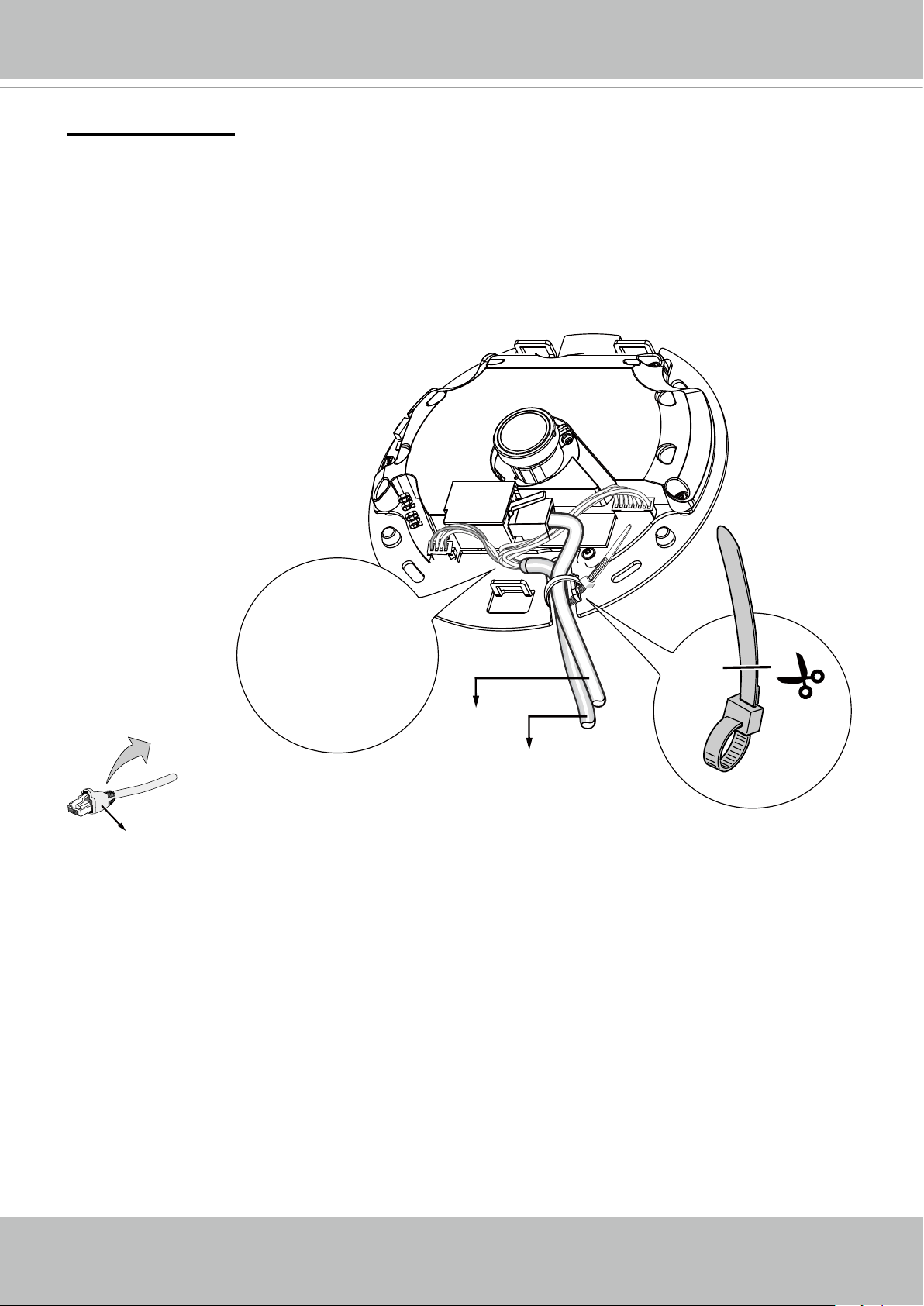
Connecting Cables
If you need to route cables through the side opening, proceed with the following:
1. Connect the Ethernet and the Power & IO cables. The Ethernet cable
is user-supplied.
2. Use an included cable tie to secure the Ethernet and IO cable to the base plate. Insert the
cable tie through the vertical mounting tab located on the edge of the cabling cutout.
3. Make a clearance between cables and the vertical mounting tab. Arrange the cables neatly to
avoid getting in the way when the dome cover is attached.
4. Cut the extra length from the cable tie.
If you route cables through a drill hole
on a wall/ceiling, simply route cables
through the cabling cutout.
Strain relief boot
Make a clearance
between cables and
the vertical tab
Ethernet
Power and IO cables
It is recommended to remove the strain relief boot if your Ethernet cable
comes with one.
User's Manual - 21
VIVOTEK
47mm
IMPORTANT:
Refer to the "Panoramic PTZ Installation Guide" in your product CD for design considerations
before you proceed with physical installation.
Attach Camera to Mounting Adaptor
An adapter bracket, AM-517, is required.
1. Align the bracket's screw slots with mounting holes on the AM-51A.
2. Secure the bracket to AM-51A using 2 pan head M2.6 screws.
B
”
4
”
6
1
1
/
1
A
”
1
16
1
/
4
B
4
B
1
4
1
/
1
6
”
A
”
A -
4
Cable out
3. Align the camera's screw slots
with the C holes.
4. Use the included M2.6 screws
to secure camera to bracket.
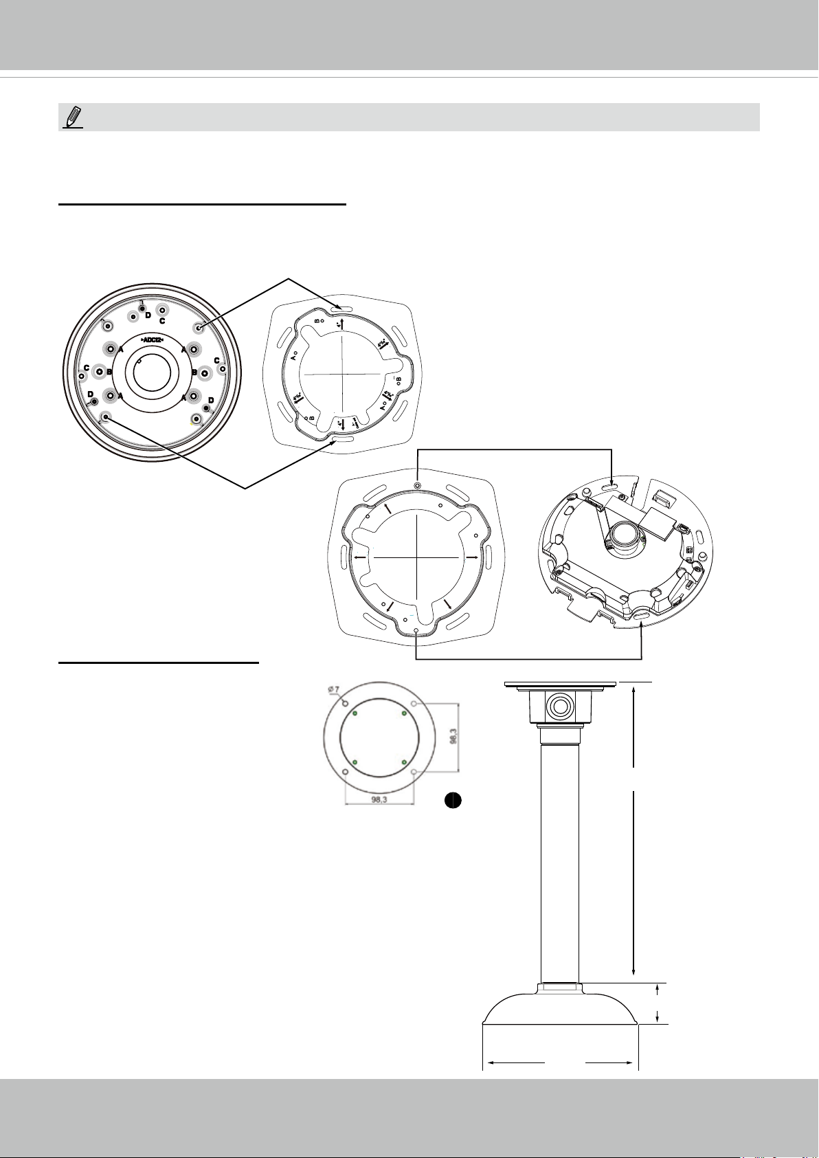
Ceiling Mount Installation
Install the Pendant Pipe
Below is a sample procedure
using a pendant pipe:
1. Determine a hard surface ceil-
ing location, and use the four
mounting holes on the pendant
head to mark the positions
where holes will be drilled to
secure the pendant head. Note
that screws are user-supplied
and they should be at least
11mm long.
Cable out
C
4
11
/
16
B
4 ”
A -
A
”
A
”
B
4 ”
4
11
/
4
11
/
16
16
”
B
C
AM-114
473 mm
1
AM-117
2. Route cables through the pendant pipe and the pendant
head.
22 - User's Manual
AM-51A
178 mm
VIVOTEK
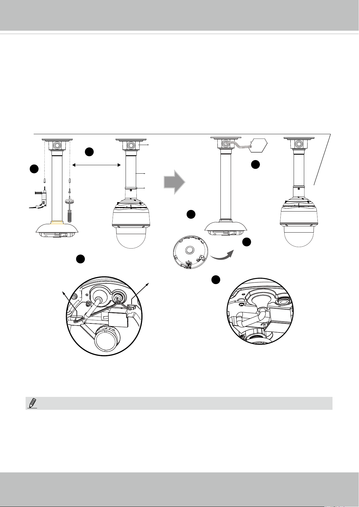
Install to the Ceiling
1. Drill pilot holes into the ceiling. Then hammer four anchors into the holes.
2. Secure the pendant head to the ceiling using four screws.
3. Connect the two white header connectors to the J6 and J7 connectors.
4. Connect the Ethernet cable to the RJ-45 socket.
5. You will nd a desiccant bag attached to the camera. Replace the desiccant bag included in
the camera with the one shipped within the accessory bag.
6. Attach the dome cover to the camera.
7. Route cables through a 3/4” conduit from the pendant head.
AM-114
2
1
Header (J6)
30~100cm
3
AM-116
AM-519
Header (J7)
7
5
6
4
NOTE:
Arrange the cables neatly to avoid getting in the way when the dome cover is attached.
User's Manual - 23
VIVOTEK
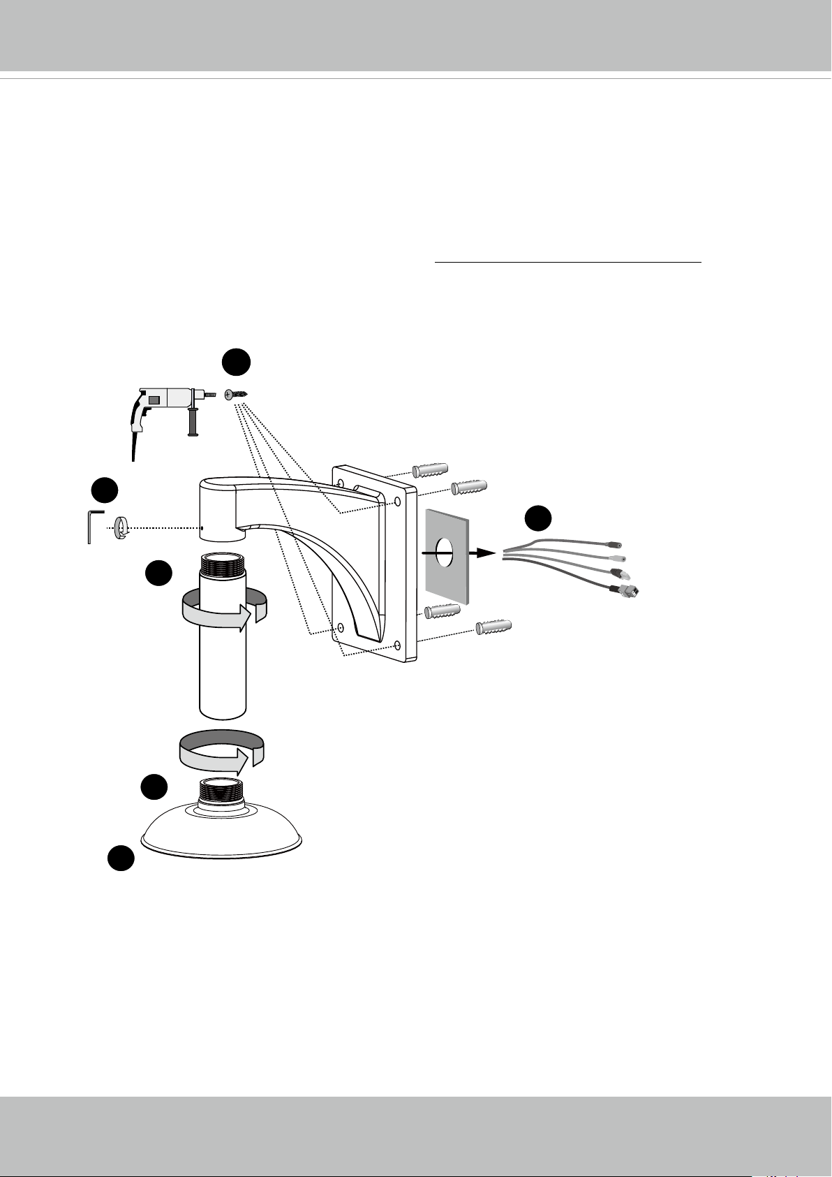
Wall Mount Bracket Installation
Below is a sample procedure using a wall mount bracket and a pendant pipe:
1. Determine a hard surface ceiling location. Use the four mounting holes on the wall mount
bracket to mark the positions where holes will be drilled to secure the bracket and routing
cables. Note that screws are user-supplied and they should be at least 11mm long.
2. Feed cables through the bracket.
3. Install the pendant pipe.
4. Install the camera to the mounting adapter. See Attach Camera to Mounting Adapter on the
previous page.
5. Install the mounting adapter to pendant pipe.
6. Tighten the connection using the included hex wrench.
1
6
AM-51A
4
2
3
AM-116
AM-212
5
24 - User's Manual
VIVOTEK
7. Install the speed dome camera next to the sheye, with their lens positioned at approximately
the same height. For details about speed dome installation, please refer to its documentation.
8. Connect all cabling, including the IO cables to J6 and J7, and the Ethernet cable to RJ-45
connector.
9. Install the dome cover.
30~100cm
User's Manual - 25
VIVOTEK
Network Deployment
Setting up the Network Camera over the Internet
There are several ways to set up the Network Camera over the Internet. The rst way is to set
up the Network Camera behind a router. The second way is to utilize a static IP. The third way is
to use PPPoE.
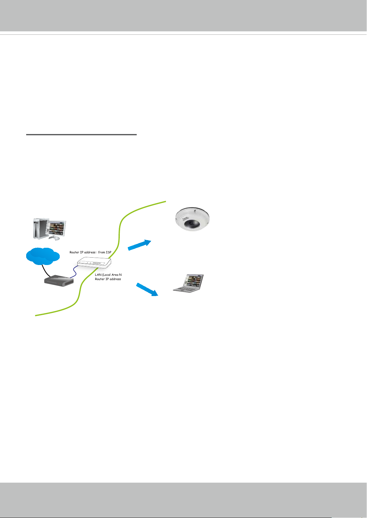
Internet connection via a router
Before enabling the access to the Network Camera over the Internet, make sure you have a
router and follow the steps below.
1. Connect your Network Camera behind a router, the Internet environment is illustrated below.
Regarding how to obtain your IP address, please refer to Software Installation on page 30 for
details.
IP address : 192.168.0.3
Subnet mask : 255.255.255.0
Default router : 192.168.0.1
IP address : 192.168.0.2
Subnet mask : 255.255.255.0
Default router : 192.168.0.1
Internet
Cable or DSL Modem
WAN (Wide Area Network )
Router IP address : from ISP
LINK
POWER
COLLISION
RECEIVE
1
2
PARTITION
3
4
5
LAN (Local Area Network)
Router IP address : 192.168.0.1
2. In this case, if the Local Area Network (LAN) IP address of your Network Camera is
192.168.0.3, please forward the following ports for the Network Camera on the router.
■ Secondary HTTP port: 8080
■ RTSP port: 554
■ RTP port for audio: 5558
■ RTCP port for audio: 5559
■ RTP port for video: 5556
■ RTCP port for video: 5557
If you have changed the port numbers on the Network page, please open the ports
accordingly on your router. For information on how to forward ports on the router, please refer
to your router’s user’s manual.
3. Find out the public IP address of your router provided by your ISP (Internet Service Provider).
Use the public IP and the secondary HTTP port to access the Network Camera from the
Internet. Please refer to Network Type on page 78 for details.
26 - User's Manual
VIVOTEK
For example, your router and IP settings may look like this:
Device IP Address: internal
port
IP Address: External Port (Mapped port on the
router)
Public IP of router 122.146.57.120
LAN IP of router 192.168.2.1
Camera 1 192.168.2.10:80 122.146.57.120:8000
Camera 2 192.168.2.11:80 122.146.57.120:8001
... ... ...
Congure the router, virtual server or rewall, so that the router can forward any data coming
into a precongured port number to a network camera on the private network, and allow data
from the camera to be transmitted to the outside of the network over the same path.
From Forward to
122.146.57.120:8000 192.168.2.10:80
122.146.57.120:8001 192.168.2.11:80
... ...
When properly congured, you can access a camera behind the router using the HTTP request
as follows: http://122.146.57.120:8000
If you change the port numbers on the Network conguration page, please open the ports accordingly on your router. For example, you can open a management session with your router to
congure access through the router to the camera within your local network. Please consult your
network administrator for router conguration if you have troubles with the conguration.
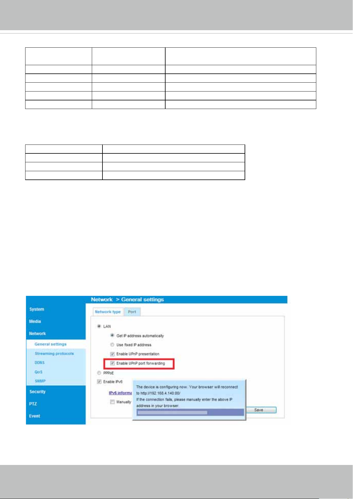
For more information with network conguration options (such as that of streaming ports),
please refer to Conguration > Network Settings. VIVOTEK also provides the automatic port for-
warding feature as an NAT traversal function with the precondition that your router must support
the UPnP port forwarding feature.
User's Manual - 27
VIVOTEK
Internet connection with static IP
Choose this connection type if you are required to use a static IP for the Network Camera.
Please refer to LAN conguration on page 78 for details.
Internet connection via PPPoE (Point-to-Point over Ethernet)
Choose this connection type if you are connected to the Internet via a DSL Line. Please refer to
PPPoE on page 99 for details.
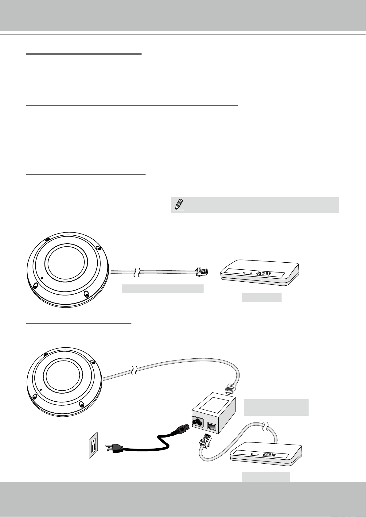
Set up the Network Camera through Power over Ethernet (PoE)
When using a PoE-enabled switch
The Network Camera is PoE-compliant, allowing transmission of power and data via a single
Ethernet cable. Follow the below illustration to connect the Network Camera to a PoE-enabled
switch via an Ethernet cable.
NOTE:
1. The camera is only to be connected to PoE networks
without routing to outside plants.
2. For PoE connection, use only UL listed I.T.E. with
PoE output.
L
I
N
POW
ER
C
O
LL
I
S
ION
1
K
RECEIVE
PARTITIO
2
3
N
4
5
Power + Data Transmission
PoE Switch
When using a non-PoE switch
If your switch/router does not support PoE, use a PoE power injector (optional) to connect
between the Network Camera and a non-PoE switch.
28 - User's Manual
PoE Power Injector
(optional)
L
I
N
POW
ER
C
O
LL
I
S
ION
1
K
RECEIVE
PARTITIO
2
3
N
4
5
Non-PoE Switch
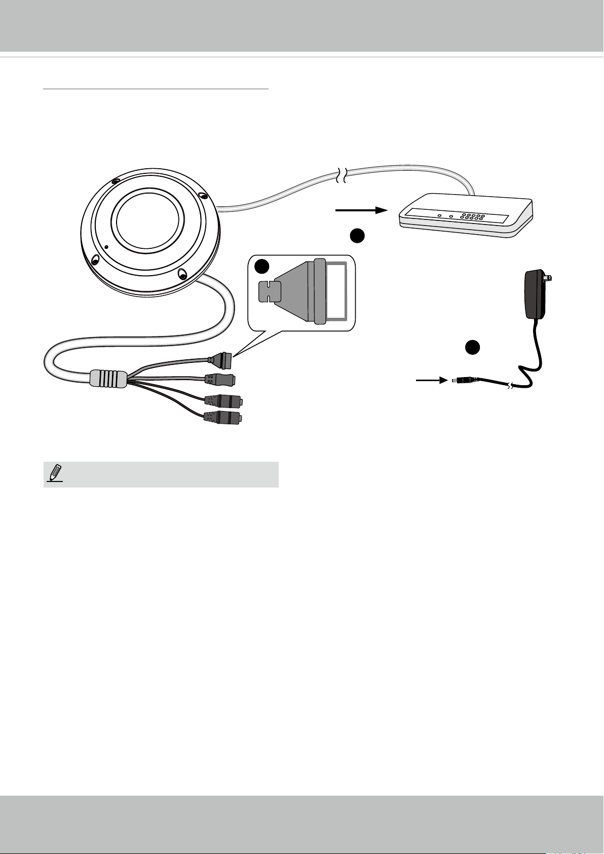
General Connection (without PoE)
1. If you have external DI devices, make the connection from general I/O terminal block.
2. Ethernet, power and IO cables are user-supplied.
3. Connect DC power cord to a DC Adapter, and then to a power outlet.
L
I
N
POW
ER
C
O
LL
I
S
ION
1
2
1
K
RECEIVE
PARTITIO
3
N
4
5
VIVOTEK
3
General I/O Terminal Block
Power Cord Socket (Black)
Microphone In (Pink)
Audio Out (Green)
NOTE:
The power adapter should comply with L.P.S.
regulations featuring O/P: 12V DC, 1.5A min.
+3V3
DO
D1
GND
+3V3 : Power, 3.3V DC
DO : Digital Output
DI : Digital Input
GND : Ground
2
User's Manual - 29
VIVOTEK
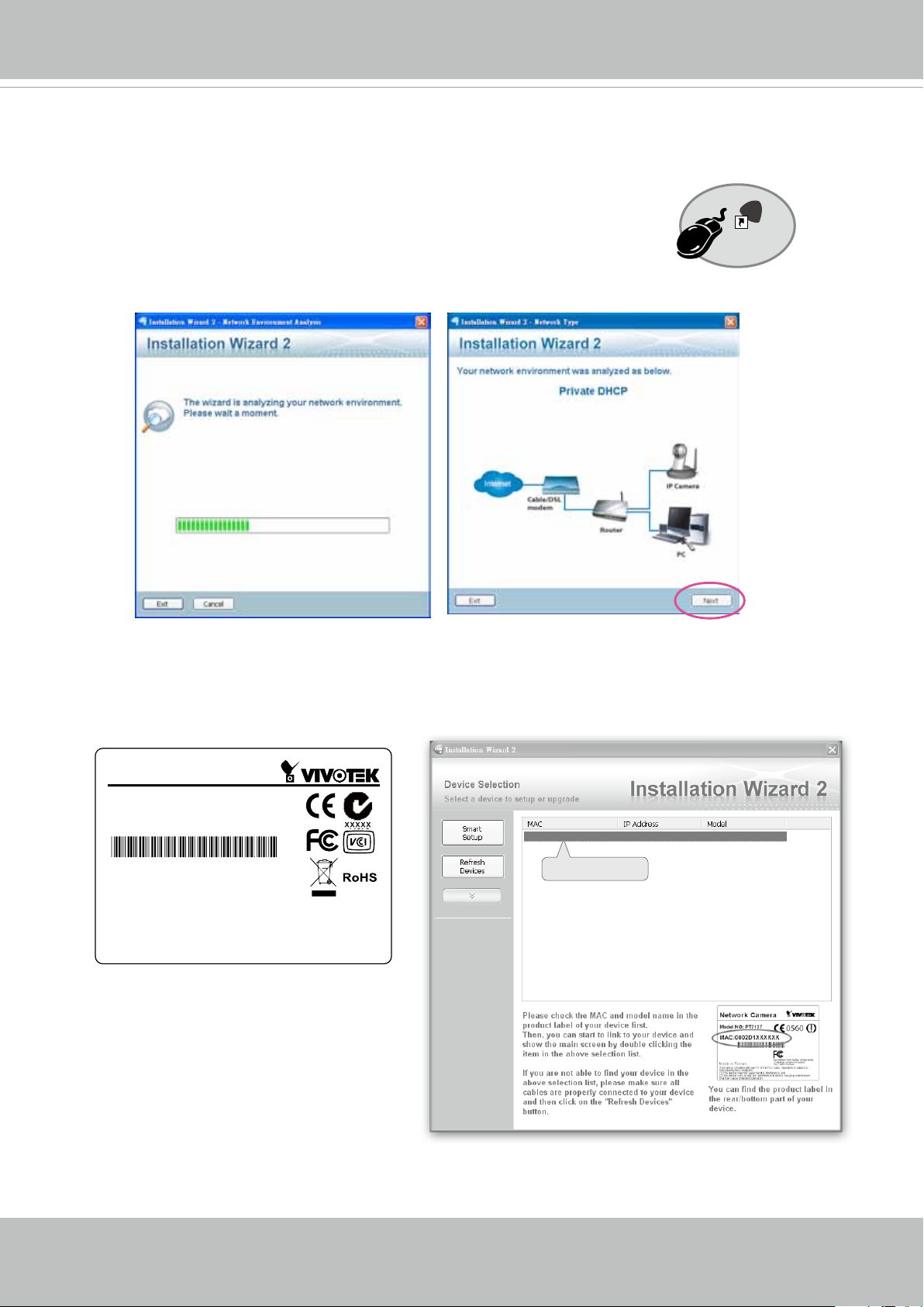
Software Installation
Installation Wizard 2 (IW2), free-bundled software included on the product CD, helps you set up
your Network Camera on the LAN.
IW
1. Install IW2 under the Software Utility directory from the software CD.
Double click the IW2 shortcut on your desktop to launch the program.
2. The program will conduct an analysis of your network environment.
After your network environment is analyzed, please click Next to continue the program.
2
Installation
Wizard 2
3. The program will search for all VIVOTEK network devices on the same LAN.
4. After a brief search, the main installer window will pop up. Double-click on the MAC address
that matches the one printed on the camera label or the S/N number on the package box label
to open a browser management session with the Network Camera.
Network Camera
Model No: SF8174V
MAC: 0002D1083236
This device complies with part 15 of the FCC Rules. Operation is subject to
the following two conditions:
(1) this device may not cause harmful interference, and
(2) this device must accept any interference received, including interference
that may cause undesired operation.
Pat. 6,930,709
Made in Taiwan
00-02-D1-08-32-36 192.168.5.109 SF8174V
0002D1083236
30 - User's Manual
 Loading...