

Vivotek SF8174 Installation
Warning Before Installation
English
Power off the Network Camera as
soon as smoke or unusual odors
Refer to your user’s manual for the
operating temperature.
are detected.
Do not place the Network Camera
on unsteady surfaces.
Do not insert sharp or tiny objects
Do not touch the Network Camera
during a lightning storm.
Do not drop the Network Camera.
into the Network Camera.
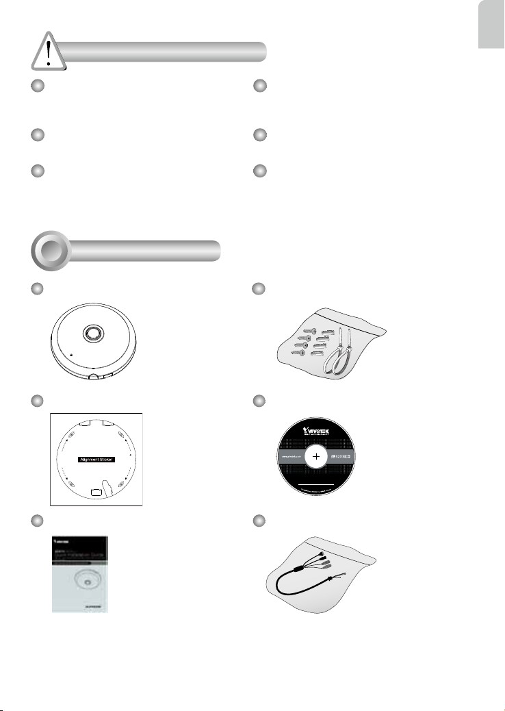
Package Contents
1
SF8174
Screws / Anchors / Cable tie
Alignment Stickers Software CD
D
r
i
l
l
h
o
l
e
e
l
o
h
l
l
i
r
D
5
1
0
G
0
0
1
0
2
0
Quick Installation Guide
Power & I/O Cables
EN - 1
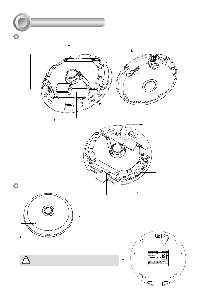
Physical Description
2
Inner View
Spring Contacts (A)
Header (J7)
Outer View
Lens
Contacts for Internal Microphone (B)
Header (J6)
Ethernet 10/100 RJ45 Socket
Cabling Cutout
Status LEDs
Reset Button
MicroSD/SDHC/SDXC Card Slot
Dome cover
Built-in Microphone
IMPORTANT:
Record the MAC address under the camera base
before installing the camera.
EN - 2
4
S
083236
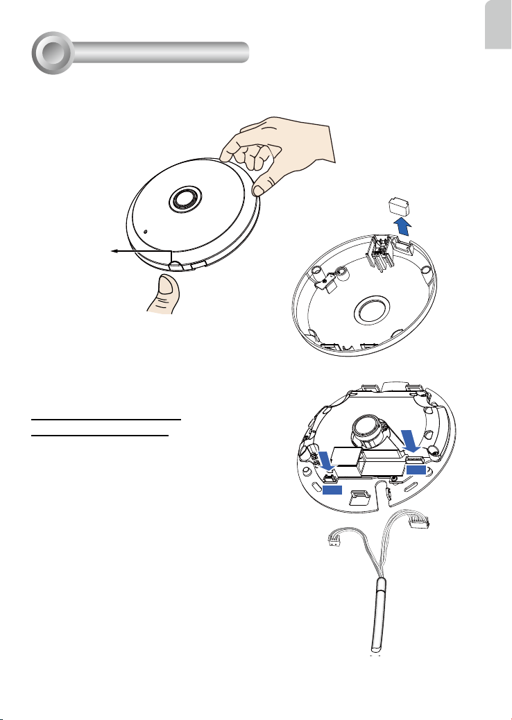
Hardware Installation
3
First, open the dome cover by pressing the release button. You may squeeze the opposite edge of
the dome cover if the dome cover does not come off easily. Then, follow the steps below to install the
camera to either a ceiling or a wall.
Slide cover
Release button
If you plan to route cables from the side of camera,
remove the rubber slide cover from the dome cover.
Connecting Ethernet Cable
& the Power and IO Cable
English
Connect the supplied power & IO cables if your switch
does not support PoE. Connect the white header
connectors to J6 and J7 on the camera.
EN - 3
J6
J7
Power & IO Cable
 Loading...