

Page 1
Page 2

VIVOTEK - A Leading Provider of Multimedia Communication Solutions
2 - User's Manual
Table of Contents
Overview.......................................................................................................................................................3
Read before use ��������������������������������������������������������������������������������������������������������������������������������������3
Package contents ������������������������������������������������������������������������������������������������������������������������������������3
Physical description ���������������������������������������������������������������������������������������������������������������������������������4
Installation ....................................................................................................................................................7
Hardware installation �������������������������������������������������������������������������������������������������������������������������������7
Network deployment ��������������������������������������������������������������������������������������������������������������������������������8
Home Page.................................................................................................................................................16
Conguration ..............................................................................................................................................18
Device ���������������������������������������������������������������������������������������������������������������������������������������������������18
Network �������������������������������������������������������������������������������������������������������������������������������������������������20
LAN �������������������������������������������������������������������������������������������������������������������������������������������������������20
Access list ���������������������������������������������������������������������������������������������������������������������������������������������21
DDNS ����������������������������������������������������������������������������������������������������������������������������������������������������22
Security �������������������������������������������������������������������������������������������������������������������������������������������������24
Schedule �����������������������������������������������������������������������������������������������������������������������������������������������26
Recording Policy �����������������������������������������������������������������������������������������������������������������������������������28
Trigger ��������������������������������������������������������������������������������������������������������������������������������������������������� 31
System ��������������������������������������������������������������������������������������������������������������������������������������������������34
Maintenance ������������������������������������������������������������������������������������������������������������������������������������������36
Backup ��������������������������������������������������������������������������������������������������������������������������������������������������37
System log ���������������������������������������������������������������������������������������������������������������������������������������������38
Monitor........................................................................................................................................................39
User Interface of Monitor Page �������������������������������������������������������������������������������������������������������������39
Functions of Monitor Page ��������������������������������������������������������������������������������������������������������������������41
History ........................................................................................................................................................44
User Interface of History Page ��������������������������������������������������������������������������������������������������������������44
Functions of History Page ���������������������������������������������������������������������������������������������������������������������45
Appendix.....................................................................................................................................................50
Technical Specications ������������������������������������������������������������������������������������������������������������������������50
Page 3

VIVOTEK - A Leading Provider of Multimedia Communication Solutions
User's Manual - 3
Overview
VIVOTEK NR7401 network video recorder provides an easy recording solution for VIVOTEK
network cameras and allows users to perform real-time monitoring and recording at the same time�
Supporting recording for up to 9 channels in both MPEG-4 and MJPEG formats, NR7401 provides
several recording options, including alarm recording, scheduled recording, and manual recording�
Installation is made easy because NR7401 can automatically detect and install VIVOTEK cameras
without any configuration� Furthermore, NR7401 has four 802�3af compliant PoE (Power over
Ethernet) ports that reduce cabling problems� NR7401 offers a user-friendly interface where users
can congure network settings as well as control camera movement. By installing a large-volume
SATA hard disk (up to 1TB) in NR7401, users can record high-denition video streams from mega-
pixel cameras for a long period without worrying about running out of storage capacity� NR7401
comes with a built-in gateway that separates network cameras from regular data network so the
inuence of video recording on bandwidth is minimized. NR7401 also has four digital input and one
digital out interfaces to allow for connection with external sensors and alarms� In addition, NR7401
offers an USB port, which can be used to connect with external storage devices for video backup�
Read before use
The use of surveillance devices may be prohibited by law in your country� It is the user’s
responsibility to ensure that the operation of such devices is legal before installing this unit for
its intended use�
It is important to rst verify that all contents received are complete according to the Package
contents listed below� Take notice of the warnings in Quick Installation Guide before the Network
Video Recorder is installed; then carefully read and follow the instructions in the Installation
chapter to avoid damages due to faulty assembly and installation� This also ensures the product
is used properly as intended�
The Network Video Recorder is a network device and its use should be straightforward for those
who have basic network knowledge� It is designed for various applications including audio/video
recording, general security/surveillance, etc. The Conguration chapter suggests ways to best
utilize the Network Video Recorder and ensure proper operations.
Package contents
■ NR7401
■ Power cord
■ Software CD
■ 3M Bumpon / Screws
■ Warranty card
■ Quick installation guide
Page 4
VIVOTEK - A Leading Provider of Multimedia Communication Solutions
4 - User's Manual
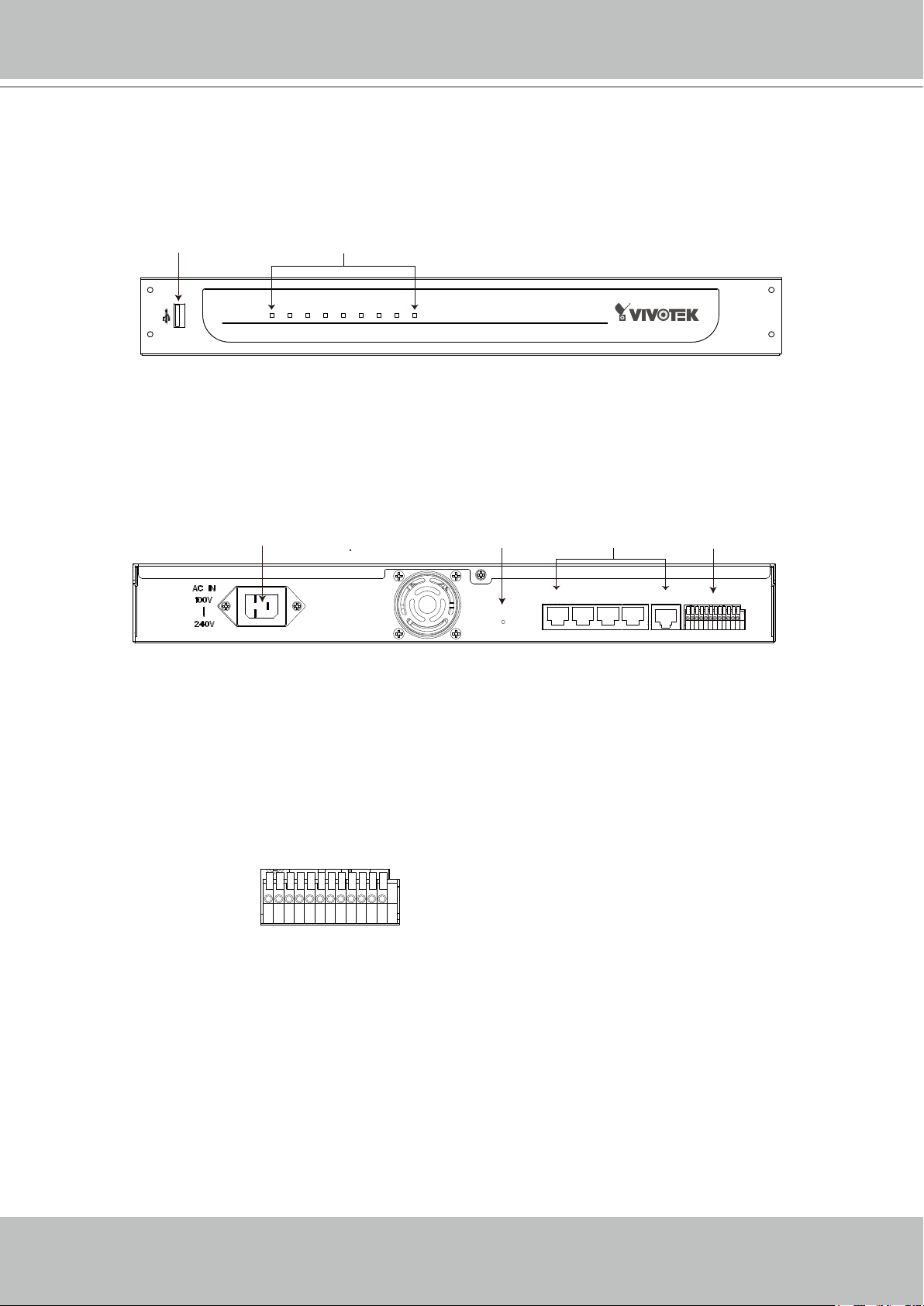
1 2 3 4 5 6 7 8 9 10 11 12
Power POE Status HDD WAN LAN1 LAN2 LAN3 LAN4
USB socket
Status indicator
NR7401 Network Video Recorder
RESET
LAN4 LAN3 LAN2 LAN1
WAN
1 2 3 4 5 6 7 8 9 10 11 12
Power cord socket
Indented reset button
General I/O
terminal block
Ethernet 10/100
RJ45 socket
Physical description
Front panel
Connectors
General I/O Terminal Block
This Network Camera provides a general I/O terminal block which is used to connect external
input / output devices. The pin denitions are described below.
1: Power
2: Relay output COM
3: Relay output N�O�
4: Digital Input 1
5: Digital Input 1 Ground
6: Digital Input 2
7: Digital Input 2 Ground
8: Digital Input 3
9: Digital Input 3 Ground
10: Digital Input 4
11: Digital Input 4 Ground
12: Ground
Page 5
VIVOTEK - A Leading Provider of Multimedia Communication Solutions
User's Manual - 5
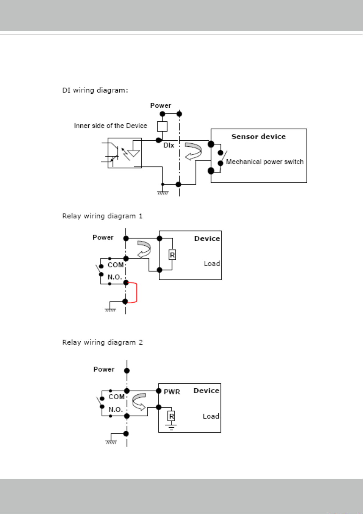
DI/DO Diagram
Refer to the following illustration for connection method�
Page 6

VIVOTEK - A Leading Provider of Multimedia Communication Solutions
6 - User's Manual
Status LED
The LED indicates the status of the Network Video Recorder�
LED Status Indication
Power Green Power on
Off Power off
POE Green Normal
Off Power off / POE fail
Status Green Normal
Blinking red Upgrading firmware
HDD (Hard disk) Blinking green Hard disk is accessed
Red Hard disk full or error
WAN On With connection
Off No connection
Blink Activity on WAN port
LAN1 On With connection
Off No connection
Blink Activity on LAN port 1
LAN2 On With connection
Off No connection
Blink Activity on LAN port 2
LAN3 On With connection
Off No connection
Blink Activity on LAN port 3
LAN4 On With connection
Off No connection
Blink Activity on LAN port 4
Hardware System Requirement
Computer:
■ Microsoft Windows XP Professional SP2 or above
■ Internet Explorer 6�0 or later
Hard disk:
SATA hard drive for up to 1TB
Hardware Reset
There is a indented reset button on the back panel of the Network Video Recorder� It is used to
reboot the Network Video Recorder or restore the Network Video Recorder to factory default�
Sometimes rebooting the Network Video Recorder could set it back to normal state� If the
problems remain after rebooted, restore the Network Video Recorder to factory default and
install again�
Page 7
VIVOTEK - A Leading Provider of Multimedia Communication Solutions
User's Manual - 7
2
5
3
4
6
7
Power POE Status HDD WAN LAN1 LAN2 LAN3 LAN4
NR7401 Network Video Recorder
Reboot: Press and release the indented reset button� All status LED will extinguish and then
power on again. Wait for the Status LED to blink and then become steady green in normal state.
It takes about 30 seconds to complete the procedure�
Restore: Press the reset button continuously for over 3 seconds� All status LED will extinguish
and then power on again. Wait for the Status LED to blink and then become steady green in
normal state� Note that all settings will be restored to factory default� It takes about 50 seconds
to complete the procedure�
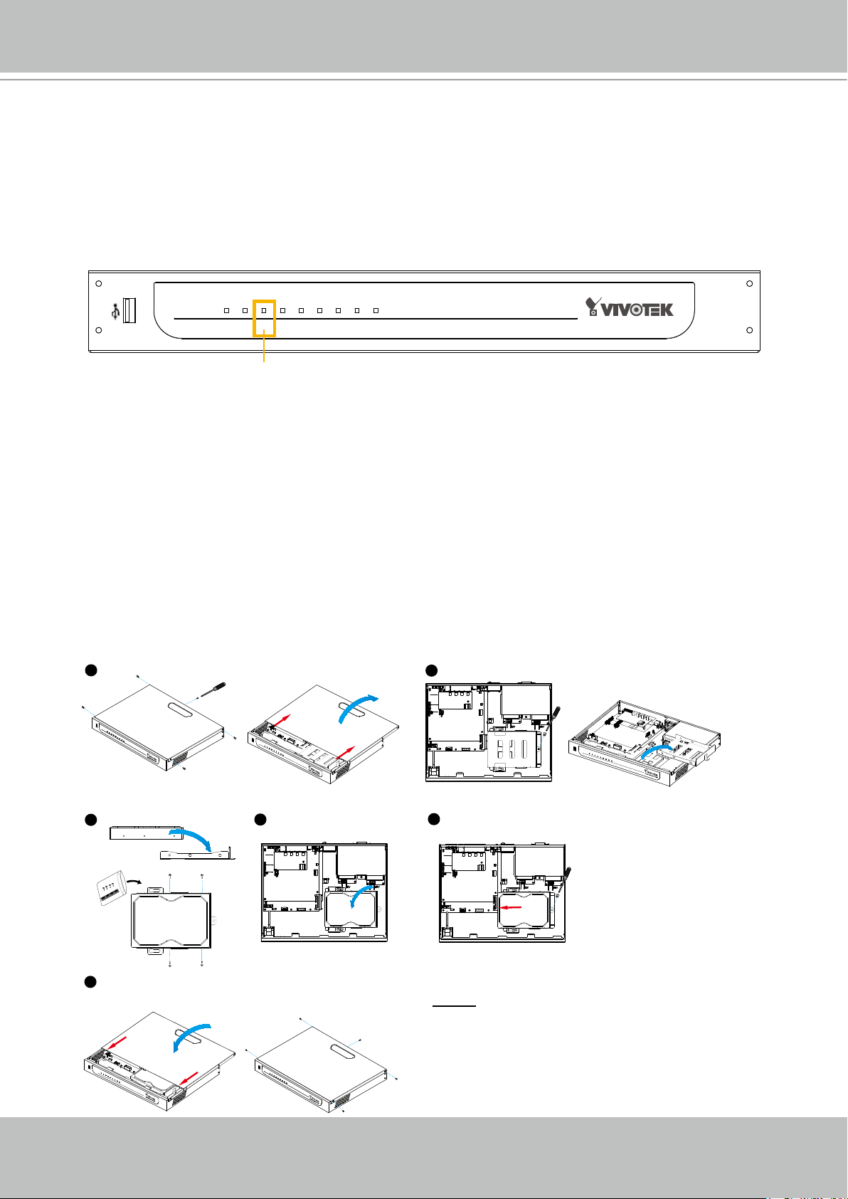
Steady green in normal state
Installation
Hard Disk installation
Before using the Network Video Recorder, the rst step is to install a SATA hard disk for re-
corded video� Please follow the steps below:
1� Make sure the power is off�
2. Use a screwdriver to loose ve screws, and then slide to remove the upper cover.
3� Loose the screw and take out the hard disk bracket�
4� Put your hard disk into the bracket, and secure it with the supplied four screws�
5� Place your hard disk into the Network Video Recorder�
6� Slide the hard disk as the picture shows, and then secure it with the original screw�
7. Attach the upper cover, and then secure it with the original ve screws.
NOTE
► Please remember to format the hard disk
before strating recording� Please refer to
maintenance on page 37�
Page 8
VIVOTEK - A Leading Provider of Multimedia Communication Solutions
8 - User's Manual
RESET
LAN4 LAN3 LAN2 LAN1
WAN
1 2 3 4 5 6 7 8 9 10 11 12
Activity
Power/MIC
Inte r net
WAN
LAN
LAN
LAN
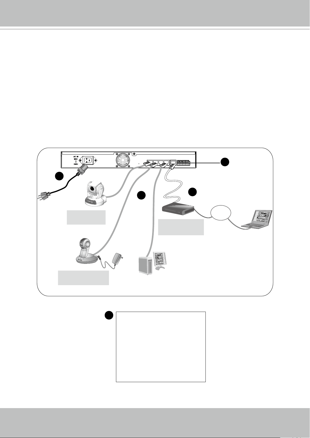
Network deployment
Device Connection
1� Connect the supplied power cable from the NR7401 to a power outlet�
2� Connect NR7401 to Network Cameras and computer in LAN via LAN sockets� Because
NR7401 supports PoE, if the Network Camera is PoE-compliant (802�3af), it allows transmission
of power and data via single Ethernet cable�
3� If your want to access NR7401 over the Internet, connect NR7401 to the Internet via WAN
socket�
4� If you have external devices such as sensors and alarms, make connections from general I/O
terminal block�
4
1
3
Network Camera
(PoE)
Network Camera
(without PoE)
2
1: Power
4
2: Relay output COM
Cable, DSL
Modem, or router
3: Relay output N�O�
4: Digital Input 1
5: Digital Input 1 Ground
6: Digital Input 2
7: Digital Input 2 Ground
8: Digital Input 3
9: Digital Input 3 Ground
10: Digital Input 4
11: Digital Input 4 Ground
12: Ground
Page 9
VIVOTEK - A Leading Provider of Multimedia Communication Solutions
User's Manual - 9
Getting Started
Please follow the steps below to link your computer to NR7401 for the rst time:
1� Connect your computer to NR7401 (LAN port) using an Ethernet cable�
2� Setup your computer in DHCP mode�
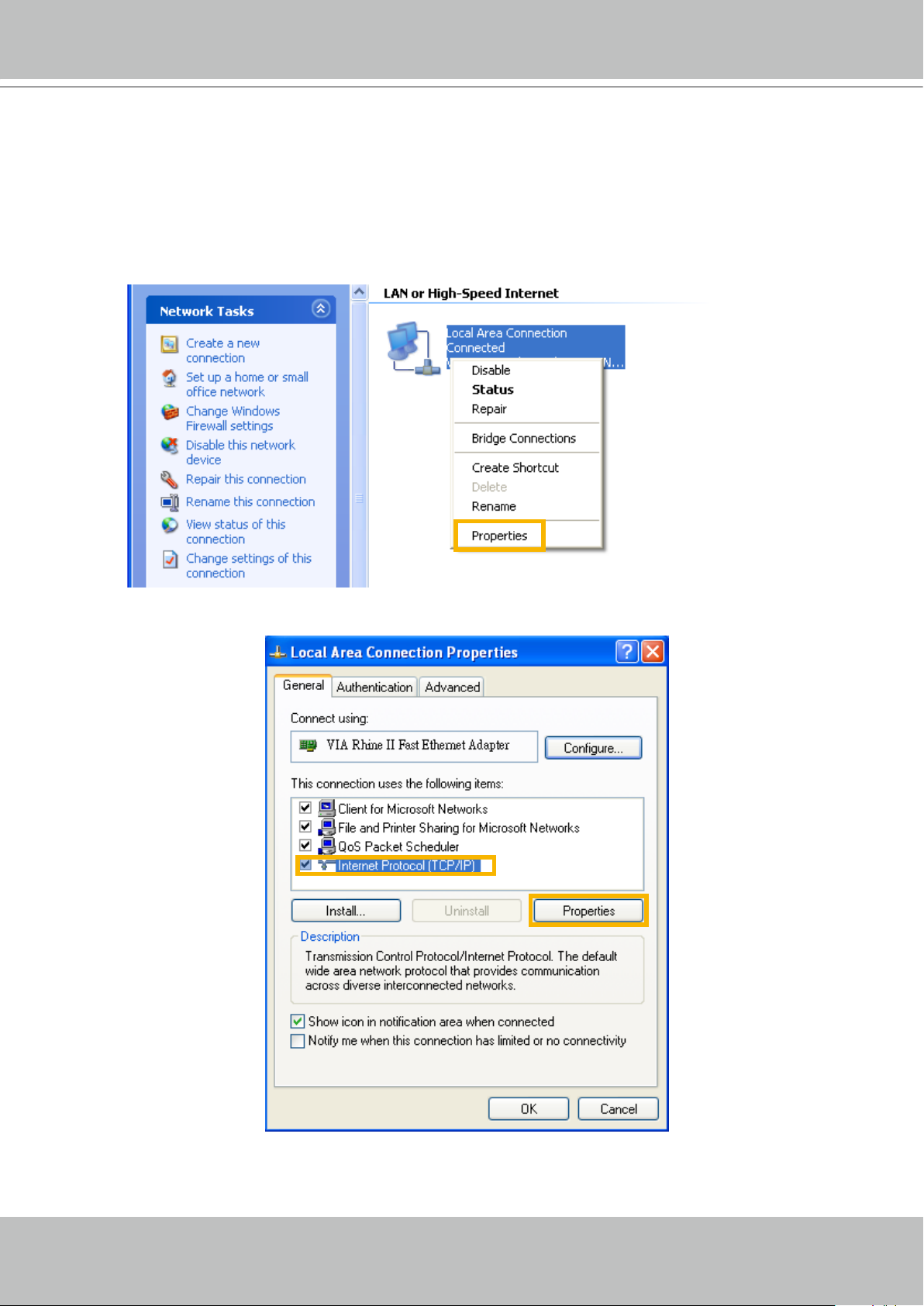
a� Click Start > My Network Places > View network connections�
b� Right-click Local Area Connection, and then click Properties�
c� Select Internet Protocol (TCP/IP), and then click Properties�
Page 10
VIVOTEK - A Leading Provider of Multimedia Communication Solutions
10 - User's Manual
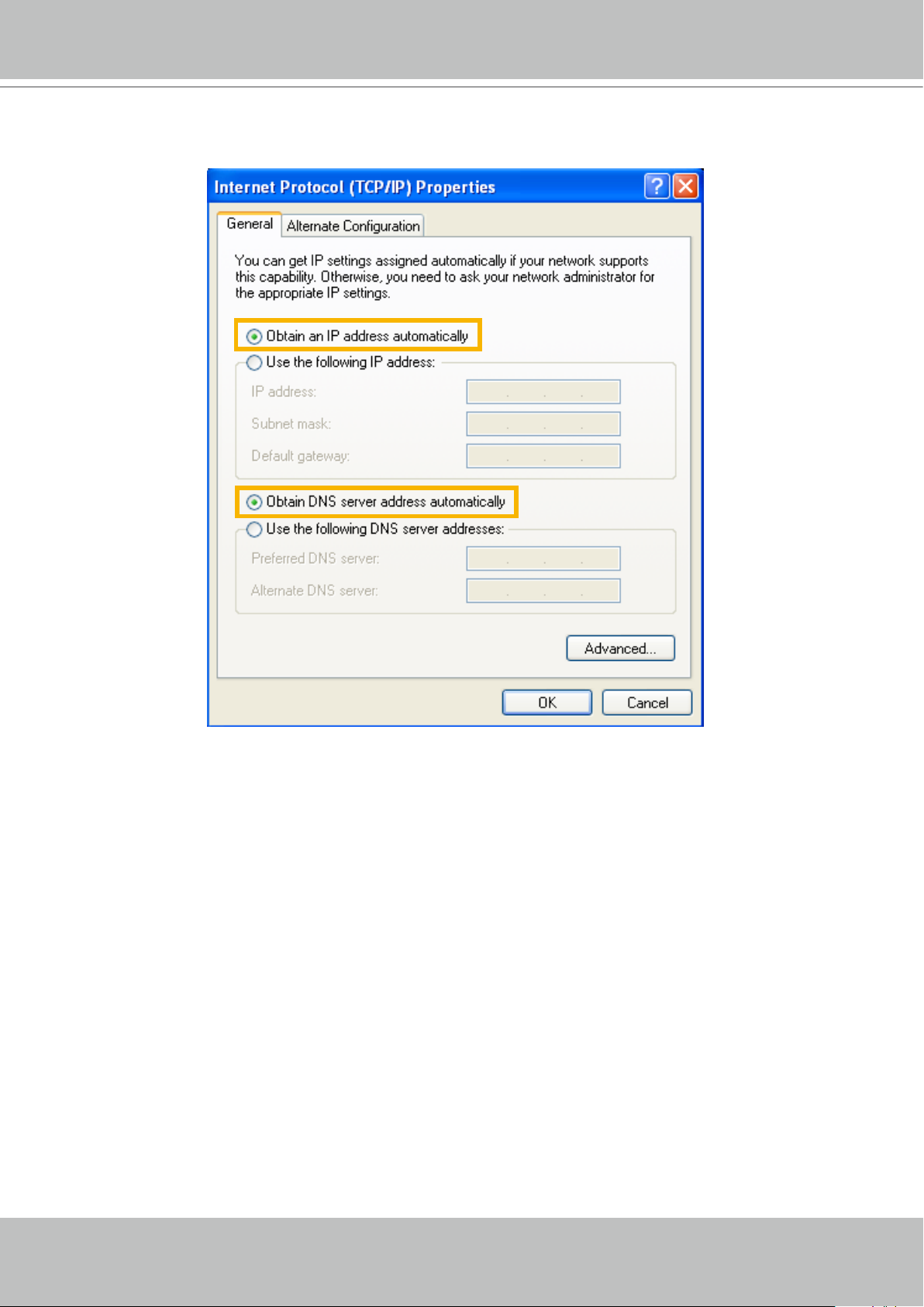
d� Select "Obtain an IP address automatically" and "Obtain DNS server address automatically"
as below� Then click OK to enable your settings�
3� Then NR7401 will server as a router and automatically assign an IP address to your computer�
Page 11
VIVOTEK - A Leading Provider of Multimedia Communication Solutions
User's Manual - 11
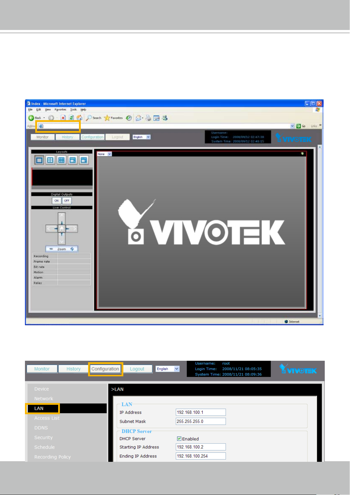
http://192.168.100.1/
Setup NR7401 in LAN
To setup NR7401 for the rst time, please refer to page 9 to setup your computer in DHCP
mode, and then directly enter the default IP address for NR7401 (http://192�168�100�1) in the
addrees bar of the web browser� The webpage of the Network Video Recorder will be displayed
for you to congure the settings.
LAN Settings Conguration
Go to Conguration > LAN to verify the settings as below�
Page 12
VIVOTEK - A Leading Provider of Multimedia Communication Solutions
12 - User's Manual
WAN Settings Conguration
If you want to access the Network Video Recorder over the Internet, please go to Conguration
> Network to assign a WAN IP address (public IP) for NR7401. There are three ways to get a
WAN IP address: Privite DHCP (Dynamic IP), Static IP address, and PPPoE (DSL)�
Internet connection with private DHCP (dynamic IP)
Choose this connection type to automatically obtain a dynamic IP address assigned by a DHCP
server� Please follow the steps below to verify the settings:
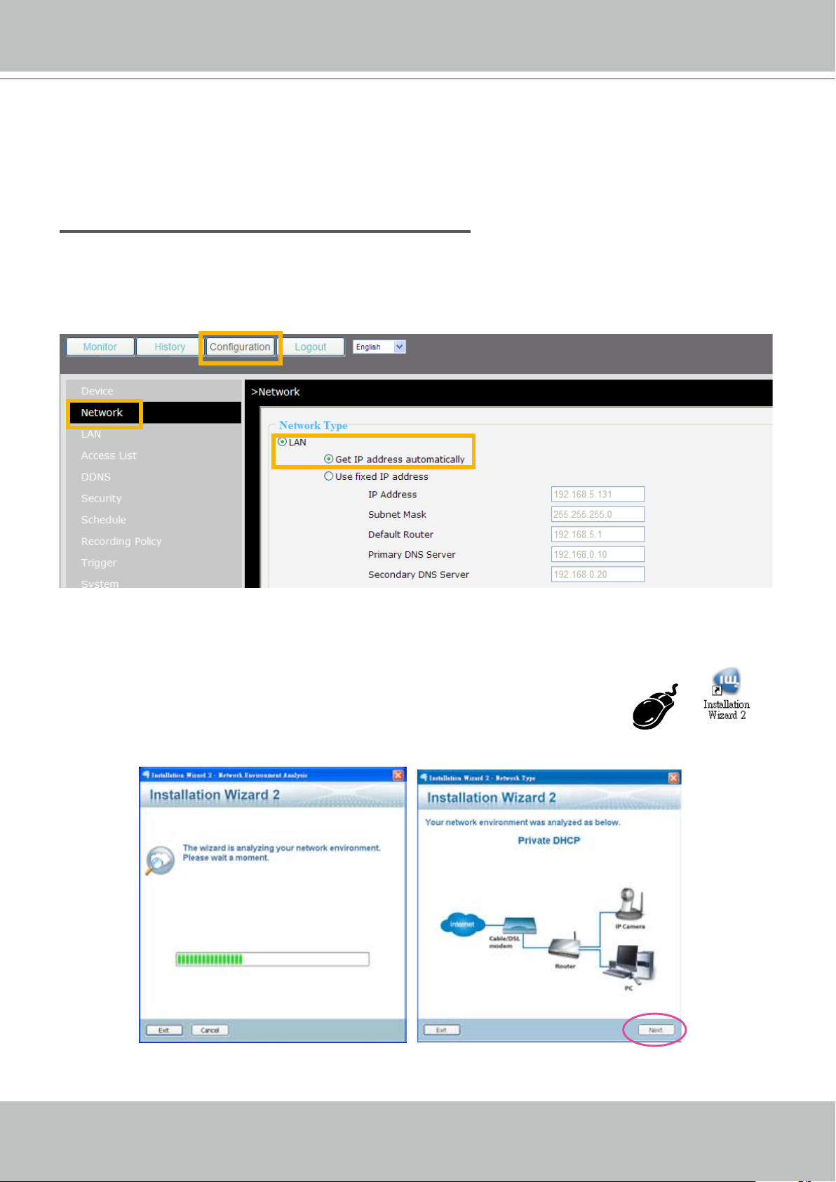
1� Go to Conguration > Network� Click LAN > Get IP address automatically.
2� Click Apply to enable the settings�
3. If your computer is in the same domain with the WAN IP address, then you can use VIVOTEK
Installation Wizard 2 (IW2) to search for the Network Video Recorder easily.
Please follow the steps below to run IW2:
a. Install the IW2 under the Software Utility directory from the software CD.
Double-click the IW2 shortcut on your desktop to launch the program.
b� The program will conduct analyses on your network environment�
After your network environment is analyzed, please click Next to continue the program.
c� The program will start search for all VIVOTEK devices in the same LAN�
Page 13
VIVOTEK - A Leading Provider of Multimedia Communication Solutions
User's Manual - 13
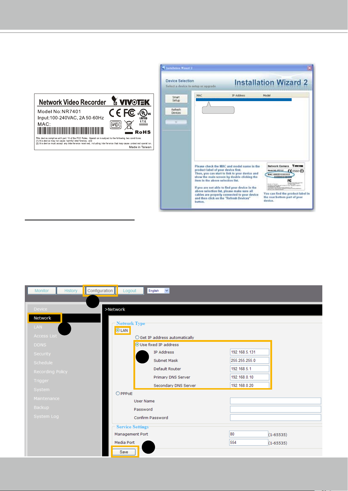
0002D171893F
00-02-D1-07-89-3F 192.168.5.131 NR7401
0002D107893F
d� After searching, the main installer window will pop up� Click on the MAC and model name
which match the product label on your device to connect to the Network Video Recorder�
Internet connection with static IP
Choose this connection type if you want to use a static IP for the Network Video Recorder�
Please follow the steps below to change the settings:
1� Go to Conguration > Network� Click LAN > Use xed IP address�
2� Enter the static IP, Subnet Mask, Default Router, Primary DNS Server provided by your ISP�
3� Click Save to enable the settings�
1
2
3
4
Page 14
VIVOTEK - A Leading Provider of Multimedia Communication Solutions
14 - User's Manual
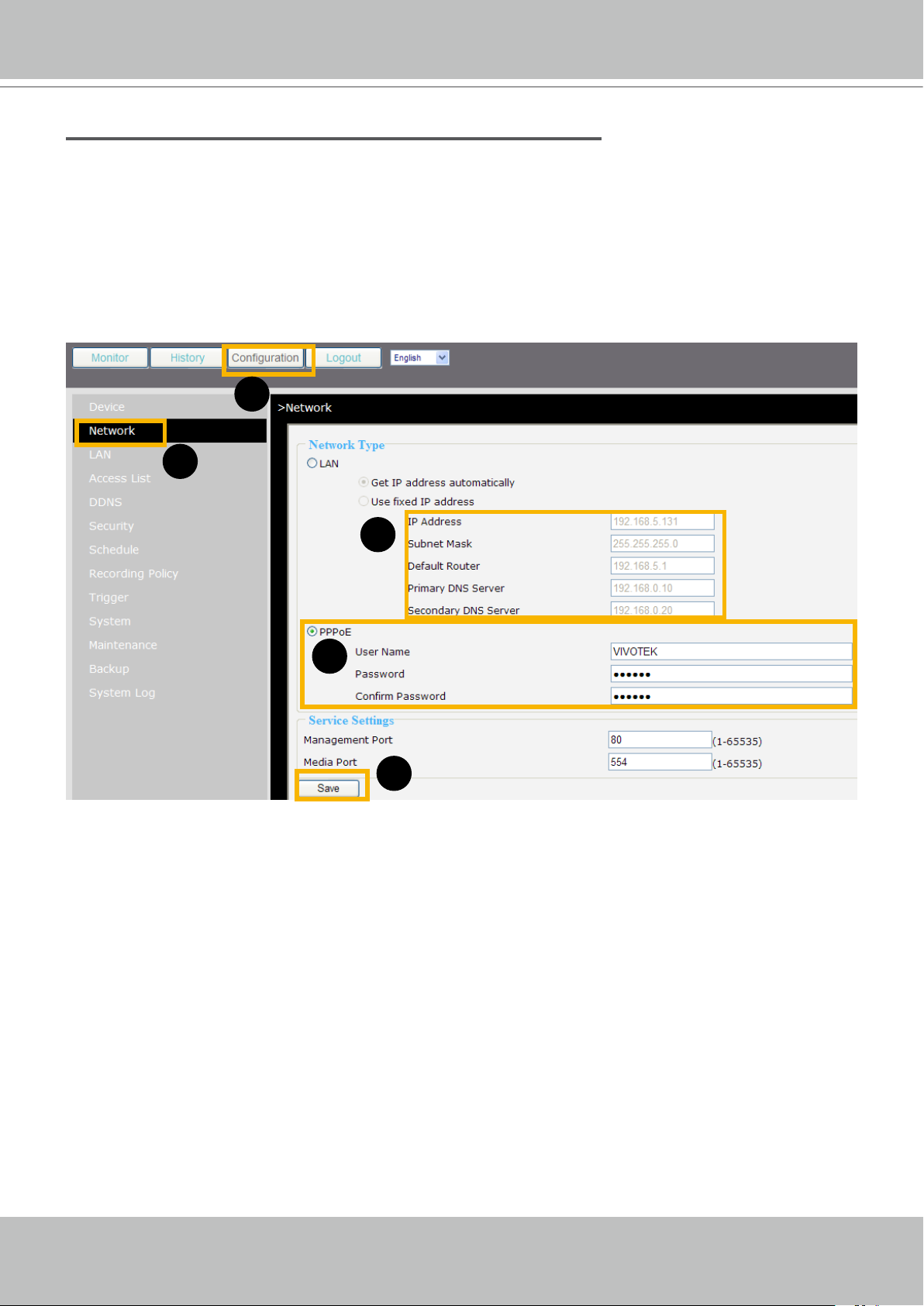
Internet connection via PPPoE (Point-to-Point over Ethernet)
Choose this connection type if you are connected to the Internet via a DSL Line� Please follow
the steps below to change the settings:
1� Go to Conguration > Network� Click PPPoE�
2� Enter the User Name and Password provided by your ISP�
3� Click Save to enable the settings�
4� The IP Address, Subnet Mask, Default Router, Primary DNS Server will automatically show up in the
above blanks�
1
2
5
3
4
Page 15
VIVOTEK - A Leading Provider of Multimedia Communication Solutions
User's Manual - 15
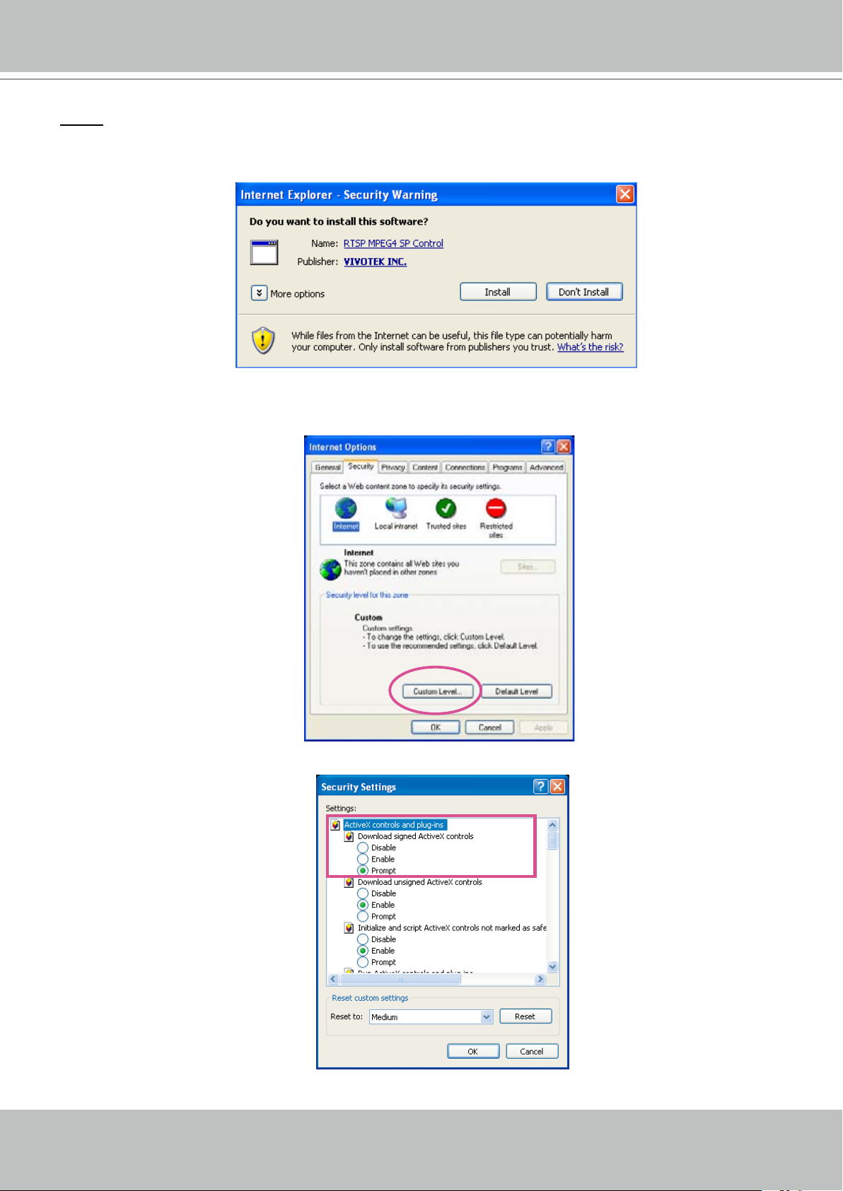
NOTE
► When attempting link to NR7401 for the rst time with the web browser, a message will pop up to
remind you to install required plug-in or software rst.
► If you receive a message saying that your Internet Explorer® security settings prohibit installing
Active X® components, please enable your Active X® Controls for your browser�
1� Click Tools > Internet Options > Security > Custom level... on the tool bar of the Internet browser�
2. Look for Download signed ActiveX® controls; select Enable or Prompt� Click OK�
3. Refresh your web browser, and then install the Active X®. Follow the instructions to nish installation.
Page 16
VIVOTEK - A Leading Provider of Multimedia Communication Solutions
16 - User's Manual
http://192.168.100.1/
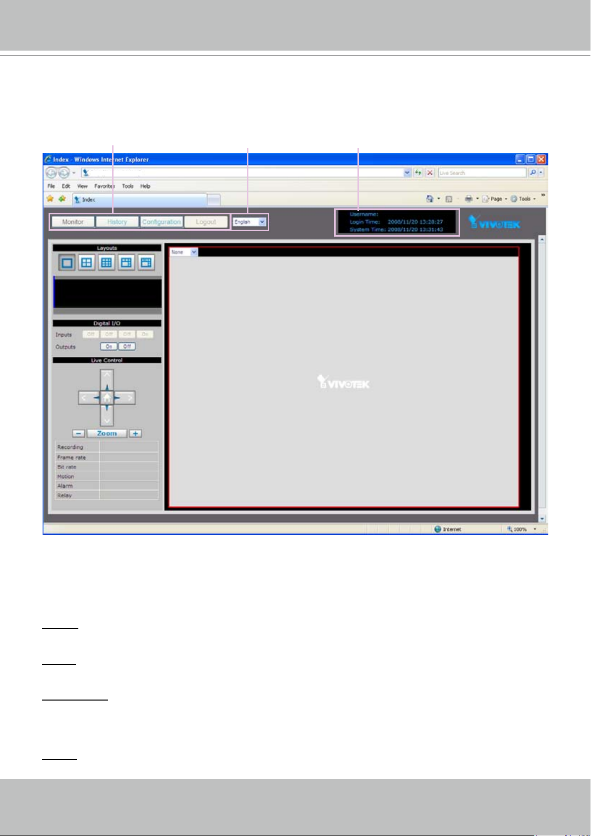
Main menu
Status panel
Language
Home Page
Following is the user interface of the home page� It is composed of the following sections�
Main menu
There are four buttons for you to click to open the page:
Monitor: Click this button to open the Monitor page� This page is for you to see the live video or playback
the recorded data�
History: Click this button to open the History page� This page is for you to search and playback recorded
data in a specic range of time.
Configuration: Click this button to open the Configuration page� This page is for you to configure the
settings of the network video recorder� It is suggested that a password is applied to the Network Video
Recorder, so that only the authorized user can congure the settings. Please refer to page 18 for detailed
information�
Logout: Click this button to logout the home page� This button will be enabled if you set up a root
password in the Security page� Please refer to page 25 for detailed information�
Page 17

VIVOTEK - A Leading Provider of Multimedia Communication Solutions
User's Manual - 17
Language
Click the drop-down list to choose a language for the user interface� Language options are
available in: English and
簡体中文.
Status panel
User Name (default: root)
Login Time (yyyy-mm-dd hh:mm:ss)
Current Time (yyyy-mm-dd hh:mm:ss)
NOTE
► The Username will be blank if you have not setup a password in the Security page. Please refer to
page 25 for detailed information�
► Depending on user’s privilege of the user account, the access to the congutation page may be
restricted� For more information about user’s privilege, please refer to Manage Privilege on page 26�
Page 18

VIVOTEK - A Leading Provider of Multimedia Communication Solutions
18 - User's Manual
Conguration
This page contains several sub-pages: “Device”, “Network”, “Access list”, “LAN”, “DDNS”,
“Security”, “Schedule”, “Recording policy”, “Trigger”, “Backup”, “System”, and “Maintenance”�
Each sub-page in the left menu will be explained in the following sections�
Device
This page allows user to add a new device or modify an inserted device� NR7401 supports
simultaneous 9-CH video recording�
Following is the current support list of NR7401:
7000 series 6000 series
IP7135 / 7137 IP6112/6122
IP7131 / 7132 IP6117/6127
IP7138 / 7139 PZ6112/6122
IP7142 PZ6114/6124
IP7151 / 7152 FD6111V/6121V
IZ7151 FD6112V/6122V
PT7135 / 7137 SD6112V/6122V
PZ7151 / 7152
PZ7111 / 7121 / 7112 / 7122
FD7131
FD7132
FD7141
SD7151
VS7100
Page 19

VIVOTEK - A Leading Provider of Multimedia Communication Solutions
User's Manual - 19
Auto search by device installer or manually install in LAN
If your devices are linked to the LAN port of the Network video Recorder, you can follow the
steps below to add a new device by the Installer:
1� Select Add new on the drop-down list
2� Click Start Searching� The searching results will be displayed in the following column� You can click
Stop Searching if the linked devices are all displayed on the list�
3� Select a device to be inserted� Modify the Device Name if necessary�
4� Click Add Device to enable the settings�
1
3
2
4
You can also manually install a new device in LAN�
Please follow the steps below:
1� Select Add new on the drop-down list
2� Enter the Device Name�
3� Enter the Username/Password if the device needs to do authentication�
4� Select the Device Type� Please refer to page 18 for support list�
5� Enter the MAC Address of the device in the format as xx:xx:xx:xx:xx:xx�
6� Enter the HTTP Port for the device�
7� Click Save to enable the settings�
Page 20

VIVOTEK - A Leading Provider of Multimedia Communication Solutions
20 - User's Manual
Manually install in WAN
When in WAN, you have to add a new device manually� Please follow the steps below:
1� Select Add new on the drop-down list
2� Enter the Device Name�
3� Enter the Username/Password if the device needs to do authentication�
4� Select the Device Type� Please refer to page 18 for support list�
5� Enter the MAC Address of the device in the format as xx:xx:xx:xx:xx:xx�
6� Enter the IP Address of the device� You can leave this blank empty if the IP address is assigned
automatically by the NR7401 server�
7� Enter the HTTP Port for the device�
8� Click Save to enable the settings�
NOTE
► If you want to modify the settings of the device, select it on the drop-down list.
The device information will be displayed in the following blanks, then you can modify the settings of
the device�
►
By default, the recording schedule is “Always“ (continuous recording)� If you want to modify the
recording schedule, please refer to page 27 for detailed information�
►
By default, the recording policy is “Default“ mode� If you want to modify the recording policy, please
refer to page 29 for detailed information�
►
Alarms refers to digital input of the device; Relays refers to digital output of the device� These two
columns will not show up if the linked device does not have external DI/DO�
Page 21

VIVOTEK - A Leading Provider of Multimedia Communication Solutions
User's Manual - 21
RESET
LAN4 LAN3 LAN2 LAN1
WAN
1 2 3 4 5 6 7 8 9 10 11 12
Activity
Power/MIC
LAN
LAN
LAN
IP address: 192.168.100.1
Subnet mask: 255.255.255.0
IP address: 192.168.100.2
Subnet mask: 255.255.255.0
IP address: 192.168.100.3
Subnet mask: 255.255.255.0
IP address: 192.168.100.4
Subnet mask: 255.255.255.0
Network (WAN)
This page allows user to configure WAN configuration for the Network Video Recorder. It
contains two columns: “LAN” and “DHCP Server�“ Please refer to page 12~15 for detailed
settings�
LAN / DHCP Server
This page allows Administrators to configure network connection in LAN for the Network
Video Recorder. It contains two columns: “LAN” and “DHCP Server.“ When in LAN, the default
IP Address for the Network Video Recorder is 192�168�100�1� The default Subnet Mask is
255�255�255�0�
If you set up the network video recorder in LAN and link its LAN Port to network cameras
and computer as the picture shows below, the DHCP server of network video recorder will
automatically assign IP address to those linked devices� (192�168�100�2 ~ 192�168�100�254)
NOTE
► The starting and ending address of the DHCP server must be in the same subnet as the IP address of
the LAN interface of the NR7401�
Page 22

VIVOTEK - A Leading Provider of Multimedia Communication Solutions
22 - User's Manual
Alowed
List
Denied
List
Access list
This page allows user to setup the access permission for the Network Video Recorder by
checking the client PC’s IP addresses� It is composed of the following four columns: “Allowed
List”, “Delete Allowed list”, “Denied List”, and “Delete Denied List”�
Allowed list / Denied list
There are two lists for permission control: Allowed list and Denied list� Only those clients whose IP
addresses are in the Allowed list and not in the Denied list can access the Network Camera�
1� In the Allowed list or Denied list column, type the starting IP address and ending IP address in the text
boxes. A total of 10 lists can be congured for both columns.
2� Click Add to take effect�
NOTE
► For example, when the range of allowed list is set from 1.1.1.0 to 192.255.255.255 and the range
of denied list is set from 1�1�1�0 to 170�255�255�255, Only users’ IP located between 171�0�0�0 and
192�255�255�255 can access the Network Camera�
Delete allowed list / Delete denied list
1� In the Delete allowed list or Delete denied list, select a list from the drop-down list�
2� Click Delete to take effect�
Page 23

VIVOTEK - A Leading Provider of Multimedia Communication Solutions
User's Manual - 23
DDNS
This page allows user to configure dynamic domain name service for the Network Video
Recorder� DDNS (Dynamic domain name service) is a service that allows your Network Video
Recorder, especially when assigned with a dynamic IP address, to have a xed host and domain
name�
DDNS Settings
Select DDNS Service: Select a DDNS provider from the Provider drop-down list�
VIVOTEK offers Safe100�net, a free dynamic domain name service to VIVOTEK customers� It is
recommended that you register with the Safe100�net to access the Network Video Recorder from the
Internet� Additionally, we offer other DDNS providers, such as Dyndns�org, DHS�org, TZO�com, dyninterfree�it�
Note that to utilize this feature, please apply a dynamic domain account rst.
■ Safe100�net
1� Select www�safe100�net on the Provider drop-down list�
2� Click I Accept when you agree with the terms of the Service Agreement�
Page 24

VIVOTEK - A Leading Provider of Multimedia Communication Solutions
24 - User's Manual
3. In the Register column, ll in the Host name, Email, Key and Conrm Key and then click Register�
You will receive a “Self registration E-mail” which records your account information�
4� Back to the DDNS settings window, enter your account information and then click Save to enable
the settings�
Forget key: Click this button if you forget the key of Safe100�net� Your account information will be sent to
your e-mail address�
Please refer to the following links to apply a dynamic domain account when selecting other
DDNS providers:
■ Dyndns�org (Dynamic) / Dyndns�org (Custom): visit http://www�dyndns�com/
■ TZO�com: visit http://www.tzo.com/
■ DHS�org: visit http://www�dhs�org/
■ dyn-interfree�it: visit http://dyn-interfree�it/
Page 25

VIVOTEK - A Leading Provider of Multimedia Communication Solutions
User's Manual - 25
Security
This page allows Administrator to enable password protection and create multiple user accounts
for the Network Video Recorder� It is composed of the following three columns: “Root Password”,
“Manage Privilege“, and “Manage User”�
Root Password
If you want to add more accounts in Manage User column, please apply a password for the “root”
account rst. Please follow the steps below to set up root password:
1� Enter the password identically in both text boxes�
2� Click Save to enable password protection�
3� The home page will automatically change to a login page as below� Enter the administrator username
as “root”, which is permanent and can not be changed� Enter the root password you’ve just inserted,
and then click Login to link to the home page�
3� The Logout button on the Main Menu will be enabled after you set up a root password�
Page 26

VIVOTEK - A Leading Provider of Multimedia Communication Solutions
26 - User's Manual
Manage Privilege
In this section, you can modify the manage privilege of operators or viewers� Check or uncheck
the item, and then click Save to take effect�
Following is the privilege list of different user accounts:
User privileges Administrator Operator Viewer
System Configuration O X X
Device Configuration O O X
Live Control (Monitor page) O O O
Playback Control (History page) O O O
NOTE
► The user privileges of an administrator are always enabled and cannot be changed.
► Operator and Viewer doesn’t heve the permission to access the Conguration page.
Manage User
■
Administrator can add up to twenty user accounts�
1� Enter the new user’s name and password�
2� Select the Privilege for new user account� Click Save to take effect�
■
Here you also can change user’s privilege or delete user accounts�
1� Select an account on the drop-down list�
2� Make necessary changes and then click Save or Remove to take effect�
NOTE
► NR7401 allows up to 10 users to login to the webpage simultaneously�
Page 27

VIVOTEK - A Leading Provider of Multimedia Communication Solutions
User's Manual - 27
Schedule
This page allows Administrator to add a new Recording Schedule or modify an existing
Schedule for the Network Video Recorder� You can configure up to 16 recording schedules
based on a weekly basis�
By default setting, all inserted device are assigned to the default recording schedule (always)�
Therefore, once you insert a device to the network video recorder, it will begin to record live
video continuously�
■
Please follow the steps below to add a new recording schedule:
1� Enter a descriptive name for the new schedule�
2� Select a day and enter a time frame (in the format of 24hr)�
3� Click Add to take effect� The new recording schedule will show up in the Schedule Display column�
You can add more than one time frames�
Following is an example of recording schedule (Mon�~Fri� 09:00~12:00)�
4� Click Save to enable the settings�
Page 28

VIVOTEK - A Leading Provider of Multimedia Communication Solutions
28 - User's Manual
■ The new recording schedule will show up on the device information as below. Click Device on
the left main Menu� Then you can select Always, Never, or schedule1 as your recording
schedule�
■ The new recording schedule will also show up on the Trigger Conguration as below. Click
Trigger on the left Menu� Then you can select Always, Never, or schedule1 as your
schedule for event trigger�
■ If you want to delete a recording schedule, select it on the drop-down list (Select Schedule)
and then click Remove to delete it�
■ If you want to delete a time frame, select it on the drop-down list (Delete Entry) and then click
Delete�
Page 29

VIVOTEK - A Leading Provider of Multimedia Communication Solutions
User's Manual - 29
Recording Policy
This page allows user to set up recording policy for linked devices� By default setting, all
inserted device are assigned to the default recording schedule (always), default recording type
(continuous mode), and default recording policy (save scheduled recording--1 hour)�
Therefore, once you insert a device to the network video recorder, it will begin to record live
video continuously but only save “1 hour“ recorded video clips� The recorded video will be
displayed on the History page�
For example:
The user added a VIVOTEK FD7132 to NR7401� Following pictures shows the default settings:
■ Conguration > Device
■ Conguration > Recording Policy
■ Recorded video clips on History page (only 1 hour video clips are saved in the hard disk)
When the range of time is over 1 hour, the rst video clip will be erased. For detailed information
about the History page, please refer to page 45�
Page 30

VIVOTEK - A Leading Provider of Multimedia Communication Solutions
30 - User's Manual
This page allows Administrator to add a new Recording Policy/Recording Type or modify
an existing recording policy/Recording Type for the Network Video Recorder� The user can
congure up to 4 recording policies.
■ Please congure the following items to add a new Recording Policy/Recording Type:
Recording Policy
Select Policy: Select Add new�
Name: Enter a descriptive name for the new recording policy�
Save Scheduled Recording:
Motion Recording: Select a time period (1 Hour, 1 Day, 1 Week, 2 Weeks, 30 Days, or 90 Days).
Pre-motion Time: Select a time period (0 Seconds, 10 Seconds, 30 Seconds, 1 Minute, or 5 Minutes)�
Post-motion Time: Select a time period (30 Seconds, 1 Minute, or 5 Minutes)�
Save Alarm Recording: Select a time period (1 Hour, 1 Day, 1 Week, 2 Weeks, 30 Days, or 90 Days).
Pre-alarm Time: Select a time period (0 Seconds, 10 Seconds, 30 Seconds, 1 Minute, or 5 Minutes)�
Post-alarm Time: Select a time period (30 Seconds, 1 Minute, or 5 Minutes)�
Save Manual Recording: Select a time period (1 Hour, 1 Day, 1 Week, 2 Weeks, 30 Days, or 90 Days).
Select a time period (1 Hour, 1 Day, 1 Week, 2 Weeks, 30 Days, or 90 Days).
Recording Type
Disabled: No recording�
Event Mode: Start to record if Motion triggered or Alarm triggered within the recording schedule� Please
note that the priority of Alarm trigger would be higher than Alarm trigger�
Continuous Mode: Record all video within the recording schedule�
Following is an example of recording policy:
Click Save to take effect�
■
Page 31

VIVOTEK - A Leading Provider of Multimedia Communication Solutions
User's Manual - 31
■ The new recording policy will show up on the device information as below. Click Device on the
left Menu� Then you can select Default or policy1 as your recording policy�
■ If you want to delete a recording policy, select it on the drop-down list and then click Remove
to delete it�
Page 32

VIVOTEK - A Leading Provider of Multimedia Communication Solutions
32 - User's Manual
ex. Camera Disconnected,
Motion detection on/off,
Alarm on/off (Digital input)...
Event Trigger
ex. Snapshot or .txt file
ex. Email, FTP
Media
(what to send)
Server
(where to send)
ex. Turn on/off Relay
(Digital output)
NR7401
(what to do)
Action
(what to do)
Trigger
This page allows Administrator to congure the Network Video Recorder to react in response
to particular event triggers� A typical reaction is that when a motion is detected by the network
camera, the Network Video Recorder sends buffered images to a FTP server or e-mail address
as notications. You can congure up to 16 event triggers.
In the following illustration, an event can be triggered by many sources, such as motion
detection or external alarm (digital input devices). When an event is triggered, you can specify
what kind of action should be performed� You can assign the Network Video Recorder to send
snapshots (�jpg) or �txt document to your e-mail address or FTP site�
■
Please congure the following items to please follow the steps below to add a new event trigger:
Page 33

VIVOTEK - A Leading Provider of Multimedia Communication Solutions
User's Manual - 33
Trigger Conguration
Select Trigger: Select Add new�
Name: Enter a descriptive name for the new event trigger�
Schedule: Select a recording schedule on the drop-down list (Always, Never, or other recording
schedule)�
Trigger Event
1� From linked devices
Select one of the following event source, and then select a linked device�
Camera Disconnected: Linked Device is disconnected�
Camera Motion On: Motion detection window is triggered on linked Device�
Camera Motion Off: Motion detection window is stopped on linked Device�
Camera Video Lost On: Video lost happens on linked Device (ex� VIVOTEK video server VS7100)�
Camera Video Lost Off: Video lost ends on linked Device (ex� VIVOTEK video server VS7100)�
Alarm On: Alarm (external digital input) is triggered on linked Device� This function will only be enabled
on the devices with DI function�
Alarm Off: Alarm (external digital input) is off on linked Device� This function will only be enabled
on the devices with DI function�
2� From the network video recorder
Select one of the following source; and then select a digital input�
Alarm On: Alarm (external digital input di0~di4) is triggered on the network video recorder�
Alarm Off: Alarm (external digital input di0~di4) is off on the network video recorder�
NOTE
► You can modify the the Name and priority of digital inputs on the network video recorder� Please refer
to Digital Input on page 32 for detailed information�
Trigger Action
To plot an event trigger, please select one of a following action so that the Network Video
Recorder will know what action should be performed when a trigger is activated�
1� Actions of the system
Please click System on the left main menu to congure E-mail server or FTP server settings rst.
Please refer to page 35 for detailed conguration.
Email Notication: Send a snapshot to user’s e-mail address�
FTP Notication: Send a snapshot to user’s FTP site�
Page 34

VIVOTEK - A Leading Provider of Multimedia Communication Solutions
34 - User's Manual
2� Actions of the linked devices
Turn On Relay: Turn on Relay (digital output) on linked device� This function will only be enabled on
the devices with DO function�
Turn Off Relay: Turn off Relay (digital output) on linked device� This function will only be enabled on
the devices with DO function�
3� Actions of the network video recorder
Turn On Relay: Turn on Relay (digital output do0) on the network video recorder�
Turn Off Relay: Turn off Relay (digital output do0) on the network video recorder�
NOTE
► You can modify the the Name of digital outputs on the network video recorder� Please refer to Digital
Input on page 36 for detailed information�
► E-mail & FTP notication
1� E-mail format:
Event Type Camera disconnected Motion on Motion off Alarm on Alarm off
Title Camera disconnected Motion on Motion off Alarm on Alarm off
Content Camera Y is disconnected
With Snapshot
(jpg)
No Yes Yes Yes Yes
Motion X triggered
on Camera Y
Motion X stopped
on Camera Y
Alarm trigger
on Camera Y
Alarm off on
Camera Y
2� FTP format
Event
Type
File name
Content
■
The “Y” in Device Y means the Device Name on NR7401, the “X” in Motion X means the Xth motion
Camera disconnected Motion on Motion off Alarm on Alarm off
Date_CamDisconnect�txt Date_Motionon�jpg Date_Motionoff�jpg Date_Alarmon�jpg
Camera Y is disconnected
Snapshot image Snapshot image Snapshot image Snapshot image
Date_Alarmoff�jpg
window of the Device�
■ Date should be in YYYYMMDD_HHMMSS format�
For example: 20080509_122342_Motionon.jpg
Page 35
VIVOTEK - A Leading Provider of Multimedia Communication Solutions
User's Manual - 35
System
This page allows Administrator to congure the system settings for the Network Video Recorder,
including the host name and system time� It is composed of the following six columns: “System”,
“System Time”, “E-mail Server“, “FTP Server“ and “DI / DO”�
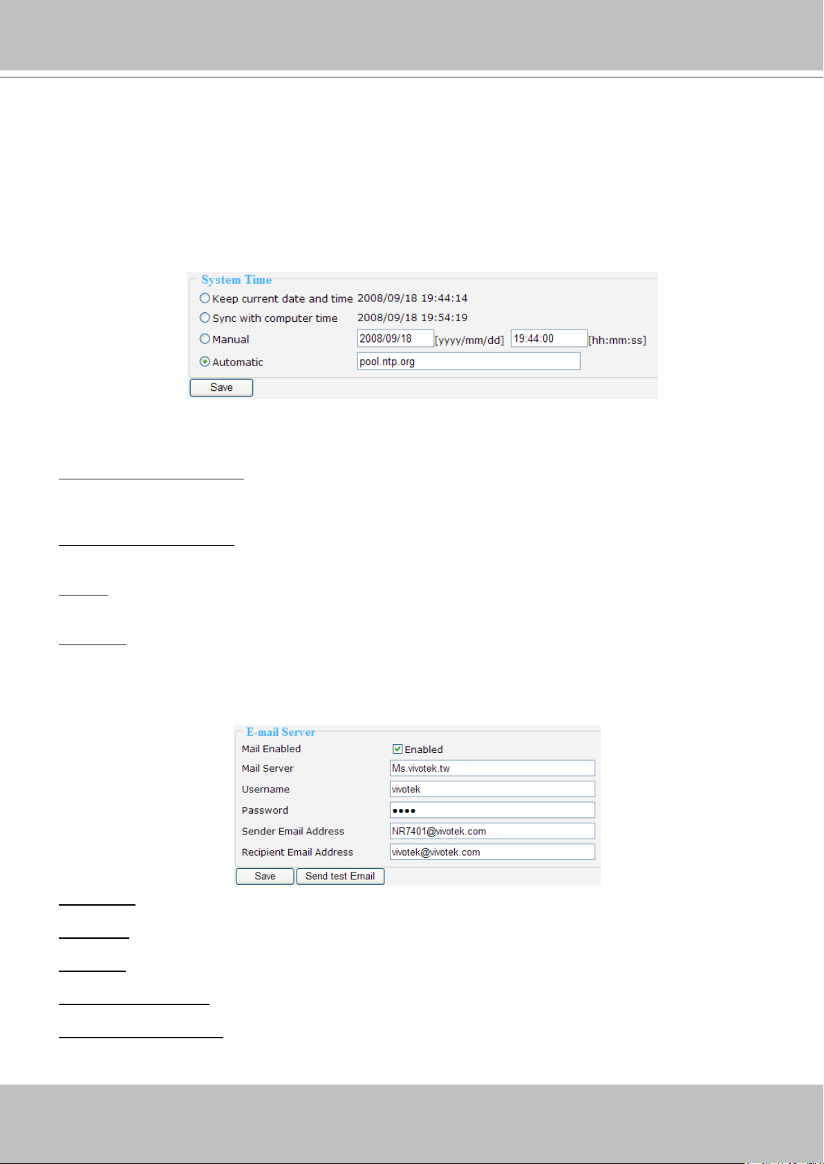
System Time
Select one of the following option to show the system time� It will show on the Status Panel on
the top of the webpage� Please refer to page 17 for detailed information�
Keep current date and time: Select this option to reserve the current date and time of the Network Video
Recorder� The Network Video Recorder’s internal real-time clock maintains the date and time even when
the power of the system is turned off�
Sync with computer time: Select this option to synchronize the date and time of the Network Video
Recorder with the local computer� The read-only date and time of the PC is displayed as updated�
Manual: The administrator can enter the date and time manually� Note that the date and time format are
[yyyy/mm/dd] and [hh:mm:ss]�
Automatic: The Network Time Protocol is a protocol serves synchronize computer clocks by periodically
querying an NTP Server� Assign the IP address or domain name of the time-server�
E-mail Server
Mail Server: Enter the domain name or IP address of the e-mail server�
Username: Enter the user name of the e-mail account�
Password: Enter the password of the e-mail account�
Sender Email Address: Enter the e-mail address of the sender�
Recipient Email Address: Enter the e-mail address of the recipient�
Check Enabled and click Save to enable the settings�
Page 36

VIVOTEK - A Leading Provider of Multimedia Communication Solutions
36 - User's Manual
FTP Server
FTP Server: Enter the domain name or IP address of the FTP server�
Username: Enter the login name of the FTP account�
Password: Enter the password of the FTP account�
Folder: Enter a folder to place the media le.
Check Enabled and click Save to enable the settings�
Digital Input
Here you can modify the Name of external digital inputs on the network video recorder�
Digital Output
Here you can modify the Name of external digital output on the network video recorder�
Page 37

VIVOTEK - A Leading Provider of Multimedia Communication Solutions
User's Manual - 37
Maintenance
This page allows Administrator to restore the Network Video Recorder to factory default, format
hard disk, and upgrade rmware version, etc.
System
Reboot: This feature allows you to turn off and then turn on the Network Video Recorder� It takes about
one ~ two minutes to complete the process� If the connection fails after rebooting, manually enter the IP
address of the Network Video Recorder in the address eld to resume the connection.
Restore Default Except Network Settings: This feature allows you to restore the Network Video Recorder
to factory default but retain the Network settings (WAN IP Address).
Restore Factory Default: This feature allows you to restore the Network Video Recorder to factory default�
Please note that the linked devices will be removed from the Device setting page, and all settings will be
erased� But the recorded data will remain on the History page�
The following message is displayed during the rebooting and restoring process�
Hard Disks
This column shows the information of your hard disk. For the rst time you install the hard disk, please
format it before recording� In addition, if you want to delete all recorded data, you can click Format Disk
to clean the hard disk� The following message is displayed during the formating process�
Firmware
This feature allows you to upgrade the firmware on your Network Video Recorder� Download a new
rmware le from VIVOTEK website. The le is in .upt le format.
It takes about five minutes to complete the process� Note that do not power off the Network Video
Recorder during the upgrade� The Network Video Recorder starts to upgrade and will reboot
automatically when the upgrade completes�
Page 38

VIVOTEK - A Leading Provider of Multimedia Communication Solutions
38 - User's Manual
Power POE Status HDD WAN LAN1 LAN2 LAN3 LAN4
USB socket
Status indicator
NR7401 Network Video Recorder
Backup
This page allows Administrator to backup the recorded data to an USB storage� Please format
the USB disk as EXT3 USB Storage le format.
NOTE
► After you insert the USB device, it will be displayed on the Hard disk information column as below.
Scheduled Backup
This column is for you to select what kind of recording data you want to backup� Check or uncheck the
Enabled blanks, and then select a Backup Time� Finally click Apply to start backup�
Manually Backup
This column is for you to backup all recorded data during a specic range of time. Select a desired time
and then click Backup to start the backup procedure�
Page 39

VIVOTEK - A Leading Provider of Multimedia Communication Solutions
User's Manual - 39
System log
This column displays the system’s log in chronological order� The system log is stored in the
Network Video Recorder’s buffer area and will be overwritten when reaching a certain amount�
Click Refresh, it will update the latest system log�
Page 40
VIVOTEK - A Leading Provider of Multimedia Communication Solutions
40 - User's Manual
Monitor
This page allows user to see the live view or playback recorded video from linked devices�
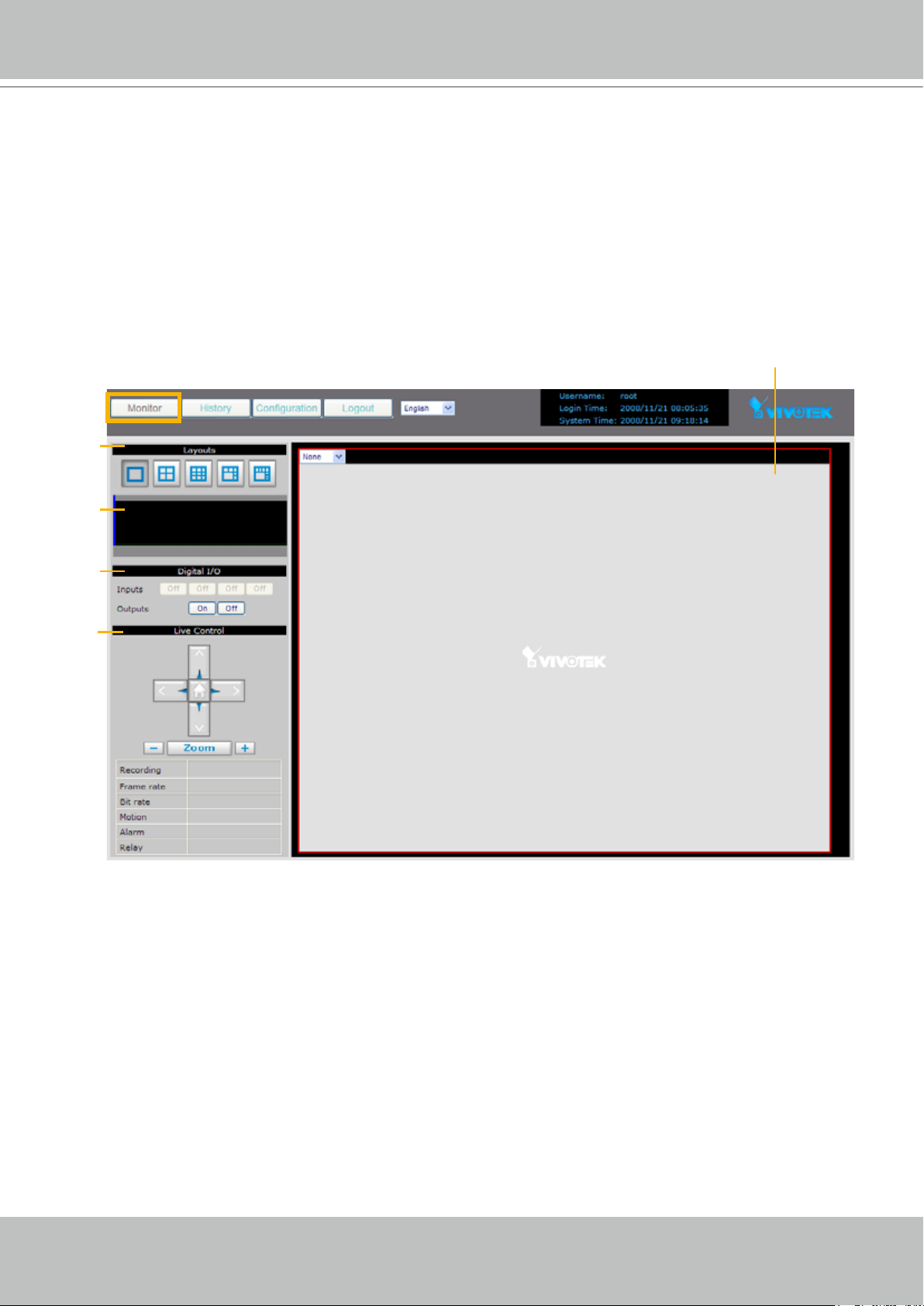
User Interface of Monitor Page
Click Monitor on the Main Menu, the user interface of Monitor page will be displayed�
■ Following is the Monitor page without linked device.
a
e
b
c
d
a. Layouts b. Time Bar and Histogram
c. Digital I/O Control Panel d. Live Control Panel
e. Video Cell
Page 41

VIVOTEK - A Leading Provider of Multimedia Communication Solutions
User's Manual - 41
■ Following pictures show the Monitor page with linked devices. For more information about
how to insert linked devices, please refer to Device on page 18�
Live viewing mode
Playback mode
Click on the Histogram to switch to playback mode� The Live Control Panel will turns into Playback Control
Panel as below� Click on the Playback Control Panel, it will switch to live viewing mode again�
Page 42
VIVOTEK - A Leading Provider of Multimedia Communication Solutions
42 - User's Manual
Functions of Monitor Page
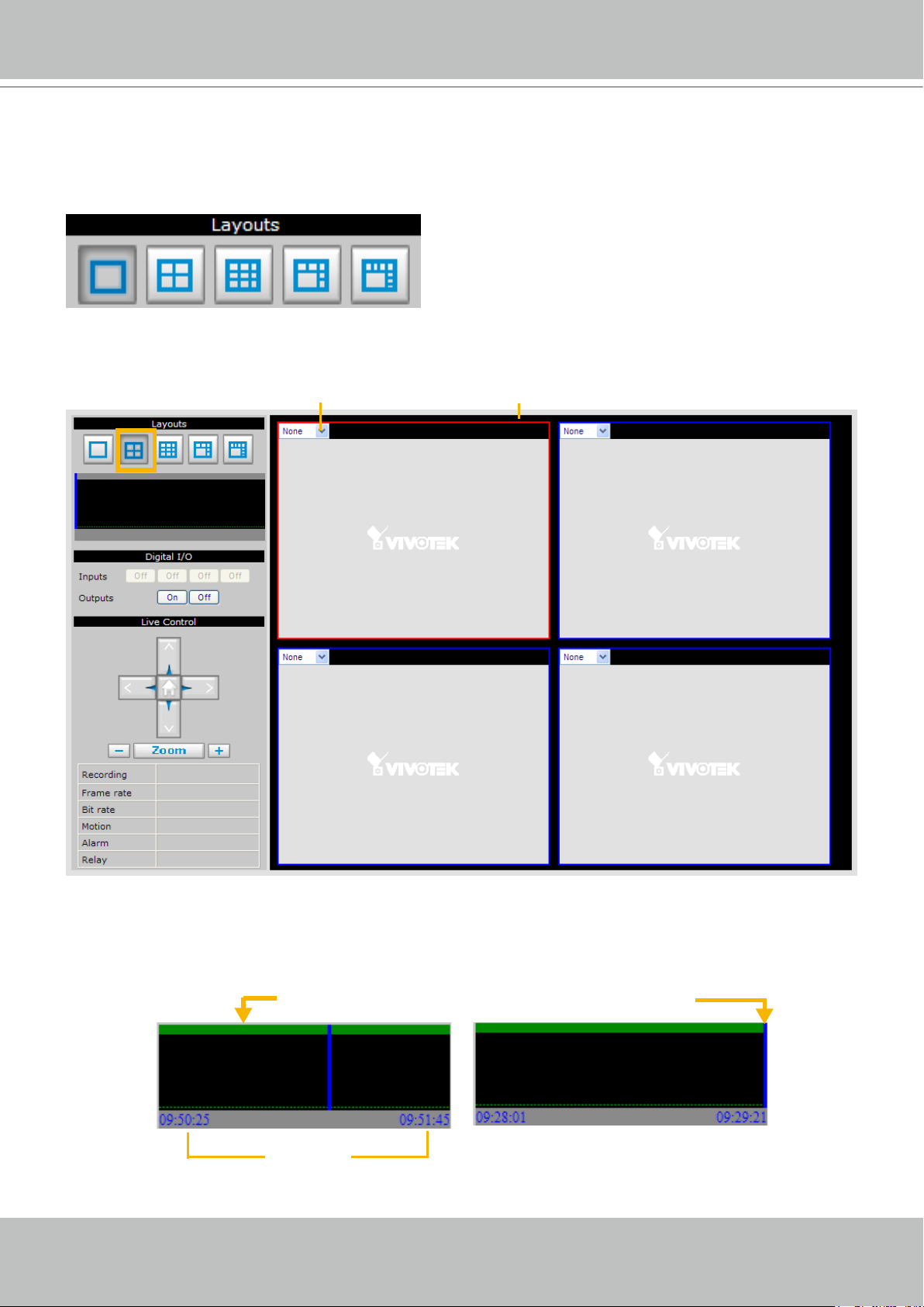
Layouts
Click the Layout buttons to change the viewing mode�
1x1 2x2 3x3 1+5 1+7
Following is an example of 4x4 layout� For each video cell, you can select a linked device on the dropdown list�
Drop-down list of Linked devices
The red frame represents the focused cell.
Time Bar and Histogram
In the Monitoring page, the Histogram only shows video clip for 80 seconds as below� The blue line is the
Time Bar�
Playback mode
80 seconds
Live Viewing mode
Page 43

VIVOTEK - A Leading Provider of Multimedia Communication Solutions
User's Manual - 43
Digital I/O
This column shows the DI status, and you can manually turn on/off the DO�
DI Status
DO Control
Live Control Panel
Only PTZ and speed dome network cameras will enable the PTZ control panel�
Recording Type: It will be different according to your settings on Recording Policy page and Device page�
Please refer to page 29 for detailed information� Following example shows that the current recording type
of the focused cell is Alarm recording�
up
home
rightleft
down
zoom out
Manual Recording
zoom in
Recording Type
Button
Status of motion
detection windows
DI status of the
linked device
DO control of the
linked device
Manual Recording Button: If you click Manual Recording Button on the Live Control Panel, the Recording
Type will turn into Manual recording� If you want to stop manual recording, click the button again�
Manual Recording Scheduled Recording
Page 44

VIVOTEK - A Leading Provider of Multimedia Communication Solutions
44 - User's Manual
Playback Control Panel
There are eight buttons for you to playback the recorded video clips (current 80 seconds)�
Play: To start or resume playback at normal speed�
Pause: To pause the playback� Click again to step forward a frame�
Stop: To stop video playback�
Live: To switch to live video�
Play rewind: To rewind recorded video� Click again to speed up (-4x, -16x, -64x)�
Play forward: To playback recorded video� Click again to speed up (4x, 16x, 64x)�
Previous: During playing mode, click this button to move to play the last video clip�
During paused mode, click this button to step back to display the last I-frame�
Next: During playing mode, click this button to move to play the next video clip�
During paused mode, click this button to step back to display the next I-frame�
Page 45

VIVOTEK - A Leading Provider of Multimedia Communication Solutions
User's Manual - 45
History
This page offers user a time-navigation interface to playback recorded video and browse the live
view from linked devices�
User Interface of History Page
Click History on the Main Menu, the user interface of History page will be displayed as below:
d
a
b
e
f
a. Time Picker b. Time Bar and Histogram
c. Recorded Video Clips d. Video Viewing Window
e. Playback Control Panel f. Recording Type
c
Page 46

VIVOTEK - A Leading Provider of Multimedia Communication Solutions
46 - User's Manual
Functions of History Page
Time Picker
Select Hard Disk: Select a storage device you want to review� If you have SD card, it will also show up
on the drop-down list�
Select Camera: Select a device you want to review�
Select Time: Select a period of time (Hour, Day, Week, or Month), which decides the length of histogram.
Start Time: The beginning of the selected period of time�
End Time: The end of the selected period of time�
: Click this button to go to the current period of time (current Hour, Day, Week, or Month).
: Click this button to go the last period of time (last Hour, Day, Week, or Month).
: Click this button to go the next period of time (next Hour, Day, Week, or Month).
: Manually input the time, and then click this button to go the selected period of time
(selected Hour, Day, Week, or Month).
Time Bar and Histogram / Recorded Video Clips
The recorded video clips in the selected period of time will show up on the histogram and be listed in the
recorded video clips window� In the following histogram, all recorded video clips are based on scheduled
recording (yellow bar)� The black Time Bar refers to the current time�
Scheduled recording
By default, the hard disk will save scheduled recording video for only one hour� The latest video clip will
erase the oldest one� For more information, please refer to Recording Policy on page 29�
Page 47

VIVOTEK - A Leading Provider of Multimedia Communication Solutions
User's Manual - 47
: The latest video clip, and still recording�
: The video with recorded audio� To enable the audio function, please go to Conguration > Device
to enable the Audio Compression setting of the Device�
: If you want to prevent a video clip from being erased by the latest video clip, select the
video clip and then click this button� A Protect Icon will show up�
: Select a video clip with Protect Icon and then click this button� Then the video clip becomes
unprotected�
: If you want to delete a video clip, select it and then click this button�
: If you want to export an AVI le of a video clip to your local computer, select it and then
click this button�
: Click this button to refresh the latest video clip�
Recording Type
The following color bar will show up on the histogram according to the recording type�
■ Grey bar (Empty): No recorded video.
■
Green bar (Cache): Temporary recording data� (prepare for pre/post-motion or pre/post-alarm recording)
■ Yellow bar (Scheduled): Record video according to recording schedule. For detailed conguration,
please refer to Schedule on page 27�
■ Orange bar (Motion): Record video when motion triggers on linked device.
■ Red bar (Alarm): Record video when alarm (external digital input) triggers on linked device or on the
network video recorder�
■ Blue bar (Manual): Record video when the user starts manual recording. Please refer to Manual
Recording on page 43 for detailed information�
Page 48

VIVOTEK - A Leading Provider of Multimedia Communication Solutions
48 - User's Manual
Example:
Following video clips list contains different kinds of recording type�
NOTE
► For the length of Scheduled Recording, Motion Recording, Alarm Recording, and Manual Recording,
please refer to Recording Type on page 30 for detailed conguration.
Page 49

VIVOTEK - A Leading Provider of Multimedia Communication Solutions
User's Manual - 49
■ There are two ways to playback recorded video clips:
1� Click a desired time on the histogram�
2� Click on a video clip, and then click on the playback control panel�
Page 50

VIVOTEK - A Leading Provider of Multimedia Communication Solutions
50 - User's Manual
pic01
pic02
pic03
Playback Status (Stopped)
Playback Status (Paused)
Playback Status (Live)
pic04
Playback Status (Playing)
Device Name
Video Viewing Window
This window playbacks the recorded videos� If you have not selected a video, the playback
status will be empty as pic01� Once you select a video clip to play, the video viewing window will
begin to playback the selected recorded video clips as pic02� If you click on the playback
control panel, the video viewing window will switch to the live video view as pic03� If you click
, the video will paused as pic04�
Playback Control Panel
There are eight buttons for you to playback the recorded video clips�
Play: To start or resume playback at normal speed�
Pause: To pause the playback� Click again to step forward a frame�
Stop: To stop video playback�
Live: To switch to live video�
Play rewind: To rewind recorded video� Click again to speed up (-4x, -16x, -64x)�
Play forward: To playback recorded video� Click again to speed up (4x, 16x, 64x)�
Previous: During playing mode, click this button to move to play the last video clip�
During paused mode, click this button to step back to display the last I-frame�
Next: During playing mode, click this button to move to play the next video clip�
During paused mode, click this button to step back to display the next I-frame�
Page 51

VIVOTEK - A Leading Provider of Multimedia Communication Solutions
User's Manual - 51
Appendix
System Overview
Alarm and Event Management
.Four D/I and one D/O for external sensor and alarm
.Event notification using SMTP
Security
.Multi-level user access with password protection
.IP address filtering
Users
.Camera live and playback viewing for up to 10 clients
Dimension
.360 mm (W) x 280 mm (D) x 43.8 mm (H)
Weight
.Net: 3100 g (without HDD)
LED Indicator
.System power, PoE ,status and hard disk indicators
.Network link indicators
Power
.100 ~ 240V AC
.Consumption
Max 21W without PoE camera
Max 35W with 4 PoE cameras
.802.3af compliant Power over Ethernet
Approvals
.CE, FCC, C-Tick, VCCI, UL, CB
Operating Environments
.Temperature: 0°~50° C (32°~122° F)
.Humidity: 20%~80% RH
Viewing System Requirements
.OS: Microsoft Windows 2000/XP/Vista
.Browser: Internet Explorer 6.x or above
Installation, Management, and Maintenance
.Installation Wizard 2
.Supports firmware upgrade
System
.CPU: Intel IXP425ABD
.Flash: 16 MB
.RAM: 128 MB
.Embedded OS: Linux
Video Channels
.Supports up to 9 channels
Hard Disk
.Supports SATA hard disk up to 1TB
Compatibility
.Supports VIVOTEK 6000- and 7000-series network cameras
Video Recording
.MJPEG and MPEG-4
Recording Throughput
.Total 12Mbps
Recording Policy
.Alarm recording
.Scheduled recording
.Manual recording
Connectors
.5 x Ethernet 10/100 BaseT, RJ45 (1 WAN and 4 LAN ports)
.USB socket for backup
.Terminal block: 4 digital input, 1 relay output, and 1 power
output with 12V max. 1A
Camera Management
.Auto or manual installation for VIVOTEK cameras
.Video and network configuration through NR7401
Pan/Tilt/Zoom Control
.Pan/tilt/zoom control of VIVOTEK cameras
History Playback
.Playback of recorded media with time navigations
Networking
.Protocols: IPv4, TCP/IP, HTTP, RTSP/RTP/RTCP, IGMP,
SMTP, FTP, DHCP, NTP, DNS, DDNS
Specifications
VIVOTEK Network Cameras
Internet
PC with
Web Browser
PC with
Web Browser
NR7401
Power POE Status HDD WAN LAN1 LAN2 LAN3 LAN4
NR7401 Network Video Recorder
USB Socket Status Indicator
RESET
LAN4 LAN3 LAN2 LAN1
WAN
12 3 4 5 6 7 8 9101112
Power Cord
Socket
Indented
Reset Button
General I/O
Terminal Block
Ethernet 10/100
RJ45 socket
Technical Specications
 Loading...