

Page 1
ND9322P
VIVOTEK - Built with Reliability
ND9424P
Network Video Recorder
User’s Manual
H.265/H.264 • 8/16 CH • 8/16 port PoE • 2 HDDs • ONVIF • Fisheye Dewarp •
HDMI/VGA Monitor Display • RAID0/1 • VIVOCloud • POS Integration
Rev. 1.6.1.11
Rev. 1.0
Rev. 1.3
User's Manual - 1
Page 2

VIVOTEK - Built with Reliability
Table of Contents
Chapter One Hardware Installation and Initial Conguration ...................................................................................... 8
Introducing the Network Video Recorder ............................................................................................................... 8
Special Features ............................................................................................................................................. 8
Safety .............................................................................................................................................................. 9
Chassis Dimensions .................................................................................................................................. 10
Physical Description ........................................................................................................................................... 10
LED Indicators ...................................................................................................................................................... 28
Power Up and Power Down ................................................................................................................................. 29
Section One Management over a Local Console ...................................................................................................... 30
Chapter Two Introduction to the Local Console Interface .......................................................................................... 30
2-1. How to Begin .......................................................................................................................................... 32
2-2. Operation on Camera View Cell ............................................................................................................. 38
2-2-1. PTZ Panel ........................................................................................................................................... 38
2-2-2. Digital zoom Panel .............................................................................................................................. 41
2-2-3. Play Recording Clips Panel ................................................................................................................ 42
2-2-4. DI/DO .................................................................................................................................................. 43
2-2-5. Others ................................................................................................................................................. 43
2-2-6. Right-click Commands ........................................................................................................................ 44
Chapter Three Conguation Using the Local Console .............................................................................................. 46
The Main Control Portal ....................................................................................................................................... 46
3-1. Layout .................................................................................................................................................... 46
3-2. DI/DO ..................................................................................................................................................... 46
3-3. Search recording clips ........................................................................................................................... 47
3-3-1. Basic Search ................................................................................................................................ 47
3-3-2. Alarm Search ............................................................................................................................... 51
3-3-3. Smart Search II ............................................................................................................................ 55
3-3-4. Smart VCA event search .............................................................................................................58
3-3-5. Storyboard ................................................................................................................................... 66
3-4. Export recordings ................................................................................................................................... 70
3-5. Settings .................................................................................................................................................. 72
3-5-1. Settings - Overview ...................................................................................................................... 72
3-5-2. Settings–Camera–Management .................................................................................................. 73
3-5-3. Settings–Camera–Recording....................................................................................................... 80
3-5-4. Settings–Camera–Recording....................................................................................................... 81
3-5-5. Settings–Camera–Media ............................................................................................................. 83
3-5-6. Settings - Camera - Image ........................................................................................................... 91
3-5-7. Settings–Camera–Motion Detection ............................................................................................ 93
3-5-8. Settings–Camera–PTZ settings ................................................................................................... 94
3-5-9. Settings–Alarm–Alarm ................................................................................................................. 96
3-5-10. Settings - Alarm - Email ........................................................................................................... 109
2 - User's Manual
Page 3

VIVOTEK - Built with Reliability
3-5-11. Settings–System–Information ..................................................................................................110
3-5-12. Settings–System–Maintenance ...............................................................................................111
3-5-13. Settings - System - Display ......................................................................................................112
3-5-14. Settings - System - UPS ..........................................................................................................113
3-5-15. Settings - System - Log ...........................................................................................................114
3-5-16. Settings - System - VIVOCloud service ...................................................................................116
3-5-17. Settings–User ..........................................................................................................................117
3-5-17. Settings–User-Login / Logout ..................................................................................................119
3-5-18. Settings–Storage .................................................................................................................... 120
Storage Volume RAID Levels ..................................................................................................................... 122
3-5-19. Settings - Storage - Scheduled backup .................................................................................. 127
3-5-20. Settings - Network .................................................................................................................. 130
Settings - Network - IP ........................................................................................................................ 130
Settings - DDNS .................................................................................................................................. 131
Settings–Service ................................................................................................................................. 132
3-6. POS .................................................................................................................................................... 136
3-7. Trend Micro IoT Security Service ........................................................................................................ 138
3-8. Information .......................................................................................................................................... 140
Section Two Management over a Web Console .................................................................................................... 141
Chapter Four Login and Getting Started ................................................................................................................ 142
4-1. Login .......................................................................................................................................................... 142
4-2. Graphical Layout and Screen Elements - Liveview .................................................................................... 146
4-2-1. Camera List Panel ........................................................................................................................... 147
4-2-2. Layout .............................................................................................................................................. 149
4-2-3. Layout contents ............................................................................................................................... 150
4-2-4. Logo & Menu ................................................................................................................................... 150
4-2-5. View Cell panel ................................................................................................................................ 151
Adding Cameras to View Cells ................................................................................................................... 151
4-2-6. PTZ panel ........................................................................................................................................ 160
4-2-7. Alarm panel ...................................................................................................................................... 162
4-3. Graphical Layout and Screen Elements - Search recording clips .............................................................. 166
4-3-1. Camera List Panel ........................................................................................................................... 167
4-3-2. Search Recording Clips Layout ....................................................................................................... 168
4-3-3. Logo & Menu ................................................................................................................................... 168
4-3-4. View Cells in Search Recording Clips .............................................................................................. 169
Search Recording Clips Control Panel ...................................................................................................... 170
4-3-5. Alarm Panel ..................................................................................................................................... 172
4-3-6. Calendar Panel ................................................................................................................................ 173
Chapter Five System Settings ................................................................................................................................ 174
Chapter Six Operation ............................................................................................................................................ 176
6-1. Liveview ..................................................................................................................................................... 176
6-1-1. Placing Cameras into the Layout ..................................................................................................... 176
6-1-2. PTZ and Other Screen Controls ...................................................................................................... 180
User's Manual - 3
Page 4
VIVOTEK - Built with Reliability
6-1-3. Audio ................................................................................................................................................. 183
6-1-4. Camera Properties and Controls ...................................................................................................... 184
6-1-5. Alarm Panel ...................................................................................................................................... 185
6-1-6. Layout view Control Buttons ............................................................................................................. 186
6-2. Search Recording Clips .............................................................................................................................. 187
6-2-1. Begin Playback and Search for Past Recordings ............................................................................. 187
6-2-2. Past Alarms and Bookmarks ............................................................................................................. 188
6-2-3. Synchronous Playback ..................................................................................................................... 189
6-2-4. Export media ..................................................................................................................................... 190
6-2-5. Time Search ...................................................................................................................................... 191
Safety and Compatibility .......................................................................................................................................... 193
NOTE:
1. The NVR is only to be connected to PoE networks without routing to outside plants.
2. For PoE connection, use only UL listed I.T.E. with PoE output.
NOTE:
Use the NVR only with a DC power supply that is UL listed, and limited power source (LPS)
certied. The power supply should bear the UL listed and LPS marks. The power supply should
also meet any safety and compliance requirements for the country of use.
1. La NVR ne doit être raccordée qu’à des réseaux PoE, sans routage vers des installations
extérieures.
2. Pour les raccordements PoE, utilisez uniquement un équipement de TI homologué UL, avec
une sortie PoE.
REMARQUE :
n’utilisez la NVR qu’avec un bloc d’alimentation CC homologué UL, ainsi qu’avec une
alimentation limitée (LPS) certiée. Le bloc d’alimentation doit porter les indications
d'homologation UL et LPS. Il doit également répondre aux exigences en matière de sécurité et
de conformité relatives au pays d’utilisation.
IMPORTANT:
The NVR also supports the VIVOCloud Retail app. Please refer to the VIVOCloud Retail app
User Guide for details.
4 - User's Manual
Page 5

VIVOTEK - Built with Reliability
Revision History
* Rev. 1.0: Initial release.
* Note that the Settings pages on the web console has been changed to that identical to the
local console.
* Rev. 1.1: (for rmware release rev. 2.6.x)
1. Supports connections to legacy cameras via RTSP. See page 74.
2. Supports Trend Micro IoT Security Service and related options.
3. Supports Remote connection with VAST server. See page 133.
4. Supports plug-in-free web sessions using Chrome and Firefox browsers. Currently
only 1 live view or 1 playback window is allowed per session.
* Rev. 1.2: for rmware rev. 3.0 and above.
- Supports Smart Search II for VCA (Video Contents Analysis) Smart Motion detection. The
occurrences of Smart Motion alerts can be quickly searched and retrieved from stored videos.
See page 62 for details.
- Supports 3D counting analysis and scheduled reports.
- Supports event monitoring & event search for Smart VCA, Smart 360, and Smart Motion
video analytics. See page 65. The triggers from VCA analytics detections can also be
congured into system alarms. When triggered, the related video clips can be exported.
- Cybersecurity management for cybersecurity alert, event log, (page 147) and event logging.
The NVR comes with TrendMicro security package, and can receive cyber attack information
from cameras. Also, these events can be collected by the VAST software.
- Added the protection for access to live view from unauthorized users. See page 127.
- Updated the description for the Alarm search function. See page 50.
* Rev. 1.3:
- Updaed the max. PoE port output for single port to 30W.
User's Manual - 5
Page 6
VIVOTEK - Built with Reliability
NOTE:
The following are the limitations for web access using the non-IE browsers:
1. Playback: fast forward, back forward, next frame buttons are not available.
2. Snapshot and Auto screen ratio not available on Safari.
3. Web browsers supported:
- Chrome v68.0.3440 and later ofcial version
- Firefox v61.02 and later ofcial version
4. OSes supported
- Windows
■ Windows 7, 64 bit
■ Windows 10
5. Minimum PC hardware requirements
1. CPU: Intel i5 4th generation and higher
2. RAM: 4GB and higher
Limitations on text entry length:
* User account: 64 alpha-numeric characters
* Account password: 64 alpha-numeric characters
* Path name: 256 alpha-numeric characters
* Supports all printable ASCII (0x21-0x7E) characters and space (ox20) for password.
!"#$%&\'()*+,-./0123456789:;<=>?@ABCDEFGHIJKLMNOPQRSTUVWXYZ[\]^_`abcdefghijklm
nopqrstuvwxyz{|}~
* IP domain name: host.xxx.yyy.zzz - 63 bytes; total: 253 bytes
* Email account: local@domain_name_part - local -63bytes
domain_name_part - 253 bytes.
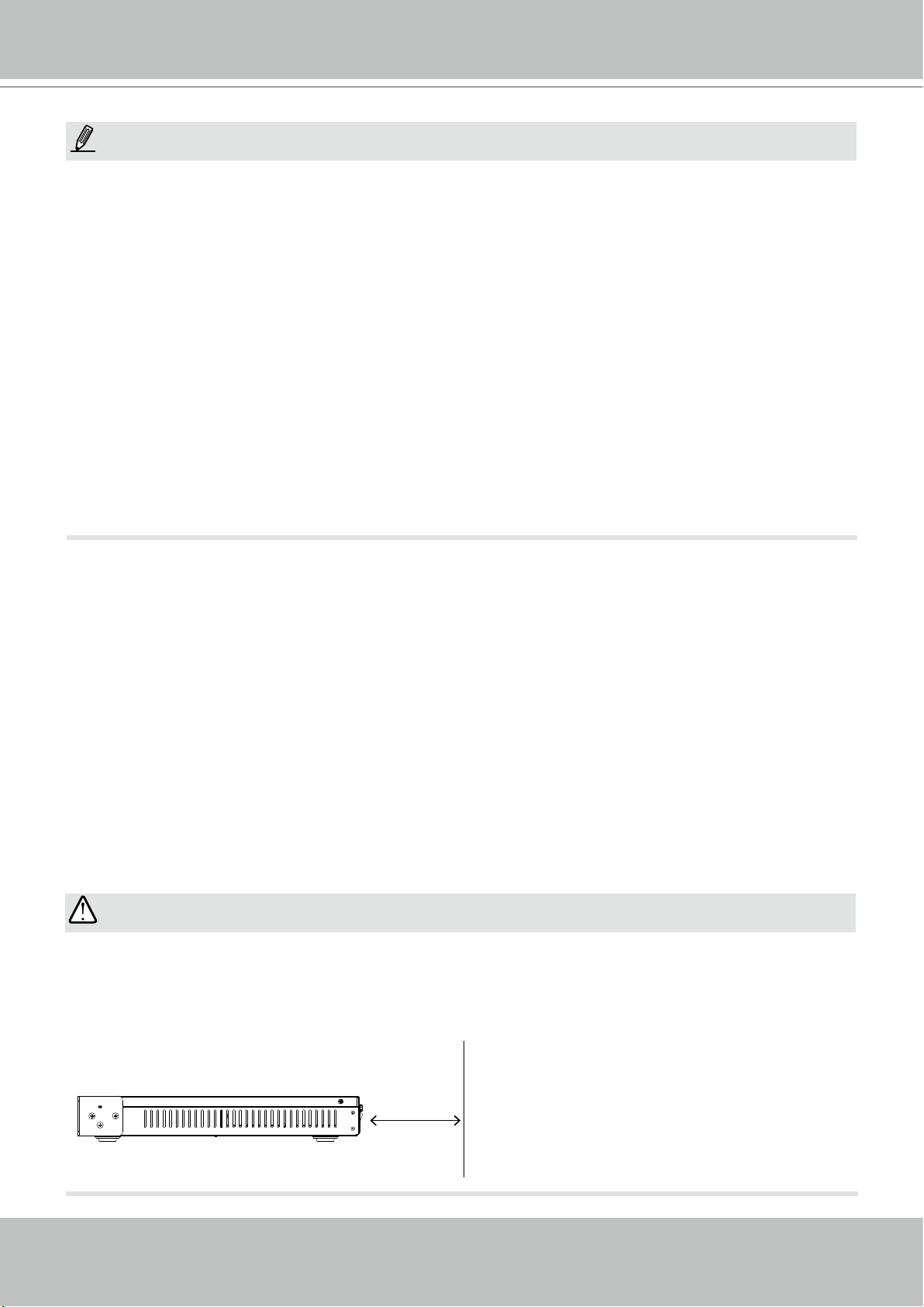
IMPORTANT:
It is important to leave a clearance of 25cm behind the chassis. The clearance is required to
ensure an adequate airow through the chassis to ventilate heat.
To ensure normal operation, maintain ambient airow. Do not block the airow around chassis
such as placing the system in a closed cabinet.
6 - User's Manual
25cm
Page 7
VIVOTEK - Built with Reliability
i
Read Before Use
The use of surveillance devices may be prohibited by law in your country. The Network Camera
is not only a high-performance web-ready camera but can also be part of a exible surveillance
system. It is the user’s responsibility to ensure that the operation of such devices is legal before
installing this unit for its intended use.
It is important to first verify that all contents received are complete according to the Package
Contents listed below. Take note of the warnings in the Quick Installation Guide before the
Network Camera is installed; then carefully read and follow the instructions in the Installation
chapter to avoid damage due to faulty assembly and installation. This also ensures the product is
used properly as intended.
The Network Camera is a network device and its use should be straightforward for those who
have basic networking knowledge. It is designed for various applications including video sharing,
general security/surveillance, etc. The Configuration chapter suggests ways to best utilize the
Network Camera and ensure proper operations. For creative and professional developers, the
URL Commands of the Network Camera section serves as a helpful reference to customizing
existing homepages or integrating with the current web server.
NOTE:
The operating system and management software are installed on a ash memory mounted on
the main board. Except for running the plug-ins for the onscreen control on a web console, there
is no need to install software.
Package Contents
■ ND9322P or ND9424P
■ Power cord
■ Quick Installation Guide
■ Mouse
■ Screws
Symbols and Statements in this Document
INFORMATION: provides important messages or advices that might help prevent inconvenient
or problem situations.
NOTE: Notices provide guidance or advices that are related to the functional integrity of the
machine.
Tips: Tips are useful information that helps enhance or facilitate an installation, function, or
process.
WARNING! or IMPORTANT: These statements indicate situations that can be dangerous or
hazardous to the machine or you.
Electrical Hazard: This statement appears when high voltage electrical hazards might occur
to an operator.
User's Manual - 7
Page 8

VIVOTEK - Built with Reliability
Chapter One Hardware Installation and
Initial Conguration
Introducing the Network Video Recorder
VIVOTEK’s ND9322P and ND9424P are H.265 Linux-based standalone NVRs with embedded
PoE. Equipped for up to 8-CH/16-CH network cameras, the NVRs support 8x or 16x 802.3 at/
af PoE ports. Both also display the PoE power information, providing for a more convenient and
smarter installation.
The NVR also supports remote and mobile access via VIVOCloud and iViewer apps for both
iOS and Android handheld devices. The VIVOCloud app provides instant push notification and
direct video playback functions when triggered by an alarm notification, providing users with a
flexible and intelligent NVR for seamless use in small to medium sized video surveillance applications.
With H.265 compression technology and embedded with 2 HDD’s providing up to 16TB of storage space, the NVR offers greater than 30% more recording capacity than H.264 systems. This
advancement provides users with more storage space for longer durations of video recording.
In addition, the RAID 0/1 configurations provide further data security in the rare event of a hard
drive failure.
For high-quality and detailed images, the NVR supports a maximum network camera resolution
of 4K,12-Megapixels. To intelligently manage bandwidth while maintaining this high-quality, the
“Auto Adaptive Stream” function will adjust the display resolution automatically for each different layout type. Furthermore, the NVR supports VIVOTEK’s fisheye network camera “Fisheye
Dewarp” function, which provides multiple de-warping modes in live view and playback, ensuring the correct angle of video view and detailed information for flexible usage. Lastly, to quickly
and intuitively find any target event, the NVR is equipped with the “Story-Board Search” function, which provides a glimpse of past recordings over an intuitive timeline.
The NVR supports HDMI and VGA local video output, so users can control the GUI OSD interface via mouse & keyboard, eliminating the need for a separate PC to search video or playback
from the NVR. Additionally, the intuitive and friendly VIVOTEK GUI design gives users a smoother control experience.
Special Features
● Runs on embedded Linux
● 1 x HDMI and 1 x VGA for local display
● 2 x HDD bay
● 1 x Gigabit RJ45 Ethernet port for uplink;
● 2 x USB Ports (1 USB 2.0 in front and 1 USB 3.0 in Back)
● Size: 360 mm (W) x 311 mm (D) x 44 mm (H). Weight: 3.16kg (w/o HDD).
● 8- or 16-CH Live View & 4-CH Synchronous Playback (web console)
● H.265 / H.264 / MJPEG
● Supports RAID0 and RAID1 volume configuration.
8 - User's Manual
Page 9

VIVOTEK - Built with Reliability
● PTZ Support
● Snapshot / Export Media
● Digital zoom Video Control
● VIVOCloud for effortless access from cell phones using a QR code
● Terminal block pins for DI/DO connection.
● Configuration Backup / Restore
● Compatible with VIVOTEK VAST Central Management Software*
● Integration with VIVOTEK Network Cameras
● VIVOTEK iViewer Support (iOS/Android cellphone/hand-held devices)
*The VIVOTEK VAST Central Management Software is not included in the package.
Safety
Connect the system to an earthed main power outlet.
Never open the housing of the power supply unit.
Install and operate the system only in a dry, weather-proof location.
Observe the following safety factors:
•
Is there visible damage to the system or power cord?
•
Is the system operating correctly?
•
Has the system been exposed to rain or moisture?
•
Has the system been in a long storage under harsh conditions or exposed to
unconforming stress?
The relevant electrical engineering regulations must be complied with at all times during
installation.
Ensure that all maintenance and repair work is handled by qualified personnel such as
electrical engineers or network specialists.
Read this manual before installing or operating the system. The documentation contains
important safety instructions about permitted uses.
The rated AC input is: 100-240V~ 3.5A, 60-50Hz; the max. consumption: 170W (ND9322P),
250W (ND9424P).
If a fault occurs, disconnect the power cord from the power supply.
Do not install the system close to heaters or other heat sources. Avoid locations with direct
sunlight.
All ventilation openings must not be blocked.
Use only the cables shipped with system or use appropriate cables that can withstand elec-
tromagnetic interference.
User's Manual - 9
Page 10
VIVOTEK - Built with Reliability
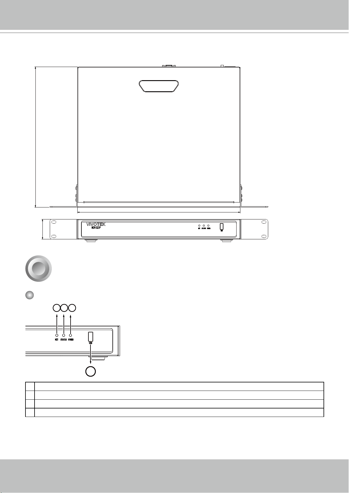
Chassis Dimensions
310.5
44
1
Physical Description
Front View
1
2
360
3
4
1 Network uplink status/activity LED
2 System status LED
3 System power status
4 USB 2.0 port
10 - User's Manual
Page 11
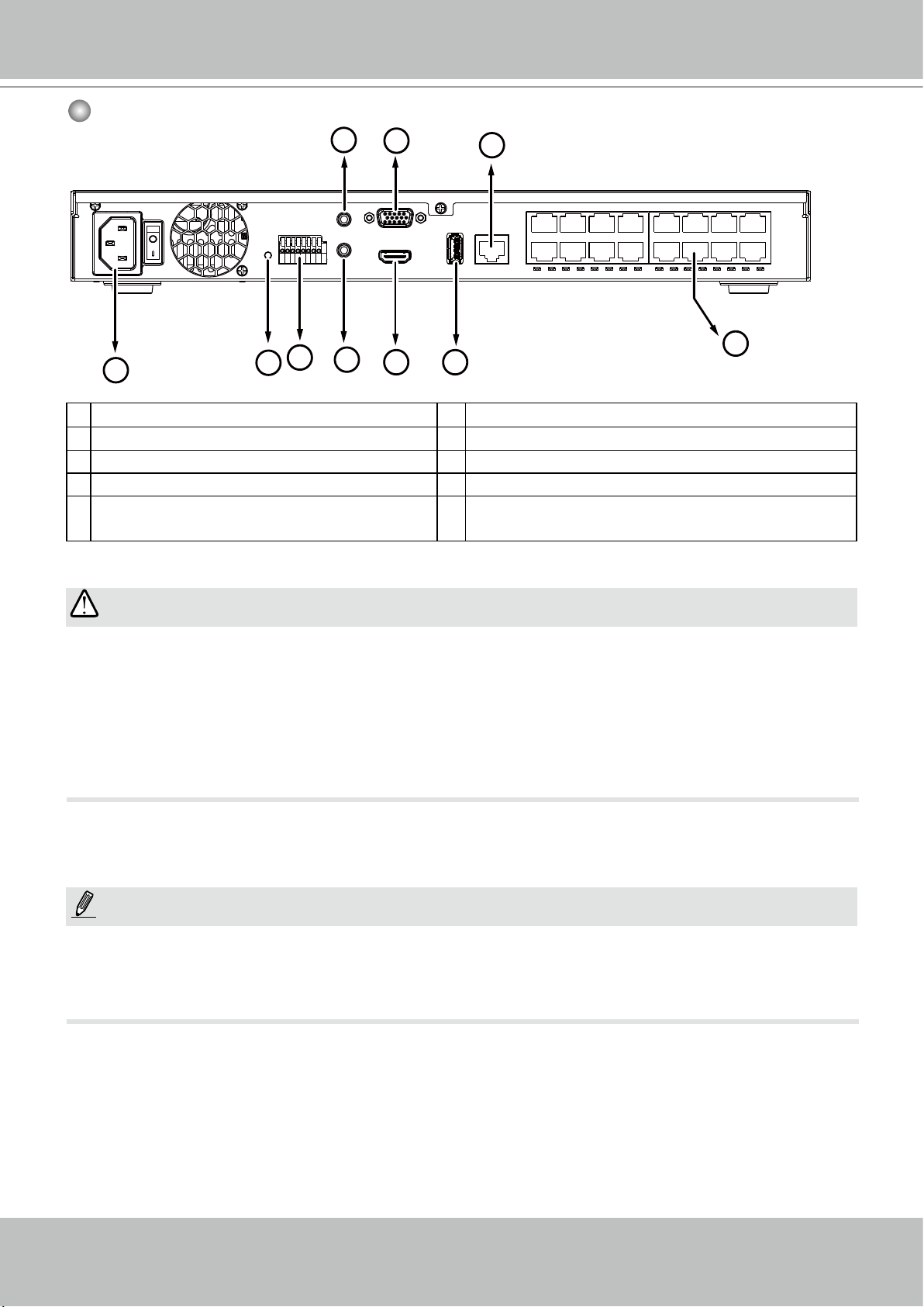
Rear View
VIVOTEK - Built with Reliability
6
7
2
1
8
10
1 PoE ports # 1 to #16 (ND9424P) 6 Audio OUT
2 RJ45 port - GbE uplink 7 VGA
3 HDMI 8 DI/DO terminal block
4 USB 3.0 port 9 Reset button
5 Audio IN 10 Power socket (110/240V AC), w/ a power
9
5
3
4
button
IMPORTANT:
The total power budget for the ND9322P’s 8 PoE ports is 120W. They can power 8x PoE class 3
(15.4W) cameras.
The total power budget for the ND9424P’s 16 PoE ports is 200W. Every 8 ports (#1 ~ #8 or #9 ~
#16) support 6x class 3 (15.4W) and 2x class 2 (7W) IP cameras.
The max. single port output can reach 30W, compliant with IEEE802.3at/af.
NOTE:
You can also use the Reset button to restore system defaults. Press and hold down the button
for longer than 5 seconds. The system should start restoring defaults.
User's Manual - 11
Page 12
VIVOTEK - Built with Reliability
2
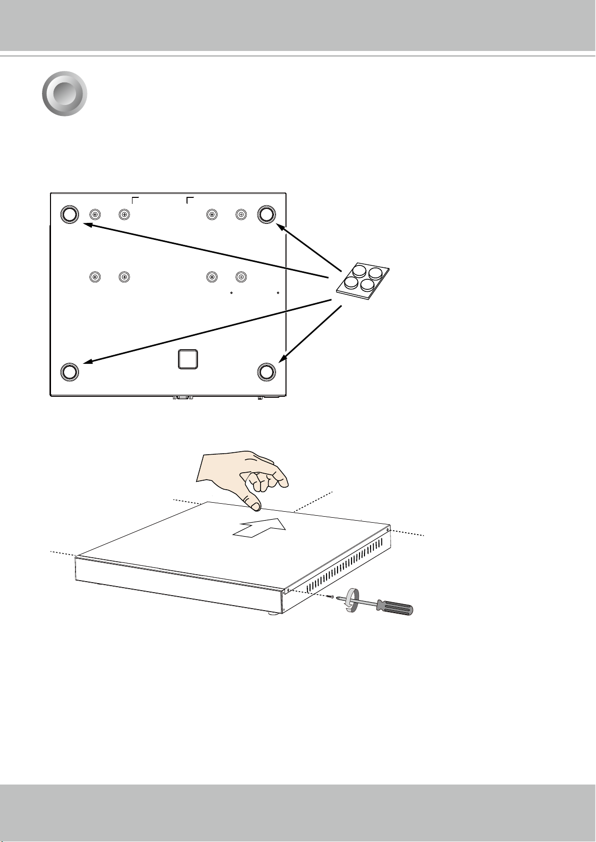
SATA hard disk(s) are user-supplied. The network video recorder can readily accommodate
most of the off-the-shelf SATA hard drives.
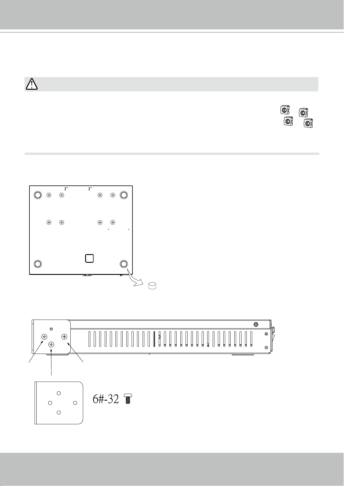
1. Attach 4 foot pads to the bottom of the enclosure.
Hardware Installation
2. Use a screwdriver to loosen the retention screws on the sides and the back of the chassis.
Slide the top cover back, and then remove the top cover.
12 - User's Manual
Page 13
VIVOTEK - Built with Reliability
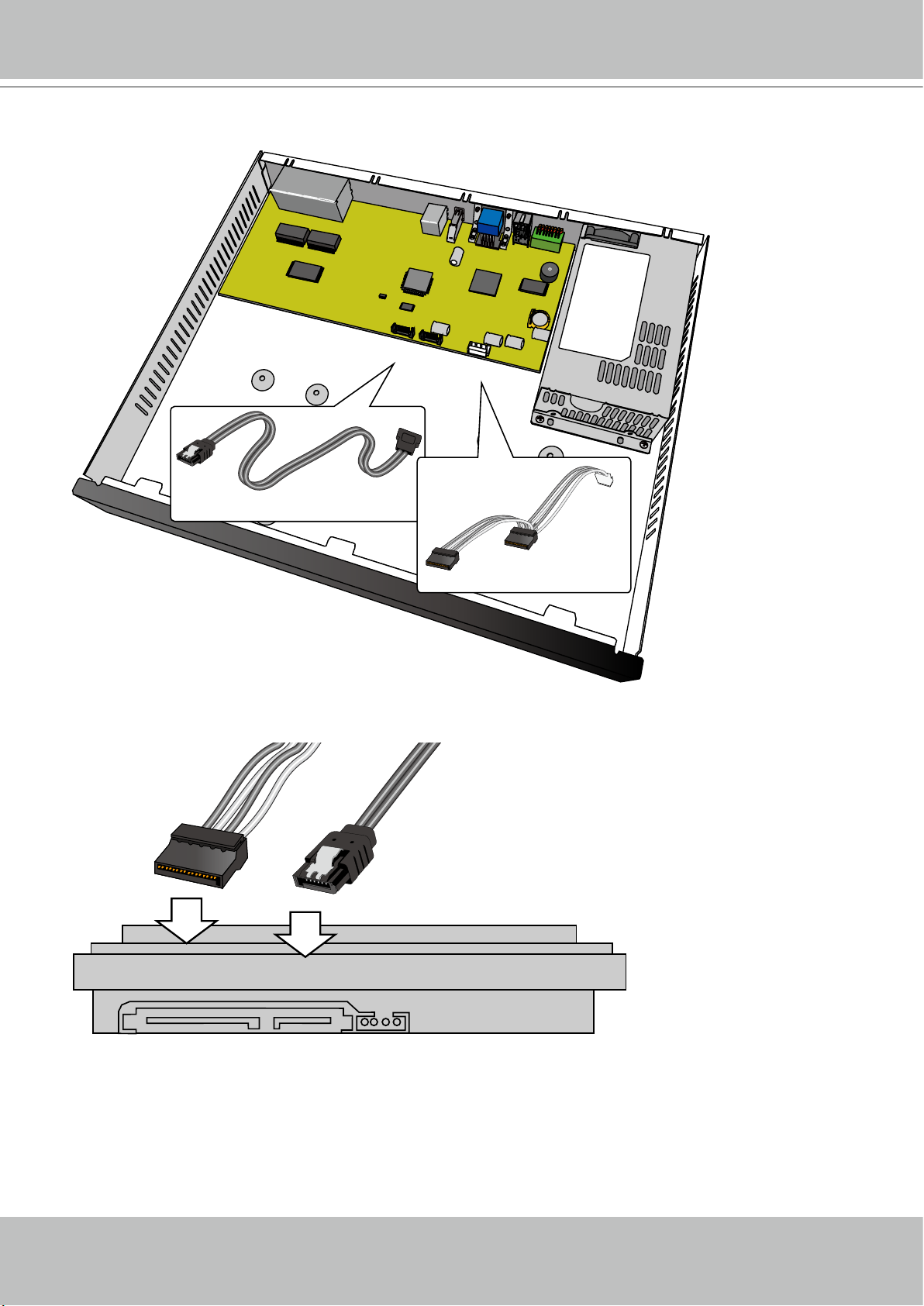
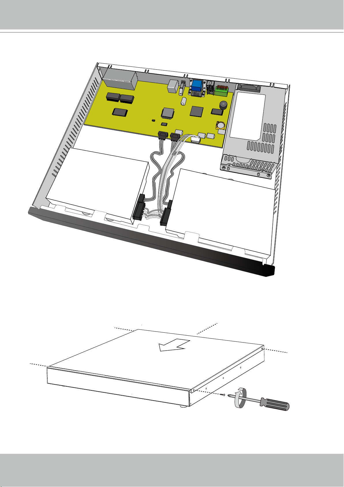
3. Connect SATA data and power cables to the main board.
SATA 2
SATA 1
J3
SATA Data x2
SATA Power x1
4. Connect the SATA power and SATA data cables to the hard disk drives.
SATA power SATA data
User's Manual - 13
Page 14
VIVOTEK - Built with Reliability
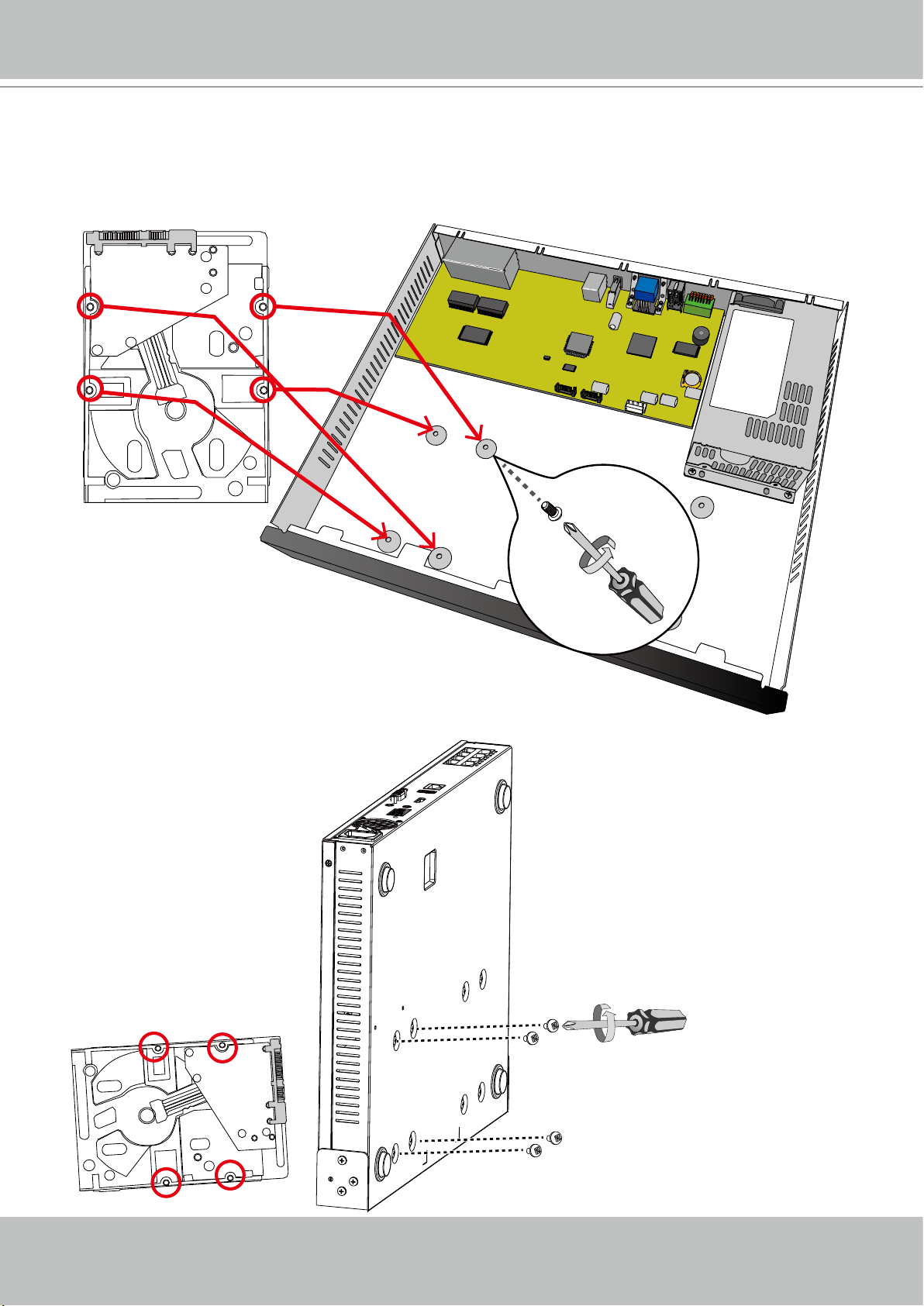
5. Install hard drives to the chassis. Note that the screws pass through the bottom of the chas-
sis and secure the hard drives using the mounting holes at the bottom of hard drives. When
installing hard drives, their label side should be facing up, and the connector side facing the
inside of the chassis.
SATA 2
SATA 1
J3
When matching the screws and mounting holes on hard
drives, you can let the enclosure stand on its side. Install
two hard drives from the bottom of the chassis.
14 - User's Manual
Page 15
VIVOTEK - Built with Reliability
6. Secure the hard disks to the mounting positions in the chassis with its label side facing up,
and the connectors facing the inside of the chassis. The sample drawing below shows the
positions.
SATA2
H.D.D.
7. When done, install the top cover.
SATA1
H.D.D.
User's Manual - 15
Page 16
VIVOTEK - Built with Reliability
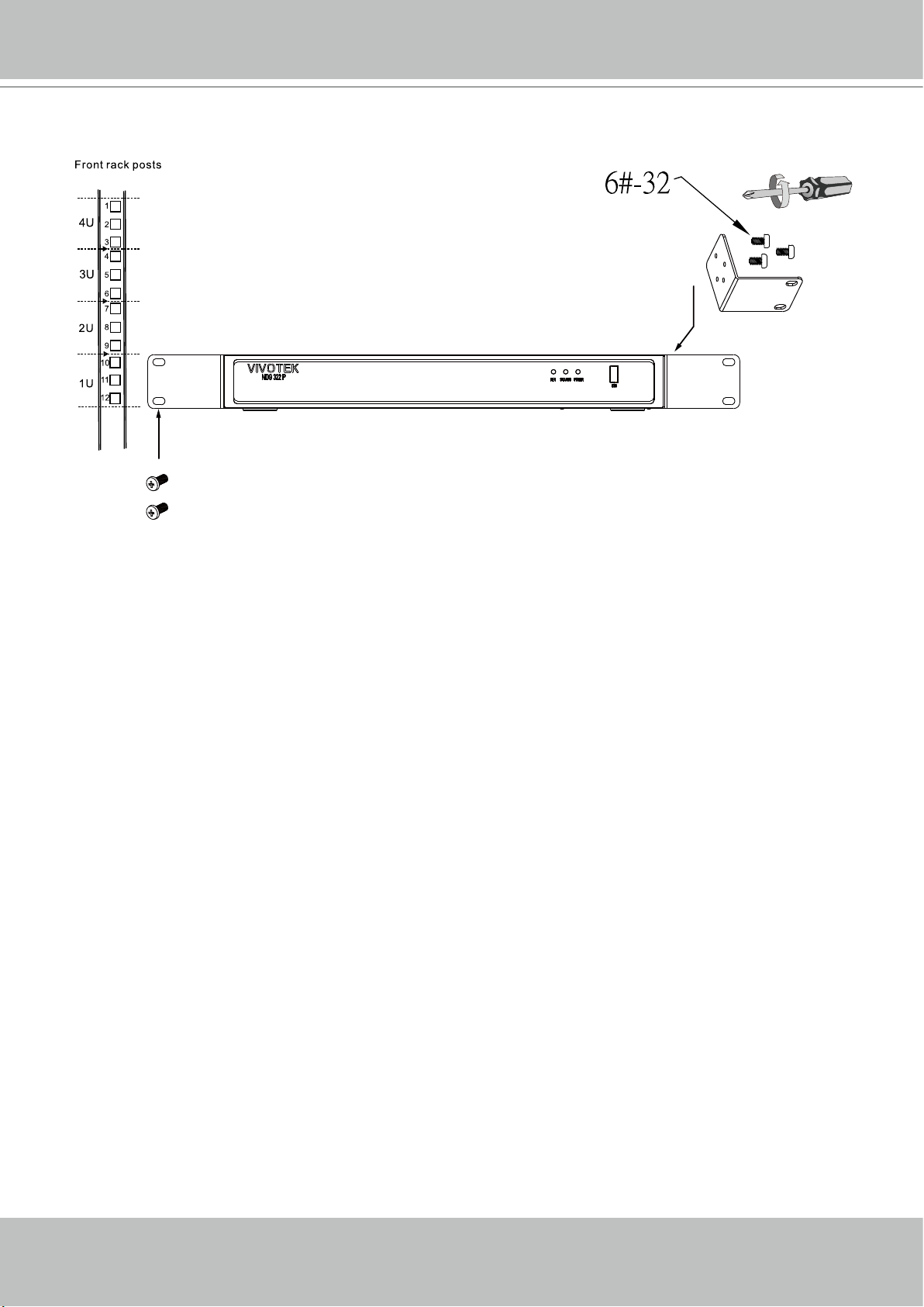
Rack-mounting (Optional, and the rack-mount brackets are separately
purchased)
IMPORTANT:
If you have either a round-holed or square-holed rack, install cage nuts or clip nuts to the
desired positions on the rack posts.
The instructions below are based on the installation to a 4-post equipment rack.
The slide rails apply to rack cabinet of a depth of 700 to 900mm. With 2 hard drives, the
chassis can weigh up to 4kg.
If you need to install the NVR system into a rack cabinet,
1. Remove the foot pads from underneath the chassis.
x4
2. Secure the brackets to the sides of the chassis by driving 3 included screws.
16 - User's Manual
Page 17
VIVOTEK - Built with Reliability
3. Secure the chassis to rack posts using 2 M6 screws on each side.
M6
User's Manual - 17
Page 18
VIVOTEK - Built with Reliability
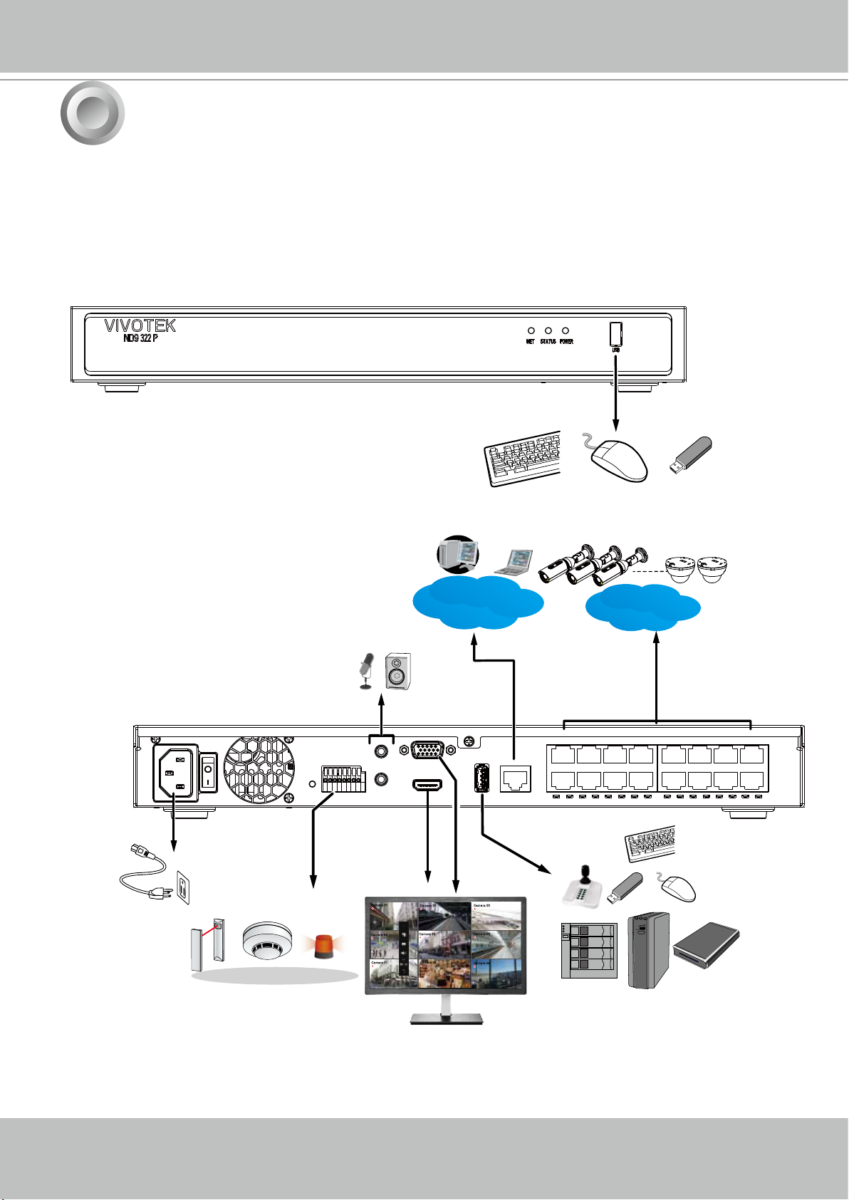
3
Interface Connections
1. Connect to a monitor using an HDMI cable. VGA is also supported.
2. Connect CAT5e or better-quality Ethernet cable to the GbE Ethernet ports.
3. Connect USB devices such as, mouse, keyboard, USB optical drive, or USB thumb drive (for-
matted in FAT format), joystick, or UPS.
4. Connect external devices, such as sensors, relays, or alarms to the terminal block.
5. Connect the system to the power mains.
AC100~240V
50/60Hz
Camera 01
Camera 04
Camera 07
LAN/WAN
Camera 02
Camera 05
Camera 08
LAN
#1 ~ 8 or 16
PoE
USB 3.0
Camera 03
Camera 06
Camera 09
18 - User's Manual
Page 19

VIVOTEK - Built with Reliability
NOTE:
1. Although the system supports MAC Binding, the system should be able to detect VIVOTEK's
cameras within the network regardless of the presence of a DHCP server. Ideally, cameras
and the NVR should reside in the same subnet. If a camera's IP is changed for some reasons,
the system should be able to detect its new IP.
2. Note on external storage enclosure via the USB 3.0 interface:
2-1. If external USB 3.0 storage is attached, a max. volume size of 16TB is supported. The
NVR supports the connection to a USB3.0 storage with a maximum of 5 disk drives. The
minimum storage size in the external storage is 64GB.
2-2. The external storage must be powered on rst before the NVR.
2-3. Hot-swapping is not supported. If the external storage is disconnected, recording will be
continued using the NVR's internal disk drives.
2-4. The storage conguration on the external storage is separately congured, e.g., RAID
conguration. The RAID volume on the external storage appears to the NVR as a single
large disk drive, and you should create a volume from it from the Storage conguration
page.
2-5. If the disk drives in the external storage are not congured into the NVR's storage
volumes, you can use them as the external backup devices. To do so, you should format
disk drives in the external storage in the FAT32 or NTFS format, and export the recorded
video on NVR to these disk drives.
2-6. Limitations:
• When you are exporting video to the disk drives in an external storage, you cannot
select the other disk drives to create a new volume.
• If the disk drives or volumes in the external storage is smaller than 1TB, you cannot
congure them as volumes for the NVR.
• The connection interface to external storage must comply with the USB 3.0
specications.
2-7. The RAID or volume conguration in the NVR does not extend to include devices in the
external storage.
User's Manual - 19
Page 20
VIVOTEK - Built with Reliability
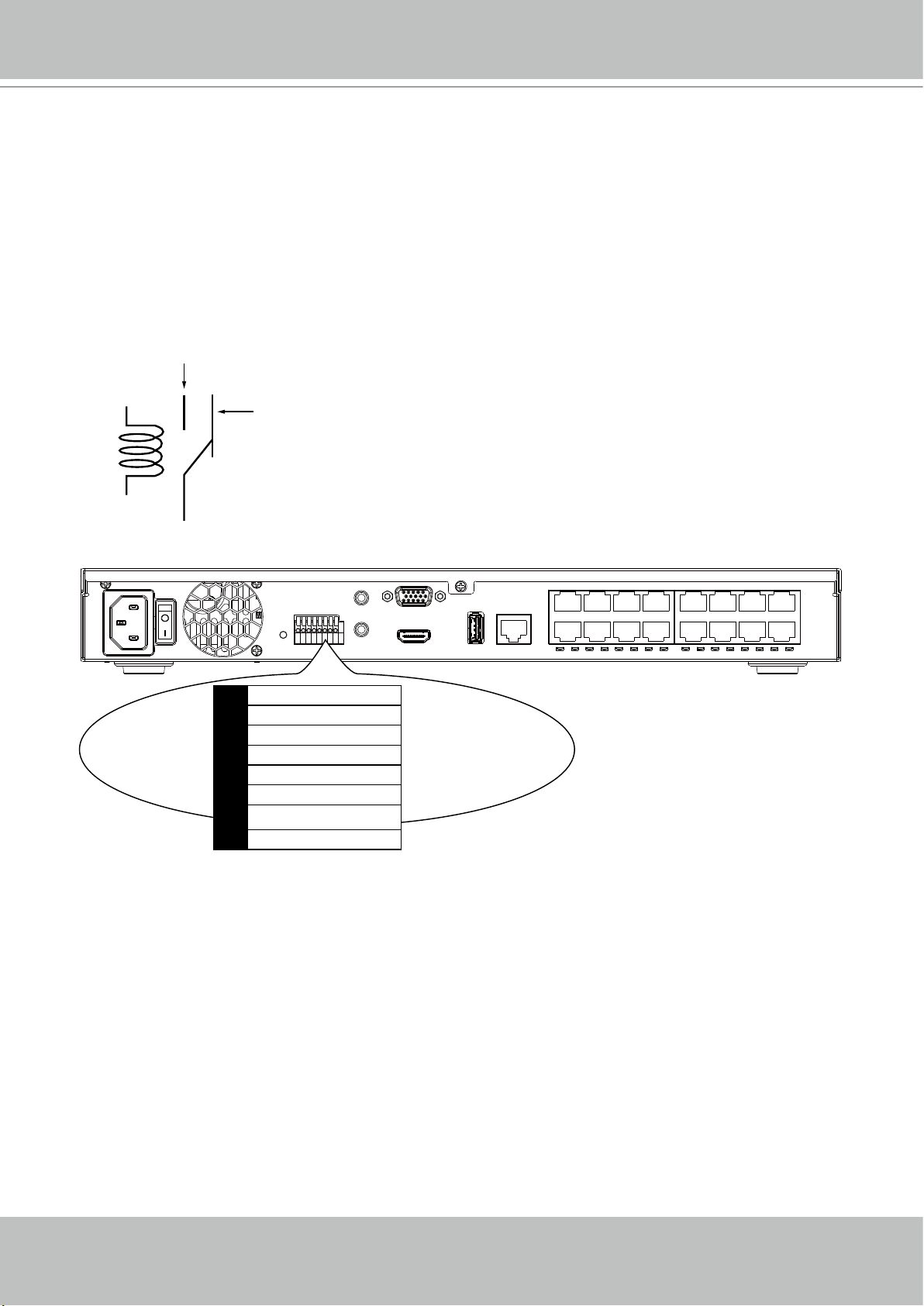
Terminal Block Connections
The terminal block pinouts is shown as follows:
The relay pins default status is set to Normally Open. Connect your relay or external devices’
signal wires to the system, the system will automatically detect the current signal status. You
can then trigger the external devices using the DI/DO panel on the live view.
You can also congure the system alarm setting for the system to automatically trigger a relay
pin on the occurrence of system events. See Alarm settings on page 96.
Normally Open
pin
Normally Closed
pin
Coil
Common pin
1 Relay_NO
2 Relay_COM
3 DI1
4 DI2
5 DI3
6 DI4
7 GND
8 GND
ssss
The GND are common ground for the DIs.
20 - User's Manual
Page 21
VIVOTEK - Built with Reliability
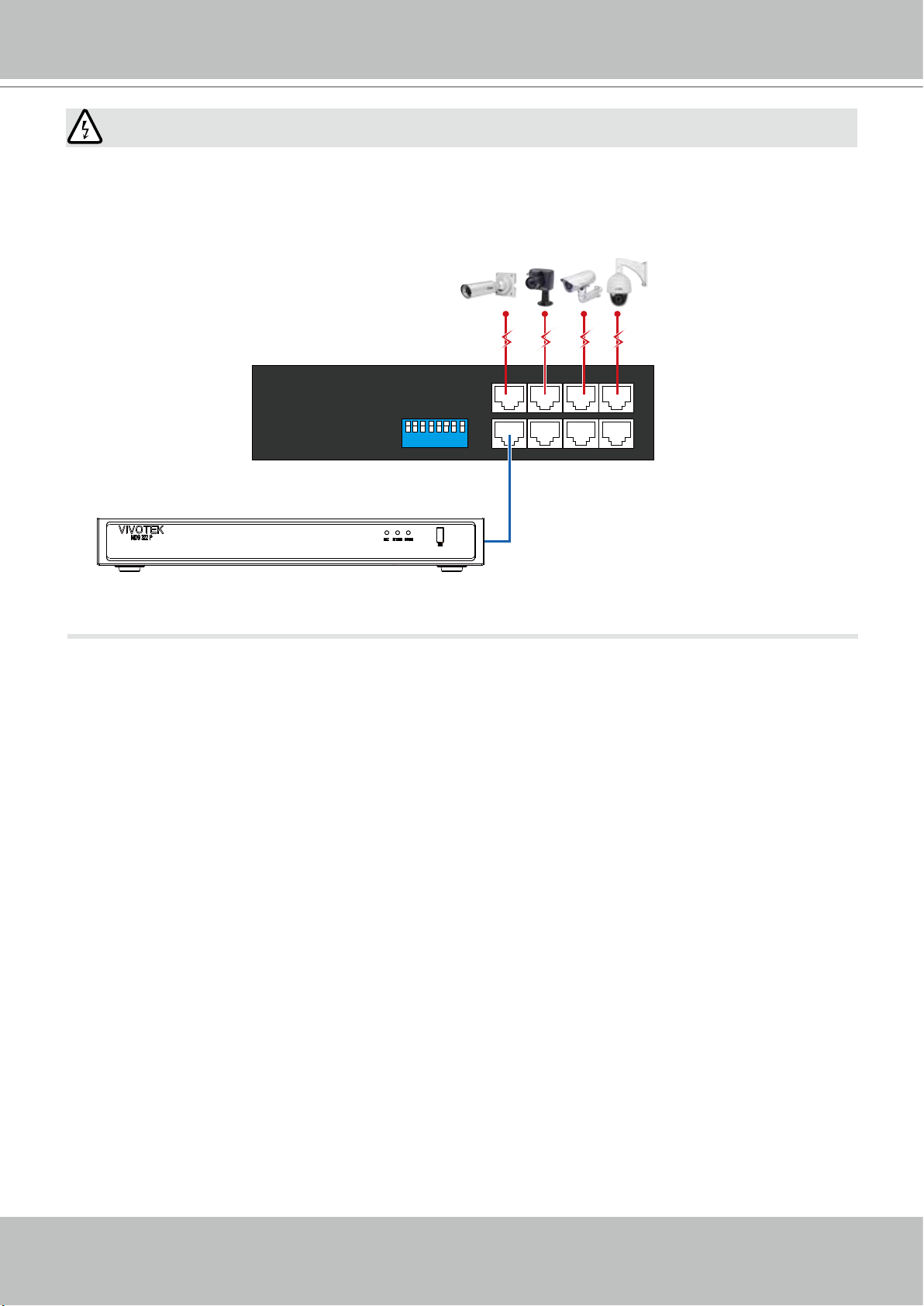
WARNING:
If you connect the NVR to a PoE port of the AW-FED series PoE switch, make sure you turn off
the PoE output on that specic port using the onboard DIP switch. Otherwise, the high power
output can damage the LAN port on NVR.
PoE cameras
AW-FED PoE switch
1 2 3 456 7 8
ON
PoE ON/OFF switch
NVR
User's Manual - 21
Page 22
VIVOTEK - Built with Reliability
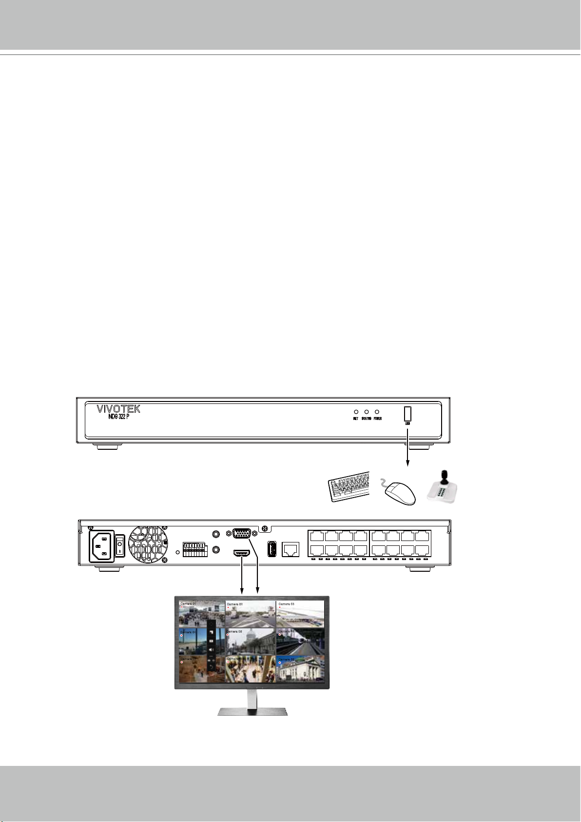
4
A local console requires the following:
1. A monitor is connected via an HDMI or VGA cable.
2. A mouse and/or a keyboard are connected to the system.
3. It is presumed that the system has not been congured yet.
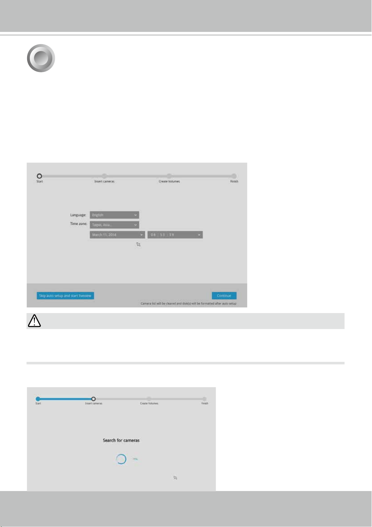
Follow the onscreen messages to complete the initial conguration:
1. Select the UI language, Time zone, and current date and time. Click on the Continue button
to proceed. Make sure you enter the correct date and time.
Initial Conguration - via a Local Console
IMPORTANT:
Except in the initial setup, changing system time can produce disruptions to the existing
recordings. Turning the current system time back to a time when video recording was taking
place can generate duplicate les. And those les may not be playable.
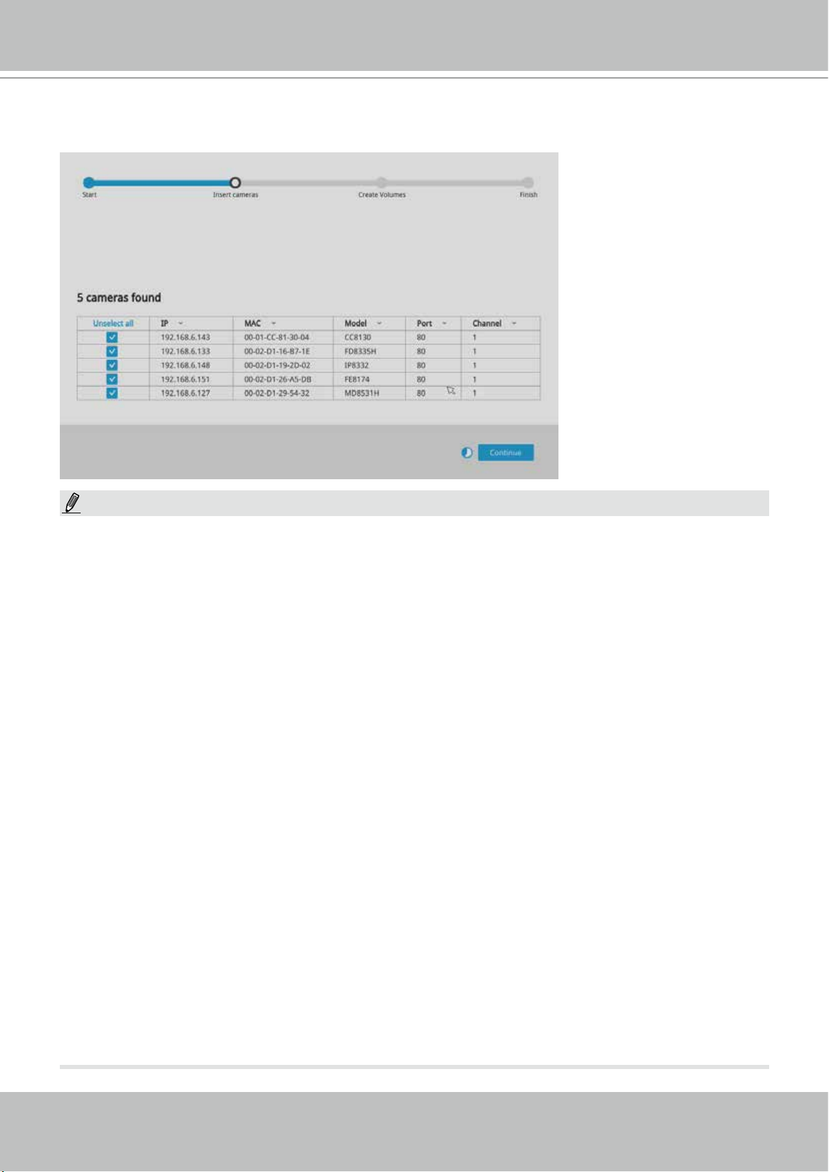
2. The system will then start to scan the local subnet for connected cameras.
22 - User's Manual
Page 23
VIVOTEK - Built with Reliability
3. All cameras detected on the network will be automatically selected. If necessary, deselect the
cameras you want to exclude from the conguration. Click Continue to proceed.
NOTE:
1. The maximum decoding bandwidth is
H.265
3840x2160@30fps 1 CH
1920x1080@120fps 4 CH
H.264
3840x2160@30fps 1 CH
1920x1080@120fps 4 CH
Recording throughput:
64Mbps (ND9322P); 96Mbps (ND9424P)
Pre-recording: 5 seconds (max. 10)
Post-recording: 20 seconds (max. 300)
When cameras are recruited into the conguration, their stream 1 is used as the recording
stream.
The resolution and fps (frame rate per second) of stream 1 may vary depending on the
specications of different cameras.
2. If there are less than 8 or 16 cameras, the Auto Setup will automatically move to the next
conguration step.
User's Manual - 23
Page 24
VIVOTEK - Built with Reliability
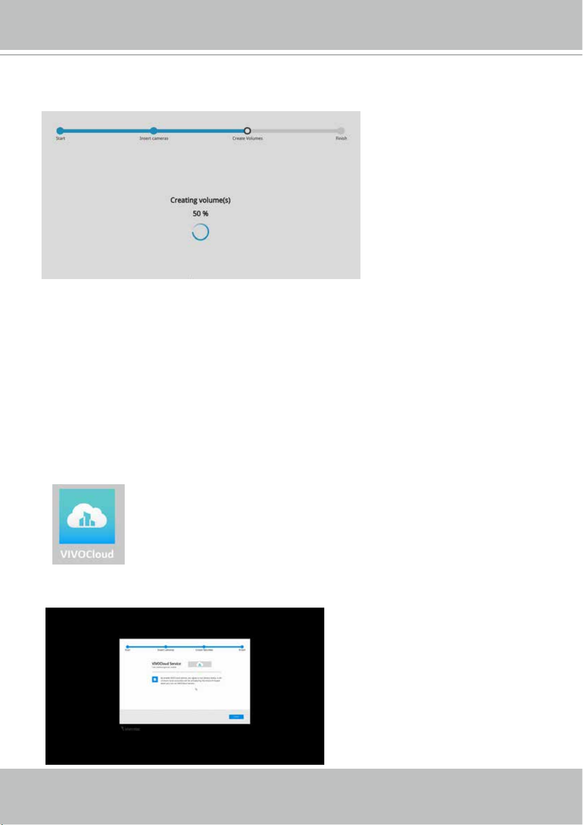
4. The system will automatically create volumes from the installed disk drives. The process will
take several minutes. Hard disks will be congured into single-disk volumes. You can delete
these volumes and then create RAID volumes in the Settings > Storage page.
5. An optional utility, VIVOCloud, is available through the Apple and Android App Stores. The
VIVOCloud works with a server hosted by VIVOTEK for bridging and tunneling video requests
between client devices and network cameras/CMS/NVR. The utility simplies and facilitates
network conguration for access across the Internet.
The prerequisites for using the VIVOCloud are as follows:
1. Download and install the VIVOCloud utility to your cell phone.
2. Both the NVR and your cell phone have access to the Internet.
With this utility, you do not need to congure IP port forwarding on router or set up a DDNS
address for the NVR. You do not even need to know the IP address of the NVR. The
VIVOCloud utility automatically manages the network parameters required for making the
connection. The VIVOCloud comes with viewing and playback interfaces very similar to those
in the iViewer utility.
To connect the NVR from a cell phone using the VIVOCloud:
5-1. Click on the VIVOCloud button on the wizard.
24 - User's Manual
Page 25
VIVOTEK - Built with Reliability
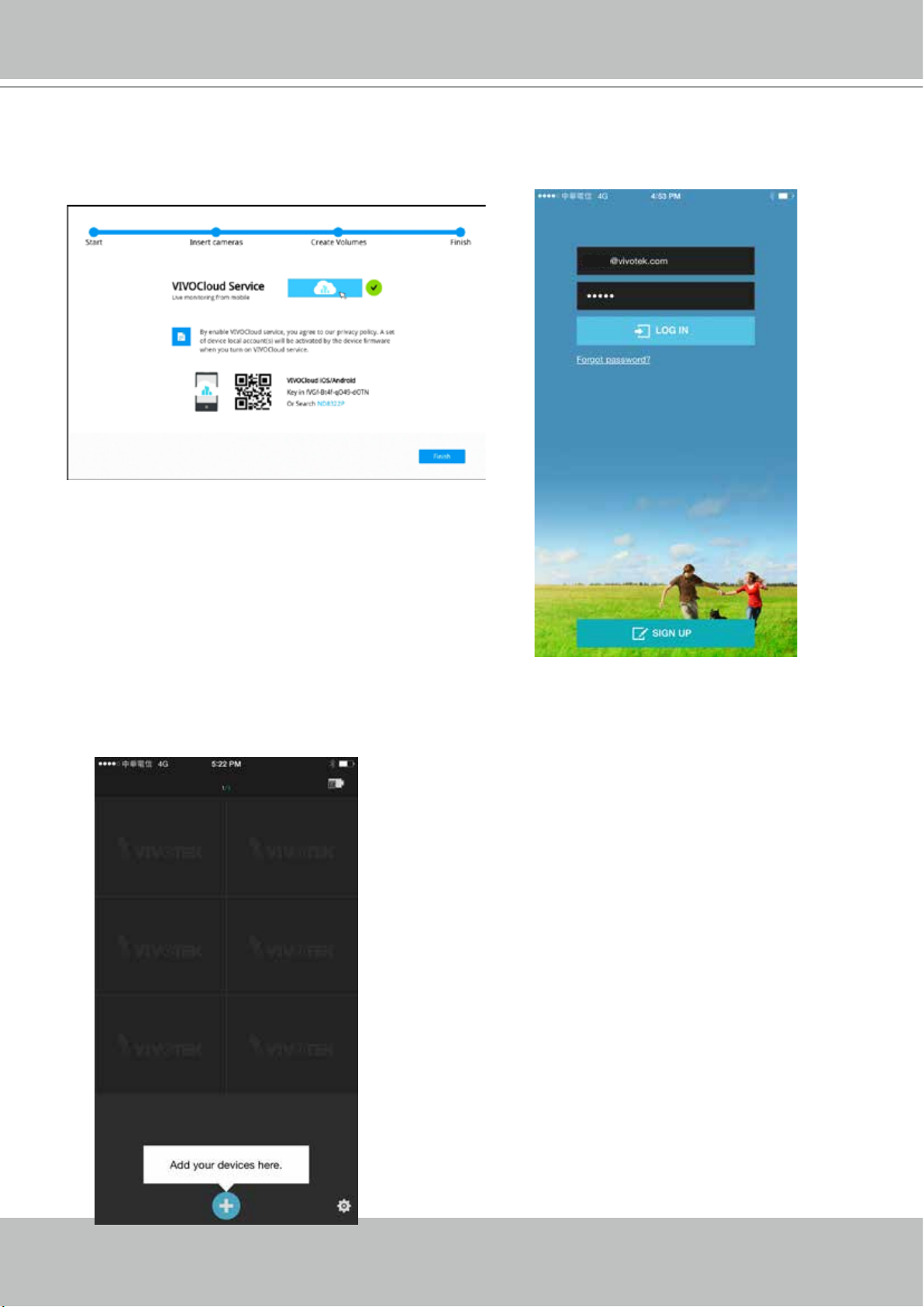
5-2. The QR code will be generated.
5-3. Open the QR code utility from your cell phone. If you already registered an account, tap
LOG IN. If not, tap SIGN UP to register an account from a VIVOTEK server.
User
The NVR also supports the VIVOCloud Retail app.
Please refer to the VIVOCloud Retail app User
Guide for details.
5-4. You can be defaulted to the Live view page. Tap the Add button below to add devices.
User's Manual - 25
Page 26
VIVOTEK - Built with Reliability
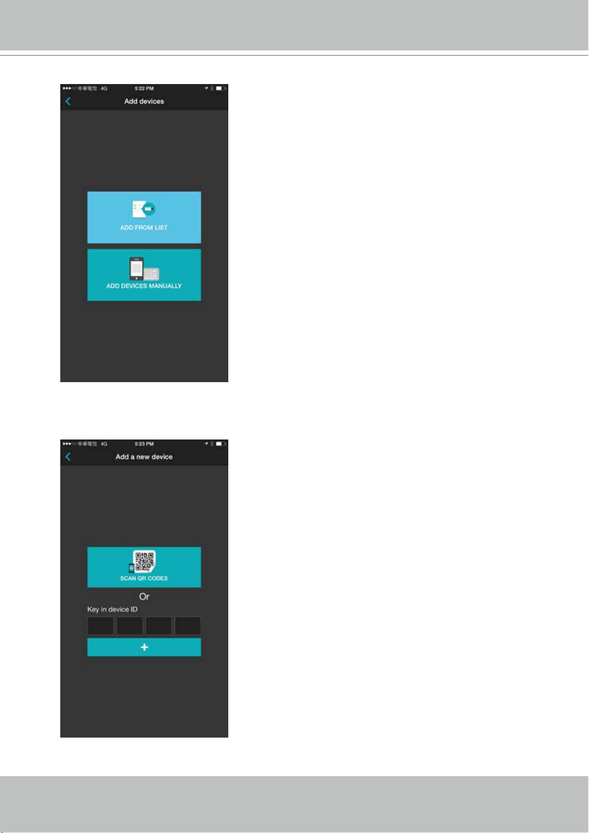
5-5. Tap the ADD DEVICES MANUALLY button.
5-6. You can then point your cell phone lens at the NVR screen (Step 5-3.) and use the
SCAN QR CODES function to establish the connection. You may also manually enter
the device ID.
26 - User's Manual
Page 27
VIVOTEK - Built with Reliability
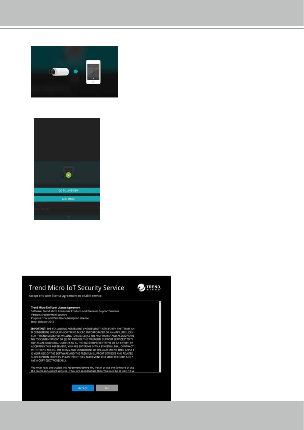
5-7. The process will take several seconds to complete.
5-8. The NVR and the cameras under it will be ready for access.
6. Click the Done button.
7. Read the Trend Micro IoT Security Service licencse statement. Click the Accept button when
done.
The LiveClient screen will display, and, by default, the recording from the selected cameras
will immediately take place.
User's Manual - 27
Page 28
VIVOTEK - Built with Reliability
5
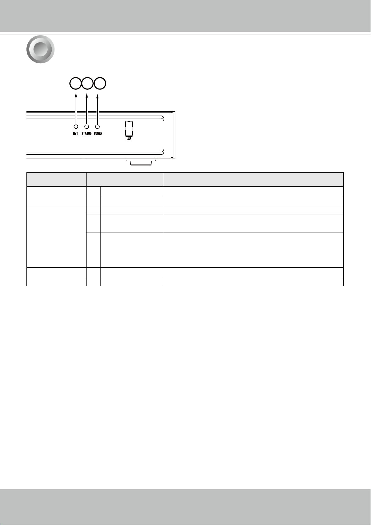
LED Indicators
1
2
3
Name Behavior Denitions
1. NET LED 1 Blinking Orange Data is being transmitted or received.
2 OFF The Ethernet uplink is disconnected.
2. Status LED 1 Constant Green System ready.
2 Blinking Green
every 1 second
3 Constant Red 1. S.M.A.R.T.-related disk errors,
3. Power LED 1 Solid Green The NVR is powered on.
2 OFF The NVR is powered off.
Updating rmware or device pack.
2. A congured H.D.D. is missing,
3. H.D.D. is full. Buzzer will also be sounded. When
buzzer is turned off, LED will return normal.
28 - User's Manual
Page 29
VIVOTEK - Built with Reliability
6
To power up and power down,
On the initial conguration:
1. Connect the power cord between the system and power outlet.
2. Turn on the system using the power button on the back of chassis.
After the initial connection,
Use the power down button on the lower right corner of the Settings page. The system
should start ushing the cached contents in system memory and gracefully shut down. You
should then ip the power switch button on the back of chassis to completely shut down the
system.
Press the Reset button for longer than 5 seconds can restore system defaults.
1. No storage system is completely fail-safe. Damage to data might occur due to le system
corruption, operating system malfunction, virus infection, HDD component failures, and so on.
Therefore, it is highly recommended to regularly back up your data, and VIVOTEK disclaims
responsibilities of data loss or recovery.
Power Up and Power Down
WARNING:
2. Always power off the system using the power button on the back of chassis. The system is
powered off when you observe that all LEDs go off. Do not disconnect the power cord while
the system is still operating. Doing so will result in data inconsistencies. The normal power-off
procedure allows cached data to be written to disks.
NOTE:
If system buzzer is sounded, move your mouse cursor to reveal the main screen portal, and
then click on the Stop buzzer button.
Serious system faults, such as a missing volume, can trigger the system buzzer. Verify the
cause of system fault and turn off the buzzer.
User's Manual - 29
Page 30
VIVOTEK - Built with Reliability
Section One
Management over a
Local Console
Chapter Two
Introduction to the Local Console Interface
30 - User's Manual
Camera 01
Camera 04
Camera 07
Camera 02
Camera 05
Camera 08
Camera 03
Camera 06
Camera 09
Page 31

VIVOTEK - Built with Reliability
Virtual keypad
By default, a live view appears on an HDMI monitor. The interface architecture of the local
console is illustrated as follows:
LiveView Main screen
Main control portals
PTZ
Digital zoom
Smart search II
Play recording clip
Audio
DI/DO
Snapshot | Manual
recording
Deselect camera
Config. portal
Camera portal
When a view cell is selected.
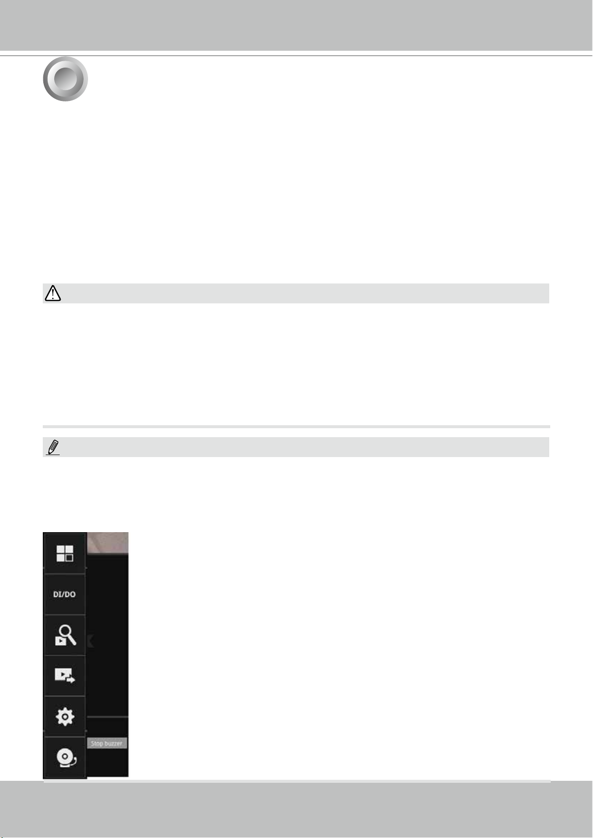
Layout
DI/DO
Search recording clip
Export recordings
Settings
Stop buzzer
Overview (camera connection & storage)
Camera
Alarm
System
User
Storage
Network
POS
Information
Time Search panel
Alarm search
Smart search II
Smart VCA event search
POS search
Storyboard
Management
Recording
Media
Alarm
Email
Information
Maintenance
Display
UPS
Logs
VIVOCloud service
User
Login / Logout
Storage
Scheduled backup
IP
DDNS
Services
POS
TrendMicro IoT Security
service
Image
Motion detection
PTZ settings
After you nish conguring using a Camera portal, click again on the camera view cell to reveal
the main control portals.
IMPORTANT:
Due to the limitation of system resources, the sheye dewarp (1R, 1P, 1O3R, 1O8R modes) can
only take place on one view cell, for one sheye camera.
For the Export recordings function, refer to page 70.
User's Manual - 31
Page 32

VIVOTEK - Built with Reliability
2-1. How to Begin
1. How to access the Conguration Portal?
Make sure a mouse is attached to your NVR. Move your mouse cursor, and the Conguration
Portal will appear on screen. For all the congurable options available through this portal,
please refer to Chapter 3 on page 46.
You can also hide these portal toolbar. Right-click on the LiveView screen to
display the option.
2. How to access the Camera Portal?
Single click to select a view cell, the Camera Portal will appear. The system automatically
detects the characteristics of an individual camera when you select a view cell.
This portal appears with a camera that supports mechanical PTZ.
This portal appears with a camera that does not support mechanical PTZ.
Tips:
Here are some operation steps using the tool bar:
1. Single-click to select a view cell and bring out the tool bar.
2. Double-click to expand a view cell to the full view.
3. Double-click again to shrink the view cell to the original size.
32 - User's Manual
Page 33

VIVOTEK - Built with Reliability
Home
PTZ control panel for ordinary PTZ type
PTZ control panel for joystick type PTZ
Move
speed config
Pan/Tilt
controller
Focus far
Focus near
Patrol button
Zoom
controller
Preset
points
posion
PTZ presets: If your PTZ cameras have preset locations, click on the button to unfold the preset
menu. Click on any of the preset locations to move to the area of your interest.
Pan/Tilt controller: Pull the inner circle to the direction you prefer. Release the mouse button to
stop moving.
Zoom controller: The zoom controller buttons only apply to cameras that come with an optical
zoom module, such as a speed dome camera.
Focus controller: The focus controller buttons apply to cameras that come with focus control
over its lens module, such as a speed dome camera.
3. How to retrieve and access recorded videos?
3-1. One is to access the video clips taken within 2 hours. Left-click to select a view cell, and
then click on the Recording clips button.
Select a time value by a single click. You will be prompted for User
name and Password, enter admin and admin (the default user name
and password), and then click Login.
User's Manual - 33
Page 34

VIVOTEK - Built with Reliability
The Playback window will prompt, and a playback begins from the point in time you selected,
e.g., 30 seconds ago. This function allows you to quickly review what has just happened.
03 - Camera 03
2016.05.16
17:15:41
1x
10:32:56
2015.09.22 1x
01 - Camera 01
2016.05.16
17:15:41
1x
3-2. Another way to access past videos is to open the Search recording clips window. Move
your mouse cursor to display the Conguration Portal (without selecting any view cell).
Click on the Search recording clips button. Please refer to page 47 for more information
about the search functions.
You will be prompted for User name and Password, enter admin
and admin (the default user name and password) and click Login.
It is highly recommended to change the password after you log in.
34 - User's Manual
Page 35

VIVOTEK - Built with Reliability
4. How to recieve system alarm?
Please refer to page 96 for how to congure system alarm triggers. When the alarm is triggered,
e.g., by digital inputs or motion detection, an alarm message will prompt on the screen.
Use the > arrow button to browse through the alarm messages.
If the alarm is congured with video recording as the responding action, you can click on the
alarm entry. The Playback window will appear, allowing an instant playback of the alarm-related
footage. You will enter the "Search alarm results" page even if the alarm does not trigger a
recording action.
01 - Camera 01
2015.09.22
10:32:56
1x
User's Manual - 35
Page 36

VIVOTEK - Built with Reliability
5. Why live view is unavailable?
The default live view receives a camera's stream #1. If a camera's stream #1 is congured using
MPEG-4 as the video codec, the following message will prompt.
You can go to the Settings > Camera > Media > Video window to congure the video codec of
stream #1 into H.264 or H.265.
36 - User's Manual
Page 37

VIVOTEK - Built with Reliability
6. How do I move to another layout page?
Move your cursor to the right hand side of your screen. The page turner buttons will appear as
shown below.
For example, if you have 8 cameras placed on 2 2x2 layout pages, use these buttons to visit
different pages.
7. Why the onscreen tool bars disappear after some time?
The system comes with idle modes. Below are the applicable conditions:
1. Live view: if no management activities occur for 5 seconds, the tool bars disappear from
screen. When in the idle mode, mouse cursor and tool bars will disappear. Moving the mouse
cursor will re-activate the screen.
2. Settings page: If left unattended for 10 minutes, system will automatically log out. The
system will prompt for user credentials if a user tries to access the Settings page again.
3. Search recording clips window: If currently there is a video playback, the system will not
enter the idle mode.
User's Manual - 37
Page 38

VIVOTEK - Built with Reliability
List of preset positions
2-2. Operation on Camera View Cell
2-2-1. PTZ Panel
Once you selected a camera, click on the PTZ button on a camera portal.
The PTZ panel will prompt. Below are the description of its functions:
Focus far
Focus near
Home
Zoom in
Zoom out
Starts patrol
1. PTZ control: Click and drag the nudget in the center towards the direction you wish
to move to.
2. Focus: Click on the Focus near and Focus far buttons to adjust camera focus.
3. Home: Click to move the camera lens towards the default home position.
4. Zoom: Use the Zoom in and Zoom out buttons to adjust the camera's zoom ratio.
5. Presets: If you congured preset positions, a list of preset positions will appear.
6. Patrol: If you congured preset positions into a patrolling tour, click on this button
and the camera will proceed with patrolling through preset points.
Note that on a speed dome camera, the farther you pull the nudget away from the
center, the faster the lens moves. This works like speed control.
38 - User's Manual
Page 39

VIVOTEK - Built with Reliability
Below is the PTZ panel that appears with ordinary PTZ cameras.
List of preset positions
Speed selector
Focus far
Focus near
Zoom in
Zoom out
Starts patrol
1. PTZ control: Click on the arrow buttons to move towards the direction you wish to
move to.
2. Focus: Click on the Focus near and Focus far buttons to adjust camera focus.
3. Zoom: Use the Zoom in and Zoom out buttons to adjust the camera's zoom ratio.
4. Presets: If you congured preset positions, a list of preset positions will appear.
5. Speed: Adjusts the speed when moving across the eld of view.
6. Patrol: If you congured preset positions into a patrolling tour, click on this button
and the camera will proceed with patrolling through the preset points.
This portal appears with a sheye camera. Since it is for the sheye camera,
the PiP and PTZ buttons will then be disabled.
IMPORTANT:
Due to the limitation of system resources, the sheye dewarp (1R & 1P) can
only take place on one view cell, for one sheye camera.
User's Manual - 39
Page 40

VIVOTEK - Built with Reliability
Joystick support
The joystick related operations are listed below:
1. Pan: Continuous move is supported. (joystick X-axis movement)
2. Tilt: Continuous move is supported. (joystick Y-axis movement)
3. Zoom: Continuous move is supported. To zoom in, move joystick Z-axis clockwise (or use
button #2). To zoom out, move joystick Z-axis counter-clockwise (or use button #3)
4. Home: joystick button #1.
5. Auto Pan: joystick button #5.
6. Patrol: joystick button #7. Preset positions must be pre-congured for the camera.
7. Stop: Stops auto pan or patrol. Joystick button #6.
40 - User's Manual
Page 41

2-2-2. Digital zoom Panel
Digital zoom is a function that provides digital zoom into a live video. Be sure you
place your mouse cursor inside the Global view window for the zoom function to take
effect.
When activated, a Global view window will appear at the lower right of the view cell
as shown below. You can display only a portion of the complete video frame as an
area of your interest. Using a click and drag on the ROI window, you can instantly
move to other areas within the video frame. Use the zoom ratio pull bar at the bottom
to change the zoom ratio. You may also move the ROI around by click and drags.
VIVOTEK - Built with Reliability
Zoom In Zoom Out
Global view
Shrink/
Expand
ROI
160%
Note that not every camera supports the PiP function.
NOTE:
Please refer to page 158 for the description of sheye display modes. The working theory on
sheye modes is identical for use on both local and web consoles. The sheye mount type
setting is found in the Settings window.
User's Manual - 41
Page 42

VIVOTEK - Built with Reliability
2-2-3. Play Recording Clips Panel
The Play Recording Clips function provides a shortcut to the latest recordings
on the system. You can select 30 secs, 1 min, 3 mins, 10 mins, and 60 mins
for an immediate playback.
For security reasons, using this function requires users to enter his/her
credentials.
The Playback window will prompt, and a playback begins from the point in time you selected,
e.g., 30 seconds ago. This function allows you to quickly review what has just happened.
03 - Camera 03
2016.05.16
17:15:41
1x
10:32:56
2015.09.22 1x
01 - Camera 01
2016.05.16
17:15:41
1x
42 - User's Manual
Page 43

2-2-4. DI/DO
VIVOTEK - Built with Reliability
The DI/DO panel provides a glimpse of all DI and DO signal
statuses from the connected cameras. You can manually trigger a
digital output by clicking on its indicators.
When a digital input is triggered, its status will also be indicated on
the panel.
WARNING:
Please note that DO is triggered by one click. You should then
click again to disable the DO. Otherwise, the DO signal will be
continuously triggered. As the result, if the DO is congured as an
alarm trigger, many alarm messages will be generated.
2-2-5. Others
1. Snapshot : is used to take a snapshot from the camera currently selected. Note that this
function only saves the snapshot (in JPEG) to a USB thumb drive.
IMPPORTANT:
The USB thumb drive has to be one that is formatted in FAT format.
2. Manual Recording
Click again to stop the recording.
3. Return button
: Press the button to start a manual recording from a selected camera.
: Click to return to the LiveView window.
User's Manual - 43
Page 44

VIVOTEK - Built with Reliability
2-2-6. Right-click Commands
Left-click to select a camera. Right-click to display the selection menu.
1. Camera information: Click to display camera name, resolution, codec, or frame rate on the
view cell. The information will display on the upper left corner of a view cell.
2. Auto adaptive stream: Default is enabled. The Auto adaptive stream automatically polls a
video stream of a smaller resolution in order to reduce the streaming efforts. For example,
when a view cell is placed in a 3x3 layout, it may not be necessary to stream the video in its
full resolution. In a full view, the system displays a video in its full resolution. Due to the size
of view cells on your monitor, when in a multi-cell layout, the system automatically polls the
camera for a smaller resolution stream.
The Auto adaptive stream feature can be disabled if you prefer consistent display resolution.
3. Fit screen with ratio: The NVR server automatically optimizes the display of camera view
cells. However, you can still select this option to display the camera's original aspect ratio: for
example, the original video feed can be 4:3. Without the t screen, every camera's image will
be expanded to ll the view cell.
4. Show VCA rules: Displays the video analytics detection rules, such as the Line Crossing
detection line, or the detection zone for the Intrusion detection.
Note that this feature is not available for cameras that come without the VCA analytics
features.
5. Show tool bar: You can hide the tool bars by deselecting this option.
6. Show timestamp: You can hide the time stamp bars by deselecting this option.
7. Log in/Log out: Log in to enable system conguration.
44 - User's Manual
Page 45

VIVOTEK - Built with Reliability
A time tab is displayed at the lower center of the screen. You can move your cursor to the lower
center to display the time tab and the alarm panel.
For the 3D counting cameras, right-click on its view cell to display the counting rule option.
You can enable the display of counting lines, and the bounding boxes for detected objects.
The counting results are acquired through the VIVOCloud utility.
Note that the NVR supports the
connection of up to 4 counting cameras.
The VCA rule displays only on the 2x2
layout.
User's Manual - 45
Page 46

VIVOTEK - Built with Reliability
Chapter Three
Conguation Using the Local Console
The Main Control Portal
3-1. Layout
Move your mouse cursor across the screen to display the portal.
By default, 5 typical layouts are provided for the user. They include: 1x1, 2x2,
3V, 3x3, 4x4, 1P+3, 1M+5, 1P+6, 2P+3, and 1M+12 (ND9424P). 1x1, 3V, 2x2,
3x3, 1P+3, 2P+3,1M+5, 1P+6 (ND9322P). If you select the single view layout,
3-2. DI/DO
the rotation button
system swap the display of different cameras by every 10 seconds. The rotation
speed is congurable via Settings > System > Display.
Click on the DI/DO button to display the full list of all DI and DO
signals (whether they are connected or not) from all cameras in the
conguration. If a digital input signal is triggered, e.g., the DI-4 on the
left, its indicator will turn solid white.
will appear. Click the rotation button below to let the
46 - User's Manual
Page 47

3-3. Search recording clips
3-3-1. Basic Search
Click the button to start searching for recorded clips. A conrm box will
prompt. Enter User name and Password to proceed.
The search and calendar view will appear. Select a day on the calendar to select the
date when the recordings of your interest took place (the days with recorded clips will be
highlighted in blue and green).
Double-click on a day to begin playback and search.
VIVOTEK - Built with Reliability
NOTE:
The Search Recording button becomes
the Smart Search II button with
cameras that come with the Smart
Motion Detection feature.
The date highlighted in green indicates today, and the green indicator does not
necessarily mean that there are recorded videos today.
03 - Camera 03
2016.05.16
17:15:41
1x
01 - Camera 01
2016.05.16
17:15:41
1x
Use the layout button
to adjust view cell arangement on screen. You can retrieve the
recorded videos from a max. of 4 cameras at the same time.
Once you select to playback multiple cameras, the playback window will automatically
turns into the 2x2 layout. Up to 4 cameras' recording can be played back simultaneously.
This enables the synchronized playback of video produced by multiple cameras. Users do
not need to switch from one camera to another when searching for forensic evidences.
User's Manual - 47
Page 48

VIVOTEK - Built with Reliability
The timeline bar enables quick skimming through the recording. Its functions are
described as follows:
Timeline scale
Buttons Description
Time scale selector. Use the buttons to select the span of time displayed on
the tool bar.
Audio volume tuner.
Plays back from 10 seconds ago.
Previous frame. (I-frame only)
Control buttons
Current time
indicator
Functional buttons
Span of existing
recording
Next frame. (I-frame only) After you paused a playback, use this button to
browse video frame by frame.
Play backwards.
Play. This button is available after you paused a playback.
Pause.
Each click on it speeds down by 1/2. The slowest speed is 1/16.
Each click on it speeds up by 2x. The fastest speed is 16 times.
The current playback status is indicated on the screen.
This button appears when you select to playback a sheye camera's
recording. This avails the selection of dewarp modes usable during the
playback.
Digital zoom. This applies when a camera is displaying the full of its eld of
view. You can use the Digital zoom function to zoom in on the eld of view.
Export clips. Use this function to select a span of time you want to export to
other medias.
By default, the playback starts from the beginning of a day's recording. While playing the
recorded video, click on the timeline to replay a point in time in the video.
48 - User's Manual
Snapshot. Takes a snapshot of the current FOV. The Snapshot button has
been moved to the right-hand side of each view cell.
Page 49

VIVOTEK - Built with Reliability
The sheye dewarp modes can be selected during a playback: e.g., 1R,
1P, 1O3R, or 1O8R.
When playing the video recorded by a sheye camera, the sheye display options will be
available on screen. You can click to select the 1O, 1P (Panoramic), 1R (Regional), or 1O3R (1
Original and 3 Regional), or 1O8R modes. If 1P, 1R, 1O3R, or 1O8R mode is selected, you can
exert the mouse control on screen, such as swiping the view, or hold down the mouse button
and swipe the eld of view.
Please refer to the User Manuals that came with sheye cameras, or page 158 for description of
sheye display modes.
User's Manual - 49
Page 50

VIVOTEK - Built with Reliability
Note that to export a video segment from the playback timeline,
1. Click on the Export button ,
2. Insert a USB drive formatted in the FAT format.
3. Select the "From time" by clicking on the timeline. You can also manually enter the
"From time" and the "To time."
4. Click on the "From time" tab using a single click.
5. Repeat steps 3 and 4 to congure the To time.
6. Click on the Export button.
2
1
The export process is indicated on the right. Depending on the length of footage to be
exported, this process can take minutes.
When completed, a message will display on screen.
The default for export is 5 minutes before and 5 minutes after the point in time that is
currently selected.
50 - User's Manual
Page 51

VIVOTEK - Built with Reliability
3-3-2. Alarm Search
Click on the Alarm search tab on the upper left of the Search panel screen to enter the Alarm
Search window.
You can specify the search criteria by selecting the devices to be involved in the Alarm search.
1. Camera list.
2. The From and To time.
3. Pre-congured alarms, such as those associated with camera DI, motion detection, or VCA
analytics triggers, etc.
4. Trigger: DI, DO, tampering detection, disk failure, cyber security events, and VCA video
analytics events.
Use the combinations of these parameters to sort through the alarms.
User's Manual - 51
Page 52

VIVOTEK - Built with Reliability
You can then specify the start time and end time to congure a span of time to be searched.
You can also determine what alarms will be included in the search.
52 - User's Manual
Page 53

VIVOTEK - Built with Reliability
You can select what types of triggers were associated with the recordings you want to nd.
When done with the selection, click on the Search button. In the sample screen below, a list of
alarms is displayed, and you can click on any of them to replay the moment when the alarm was
triggered. The alarm-related recording will typically include a length of 5 seconds of pre-alarm
and 20 seconds of post-alarm footage.
Up to 200 search result entries will appear. If more
than 200 entries have been found, click on the New
results button on the last entry page.
If two cameras participate in the recording of an
alarm-related event, the footage of one camera will
be played rst, and then that of the other.
If a user's operation takes place (pause, rewind,
etc.) during the playback, the system will stop the
consecutive playback of multiple alarm footages.
NOTE:
When the Search window is left unattended for 10 minutes, the NVR will return to the live view
display. To enter the Search window, you will have to enter the user credentials again.
User's Manual - 53
Page 54

VIVOTEK - Built with Reliability
Use the page up and page down buttons to browse through the larm list. Use the continuous
playback button to let the system automatically play all alarm clips. The continuous play starts
from the rst alarm or from the alarm you currently clicked and selected. Click on the button
again to stop the continuous play.
NOTE:
For information about POS integration, please refer to page 136 POS conguration.
54 - User's Manual
Page 55

VIVOTEK - Built with Reliability
3-3-3. Smart Search II
Smart search II is available only for the newer line of cameras that come with Smart
Motion detection. Smart search II has the following benets:
1. Faster search: Metadata is saved with videos coming from cameras running Smart
Motion detection. With the help of the metadata, the search focuses on the effective
alerted vectors and the adverse effects, e.g., headlights causing dramatic contrast
or small animals passing through, have already been eliminated by the camera. The
search can be more rapidly completed.
2. People detection: The search can be conducted for human activities only. Activities
matching the silhouettes of human will be considered as effective results.
3. Polygon search: Users can create a polygon on the areas of their interest to begin
a search. Note that the Smart Motion detection conguration takes place on a web
console to individual cameras. It is not congurable on the NVR.
Note that the Smart Motion detection areas must have been congured on each camera
before the Smart search can take effect.
You can specify the time span, People detection, Sensitivity level, and time filter
parameters in a Smart Search II panel.
User's Manual - 55
Page 56

VIVOTEK - Built with Reliability
Click the Search button to begin the search. Depending on the scale of the search (how
many cameras involved, and the span of recordings in search), the search should be
completed in a few minutes.
The search results will display as thumbnail images. To view each short video clip, click
on the thumbnail. You can also select to display the results in a list view.
You can then click to open any clip of your interest. Each marked event clip will be
indicated by a lighter color on the time line. You may then select clips of your interest
and click the "Select clips to export" button. The associated clips can be exported to a
USB thumb drive.
The playback video window is located on the right. Click on the Expand/Shrink button
to watch the video in a full screen.
You can use the Esc button to leave the full screen. Click to select another thumbnail, or
use the < or > buttons to view the previous or successive clips.
If you nd important events, use the Export function to mark the start and end points on
the timeline to export a video clip. By default, the export length varies depending on the
appearance of moving objects.
56 - User's Manual
Page 57

VIVOTEK - Built with Reliability
Instead of the thumbnail view, you can also change the display of search results
using the list view.
Note that when exporting video clips, each clip is selected using a small checkbox
on the upper left corner of the thumbnail.
User's Manual - 57
Page 58

VIVOTEK - Built with Reliability
3-3-4. Smart VCA event search
This search panel enables the search for the detection results from Smart VCA analytics
functions. They include:
* Line crossing detection
* Intrusion detection
* Loitering detection
* Face detection
* Missing objection detection
* Unattended object detection
* Crowd detection
The event search takes effect when the
related cameras are currently recording
videos to the NVR.
The search function helps sorting through hours of videos, enabling you to quickly nd a person
or an event of your interest. This facilitates an effective search for a deployment across large
surveillance areas. VCA events are recorded along with video recordings.
The NVR automatically detects cameras that come with the video analytics functionality. Note
that the video analytics conguration should be separately congured on individual cameras;
such as drawing the detection zone and detection line for Line-crossing detection.
You may also refer to the following documentation for more information about video analytics:
1. Smart Motion Detection User Guide.
2. Smart VCA User Guide.
3. Smart 360 User Guide.
On the live view, you can also see the analytics rules and the bounding boxes indicating the
detected objects while the analytics is taking place.
Tracking block /
Bounding box
Out
58 - User's Manual
In
Detection line or
Detection zone.
Detected object
Visual identifier
Page 59

VIVOTEK - Built with Reliability
Below are the short introductions to these analytics functions:
Line Crossing Detection
The Line Crossing detection detects one or multiple persons crossing a virtual trip-wire. The
trafc direction can be assigned on screen for persons passing the line in one specic direction
or in both directions.
Out
In
Detection line
The applicable scenarios of this feature can be:
* Detects someone who enters a drive way, entrance, or exit through the virtual line.
* Detects and triggers an alarm in a predetermined direction.
* The detection line can be used as a fence boundary to know if someone has crossed the
articulated line around a perimeter.
Intrusion Detection
VIVOTEK Intrusion Detection can be used to detect people entering or leaving a virtual
area in the camera eld of view.
Alerted zone
The applicable scenarios of this feature can be:
* Detects when a person enters a bank vault or school after the ofce hours.
* Detects when a person leaves an emergency exit or re escape, or any place that is
normally forbidden from access.
User's Manual - 59
Page 60

VIVOTEK - Built with Reliability
Loitering Detection
The Loitering detection can be used to detect a person of a group of people lingering in an area
for longer than a preset time threshold.
ATM
The applicable scenarios of this feature can be:
* Detects when a pserson is loitering at a walk-up of ATM lane.
* Detects when a person is loitering in a high-theft area of a store, or to prevent vandalism and
break-ins.
* Detects when a person is loitering in an area that is normally not an access for visitors.
Missing Object Detection
The Missing Object detection can be used to detect the removal of a predened asset from a
surveillance scene.
The applicable scenarios of this feature can be:
* In a campus setting, the Missing Object feature can be used to monitor high-risk areas for
theft, such as the administrative ofces, computer labs, or science laboratories.
* Detects when theft occurs in storage areas or warehouses. It is helpful when there are security
personnels monitoring the scene, yet their attention went down through time.
60 - User's Manual
Page 61

VIVOTEK - Built with Reliability
Unattended Object Detection
The Unattended Object detection can be used to detect objects intentionally or unintentionally
left in scene.
The applicable scenarios of this feature can be:
* Detects objects placed in front of an emergency exit.
* Detects objects left on subway tracks, platform, on a bridge, or in a bank lobby.
Face Detection
Face detection detects the presence of human faces in the eld of view.
The applicable scenarios of this feature can be:
* By tagging the video frames which contain facial features, the administrator can later search
for the video clips with presence of these faces in a more efcient manner. Instead of
searching through hours of recordings, face detection can facilitate the process of forensic
search in recorded videos. Objects irrelevant to facial features will be ltered out.
User's Manual - 61
Page 62

VIVOTEK - Built with Reliability
Crowd Detection
Crowd detection calculates the number of people in a specic area. When the number exceeds
a preset number, an event is triggered.
The applicable scenarios of this feature can be:
* Detects the congestion when the number of people in a region exceeds a preset number, e.g.,
10 in a waiting line. For example, at an airport, when too many passengers are waiting in line,
new checkpoints can be opened, and they can be directed to other checkpoints.
* To monitor a special area where at most one person is allowed inside. For example, one
person is normally allowed in the area in front of an ATM machine or a strictly guarded
entrance. Tailgating can occur if one uses his/her access card to open a gate while the other
sneaks in following behind.
62 - User's Manual
Page 63

VIVOTEK - Built with Reliability
The Smart VCA search function can be accessed from the main portal using the Search button.
When you are at the search panel, click on the Smart VCA search tab.
1. Select the cameras that generate VCA events. Select at least one camera.
2. Congure the time span within which the events occurred. Use the pull-down menu to change
the From and To times.
3. Select the Event types, namely, the pre-congured VCA analytics rules. Note that the event
rules should have been properly congured on the individual cameras.
Select individual cameras or
all cameras
Select the span of
time you want to
sort through.
Select one or multiple
event types.
4. Click the Search button to begin the search. Depending on the scale of the search (how many
cameras involved, and the span of recordings in search), the search should be completed in a
few minutes.
User's Manual - 63
Page 64

VIVOTEK - Built with Reliability
5. The search results will display as thumbnail images. To view each short video clip, click on
the thumbnail. The playback video window is located on the right. Click on the Expand/Shrink
button
to watch the video in a full screen.
You can use the Esc button to leave the full screen. Click to select another thumbnail, or use
the < or > buttons to view the previous or successive clips.
The default for the event recording setting is 5 seconds for pre-event, and 20 seconds for the
post-event recording. You may change the parameters if the need should arise.
You may then select clips of your interest and click the "Select clips to export" button. The
associated clips can be exported to a USB thumb drive.
64 - User's Manual
Page 65

VIVOTEK - Built with Reliability
You may use the sort menus on the upper right to sort your search results. If using the "Sort
by event type" option, events of different types will be displayed in a sussessive order.
When exporting video clips, mouse over and select the small checkboxes on the thumbnails.
Single-click to select video clips. When the selection is done, click the Export button to
proceed.
User's Manual - 65
Page 66

VIVOTEK - Built with Reliability
3-3-5. Storyboard
The Storyboard interface provides a glimpse of past recordings over a timeline. It looks and
operates like doing the lm editing after a lm was shot.
To enter the Storyboard window, click on the Storyboard shortcut on the upper-left of screen.
Below are the screen elements of the Storyboard window:
Camera selector
Time span
Time selector
Search button
Fore- & backward
buttons
Snapshots during the time
span
Click to enter a shorter time span
To search for a particular video footage, select the target cameras and the time of recording. On
the Storyboard, the timelines of up to two cameras can be displayed.
Click on the Search button .
66 - User's Manual
Page 67

VIVOTEK - Built with Reliability
Time span:
1 hour
22:00:00 22:07:30
22:22:30
22:30:00 22:37:30
Mouse over the line of snapshots to display its time of recording. Click on a snapshot of your
interest. The time of recording is immediately displayed on top of it.
The detailed search is based on a narrow-down criteria. The search begins from a 24-hour time
span, and then moving in to a 4-hour, 1-hour, 10-minutes, and 2-minutes span. When the screen
displays a 24-hour span, each snapshot represents a 3-hour time span.
Each click on a snapshot brings you deeper into the timeline.
24 hour
Below is a sample screen showing the screen of a one-hour time span. Each
snapshot represents a point in time 7.5 minutes apart. Click on a snapshot of
your interest to get deeper into the timeline.
4 hour
1 hour
10 mins
2 mins
User's Manual - 67
Page 68

VIVOTEK - Built with Reliability
If you nd yourself in the wrong segment on the timeline, use the buttons on the upper-right
of the screen to travel.
The denitions of these buttons depend on the time span of your current position. For
example, if you are in a 4-hour time span, the "Back to previous state button" will bring you
back to the 24-hour time span.
Back to
previous state
Previous
# hours/mins
Next
# hours/mins
The smallest time span is 2 minutes. And on the screen of 2-mins span, each snapshot
represents a 15 seconds video footage.
You can then click on the Play button
to playback the recorded footage.
68 - User's Manual
Page 69

VIVOTEK - Built with Reliability
The playback window will appear. Please refer to page 48 for the operation details.
01-01 camera
2016.03.14
14:05:09
1x
To return to the Live View window, click on the Back to Search recording clips button
the Back to Liveview button
on the upper-left of the screen.
and
User's Manual - 69
Page 70

VIVOTEK - Built with Reliability
3-4. Export recordings
The Export recordings button allows users to directly select a piece of recordings by a
specic camera, and export that to a USB thumb drive. Users can select one or multiple
cameras, select a period of time in which the recording took place, and then click
export.
The max. length of recording export is 24 hours.
To export recordings:
1. Attach a USB thumb drive formatted in FAT format to the NVR's USB port.
2. Select one or multiple cameras from the list.
2
3
4
3. Select the start time of the period of recording time.
4. Select the end time of the period of recoding time.
5. Click the Export button.
5
70 - User's Manual
Page 71

VIVOTEK - Built with Reliability
6. The Export progress will be shown.
7. When the Export process is done, select to resume another export or go back to the live view.
Note that the Export process can take a long time if the time span of the selected video is very
long.
User's Manual - 71
Page 72

VIVOTEK - Built with Reliability
3-5. Settings
3-5-1. Settings - Overview
Click the Settings button to start the camera and system settings window. A
conrm box will prompt. Enter User name and Password to proceed.
The system will default to the overview page displaying the camera connection and
storage statuses. An empty position will be left in blank, and a disconnected camera will
be indicated as
. The storage volume usage is displayed as the used and unused
spaces.
The Stop Buzzer, Reboot, and Power-down buttons are also available on this page.
There are critical conditions that can sound the system buzzer, such as a disk failure.
72 - User's Manual
Page 73

VIVOTEK - Built with Reliability
The Camera menu provides access to Management, Recording, Media, Image, Motion
detection, and PTZ settings pages.
3-5-2. Settings–Camera–Management
On the camera Management page, you can congure the following:
1. Recruit or disband cameras.
2. Create a camera name.
3. Binding: Designate how a camera is recognized. The default is MAC
binding. The NVR recognizes a camera by its MAC address regardless of
IP changes. If set to IP binding, static IP setting is preferred. If IP changes
occur, the NVR may not be able to access the cameras.
4. Protocol: You can select ONVIF to recruit cameras made by other
manufacturers.
5. Assign User name and Password, or apply the credentials to all cameras in
your conguration.
6. Change the Network settings.
7. Change the cameras' positions on the layout screen.
MAC
For camera name, you can enter up to 64 alphabetic and numeric characters including
[0-9][a-z][A-Z][_][-][ ]. For user name and password, you can enter up to 64 alphabetic
and numeric characters including [0-9][a-z][A-Z][!][$][%][-][.][@][''][~].
User's Manual - 73
Page 74

VIVOTEK - Built with Reliability
For legacy cameras, the NVR supports RTSP connections since rmware
release revision 2.6.x.
To manually add a legacy camera,
1. Select an empty camera entry,
2. Click the Add button,
3. Select RTSP as the protocol.
4. The original rtsp address is: rtsp://<ip address>:<rtsp port>/<access name
for stream 1 to 3>. For example, when the access name for stream 1 is set
to live.sdp: rtsp://192.168.5.151:554/live.sdp.
However, you only need to enter IP address and "live.sdp" in the URL eld.
The system automatically lls in the other parameters.
74 - User's Manual
Note the following when using RTSP connections:
1. RTSP cameras do not support event recording in the Schedule settings.
2. RTSP cameras do not support FTP, Camera DO, and PTZ as the Alarm
action.
3. RTSP cameras do not support camera's related settings such as Network,
Video, Audio, and Display congurations.
4. RTSP cameras will be indicated by an RTSP tag in the device list.
5. RTSP cameras do not support Motion detection conguration.
6. RTSP cameras can not be selected as an alarm trigger.
Page 75

VIVOTEK - Built with Reliability
In Media > Stream managemeent page, the related Video, Audio, and stream
conguration for RTSP cameras can not be edited. The RSTP cameras will
be tagged.
User's Manual - 75
Page 76

VIVOTEK - Built with Reliability
To recruit cameras:
1. Click on the Add button. A list of cameras in the same subnet will appear.
2. Click the Add button, the camera will be placed at an unoccupied position. You may
also expand the menu on the side of the Add button to select a position number.
3. When a camera is added, it should appear on the graphical placement below.
4. Click the Apply button after you added cameras.
5. You may click the page back button
to return to the previous window.
76 - User's Manual
Page 77

VIVOTEK - Built with Reliability
To disband cameras:
1. Click on the Remove button. A list of cameras will appear.
2. The Remove button will turn yellow . Mouse over to the camera you want to
remove, and its entry will display the Remove message.
3. Click on the Remove message. The camera should then disappear from the camera
list. The recording from that camera will also be discontinued.
User's Manual - 77
Page 78

VIVOTEK - Built with Reliability
Network
On the Network tabbed window, you can congure the network type, IP address, and the
connection ports for video streaming.
You can select DHCP as the method for cameras to acquire IP addresses, or you
can manually congure static IPs for a single or all cameras. Using static IPs is
recommended. Although the NVR can remember the MAC addresses of cameras, if
IPs are changed under the DHCP conguration, your NVR may still fail to connect the
cameras. Please consult your network administrator for details about network settings.
It is usually not necessary to change port numbers for the HTTP and RTSP ports unless
there is a conict in your network environment.
Wi-Fi
If wireless cameras are recruited by the NVR, its wireless connection details are shown
in here.
78 - User's Manual
Page 79

VIVOTEK - Built with Reliability
1. Wi-Fi (SSID): Displays the AP (Access Point) this camera is connected to.
2. Security mode: Displays the security mode used for the security encryption.
3. Encryption: Displays the encryption standard currently applied.
Camera position
To change a camera's position on the Liveview layout, click and drag a camera to an
unpopulated position. Note that you cannot swap the positions of two cameras by
dragging a camera onto a position already populated by the other. Also, the camera
index number on the management list is not affected by the change of positions.
Click the Apply button for the conguration change to take effect. The position screen
displays the current layout on the Liveview screen.
User's Manual - 79
Page 80

VIVOTEK - Built with Reliability
3-5-3. Settings–Camera–Recording
Recording options
On the camera Recording page, you can congure the following:
1. Congure the duration of camera events, for the concern that camera can be too
frequently triggered.
2. Enter the Pre- and Post-event recording time. The triggering events can be DI,
DO, Motion detection, PIR, or Tampering detection.
3. The default recording stream is Stream 1, and the system automatically adjusts
the frame rate, resolution, etc. for optimum performance. However, you can still
change the streaming characteristics. Note that you can not assign the recording
task to other video stream.
4. Watermark password: Congure a password in a length of 16 to 64 characters.
You can use it to verify the authenticity of exported videos using the included video
player.
Select File > Verify Watermark.
80 - User's Manual
Enter the password to verify. If the
Not match value is 0, the video is the
original and has not been tampered
with.
Page 81

VIVOTEK - Built with Reliability
3-5-4. Settings–Camera–Recording
Recording options
On the camera Recording page, you can congure the following:
1. Congure the duration of camera events, for the concern that camera can be too
frequently triggered.
2. Enter the Pre- and Post-event recording time. The triggering events can be DI, DO,
Motion detection, PIR, or Tampering detection. A recording length of 10 seconds of
pre-event and up to 300 seconds of post-event can be congured.
3. The default recording stream is Stream 1, and the system automatically adjusts
the frame rate, resolution, etc. for optimum performance. However, you can still
change the streaming characteristics. Note that you can not assign the recording
task to other video stream.
4. Enable the Activity Adaptive Streaming feature. This feature records the I-frames
only when there are no activities detected. When activities or alarm are triggered,
the camera raises the recording stream to the full frame rate. This feature can
save tremendous ammount of bandwidth.
5. Enable or disable audio recording. Note that audio transmission through HDMI
cable is currently not available.
6. Change the life expectancy of the recording data.
7. You can apply a typical conguration to all cameras using the Apply to all cameras
checkbox.
You can refer to the User Manuals that come with your network cameras for more
discussions of these congurable options.
User's Manual - 81
Page 82

VIVOTEK - Built with Reliability
Recording Schedule
By default, all video feeds from cameras are recorded at all time. You can modify the recording
task using the schedule tool:
1. Click to select a recording condition's checkbox–1. Continuous recording
, Event recording
, and 3. Clear (no recording).
2. Click and drag on the cells on the time table. For example, to stop the recording during a
period of time, select the the Clear checkbox and move the cursor across the time table. The
minimum unit on the table is half an hour.
3. You may also use the scheduler tool on the right to facilitate the process. You can select a
condition checkbox, and then select the All day, Work hour, Off duty, Working day, Weekend
options to apply a time selection.
4. Repeat the process on individual cameras or select the Apply to all checkbox if the schedule
can apply to all cameras.
5. When done with the conguration,
click on the Apply button.
Note that Event-triggered recording
and continuous recording can not
be taking place at the same time.
82 - User's Manual
Page 83

VIVOTEK - Built with Reliability
3-5-5. Settings–Camera–Media
Live
Auto adaptive stream: Default is enabled. The Auto adaptive stream automatically
polls a video stream of a smaller resolution in order to reduce the streaming efforts.
For example, when a view cell is placed in a 3x3 layout, it may not be necessary to
stream the video in its full resolution. In a full view, the system displays a video in its full
resolution. Due to the size of view cells on your monitor, when in a multi-cell layout, the
system automatically polls the camera for a smaller resolution stream.
The Auto adaptive stream feature can be disabled if you prefer consistent display
resolution.
Customized: The Customized option allows you to manually select High, Medium, or Low
resolution streams from the pre-congured video streams of a camera. Note that for
cameras that come with higher resolutions, such as 8MP, the NVR still has its limitation
on the maximum resolution. Select a camera from the list and then use the pull-down
menu to select a video stream of different resolution. When done, click the Apply button.
User's Manual - 83
Page 84

VIVOTEK - Built with Reliability
The NVR adaptively selects to display a video stream of a different resolution when it is
displaying on a smaller view cell or a full screen.
By default, the Recording stream is Stream 1, which is recorded to the H.D.D.
Streaming type
You can select either the Auto adaptive stream or Customized. In the Customized
window, you can select the High, Medium, or low resolution streams from the available
options.
For example, for the 12MP FE9391-EV, you can select 2816x2816 @ 20fps as the high
resolution stream, and 256x256 @ 15fps as the low resolution stream.
84 - User's Manual
Page 85

VIVOTEK - Built with Reliability
Recording
The stream here refers to the recording stream, namely, Stream 1. You can use these preset
conditions to congure the resolution, image quality, frame rate, and the bandwidth consumption
of the recording stream on this window.
Recommended setting
Conguration
Default Medium resolution; full frame rate
High Quality Guaranteed video quality set as Good; full frame rate
Economical Medium to low resolution; frame rate at 5fps
High quality w/
High resolution, Good image quality; frame rate at 5fps
economical
With each recommended conguration applied, the estimated bandwidth consumption value
is immediately calculated and displayed at the lower screen.
Click the Apply button for the conguration change to take effect.
User's Manual - 85
Page 86

VIVOTEK - Built with Reliability
Video
The Video window allows you to congure all video streams (the no. of stream available can be
different for different models). You can congure the following:
1. Codec: video compression codec in H.264, MPEG-4, or MJPEG. Note that MPEG-4 is not
supported for Liveview.
2. Frame size: video resolution. Note that due to the limited CPU resources, you may not be
able to change the resolution to a very high value, e.g., 5MP in the 1920x1920 resolution.
3. Maximum frame rate: the highest frame rate.
4. Intra frame period: How often an I-frame will be inserted into the video stream.
5. Smart Stream II: Some newer camera models come with Smart Stream features. Please refer
to the next page for detailed information.
6. Video quality: You may either select Constant bit rate or Fixed Quality as the dening rules for
video transmission:
Constant bit rate Places a packet size threshold on video frames; This guarantees
the frame rate per second performance, yet image quality can
be compromised if bandwidth is not sufcient in your network
environment.
Fixed Quality Guaranteed video quality, and to ensure image quality, some frames
may be dropped when bandwidth is not sufcient.
When done with the conguration, click the Apply button.
86 - User's Manual
Page 87

VIVOTEK - Built with Reliability
■ Dynamic Intra frame period
High quality motion codecs, such as H.265, utilize the redundancies between video frames to deliver
video streams at a balance of quality and bit rate.
The encoding parameters are summarized and illustrated below. The I-frames are completely selfreferential and they are largest in size. The P-frames are predicted frames. The encoder refers to the
previous I- or P-frames for redundant image information.
H.264/265 Frame Types
P I P P P P P P P I P P P P P P P I
By dynamically prolonging the intervals for I-frames insertion to up to 10 seconds, the bit rates
required for streaming a video can be tremendously reduced. When streaming a video of a
static scene, the Dynamic Intra frame feature can save up to 53% of bandwidth. The amount of
bandwidth thus saved is also determined by the activities in the eld of view. If activities occur
in the scene, rmware automatically shortens the I-frame insertion intervals in order to maintain
image quality. In the low light or night conditions, the sizes of P-frames tend to be enlarged due
to the noises, and hence the bandwidth saving effect is also reduced.
Streaming a typical 2MP scene normally requires 3~4Mb/s of bandwidth. With the Dynamic Intra
frame function, the bandwidth for streaming a medium-trafc scene can be reduced to 2~3Mb/s,
and during the no-trafc period of time, down to 500kb/s.
Dynamic Intra Frame w/
static scenes
P I P P P P P P P P P P P P P P P P P P P I
Static scene
Dynamic Intra Frame w/
activities in scenes
P I P P P P P P P I P P P P P P P I
P P P
Activities
User's Manual - 87
Page 88

VIVOTEK - Built with Reliability
■
Smart codec effectively reduces the quality of the whole or the non-interested areas on a
screen and therefore reduces the bandwidth consumed.
You can manually specify the video quality for the foreground and the background areas.
Slide bar to the right - higher quality in the ROI
areas
Slide bar to the left - higher quality in the non-ROI
areas.
Select an operation mode if Smart codec is preferred.
- Auto tracking: The Auto mode congures the whole screen into the non-interested area.
The video quality of part of the screen returns to normal when one or more objects
move in that area. The remainder of the screen where there are no moving objects
(no pixel changes) will still be transmitted in low-quality format.
- Manual: The Manual mode allows you to congure 3 ROI windows (Region of Interest,
with Foreground quality) on the screen. Areas not included in any ROI windows
will be considered as the non-interested areas. The details in the ROI areas will be
transmitted in a higher-quality video format.
As illustrated below, the upper screen may contain little details of your interest,
while the sidewalk on the lower screen is included in an ROI window.
non-interested
X
ROI_0
ROI_0
X
ROI
88 - User's Manual
Page 89

VIVOTEK - Built with Reliability
As the result, the lower screen is constantly displayed in high details,
while the upper half is transmitted using a lower-quality format. Although
the upper half is transmitted using a lower quality format, you still have an
awareness of what is happening on the whole screen.
non-ROI: lower-quality
ROI: higher-quality
- Hybrid: The major difference between the “Manual” mode and the “Hybrid”
mode is that:
In the “Hybrid“ mode, any objects entering the non-interested area will
restore the video quality of the moving objects and the area around
them. The video quality of the associated non-interested area is
immediately restored to normal to cover the moving objects.
In the “Manual” mode, the non-interested area is always transmitted
using a low-quality format regardless of the activities inside.
- Quality priority: Use the slide bar to tune the quality contrast between the ROI
and non-interested areas.
The farther the slide bar button is to the right, the higher the image
quality of the ROI areas. On the contrary, the farther the slide bar button
to the left, the higher the image quality of the non-interested area.
In this way, you may set up an ROI window as a privacy mask by
covering a protected area using an ROI window, while the remaining
screen become the non-interested area. You may then configure the
non-interested area to have a high image quality, or vice versa.
You should also select the Maximum bit rate from the pull-down menu as the
threshold to contain the bandwidth consumption for both the high- and lowquality video sections in a smart stream.
User's Manual - 89
Page 90

VIVOTEK - Built with Reliability
Audio
The Audio window allows you to congure all audio codec, sampling rate, and Microphone input
gains. Depending on design of the camera models, some codecs may not be available. Also,
there are cameras that come without embedded mircrophones.
90 - User's Manual
Page 91

VIVOTEK - Built with Reliability
3-5-6. Settings - Camera - Image
Display
The Display window allows users to tune the image display options:
1. Video name: the video name is displayed on the title bar that is displayed on each
view cell. The screen shot below shows a name as "Speed dome."
2. Video name and timestamp: Default is enabled. If enabled, the video name and time
is displayed on the view cell.
3. Power line frequency: Depending on power line frequency of your country, select
a matching option, NTSC 60Hz or PAL 50Hz, to avoid image ickering due to
unmatched electricity.
4. Video orientation: select these options if the image from camera needs to be vertically
or horizontally ipped.
5. Click Restore to poll for the original settings or click the Apply button to nish the
process.
User's Manual - 91
Page 92

VIVOTEK - Built with Reliability
Image adjustment
The Image adjustment window allows users to tune the basics about image display
options:
1. Color: Select to display image as color or black and white.
2. Brightness.
3. Saturation.
4. Contrast.
5. Sharpness.
6. High TV line, Gamma curve, low light compensation, etc. The rest of the options
depend on the lens and image sensor type of each individual camera. Therefore,
the options here can vary. For unique options coming with each individual camera,
please refer to their User Manuals for more information.
Click Restore to poll for the original settings or click the Apply button to nish the
process. For features common among cameras, you may select the Apply to all
cameras checkbox.
92 - User's Manual
Page 93

VIVOTEK - Built with Reliability
3-5-7. Settings–Camera–Motion Detection
Motion Detection
To set up a detection window:
1. Select a camera by a single click.
2. Use the PTZ panel to move to a eld of view where you want to place a detection
window.
3. Click and drag to draw a rectangular detection window.
4. Pull the detection area level up to a preferred position. An object must be larger
than the detection area to trigger an alarm.
5. Select a Sensitivity level using the slide bar.
6. Click the Apply button for the conguration to take effect.
The sample screen shows a connection with a speed dome camera.
If you already congured Preset positions, expand its menu and click on the
presets to move to a position.
1
Detection window
3
2
4
5
6
User's Manual - 93
Page 94

VIVOTEK - Built with Reliability
3-5-8. Settings–Camera–PTZ settings
To congure PTZ preset positions:
1. Select a PTZ camera by a single click.
2. Use the PTZ panel to move to a eld of view where you want to designate as a
preset position.
3. Click the add button, and enter a name for the position. Press Enter to proceed.
Repeat the conguration to create more positions.
4. Click the Apply button for the conguration to take effect.
Note that the PTZ panel can vary with different PTZ cameras.
3
1
2
4
94 - User's Manual
Page 95

VIVOTEK - Built with Reliability
To congure a patrol:
1. Click to enter the Patrol menu. Select a preset position if you want to change its
position on the patrolling order.
2. Click the up and down buttons to change the position on the order, or click the
remove button to disband a position from the order. You can also change the
interval to stay before moving from one position to the next position.
3. You may then click on the Preview patrol button to see if it runs as expected.
4. Click the Apply button for the conguration to take effect.
5. Click on the Back to preset list button to return to the preset window.
2
5
1
3
4
Fisheye camera has its unique options such as the mount types.
Please refer to page 158 or the camera's User Manual for sheye display mode options.
User's Manual - 95
Page 96

VIVOTEK - Built with Reliability
3-5-9. Settings–Alarm–Alarm
The events reported from individual cameras' digital inputs, digital outputs, and motion detection
can be accommodated in the NVR system's alarm settings. These events will then be reported
or trigger corresponding actions as follows:
1. Record the video by the time the event is triggered.
2. Reporting events via Email with snapshots attached.
3. Sound the onboard buzzer.
4. Triggering video snapshot and text message by the occurrences of events to an FTP site.
5. Triggering a camera's DO.
6. Triggering a PTZ camera(s) for its lens to move to a preset position.
7. Sending notication to the VAST CMS software.
8. Sending a full screen live view on the connected monitor.
You can create up to 10 instances of alarm.
Hardware connections to DIs or DOs, e.g., window sensors, should be made separately. The
motion detection conguration can be made in the Camera conguration window.
96 - User's Manual
Page 97

VIVOTEK - Built with Reliability
When an alarm is triggered, a message prompt will appear on the Liveview or any conguration
window.
Below is a glimpse of alarm sources and alarm actions:
Sources Actions
System DI Video recording ►video footage
System DO Email snapshot ►snapshots
Disk failure Buzzer
Disk full ► FTP ►snapshots
- Camera sources below Camera DO
Camera DI Pan-tilt-zoom ►Pan-Tilt-Zoom
Camera DO System DO
Motion detection
Send to CMS
PIR Send video to full screen
Tampering detection
Camera disconnected
Brute force attack
Cyber attack
Quarantine event
Line crossing detection
Intrusion detection
Loitering detection
Face detection
Missing object detection
Unattended object detection
* Camera DI/DO, motion detection, and tampering are not
supported for ONVIF cameras.
User's Manual - 97
Page 98

VIVOTEK - Built with Reliability
To create an alarm,
1. Click on the Add button
.
You can manually enter a name for the current setting. You can enter up to 16 numeric
or alphabetic characters for the name, including symbols such as [0-9][a-z][A-Z][_][ ]. You
can also designate the interval between one alarm and the next triggered alarm to avoid
the situation that the alarms can be too frequently triggered.
Click on the next button
to proceed.
Please note that on a sheye camera's Motion window, you can click and move the corner
marks of a window to change its shape. The Motion window does not have to be a square.
98 - User's Manual
Page 99

VIVOTEK - Built with Reliability
3. On the Trigger window, select system triggering conditions, or one or more cameras by
selecting their checkboxes. The number of DI or DOs on each camera is automatically
detected and displayed through individual checkboxes. The Motion detection function, if
there are many detection windows congured on a camera, is all triggered by one checkbox.
Note that the triggering sources will be listed even if the camera is currently not connected.
You may also select the "Copy trigger from" menu to borrow the setting you previously
congured.
Click on the next button
to proceed.
User's Manual - 99
Page 100

VIVOTEK - Built with Reliability
4. On the Action window, you can select the Action type from a drop-down menu. The
conguration details of each action type is discussion below.
4-1. Recording–When an event is triggered, the selected camera will record a video footage of
the length dened by the pre-/post-event setting, to the NVR system.
4-2. Email–The Email action sends an Email to the administrator along with a snapshot of the
event.
To congure Email notication, enter valid Email addresses as the Sender and Recipient
addresses, an Email subject, and the SMTP server address through which the Email will
be delivered. If you need to log in to SMTP server to deliver an Email, enter the User name
and password for access to that account.
100 - User's Manual
 Loading...