

Page 1
MD8562/8562D
2MP
.
Vandal-proof
.
Mobile Surveillance
Page 2
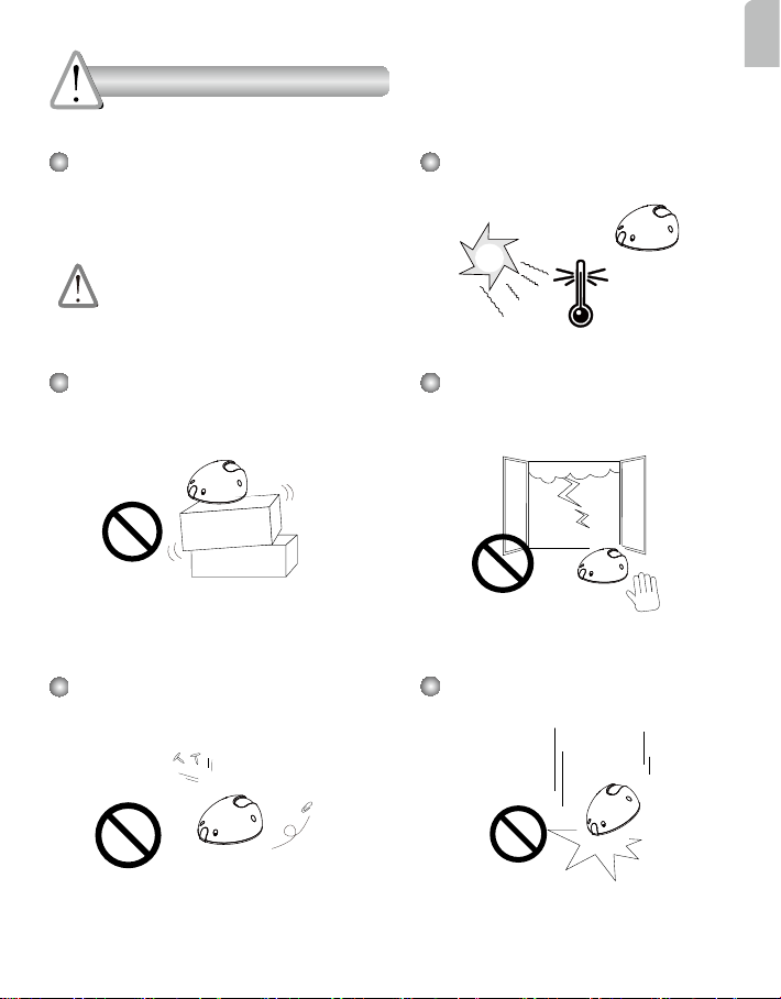
Warning Before Installation
English
Power off the Network Camera as
soon as smoke or unusual odors are
detected.
Contact your distributor in the event of
occurrence.
Do not place the Network Camera on
unsteady surfaces.
Do not insert sharp or tiny objects
into the Network Camera.
Refer to your user’s manual for
the operating temperature.
Do not touch the Network Camera
during a lightning storm.
Do not drop the Network Camera.
EN - 1
Page 3
1
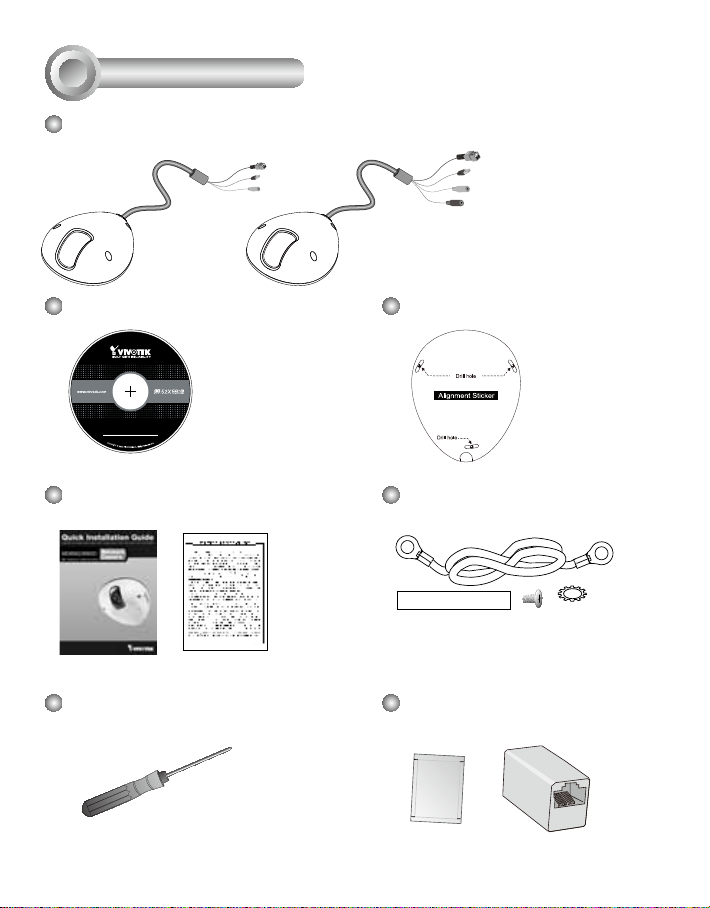
Package Contents
MD8562
(PoE)
(With power cord)
Software CD
5
1
0
G
0
0
1
0
2
0
Quick Installation Guide /
Warranty Card
Screwdriver
MD8562D
General I/O Terminal Block
Ethernet 10/100 RJ45 Plug
Microphone In (pink)
Power Cord Socket (black)
Alignment Sticker
Ground Wire / Screws
Moisture Absorber / RJ45 Female/
Female Coupler
EN - 2
Page 4
2
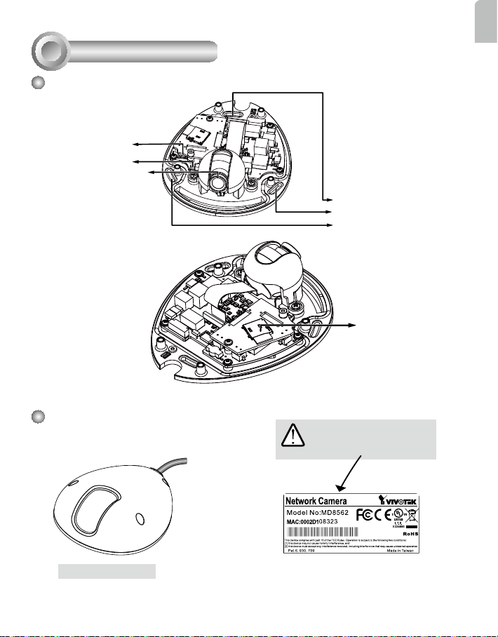
Physical Description
Inner View
Reset button
Status LED
Lens
English
Screw Holes
MicroSD/SDHC
Card Slot
Outer View
Waterproof Level: IP67
EN - 3
IMPORTANT!
Record the MAC address before
installing the camera.
Page 5
3
Hardware Installation
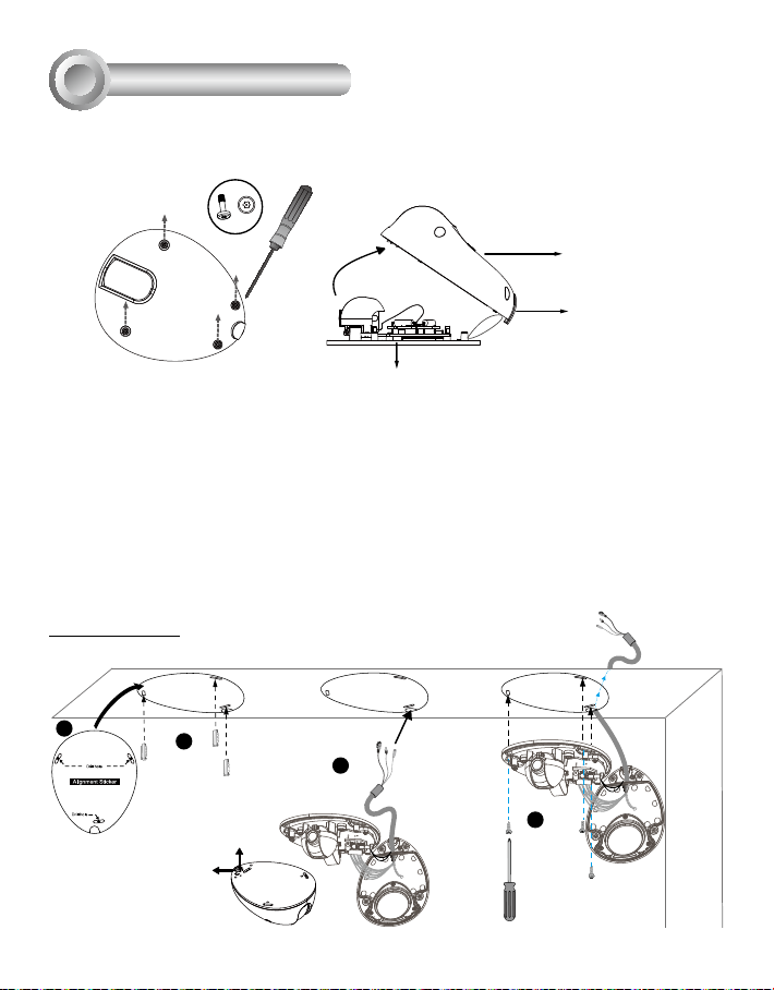
First, use the supplied screwdriver to detach the dome cover from the camera base. Insert your
MicroSD/SDHC Card if necessary.
Tamper-proof Screw
Dome Cover
Plastic Cover
Camera Base
Then, follow the steps below to install the camera to either a ceiling or wall:
1. Attach the supplied alignment sticker to the ceiling/wall.
2. Using the 3 screw circles on the sticker, drill 3 pilot holes into the ceiling/wall. Then hammer the
plastic anchors into the holes if necessary.
3. This Network Camera can be mounted with the cable routed through the ceiling/wall or from the
side. If you want to feed the cable through the ceiling/wall, drill a cable hole A as shown in the
picture. If the cable goes through the rear opening of the dome cover, please remove the plastic
cover (B).
4. Through the 3 holes on the camera base, insert the screws to corresponding holes and secure
the camera base with a screwdriver.
Ceiling Mount
1
2
A
B
A
3
4
EN - 4
Page 6
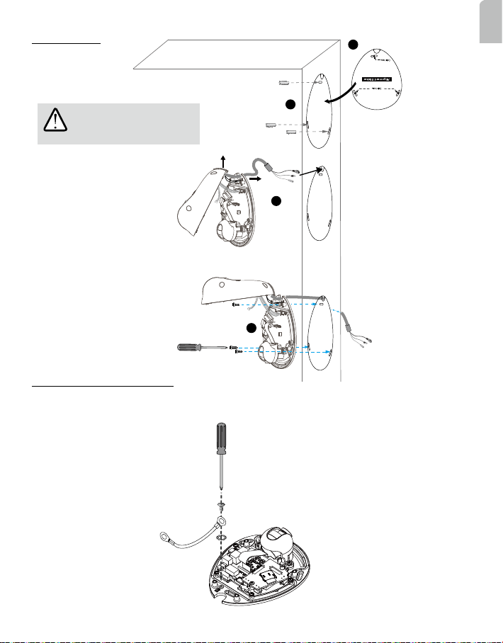
Wall Mount
1
English
IMPORTANT!
Please secure the screws tightly
to avoid moisture.
B
2
A
3
4
Installing the Ground Wire
As shown in the gure below, secure one side of the supplied ground wire to the screw hole, route
the wire, and attach the other end to a junction box or a grounded conduit.
EN - 5
Page 7

Network Deployment
4
General Connection (without PoE) (MD8562D)
1. If you have external DI devices, make the connection from general I/O terminal block.
2. Use the supplied RJ45 female/female coupler to connect the Network Camera to a switch.
Use a Category 5 Cross Cable when Network Camera is directly connected to PC.
3. Connect the power cable from the Network Camera to a power outlet.
+ : Digital input
- : Digital input
Ethernet Switch
1
EN - 6
2
L
I
N
K
POW
ER
C
O
LL
I
S
RE
ION
CEIVE
1
PARTITIO
2
3
N
4
5
3
Page 8

Power over Ethernet (PoE) (MD8562)
When using a PoE-enabled switch
This Network Camera is PoE-compliant, allowing transmission of power and data via a single
Ethernet cable. Follow the below illustration to connect the camera to a PoE-enabled switch via
Ethernet cable.
L
I
N
POW
ER
K
C
O
LL
I
S
RE
ION
CEIVE
1
PARTITIO
2
3
N
4
5
PoE Switch
NOTE:
1. This equipment is only to be connected to PoE networks
without routing to outside plants.
2. For PoE input connection, use only UL listed I.T.E. with
PoE output.
3. The DC power adaptor, if used, should comply with:
O/P: 12Vdc, 1.5A min., L.P.S. certied.
When using a non-PoE switch
Use a PoE power injector (optional) to connect between the Network Camera and a non-PoE
switch.
PoE Power Injector
(optional)
English
Non-PoE Switch
EN - 7
L
I
N
POW
ER
C
O
K
LL
I
RECEIVE
S
ION
1
PARTITIO
2
3
N
4
5
Page 9

Assigning an IP Address
5
1. Install “Installation Wizard 2” from the Software Utility directory on the software CD.
2. The program will conduct an analysis of your network environment. After your network is analyzed, please click on the “Next” button to continue the program.
Installation
Wizard 2
3. The program will search for VIVOTEK Video Receivers, Video Servers, and Network Cameras
on the same LAN.
4. After a brief search, the main installer window will pop up. Double-click on the MAC address
that matches the one printed on the camera label or the serial number on the package box
label to open a browser management session with the Network Camera.
00-02-D1-10-83-23 192.168.5.151 MD8562
0002D108323
EN - 8
Page 10

6
Ready to Use
1. A browser session with the Network Camera should prompt as shown below.
2. You should be able to see live video from your camera. You may also install the 32-channel
recording software from the software CD in a deployment consisting of multiple cameras.
For its installation details, please refer to its related documents.
For further setup, please refer to the user's manual on the software CD.
Adjusting the Lens
7
To adjust the viewing angle
Loosen the screws (not removing
them) on the sides of lens module.
Adjust the lens to a desired viewing
angle as shown on the right.
When done, fasten the screws so that
lens orientation can be xed
and withstand shock and
vibration.
1
2
English
EN - 9
90°
Page 11

Fine-tune the Camera Focus
The focus of this network camera is set from 1.0 meter to innity by factory default. If you want to
focus on objects closer than 1.0m or the lens has lost focus, please ne tune it in the following way.
1. Loosen the lens lock screw under the lens
module.
2. Manually rotate the lens to ne-tune the focus
until the live image is clear.
3. Tighten the lens lock screw.
Loosen the lens lock screw.
Completion
8
Tear down the aluminum foil vacuum bag and
take out the moisture absorber. Attach the
supplied moisture absorber to the inner side of
the dome cover. (Please replace the absorber
whenever you open the dome cover.)
Attach the dome cover to camera. Secure
the dome screws with the supplied
screwdriver. Finally, make sure all parts of
the camera are securely installed.
IMPORTANT!
Please secure the screws
tightly to avoid moisture.
EN - 10
Page 12

Copyright 2011 VIVOTEK INC. All rights reserved.
c
P/N:625015501G Ver1.1
 Loading...