

Vivotek IP9181-H User Manual

Box
IP9181-H
Network Camera
User’s Manual
5MP • WDR Pro • Remote Back Focus • SNV • 3DNR
Rev. 1.0

VIVOTEK
Table of Contents
Overview
Revision History ..................................................................................................................................................... 3
Read Before Use .................................................................................................................................................... 4
Package Contents .................................................................................................................................................. 4
Symbols and Statements in this Document ............................................................................................................ 4
Physical Description ............................................................................................................................................... 5
Hardware Installation .............................................................................................................................................. 6
Network Deployment ............................................................................................................................................ 13
Software Installation ............................................................................................................................................. 16
Ready to Use ........................................................................................................................................................ 17
Auto Focus ........................................................................................................................................................... 18
Accessing the Network Camera
Using Web Browsers ............................................................................................................................................ 19
Using RTSP Players ............................................................................................................................................. 22
Using 3GPP-compatible Mobile Devices .............................................................................................................. 23
Using VIVOTEK Recording Software ................................................................................................................... 24
Main Page
Client Settings
Conguration
System > General settings ................................................................................................................................... 36
System > Homepage layout ................................................................................................................................ 37
System > Logs ..................................................................................................................................................... 40
System > Parameters .......................................................................................................................................... 42
System > Maintenance ......................................................................................................................................... 43
Media > Image ................................................................................................................................................... 47
Media > Video ...................................................................................................................................................... 59
Media > Audio....................................................................................................................................................... 67
Network > General settings .................................................................................................................................. 68
Network > Streaming protocols .......................................................................................................................... 76
Network > SNMP (Simple Network Management Protocol) ................................................................................. 85
Security > User accounts ..................................................................................................................................... 86
Security > HTTPS (Hypertext Transfer Protocol over SSL) .......................................................................87
Security > Access List ........................................................................................................................................ 94
PTZ > PTZ settings .............................................................................................................................................. 99
PTZ ..................................................................................................................................................................... 102
Mechanical PTZ Operation ................................................................................................................................. 102
Event > Event settings........................................................................................................................................ 105
Applications > Motion detection.......................................................................................................................... 119
Applications > DI and DO ................................................................................................................................. 122
Applications > Tampering detection ................................................................................................................... 123
Applications > Audio detection ......................................................................................................................... 124
Applications > Package management - a.k.a., VADP (VIVOTEK Application Development Platform) ............. 126
Snapshot Focus ................................................................................................................................................. 129
Recording > Recording settings ........................................................................................................................ 131
....................................................................................................................................................................
...........................................................................................................................
................................................................................................................................................................
.........................................................................................................................................................
...........................................................................................................................................................
3
19
25
30
35
2 - User's Manual

VIVOTEK
Local storage > SD card management ..................................................................................................... 136
Local storage > Content management ..................................................................................................... 137
Appendix
URL Commands for the Network Camera ................................................................................................ 140
Technical Specications ...........................................................................................................................313
Technology License Notice .......................................................................................................................314
Electromagnetic Compatibility (EMC) .......................................................................................................315
....................................................................................................................................................
140
Overview
VIVOTEK’s IP9181-H is a brand-new professional H.265 box network camera offering up
to 30 fps @ 5-Megapixel and 60 fps @ 1080p with superb image quality at all resolutions
and frame rates. By utilizing VIVOTEK’s sophisticated Smart Stream II, the camera is able
to optimize resolution for a desired object or area and thus ensure maximum efciency of
bandwidth usage. Combining both H.265 and Smart Stream II, the IP9181-H can reduce
both bandwidth and storage consumption by up to 80%* while keeping the high standard of
image quality as a 5-Megapixel camera. This unique combination of high resolution and low
storage consumption make the IP9181-H suitable for a wide range of video surveillance
applications, including government and industrial buildings, retail environments, airports,
railway stations and schools.
Additionally, employing WDR Pro allows the camera to capture both the dark and bright
areas of an image, combining the differences to create a highly realistic representation
of the original scene. Further improving the IP9181-H’s range of operating conditions,
SNV technology makes high quality full-color surveillance video possible under low-light
conditions. Together, these features enable the camera to provide video quality strikingly
close to the capabilities of the human eye. Further enhancing the camera’s ability to adapt
to its environment, precise software controls maintain the iris opening of the IP9181-H’s
lens at an optimal level at all times, resulting in superior sharpness as well as depth of eld.
Finally, the IP9181-H is also endowed with VIVOTEK’s RBF (Remote Back Focus) system,
enabling the installer to adjust focus both more precisely and with greater exibility.
Revision History
■ Rev. 1.0: Initial release.
User's Manual - 3

VIVOTEK
i
Read Before Use
The use of surveillance devices may be prohibited by law in your country. The Network Camera
is not only a high-performance web-ready camera but can also be part of a exible surveillance
system. It is the user’s responsibility to ensure that the operation of such devices is legal before
installing this unit for its intended use.
It is important to first verify that all contents received are complete according to the Package
Contents listed below. Take note of the warnings in the Quick Installation Guide before the Network
Camera is installed; then carefully read and follow the instructions in the Installation chapter to
avoid damage due to faulty assembly and installation. This also ensures the product is used
properly as intended.
The Network Camera is a network device and its use should be straightforward for those who
have basic networking knowledge. It is designed for various applications including video sharing,
general security/surveillance, etc. The Configuration chapter suggests ways to best utilize the
Network Camera and ensure proper operations. For creative and professional developers, the URL
Commands of the Network Camera section serves as a helpful reference to customizing existing
homepages or integrating with the current web server.
Package Contents
■ IP9181-H.
■ Lens module
■ Software CD
■ Camera stand
■ Quick Installation Guide
Symbols and Statements in this Document
INFORMATION: provides important messages or advices that might help prevent
inconvenient or problem situations.
NOTE: Notices provide guidance or advices that are related to the functional integrity of
the machine.
Tips: Tips are useful information that helps enhance or facilitae an installation, function,
or process.
WARNING! or IMPORTANT!: These statements indicate situations that can be
dangerous or hazardous to the machine or you.
Electrical Hazard: This statement appears when high voltage electrical hazards might
occur to an operator.
4 - User's Manual

Physical Description
Front Panel
Lens
Rear Panel
VIVOTEK
Light Sensor
MicroSD Card Slot
Status LED
Audio In
Audio Out
Recessed Reset Button
General I/O Terminal Block
Ethernet 10/100 RJ45 Socket
User's Manual - 5

VIVOTEK
Hardware Installation
1. Jot down the camera's MAC address for later reference.
XXXXXX
0002D10766AD
2. Install the lens module to the camera.
3. Connect the iris control cable to the socket on camera.
1
6 - User's Manual

4. Remove the protection sheet from the light sensor.
VIVOTEK
Fasten the lens module to the camera, and notice that the lens module does not block
the the light sensor. You can still turn the camera when the lens module is secured to
the camera .
User's Manual - 7

VIVOTEK
5. Install the camera stand to camera.
6. Connect an Ethernet cable to the camera.
When choosing the lens for your camera, please notice the specications as below. The
screw mount (distance A-C) must be shorter than 5.2mm; in case that the bottom of screw
mount may hit the IR Cut Filter.
8 - User's Manual

VIVOTEK
7. Install a MicroSD card, and, if preferred, connect DI/DO wires to the terminal block The
AC/DC pins can accept either 12V or 24V power input with no polarity.
icro
M
SD
DO+ (+5V)
DODI1+
DI2+
DI3+
DI- (common GND)
RS485RS485+
AC/DC pw
AC/DC pw
12V or 24V, no
polarity
The DO pin can provide a 5V output, and the max. load is 50mA.
User's Manual - 9

VIVOTEK
DI/DO Diagram
DI-
VDC
DO+
BJT transistor
DI+
DO-
DO+
DI-
DI+
Switch
NO NC
Switch
Relay
VDC
External
power source
AC
Source
External
device
AC
BJT transistor
DO-
NO NC
Relay
Source
External
device
1. The DO+ pin provides 5V output voltage, and the max. load is 50mA.
2. The max. voltage for DO- pins is 80VDC (External power).
In order to control AC devices, the above diagram can be taken in consideration. The
diagram uses a relay to control the ON/OFF condition of the AC device.
3. An external relay can be triggered by using DO+ or by an external power source,
depending on the type of relay you use.
4. In case of using an individual relay (instead of using a relay module), for protection
against voltage or current spikes, a transient voltage suppression diode must be
connected in parallel with the inductive load.
10 - User's Manual
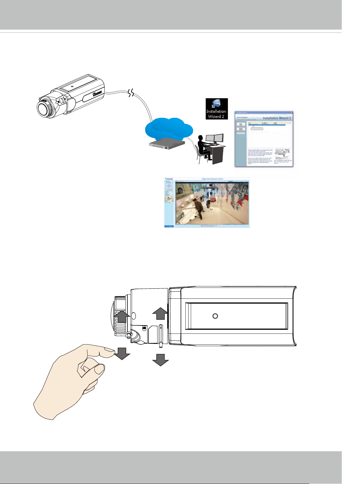
8. Install the IW2 utility. Use the IW2 utility to nd the camera on LAN. Open a web
∞
console to have a live view.
IW2
00-02-D1-73-02-02 192.168.5.151 FD8168
LAN
Browser
0002D1730202
VIVOTEK
9. With a live view on screen, adjust the image zoom and focus using the pullers on lens
module.
T
N
W
User's Manual - 11

VIVOTEK
You can purchase the AE-236/237/241/242 enclosure for outdoor installations.
LED Denitions
Item LED status Description
LED De`nitions
1 Steady Red Powered and system booting, or network
failed
Red LED off Power off
Green LED off Network is disconnected
2 Steady Red and Green LED blinks every 1
sec.
3 Green LED blinks every 1 sec. and RED
LED blinks consecutively every 0.15 sec.
4 Green and RED blink every 0.15 sec, Green
and RED light on, then blink again.
5 RED LED is on, Green LED blinks and RED
LED is constantly on.
Green and RED LEDs are constantly on. Status after a reset (network
Connected to network
Upgrading rmware
Restoring defaults
Status after a reset (network connected)
disconnected)
12 - User's Manual

VIVOTEK
Hardware Reset
Reset Button
The reset button is used to reset the system or restore the factory default settings.
Sometimes resetting the system can return the camera to normal operation. If the system
problems remain after reset, restore the factory settings and install again.
Reset: Press the recessed reset button. Wait for the Network Camera to reboot.
Restore: Press and hold the reset button until the status LED rapidly blinks. Note that all
settings will be restored to factory default. Upon successful restore, the status LED will
blink green and red during normal operation.
MicroSD/SDHC/SDXC Card Capacity
This network camera is compliant with SD/SDHC/SDXC 16GB / 8GB / 32GB / 64GB and
other preceding standard SD cards.
Network Deployment
General Connection (PoE)
When using a PoE-enabled switch
The Network Camera is PoE-compliant, allowing transmission of power and data via a single Ethernet cable. Follow the below illustration to connect the Network Camera to a PoEenabled switch via Ethernet cable.
802.3af
PoE Switch
User's Manual - 13

VIVOTEK
When using a non-PoE switch
Use a PoE power injector (optional) to connect between the Network Camera and a nonPoE switch.
PoE Power Injector
(optional)
Non-PoE Switch
NOTE:
1. The camera is only to be connected to PoE networks without routing to outside plants.
2. For PoE connection, use only UL listed I.T.E. with PoE output.
Internet connection via a router
Before setting up the Network Camera over the Internet, make sure you have a router and follow
the steps below.
1. Connect your Network Camera behind a router, the Internet environment is illustrated below.
Regarding how to obtain your IP address, please refer to Software Installation on page 16 for
details.
IP address : 192.168.0.3
Subnet mask : 255.255.255.0
Default router : 192.168.0.1
Internet
WAN (Wide Area Network )
Router IP address : from ISP
LINK
POWER
COLLISION
RECEIVE
1
2
PARTITION
3
4
5
14 - User's Manual
Cable or DSL Modem
LAN (Local Area Network)
Router IP address : 192.168.0.1
IP address : 192.168.0.2
Subnet mask : 255.255.255.0
Default router : 192.168.0.1

VIVOTEK
2. In this case, if the Local Area Network (LAN) IP address of your Network Camera is
192.168.0.3, please forward the following ports for the Network Camera on the router.
■ HTTP port: default is 80
■ RTSP port: default is 554
■ RTP port for video: default is 5556
■ RTCP port for video: default is 5557
If you have changed the port numbers on the Network page, please open the ports
accordingly on your router. For information on how to forward ports on the router, please
refer to your router’s user’s manual.
3. Find out the public IP address of your router provided by your ISP (Internet Service
Provider).
Use the public IP and the secondary HTTP port to access the Network Camera from the
Internet. Please refer to Network Type on page 69 for details.
Internet connection with static IP
Choose this connection type if you are required to use a static IP for the Network Camera.
Please refer to LAN setting on page 68 for details.
Internet connection via PPPoE (Point-to-Point over Ethernet)
Choose this connection type if you are connected to the Internet via a DSL Line. Please
refer to PPPoE on page 69 for details.
Congure the router, virtual server or rewall, so that the router can forward any data coming into a pre-congured port number to a network camera on the private network, and
allow data from the camera to be transmitted to the outside of the network over the same
path.
From Forward to
122.146.57.120:8000 192.168.2.10:80
122.146.57.120:8001 192.168.2.11:80
... ...
When properly congured, you can access a camera behind the router using the HTTP
request such as: http://122.146.57.120:8000
If you change the port numbers on the Network conguration page, please open the ports
accordingly on your router. For example, you can open a management session with your
router to congure access through the router to the camera within your local network.
Please consult your network administrator for router conguration if you have troubles with
the conguration.
User's Manual - 15

VIVOTEK
For more information with network conguration options (such as that of streaming ports),
please refer to Conguration > Network Settings. VIVOTEK also provides the automatic port
forwarding feature as an NAT traversal function with the precondition that your router must support the UPnP port forwarding feature.
Software Installation
Installation Wizard 2 (IW2), a software included in the product CD, helps you set up your
Network Camera on the LAN.
IW
1. Install IW2 under the Software Utility directory from the software CD.
Double-click the IW2 shortcut on your desktop to launch the program.
2. The program will conduct an analysis of your network environment.
After your network environment is analyzed, please click Next to continue the program.
2
Installation
Wizard 2
3. The program will search for all VIVOTEK network devices on the same LAN.
16 - User's Manual

VIVOTEK
4. After a brief search, the installer window will prompt. Click on the MAC and model name
that matches the one printed on the product label. You can then double-click on the address
to open a management session with the Network Camera.
Network Camera
Model No: IP9181-H
MAC:0002D1730202
R o H S
This device complies with part 15 of the FCC rules. Operation is subject to the following two conditions:
(1)This device may not cause harmful interference, and
(2) this device must accept any interference received, including interference that may cause undesired operation.
Pat. 6,930,709
Made in Taiwan
00-02-D1-73-02-02 192.168.5.151 IP9181-H
0002D1730202
Ready to Use
1. A browser session with the Network Camera should prompt as shown below.
2. You should be able to see live video from your camera. You may also install the 32-channel
recording software from the software CD in a deployment consisting of multiple cameras. For
its installation details, please refer to its related documents.
User's Manual - 17

VIVOTEK
Auto Focus
On the web session, visit the Conguration > Image > Focus window. Perform the Auto
Focus function for best image. However, if you have cascaded cameras, do this one
by one. Do not perform this function simultaneously on multiple cameras because the
motorized lens also consume considerable power, and may cause the last camera on the
line to hang.
Focus window
x
18 - User's Manual

VIVOTEK
Accessing the Network Camera
This chapter explains how to access the Network Camera through web browsers, RTSP players,
3GPP-compatible mobile devices, and VIVOTEK recording software.
Using Web Browsers
Use Installation Wizard 2 (IW2) to access the Network Cameras on LAN.
If your network environment is not a LAN, follow these steps to access the Netwotk Camera:
1. Launch your web browser (e.g., Microsoft
2. Enter the IP address of the Network Camera in the address eld. Press Enter.
3. Live video will be displayed in your web browser.
4. If it is the rst time installing the VIVOTEK network camera, an information bar will prompt as
shown below. Follow the instructions to install the required plug-in on your computer.
®
Internet Explorer or Mozilla Firefox).
NOTE:
NOTE
► For Mozilla Firefox or Chrome users, your browser will use QuickTime to stream the live
video. If you don’t have QuickTime on your computer, please download it rst, then launch
the web browser.
User's Manual - 19

VIVOTEK
► By default, the Network Camera is not password-protected. To prevent unauthorized access,
it is highly recommended to set a password for the Network Camera.
For more information about how to enable password protection, please refer to Security on
page 86.
®
► If you see a dialog box indicating that your security settings prohibit running ActiveX
®
Controls, please enable the ActiveX
Controls for your browser.
1. Choose Tools > Internet Options > Security > Custom Level.
2. Look for Download signed ActiveX
®
controls; select Enable or Prompt. Click OK.
3. Refresh your web browser, then install the ActiveX
complete installation.
®
control. Follow the instructions to
20 - User's Manual

IMPORTANT:
Currently the Network Camera utilizes 32-bit ActiveX plugin. You CAN NOT open a
•
management/view session with the camera using a 64-bit IE browser.
If you encounter this problem, try execute the Iexplore.exe program from C:\Windows\
•
SysWOW64. A 32-bit version of IE browser will be installed.
On Windows 7, the 32-bit explorer browser can be accessed from here:
•
C:\Program Files (x86)\Internet Explorer\iexplore.exe
If you open a web session from the IW2 utility, a 32-bit IE browser will be opened.
•
Tips:
VIVOTEK
1. The onscreen Java control can malfunction under the following situations: A PC connects to different cameras that are using the same IP address (or the same camera
running different rmware versions). Removing your browser cookies will solve this
problem.
2. If you encounter problems with displaying the conguration menus or UI items, try disable the Compatibility View on IE8 or IE9.
You may also press the F12 key to open the developer tools utility, and then change the
Browser Mode to the genuine IE8 or IE9 mode.
• In the event of plug-in compatibility issues, you may try to uninstall the plug-in that was
previously installed.
User's Manual - 21

VIVOTEK
Using RTSP Players
To view the streaming media using RTSP players, you can use one of the following players that
support RTSP streaming.
Quick Time Player
VLC media player
VLC media player
1. Launch the RTSP player.
mpegable Player
2. Choose File > Open URL. A URL dialog box will pop up.
3. The address format is rtsp://<ip address>:<rtsp port>/<RTSP streaming access name for
pvPlayer
stream1 or stream2>
As most ISPs and players only allow RTSP streaming through port number 554, please set the
RTSP port to 554. For more information, please refer to RTSP Streaming on page 77.
For example:
rtsp://192.168.5.151:554/live.sdp
4. The live video will be displayed in your player.
For more information on how to configure the RTSP access name, please refer to RTSP
Streaming on page 77 for details.
Video 16:38:01 2012/01/25
22 - User's Manual

VIVOTEK
Video quality (Constant bit rate) 40kbps
Using 3GPP-compatible Mobile Devices
To view the streaming media through 3GPP-compatible mobile devices, make sure the Network
Camera can be accessed over the Internet. For more information on how to set up the Network
Camera over the Internet, please refer to Setup the Network Camera over the Internet on page
13.
To utilize this feature, please check the following settings on your Network Camera:
1. Because most players on 3GPP mobile phones do not support RTSP authentication, make
sure the authentication mode of RTSP streaming is set to disable.
For more information, please refer to RTSP Streaming on page 77.
2. As the the bandwidth on 3G networks is limited, you will not be able to use a large video size.
Please set the video streaming parameters as listed below.
For more information, please refer to Stream settings on page 59.
Video Mode H.264
Frame size 176 x 144
Maximum frame rate 5 fps
Intra frame period 1S
3. As most ISPs and players only allow RTSP streaming through port number 554, please set
the RTSP port to 554. For more information, please refer to RTSP Streaming on page 77.
4. Launch the player on the 3GPP-compatible mobile devices (e.g., Quick Time).
5. Type the following URL commands into the player.
The address format is rtsp://<public ip address of your camera>:<rtsp port>/<RTSP streaming
access name for stream # with small frame size and frame rate>.
For example:
You can configure Stream #2 into the suggested stream settings as listed above for live
viewing on a mobile device.
User's Manual - 23

VIVOTEK
Using VIVOTEK Recording Software
The product software CD also contains a VAST recording software, allowing simultaneous
monitoring and video recording for multiple Network Cameras. Please install the recording
software; then launch the program to add the Network Camera to the Channel list. For detailed
information about how to use the recording software, please refer to the user’s manual of the
software or download it from http://www.vivotek.com.
24 - User's Manual

VIVOTEK
Main Page
This chapter explains the layout of the main page. It is composed of the following sections:
VIVOTEK INC. Logo, Host Name, Camera Control Area, Configuration Area, Menu, and Live
Video Window.
Resize Buttons
VIVOTEK INC.
Logo
Camera Control
Area
Hide Button
Host Name
Configuration
Area
Live View Window
VIVOTEK INC. Logo
Click this logo to visit the VIVOTEK website.
Host Name
The host name can be customized to t your needs. The name can be changed especially there are many
cameras in your surveillance deployment. For more information, please refer to System on page 36.
Camera Control Area
Video Stream: This Network Camera supports multiple streams (streams 1 and 2) simultaneously. You
can select any of them for live viewing. For more information about multiple streams, please refer to page
59 for detailed information.
Manual Trigger: Click to enable/disable an event trigger manually. Please congure an event setting on
the Application page before you enable this function. A total of 3 event conguration can be congured.
For more information about event setting, please refer to page 105. If you want to hide this item on
the homepage, please go to Configuration> System > Homepage Layout > General settings >
Customized button to deselect the “show manual trigger button” checkbox.
User's Manual - 25

VIVOTEK
H.264/265 Protocol and Media Options
Conguration Area
Client Settings: Click this button to access the client setting page. For more information, please refer to
Client Settings on page 30.
Conguration: Click this button to access the conguration page of the Network Camera. It is suggested
that a password be applied to the Network Camera so that only the administrator can configure the
Network Camera. For more information, please refer to Conguration on page 35.
Language: Click this button to choose a language for the user interface. Language options are available
in: English, Deutsch, Español, Français, Italiano,
日本語
, Português,
簡体中文
, and
繁體中文
. Please
note that you can also change a language on the Conguration page; please refer to page 35.
Hide Button
You can click the hide button to hide or display the control panel.
Resize Buttons
:
Click the Auto button, the video cell will resize automatically to t the monitor.
Click 100% is to display the original homepage size.
Click 50% is to resize the homepage to 50% of its original size.
Click 25% is to resize the homepage to 25% of its original size.
Live Video Window
■ The following window is displayed when the video mode is set to H.264 or H.265:
Video Title
Title and Time
Zoom Indicator
Video (TPC-AV)
Video 17:08:56 2015/03/25
x4.0
Video Title: The video title can be congured. For more information, please refer to Video Settings on
page 47.
H.264 or H.265 Protocol and Media Options: The transmission protocol and media options for H.264 or
H.265 video streaming. For further conguration, please refer to Client Settings on page 30.
2015/03/25 17:08:56
Time
Video Control Buttons
Time: Display the current time. For further conguration, please refer to Media > Image > Genral settings
on page 47.
Title and Time: The video title and time can be stamped on the streaming video. For further conguration,
please refer to Media > Image > General settings on page 50.
26 - User's Manual

VIVOTEK
PTZ Panel: This Network Camera supports “digital“ (e-PTZ) pan/tilt/zoom control, which allows roaming
a smaller view frame within a large view frame. Please refer to PTZ settiings on page 99 for detailed
information.
Global View: Click on this item to display the Global View window. The Global View window contains a
full view image (the largest frame size of the captured video) and a oating frame (the viewing region of
the current video stream). The oating frame allows users to control the e-PTZ function (Electronic Pan/
Tilt/Zoom). For more information about e-PTZ operation, please refer to E-PTZ Operation on page 99.
For more information about how to set up the viewing region of the current video stream, please refer to
page 99.
The viewing region of
the curruent video
stream
The largest frame size
Note that the PTZ buttons on the panel are not operational unless you are showing only a portion of the
full image. If the live view window is displaying the full view, the PTZ buttons are not functional.
User's Manual - 27

VIVOTEK
Video Control Buttons: Depending on the Network Camera model and Network Camera conguration,
some buttons may not be available.
Snapshot: Click this button to capture and save still images. The captured images will be displayed
in a pop-up window. Right-click the image and choose Save Picture As to save it in JPEG (*.jpg) or BMP
(*.bmp) format.
Digital Zoom: Click and uncheck “Disable digital zoom” to enable the zoom operation. The navigation
screen indicates the part of the image being magnied. To control the zoom level, drag the slider bar. To
move to a different area you want to magnify, drag the navigation screen.
Pause: Pause the transmission of the streaming media. The button becomes the Resume button
after clicking the Pause button.
Stop: Stop the transmission of the streaming media. Click the Resume button to continue
transmission.
Start MP4 Recording: Click this button to record video clips in MP4 file format to your computer.
Press the
recording stops accordingly. To specify the storage destination and le name, please refer to MP4 Saving
Options on page 31 for details.
Volume: When the Mute function is not activated, move the slider bar to adjust the volume on the
local computer.
Mute: Turn off the volume on the local computer. The button becomes the Audio On button after
clicking the Mute button.
Talk: Click this button to talk to people around the Network Camera. Audio will project from
the external speaker connected to the Network Camera. Click this button
transmission.
Mic Volume: When the Mute function is not activated, move the slider bar to adjust the
microphone volume on the local computer.
Stop MP4 Recording button to end recording. When you exit the web browser, video
again to end talking
NOTE:
1. For a megapixel camera, it is recommended to use monitors of the 24" size or larger, and
are capable of 1600x1200 or better resolutions.
2. Below are the defaults for Audio settings:
For cameras with built-in microphone: Not Muted.
For cameras without built-in microphone: Muted.
To receive audio input from an external microphone, you may need to enable the audio input
from Media > Audio. Refer to page 67 for more information.
28 - User's Manual

VIVOTEK
Mute: Turn off the Mic volume on the local computer. The button becomes the Mic On button
after clicking the Mute button.
Full Screen: Click this button to switch to full screen mode. Press the “Esc” key to switch back to normal
mode.
■ The following window is displayed when the video mode is set to MJPEG:
Video Title
Title and Time
Video (HTTP-V)
Video 17:08:56 2015/07/25
2015/07/25 17:08:56
Time
Video Control Buttons
Video Title: The video title can be congured. For more information, please refer to Media > Image on
page 50.
Time: Display the current time. For more information, please refer to Media > Image on page 50.
Title and Time: Video title and time can be stamped on the streaming video. For more information, please
refer to Media > Image on page 50
.
Video Control Buttons: Depending on the Network Camera model and Network Camera conguration,
some buttons may not be available.
Snapshot: Click this button to capture and save still images. The captured images will be displayed
in a pop-up window. Right-click the image and choose Save Picture As to save it in JPEG (*.jpg) or BMP
(*.bmp) format.
Digital Zoom: Click and uncheck “Disable digital zoom” to enable the zoom operation. The navigation
screen indicates the part of the image being magnied. To control the zoom level, drag the slider bar. To
move to a different area you want to magnify, drag the navigation screen.
Start MP4 Recording: Click this button to record video clips in MP4 file format to your computer.
Press the
Stop MP4 Recording button to end recording. When you exit the web browser, video
recording stops accordingly. To specify the storage destination and le name, please refer to MP4 Saving
Options on page 31 for details.
Full Screen: Click this button to switch to full screen mode. Press the “Esc” key to switch back to normal
mode.
User's Manual - 29

VIVOTEK
Client Settings
This chapter explains how to select the stream transmission mode and saving options on the
local computer. When completed with the settings on this page, click Save on the page bottom
to enable the settings.
H.265/H.264 Media Options
Select to stream video or audio data or both. This is enabled only when the video mode is set to H.264 or
H.265.
H.265/H.264 Protocol Options
Depending on your network environment, there are four transmission modes of H.264 or H.265
streaming:
UDP unicast: This protocol allows for more real-time audio and video streams. However, network
packets may be lost due to network burst trafc and images may be broken. Activate UDP connection
when occasions require time-sensitive responses and the video quality is less important. Note that each
unicast client connecting to the server takes up additional bandwidth and the Network Camera allows up
to ten simultaneous accesses.
UDP multicast: This protocol allows multicast-enabled routers to forward network packets to all clients
requesting streaming media. This helps to reduce the network transmission load of the Network Camera
while serving multiple clients at the same time. Note that to utilize this feature, the Network Camera must
be configured to enable multicast streaming at the same time. For more information, please refer to
RTSP Streaming on page 77.
TCP: This protocol guarantees the complete delivery of streaming data and thus provides better video
quality. The downside of this protocol is that its real-time effect is not as good as that of the UDP protocol.
HTTP: This protocol allows the same quality as TCP protocol without needing to open specic ports for
streaming under some network environments. Users inside a firewall can utilize this protocol to allow
streaming data through.
30 - User's Manual
 Loading...