

Page 1
Bullet
IP8372
Network Camera
User’s Manual
Outdoor • Day & Night • Weather-proof • IP67 •
Cable Management
Rev. 1.1
Rev. 1.1
Page 2

VIVOTEK
Table of Contents
Overview
Revision History ...................................................................................................................................... 4
Read Before Use ..................................................................................................................................... 5
Package Contents ................................................................................................................................... 5
Physical Description ................................................................................................................................ 6
Installation
Hardware Installation ............................................................................................................................... 9
Network Deployment ............................................................................................................................. 13
Software Installation .............................................................................................................................. 16
Ready to Use ......................................................................................................................................... 17
Accessing the Network Camera
Using Web Browsers ............................................................................................................................. 19
Using RTSP Players .............................................................................................................................. 21
Using 3GPP-compatible Mobile Devices ............................................................................................... 22
Using VIVOTEK Recording Software .................................................................................................... 23
Main Page
Client Settings
Conguration
System > General settings .................................................................................................................... 36
System > Homepage layout ................................................................................................................. 38
System > Logs ...................................................................................................................................... 41
System > Parameters ........................................................................................................................... 42
System > Maintenance .......................................................................................................................... 43
Media > Image .................................................................................................................................... 47
Media > Video ....................................................................................................................................... 55
Media > Audio........................................................................................................................................ 61
Network > General settings ................................................................................................................... 62
Network > Streaming protocols ........................................................................................................... 70
Network > SNMP
Security > User Account ........................................................................................................................ 80
Security > HTTPS
Security > Access List ......................................................................................................................... 88
PTZ > PTZ settings ............................................................................................................................... 93
Event > Event settings........................................................................................................................... 96
Applications > Motion detection........................................................................................................... 109
Applications > DI and DO .................................................................................................................... 112
Applications > Tampering detection .................................................................................................... 112
Recording > Recording settings ......................................................................................................... 11 3
Local storage > SD card management ................................................................................................ 118
Local storage > Content management ................................................................................................ 11 9
Appendix
URL Commands for the Network Camera ........................................................................................... 122
Technical Specications ......................................................................................................................198
Technology License Notice ..................................................................................................................199
.....................................................................................................................................................
...................................................................................................................................................
............................................................................................................
.................................................................................................................................................
..........................................................................................................................................
............................................................................................................................................
(Simple Network Management Protocol) ......................................................79
(Hypertext Transfer Protocol over SSL)
................................................................................................................................................
................................................. 81
4
9
19
24
29
35
122
2 - User's Manual
Page 3

VIVOTEK
Electromagnetic Compatibility (EMC) .......................................................................................................200
User's Manual - 3
Page 4

VIVOTEK
Overview
VIVOTEK IP8372 is a professional bullet camera offering 5-Megapixel or 1080p Full HD
resolution with superb image quality up to 30 fps. Featuring 5-Megapixel resolution and high-
performance H.264/MPEG-4/MJPEG compression technology, the IP8372 offers extra-smooth
video and wide coverage.
The IP8372 employs many advanced features to allow users to fully utilize the high denition
video. The ePTZ function enables users to zoom in and focus on a region of interest (ROI) in the
camera view with only a few clicks of a mouse.
For installers, properly adjusting the focus of a megapixel network camera can be difcult due to
the level of image detail. The Smart Focus System allows for easy installation and adjustment
by adopting a lens with a built-in stepper motor that can remotely control the focal length and
precisely adjust the camera focus, offering hassle-free installation and maintenance.
Aimed at outdoor surveillance, the IP8372 is furnished with an auto-iris lens, a removable IRcut lter, and 30-meter IR illuminators for superior image quality around the clock. Moreover, the
IP67-rated housing protects against rain and dust and ensures functional operation in all types
of weather conditions. For easy management and waterproong, the IP8372 is also equipped
with a mounting bracket that conceals all cables within.
With other advanced features such as tamper detection, 802.3af compliant PoE, SD/SDHC/
SDXC card on-board storage, and two-way audio, the IP8372 is an all-in-one network camera
for detailed surveillance in outdoor environments.
Revision History
■ Rev. 1.0: Initial release
■ Rev. 1.1: Updated URL commands in the Appendix
4 - User's Manual
Page 5

VIVOTEK
i
Read Before Use
The use of surveillance devices may be prohibited by law in your country. The Network Camera
is not only a high-performance web-ready camera but can also be part of a exible surveillance
system. It is the user’s responsibility to ensure that the operation of such devices is legal before
installing this unit for its intended use.
It is important to first verify that all contents received are complete according to the Package
Contents listed below. Take note of the warnings in the Quick Installation Guide before the Network
Camera is installed; then carefully read and follow the instructions in the Installation chapter to
avoid damage due to faulty assembly and installation. This also ensures the product is used
properly as intended.
The Network Camera is a network device and its use should be straightforward for those who
have basic networking knowledge. It is designed for various applications including video sharing,
general security/surveillance, etc. The Configuration chapter suggests ways to best utilize the
Network Camera and ensure proper operations. For creative and professional developers, the URL
Commands of the Network Camera section serves as a helpful reference to customizing existing
homepages or integrating with the current web server.
Package Contents
■ IP8372 with an RJ45 Cable
■
Sun Shield / Wrench / RJ45 Female-Female Coupler / Double-sided Tape / Screws
■ Wall Mount Bracket
■ CS-mount Lens
■
Waterproof Connector for RJ45 Ethernet Enclosure
■ Waterproof Connector (for backup use)
■ Alignment Sticker / Desiccant Bag
■ Warranty Card
■ Quick Installation Guide
■ Software CD
Symbols and Statements in this Document
INFORMATION: provides important messages or advices that might help prevent
inconvenient or problem situations.
NOTE: Notices provide guidance or advices that are related to the functional integrity of
the machine.
Tips: Tips are useful information that helps enhance or facilitae an installation, function,
or process.
WARNING! or IMPORTANT!: These statements indicate situations that can be
dangerous or hazardous to the machine or you.
Electrical Hazard: This statement appears when high voltage electrical hazards might
occur to an operator.
User's Manual - 5
Page 6

VIVOTEK
Physical Description
IR LED
Lens
Light Sensor
SD/SDHC/SDXC Card
Slot
NTSC-PAL switch
NTSC
PAL
Status LED
The LED indicates the status of the Network Camera.
Status LED
Auto Focus Button
Reset Button
General I/O Terminal
Block
Item LED status Description
Steady Red Power on and system booting
1
Red LED off Power off
2 Blink Red every 0.15 sec. Upgrading Firmware
3 Blink Red every 0.15 sec. Restoring default
6 - User's Manual
Page 7

DI/DO Diagram
Please refer to the following illustration for the connection method.
12V
+12V
PIN 1
Power+12V
PIN 2
Digital output
VIVOTEK
PIN 3 or 5
Digital input
PIN 4 or 6
Ground
Camera Power
BJT transistor
Gnd
Input
Output
4
1
5 or 6
2
VDC
Switch
Relay
+30
VDC
Max.
Camera Power
BJT transistor
Gnd
Input
Output
4
1
5 or 6
2
VDC
Switch
+12
VDC
Relay
User's Manual - 7
Page 8

VIVOTEK
Hardware Reset
Reset Button
The reset button is used to reset the system or restore the factory default settings. Sometimes
resetting the system can return the camera to normal operation. If the system problems remain
after reset, restore the factory settings and install again.
Reset: Press and release the recessed reset button. Wait for the Network Camera to reboot.
Restore: Press and hold the recessed reset button until the status LED rapidly blinks. Note that
all settings will be restored to factory default. Upon successful restore, the status LED will blink
green and red during normal operation.
SD/SDHC/SDXC Card Capacity
This network camera is compliant with SD/SDHC/SDXC 16GB / 8GB / 32GB and other
preceding standard SD cards.
8 - User's Manual
Page 9

VIVOTEK
Installation
Hardware Installation
1. Attach the alignment sticker to the wall. Drill four holes into the wall. Then hammer the
supplied plastic anchors into the holes and secure the plate with supplied screws.
2. Fix the intersection bracket to the side of the Network Camera with two screws.
3. Feed the RJ45 cable through the front opening of the wall mount bracket. (If you want to
use external devices such as sensors and alarms, please refer to the assembling steps
on the next page.)
4. Push the spring mortise and hook the bracket onto the groove of the wall mount bracket.
5. Secure the two screws on the other side of the wall mount bracket.
6. Hang the wall mount bracket to the mounting plate.
7. Fix the wall mount bracket with the supplied screw.
8. Adjust the angle of the wall mount bracket to aim at the shooting area.
1
2
3
5
4
6
8
7
User's Manual - 9
Page 10

VIVOTEK
Waterproof Connector
Components of the Waterproof Connector
Screw Nut (A)
Seal (B)
Seals (C)
Housing (D)
Sealing Nut (E)
Pin Denitions
Fix
Align
Open the rear cover by rotating to the
alignment mark, and pull the cover off the
canister.
J3
1 DO+ (12V)
2 Digital Output
3 Digital Input 1
4 Ground
5 Digital Input 2
6 Ground
7 TV Out +
J6
1
8
1
J3
1
8 TV Out -
8
J6
1 Ext. MIC
2 Audio Ground
3 Audio Line out
4 Audio Ground
5 Ground
6 DC 12V+
7 AC24V8 AC24V+
NOTE:
In addition to PoE (Power over Ethernet), you can also supply power to the camera using
pins #5~#8 from the terminal block J6, either using DC 12V or AC24V.
10 - User's Manual
Page 11

VIVOTEK
9-2
Assembling Steps
1. Disassemble the components of the waterproof connector into part (A) ~ (E) as shown
above.
2. Open the rear cover of the Network Camera.
3. Remove the rubber stopper from the bottom of the Network Camera and secure the
screw nut (A) tightly.
4. If you need extra power for external devices, please feed the power cable through the
wall mount bracket and the waterproof connector (E --> D --> B --> A) as the illustration
shown below. Then connect the power cord to the socket. Note: There are 7 holes on
the seal (B), and the widest hole with a crack on the side is specic for power cord.
5. If you have external devices such as sensors and alarms, feed the cables through the
wall mount bracket and the waterproof connector (E --> D --> B --> A) as the illustration
shown below. Then refer to the pin denition to connect them to the general I/O terminal
block. Note: The recommended cable gauge is 2.0 ~ 2.8 mm.
6. Push the seal (B) into the housing (D).
7. Insert the seals (C) into the empty holes on the seal (B) to avoid moisture.
8. Secure the sealing nut (E) tightly.
5
(A)
3
(B)
(D)
4
(E)
4
9. Open the aluminum foil vacuum bag
and take out the desiccant bag. Attach
the desiccant bag to the inner side of the
rear cover, to under the insulation pad,
and then tighten the rear cover. (Please
replace the desiccant bag with a new one
whenever you open the rear cover.)
(E)
7
6
(B)
(D)
8
9-2
(C)
9-1
User's Manual - 11
Page 12

VIVOTEK
Cabling Assembly: RJ45 Cable Connector
RJ45 Cable Dimension (unit: mm)
Assembling Steps
Prepare an Ethernet
1
cable and strip part of the
sheath.
Recommended cable gauge: 24AWG (0.51 mm)
2
Components of the Waterproof
Connector
Insert the housing into
the screw nut.
(C)
(D)
Sealing Nut (A)
Seal (B)
Screw Nut (C)
Housing (D)
Gasket (E)
Insert the seal into the
3
housing.
(B)
Insert the stripped Ether-
4
net cable through the sealing nut and the housing.
(A)
7
Attach the gasket to the
front of the housing.
(E)
Clamp the cable
5
with an RJ45 plug.
Push the RJ45 plug into
6
the housing, then secure
the sealing nut tightly.
Connect the Ethernet cable to the RJ45 cable and
8
secure the connectors tightly.
12 - User's Manual
Page 13

VIVOTEK
Network Deployment
Setting up the Network Camera over the Internet
This section explains how to congure the Network Camera to an Internet connection.
1. If you have external devices such as sensors and alarms, connect them to the general I/O
terminal block.
2. Connect the camera to a switch via Ethernet cable.
3. Connect either the DC 12V or AC 24V power wires from the Network Camera to a power
outlet.
3
2
POWER
COLLISION
1
2
3
Ethernet Switch
LINK
RECEIVE
PARTITION
4
5
There are several ways to set up the Network Camera over the Internet. The rst way is to set
up the Network Camera behind a router. The second way is to utilize a static IP. The third way is
using PPPoE.
User's Manual - 13
Page 14

VIVOTEK
Internet connection via a router
Before setting up the Network Camera over the Internet, make sure you have a router and follow
the steps below.
1. Connect your Network Camera behind a router, the Internet environment is illustrated below.
Regarding how to obtain your IP address, please refer to Software Installation on page 16 for
details.
IP address : 192.168.0.3
Subnet mask : 255.255.255.0
Default router : 192.168.0.1
IP address : 192.168.0.2
Subnet mask : 255.255.255.0
Default router : 192.168.0.1
Internet
Cable or DSL Modem
WAN (Wide Area Network )
Router IP address : from ISP
LINK
POWER
COLLISION
RECEIVE
1
2
PARTITION
3
4
5
LAN (Local Area Network)
Router IP address : 192.168.0.1
2. In this case, if the Local Area Network (LAN) IP address of your Network Camera is
192.168.0.3, please forward the following ports for the Network Camera on the router.
■ HTTP port: default is 80
■ RTSP port: default is 554
■ RTP port for audio: default is 5558
■ RTCP port for audio: default is 5559
■ RTP port for video: default is 5556
■ RTCP port for video: default is 5557
If you have changed the port numbers on the Network page, please open the ports accordingly
on your router. For information on how to forward ports on the router, please refer to your
router’s documentation.
3. Find out the public IP address of your router provided by your ISP (Internet Service Provider).
Use the public IP and the secondary HTTP port to access the Network Camera from the
Internet. Please refer to Network Type on page 61 for details.
Internet connection with static IP
Choose this connection type if you are required to use a static IP for the Network Camera.
Please refer to LAN settings on page 61 for details.
Internet connection via PPPoE (Point-to-Point over Ethernet)
Choose this connection type if you are connected to the Internet via a DSL Line. Please refer to
PPPoE on page 62 for details.
14 - User's Manual
Page 15

VIVOTEK
Set up the Network Camera through Power over Ethernet (PoE)
When using a PoE-enabled switch
The Network Camera is PoE-compliant, allowing transmission of power and data via a single
Ethernet cable. Follow the below illustration to connect the Network Camera to a PoE-enabled
switch via Ethernet cable.
power + data transmission
POWER
COLLISION
LINK
RECEIVE
1
2
PARTITION
3
4
5
PoE Switch
When using a non-PoE switch
If your switch/router does not support PoE, use a PoE power injector (optional) to connect
between the Network Camera and a non-PoE switch.
PoE Power Injector
(optional)
Non-PoE Switch
POWER
COLLISION
LINK
RECEIVE
1
2
PARTITION
3
4
5
User's Manual - 15
Page 16

VIVOTEK
Software Installation
Installation Wizard 2 (IW2), free-bundled software included on the product CD, helps you set up
your Network Camera on the LAN.
IW
1. Install IW2 under the Software Utility directory from the software CD.
Double click the IW2 shortcut on your desktop to launch the program.
2. The program will conduct an analysis of your network environment.
After your network environment is analyzed, please click Next to continue the program.
2
Installation
Wizard 2
3. The program will search for all VIVOTEK network devices on the same LAN.
4. After a brief search, the installer window will prompt. Click on the MAC and model name
that matches the one printed on the product label. You can then double-click on the address to
open a management session with the Network Camera.
Network Camera
Model No: IP8372
MAC:0002D1730202
This device complies with part 15 of the FCC rules. Operation is subject to the following two conditions:
(1)This device may not cause harmful interference, and
(2) this device must accept any interference received, including interference that may cause undesired operation.
Pat. 6,930,709
R o HS
Made in Taiwan
00-02-D1-73-02-02 192.168.5.151 IP8372
0002D1730202
16 - User's Manual
Page 17

Ready to Use
1. Access the Network Camera on the LAN.
2. Retrieve live video through a web browser or the included ST-7501 recording software.
2012/08/11 10:19:19
VIVOTEK
User's Manual - 17
Page 18

VIVOTEK
NOTE:
If you want to use the supplied sun shield for outdoor environments, please follow the
steps below to install:
1. Tighten the supplied two hex couplers.
2. Attach the supplied sun shield to the Network Camera and slide it to the desired position.
3. Fix the sun shield with the supplied two screws.
1
3
2
Accessories
VIVOTEK also provides other accessories for versatile applications as the following
illustrations. Please visit VIVOTEK's ofcial website for more purchase information.
Corner Mount Bracket
18 - User's Manual
Pole Mount Bracket
Page 19

VIVOTEK
Accessing the Network Camera
This chapter explains how to access the Network Camera through web browsers, RTSP players,
3GPP-compatible mobile devices, and VIVOTEK recording software.
Using Web Browsers
Use Installation Wizard 2 (IW2) to access to the Network Cameras on the LAN.
If your network environment is not a LAN, follow these steps to access the Netwotk Camera:
1. Launch your web browser (e.g., Microsoft
2. Enter the IP address of the Network Camera in the address eld. Press Enter.
3. The live video will be displayed in your web browser.
4. If it is the rst time installing the VIVOTEK network camera, an information bar will pop up as
shown below. Follow the instructions to install the required plug-in on your computer.
®
Internet Explorer or Mozilla Firefox).
NOTE:
NOTE
► For Mozilla Firefox users, your browser will use Quick Time to stream the live video. If you do
not have Quick Time on your computer, please download it rst, then launch the web browser.
► By default, the Network Camera is not password-protected. To prevent unauthorized access,
User's Manual - 19
Page 20

VIVOTEK
it is highly recommended to set a password for the Network Camera.
For more information about how to enable password protection, please refer to Security on
page 79.
► If you see a dialog box indicating that your security settings prohibit running ActiveX
®
Controls, please enable the ActiveX
Controls for your browser.
1. Choose Tools > Internet Options > Security > Custom Level.
®
2. Look for Download signed ActiveX
®
controls; select Enable or Prompt. Click OK.
3. Refresh your web browser, then install the ActiveX
complete installation.
®
control. Follow the instructions to
20 - User's Manual
Page 21

VIVOTEK
Using RTSP Players
To view the MPEG-4 streaming media using RTSP players, you can use one of the following
players that support RTSP streaming.
Quick Time Player
VLC media player
VLC media player
1. Launch the RTSP player.
mpegable Player
2. Choose File > Open URL. A URL dialog box will pop up.
3. The address format is rtsp://<ip address>:<rtsp port>/<RTSP streaming access name for
pvPlayer
stream1 or stream2>
As most ISPs and players only allow RTSP streaming through port number 554, please set the
RTSP port to 554. For more information, please refer to RTSP Streaming on page 70.
For example:
rtsp://192.168.5.151:554/live.sdp
4. The live video will be displayed in your player.
For more information on how to configure the RTSP access name, please refer to RTSP
Streaming on page 70 for details.
Video 16:38:01 2011/06/25
User's Manual - 21
Page 22

VIVOTEK
Using 3GPP-compatible Mobile Devices
To view the streaming media through 3GPP-compatible mobile devices, make sure the Network
Camera can be accessed over the Internet. For more information on how to set up the Network
Camera over the Internet, please refer to Setup the Network Camera over the Internet on page
13.
To utilize this feature, please check the following settings on your Network Camera:
1. Because most players on 3GPP mobile phones do not support RTSP authentication, make
sure the authentication mode of RTSP streaming is set to disable.
For more information, please refer to RTSP Streaming on page 70.
2. As the the bandwidth on 3G networks is limited, you will not be able to use a large video size.
Please set the video and audio streaming parameters as listed below.
For more information, please refer to Stream settings on page 88.
Video Mode MPEG-4
Frame size 176 x 144
Maximum frame rate 5 fps
Intra frame period 1S
Video quality (Constant bit rate) 40kbps
Audio type (GSM-AMR) 12.2kbps
3. As most ISPs and players only allow RTSP streaming through port number 554, please set
the RTSP port to 554. For more information, please refer to RTSP Streaming on page 70.
4. Launch the player on the 3GPP-compatible mobile devices (ex. Real Player).
5. Type the following URL commands into the player.
The address format is rtsp://<public ip address of your camera>:<rtsp port>/<RTSP streaming
access name for stream 3>.
For example:
rtsp://192.168.5.151:554/live.sdp
22 - User's Manual
Page 23

VIVOTEK
Using VIVOTEK Recording Software
The product software CD also contains recording software, allowing simultaneous monitoring
and video recording for multiple Network Cameras. Please install the recording software; then
launch the program to add the Network Camera to the Channel list. For detailed information
about how to use the recording software, please refer to the user’s manual of the software or
download it from http://www.vivotek.com.
User's Manual - 23
Page 24

VIVOTEK
VIVOTEK INC.
Logo
Camera Control
Area
Configuration
Area
Host Name
Resize Buttons
Hide Button
Live View Window
Main Page
This chapter explains the layout of the main page. It is composed of the following sections:
VIVOTEK INC. Logo, Host Name, Camera Control Area, Configuration Area, Menu, and Live
Video Window.
VIVOTEK INC. Logo
Click this logo to visit the VIVOTEK website.
Host Name
The host name can be customized to t your needs. For more information, please refer to System on page 35.
Camera Control Area
Video Stream: This Network Camera supports multiple streams (streams 1 ~ 3) simultaneously. You can
select either one for live viewing. For more information about multiple streams, please refer to page 88
for detailed information.
Manual Trigger: Click to enable/disable an event trigger manually. Please configure an event setting
on Application page before enable this function. A total of 3 event settings can be congured. For more
information about event setting, please refer to page 95. If you want to hide this item on the homepage,
please go to the System > Homepage Layout > General settings > Customized button to deselect
“show manual trigger button”.
Digital Output: Click to turn the digital output device on or off.
24 - User's Manual
Page 25

VIVOTEK
Auto Focus
There are two options for you to ne-tune the camera focus.
Auto Focus Button
Press the button, and the camera rmware will automatically perform an auto-sensing process on its
vari-focal lens to look for the best focus. The process takes about a minute to complete. This function
applies when you see the image is out of focus when the surrounding lighting condition is changed
drastically for some reasons. You can press the button for longer than 1 second to perform a full-range
scan. Forcing a re-focusing may improve the image quality.
PTZ Panel: This Network Camera supports “digital PTZ“ (e-PTZ). Please refer to PTZ settiings on page
92 for detailed information.
Global View: Click on this item to display the Global View window. The Global View window contains a
full view image (the largest frame size of the captured video) and a oating frame (the viewing region of
the current video stream). The oating frame allows users to control the e-PTZ function (Electronic Pan/
Tilt/Zoom). For more information about e-PTZ operation, please refer to E-PTZ Operation on page 92.
For more information about how to set up the viewing region of the current video stream, please refer to
page 88.
The viewing region of
the current video
stream
The largest frame size
NOTE:
1. For a megapixel camera, it is recommended to use monitors of the 24" size or larger,
and are capable of 1600x1200 or better resolutions.
2. Below are the defaults for Audio settings:
For cameras with built-in microphone: Not Muted.
For cameras without built-in microphone: Muted.
To receive audio into from external microphone, you may need to enable the audio input
from Media > Audio. Refer to page 60 for more information.
User's Manual - 25
Page 26

VIVOTEK
Conguration Area
Client Settings: Click this button to access the client setting page. For more information, please refer to
Client Settings on page 29.
Conguration: Click this button to access the conguration page of the Network Camera. It is suggested
that a password be applied to the Network Camera so that only the administrator can configure the
Network Camera. For more information, please refer to Conguration on page 34.
Language: Click this button to choose a language for the user interface. Language options are available
in: English, Deutsch, Español, Français, Italiano,
日本語
, Português,
簡体中文
, and
繁體中文
. Please
note that you can also change a language on the Conguration page; please refer to page 34.
Hide Button
You can click the hide button to hide the control panel or display the control panel.
Resize Buttons
:
Click the Auto button, the video cell will resize automatically to t the monitor.
Click 100% is to display the original homepage size.
Click 50% is to resize the homepage to 50% of its original size.
Click 25% is to resize the homepage to 25% of its original size.
Live Video Window
■ The following window is displayed when the video mode is set to H.264 / MPEG-4:
H.264 / MPEG-4 Protocol and Media Options
Video Title
Title and Time
Zoom Indicator
Video (TPC-AV)
Video 17:08:56 2011/06/25
x4.0
2012/08/25 17:08:56
Time
Video and Audio Control Buttons
Video Title: The video title can be congured. For more information, please refer to Video Settings on
page 88.
H.264 / MPEG-4 Protocol and Media Options: The transmission protocol and media options for H.264 /
MPEG-4 video streaming. For further conguration, please refer to Client Settings on page 29.
Time: Display the current time. For further conguration, please refer to Media > Image > Genral settings
on page 79.
Title and Time: The video title and time can be stamped on the streaming video. For further conguration,
please refer to Media > Image > General settings on page 79.
26 - User's Manual
Page 27

VIVOTEK
Video and Audio Control Buttons: Depending on the Network Camera model and Network Camera
conguration, some buttons may not be available.
Snapshot: Click this button to capture and save still images. The captured images will be displayed
in a pop-up window. Right-click the image and choose Save Picture As to save it in JPEG (*.jpg) or BMP
(*.bmp) format.
Digital Zoom: Click and uncheck “Disable digital zoom” to enable the zoom operation. The navigation
screen indicates the part of the image being magnied. To control the zoom level, drag the slider bar. To
move to a different area you want to magnify, drag the navigation screen.
Pause: Pause the transmission of the streaming media. The button becomes the Resume button
after clicking the Pause button.
Stop: Stop the transmission of the streaming media. Click the Resume button to continue
transmission.
Start MP4 Recording: Click this button to record video clips in MP4 file format to your computer.
Press the
Stop MP4 Recording button to end recording. When you exit the web browser, video
recording stops accordingly. To specify the storage destination and le name, please refer to MP4 Saving
Options on page 30 for details.
Volume: When the Mute function is not activated, move the slider bar to adjust the volume on the
local computer.
Mute: Turn off the volume on the local computer. The button becomes the Audio On button after
clicking the Mute button.
Talk: Click this button to talk to people around the Network Camera. Audio will project from
the external speaker connected to the Network Camera. Click this button
again to end talking
transmission.
Mic Volume: When the Mute function is not activated, move the slider bar to adjust the
microphone volume on the local computer.
Mute: Turn off the Mic volume on the local computer. The button becomes the Mic On button
after clicking the Mute button.
Full Screen: Click this button to switch to full screen mode. Press the “Esc” key to switch back to normal
mode.
User's Manual - 27
Page 28

VIVOTEK
■ The following window is displayed when the video mode is set to MJPEG:
Video Title
Title and Time
Video (HTTP-V)
Video 17:08:56 2011/06/25
2011/02/25 17:08:56
Time
Video Control Buttons
Video Title: The video title can be congured. For more information, please refer to Media > Image on
page 79.
Time: Display the current time. For more information, please refer to Media > Image on page 79.
Title and Time: Video title and time can be stamped on the streaming video. For more information, please
refer to Media > Image on page 79
.
Video and Audio Control Buttons: Depending on the Network Camera model and Network Camera
conguration, some buttons may not be available.
Snapshot: Click this button to capture and save still images. The captured images will be displayed
in a pop-up window. Right-click the image and choose Save Picture As to save it in JPEG (*.jpg) or BMP
(*.bmp) format.
Digital Zoom: Click and uncheck “Disable digital zoom” to enable the zoom operation. The navigation
screen indicates the part of the image being magnied. To control the zoom level, drag the slider bar. To
move to a different area you want to magnify, drag the navigation screen.
Start MP4 Recording: Click this button to record video clips in MP4 file format to your computer.
Press the
Stop MP4 Recording button to end recording. When you exit the web browser, video
recording stops accordingly. To specify the storage destination and le name, please refer to MP4 Saving
Options on page 30 for details.
Full Screen: Click this button to switch to full screen mode. Press the “Esc” key to switch back to normal
mode.
28 - User's Manual
Page 29

VIVOTEK
Client Settings
This chapter explains how to select the stream transmission mode and saving options on the
local computer. When completed with the settings on this page, click Save on the page bottom
to enable the settings.
H.264 / MPEG-4 Media Options
H.264/MPEG-4 Media Options
Select to stream video or audio data or both. This is enabled only when the video mode is set to H.264 or
MPEG-4.
H.264 / MPEG-4 Protocol Options
H.264/MPEG-4 Protocol Options
Depending on your network environment, there are four transmission modes of H.264 or MPEG-4
streaming:
UDP unicast: This protocol allows for more real-time audio and video streams. However, network
packets may be lost due to network burst trafc and images may be broken. Activate UDP connection
when occasions require time-sensitive responses and the video quality is less important. Note that each
unicast client connecting to the server takes up additional bandwidth and the Network Camera allows up
to ten simultaneous accesses.
UDP multicast: This protocol allows multicast-enabled routers to forward network packets to all clients
requesting streaming media. This helps to reduce the network transmission load of the Network Camera
while serving multiple clients at the same time. Note that to utilize this feature, the Network Camera must
be configured to enable multicast streaming at the same time. For more information, please refer to
RTSP Streaming on page 70.
TCP: This protocol guarantees the complete delivery of streaming data and thus provides better video
quality. The downside of this protocol is that its real-time effect is not as good as that of the UDP protocol.
HTTP: This protocol allows the same quality as TCP protocol without needing to open specic ports for
streaming under some network environments. Users inside a firewall can utilize this protocol to allow
streaming data through.
User's Manual - 29
Page 30

VIVOTEK
MP4 Saving Options
Users can record live video as they are watching it by clicking Start MP4 Recording on the main
page. Here, you can specify the storage destination and le name.
Folder: Specify a storage destination for the recorded video les.
File name prex: Enter the text that will be appended to the front of the video le name.
Add date and time sufx to the le name: Select this option to append the date and time to the end of the
le name.
CLIP_20110628-180853
File name prefix
Date and time suffix
The format is: YYYYMMDD_HHMMSS
Local Streaming Buffer Time
Due to the unsteady bandwidth ow, the live streaming may lag and not be very smoothly. If you enable
this option, the live streaming will be stored on the camera’s buffer area for a few seconds before playing
on the live viewing window. This will help you see the streaming more smoothly. If you enter 3000
Millisecond, the streaming will delay 3 seconds.
30 - User's Manual
Page 31
VIVOTEK
Joystick Settings
Enable Joystick
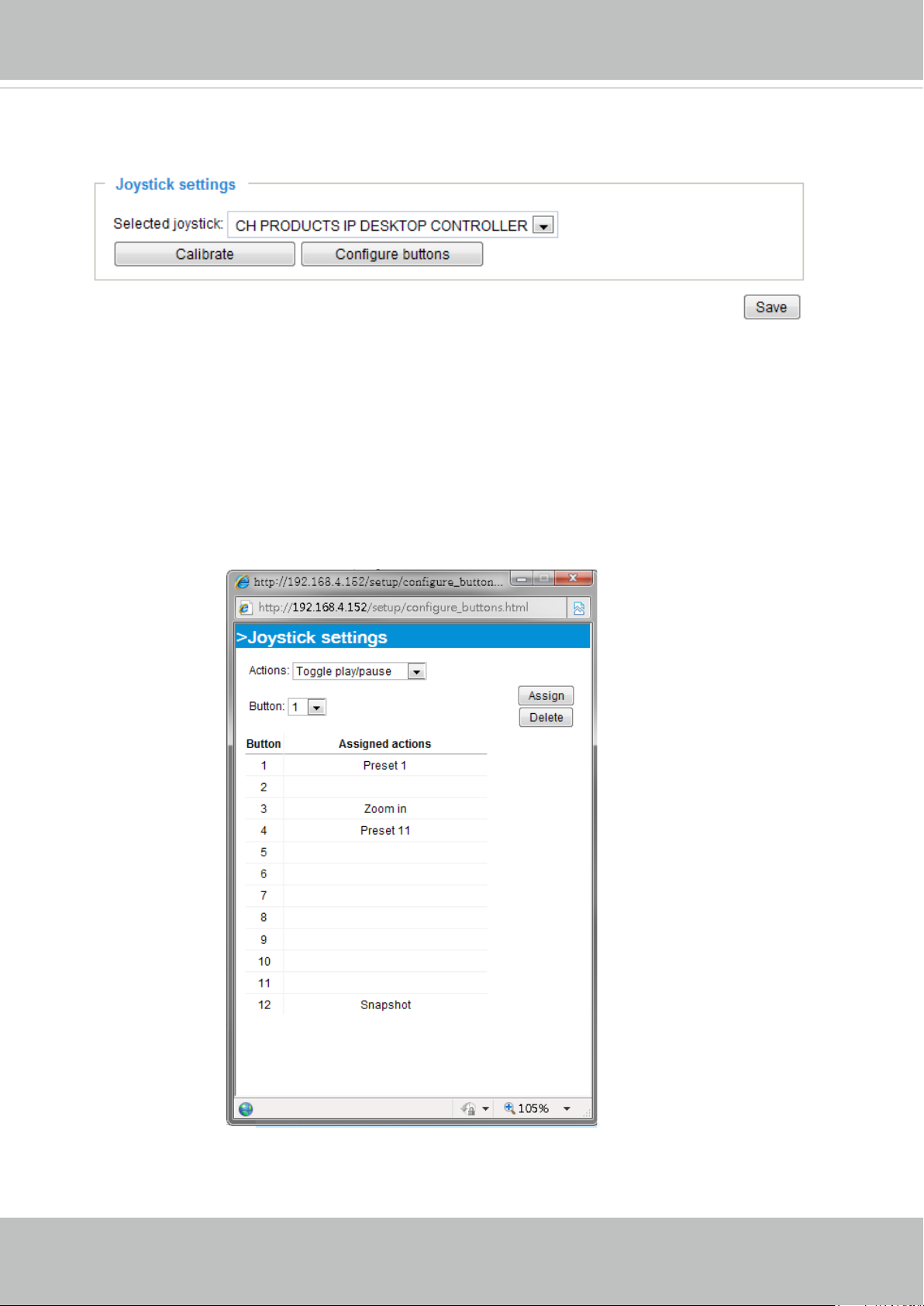
Connect to the USB plug of the joystick to a USB port on your management computer. Once a
USB joystick is connected, the related joystick conguration will be available on the Client settings
window. The joystick should work properly without installing any other driver or software.
Then you can begin to configure the joystick settings of connected devices. Please follow the
instructions below to enable joystick settings.
1. Click on the Congure buttons button. If your joystick is working properly, it will be displayed on
the drop-down list.
User's Manual - 31
Page 32
VIVOTEK
Buttons Conguration
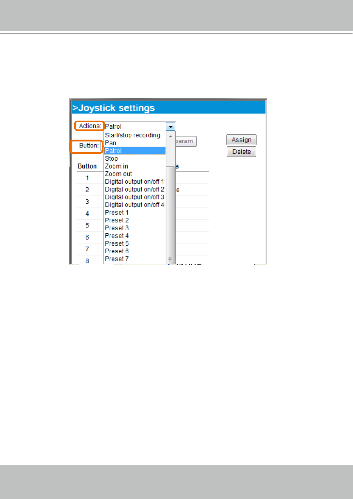
In the Joystick Settings window, you can use the combinations of pull-down menus, Actions and
Button number, to assign joystick buttons with different functions. The number of buttons may differ
from the joystick you attached.
Please follow the steps below to congure your joystick buttons:
1. Select the number of the button you want to congure from its pull-down list.
For example: Assign Preset 1 (move to preset 1 position) to Button 1.
2. Select an action from the Actions menu. Click Assign to associate the button with an action.
3. Your conguration will be automatically saved.
To disable an assignment, select the number of a button, and then click the Delete button. The
4.
associated action will then be cleared.
5. Repeat the above process to assign actions to other buttons.
When done, simply close the
conguration window.
32 - User's Manual
Page 33
VIVOTEK
NOTE:
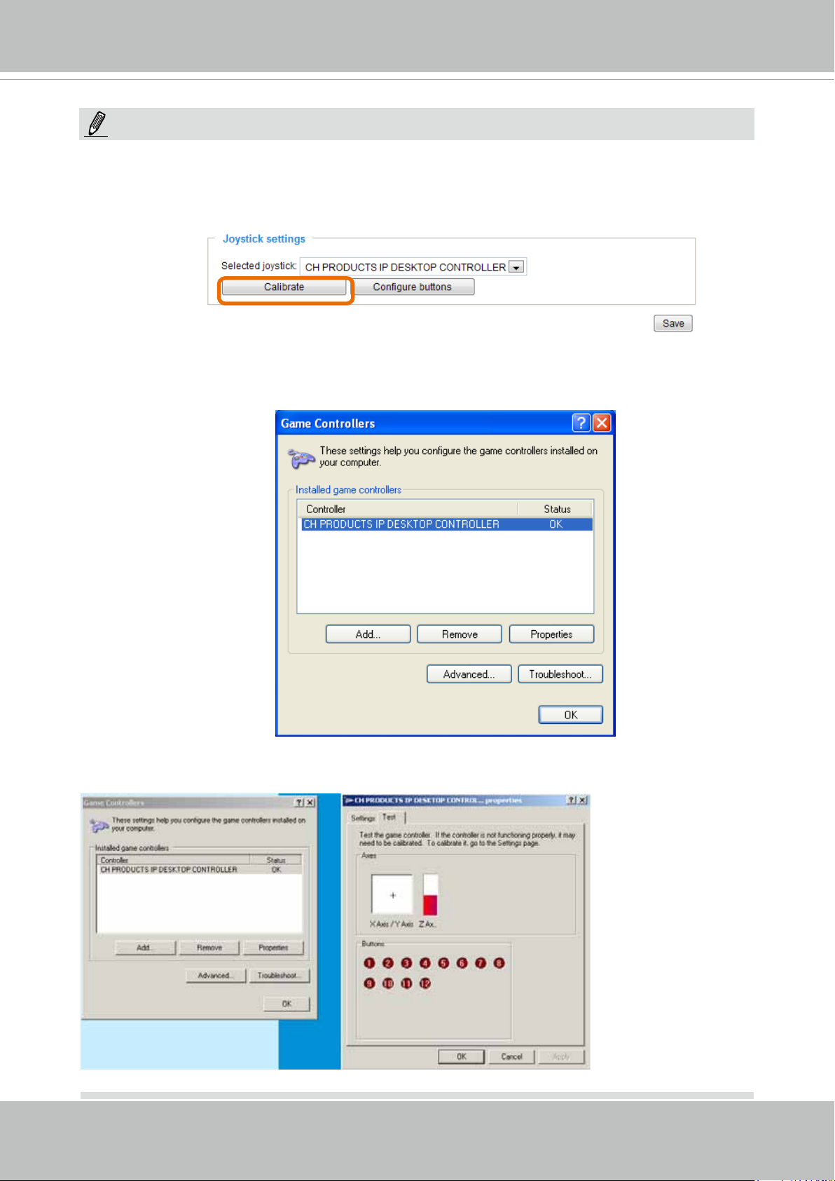
• If you want to assign Preset actions to your joystick, the PTZ preset locations should be congured
in advance.
• If your joystick is not working properly, it may need to be calibrated. Click the Calibrate button to
open the Game Controllers window located in Microsoft Windows control panel and follow the
instructions for trouble shooting.
• The joystick will appear in the Game Controllers list in the Windows Control panel. If you want to
check out for your devices, go to the following page: Start -> Control Panel -> Game Controllers.
• Follow the onscreen instructions to calibrate your joystick.
User's Manual - 33
Page 34
VIVOTEK
Conguration
Click Configuration on the main page to enter the camera setting pages. Note that only
Administrators can access the conguration page.
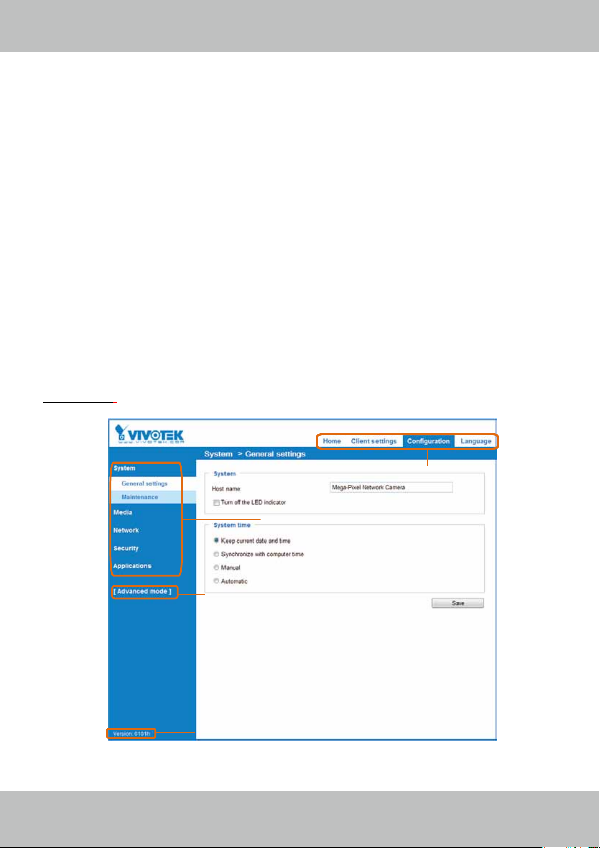
VIVOTEK offers an easy-to-use user interface that helps you set up your network camera with
minimal effort. To simplify the setting procedure, two types of user interfaces are available:
Advanced Mode for professional users and Basic Mode for entry-level users. Some advanced
functions (PTZ/ Event/ Recording/ Local storage) are not displayed in Basic Mode.
If you want to set up advanced functions, please click [Advanced Mode] on the bottom of the
conguration list to quickly switch to Advanced Mode.
In order to simplify the user interface, the detailed information will be hidden unless you click on
the function item. When you click on the rst sub-item, the detailed information for the rst subitem will be displayed; when you click on the second sub-item, the detailed information for the
second sub-item will be displayed and that of the rst sub-item will be hidden.
The following is the interface of the Basic Mode and the Advanced Mode:
Basic Mode
Navigation Area
Configuration List
Click to switch to Advanced Mode
34 - User's Manual
Firmware Version
Page 35
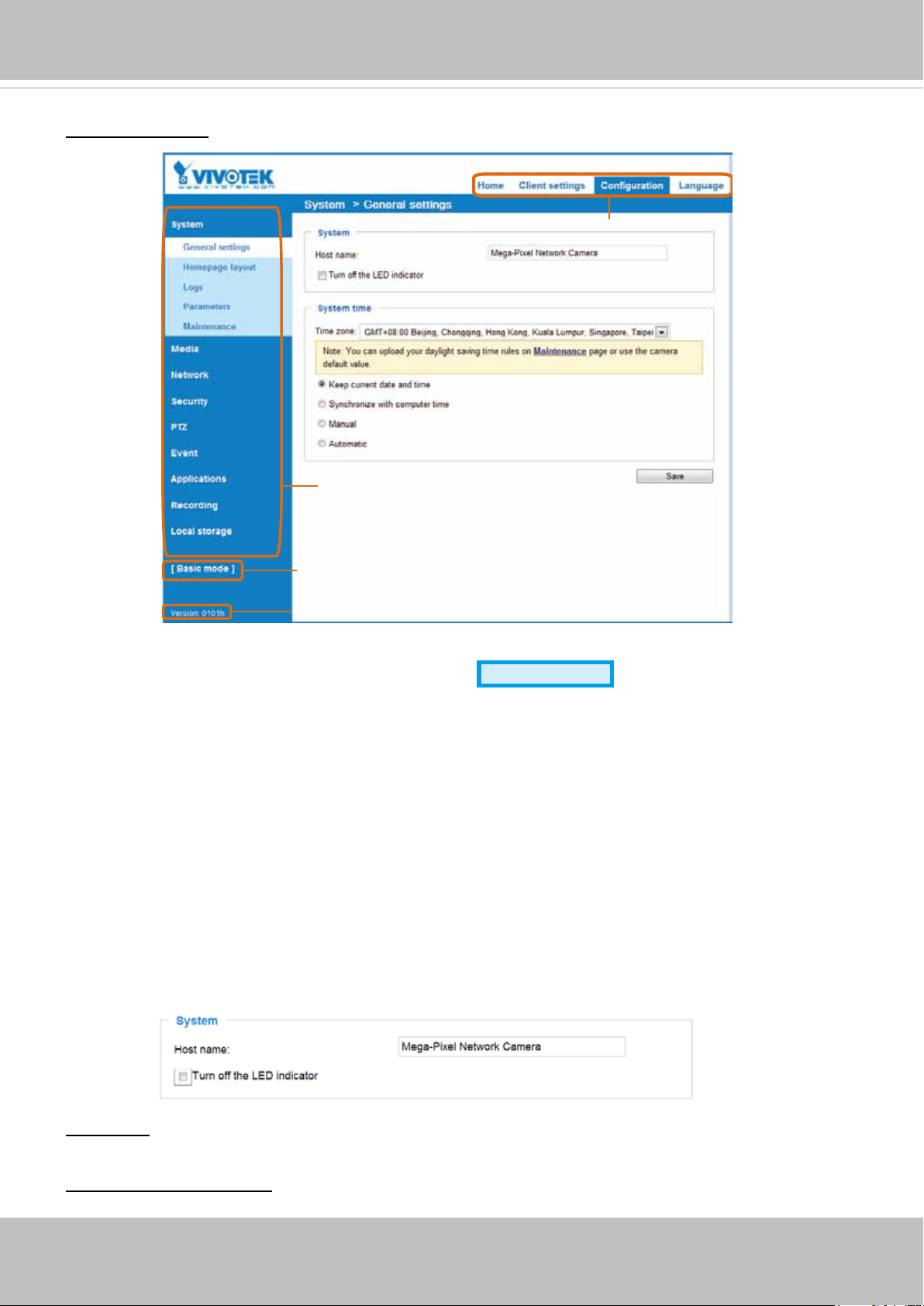
Advanced Mode
VIVOTEK
Navigation Area
Configuration List
Click to switch to Basic Mode
Firmware Version
Each function on the conguration list will be explained in the following sections. Those functions that
are displayed only in Advanced Mode are tagged with
Advanced Mode
. If you want to set up advanced
functions, please click [Advanced Mode] on the bottom of the conguration list to quickly switch over.
Navigation Area provides an instant switch among Home page (the monitoring page for live viewing),
Client settings, Conguration page, and multi-language selection.
System > General settings
This section explains how to congure the basic settings for the Network Camera, such as the
host name and system time. It is composed of the following two columns: System, and System
Time. When finished with the settings on this page, click Save at the bottom of the page to
enable the settings.
System
Host name: Enter a desired name for the Network Camera. The text will be displayed at the top of the
main page, and also on the view cell of ST-7501 and VAST management software.
Turn off the LED indicators: If you do not want others to notice the network camera is in operation, you
can select this option to turn off the LED indicators.
User's Manual - 35
Page 36
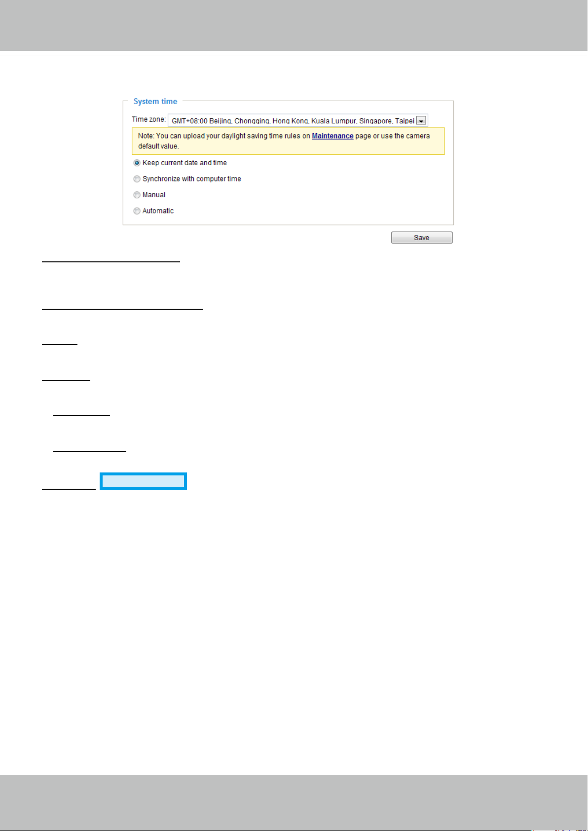
VIVOTEK
System time
Keep current date and time: Select this option to preserve the current date and time of the Network
Camera. The Network Camera’s internal real-time clock maintains the date and time even when the
power of the system is turned off.
Synchronize with computer time: Select this option to synchronize the date and time of the Network
Camera with the local computer. The read-only date and time of the PC is displayed as updated.
Manual: The administrator can enter the date and time manually. Note that the date and time format are
[yyyy/mm/dd] and [hh:mm:ss].
Automatic: The Network Time Protocol is a protocol which synchronizes computer clocks by periodically
querying an NTP Server.
NTP server: Assign the IP address or domain name of the time-server. Leaving the text box blank
connects the Network Camera to the default time servers.
Update interval: Select to update the time using the NTP server on an hourly, daily, weekly, or monthly
basis.
Time zone
Advanced Mode
: Select the appropriate time zone from the list. If you want to upload
Daylight Savings Time rules, please refer to System > Maintenance > Import/ Export les on page 43
for details.
36 - User's Manual
Page 37
VIVOTEK
System > Homepage layout
Advanced Mode
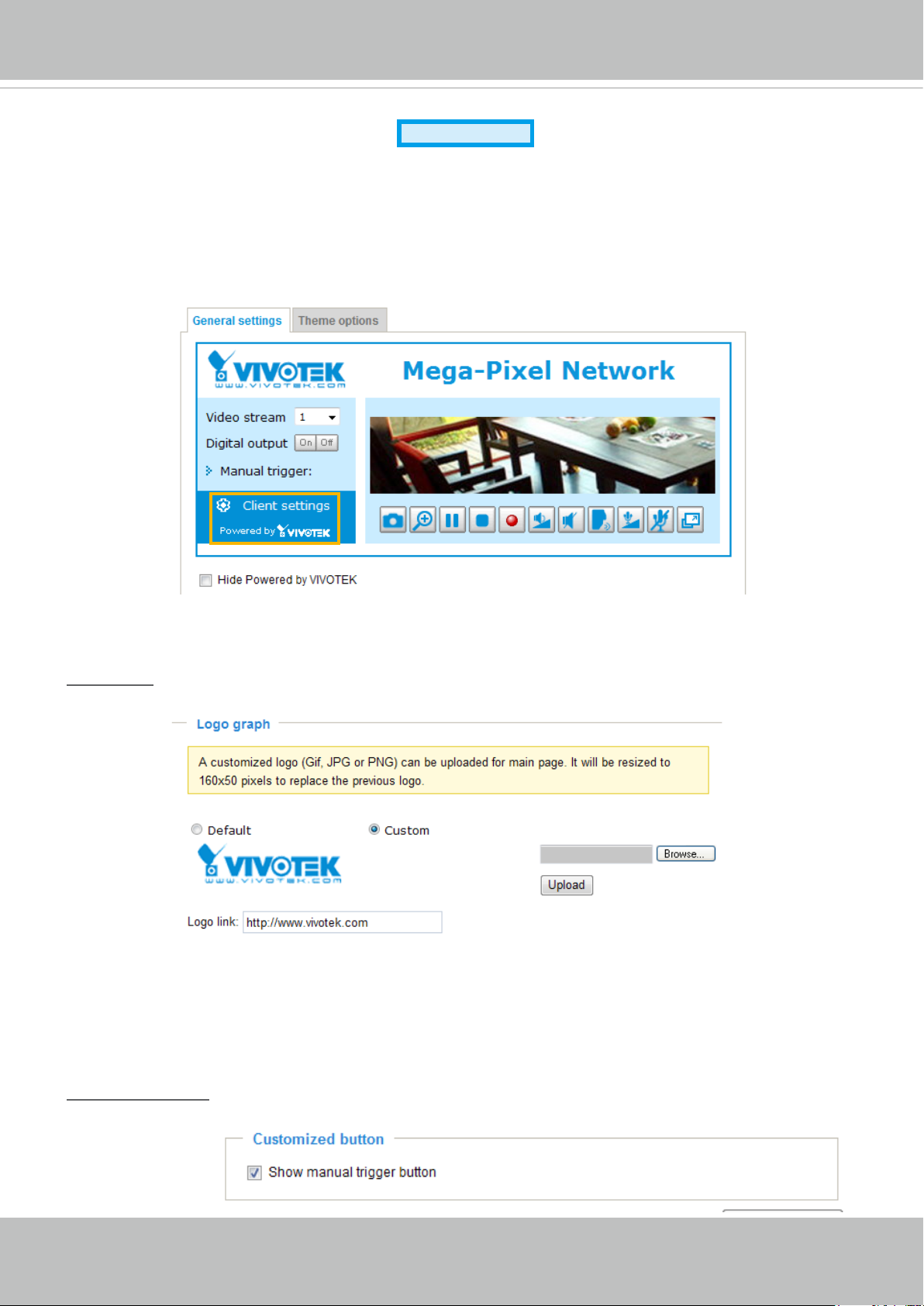
This section explains how to set up your own customized homepage layout.
General settings
This column shows the settings of your hompage layout. You can manually select the background and
font colors in Theme Options (the second tab on this page). The settings will be displayed automatically
in this Preview eld. The following shows the homepage using the default settings:
■ Hide Powered by VIVOTEK: If you check this item, it will be removed from the homepage.
Logo graph
Here you can change the logo at the top of your homepage.
Follow the steps below to upload a new logo:
1. Click Custom and the Browse eld will appear.
2. Select a logo from your les.
3. Click Upload to replace the existing logo with a new one.
4. Enter a website link if necessary.
5. Click Save to enable the settings.
Customized button
If you want to hide manual trigger buttons on the homepage, please uncheck this item. This item is
checked by default.
User's Manual - 37
Page 38
VIVOTEK
Theme Options
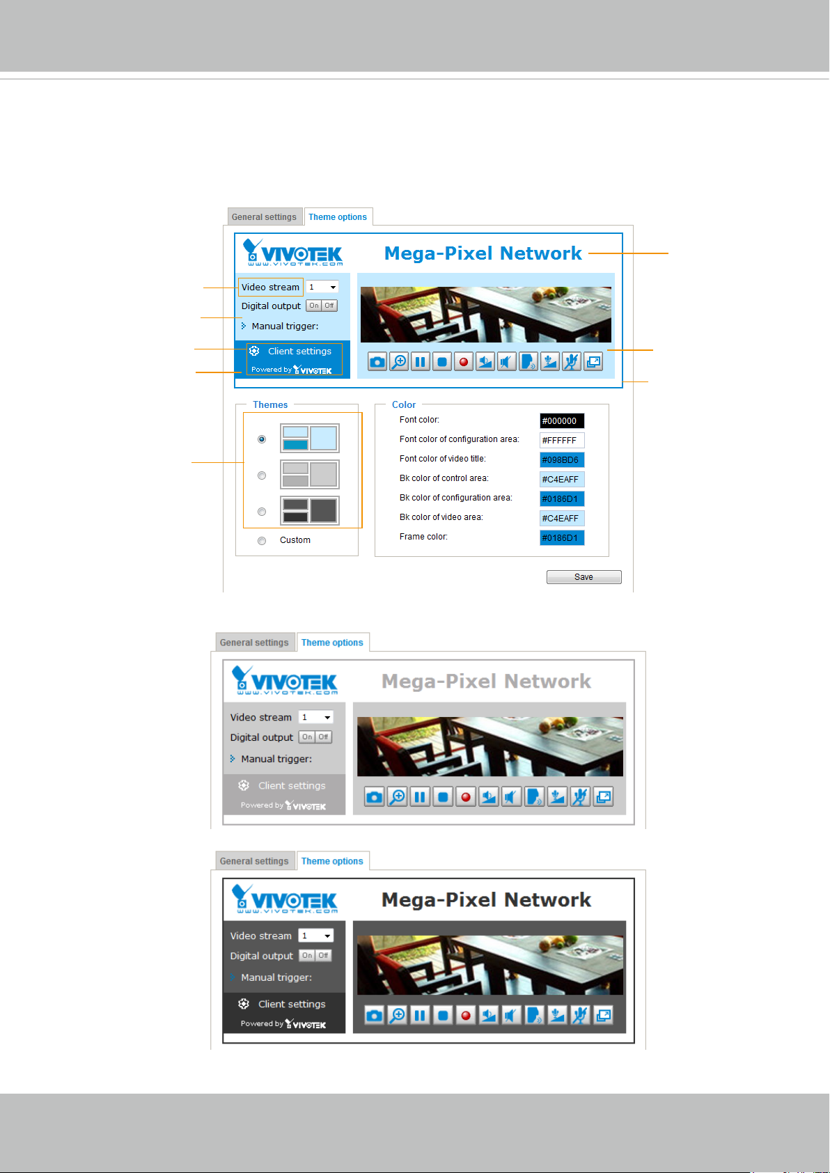
Here you can change the color of your homepage layout. There are three types of preset patterns for you
to choose from. The new layout will simultaneously appear in the Preview led. Click Save to enable the
settings.
Font Color of the
Video Title
Font Color
Background Color of the
Control Area
Font Color of
the Configuration Area
Background Color of the
Configuration Area
Background Color of
the Video Area
Frame Color
Preset patterns
38 - User's Manual
Page 39
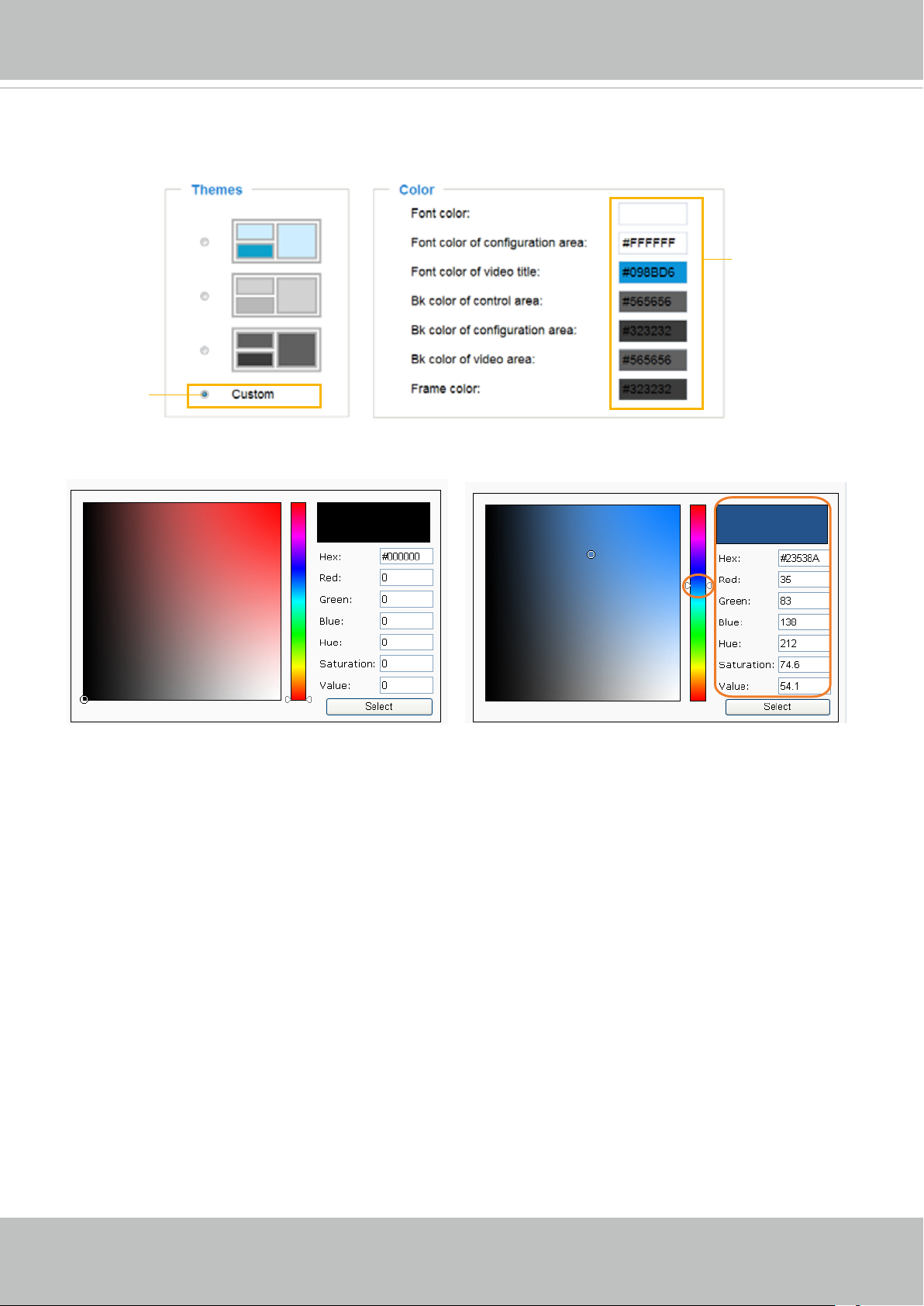
■ Follow the steps below to set up the customized homepage:
1. Click Custom on the left column.
2. Click the eld where you want to change the color on the right column.
Custom
Pattern
3. The palette window will prompt as follows.
VIVOTEK
Color Selector
2
1
4
4. Drag the slider bar and click on the left square to select a desired color.
5. The selected color will be displayed in the corresponding elds and in the Preview column.
6. Click Save to enable the settings.
3
User's Manual - 39
Page 40
VIVOTEK
System > Logs
Advanced Mode
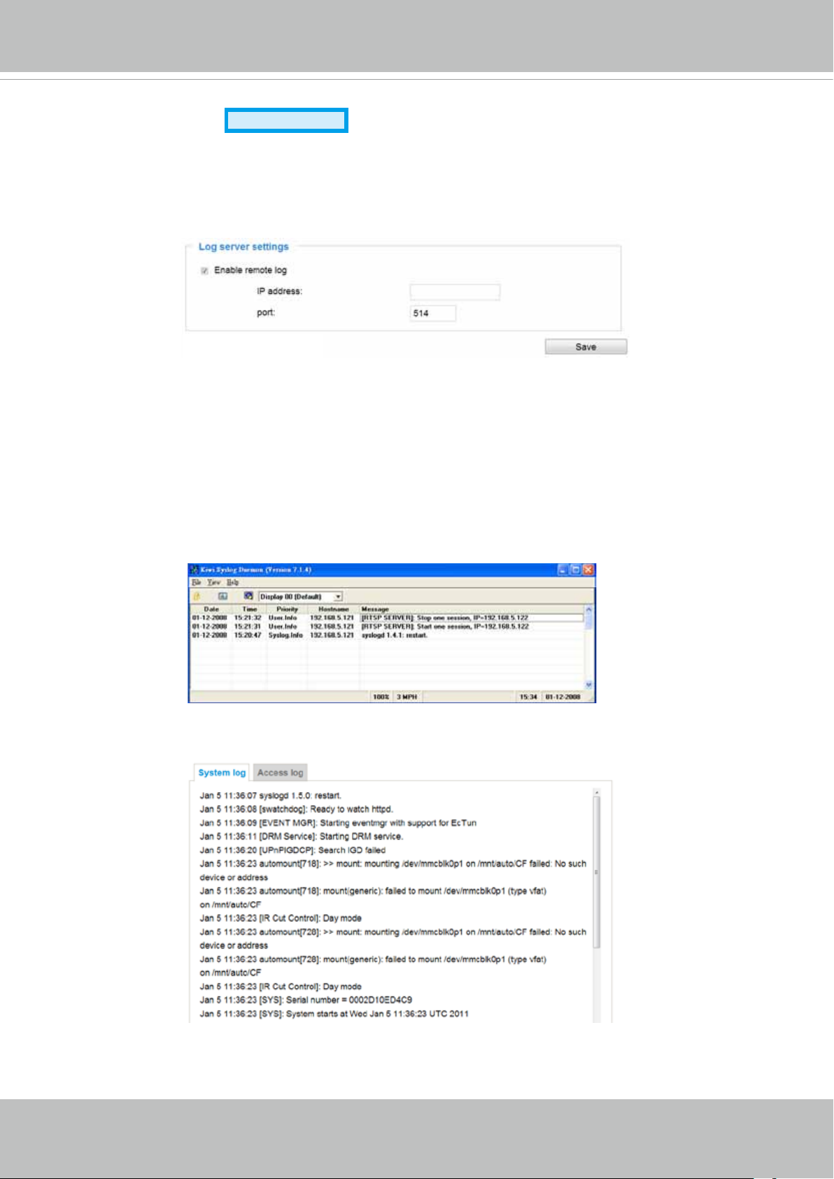
This section explains how to congure the Network Camera to send the system log to a remote
server as backup.
Log server settings
Follow the steps below to set up the remote log:
1. Select Enable remote log.
2. In the IP address text box, enter the IP address of the remote server.
2. In the port text box, enter the port number of the remote server.
3. When completed, click Save to enable the setting.
You can congure the Network Camera to send the system log le to a remote server as a log backup.
Before utilizing this feature, it is suggested that the user install a log-recording tool to receive system log
messages from the Network Camera. An example is Kiwi Syslog Daemon. Visit http://www.kiwisyslog.
com/kiwi-syslog-daemon-overview/.
System log
This column displays the system log in a chronological order. The system log is stored in the Network
Camera’s buffer area and will be overwritten when reaching a certain limit.
40 - User's Manual
Page 41
VIVOTEK
Access log
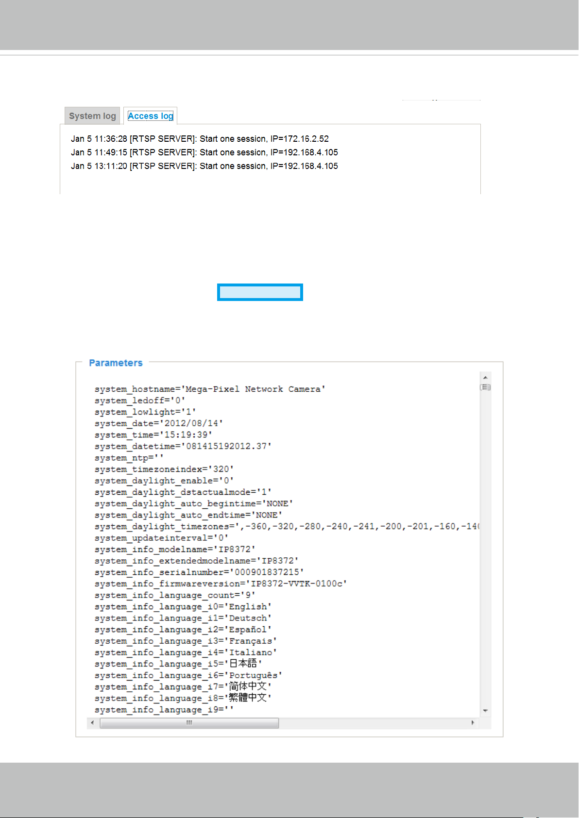
Access log displays the access time and IP address of all viewers (including operators and
administrators) in a chronological order. The access log is stored in the Network Camera’s buffer
area and will be overwritten when reaching a certain limit.
System > Parameters
Advanced Mode
The View Parameters page lists the entire system’s parameters. If you need technical
assistance, please provide the information listed on this page.
User's Manual - 41
Page 42
VIVOTEK
System > Maintenance
This chapter explains how to restore the Network Camera to factory default, upgrade rmware
version, etc.
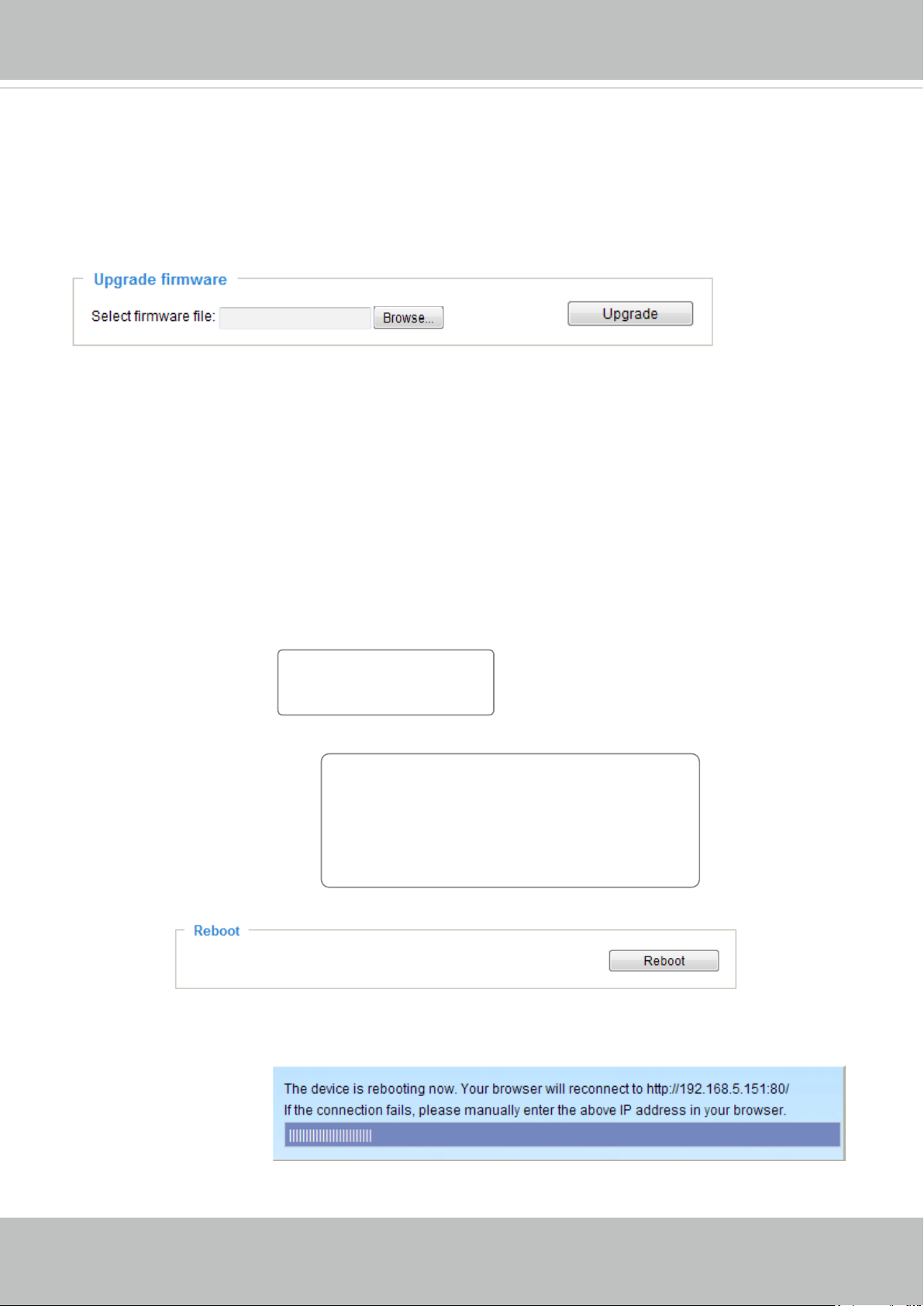
General settings > Upgrade rmware
This feature allows you to upgrade the firmware of your Network Camera. It takes a few minutes to
complete the process.
Note: Do not power off the Network Camera during the upgrade!
Follow the steps below to upgrade the rmware:
1. Download the latest rmware le from the VIVOTEK website. The le is in .pkg le format.
2. Click Browse… and specify the rmware le.
3. Click Upgrade. The Network Camera starts to upgrade and will reboot automatically when the upgrade
completes.
If the upgrade is successful, you will see “Reboot system now!! This connection will close”. After that, re-
access the Network Camera.
The following message is displayed when the upgrade has succeeded.
Reboot system now!!
This connection will close.
The following message is displayed when you have selected an incorrect rmware le.
Starting firmware upgrade...
Do not power down the server during the upgrade.
The server will restart automatically after the upgrade is
completed.
This will take about 1 - 5 minutes.
Wrong PKG file format
Unpack fail
General settings > Reboot
This feature allows you to reboot the Network Camera, which takes about one minute to complete. When
completed, the live video page will be displayed in your browser. The following message will be displayed
during the reboot process.
If the connection fails after rebooting, manually enter the IP address of the Network Camera in the
address eld to resume the connection.
42 - User's Manual
Page 43
VIVOTEK
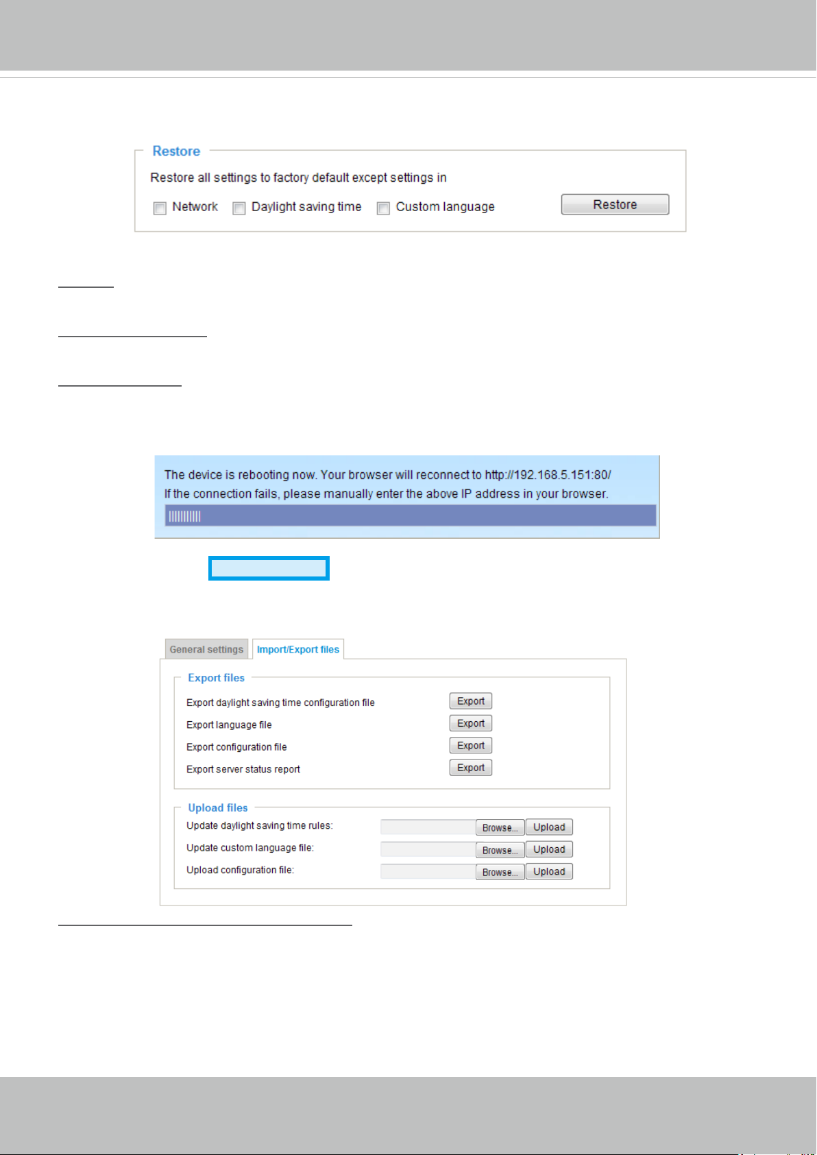
General settings > Restore
This feature allows you to restore the Network Camera to factory default settings.
Network: Select this option to retain the Network Type settings (please refer to Network Type on page
61).
Daylight Saving Time: Select this option to retain the Daylight Saving Time settings (please refer to
Import/Export les below on this page).
Custom Language: Select this option to retain the Custom Language settings.
If none of the options is selected, all settings will be restored to factory default. The following message is
displayed during the restoring process.
Import/Export les
Advanced Mode
This feature allows you to Export / Update daylight saving time rules, custom language le, conguration
le, and server status report.
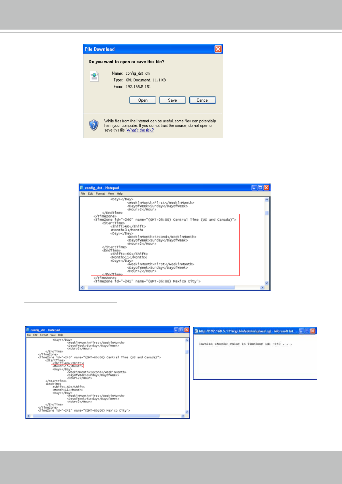
Export daylight saving time conguration le: Click to set the start and end time of DST (Daylight Saving).
Follow the steps below to export:
1. In the Export les column, click Export to export the daylight saving time conguration le from the
Network Camera.
2. A le download dialog will pop up as shown below. Click Open to review the XML le or click Save to
store the le for editing.
User's Manual - 43
Page 44
VIVOTEK
3. Open the le with Microsoft® Notepad and locate your time zone; set the start and end time of DST.
When completed, save the le.
In the example below, DST begins each year at 2:00 a.m. on the second Sunday in March and ends at
2:00 a.m. on the rst Sunday in November.
Update daylight saving time rules: Click Browse… and specify the XML le to update.
If the incorrect date and time are assigned, you will see the following warning message when uploading
the le to the Network Camera.
44 - User's Manual
Page 45
VIVOTEK
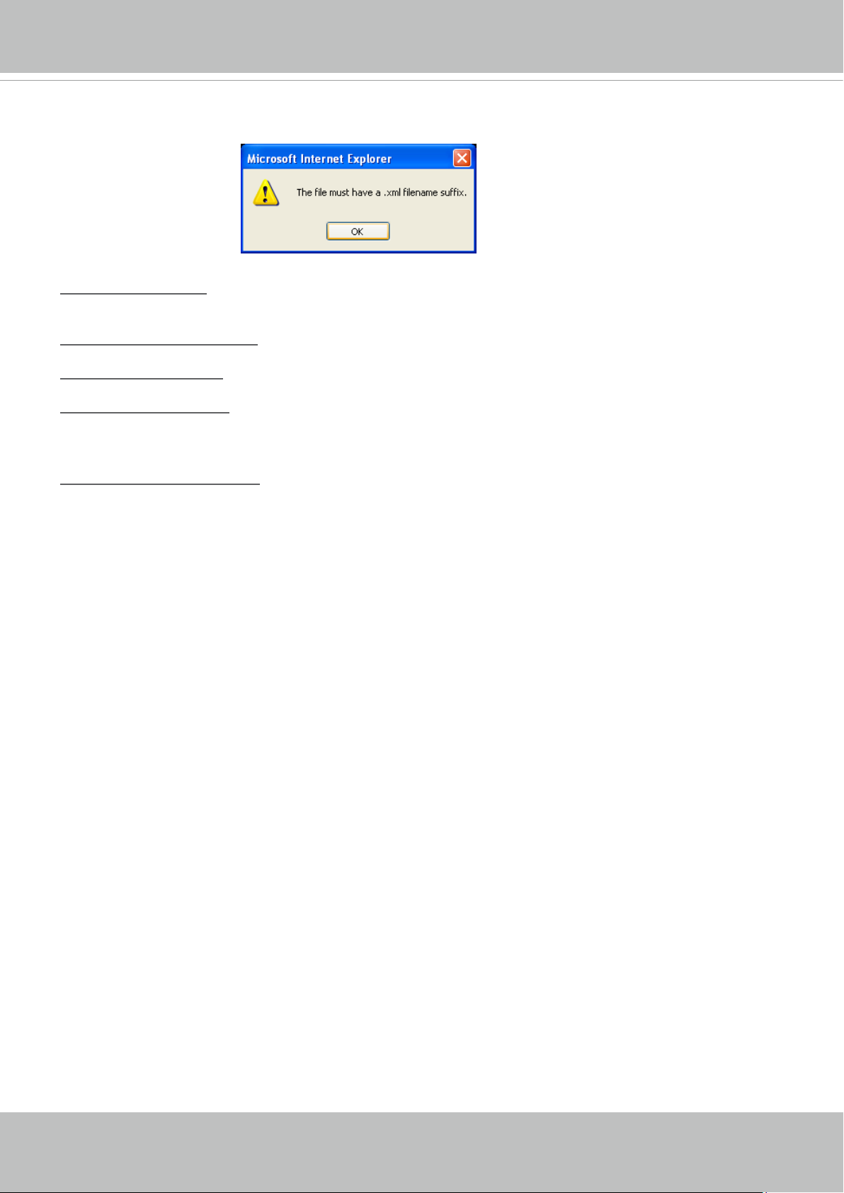
The following message is displayed when attempting to upload an incorrect le format.
Export language file: Click to export language strings. VIVOTEK provides nine languages: English,
Deutsch, Español, Français, Italiano,
日本語,
Português,
簡体中文
, and
繁體中文
.
Update custom language le: Click Browse… and specify your own custom language le to upload.
Export conguration le: Click to export all parameters for the device and user-dened scripts.
Update conguration le: Click Browse… to update a conguration le. Please note that the model and
rmware version of the device should be the same as the conguration le. If you have set up a xed IP
or other special settings for your device, it is not suggested to update a conguration le.
Export server staus report: Click to export the current server status report, such as time, logs,
parameters, process status, memory status, le system status, network status, kernel message ... and so
on.
User's Manual - 45
Page 46
VIVOTEK
Media > Image
Advanced Mode
This section explains how to configure the image settings of the Network Camera. It is
composed of the following four columns: General settings, Picture settings, Exposure, and
Privacy mask.
General settings
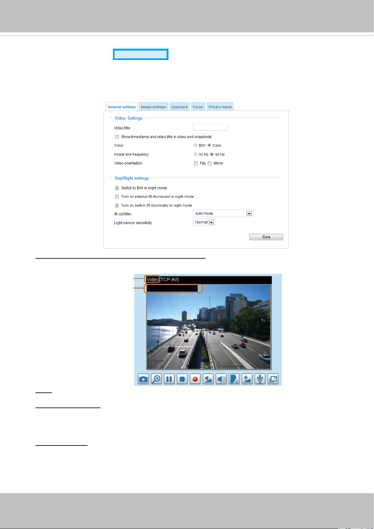
Show timestamp and video title in video and snapshots:
Enter a name that will be displayed on the title bar of the live video as the picture shown below.
Video Title
Title and Time
Video 17:08:56 2012/08/09
2012/08/09 17:08:56
Color: Select to display color or black/white video streams.
Power line frequency: Set the power line frequency consistent with local utility settings to eliminate
image flickering associated with fluorescent lights. Note that after the power line frequency is
changed, you must disconnect and reconnect the power cord of the Network Camera in order for
the new setting to take effect.
Video orientation: Flip--vertically reect the display of the live video; Mirror--horizontally reect the
display of the live video. Select both options if the Network Camera is installed upside-down (ex.
on the ceiling) to correct the image orientation. Please note that the preset locations will be cleared
after ip/mirror.
46 - User's Manual
Page 47
VIVOTEK
Day/Night Settings
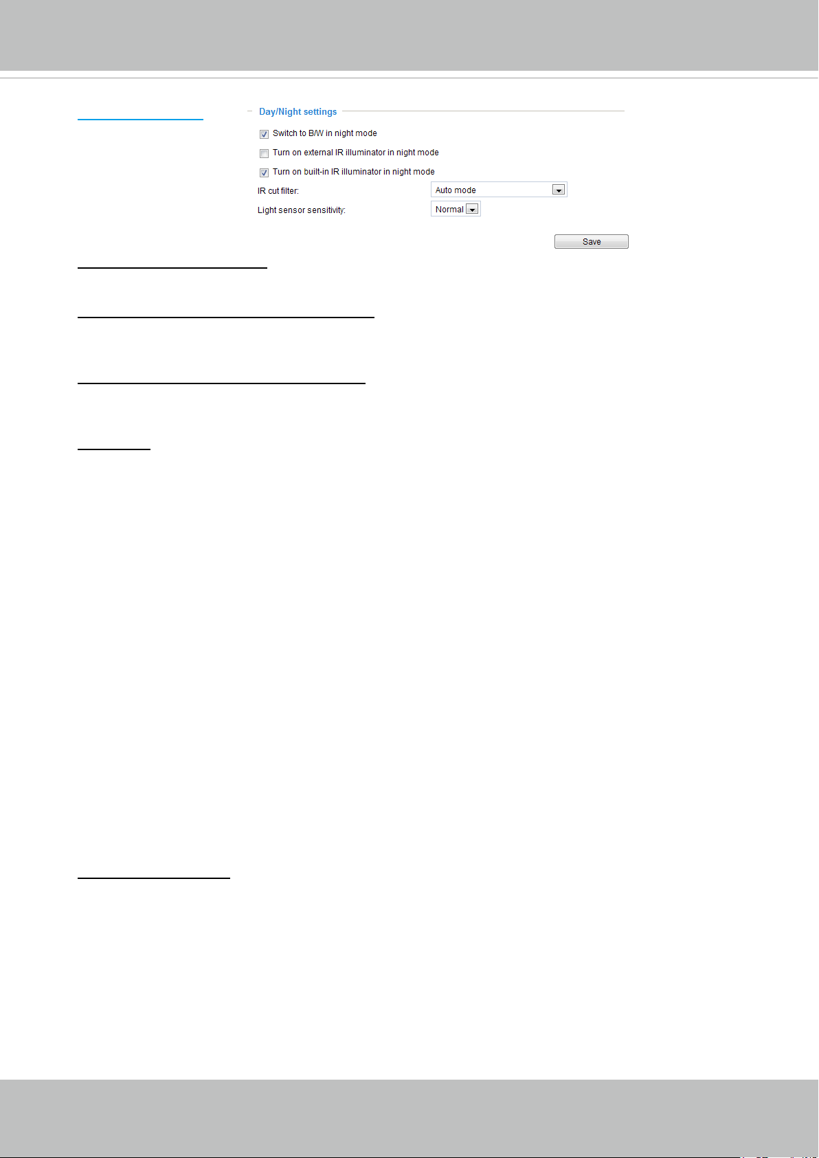
Switch to B/W in night mode
Select this to enable the Network Camera to automatically switch to B/W during night mode.
Turn on external IR illuminator in night mode
Select this to turn on an external IR illuminator (connected via Digital Output lines) when the
camera detects low light condition and enters the night mode.
Turn on built-in IR illuminator in night mode
Select this to turn on the embedded IR illuminators when camera light sensor detects low light
condition and enters the night mode.
IR cut lter
With a removable IR-cut lter, this Network Camera can automatically remove the lter to let IR
light into the sensor during low light conditions.
■ Auto mode
The Network Camera automatically removes the lter by judging the level of ambient light.
■ Day mode
In day mode, the Network Camera switches on the IR cut lter at all times to block infrared light
from reaching the sensor so that the colors will not be distorted.
■ Night mode
In night mode, the Network Camera switches off the IR cut lter at all times for the sensor to
accept infrared light, thus helping to improve low light sensitivity.
■ Synchronize with digital input
The Network Camera automatically removes the IR cut lter when DI triggers. Some external
housing may come with its light sensor and IR lights, and has a pin signal to tell the camera to
switch off its IR cut lter.
■ Schedule mode
The Network Camera switches between day mode and night mode based on a specified
schedule. Enter the start and end time for day mode. Note that the time format is [hh:mm] and is
expressed in 24-hour clock time. By default, the start and end time of day mode are set to 07:00
and 18:00.
Light sensor sensitivity
Select Low, Normal, or High sensitivity for the light sensor.
User's Manual - 47
Page 48
VIVOTEK
Image settings
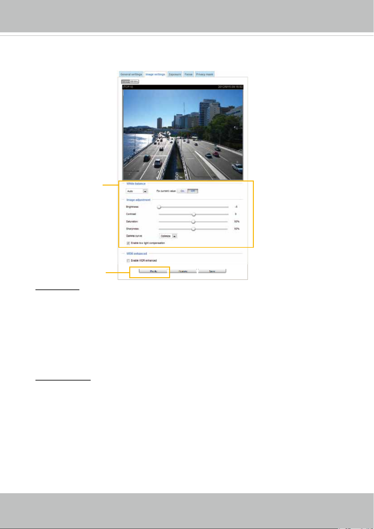
On this page, you can tune the White balance, Image adjustment and WDR enhanced .
Sensor Setting 1:
For normal situations
Sensor Setting 2:
For special situations
White balance: Adjust the value for the best color temperature.
■ Auto: Firmware will automatically adjust the color temperature in the current lighting condition in
response to different light sources.
You may follow the steps below to adjust the white balance to the best color temperature.
1. Set the White balance to Auto.
2. Place a sheet of white paper or a cooler-color (such as blue) in front of the lens, then allow the
Network Camera to automatically adjust the color temperature.
3. Check Fix current value to conrm the setting while the white balance is being measured.
■ Manual: This item allows user to input the R gain & B gain manually.
Image Adjustment
■ Brightness: Adjust the image brightness level, which ranges from -5 to +5.
■ Contrast: Adjust the image contrast level, which ranges from -5 to +5. Please note that this
function will be disabled if you enable WRD enhancement in the column below.
■ Saturation: Adjust the image saturation level, which ranges from -5 to +5. You can also select
Customize and manually enter a value.
■ Sharpness:
Adjust the image sharpness level, which ranges from -3 to +3.
You can also select
Customize and manually enter a value.
■ Gamma curve:
Adjust the image sharpness level, which ranges from
0% to 100%
.
You may let firmware Optimize your display or select the Manual mode, and pull the slide bar
pointer to change the preferred level of Gamma correction towards higher contrast or towards the
48 - User's Manual
Page 49
VIVOTEK
higher luminance for detailed expression for both dark and lighted areas of an image.
■ Enable low light compensation: Select this option in low light mode, and the values of sharpness
and brightness will change automatically. This function also benets from an automated noise
reduction feature.
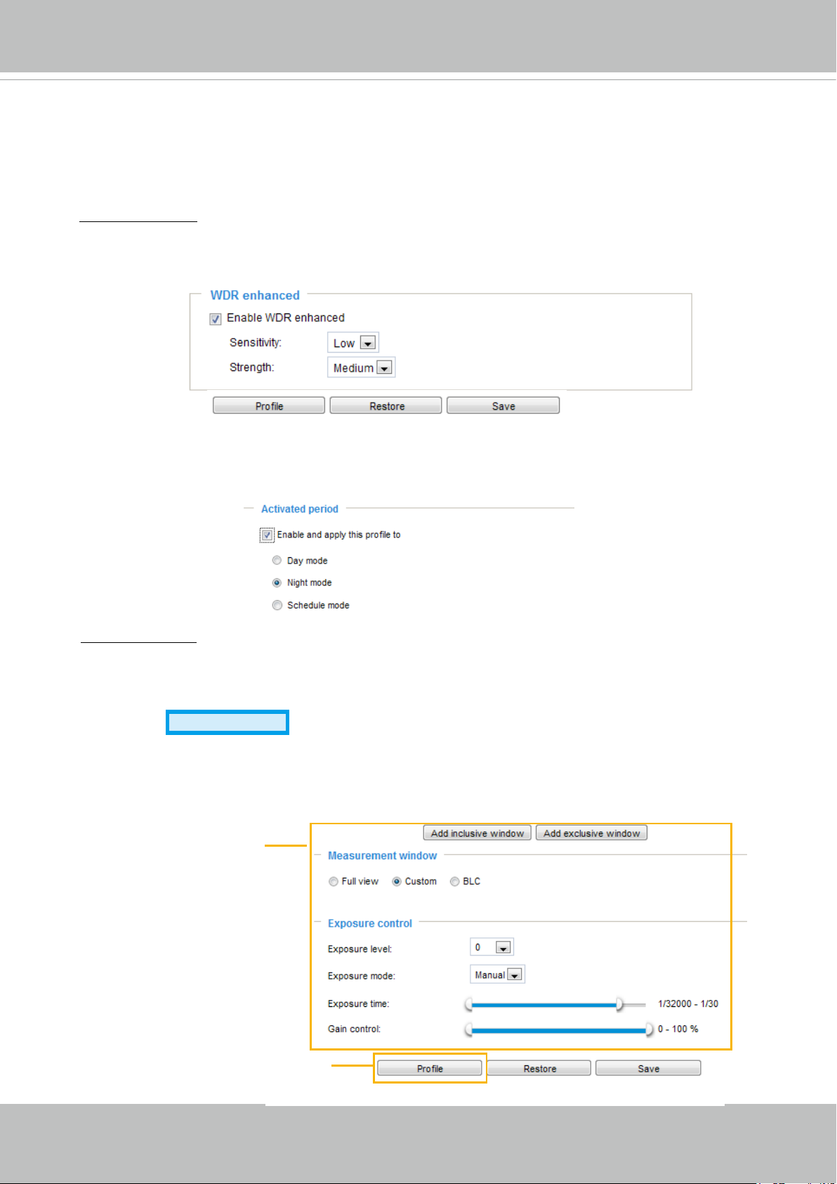
WDR enchanced:
This function allows users to identify more details of objects in the high contrast
environment especially for details in the shaded area. You may check the Enable WDR enhanced
checkbox, and then adjust the sensitivity (low, high) and the strength (low, medium, high) to reach
the best image quality.
Note that the Preview button has been cancelled, all changes made to image settings is directly
shown on screen. You can click Restore to recall the original settings without incorporating the
changes. When completed with the settings on this page, click Save to enable the setting. You can
also click on Prole to adjust all settings above in a pop-up window.
Activated period:
Select the mode this profile to apply to: Day mode, Night mode, or Schedule
mode. Please manually enter a range of time if you choose Schedule mode. Then check Save to
take effect.
Exposure
Advanced Mode
On this page, you can set the Measurement window, Exposure level, Exposure mode, Iris
adjustment, Iris speed, Exposure time, and Gain control settings. Please note that if you set
Exposure Mode to Auto, detailed configurations will be invalidated since the sensor library will
automatically adjust the value according to the ambient light.
Sensor Setting 1:
For normal situations
Sensor Setting 2:
For special situations
User's Manual - 49
Page 50
VIVOTEK
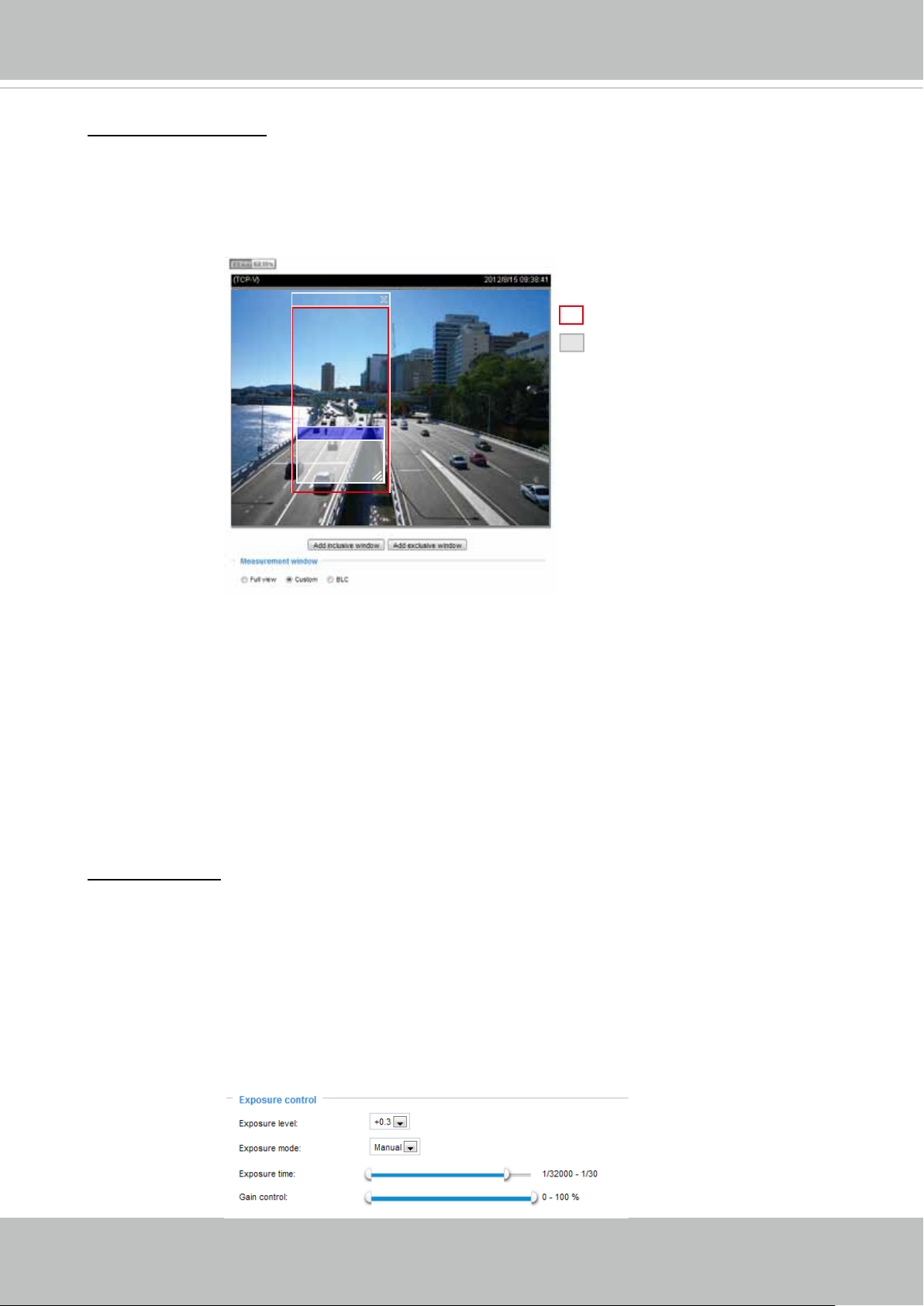
Measurement Window: This function allows user to set measurement window(s) for low light
compesation.
■ Full view: Calculate the full range of view and offer appropriate
light compesation.
■ Custom: This option allows you to manually add customized windows as inclusive or exclusive
regions. A total of 10 windows can be set. The inclusive window refers to “weighted window“; the
exclusive window refers to “ignored window“. It adopts the weighted averages method to calculate
the value.
Include
Exclude x
X
Weighted region
Ignored region
A total of 9 inclusive and exclusive windows can be created for a view. You can create Exclude
windows for the camera to ignore the lighting condition of certain areas.
Note that the title pane of the Include/Exclude windows is not included into the calculation. The
inclusive and exclusive windows can be placed one on top of another. The inclusive windows have a
higher priority. You can overlap these windows, and, if you place an exclusive window within a larger
inclusive window, the exclusive part of the overlapped windows will be deducted from the inclusive
window.
■ BLC: When selected, a BLC window will appear on screen meaning that the center of the scene
will be taken as a weighed area. This option enables light compensation for images that are too
dark or too bright to recognize; for example, for the dark side of objects that is posed against
bright sunlight.
Exposure control:
■
Exposure level: You can manually set the Exposure level, which ranges from -2.0 to +2.0 (dark
to bright). You can click and drag the semi-circular pointers on the Exposure time and Gain
control slide bars to specify a range of shutter time and Gain control values within which the
camera can automatically tune to an optimal imaging result. You may prefer a shorter shutter
time to better capture moving objects, while a faster shutter reduces light and needs to be
compensated by electrical brightness gains.
■
Exposure mode: Select Auto or Manual mode according to your needs.
Manual: Select Manual to set a xed exposure time and gain. Then, tune the slide bar to set the
Exposure time and Gain Control to the best image quality. A shorter exposure time allows less
amount of light to enter the sensor; while a higher gain control value generates certain amount of
noises.
50 - User's Manual
Page 51
VIVOTEK
Auto: If you set Exposure mode as Auto, the Exposure time and Gain control will not be
congurable since the sensor library will automatically adjust the value according to the ambient
light. Then you can congure iris mode as “indoor” or “outdoor” to reach the best image quality.
■ Iris mode:
Select Indoor or Outdoor iris mode to adapt to the installation. The preset iris
aperture setting will apply.
You can click Restore to recall the original settings without incorporating the changes. When
completed with the settings on this page, click Save to enable the settings.
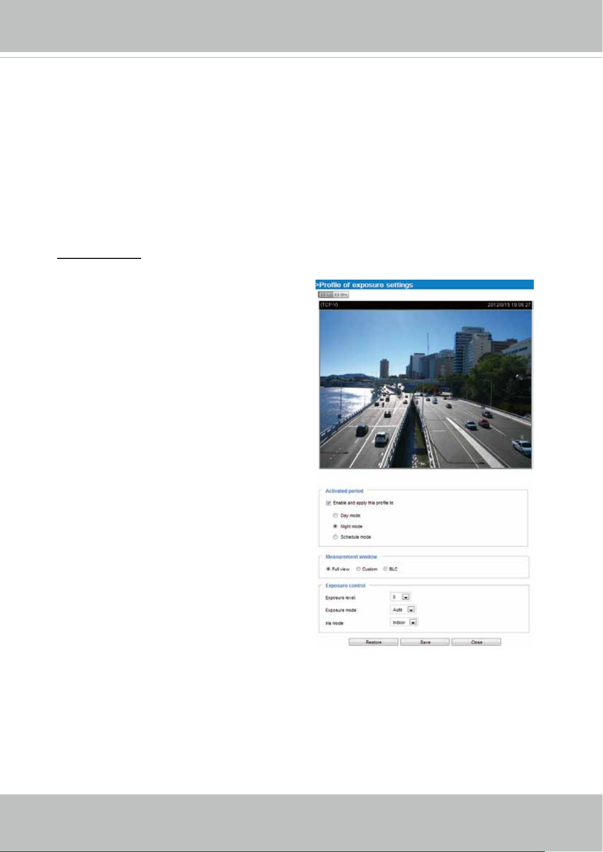
If you want to congure another sensor setting for day/night/schedule mode, please click Prole to
open the Prole of exposure settings page as shown below.
Activated period:
Select the mode this profile to apply to: Day mode, Night mode, or Schedule
mode. Please manually enter a range of time if you choose Schedule mode. Then check Save to
take effect.
Please follow the steps below to setup a prole:
1. Check Enable this prole.
2. Select the applied mode: Day mode, Night
mode, or Schedule mode. Please manually
enter a range of time if you choose Schedule
mode.
3. Configure Exposure control settings in the
folowing columns. Please refer to previous
dicussions for detailed information.
4. Click Save to enable the setting and click Close
to exit the page.
User's Manual - 51
Page 52
VIVOTEK
Focus
Focus, also known as Remote Focus, is applicable to Network Cameras that are equipped
with stepping motor lens. The automated focus adjustment function eliminates the needs
to physically adjust camera focus. In an outdoor deployment consisting of a large number
of cameras, the auto focus function can be very helpful when these cameras become out
of focus after days or weeks of operation. And that can easily result from the effects of
natural forces, e.g., shrink and expand due to a wide range of operating temperatures and
the vibration caused by wind.
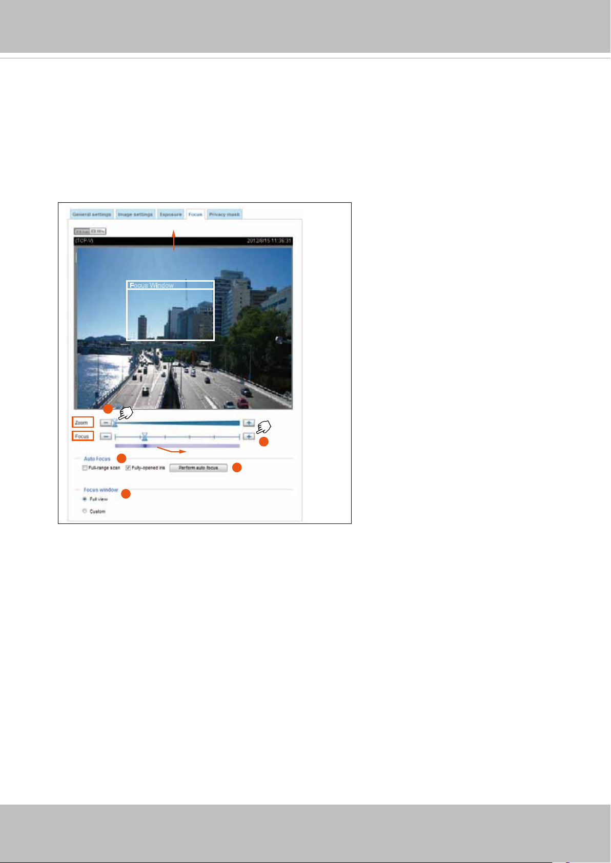
Below is the procedure to perform
Streaming Window
the automated Zoom and Focus
function:
1. Use the Zoom slide bar to find
Focus Window
an optimal view of the area of
interest where you want to adjust
its focus. Click and drag the
double-triangle pointer to rapidly
.
adjust the zoom ratio. The Focus
pointer moves with the Zoom
pointer correspondingly.
1
2. Select from the bottom of the
screen whether you want to
perform focus adjustment on the
5
3
Gradient color bar
4
Full view or within a Custom
focus window. You can create
a custom window and click and
2
drag the window to a desired
position on screen.
3. Click to select the Full-range
scan and/or the Fully-open iris checkboxes. When selected, a full-range scan through
the camera's entire focal length can take about 80 seconds. If not, the auto focus scan
will only go through the length where optimal focus may occur, and that takes about 12
seconds. In theory, best results of the auto scan can be acquired when the camera's iris
is fully open. The iris fully open checkbox is selected by default.
4. Click on the Perform auto focus button, and wait for the scan to complete.
5. After a short while, the clearest image obtained should be displayed and the optimal
focus range is indicated by the densest color area on the color bar. Use the "+" or "-"
button to ne-tune the focus if you are not satised with the results.
The methodology of using the Resize Buttons at the upper left corner of the streaming
window is the same as that on the home page.
52 - User's Manual
Page 53
VIVOTEK
Privacy mask
Advanced Mode
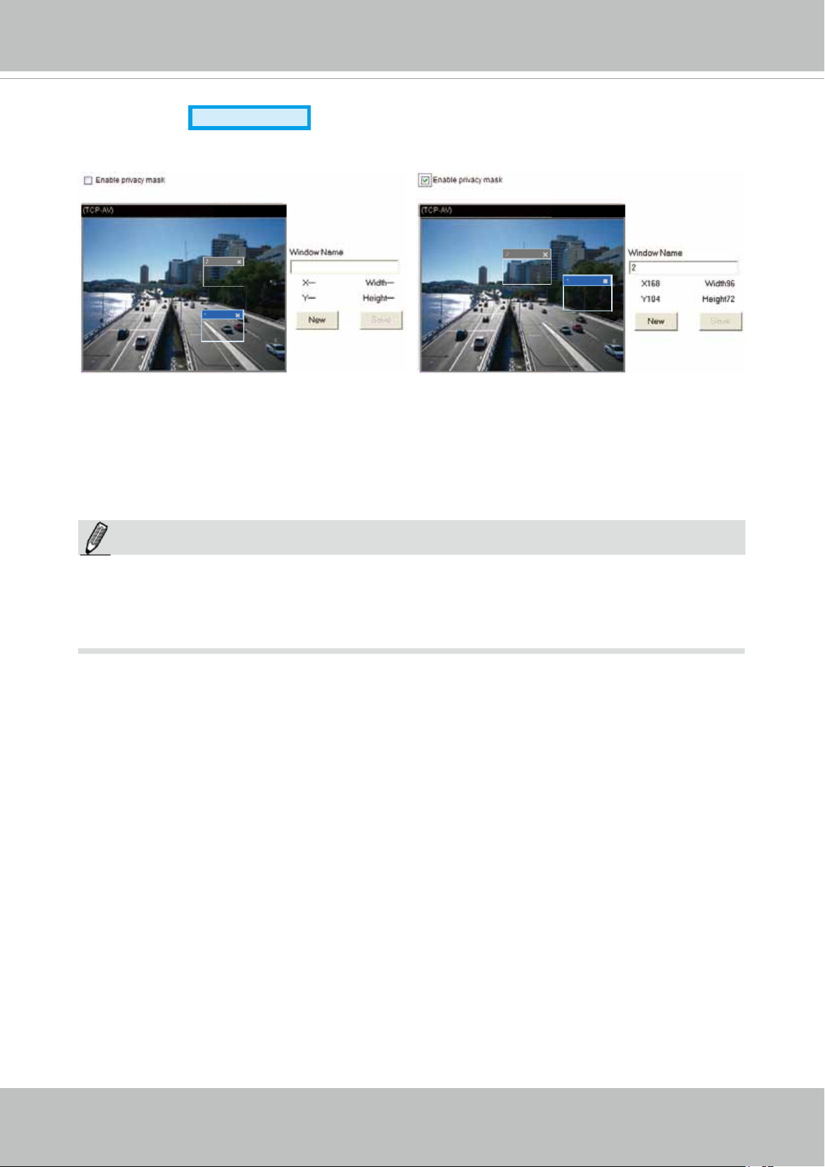
Click Privacy Mask to open the settings page. On this page, you can block out sensitive zones to
address privacy concerns.
2010/12/09 17:08:562010/12/09 17:08:56
■ To set the privacy mask windows, follow the steps below:
1. Click New to add a new window.
2. You can use the mouse cursor to size and drag-drop the window, which is recommended to be
at least twice the size of the object (height and width) you want to cover.
3. Enter a Window Name and click Save to enable the setting.
4. Check Enable privacy mask to enable this function.
NOTE:
NOTE
Up to 5 privacy mask windows can be set up on the same screen.
►
► If you want to delete the
privacy mask
window, please click the ‘x’ on the upper right corner of
the window.
User's Manual - 53
Page 54
VIVOTEK
Media > Video
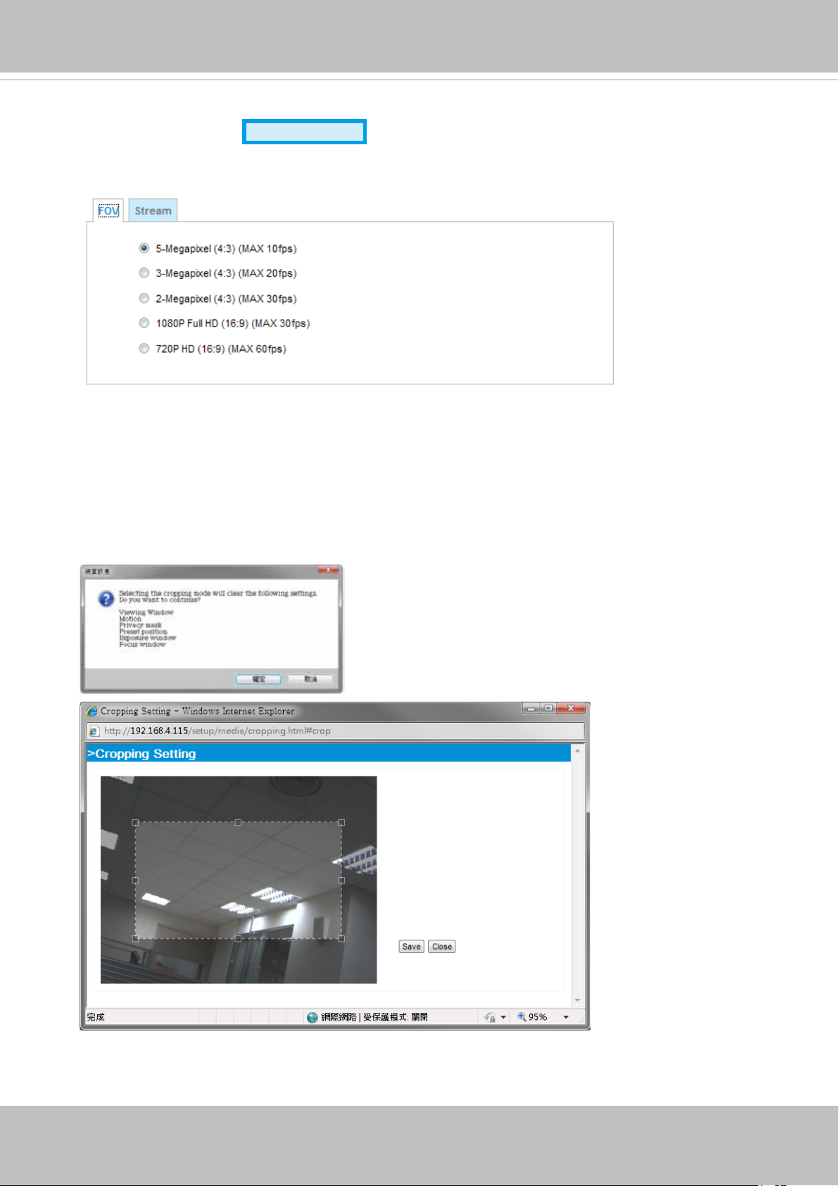
FOV (Field of View)
Select a resolution from the list. The default is 5 Megapixels, and if bandwidth or frame rate per
second is of the concern you can select a lower resolution. The congurable options are: 5MP (4:3)
at 10fps, 3MP (4:3) 20fps, 2MP (4:3) 30fps, 1080P (16:9) 30fps, and 720P (16:9) at 60fps.
Cropping Setting:
When you select a resolution other than the default maximum 5MP, a Cropping Setting window will
prompt. You then need to place the cropped window on a place of your interest by dragging it over
the eld of view. Note that you CAN NOT enlarge or shrink the cropping window. When done with
selecting the eld of view, click Save to preserve your setting and click Close to end the process.
Advanced Mode
Note that the changes in cropping setting will erase
the previous setting with Viewing window, motion
detection, privacy mask, preset positions, etc.
54 - User's Manual
Page 55
VIVOTEK
Stream settings
Advanced Mode
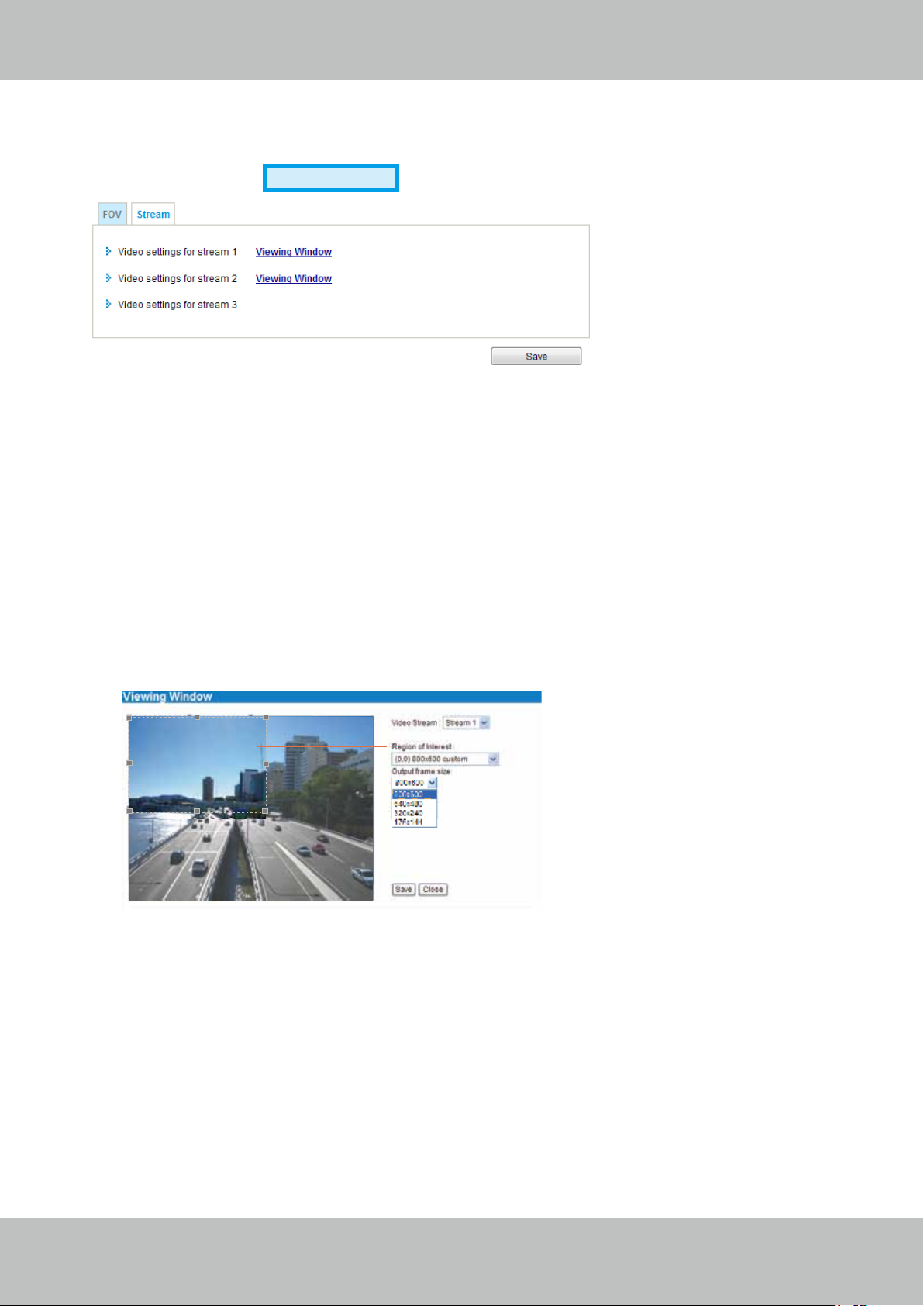
This Network Camera supports multiple streams with frame sizes ranging from 176 x 144 to 2560 x
1920.
The denition of multiple streams:
■ Stream 1: Users can dene the "Region of Interest" (viewing region) and the "Output Frame size"
(size of the live view window).
■ Stream 2: Users can dene the "Region of Interest" (viewing region) and the "Output Frame size"
(size of the live view window).
■ Stream 3: A separately-coingured viewing window is not available for stream #3.
Click Viewing Window to open the viewing region settings page. On this page, you can set the
Region of Interest and the Output Frame Size for stream 1 and 2.
Please follow the steps below to set up those settings for a stream:
1. Select a stream for which you want to set up the viewing region.
2. Select a Region of Interest from the drop-down list. The oating frame, the same as the one
in the Gloabl View window on the home page, will resize accordingly. If you want to set up a
customized viewing region, you can also resize and drag the oating frame to a desired position
with your mouse.
3. Choose a proper Output Frame Size from the drop-down list according to the size of your
monitoring device.
User's Manual - 55
Page 56
VIVOTEK
NOTE:
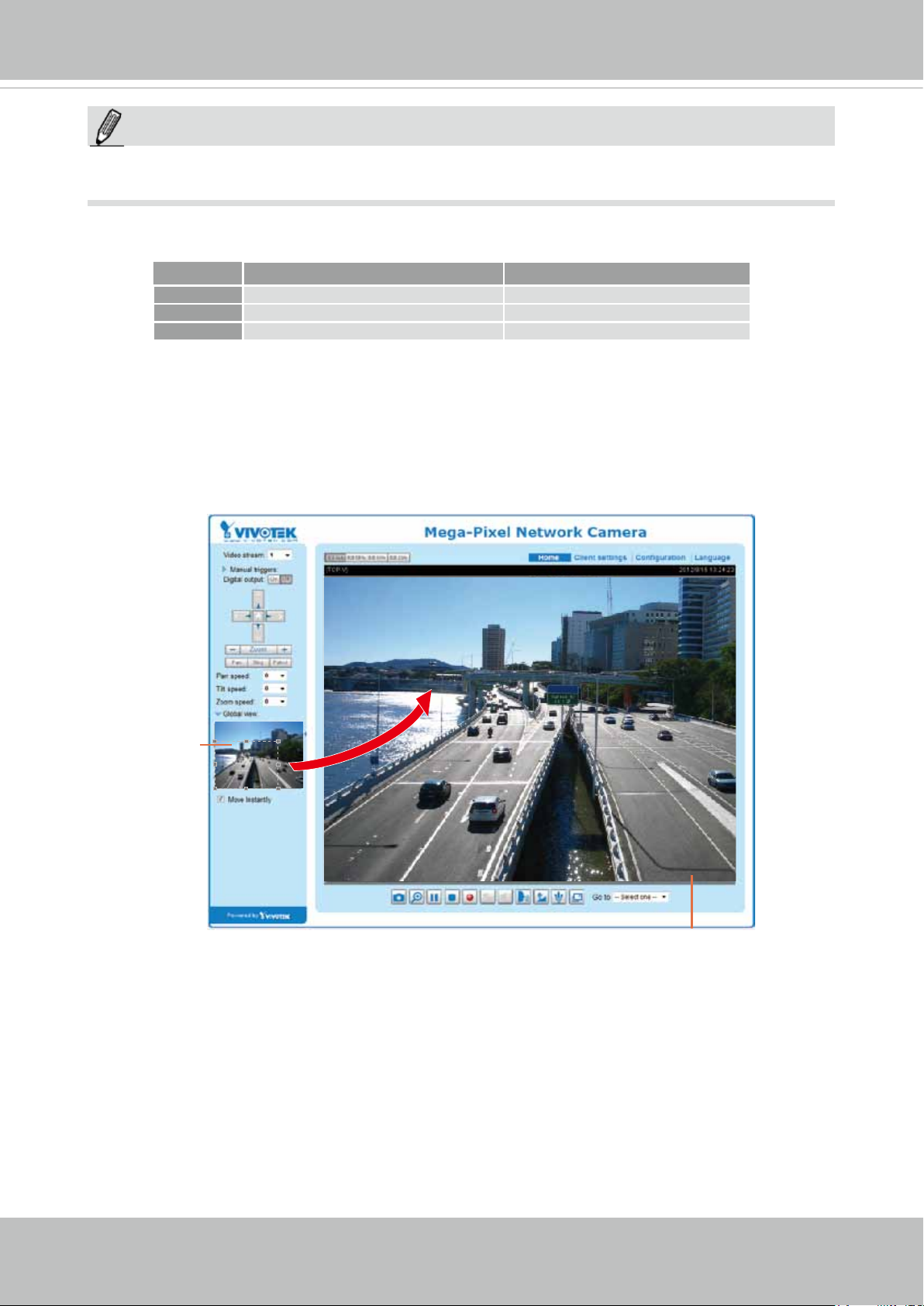
► All the items in the “Region of Interest” should not be larger than the “Output Frame Size“
(current maximum resolution).
■ The parameters of the multiple streams:
Region of Interest Output frame size
Stream 1 2560 X1920 ~ 176 x 144 (Selectable) 2560 X1920 ~176 x 144 (Selectable)
Stream 2 2560 X1920 ~176 x 144 (Selectable) 2560 X1920 ~ 176 x 144 (Selectable)
Stream 3 2560 X1920 (Fixed) 2560 X1920 ~ 176 x 144 (Selectable)
When completed with the settings in the Viewing Window, click Save to enable the settings and
click Close to exit the window. The selected Output Frame Size will immediately be applied to
the Frame size of each video stream. Then you can go back to the home page to test the e-PTZ
function. For more information about the e-PTZ function, please refer to page 92.
Region of Interest
(Viewing Region)
Output Frame Size
(Size of the Live View Window)
56 - User's Manual
Page 57
VIVOTEK
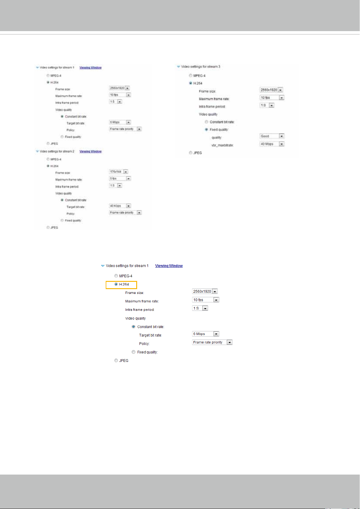
Click the stream setting to display the detailed information. The maximum frame size will follow
your settings in the above Viewing Window sections.
This Network Camera offers real-time H.264, MPEG-4 and MJEPG compression standards (Triple
Codec) for real-time viewing. If H.264 / MPEG-4 mode is selected, the video is streamed via RTSP
protocol. There are several parameters for you to adjust the video performance:
■ Frame size
You can set up different video resolution for different viewing devices. For example, set a smaller
frame size and lower bit rate for remote viewing on mobile phones and a larger video size and
a higher bit rate for live viewing on web browsers. Note that a larger frame size takes up more
bandwidth. By default, stream #2 is down-sized to 176x144 for monitoring on hand-held devices.
■ Maximum frame rate
This limits the maximum refresh frame rate per second. Set the frame rate higher for smoother
video quality and for recognizing moving objects in the eld of view.
If the power line frequency is set to 50Hz, the frame rates are selectable at 1fps, 2fps, 3fps, 5fps,
8fps, 10fps, 15fps, 20fps, and 25fps. If the power line frequency is set to 60Hz, the frame rates
are selectable at 1fps, 2fps, 3fps, 5fps, 8fps, 10fps, 15fps, 20fps, 25fps, and 30fps. You can also
select Customize and manually enter a value.
At the 5 Megpixel mode, the highest frame rate is 10fps. And the 30fps is available when down-
sized to 2 Megapixel mode.
User's Manual - 57
Page 58

VIVOTEK
The frame rate will decrease if you select a higher resolution.
■ Intra frame period
Determine how often to plant an I frame. The shorter the duration, the more likely you will get
better video quality, but at the cost of higher network bandwidth consumption. Select the intra
frame period from the following durations: 1/4 second, 1/2 second, 1 second, 2 seconds, 3
seconds, and 4 seconds.
■
Video quality
Constant bit rate:
• Constant bit rate: A complex scene generally produces a larger le size, meaning that
higher bandwidth will be needed for data transmission. The bandwidth utilization is
congurable to match a selected level, resulting in mutable video quality performance.
The bit rates are selectable at the following rates:
64Kbps, 128Kbps, 256Kbps, 512Kbps, 768Kbps, 1Mbps, 2Mbps, 3Mbps, 4Mbps, 6Mbps,
8Mbps, 10Mbps, 12Mbps, 14Mbps, 16Mbps, 18Mbps, and 20Mbps
20Kbps, 30Kbps, 40Kbps, 50Kbps,
. You can also select
Customize and manually enter a value.
- Target bit rate: select a bit rate from the pull-down menu. The bit rate ranges
from 20kbps to a maximum of 20Mbps. The bit rate then can be a limiting factor for
controlling the quality and the bandwidth consumed for transmitting this video stream.
This bit rate restriction method is particularly useful when planning a conguration
consisting of numerous cameras where video streams can produce high demands
both on network bandwidth and storage space. For example, storing a 6Mbps stream
for 24 hours requires a 63GB disk space. The Network Camera will strive to deliver
video streams within the bit rate limitation you impose.
- Policy: If Frame Rate Priority is selected, the Network Camera will try to maintain
the frame rate per second performance, while image quality will be compromised. If
Image quality priority is selected, the Network Camera may drop some video frames
in order to maintain image quality.
• Fixed quality: On the other hand, if Fixed quality is selected, all frames are
transmitted with the same quality; bandwidth utilization is therefore unpredictable. If
Fixed quality is selected, frame rate performance will be compromised.
- Quality: You can select the following quality options - Medium, Standard,
Good, Detailed, and Excellent. The image quality will then be determined by the
compression rate. For example, a lower quality means a higher compression rate.
The higher the compression rate, the higher the possibility of image distortion, etc.
You can also select Customize and manually enter a logical value from 0 to 51.
- Maximum bit rate: With the guaranteed image quality, you might still want to place
a bit rate limitation to control the size of video streams for bandwidth and storage
concerns. The congurable bit rate starts from 1Mbps to 40Mbps.
You may also manually enter a bit rate number by selecting the Customized option.
If JPEG mode is selected, the Network Camera continuously sends JPEG images to the client,
producing a moving effect similar to a lmstrip. Every single JPEG image transmitted guarantees
the same image quality, which in turn comes at the expense of variable bandwidth usage. Because
the media contents are a combination of JPEG images, no audio data is transmitted to the client.
There are three parameters provided in MJPEG mode to control the video performance:
58 - User's Manual
Page 59
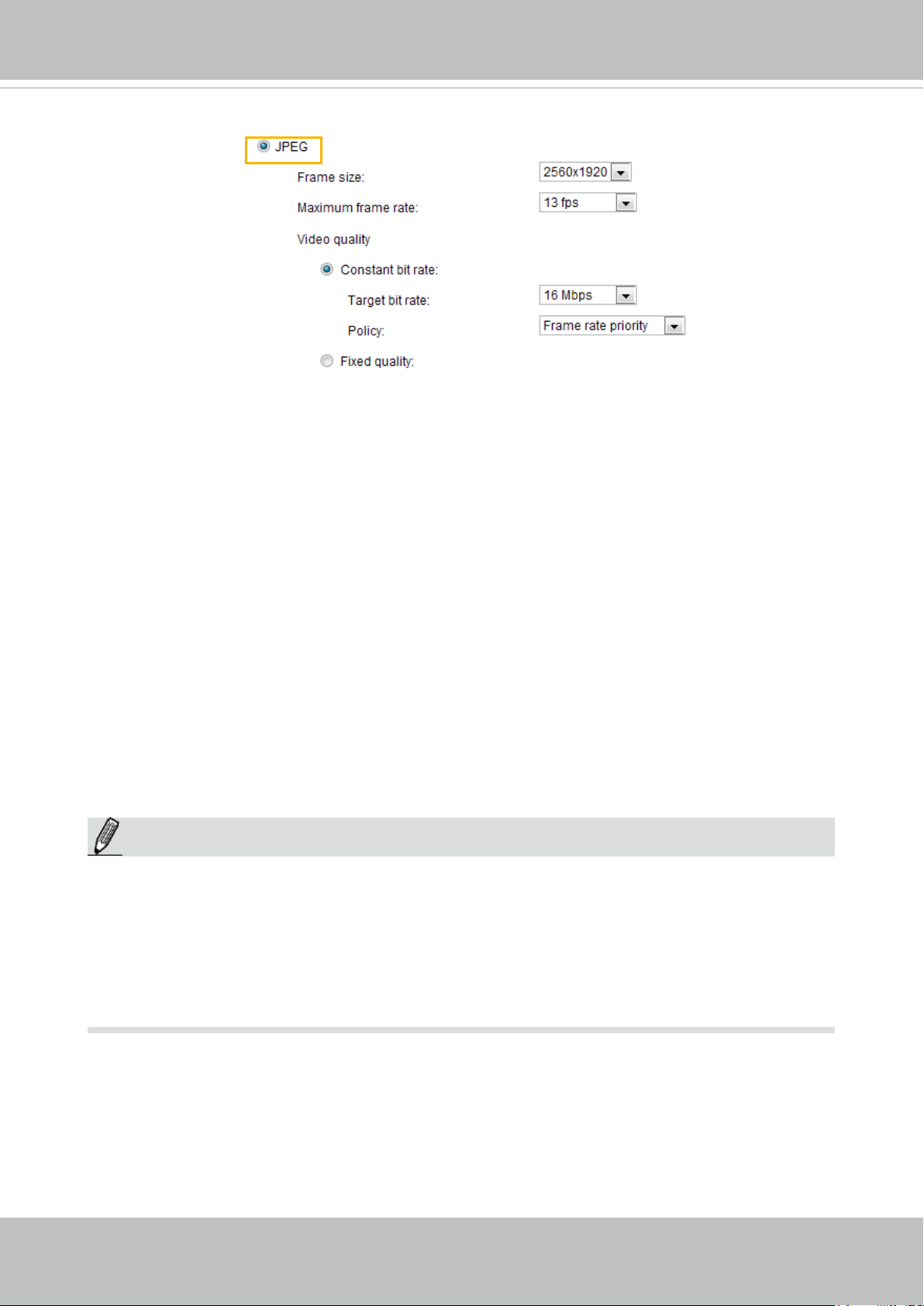
VIVOTEK
■ Frame size
You can set up different video resolution for different viewing devices. For example, set a smaller
frame size and lower bit rate for remote viewing on mobile phones and a larger video size and
a higher bit rate for live viewing on web browsers. Note that a larger frame size takes up more
bandwidth.
■ Maximum frame rate
This limits the maximum refresh frame rate per second. Set the frame rate higher for smoother
video quality.
If the power line frequency is set to 50Hz, the frame rates are selectable at 1fps, 2fps, 3fps, 5fps,
8fps, 10fps, 15fps, 20fps, and 25fps. If the power line frequency is set to 60Hz, the frame rates
are selectable at 1fps, 2fps, 3fps, 5fps, 8fps, 10fps, 15fps, 20fps, 25fps, and 30fps. You can also
select Customize and manually enter a value. The frame rate will decrease if you select a higher
resolution.
■ Video quality
The video quality can be adjusted to the following settings: Medium, Standard, Good, Detailed,
and Excellent. You can also select Customize and manually enter a value. Please refer to the
description in H.264 mode on the previous page for more details.
NOTE:
NOTE
Video quality and xed quality refers to the compression rate, so a lower value will produce higher
►
quality.
►
Converting high-quality video may signicantly increase the CPU loading, and you may encounter
streaming disconnection or video loss while capturing a complicated scene. In the event of
occurance, we suggest you customize a lower video resolution or reduce the frame rate to obtain
smooth video.
User's Manual - 59
Page 60
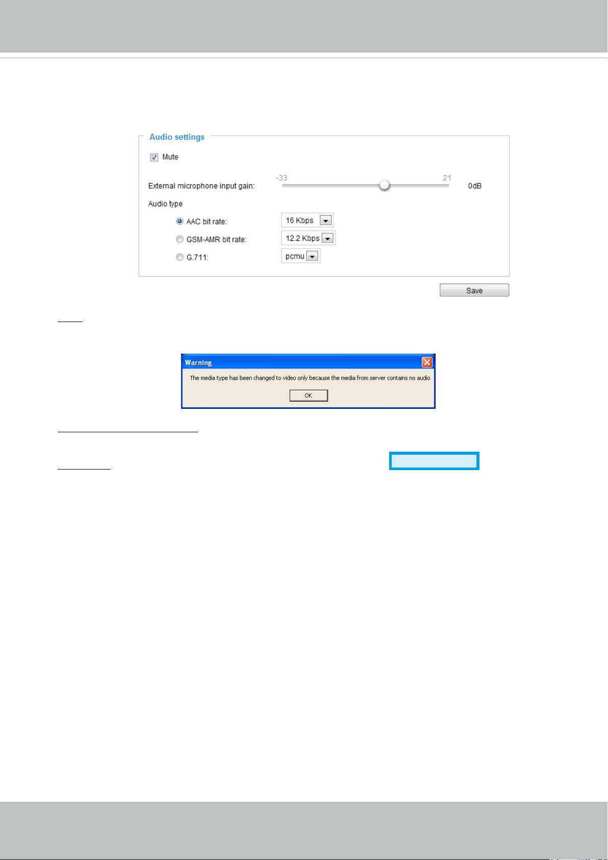
VIVOTEK
Media > Audio
Audio Settings
Mute: Select this option to disable audio transmission from the Network Camera to all clients. Note
that if muted, no audio data will be transmitted even if audio transmission is enabled on the Client
Settings page. In that case, the following message is displayed:
External microphone input: Select the gain of the external audio input according to ambient
conditions. Adjust the gain from +21 db (most sensitive) or -33 db (least sensitive).
Audio type: Select audio codec AAC or GSM-AMR and the bit rate
■ AAC provides good sound quality at the cost of higher bandwidth consumption. The bit rates are
selectable from: 16Kbps, 32Kbps, 48Kbps, 64Kbps, 96Kbps, and 128Kbps.
■ GSM-ARM is designed to optimize speech quality and requires less bandwidth. The bit rates are
selectable from: 4.75Kbps, 5.15Kbps, 5.90Kbps, 6.7Kbps, 7.4Kbps, 7.95Kbps, 10.2Kbps, and
12.2Kbps.
■ G.711 also provides good sound quality and requires about 64Kbps. Select pcmu (μ-Law) or
pcma (A-Law) mode.
When completed with the settings on this page, click Save to enable the settings.
Advanced Mode
.
60 - User's Manual
Page 61
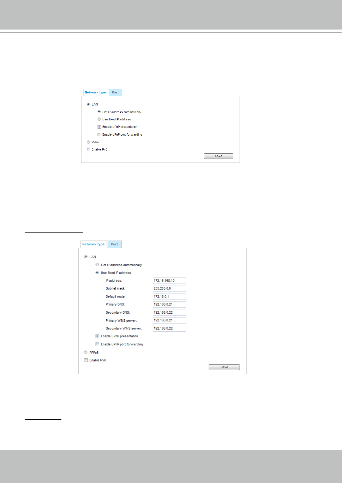
VIVOTEK
Network > General settings
This section explains how to congure a wired network connection for the Network Camera.
Network Type
LAN
Select this option when the Network Camera is deployed on a local area network (LAN) and is intended
to be accessed by local computers. The default setting for the Network Type is LAN. Rememer to click
Save when you complete the Network setting.
Get IP address automatically: Select this option to obtain an available dynamic IP address assigned by
the DHCP server each time the camera is connected to the LAN.
Use xed IP address: Select this option to manually assign a static IP address to the Network Camera.
1. You can make use of VIVOTEK Installation Wizard 2 on the software CD to easily set up the Network
Camera on LAN. Please refer to Software Installation on page 16 for details.
2. Enter the Static IP, Subnet mask, Default router, and Primary DNS provided by your ISP.
Subnet mask: This is used to determine if the destination is in the same subnet. The default value is
“255.255.255.0”.
Default router: This is the gateway used to forward frames to destinations in a different subnet. Invalid
router setting will fail the transmission to destinations in different subnet.
User's Manual - 61
Page 62
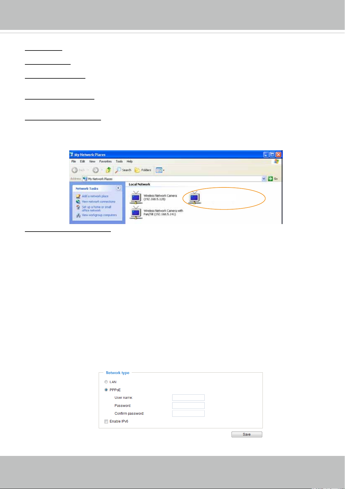
VIVOTEK
Primary DNS: The primary domain name server that translates hostnames into IP addresses.
Secondary DNS: Secondary domain name server that backups the Primary DNS.
Primary WINS server: The primary WINS server that maintains the database of computer names and IP
addresses.
Secondary WINS server: The secondary WINS server that maintains the database of computer names
and IP addresses.
TM
Enable UPnP presentation: Select this option to enable UPnP
presentation for your Network Camera
so that whenever a Network Camera is presented to the LAN, shortcuts of connected Network Cameras
will be listed in My Network Places. You can click the shortcut to link to the web browser. Currently,
TM
UPnP
UPnP
is supported by Windows XP or later. Note that to utilize this feature, please make sure the
TM
component is installed on your computer.
Mega-pixel Network Camera (192.168.5.151)
Enable UPnP port forwarding: To access the Network Camera from the Internet, select this option to
allow the Network Camera to open ports on the router automatically so that video streams can be sent
out from a LAN. To utilize of this feature, make sure that your router supports UPnP
TM
and it is activated.
PPPoE (Point-to-point over Ethernet)
Select this option to congure your Network Camera to make it accessible from anywhere as long as
there is an Internet connection. Note that to utilize this feature, it requires an account provided by your
ISP.
Follow the steps below to acquire your Network Camera’s public IP address.
1. Set up the Network Camera on the LAN.
2. Go to Conguration > Event > Event settings > Add server (please refer to Add server on page 98) to
add a new email or FTP server.
3. Go to Conguration > Event > Event settings > Add media (please refer to Add media on page 103).
Select System log so that you will receive the system log in TXT le format which contains the
Network Camera’s public IP address in your email or on the FTP server.
4. Go to Conguration > Network > General settings > Network type. Select PPPoE and enter the user
name and password provided by your ISP. Click Save to enable the setting.
5. The Network Camera will reboot.
6. Disconnect the power to the Network Camera; remove it from the LAN environment.
62 - User's Manual
Page 63
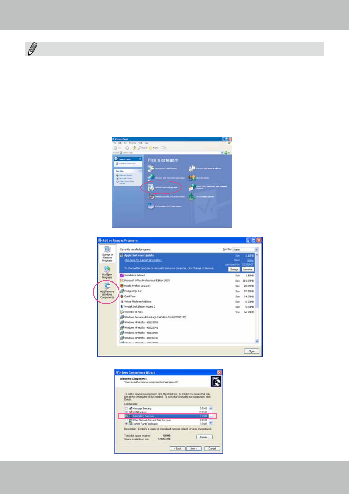
VIVOTEK
NOTE:
NOTE
► If the default ports are already used by other devices connected to the same router, the Network
Camera will select other ports for the Network Camera.
TM
► If UPnP
is not supported by your router, you will see the following message:
Error: Router does not support UPnP port forwarding.
TM
► Steps to enable the UPnP
Note that you must log on to the computer as a system administrator to install the UPnP
user interface on your computer:
TM
components.
1. Go to Start, click Control Panel, then click Add or Remove Programs.
2. In the Add or Remove Programs dialog box, click Add/Remove Windows Components.
3.
In the Windows Components Wizard dialog box, select Networking Services and click Details.
User's Manual - 63
Page 64
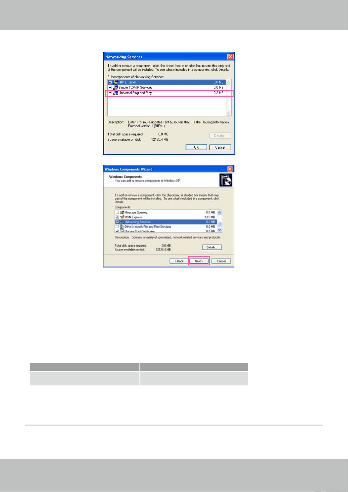
VIVOTEK
4. In the Networking Services dialog box, select Universal Plug and Play and click OK.
5. Click Next in the following window.
TM
6. Click Finish. UPnP
► How does UPnP
UPnP
TM
networking technology provides automatic IP conguration and dynamic discovery of devices
TM
is enabled.
work?
added to a network. Services and capabilities offered by networked devices, such as printing and le
sharing, are available among each other without the need for cumbersome network conguration. In
the case of Network Cameras, you will see Network Camera shortcuts under the My Network Places.
► Enabling UPnP port forwarding allows the Network Camera to open a secondary HTTP port on the
router-not HTTP port-meaning that you have to add the secondary HTTP port number to the Network
Camera’s public address in order to access the Network Camera from the Internet. For example,
when the HTTP port is set to 80 and the secondary HTTP port is set to 8080, refer to the list below for
the Network Camera’s IP address.
From the Internet In LAN
http://203.67.124.123:8080 http://192.168.4.160 or
http://192.168.4.160:8080
► If the PPPoE settings are incorrectly configured or the Internet access is not working, restore the
Network Camera to factory default; please refer to Restore on page 43 for details. After the Network
Camera is reset to factory default, it will be accessible on the LAN.
64 - User's Manual
Page 65
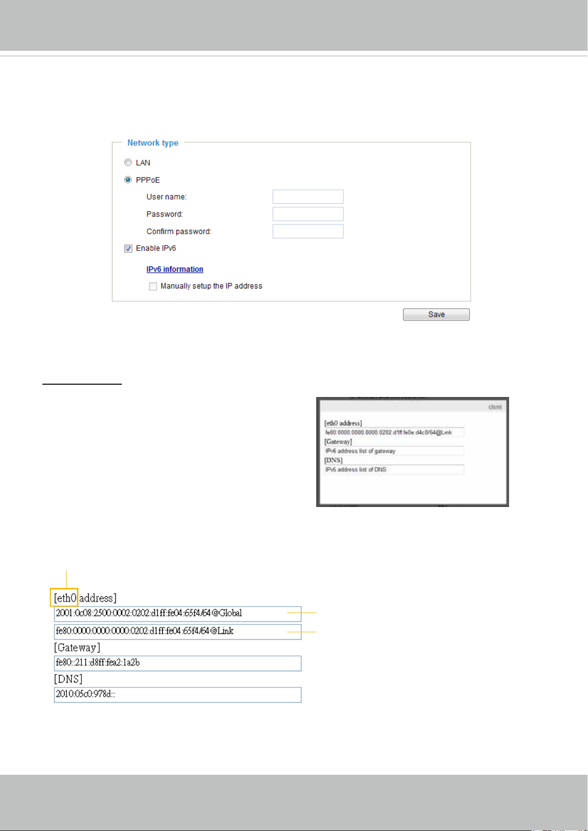
VIVOTEK
Enable IPv6
Select this option and click Save to enable IPv6 settings.
Please note that this only works if your network environment and hardware equipment support IPv6. The
browser should be Microsoft
®
Internet Explorer 6.5, Mozilla Firefox 3.0 or above.
When IPv6 is enabled, by default, the network camera will listen to router advertisements and be
assigned with a link-local IPv6 address accordingly.
IPv6 Information: Click this button to obtain the IPv6 information as shown below. You may need to click
the Save button rst to acquire related information.
If your IPv6 settings are successful, the IPv6 address list will be listed in the pop-up window. The IPv6
address will be displayed as follows:
Refers to Ethernet
Link-global IPv6 address/network mask
Link-local IPv6 address/network mask
User's Manual - 65
Page 66
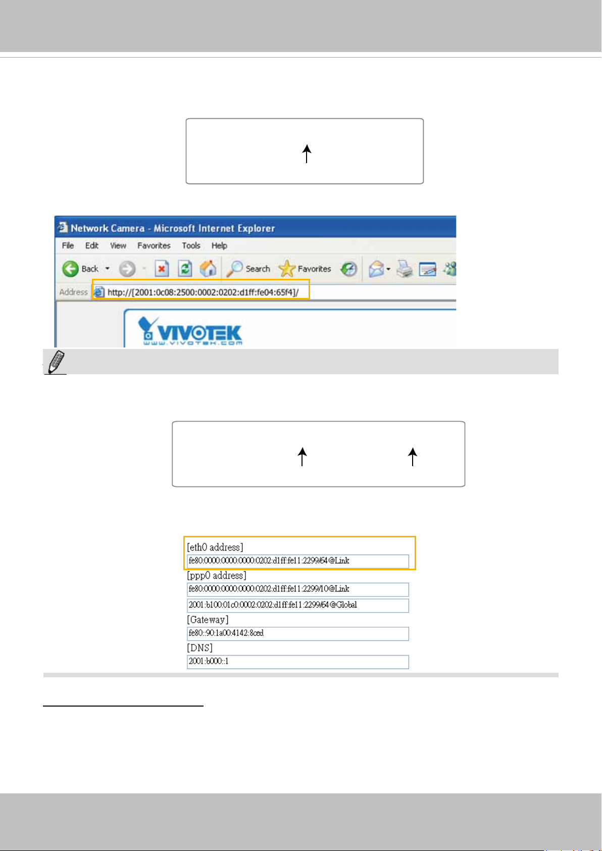
VIVOTEK
Please follow the steps below to link to an IPv6 address:
1. Open your web browser.
2. Enter the link-global or link-local IPv6 address in the address bar of your web browser.
3. The format should be:
http://[2001:0c08:2500:0002:0202:d1ff:fe04:65f4]/
IPv6 address
4. Press Enter on the keyboard or click Refresh button to refresh the webpage.
For example:
NOTE:
NOTE
► If you have a Secondary HTTP port (the default value is 8080), you can also link to the webpage in
the following address format: (Please refer to HTTP streaming on page 69 for detailed information.)
http://[2001:0c08:2500:0002:0202:d1ff:fe04:65f4]/:8080
IPv6 address
Secondary HTTP port
► If you choose PPPoE as the Network Type, the [PPP0 address] will be displayed in the IPv6
information column as shown below.
Manually setup the IP address: Select this option to manually set up IPv6 settings if your network
environment does not have DHCPv6 server and router advertisements-enabled routers.
If you check this item, the following blanks will be displayed for you to enter the corresponding
information:
66 - User's Manual
Page 67
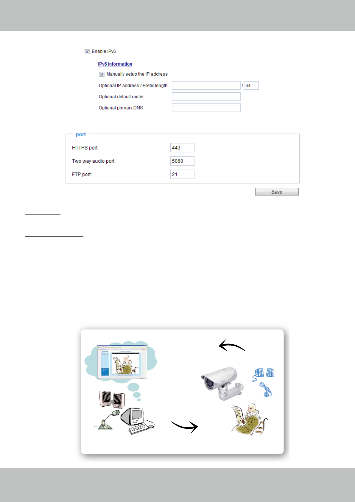
Port
VIVOTEK
HTTPS port: By default, the HTTPS port is set to 443. It can also be assigned to another port number
between 1025 and 65535.
Two way audio port: By default, the two way audio port is set to 5060. Also, it can also be assigned to
another port number between 1025 and 65535.
The Network Camera supports two way audio communication so that operators can transmit and receive
audio simultaneously. By using the Network Camera’s built-in or external microphone and an external
speaker, you can communicate with people around the Network Camera.
Note that as JPEG only transmits a series of JPEG images to the client, to enable the two-way audio
function, make sure the video mode is set to “MPEG-4” on the Media > Video > Stream settings page
and the media option is set to “Media > Video > Stream settings” on the Client Settings page. Please
refer to Client Settings on page 29 and Stream settings on page 88.
Audio transmitted to operators
America
Audio transmitted from operators
Taiwan
User's Manual - 67
Page 68
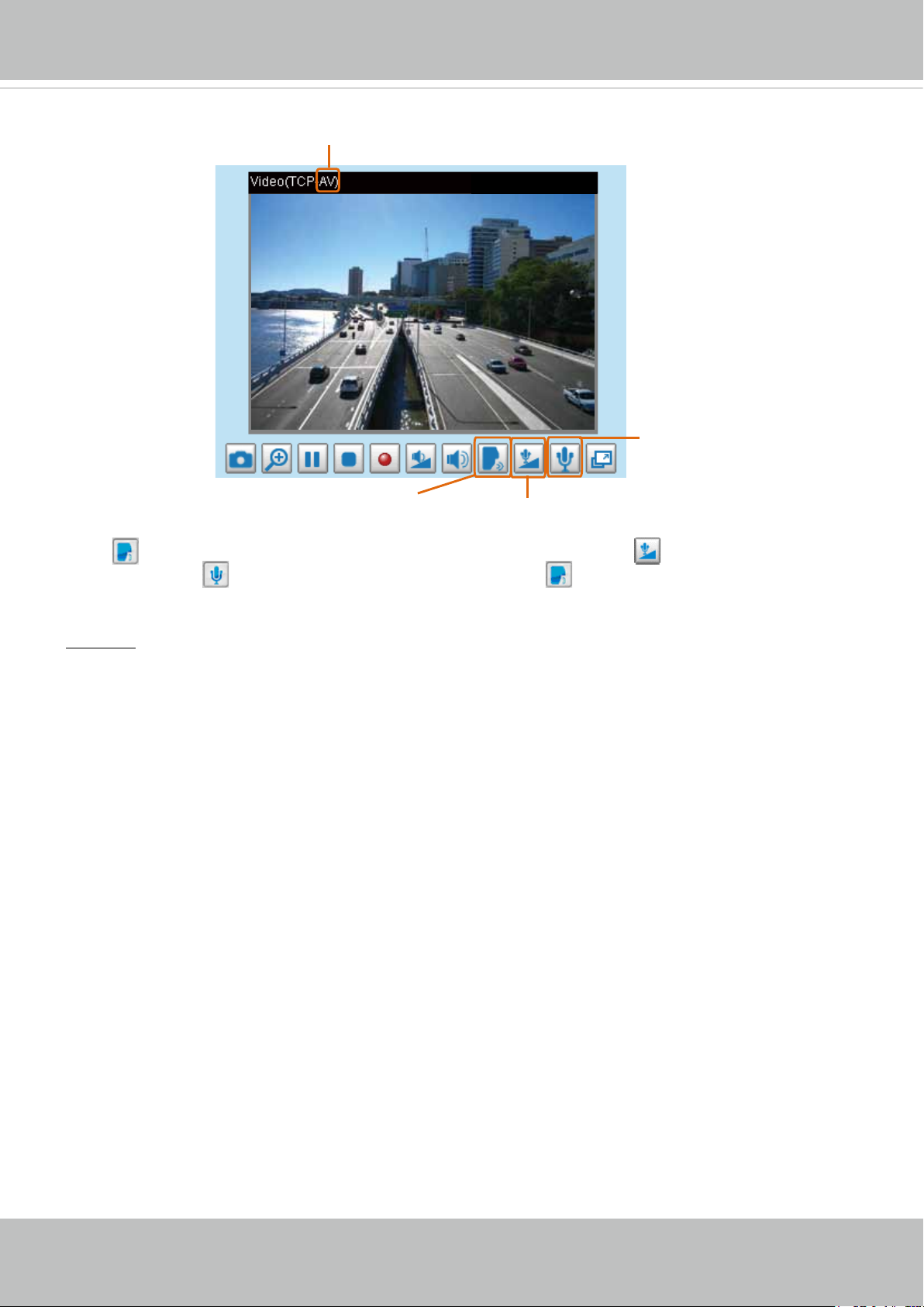
VIVOTEK
Mic Volume
Audio is being transmitted to the Network Camera
2012/08/09 17:08:56
Mute
Talk Button
Click to enable audio transmission to the Network Camera; click to adjust the volume of
microphone; click
to turn off the audio. To stop talking, click again.
FTP port: The FTP server allows the user to save recorded video clips. You can utilize VIVOTEK's
Installation Wizard 2 to upgrade the rmware via FTP server. By default, the FTP port is set to 21. It also
can be assigned to another port number between 1025 and 65535.
68 - User's Manual
Page 69
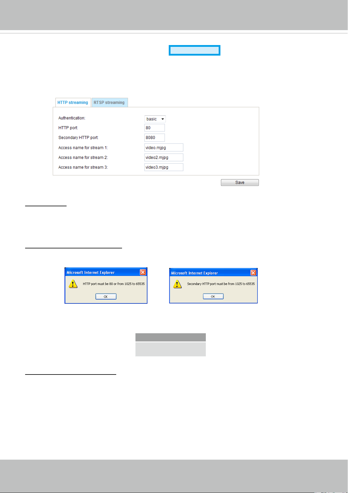
VIVOTEK
Network > Streaming protocols
Advanced Mode
HTTP streaming
To utilize HTTP authentication, make sure that your have set a password for the Network Camera rst;
please refer to Security > User account on page 79 for details.
Authentication: Depending on your network security requirements, the Network Camera provides two
types of security settings for an HTTP transaction: basic and digest.
If basic authentication is selected, the password is sent in plain text format and there can be potential
risks of being intercepted. If digest authentication is selected, user credentials are encrypted using MD5
algorithm and thus provide better protection against unauthorized accesses.
HTTP port / Secondary HTTP port: By default, the HTTP port is set to 80 and the secondary HTTP port is
set to 8080. They can also be assigned to another port number between 1025 and 65535. If the ports are
incorrectly assigned, the following warning messages will be displayed:
To access the Network Camera on the LAN, both the HTTP port and secondary HTTP port can be used
to access the Network Camera. For example, when the HTTP port is set to 80 and the secondary HTTP
port is set to 8080, refer to the list below for the Network Camera’s IP address.
On the LAN
http://192.168.4.160 or
http://192.168.4.160:8080
Access name for stream 1 ~ 3: This Network camera supports multiple streams simultaneously. The
access name is used to differentiate the streaming source. Users can click Media > Video > Stream
settings to set up the video quality of linked streams. For more information about how to set up the video
quality, please refer to Stream settings on page 88.
When using Mozilla Firefox or Netscape to access the Network Camera and the video mode is set to
JPEG, users will receive video comprised of continuous JPEG images. This technology, known as “server
push”, allows the Network Camera to feed live pictures to Mozilla Firefox and Netscape.
User's Manual - 69
Page 70
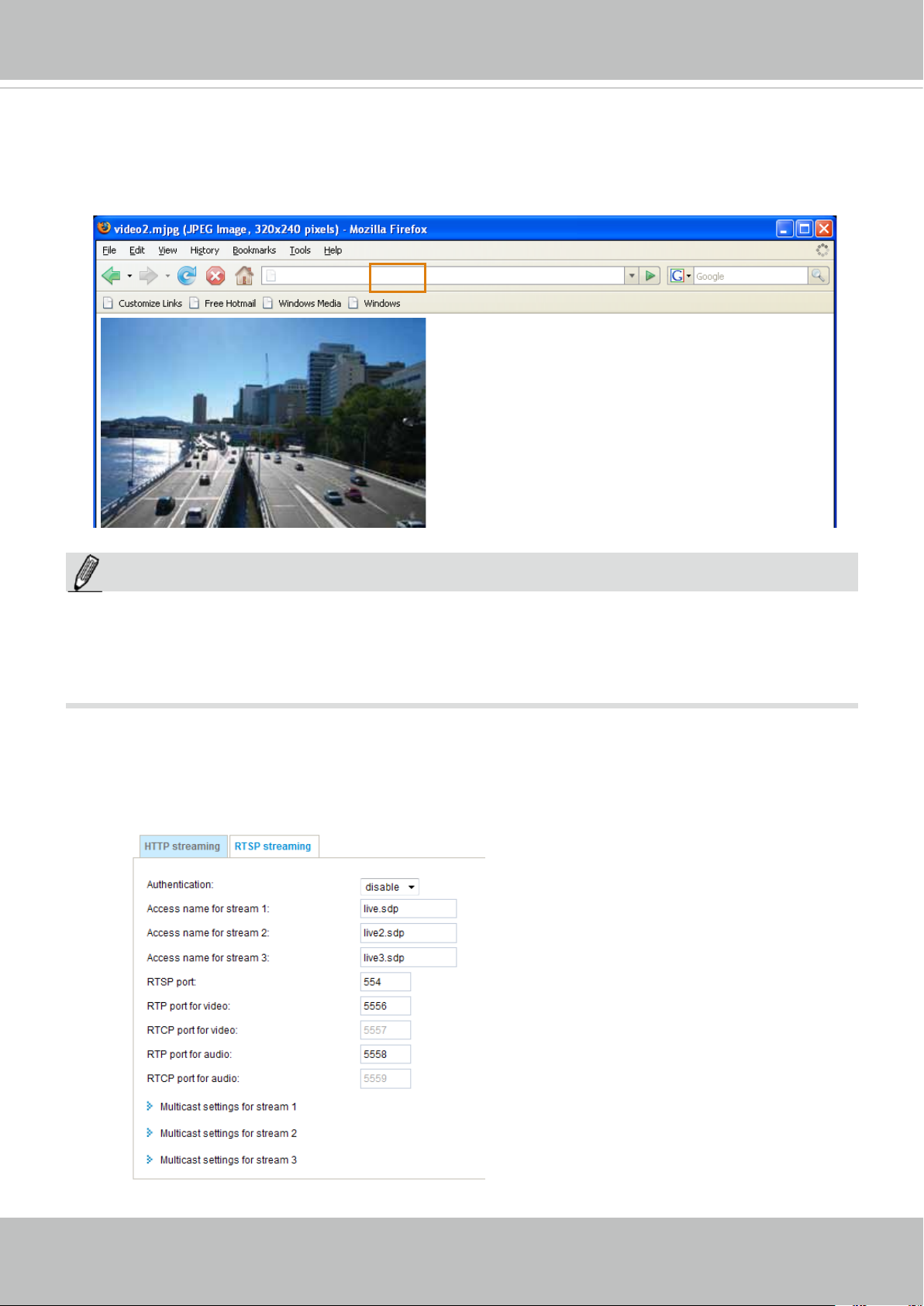
VIVOTEK
URL command -- http://<ip address>:<http port>/<access name for stream 1 ~ 3>
For example, when the Access name for stream 2 is set to video2.mjpg:
1. Launch Mozilla Firefox or Netscape.
2. Type the above URL command in the address bar. Press Enter.
3. The JPEG images will be displayed in your web browser.
http://192.168.5.151/video2.mjpg
NOTE:
NOTE
®
► Microsoft
Internet Explorer does not support server push technology; therefore, using http://<ip
address>:<http port>/<access name for stream 1 ~ 3> will fail to access the Network Camera.
► Users can only use URL commands to request the stream 5. For more information about URL
commands, please refer to page 121.
RTSP Streaming
To utilize RTSP streaming authentication, make sure that you have set a password for the Network
Camera rst; please refer to Security > User account on page 79 for details.
70 - User's Manual
Page 71
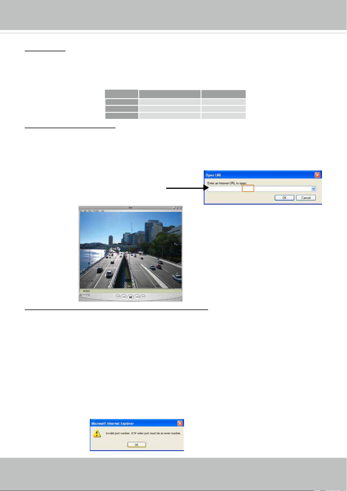
VIVOTEK
Authentication: Depending on your network security requirements, the Network Camera provides three
types of security settings for streaming via RTSP protocol: disable, basic, and digest.
If basic authentication is selected, the password is sent in plain text format, but there can be potential
risks of it being intercepted. If digest authentication is selected, user credentials are encrypted using
MD5 algorithm, thus providing better protection against unauthorized access.
The availability of the RTSP streaming for the three authentication modes is listed in the following table:
Quick Time player Real Player
Disable O O
Basic O O
Digest O X
Access name for stream 1 ~ 3: This Network camera supports multiple streams simultaneously. The
access name is used to differentiate the streaming source.
If you want to use an RTSP player to access the Network Camera, you have to set the video mode to
H.264 / MPEG-4 and use the following RTSP URL command to request transmission of the streaming
data.
rtsp://<ip address>:<rtsp port>/<access name for stream1 ~ 3>
For example, when the access name for stream 1 is set to live.sdp:
1. Launch an RTSP player.
2. Choose File > Open URL. A URL dialog box will pop up.
3. Type the above URL command in the text box.
rtsp://192.168.5.151:554/live.sdp
4. The live video will be displayed in your player as shown
below.
Video 16:38:01 2011/06/25
RTSP port /RTP port for video, audio/ RTCP port for video, audio
■ RTSP (Real-Time Streaming Protocol) controls the delivery of streaming media. By default, the port
number is set to 554.
■ The RTP (Real-time Transport Protocol) is used to deliver video and audio data to the clients. By
default, the RTP port for video is set to 5556 and the RTP port for audio is set to 5558.
■ The RTCP (Real-time Transport Control Protocol) allows the Network Camera to transmit the data by
monitoring the Internet trafc volume. By default, the RTCP port for video is set to 5557 and the RTCP
port for audio is set to 5559.
The ports can be changed to values between 1025 and 65535. The RTP port must be an even number
and the RTCP port is the RTP port number plus one, and thus is always an odd number. When the RTP
port changes, the RTCP port will change accordingly.
If the RTP ports are incorrectly assigned, the following warning message will be displayed:
User's Manual - 71
Page 72
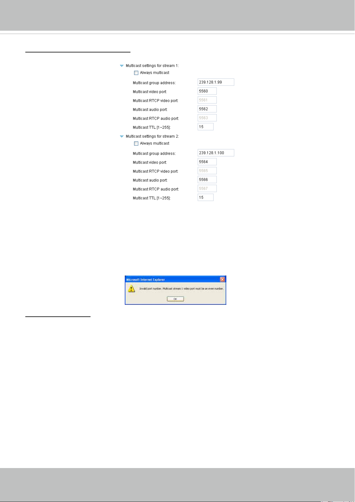
VIVOTEK
Multicast settings for stream 1 ~ 3: Click the items to display the detailed configuration information.
Select the Always multicast option to enable multicast for stream 1 ~ 3.
Unicast video transmission delivers a stream through point-to-point transmission; multicast, on the other
hand, sends a stream to the multicast group address and allows multiple clients to acquire the stream at
the same time by requesting a copy from the multicast group address. Therefore, enabling multicast can
effectively save Internet bandwith.
The ports can be changed to values between 1025 and 65535. The multicast RTP port must be an even
number and the multicast RTCP port number is the multicast RTP port number plus one, and thus is
always odd. When the multicast RTP port changes, the multicast RTCP port will change accordingly.
If the multicast RTP video ports are incorrectly assigned, the following warning message will be
displayed:
Multicast TTL [1~255]: The multicast TTL (Time To Live) is the value that tells the router the range a
packet can be forwarded.
72 - User's Manual
Page 73
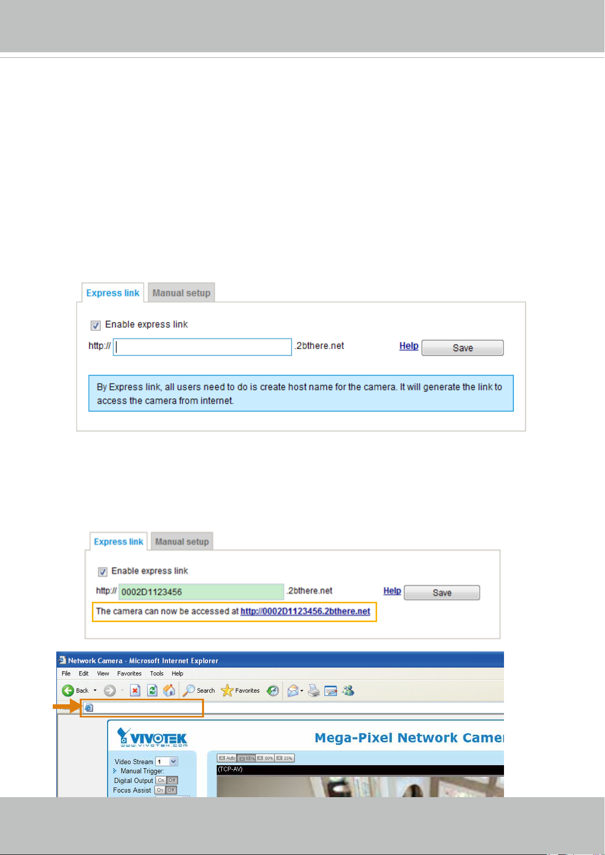
VIVOTEK
2010/12/10 17:08:56
Network > DDNS
This section explains how to congure the dynamic domain name service for the Network
Camera. DDNS is a service that allows your Network Camera, especially when assigned
with a dynamic IP address, to have a xed host and domain name.
Express link
Express Link is a free service provided by VIVOTEK server, which allows users to register
a domain name for a network device. One URL can only be mapped to one MAC address.
This service will check out if the host name is valid and automatically open a port on your
router. Unlike DDNS, the user has to manually check out UPnP port forwarding, Express
Link is more convenient and easy to set up.
Please follow the steps below to enable Express Link:
1. Make sure that your router supports UPnP port forwarding and it is activated.
2. Check Enable express link.
3. Enter a host name for the network device and click Save. If the host name has been used
by another device, a warning message will show up. If the host name is valid, it will show a
message as shown below.
https://0002D1123456.2bthere.net
User's Manual - 73
Page 74
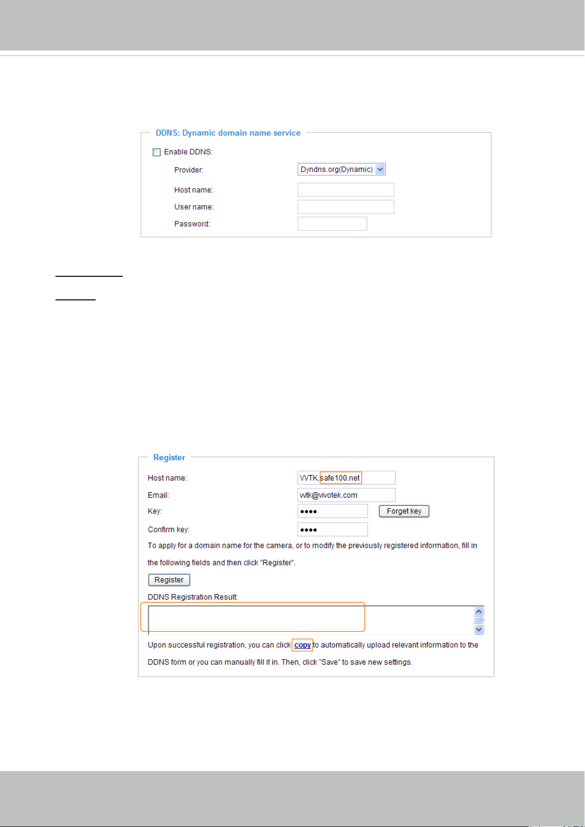
VIVOTEK
Manual setup
DDNS: Dynamic domain name service
Enable DDNS: Select this option to enable the DDNS setting.
Provider: Select a DDNS provider from the provider drop-down list.
VIVOTEK offers Safe100.net, a free dynamic domain name service, to VIVOTEK customers. It
is recommended that you register Safe100.net to access VIVOTEK’s Network Cameras from the
Internet. Additionally, we offer other DDNS providers, such as Dyndns.org(Dynamic), Dyndns.
org(Custom), TZO.com, DHS.org, CustomSafe100, dyn-interfree.it.
Note that before utilizing this function, please apply for a dynamic domain account rst.
■ Safe100.net
1. In the DDNS column, select Safe100.net from the drop-down list. Click I accept after reviewing
the terms of the Service Agreement.
2. In the Register column, ll in the Host name (xxxx.safe100.net), Email, Key, and Conrm Key,
and click Register. After a host name has been successfully created, a success message will
be displayed in the DDNS Registration Result column.
[Register] Successfully Your account information has
been mailed to registered e-mail address
3. Click Copy and all the registered information will automatically be uploaded to the corresponding
elds in the DDNS column at the top of the page as seen in the picture.
74 - User's Manual
Page 75
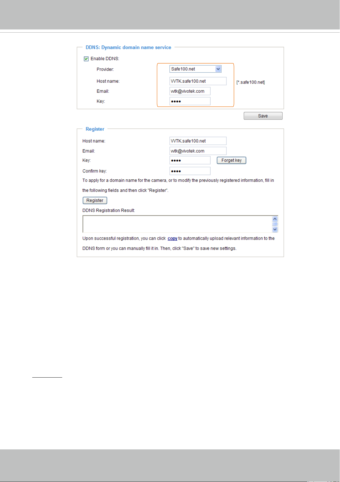
VIVOTEK
[Register] Successfully Your account information has
been mailed to registered e-mail address
4. Select Enable DDNS and click Save to enable the setting.
■ CustomSafe100
VIVOTEK offers documents to establish a CustomSafe100 DDNS server for distributors and
system integrators. You can use CustomSafe100 to register a dynamic domain name if your
distributor or system integrators offer such services.
1. In the DDNS column, select CustomSafe100 from the drop-down list.
2. In the Register column, ll in the Host name, Email, Key, and Conrm Key; then click Register.
After a host name has been successfully created, you will see a success message in the DDNS
Registration Result column.
3. Click Copy and all for the registered information will be uploaded to the corresponding elds in
the DDNS column.
4. Select Enable DDNS and click Save to enable the setting.
Forget key: Click this button if you have forgotten the key to Safe100.net or CustomSafe100. Your
account information will be sent to your email address.
Refer to the following links to apply for a dynamic domain account when selecting other
DDNS providers:
■ Dyndns.org(Dynamic) / Dyndns.org(Custom): visit http://www.dyndns.com/
■ TZO.com: visit http://www.tzo.com/
■ DHS.org: visit http://www.dhs.org/
■ dyn-interfree.it: visit http://dyn-interfree.it/
User's Manual - 75
Page 76
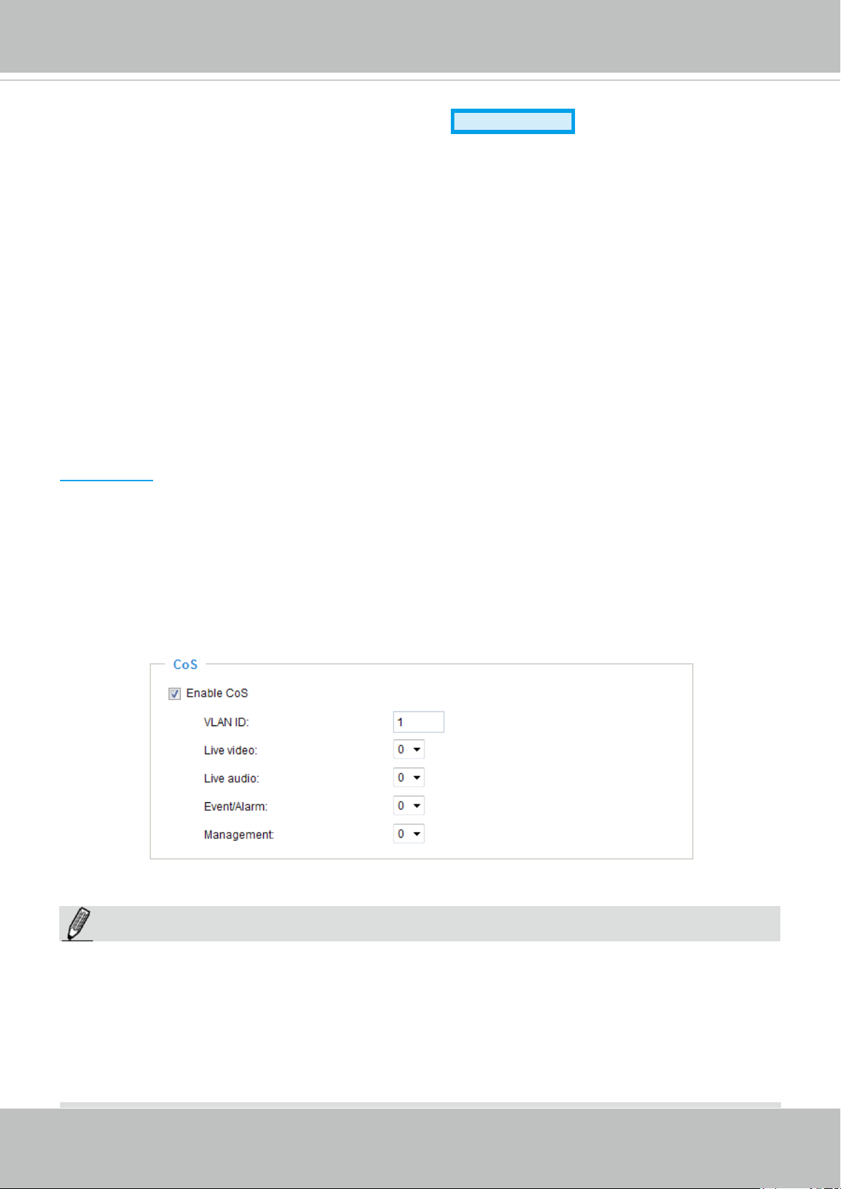
VIVOTEK
Advanced Mode
Network > QoS (Quality of Service)
Quality of Service refers to a resource reservation control mechanism, which guarantees a certain quality
to different services on the network. Quality of service guarantees are important if the network capacity
is insufcient, especially for real-time streaming multimedia applications. Quality can be dened as, for
instance, a maintained level of bit rate, low latency, no packet dropping, etc.
The following are the main benets of a QoS-aware network:
The ability to prioritize trafc and guarantee a certain level of performance to the data ow.
■
The ability to control the amount of bandwidth each application may use, and thus provide higher
■
reliability and stability on the network.
Requirements for QoS
To utilize QoS in a network environment, the following requirements must be met:
All network switches and routers in the network must include support for QoS.
■
The network video devices used in the network must be QoS-enabled.
■
QoS models
CoS (the VLAN 802.1p model)
IEEE802.1p defines a QoS model at OSI Layer 2 (Data Link Layer), which is called CoS, Class of
Service. It adds a 3-bit value to the VLAN MAC header, which indicates the frame priority level from 0
(lowest) to 7 (highest). The priority is set up on the network switches, which then use different queuing
disciplines to forward the packets.
Below is the setting column for CoS. Enter the VLAN ID of your switch (0~4095) and choose the priority
for each application (0~7).
If you assign Video the highest level, the switch will handle video packets rst.
NOTE:
NOTE
► The VLAN Switch (802.1p) is required. The web browsing may fail if the CoS setting is incorrect.
► Class of Service technologies do not guarantee a level of service in terms of bandwidth and delivery
time; they offer a "best-effort." Users can think of CoS as "coarsely-grained" trafc control and QoS as
"nely-grained" trafc control.
► Although CoS is simple to manage, it lacks scalability and does not offer end-to-end guarantees since
it is based on L2 protocol.
76 - User's Manual
Page 77
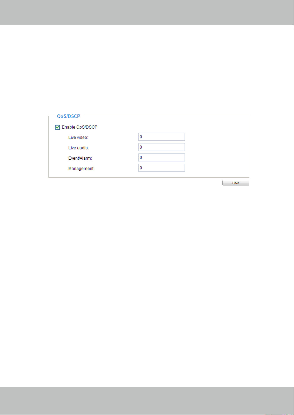
VIVOTEK
QoS/DSCP (the DiffServ model)
DSCP-ECN defines QoS at Layer 3 (Network Layer). The Differentiated Services (DiffServ) model is
based on packet marking and router queuing disciplines. The marking is done by adding a eld to the
IP header, called the DSCP (Differentiated Services Codepoint). This is a 6-bit field that provides 64
different class IDs. It gives an indication of how a given packet is to be forwarded, known as the Per Hop
Behavior (PHB). The PHB describes a particular service level in terms of bandwidth, queueing theory,
and dropping (discarding the packet) decisions. Routers at each network node classify packets according
to their DSCP value and give them a particular forwarding treatment; for example, how much bandwidth
to reserve for it.
Below are the setting options of DSCP (DiffServ Codepoint). Specify the DSCP value for each application
(0~63).
User's Manual - 77
Page 78
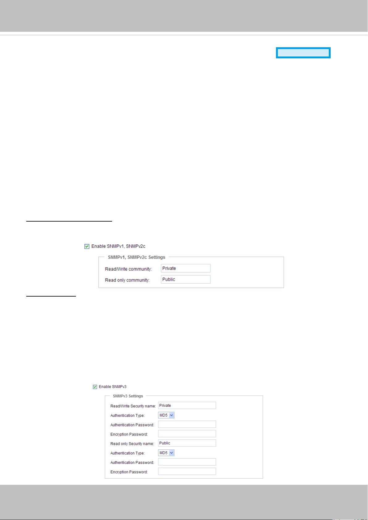
VIVOTEK
Network > SNMP
(Simple Network Management Protocol)
Advanced Mode
This section explains how to use the SNMP on the network camera. The Simple Network
Management Protocol is an application layer protocol that facilitates the exchange of
management information between network devices. It helps network administrators to remotely
manage network devices and nd, solve network problems with ease.
■ The SNMP consists of the following three key components:
1. Manager: Network-management station (NMS), a server which executes applications that monitor and
control managed devices.
2. Agent: A network-management software module on a managed device which transfers the status of
managed devices to the NMS.
3. Managed device: A network node on a managed network. For example: routers, switches, bridges,
hubs, computer hosts, printers, IP telephones, network cameras, web server, and database.
Before conguring SNMP settings on the this page, please enable your NMS rst.
SNMP Conguration
Enable SNMPv1, SNMPv2c
Select this option and enter the names of Read/Write community and Read Only community according to
your NMS settings.
Enable SNMPv3
This option contains cryptographic security, a higher security level, which allows you to set the
Authentication password and the Encryption password.
■ Security name: According to your NMS settings, choose Read/Write or Read Only and enter the
community name.
■ Authentication type: Select MD5 or SHA as the authentication method.
■ Authentication password: Enter the password for authentication (at least 8 characters).
■ Encryption password: Enter a password for encryption (at least 8 characters).
78 - User's Manual
Page 79
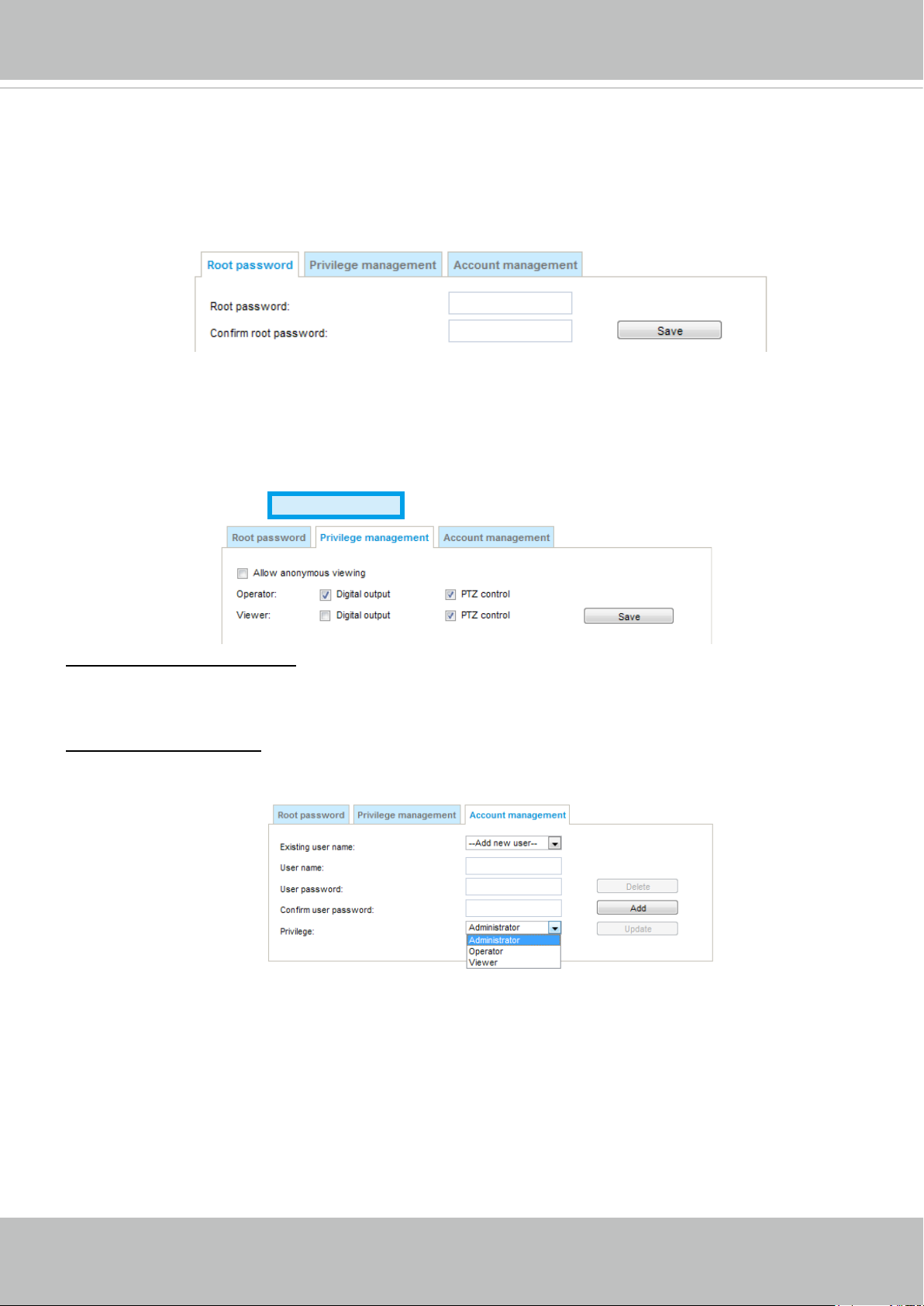
VIVOTEK
Security > User Account
This section explains how to enable password protection and create multiple accounts.
Root Password
The administrator account name is “root”, which is permanent and can not be deleted. If you want to add
more accounts in the Manage User column, please apply the password for the “root” account rst.
1. Type the password identically in both text boxes, then click Save to enable password protection.
2. A window will be prompted for authentication; type the correct user’s name and password in their
respective elds to access the Network Camera.
Privilege Management
Digital Output & PTZ control: You can modify the management privileges of operators or viewers.
Select or deselect the item, then click Save to enable the settings. If you give Viewers the privilege,
Operators will also have the ability to control the Network Camera through the main page. (Please refer
to Conguration on page 34).
Allow anonymous viewing: If you check this item, any client can access the live stream without entering a
User ID and Password.
Advanced Mode
Account Management
Administrators can add up to 20 user accounts.
1. Input the new user’s name and password.
2. Select the privilege level for the new user account. Click Add to enable the setting.
Access rights are sorted by user privilege (Administrator, Operator, and Viewer). Only administrators can
access the Conguration page. Though operators cannot access the Conguration page, they can use
the URL Commands to get and set the value of parameters. For more information, please refer to URL
Commands of the Network Camera on page 121. Viewers access only the main page for live viewing.
Here you also can change a user’s access rights or delete user accounts.
1. Select an existing account to modify.
2. Make necessary changes and click Update or Delete to enable the setting.
User's Manual - 79
Page 80
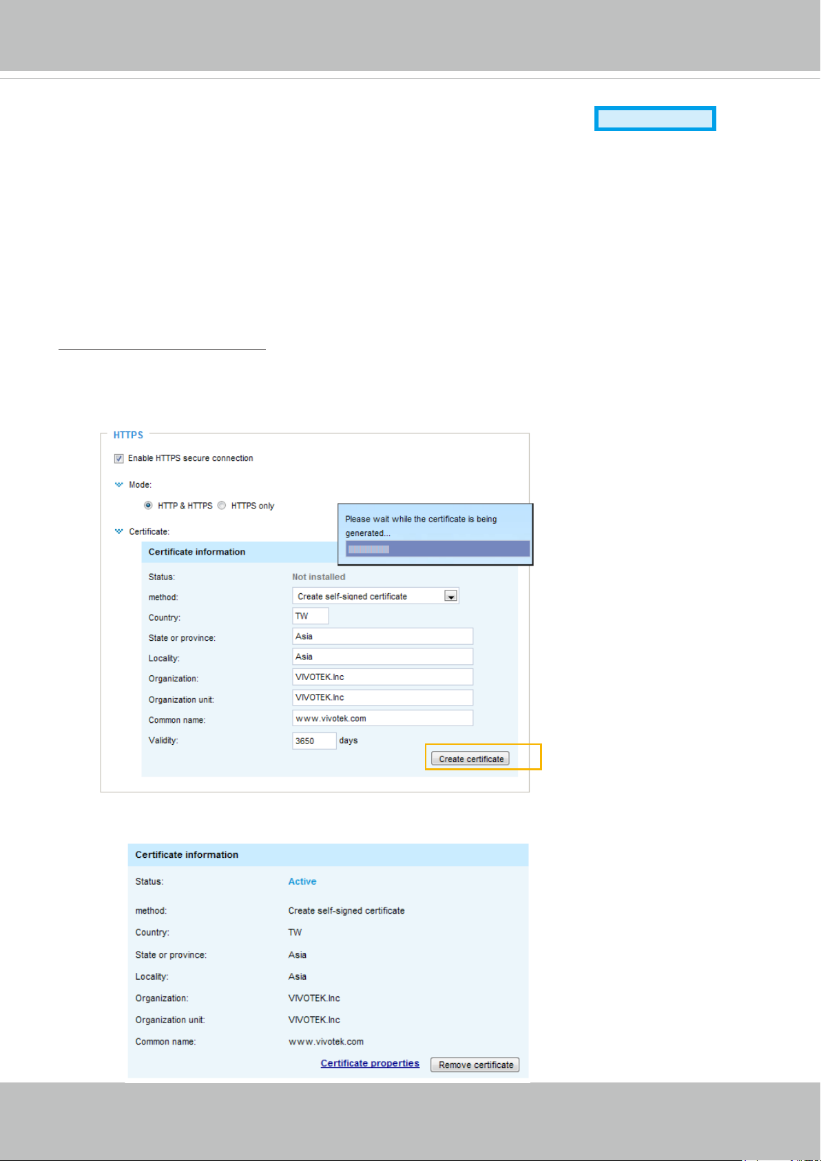
VIVOTEK
Security > HTTPS
(Hypertext Transfer Protocol over SSL)
Advanced Mode
This section explains how to enable authentication and encrypted communication over SSL
(Secure Socket Layer). It helps protect streaming data transmission over the Internet on higher
security level.
Create and Install Certicate Method
Before using HTTPS for communication with the Network Camera, a Certicate must be created rst.
There are three ways to create and install a certicate:
Create self-signed certificate
1. Select this option from a pull-down menu.
2. In the rst column, select Enable HTTPS secure connection, then select a connection option: “HTTP
& HTTPS” or “HTTPS only”.
3. Click Create certicate to generate a certicate.
4. The Certicate Information will automatically be displayed as shown below. You can click Certicate
properties to view detailed information about the certicate.
80 - User's Manual
Page 81
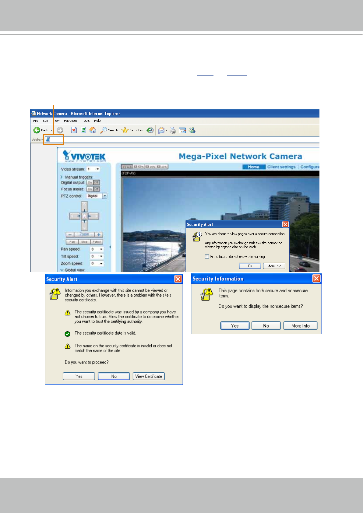
VIVOTEK
https://
5. Click Save to preserve your conguration, and your current session with the camera will change to the
encrypted connection.
6. If your web session does not automatically change to an encrypted HTTPS session, click Home to re-
turn to the main page. Change the URL address from “http://” to “https://“ in the address bar and press
Enter on your keyboard. Some Security Alert dialogs will pop up. Click OK or Yes to enable HTTPS.
https://192.168.5.151/index.html
User's Manual - 81
Page 82
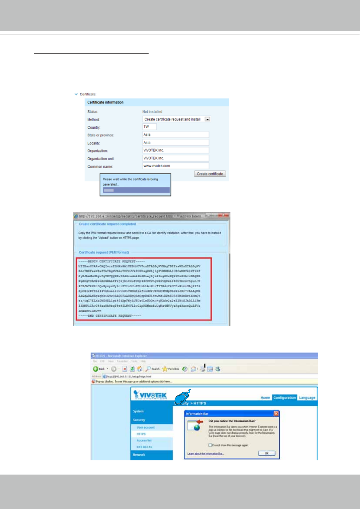
VIVOTEK
Create certificate request and install
1. Select the option from the Method pull-down menu.
2. Click Create certicate to proceed.
3. The following information will show up in a pop-up window after clicking Create. Then click Save
to generate the certicate request.
4. The Certicate request window will prompt.
If you see the following Information bar, click OK and click on the Information bar at the top of
the page to allow pop-ups.
82 - User's Manual
Page 83
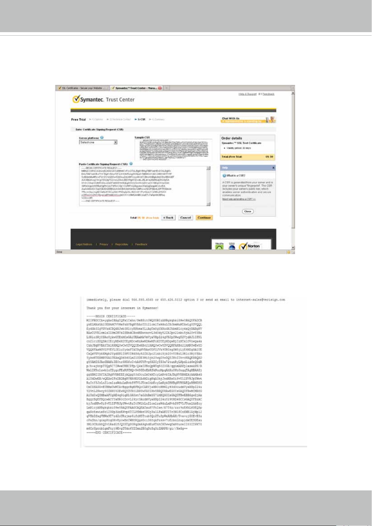
VIVOTEK
5. Look for a trusted certicate authority, such as Symantec’s VeriSign Authentication Services, that
issues digital certicates. Sign in and purchase the SSL certication service. Copy the certicate
request from your request prompt and paste it in the CA’s signing request window. Proceed with
the rest of the process as CA’s instructions on their webpage.
6. Once completed, your SSL certicate should be delivered to you via an email or other means.
Copy the contents of the certicate in the email and paste it in a text/HTML/hex editor/converter,
such as IDM Computer Solutions’ UltraEdit.
User's Manual - 83
Page 84
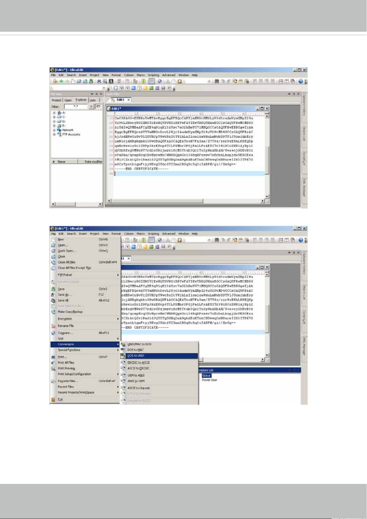
VIVOTEK
7. Open a new edit, paste the certicate contents, and press ENTER at the end of the contents to add an
empty line.
8. Convert le format from DOS to UNIX. Open File menu > Conversions > DOS to Unix.
84 - User's Manual
Page 85
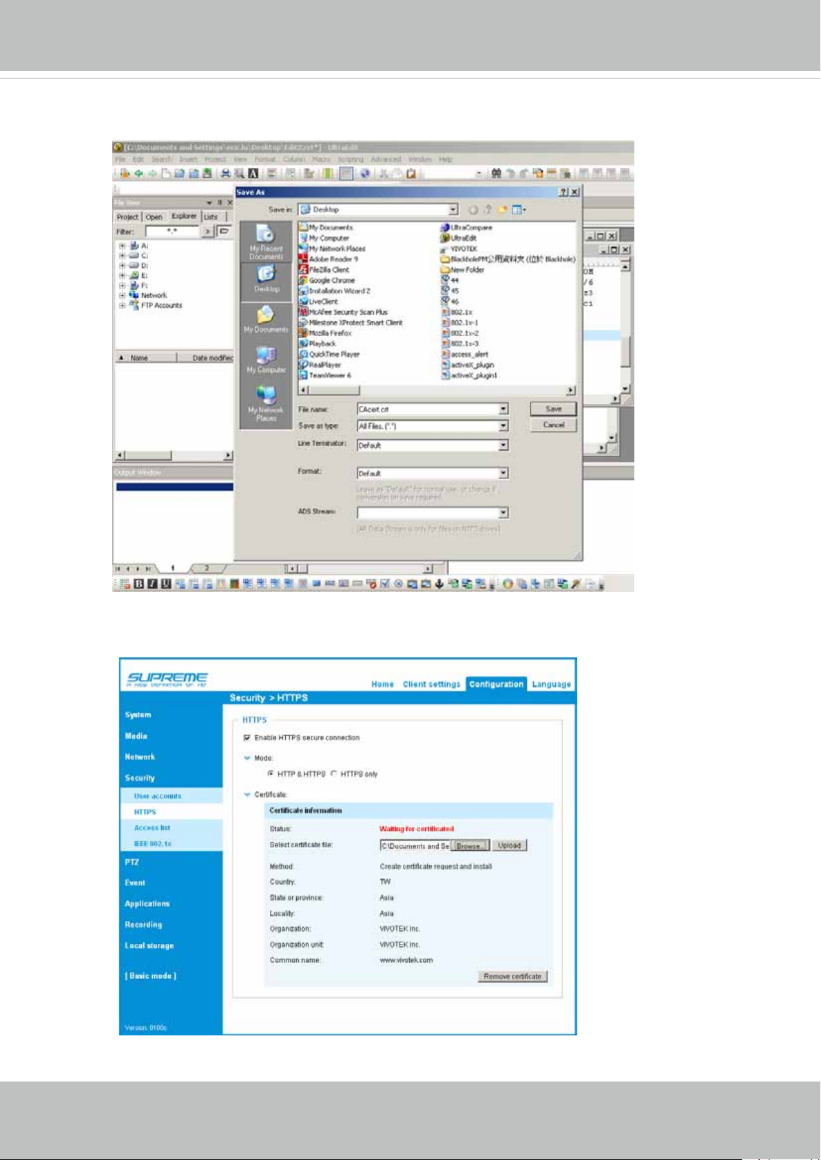
9. Save the edit using the “.crt” extension, using a le name like “CAcert.crt.”
VIVOTEK
10. Return to the original rmware session, use the Browse button to locate the crt certicate le, and
click Upload to enable the certication.
User's Manual - 85
Page 86
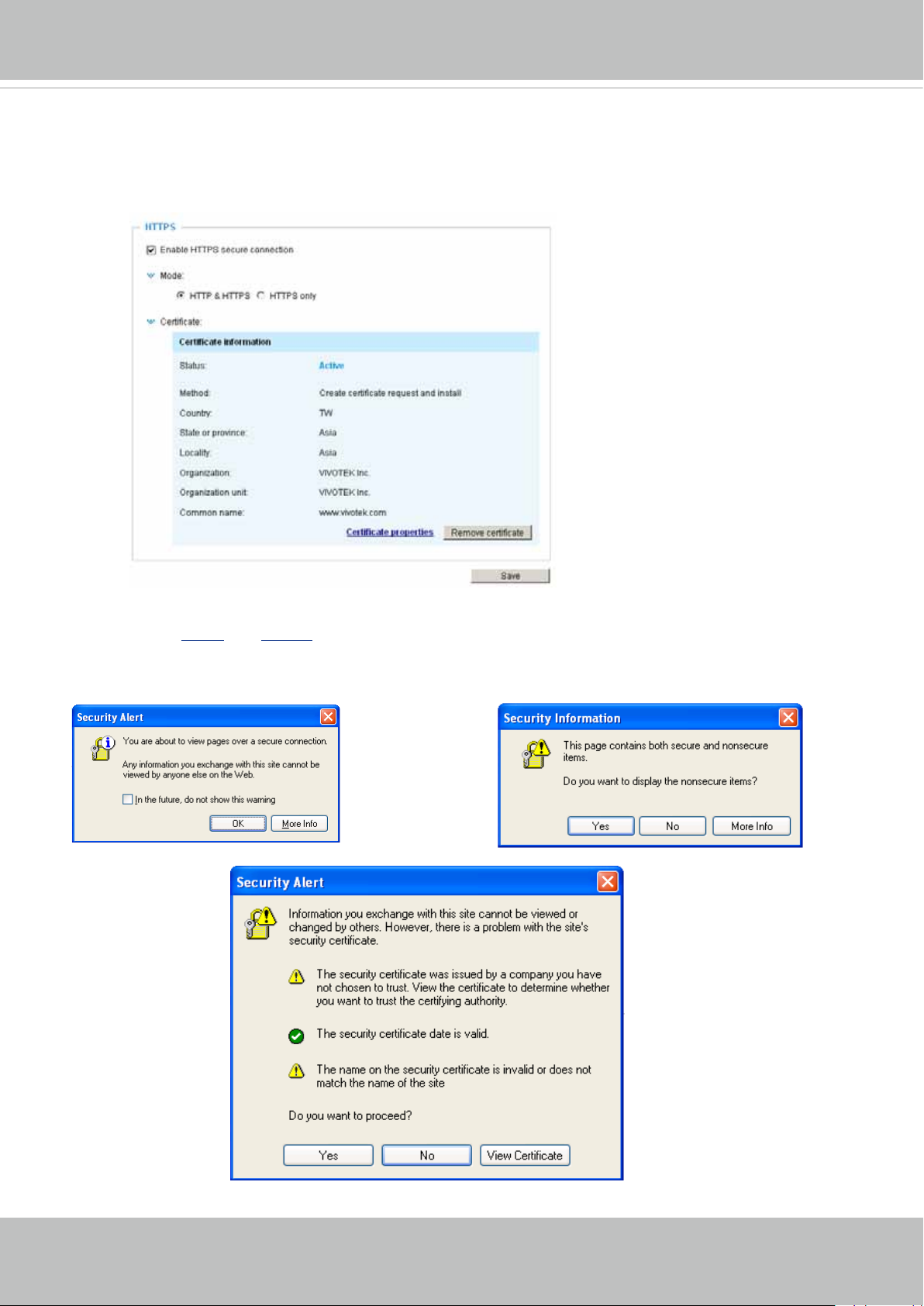
VIVOTEK
11. When the certifice file is successfully loaded, its status will be stated as Active.
Note that a
certicate must have been created and installed before you can click on the “Save" button for
the conguration to take effect.
12.To begin an encrypted HTTPS session, click Home to return to the main page. Change the URL ad-
dress from “http://” to “https://“ in the address bar and press Enter on your keyboard. Some Security
Alert dialogs will pop up. Click OK or Yes to enable HTTPS.
86 - User's Manual
Page 87
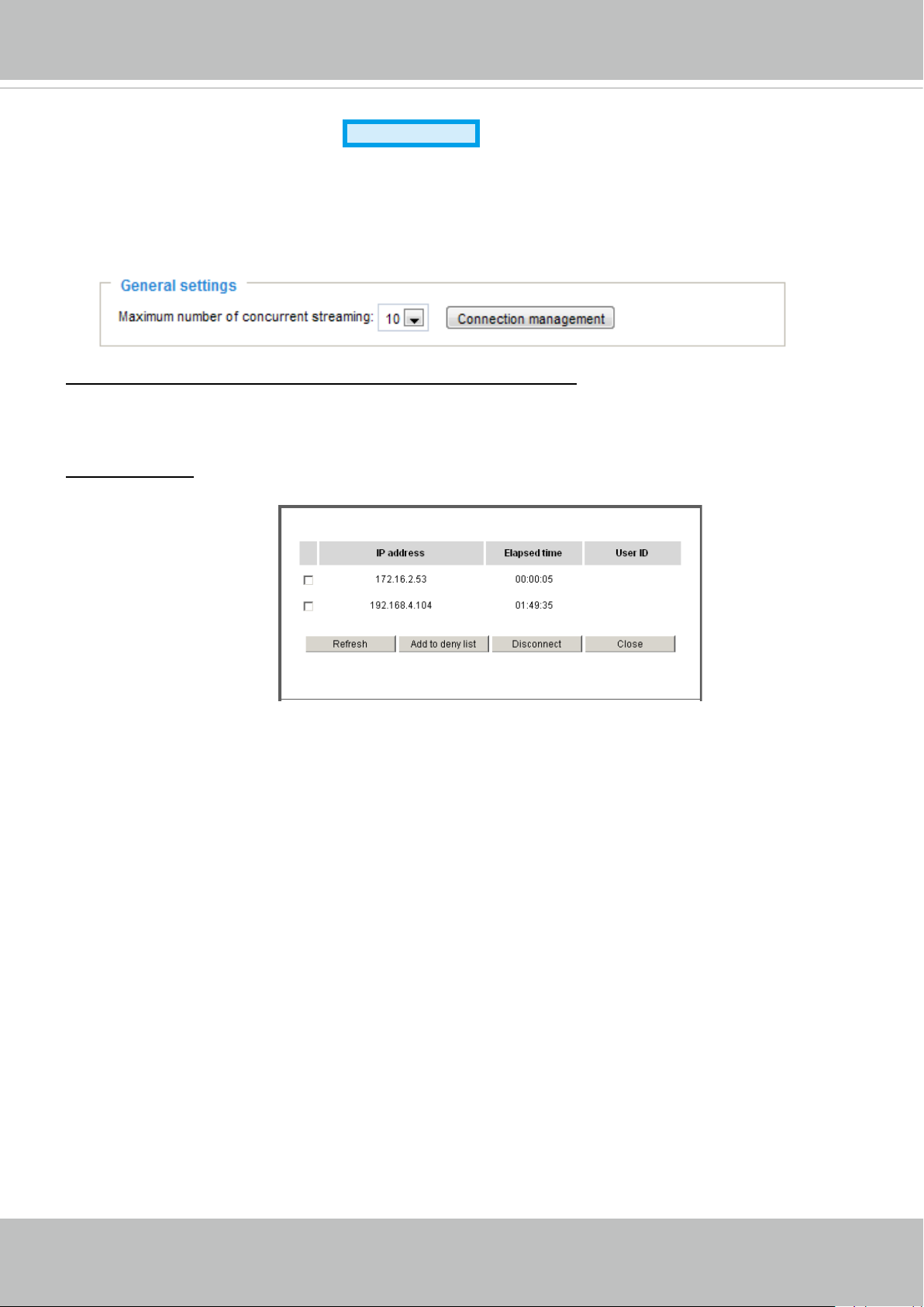
VIVOTEK
Security > Access List
Advanced Mode
This section explains how to control access permission by verifying the client PC’s IP address.
General Settings
Maximum number of concurrent streaming connection(s) limited to: Simultaneous live viewing for 1~10
clients (including stream 1 and stream 2). The default value is 10. If you modify the value and click Save,
all current connections will be disconnected and automatically attempt to re-link (IE Explore or Quick
Time Player).
View Information: Click this button to display the connection status window showing a list of the current
connections. For example:
Note that only consoles that are currently displaying live streaming will be listed in the View Information
list.
■ IP address: Current connections to the Network Camera.
■ Elapsed time: How much time the client has been at the webpage.
■ User ID: If the administrator has set a password for the webpage, the clients have to enter a user name
and password to access the live video. The user name will be displayed in the User ID column. If the
administrator allows clients to link to the webpage without a user name and password, the User ID
column will be empty.
There are some situations which allow clients access to the live video without a user name and
password:
1. The administrator does not set up a root password. For more information about how to set up a root
password and manage user accounts, please refer to Security > User account on page 79.
2. The administrator has set up a root password, but set RTSP Authentication to “disable“. For more
information about RTSP Authentication, please refer to RTSP Streaming on page 70.
3. The administrator has set up a root password, but allows anonymous viewing. For more information
about Allow Anonymous Viewing, please refer to page 79.
User's Manual - 87
Page 88
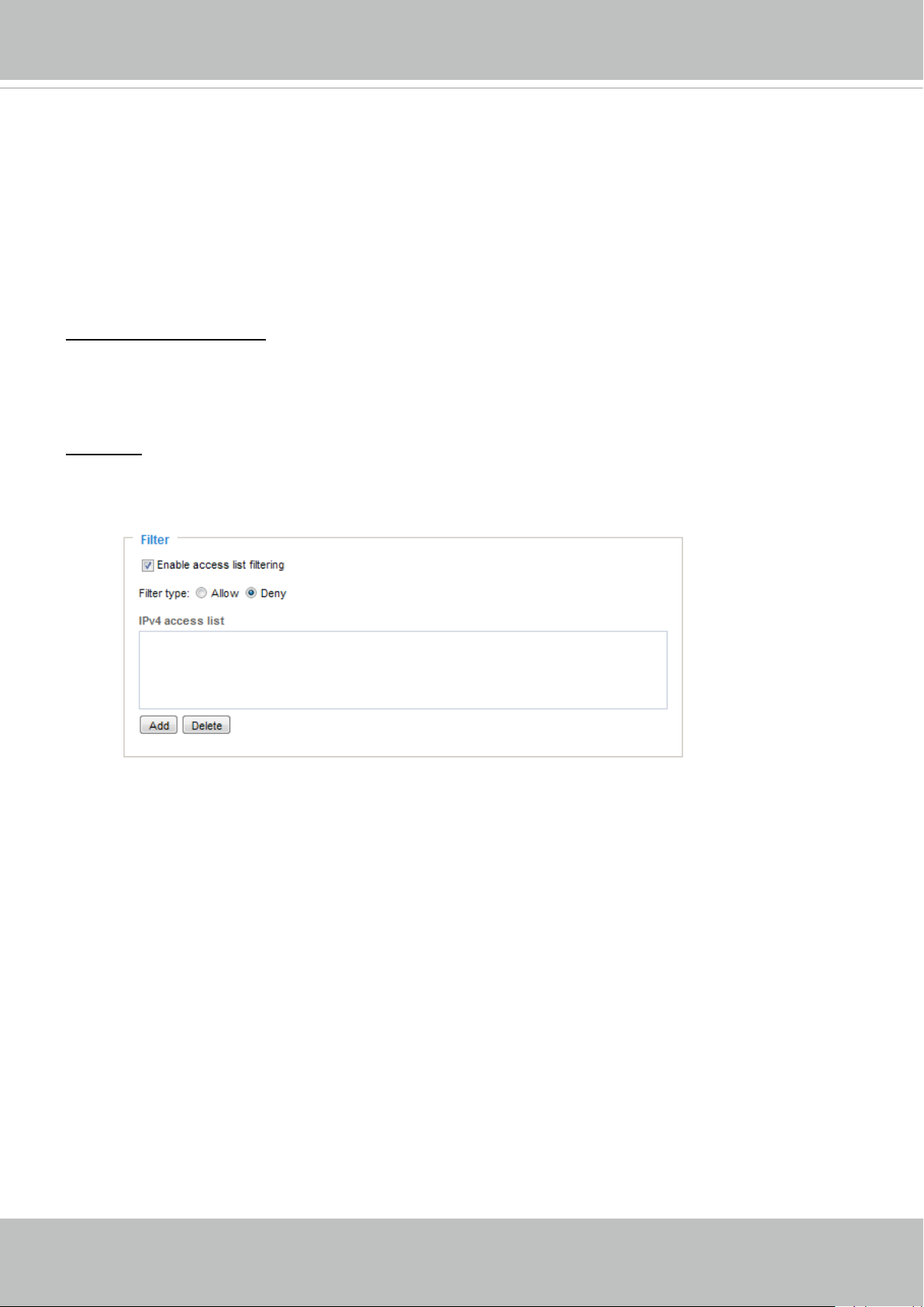
VIVOTEK
■ Refresh: Click this button to refresh all current connections.
■ Add to deny list: You can select entries from the Connection Status list and add them to the Deny List
to deny access. Please note that those checked connections will only be disconnected temporarily
and will automatically try to re-link again (IE Explorer or Quick Time Player). If you want to enable the
denied list, please check Enable access list ltering and click Save in the rst column.
■ Disconnect: If you want to break off the current connections, please select them and click this
button. Please note that those checked connections will only be disconnected temporarily and will
automatically try to re-link again (IE Explore or Quick Time Player).
Enable access list ltering: Check this item and click Save if you want to enable the access list ltering
function.
Filter
Filter type: Select Allow or Deny as the lter type. If you choose Allow Type, only those clients whose
IP addresses are on the Access List below can access the Network Camera, and the others cannot
access. On the contrary, if you choose Deny Type, those clients whose IP addresses are on the Access
List below will not be allowed to access the Network Camera, and the others can access.
Then you can Add a rule to the following Access List. Please note that the IPv6 access list column
will not be displayed unless you enable IPv6 on the Network page. For more information about IPv6
Settings, please refer to Network > General settings on page 61 for detailed information.
88 - User's Manual
Page 89
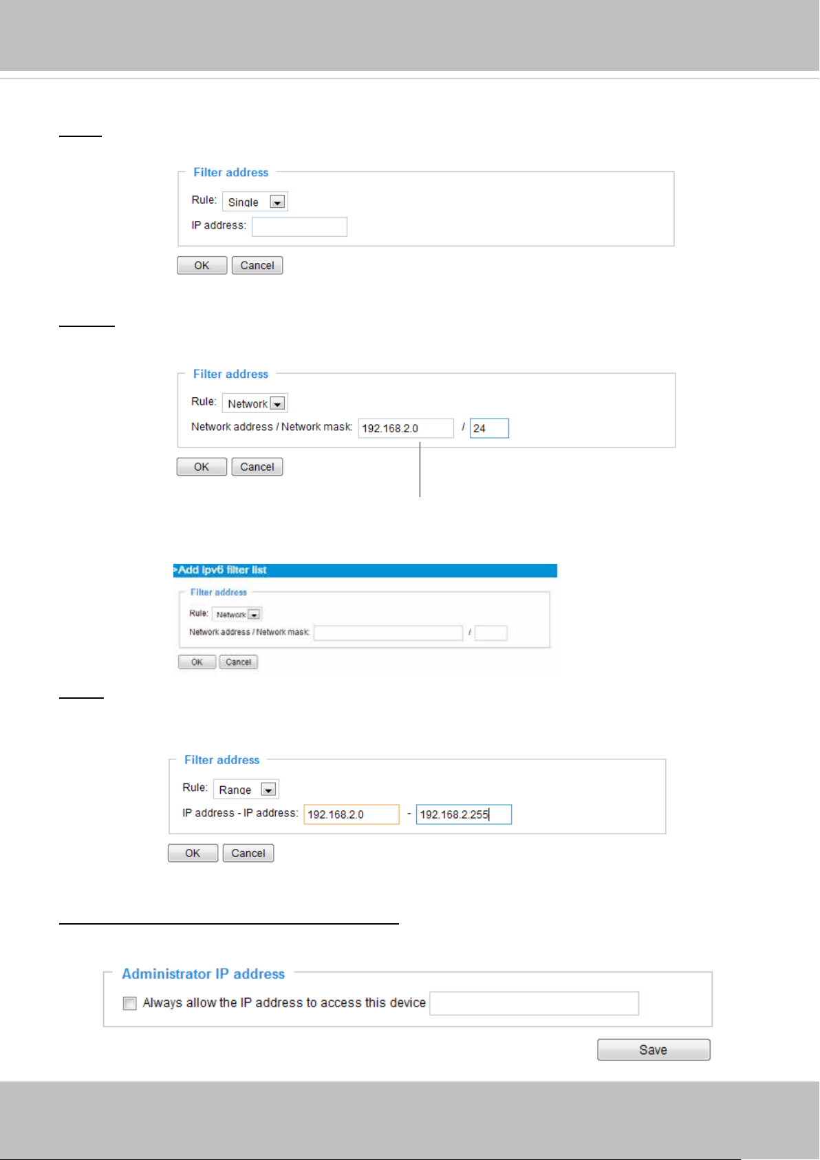
VIVOTEK
There are three types of rules:
Single: This rule allows the user to add an IP address to the Allowed/Denied list.
For example:
192.168.2.1
Network: This rule allows the user to assign a network address and corresponding subnet mask to the
Allow/Deny List. The address and network mask are written in CIDR format.
For example:
IP address 192.168.2.x will be bolcked.
If IPv6 lter is preferred, you will be prompted by the following window. Enter the IPv6 address and the
two-digit prex length to specify the range of IP addresses in your conguration.
Range: This rule allows the user to assign a range of IP addresses to the Allow/Deny List.
Note: This rule is only applied to IPv4.
For example:
Administrator IP address
Always allow the IP address to access this device: You can check this item and add the Administrator’s
IP address in this eld to make sure the Administrator can always connect to the device.
User's Manual - 89
Page 90
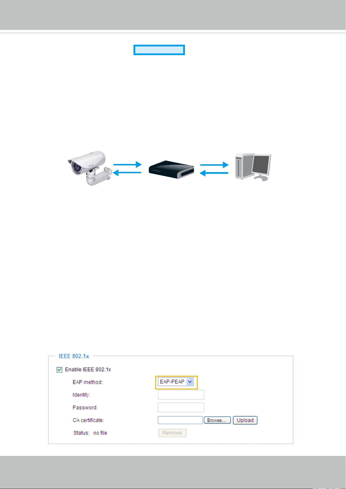
VIVOTEK
Advanced Mode
Security > IEEE 802.1X
Enable this function if your network environment uses IEEE 802.1x, which is a port-based network
access control. The network devices, intermediary switch/access point/hub, and RADIUS server must
support and enable 802.1x settings.
The 802.1x standard is designed to enhance the security of local area networks, which provides
authentication to network devices (clients) attached to a network port (wired or wireless). If all certicates
between client and server are veried, a point-to-point connection will be enabled; if authentication fails,
access on that port will be prohibited. 802.1x utilizes an existing protocol, the Extensible Authentication
Protocol (EAP), to facilitate communication.
The components of a protected network with 802.1x authentication:
■
Supplicant
(Network Camera)
Supplicant: A client end user (camera), which requests authentication.
1.
Authenticator (an access point or a switch): A “go between” which restricts unauthorized end users
2.
Authenticator
(Network Switch)
Authentication Server
(RADIUS Server)
from communicating with the authentication server.
Authentication server (usually a RADIUS server): Checks the client certicate and decides whether to
3.
accept the end user’s access request.
VIVOTEK Network Cameras support two types of EAP methods to perform authentication: EAP-PEAP
■
and EAP-TLS.
Please follow the steps below to enable 802.1x settings:
1. Before connecting the Network Camera to the protected network with 802.1x, please apply a digital
certicate from a Certicate Authority (ie. MIS of your company) which can be validated by a RADIUS
server.
2. Connect the Network Camera to a PC or notebook outside of the protected LAN. Open the
conguration page of the Network Camera as shown below. Select EAP-PEAP or EAP-TLS as the
EAP method. In the following blanks, enter your ID and password issued by the CA, then upload
related certicate(s).
90 - User's Manual
Page 91
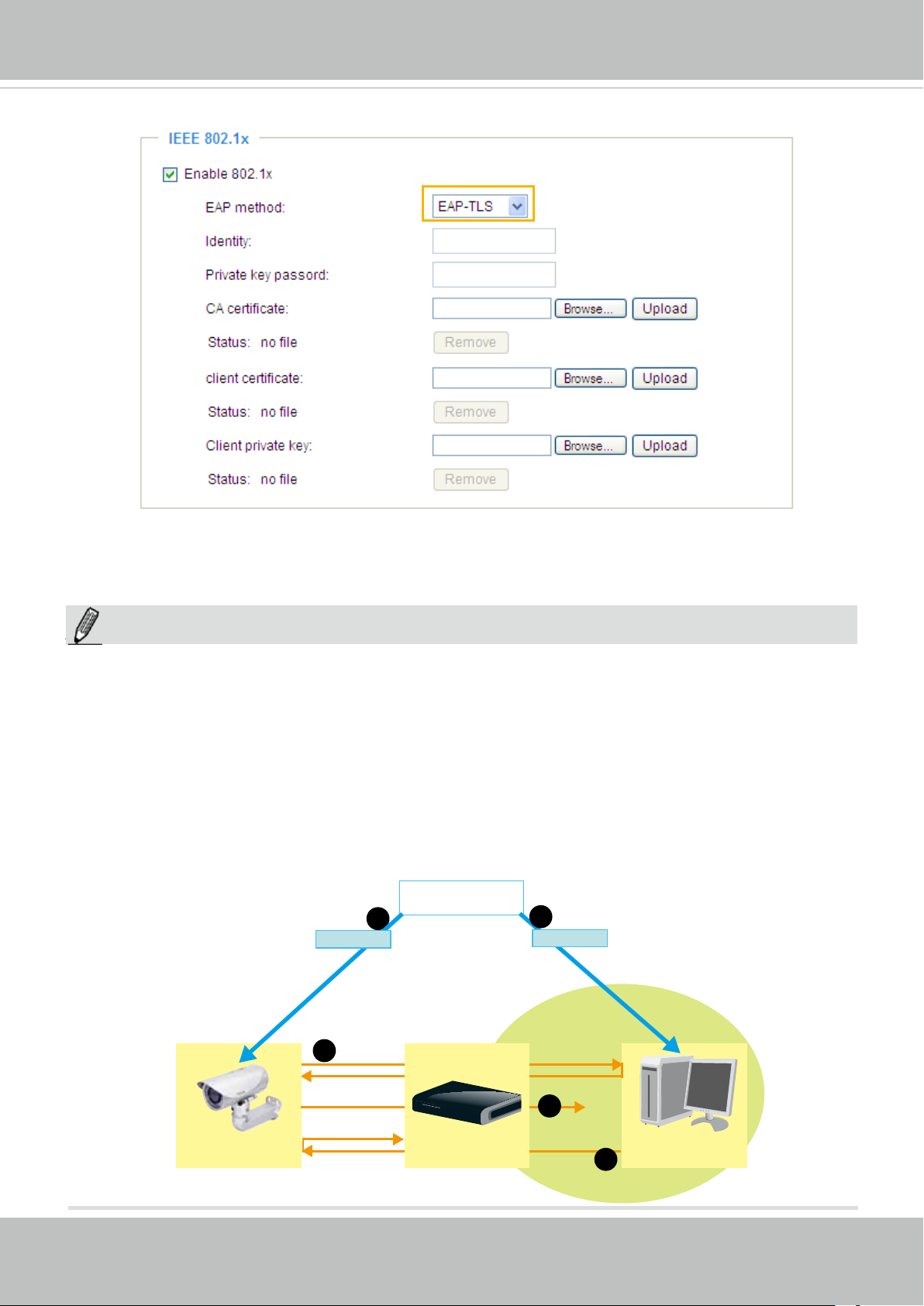
VIVOTEK
3. When all settings are complete, move the Network Camera to the protected LAN by connecting it to an
802.1x enabled switch. The devices will then start the authentication automatically.
NOTE:
NOTE
► The authentication process for 802.1x:
1. The Certicate Authority (CA) provides the required signed certicates to the Network Camera (the
supplicant) and the RADIUS Server (the authentication server).
2. A Network Camera requests access to the protected LAN using 802.1X via a switch (the authenticator).
The client offers its identity and client certicate, which is then forwarded by the switch to the RADIUS
Server, which uses an algorithm to authenticate the Network Camera and returns an acceptance or
rejection back to the switch.
3. The switch also forwards the RADIUS Server’s certicate to the Network Camera.
4. Assuming all certificates are validated, the switch then changes the Network Camera’s state to
authorized and is allowed access to the protected network via a pre-congured port.
Certificate Authority
1
(CA)
Certificate
1
Certificate
VIVOTEK
Network Camera
2
4
Network Switch
Protected LAN
RADIUS Server
3
User's Manual - 91
Page 92
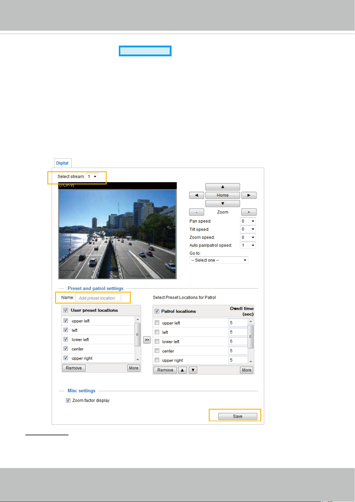
VIVOTEK
PTZ > PTZ settings
Advanced Mode
This section explains how to control the Network Camera’s Pan/Tilt/Zoom operation.
There are two ways to enable the function:
Digital: Control the e-PTZ operation. It allows users to quickly move the focus to a target
area for close-up viewing without physically moving the camera.
Digital PTZ Operation (E-PTZ Operation)
If you select “Digital“, the e-PTZ control settings section will be displayed as shown below:
2012/08/10 17:08:56
Select Stream: Select one of the stream 1~3 to configure the e-PTZ control. Please note that each
stream can possess its own preset and patrol settings. For detailed information about how to set up
preset and patrol settings, please refer to page 94.
92 - User's Manual
Page 93
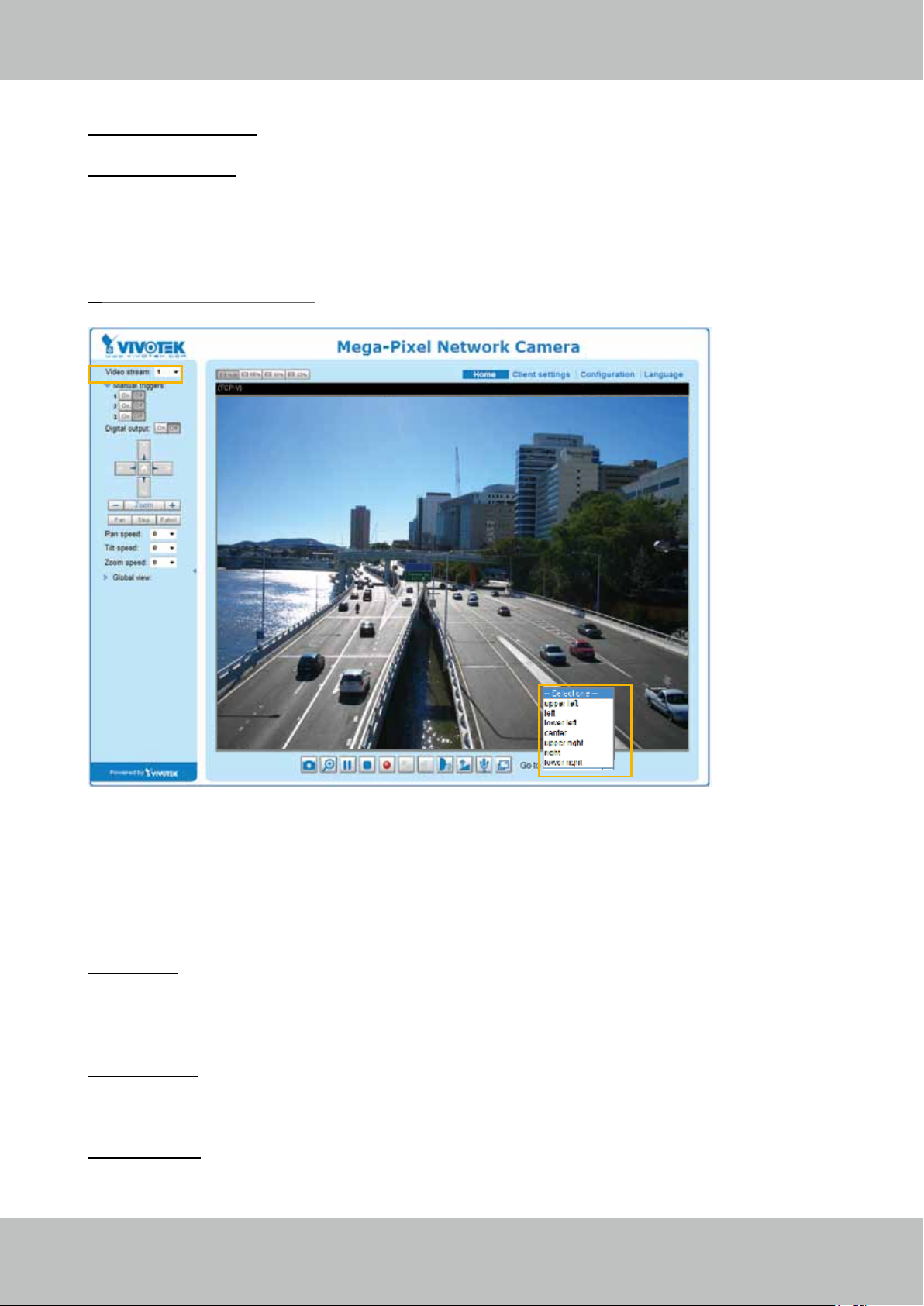
VIVOTEK
Auto pan/patrol speed: Select the speed from 1~5 (slow/fast) to set up the Auto pan/patrol speed
control.
Zoom factor display
If you check this item, the zoom indicator will be displayed on the home page when you zoom in or
zoom out the live viewing window as the picture shown on the next page.
When completed with the settings of e-PTZ, click Save to enable the settings on this page.
Home page in E-PTZ Mode
2012/08/10 17:08:56
x1.0
■ The e-Preset Positions will also be displayed on the home page. Select one from the drop-down
list, and the Network Camera will move to the selected e-preset position.
■ If you have set up different e-preset positions for stream 1~3, you can select one of the video
streams to display its separate e-preset positions.
Global View
In addition to using the e-PTZ control panel, you can also use the mouse to drag or resize the
oating frame to pan/tilt/zoom on the viewing region. The live view window will also move to the
viewing region accordingly.
Move Instantly
If you select this item, the live view window will respond instantly to the operation on the Global
View.
Click on Image
The e-PTZ function also supports “Click on Image“. When you click on any point of the Global View
Window or Live View Window, the viewing region will also move to that point.
User's Manual - 93
Page 94
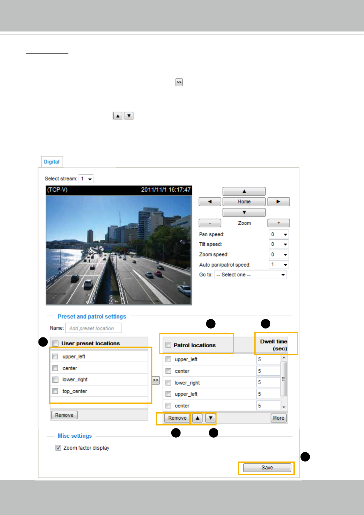
VIVOTEK
Patrol settings
You can select some preset positions for the Network Camera to patrol.
Please follow the steps below to set up a patrol schedule:
1. Select the preset locations on the list, and click
2. The selected preset locations will be displayed on the Patrol locations list.
3. Set the Dwelling time for the preset location during auto patrol.
4. If you want to delete a preset location from the Patrol locations list, select it and click Remove.
5. Select a location and click
6. Select patrol locations you want to save in the list and click Save to enable the patrol settings.
7. To implement the patrol schedule, please go to homepage and click on Patrol button.
to rearrange the patrol order.
2011/03/13 17:08:56
2011/03/10 17:08:56
.
1
x2.1
2
3
94 - User's Manual
54
6
Page 95
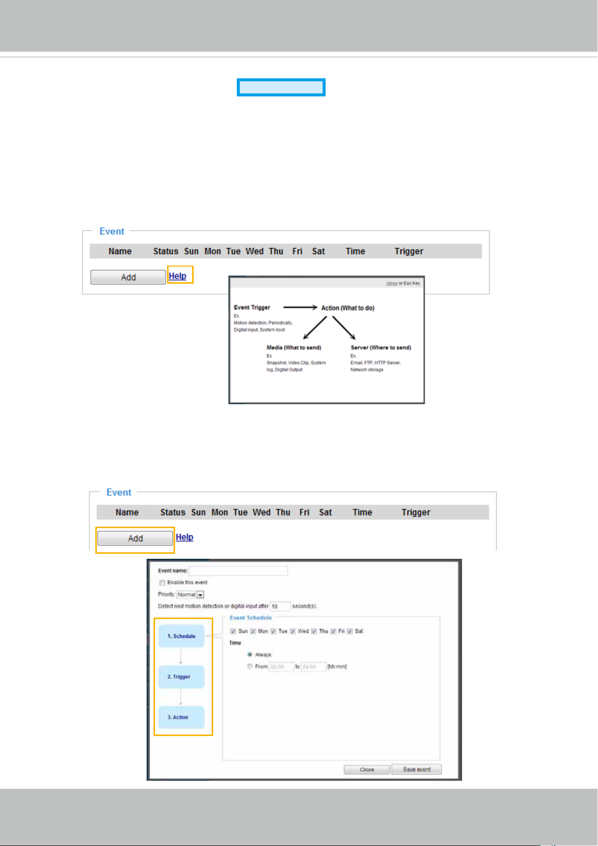
VIVOTEK
Event > Event settings
Advanced Mode
This section explains how to congure the Network Camera to responds to particular situations
(event). A typical application is that when a motion is detected, the Network Camera sends
buffered images to an FTP server or e-mail address as notifications. Click on Help, there is
an illustration shown in the pop-up window explains that an event can be triggered by many
sources, such as motion detection or external digital input devices. When an event is triggered,
you can specify what type of action that will be performed. You can configure the Network
Camera to send snapshots or videos to your email address or FTP site.
Event
To set an event with recorded video or snapshots, it is necessary to configure the server and media
settings so that the Network Camera will know what action to take (such as which server to send the
media les to) when a trigger is activated. An event is an action initiated by a user-dened trigger source
In the Event column, click Add to open the event settings window. Here you can arrange three elements
-- Schedule, Trigger, and Action to set an event. A total of 3 event settings can be congured.
.
User's Manual - 95
Page 96
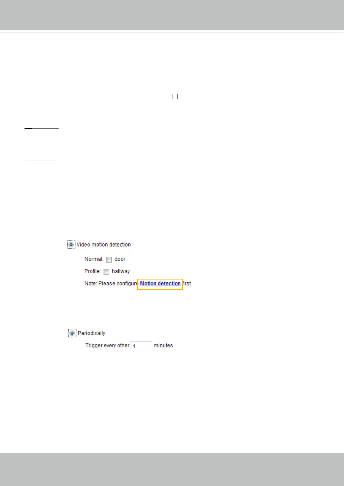
VIVOTEK
■ Event name: Enter a name for the event setting.
■ Enable this event: Select this option to enable the event setting.
■ Priority: Select the relative importance of this event (High, Normal, or Low). Events with a higher
priority setting will be executed rst.
■ Detect next motion detection or digital input after
seconds: Enter the duration in seconds to pause
motion detection after a motion is detected. This can prevent event triggers to be too frequently
delivered.
Schedule
1.
Specify the period of them during which the event trigger will take place. Please select the days of the
week and the time in a day (in 24-hr time format) for the event triggering schedule.
2. Trigger
This is the cause or stimulus which denes when to trigger the Network Camera. The trigger source can
be congured to use the Network Camera’s built-in motion detection mechanism or external digital input
devices.
There are several choices of trigger sources as shown on next page.
detailed conguration options.
■ Video motion detection
This option makes use of the built-in motion detection mechanism as a trigger source. To enable this
function, you need to congure a Motion Detection Window rst. For more information, please refer to
Motion Detection on page 108 for details.
Select the item to display the
■ Periodically
This option allows the Network Camera to trigger periodically for every other dened minute. Up to 999
minutes are allowed.
■ Digital input
This option allows the Network Camera to use an external digital input device or sensor as a trigger
source. Depending on your application, there are many choices of digital input devices on the market
that helps to detect changes in temperature, vibration, sound, and light, etc. Refer to page 111 for DI
and DO settings.
■ System boot
This option triggers the Network Camera when the power to the Network Camera is disconnected.
■ Recording notify
This option allows the Network Camera to trigger when the recording disk is full or when recording
starts to rewrite older data.
96 - User's Manual
Page 97
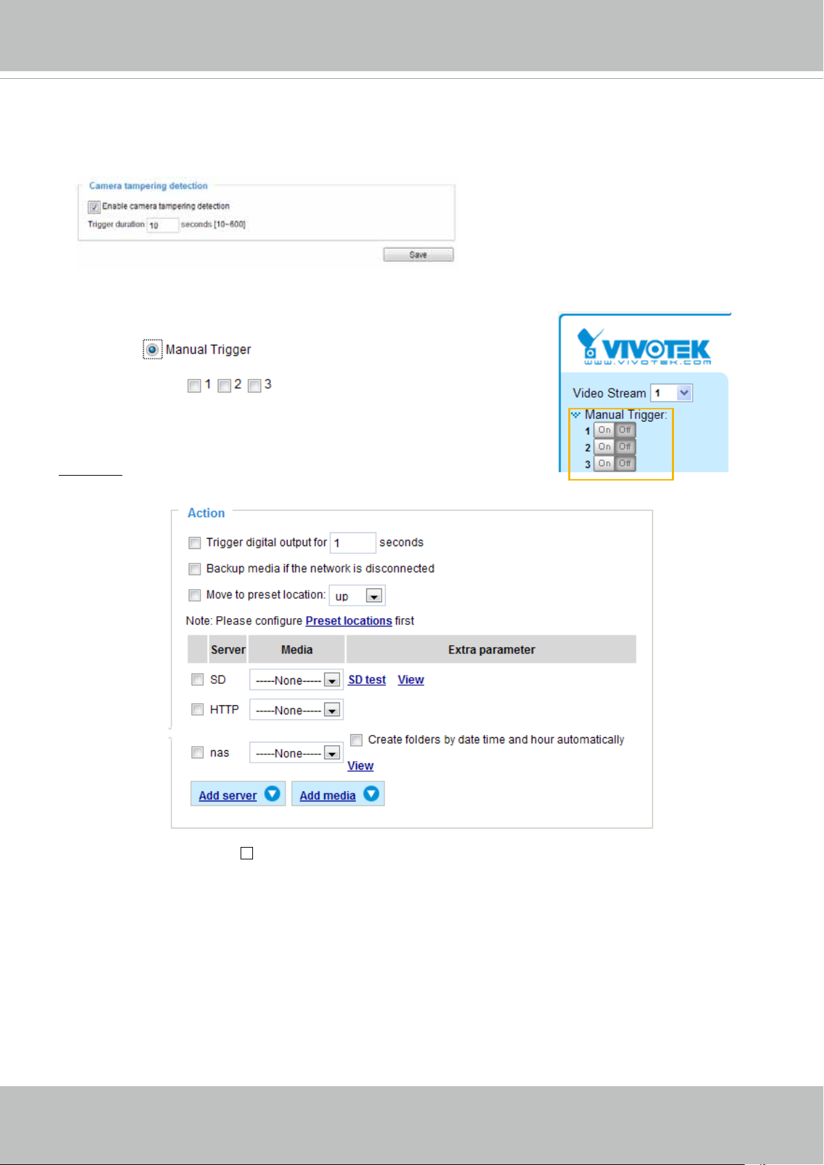
VIVOTEK
■ Camera tampering detection
This option allows the Network Camera to trigger when the camera detects that is is being tampered
with. To enable this function, you need to enable the Tampering Detection function rst. Please refer to
page 111 for detailed information.
■ Manual Trigger
This option allows user to enable event triggers manually by clicking the on/off button on the
homepage. Please congure 1 ~ 3 events before using this function.
3. Action
Dene the actions to be performed by the Network Camera when a trigger is activated.
■ Trigger digital output for seconds
Select this option to turn on the external digital output device when a trigger is activated. Specify the
length of the trigger interval in the text box.
■ Backup media if the network is disconnected
Select this option to backup media le on SD card if the network is disconnected. This function will only
be displayed after you set up a network attached storage (NAS).
■ Move to preset location
Select a preset location you’ve congured. Note that please congure Preset locations rst. To know
more details, please go to page 86.
User's Manual - 97
Page 98
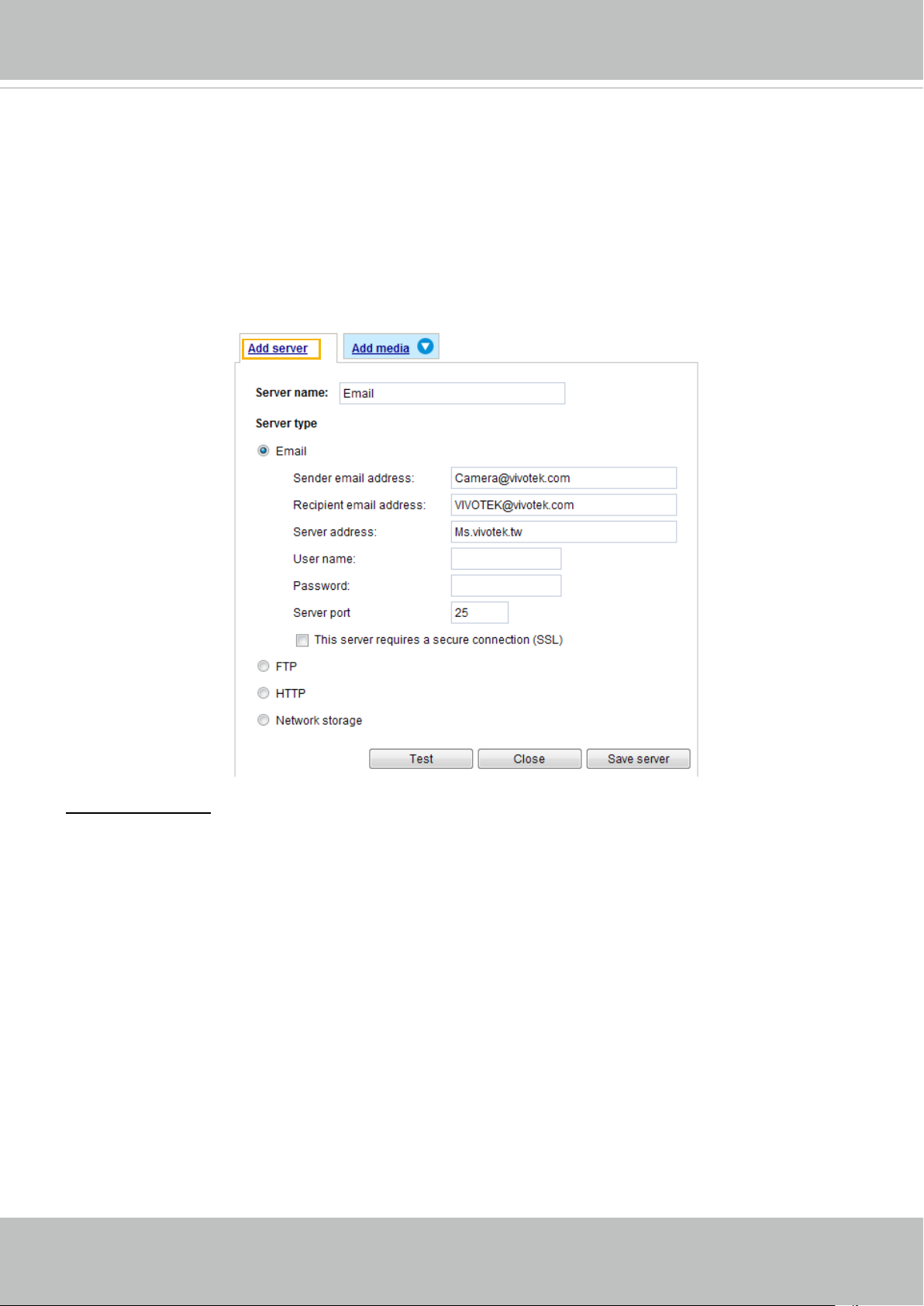
VIVOTEK
Add server
To set an event with recorded video or snapshots, it is necessary to configure the server and media
settings so that the Network Camera will know what action to take (such as which server to send the
media les to) when a trigger is activated. Click
Add server
to open the server setting window. You can
specify where the notication messages are sent when a trigger is activated. A total of 5 server settings
can be congured.
There are four choices of server types available: Email, FTP, HTTP, and Network storage.
to display the detailed conguration options. You can congure either one or all of them.
Select the item
Server type - Email
Select to send the media les via email when a trigger is activated.
■ Server name: Enter a name for the server setting.
■ Sender email address: Enter the email address of the sender.
■ Recipient email address: Enter the email address of the recipient.
■ Server address: Enter the domain name or IP address of the email server.
■ User name: Enter the user name of the email account if necessary.
■ Password: Enter the password of the email account if necessary.
■ Server port: The default mail server port is set to 25. You can also manually set another port.
If your SMTP server requires a secure connection (SSL), check This server requires a secure
connection (SSL).
98 - User's Manual
Page 99
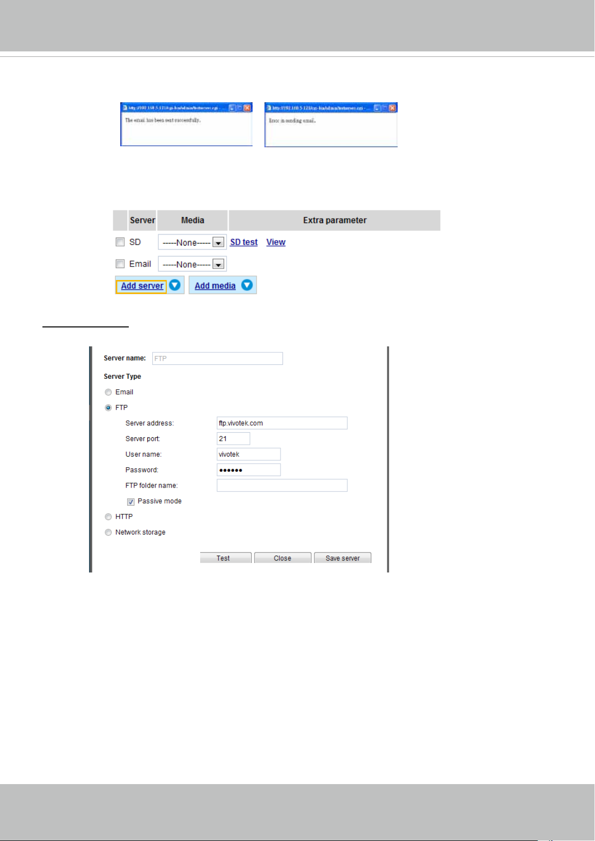
VIVOTEK
To verify if the email settings are correctly congured, click Test. The result will be shown in a pop-up
window. If successful, you will also receive an email indicating the result.
Click Save server to enable the settings.
To note that after you set up the rst event server, a new item for event server will automatically show up
on the Server list. If you wish to add other server options, click Add server.
Server type - FTP
Select to send the media les to an FTP server when a trigger is activated.
■ Server name: Enter a name for the server setting.
■ Server address: Enter the domain name or IP address of the FTP server.
■ Server port: By default, the FTP server port is set to 21. It can also be assigned to another port number
between 1025 and 65535.
■ User name: Enter the login name of the FTP account.
■ Password: Enter the password of the FTP account.
■ FTP folder name
Enter the folder where the media le will be placed. If the folder name does not exist, the Network
Camera will automatically create one on the FTP server.
User's Manual - 99
Page 100
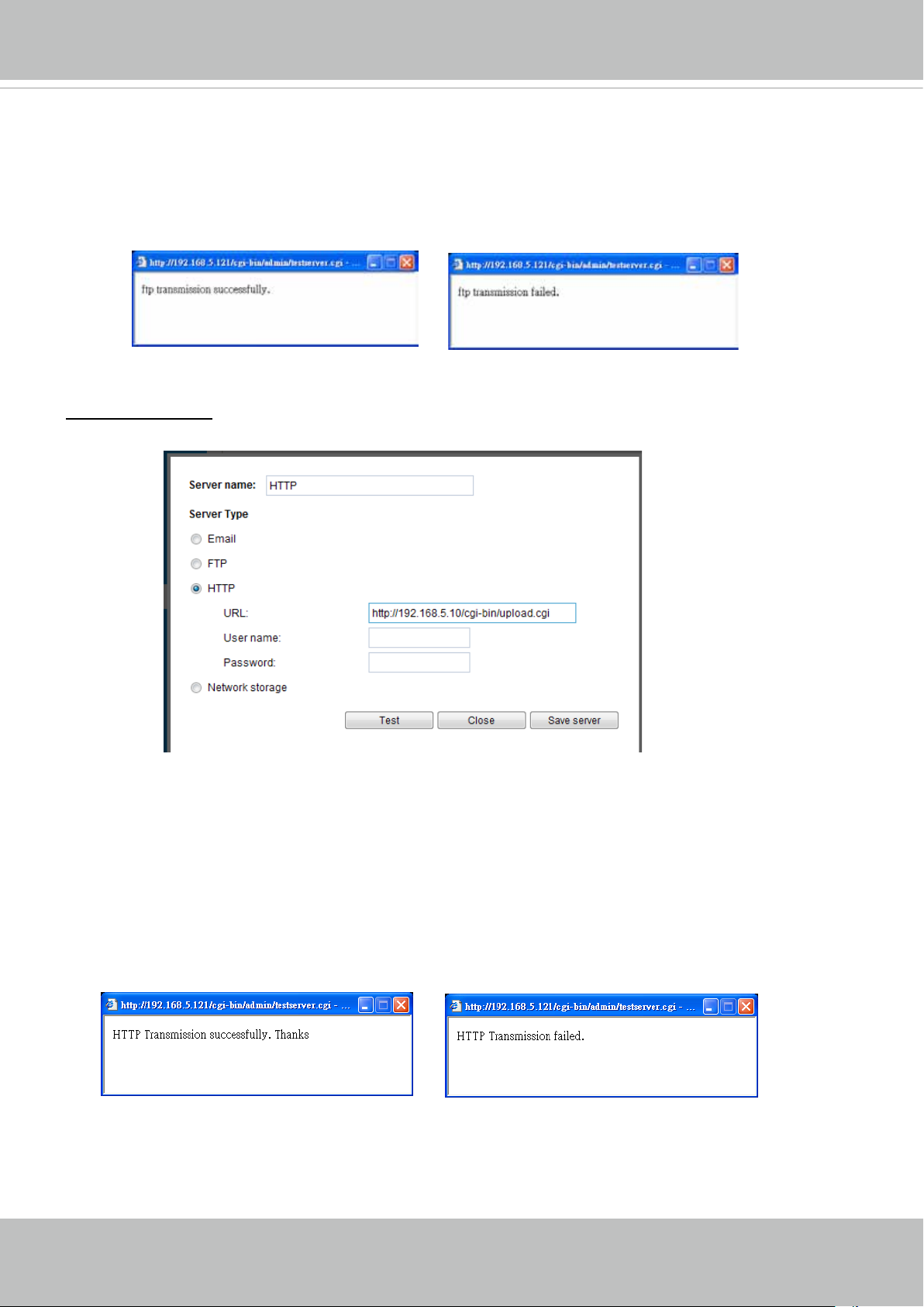
VIVOTEK
■ Passive mode
Most firewalls do not accept new connections initiated from external requests. If the FTP server
supports passive mode, select this option to enable passive mode FTP and allow data transmission to
pass through the rewall.
To verify if the FTP settings are correctly congured, click Test. The result will be shown in a pop-up
window as shown below. If successful, you will also receive a test.txt le on the FTP server.
Click Save server to enable the settings.
Server type - HTTP
Select to send the media les to an HTTP server when a trigger is activated.
■ Server name: Enter a name for the server setting.
■ URL: Enter the URL of the HTTP server.
■ User name: Enter the user name if necessary.
■ Password: Enter the password if necessary.
To verify if the HTTP settings are correctly congured, click Test. The result will be shown in a pop-up
window as below. If successful, you will receive a test.txt le on the HTTP server.
Click Save server to enable the settings.
100 - User's Manual
 Loading...