

Vivotek IP8371E Installation Guide
Warning Before Installation
English
Power off the Network Camera as
soon as smoke or unusual odors are
detected.
Do not place the Network Camera on
unsteady surfaces.
Do not insert sharp or tiny objects
into the Network Camera.
1
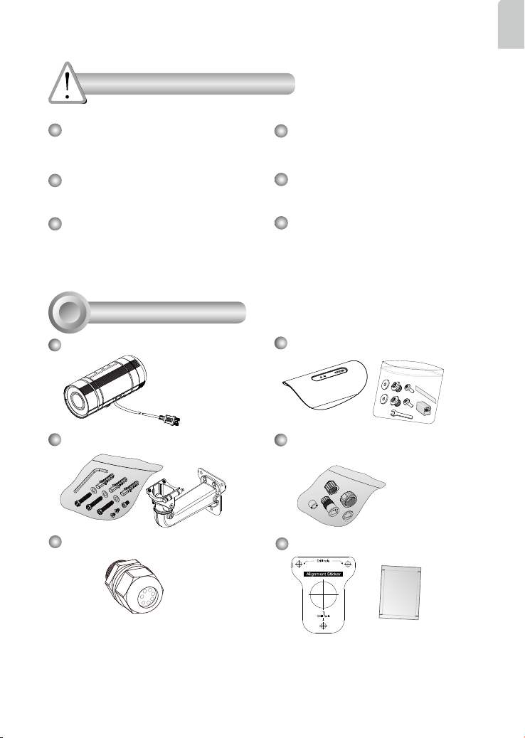
Package Contents
IP8371E with an RJ45 Cable
Wall Mount Bracket
Refer to your user's manual for the
operating temperature.
Do not touch the Network Camera
during a lightning storm.
Do not drop the Network Camera.
Sun Shield / Wrench / RJ45 Female /
Female Coupler / Double-sided Tape / Screws
Waterproof Connector for RJ45
Ethernet Enclosure
Waterproof Connector (for backup
use)
Alignment Sticker / Desiccant Bag
EN-1
5
1
0
0
0
0
2
2
1
G
Quick Installation Guide
Network Bullet Camera
IP8371E
Quick Installation Guide
Türkçe
繁中 日本語
簡中
ČeskySvenska
Русский
Italiano
Deutsch
Français
Polski
English
Español Português
2MP • Outdoor • Day & Night
Cable Management
Warranty Card
2
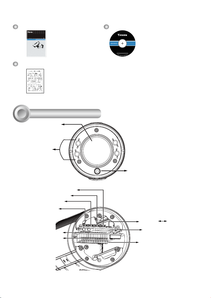
Physical Description
Lens
IR LEDs
Zoom out
Zoom in
Auto Focus
Reset Button
Red LED
Green LED
Software CD
Light Sensor
NTSC-PAL switch
NTSC
PAL
SD/SDHC/SDXC Card
Slot
General I/O Terminal
Block
EN-2
3
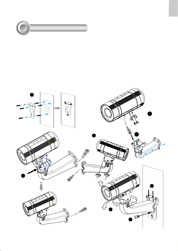
Hardware Installation
1. Attach the alignment sticker to the wall. Drill four holes into the wall. Then hammer the supplied
plastic anchors into the holes and secure the plate with supplied screws.
2. Fix the intersection bracket to the side of the Network Camera with two screws.
3. Feed the RJ45 cable through the front opening of the wall mount bracket. (If you want to use
external devices such as sensors and alarms, please refer to the assembling steps on the next
page.)
4. Push the spring mortise and hook the bracket onto the groove of the wall mount bracket.
5. Secure the two screws on the other side of the wall mount bracket.
6. Hang the wall mount bracket to the mounting plate.
7. Fix the wall mount bracket with the supplied screw.
8. Adjust the angle of the wall mount bracket to aim at the shooting area.
1
2
English
5
4
8
3
6
7
EN-3
 Loading...