


IB9360-H
IB9380-H
Bullet Network Camera
User’s Manual
5MP/2MP • Outdoor • IP66 • IK10 • Day & Night
WDR Pro • Smart Stream III • 30M Smart IR
Rev. 1.0

VIVOTEK
Table of Contents
Overview
Revision History ..................................................................................................................................................... 4
Read Before Use .................................................................................................................................................... 4
Package Contents .................................................................................................................................................. 5
Symbols and Statements in this Document ............................................................................................................ 5
Physical Description .............................................................................................................................................. 6
Hardware Installation ............................................................................................................................................. 8
Software Installation ............................................................................................................................................. 14
Network Deployment ............................................................................................................................................ 21
Ready to Use ........................................................................................................................................................ 22
Accessing the Network Camera
Using Web Browsers ............................................................................................................................................ 25
Using RTSP Players ............................................................................................................................................. 28
Using 3GPP-compatible Mobile Devices .............................................................................................................. 29
Using VIVOTEK Recording Software ................................................................................................................... 30
Main Page
Client Settings
Conguration
System > General settings ................................................................................................................................... 42
System > Homepage layout ................................................................................................................................ 44
System > Logs ..................................................................................................................................................... 47
System > Parameters .......................................................................................................................................... 49
System > Maintenance ......................................................................................................................................... 50
Media > Image ................................................................................................................................................... 54
Media > Video ...................................................................................................................................................... 66
Media > Video ...................................................................................................................................................... 67
Media > Video ...................................................................................................................................................... 68
Network > General settings .................................................................................................................................. 77
Network > Streaming protocols .......................................................................................................................... 84
Network > SNMP
Network > FTP ..................................................................................................................................................... 94
Security > User accounts ..................................................................................................................................... 95
Security > HTTPS
Security > Access List ...................................................................................................................................... 104
PTZ > PTZ settings ............................................................................................................................................ 110
Event > Event settings........................................................................................................................................ 114
Applications > Motion detection.......................................................................................................................... 128
Applications > Tampering detection ................................................................................................................... 131
Applications > Package management - a.k.a., VADP (VIVOTEK Application Development Platform) ............. 132
Recording > Recording settings ........................................................................................................................ 135
Local storage > SD card management ............................................................................................................... 140
Local storage > Content management ............................................................................................................... 141
Appendix
URL Commands for the Network Camera .......................................................................................................... 144
....................................................................................................................................................................
...........................................................................................................................
................................................................................................................................................................
.........................................................................................................................................................
...........................................................................................................................................................
(Simple Network Management Protocol) ................................................................... 93
(Hypertext Transfer Protocol over SSL)
...............................................................................................................................................................
............................................................... 97
3
25
31
36
41
144
2 - User's Manual

VIVOTEK
Technology License Notice ....................................................................................................................... 397
Electromagnetic Compatibility (EMC) .......................................................................................................398
Overview
The IB9360 and IB9380 is an outdoor bullet network camera capable of 1920 x 1080 at 30
fps, or 2560 x 1920 resolution at 20 fps. At the 5MP resolution and with the WDR function
enabled, the frame rate is slightly reduced to 20fps. The firmware comes with another
4MP resolution mode with a 30fps frame rate. With the most updated VIVOTEK WDR Pro
technology, the camera series is capable of capturing the highest quality images in both
low light and high contrast environments.
The onboard IR can provide illumination in total darkness. With the Smart IR feature, the
rmware automatically adjust the IR intensity for objects that came too close, in order to
avoid over-exposure.
The camera also offers the best in night time surveillance technology. By adopting Smart
IR II technology from VIVOTEK speed domes, the camera’s IR illuminators now align with
the remote focus lens’ focus angle to provide the best IR image quality at any lens setting.
This feature optimizes IR intensity, reduces IR hotspots, and increases the IR effective
range up to 30 meters.
User's Manual - 3

VIVOTEK
Revision History
■ Rev. 1.0: Initial release.
Read Before Use
The use of surveillance devices may be prohibited by law in your country. The Network Camera
is not only a high-performance web-ready camera but can also be part of a exible surveillance
system. It is the user’s responsibility to ensure that the operation of such devices is legal before
installing this unit for its intended use.
It is important to first verify that all contents received are complete according to the Package
Contents listed below. Take note of the warnings in the Quick Installation Guide before the Network
Camera is installed; then carefully read and follow the instructions in the Installation chapter to
avoid damage due to faulty assembly and installation. This also ensures the product is used
properly as intended.
The Network Camera is a network device and its use should be straightforward for those who
have basic networking knowledge. It is designed for various applications including video sharing,
general security/surveillance, etc. The Configuration chapter suggests ways to best utilize the
Network Camera and ensure proper operations. For creative and professional developers, the URL
Commands of the Network Camera section serves as a helpful reference to customizing existing
homepages or integrating with the current web server.
4 - User's Manual

i
Package Contents
■ IB9360-H or IB9380-H
■ Screw pack and side lid.
■ Alignment sticker.
■ Quick Installation Guide.
■ Waterproof cable gland.
WARNING:
1. IR lights emit from this product.
2. Use appropriate shielding or eye protection.
Symbols and Statements in this Document
VIVOTEK
INFORMATION: provides important messages or advices that might help prevent
inconvenient or problem situations.
NOTE: Notices provide guidance or advices that are related to the functional integrity of
the machine.
Tips: Tips are useful information that helps enhance or facilitae an installation, function,
or process.
WARNING: or IMPORTANT:: These statements indicate situations that can be
dangerous or hazardous to the machine or you.
Electrical Hazard: This statement appears when high voltage electrical hazards might
occur to an operator.
IMPORTANT:
1. The camera is only to be connected to PoE networks without routing to outside plants.
2. For PoE connection, use only UL listed I.T.E. with PoE output.
1. La caméra ne doit être raccordée qu’à des réseaux PoE, sans routage vers des
installations extérieures.
2. Pour les raccordements PoE, utilisez uniquement un équipement de TI homologué UL,
avec une sortie PoE.
Use the camera only with a DC power supply that is UL listed, and limited power source
(LPS) certied. The power supply should bear the UL listed and LPS marks. The power
supply should also meet any safety and compliance requirements for the country of use.
n’utilisez la caméra qu’avec un bloc d’alimentation CC homologué UL, ainsi qu’avec
une alimentation limitée (LPS) certiée. Le bloc d’alimentation doit porter les indications
d'homologation UL et LPS. Il doit également répondre aux exigences en matière de
sécurité et de conformité relatives au pays d’utilisation.
User's Manual - 5
VIVOTEK
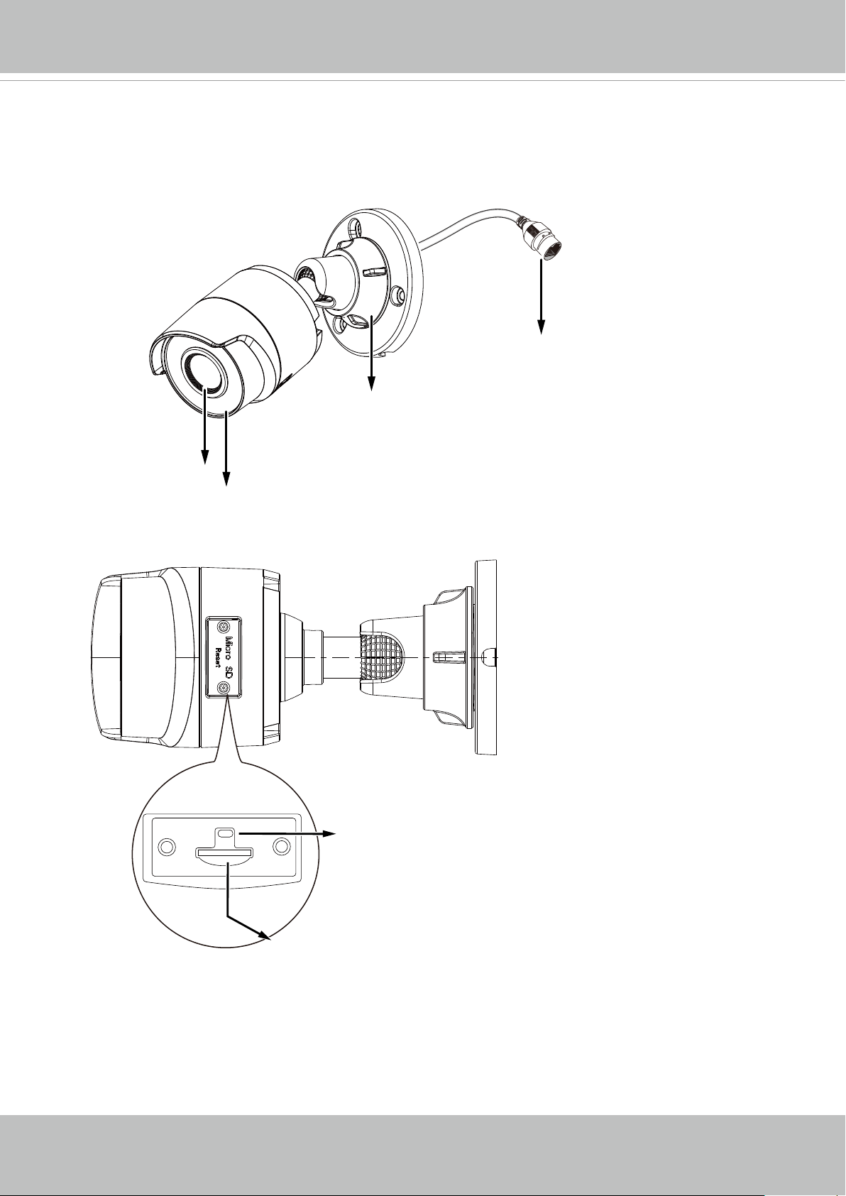
Physical Description
Outer View
RJ45 Ethernet connector
Fastening ring
Inner View
Lens
IR LEDs
Reset button
6 - User's Manual
MicroSD card slot

NOTE:
Some of the sufx syntax used in model naming are listed below:
E w/ heater for extreme weather
Fx Focal length w/ number
T w/ Remote focus lens
R w/ PoE repeater
H w/ High Dynamic Range functionality
VIVOTEK
User's Manual - 7

VIVOTEK
Hardware Installation
1. Jot down the camera's MAC address for later reference.
XXXXXX
0002D10766AD
2. Open the small hatch cover by loosening the T10 anti-tamper screws. Install a MicroSD
card if onboard storage is preferred.
T10
8 - User's Manual
64
GB
10
1
I

3. Use the alignment sticker to drill mounting holes on the wall or ceiling. Drill a cabling
routing hole if preferred.
VIVOTEK
Ø ≥25mm
4. Route an Ethernet cable through the cabling hole.
User's Manual - 9
VIVOTEK
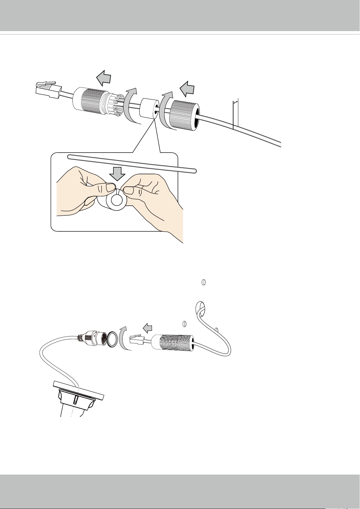
5. Pass an Ethernet cable through the waterproof cable gland components, and through
the rubber seal as shown below. Connect the Ethernet cable to the camera's RJ45
connector.
5.5 ~ 6.4mm
6. Install the seal ring and tighten the waterproof components.
10 - User's Manual
VIVOTEK
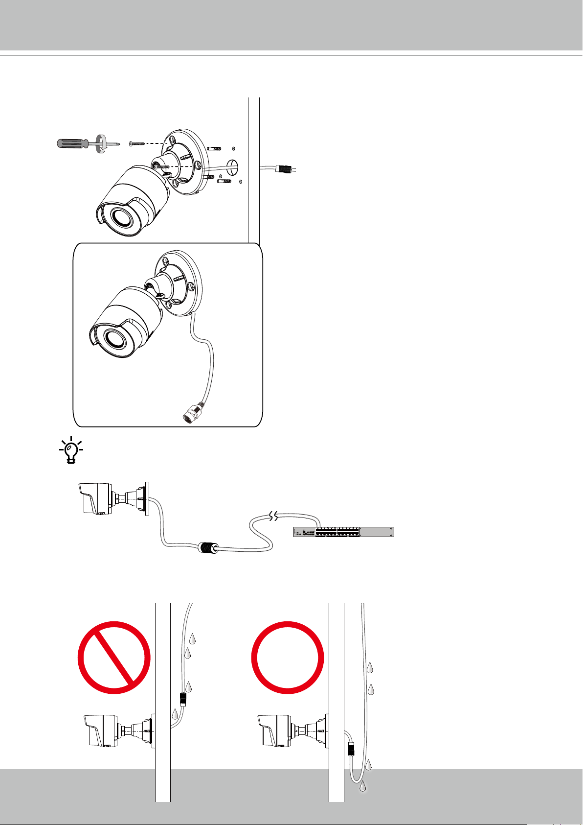
7. Install the camera to wall using the included screws. Note that if a routing hole through
the wall is not possible, you can also route the cable through the side opening.
< 10 kgf-cm
Note that it is always a good practice to form a drip loop of cables. Moisture
condensation or dripping water can eventually cause problems without the drip
loop.
PoE
User's Manual - 11

VIVOTEK
8. Connect a ground wire to the grounding position at the back of the camera using the
included screw.
20AWG
9. Remove the protective sheet from the front of the lens.
12 - User's Manual
VIVOTEK
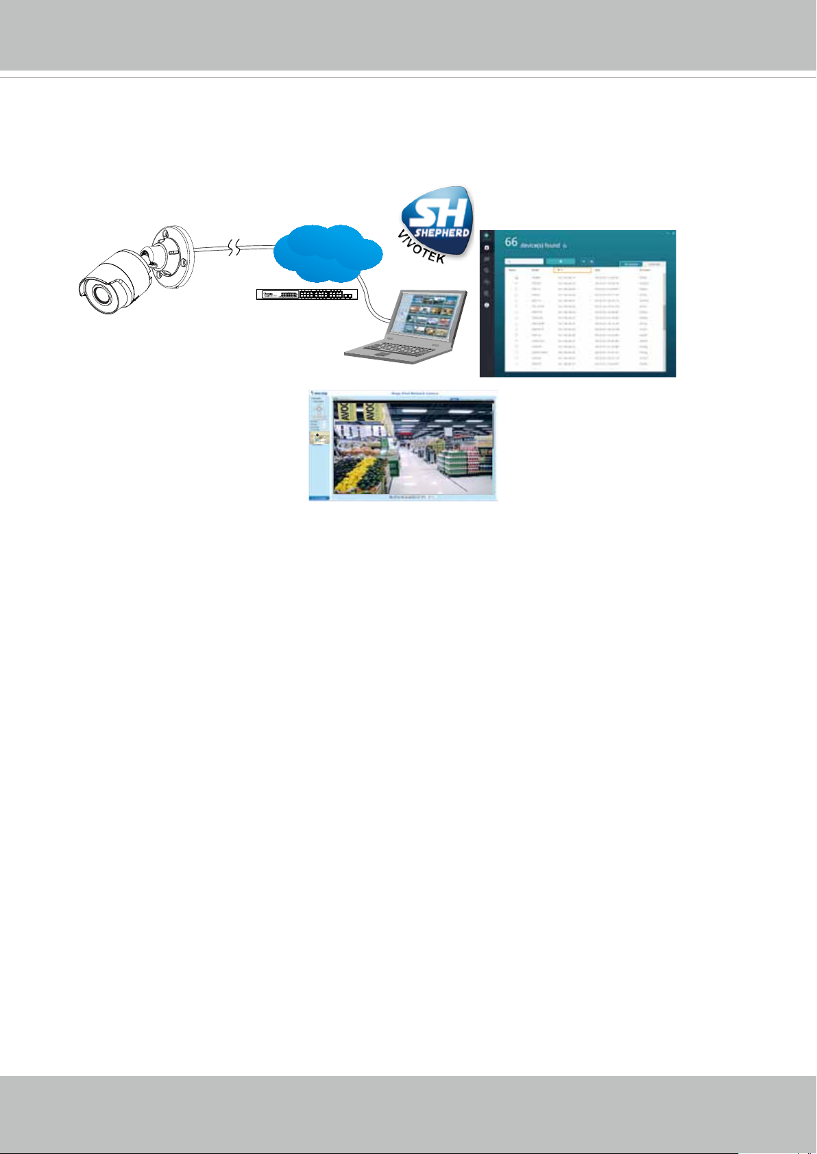
10. Please visit VIVOTEK’s website to Install the "Shepherd” software utility. The program
will search for VIVOTEK Video Receivers, Video Servers or Network Cameras on the
same LAN.
Double-click on the camera’s MAC address to open a web console to the camera.
Shepherd
LAN
IEEE 802.3af
Browser
User's Manual - 13
VIVOTEK
Software Installation
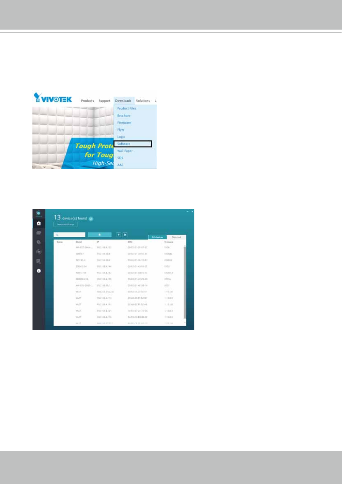
11. Install the Shepherd utility, which helps you locate and congure your Network Camera
in the local network. If your camera comes without the CD, go to VIVOTEK’s website,
and locate the utility in the Downloads > Software page.
11-1. Run the Shepherd utility.
11-2. The program will conduct an analysis of your network environment.
14 - User's Manual
VIVOTEK
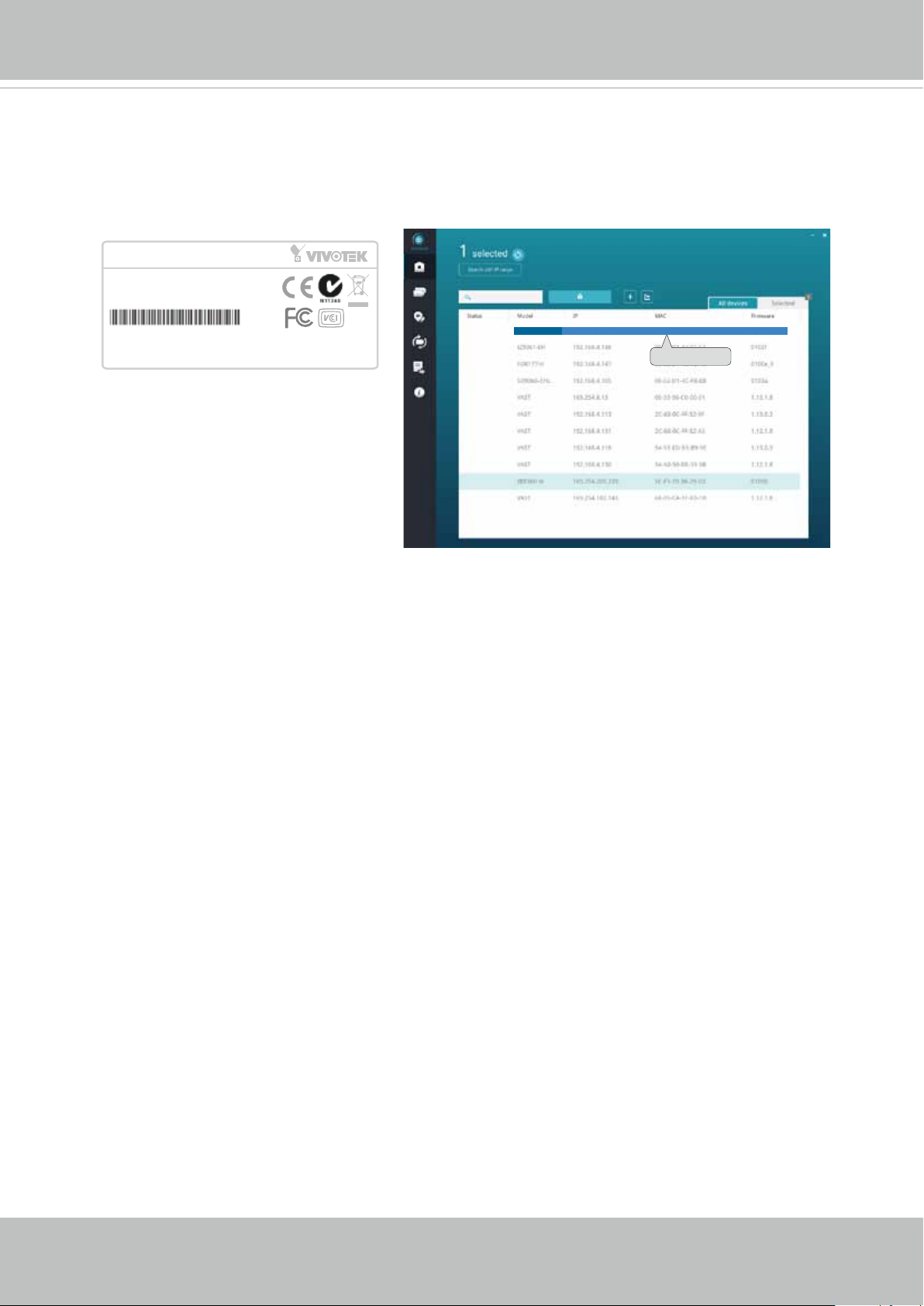
11-3. The program will search for all VIVOTEK network devices on the same LAN.
11-4. After a brief search, the installer window will prompt. Click on the MAC and model
name that matches the one printed on the product label. You can then double-click on
the address to open a management session with the Network Camera.
Network Camera
Model No: IB9360-H
MAC:0002D1730202
This device complies with part 15 of the FCC rules. Operation is subject to the following two conditions:
(1)This device may not cause harmful interference, and
(2) this device must accept any interference received, including interference that may cause undesired operation.
Pat. 6,930,709
R o HS
Made in Taiwan
IB9360-H
IB8360-W 192.168.4.151 00-02-D1-73-02-02
0002D1730202
User's Manual - 15

VIVOTEK
Forceful Password Conguration
12. The first time you log in to the camera, the firmware will prompt for a password
conguration for security concerns.
12-1. Since your camera is used for the rst time, there is no password. Enter “root” as the
user name, and nothting for the password.
12-2. Enter the combination of alphabetic and numeric characters to fulll the password
strength. requirement. The default name for the camera administrator is “root”, and can
not be changed.
16 - User's Manual

VIVOTEK
Some, but not all special ASCII characters are supported: !, $, %, -, ., @, ^, _, and ~.
You can use them in the password combination.
12-3. Another prompt will request for the password you just congured. Enter the password
and then you can start congure your camera and see the live view.
User's Manual - 17

VIVOTEK
13. Loosen the fastening ring.
14. Pan, tilt, or rotate the camera until an optimal field of view is found.
18 - User's Manual

15. Fasten the fastening ring when you are satisfied with the field of view.
VIVOTEK
User's Manual - 19

VIVOTEK
Hardware Reset
The reset button is used to reset the system or restore the factory default settings.
Sometimes resetting the system can return the camera to normal operation. If the system
problems remain after reset, restore the factory settings and install again.
Reset: Press the recessed reset button. Wait for the Network Camera to reboot.
Restore: Press and hold the reset button until the status LED rapidly blinks. Note that all
settings will be restored to factory default. Upon successful restore, the status LED will
blink green and red during normal operation.
MicroSD/SDHC/SDXC Card Capacity
This network camera is compliant with SD/SDHC/SDXC 16GB / 8GB / 32GB / 64GB and
other preceding standard SD cards.
20 - User's Manual
Network Deployment
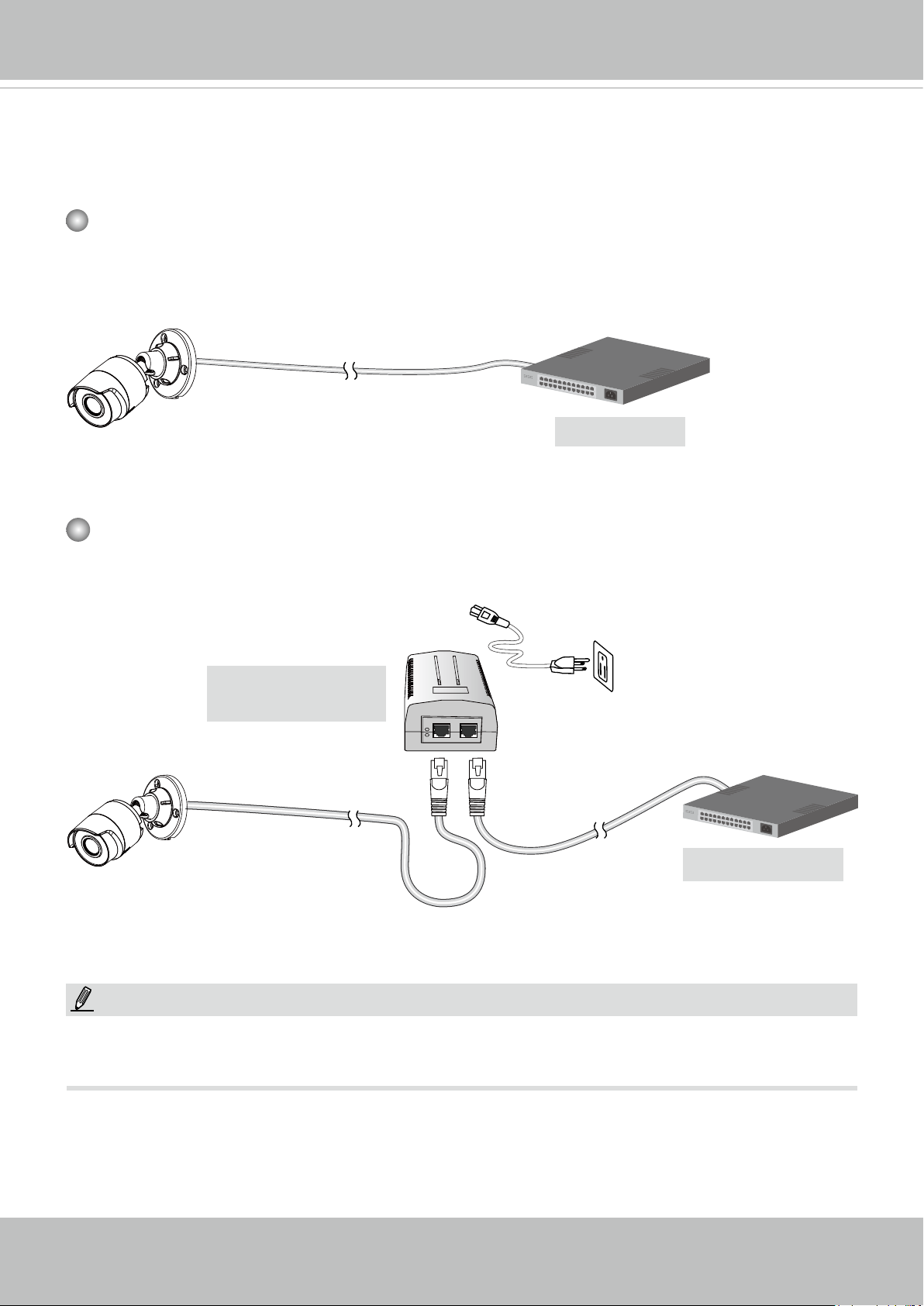
General Connection (PoE)
When using a PoE-enabled switch
The Network Camera is PoE-compliant, allowing transmission of power and data via a single Ethernet cable. Follow the below illustration to connect the Network Camera to a PoEenabled switch via an Ethernet cable.
VIVOTEK
802.3af
PoE Switch
When using a non-PoE switch
Use a PoE power injector (optional) to connect between the Network Camera and a non-
PoE switch.
PoE Power Injector
(optional)
Non-PoE Switch
NOTE:
1. The camera is only to be connected to PoE networks without routing to outside plants.
2. For PoE connection, use only UL listed I.T.E. with PoE output.
User's Manual - 21

VIVOTEK
Ready to Use
1. A browser session to the Network Camera should prompt as shown below.
2. You should be able to see live video from your camera. You may also install the
32-channel recording software from the software CD in a deployment consisting of
multiple cameras. For its installation details, please refer to its related documents.
22 - User's Manual
VIVOTEK
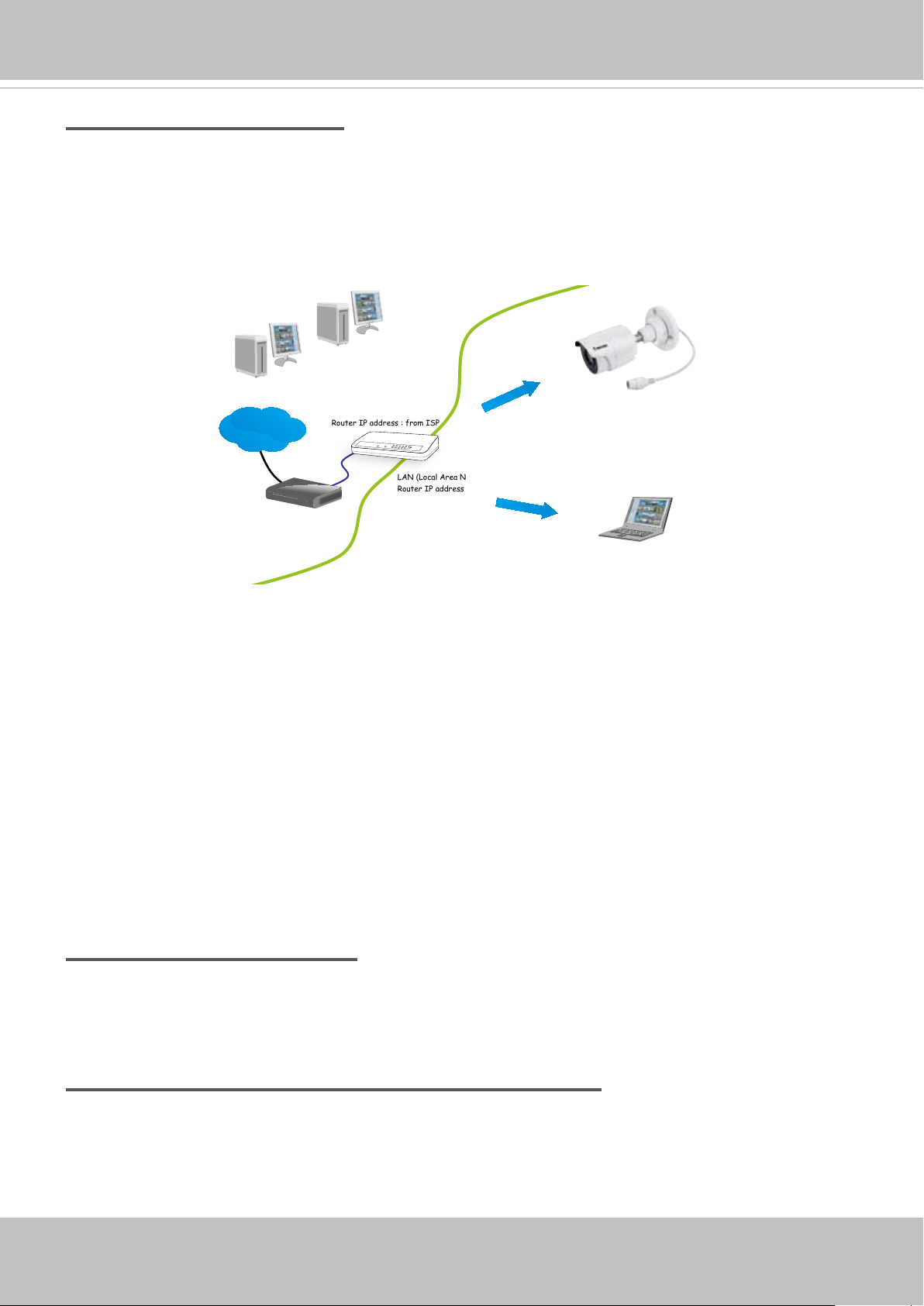
Internet connection via a router
Before setting up the Network Camera over the Internet, make sure you have a router and follow
the steps below.
1. Connect your Network Camera behind a router, the Internet environment is illustrated below.
Regarding how to obtain your IP address, please refer to Software Installation on page 20 for
details.
IP address : 192.168.0.3
Subnet mask : 255.255.255.0
Default router : 192.168.0.1
IP address : 192.168.0.2
Subnet mask : 255.255.255.0
Default router : 192.168.0.1
Internet
Cable or DSL Modem
WAN (Wide Area Network )
Router IP address : from ISP
LINK
POWER
COLLISION
RECEIVE
1
2
PARTITION
3
4
5
LAN (Local Area Network)
Router IP address : 192.168.0.1
2. In this case, if the Local Area Network (LAN) IP address of your Network Camera is
192.168.0.3, please forward the following ports for the Network Camera on the router.
■ HTTP port: default is 80
■ RTSP port: default is 554
■ RTP port for video: default is 5556
■ RTCP port for video: default is 5557
If you have changed the port numbers on the Network page, please open the ports
accordingly on your router. For information on how to forward ports on the router, please refer
to your router’s user’s manual.
3. Find out the public IP address of your router provided by your ISP (Internet Service Provider).
Use the public IP and the secondary HTTP port to access the Network Camera from the
Internet. Please refer to Network Type on page 78 for details.
Internet connection with static IP
Choose this connection type if you are required to use a static IP for the Network Camera.
Please refer to LAN setting on page 77 for details.
Internet connection via PPPoE (Point-to-Point over Ethernet)
Choose this connection type if you are connected to the Internet via a DSL Line. Please refer to
PPPoE on page 78 for details.
User's Manual - 23
VIVOTEK
For example, your router and IP settings may look like this:
Device IP Address: internal port IP Address: External Port (Mapped
port on the router)
Public IP of router 122.146.57.120
LAN IP of router 192.168.2.1
Camera 1 192.168.2.10:80 122.146.57.120:8000
Camera 2 192.168.2.11:80 122.146.57.120:8001
... ... ...
Congure the router, virtual server or rewall, so that the router can forward any data coming into a precongured port number to a network camera on the private network, and
allow data from the camera to be transmitted to the outside of the network over the same
path.
From Forward to
122.146.57.120:8000 192.168.2.10:80
122.146.57.120:8001 192.168.2.11:80
... ...
When properly congured, you can access a camera behind the router using the HTTP
request as follows: http://122.146.57.120:8000
If you change the port numbers on the Network conguration page, please open the ports
accordingly on your router. For example, you can open a management session with your
router to congure access through the router to the camera within your local network.
Please consult your network administrator for router conguration if you have troubles with
the conguration.
For more information with network conguration options (such as that of streaming ports),
please refer to Conguration > Network Settings. VIVOTEK also provides the automatic
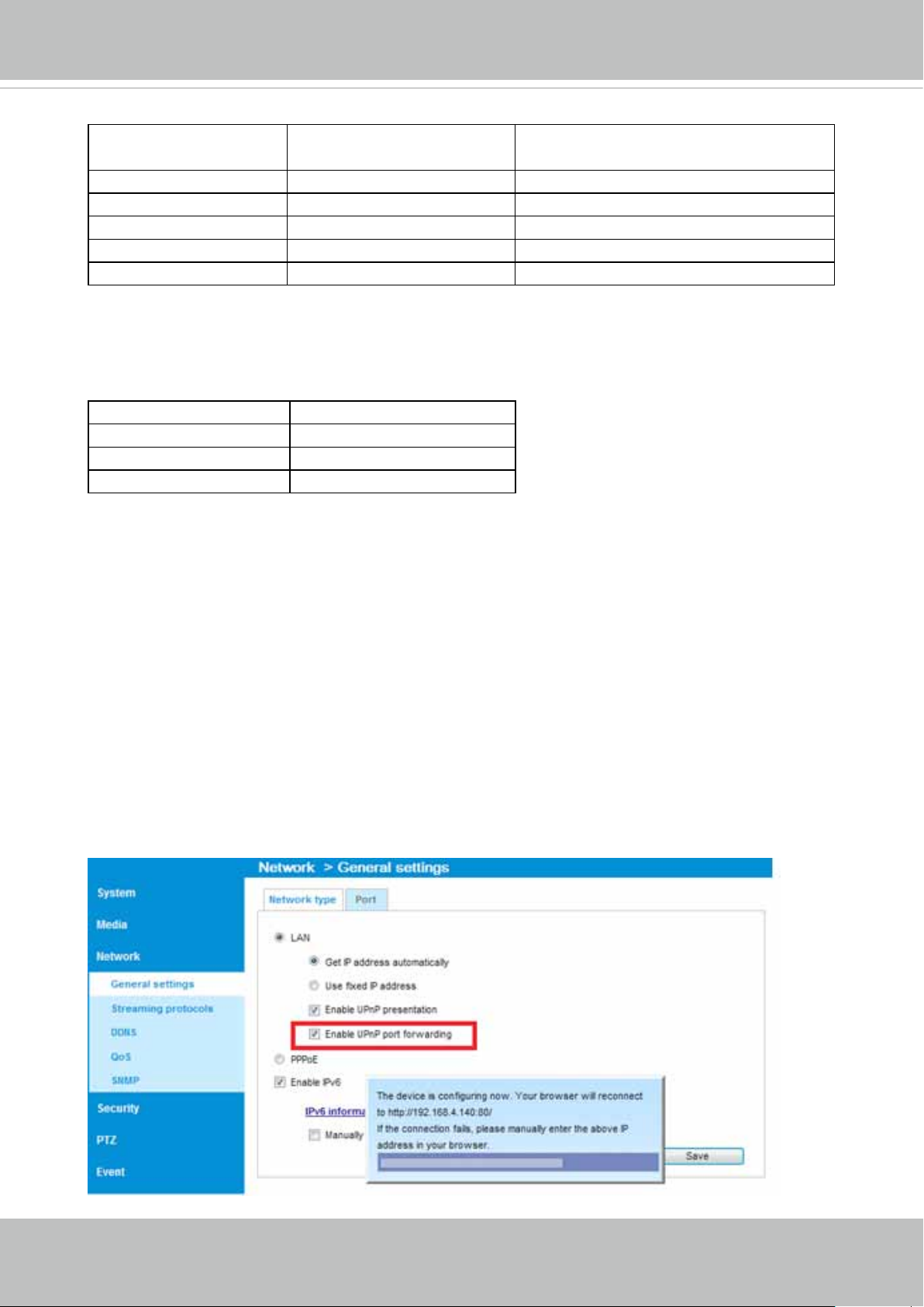
port forwarding feature as an NAT traversal function with the precondition that your router
must support the UPnP port forwarding feature.
24 - User's Manual
VIVOTEK
Accessing the Network Camera
This chapter explains how to access the Network Camera through web browsers, RTSP players,
3GPP-compatible mobile devices, and VIVOTEK recording software.
Using Web Browsers
Use Installation Wizard 2 (IW2) to access the Network Cameras on LAN.
If your network environment is not a LAN, follow these steps to access the Netwotk Camera:
1. Launch your web browser (e.g., Microsoft
2. Enter the IP address of the Network Camera in the address eld. Press Enter.
3. Live video will be displayed in your web browser.
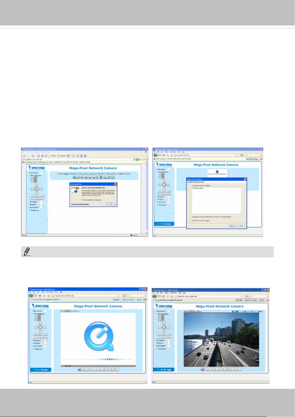
4. If it is the rst time installing the VIVOTEK network camera, an information bar will prompt as
shown below. Follow the instructions to install the required plug-in on your computer.
®
Internet Explorer or Mozilla Firefox).
NOTE:
NOTE
► For Mozilla Firefox or Chrome users, your browser will use QuickTime to stream the live
video. If you don’t have QuickTime on your computer, please download it rst, then launch
the web browser.
User's Manual - 25
VIVOTEK
► By default, the Network Camera is not password-protected. To prevent unauthorized access,
it is highly recommended to set a password for the Network Camera.
For more information about how to enable password protection, please refer to Security on
page 95.
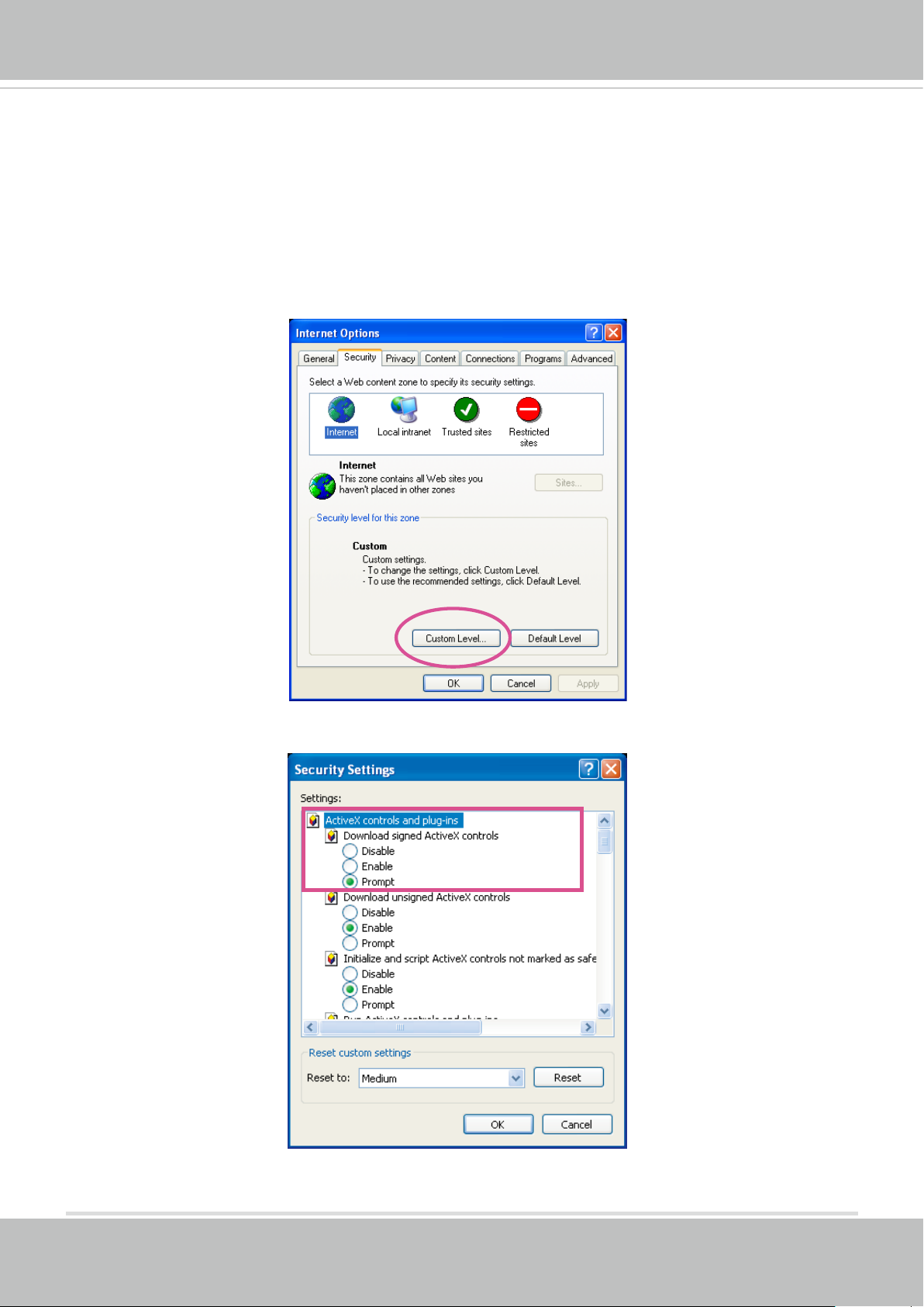
► If you see a dialog box indicating that your security settings prohibit running ActiveX
®
Controls, please enable the ActiveX
Controls for your browser.
®
1. Choose Tools > Internet Options > Security > Custom Level.
2. Look for Download signed ActiveX
®
controls; select Enable or Prompt. Click OK.
3. Refresh your web browser, then install the ActiveX
complete installation.
®
control. Follow the instructions to
26 - User's Manual
VIVOTEK
IMPORTANT:
Currently the Network Camera utilizes a 32-bit ActiveX plugin. You CAN NOT open a
•
management/view session with the camera using a 64-bit IE browser.
If you encounter this problem, try execute the Iexplore.exe program from C:\Windows\
•
SysWOW64. A 32-bit version of IE browser will be installed.
On Windows 7, the 32-bit explorer browser can be accessed from here:
•
C:\Program Files (x86)\Internet Explorer\iexplore.exe
If you open a web session from the Shepherd utility, a 32-bit IE browser will be
•
opened.
Tips:
1. The onscreen Java control can malfunction under the following situations: A PC con-
nects to different cameras that are using the same IP address (or the same camera
running different rmware versions). Removing your browser cookies will solve this
problem.
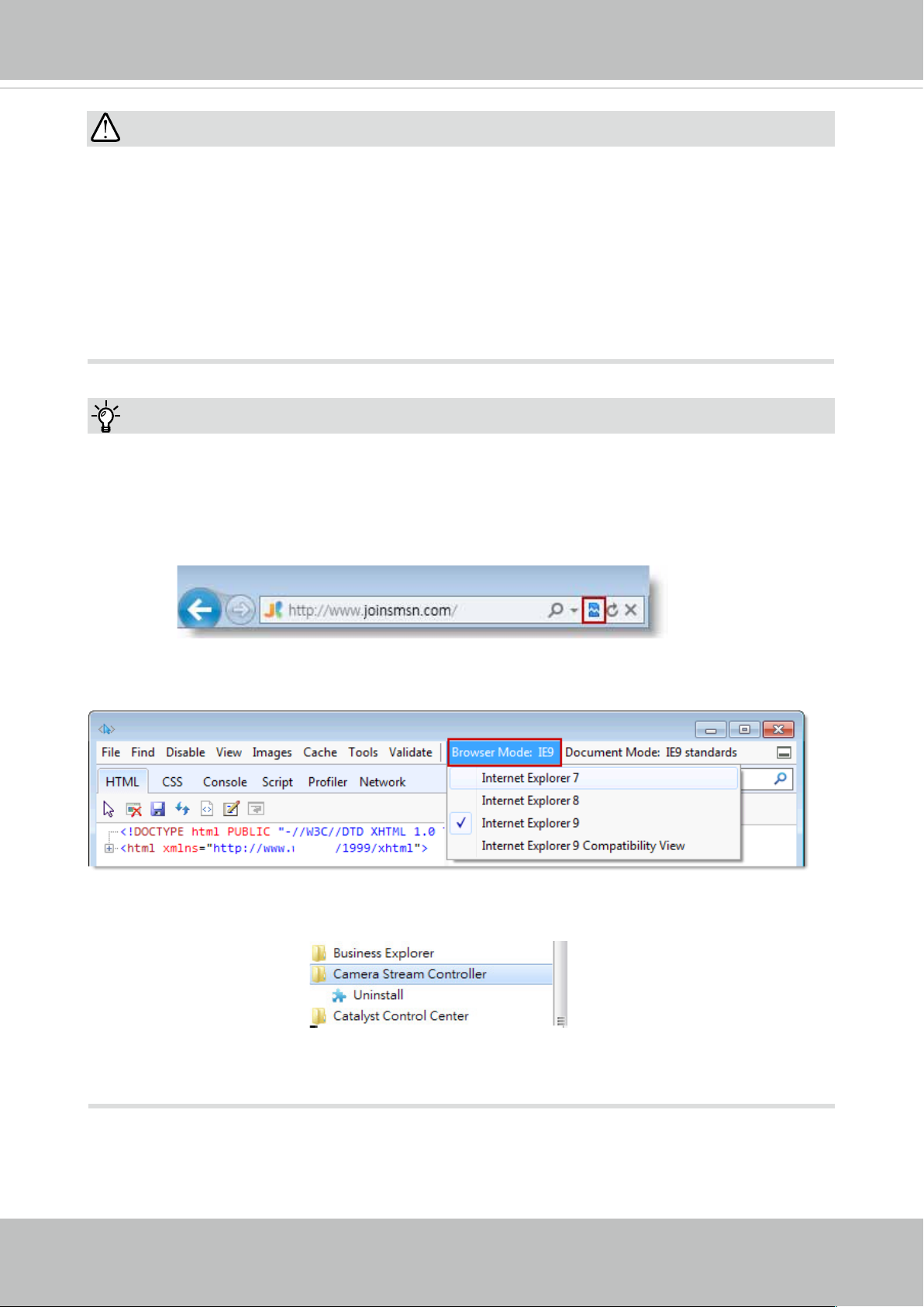
2. If you encounter problems with displaying the conguration menus or UI items, try dis-
able the Compatibility View on IE8 or IE9.
You may also press the F12 key to open the developer tools utility, and then change the
Browser Mode to the genuine IE8 or IE9 mode.
• In the event of plug-in compatibility issues, you may try to uninstall the plug-in that was
previously installed.
User's Manual - 27

VIVOTEK
Using RTSP Players
To view the streaming media using RTSP players, you can use one of the following players that
support RTSP streaming.
Quick Time Player
VLC media player
VLC media player
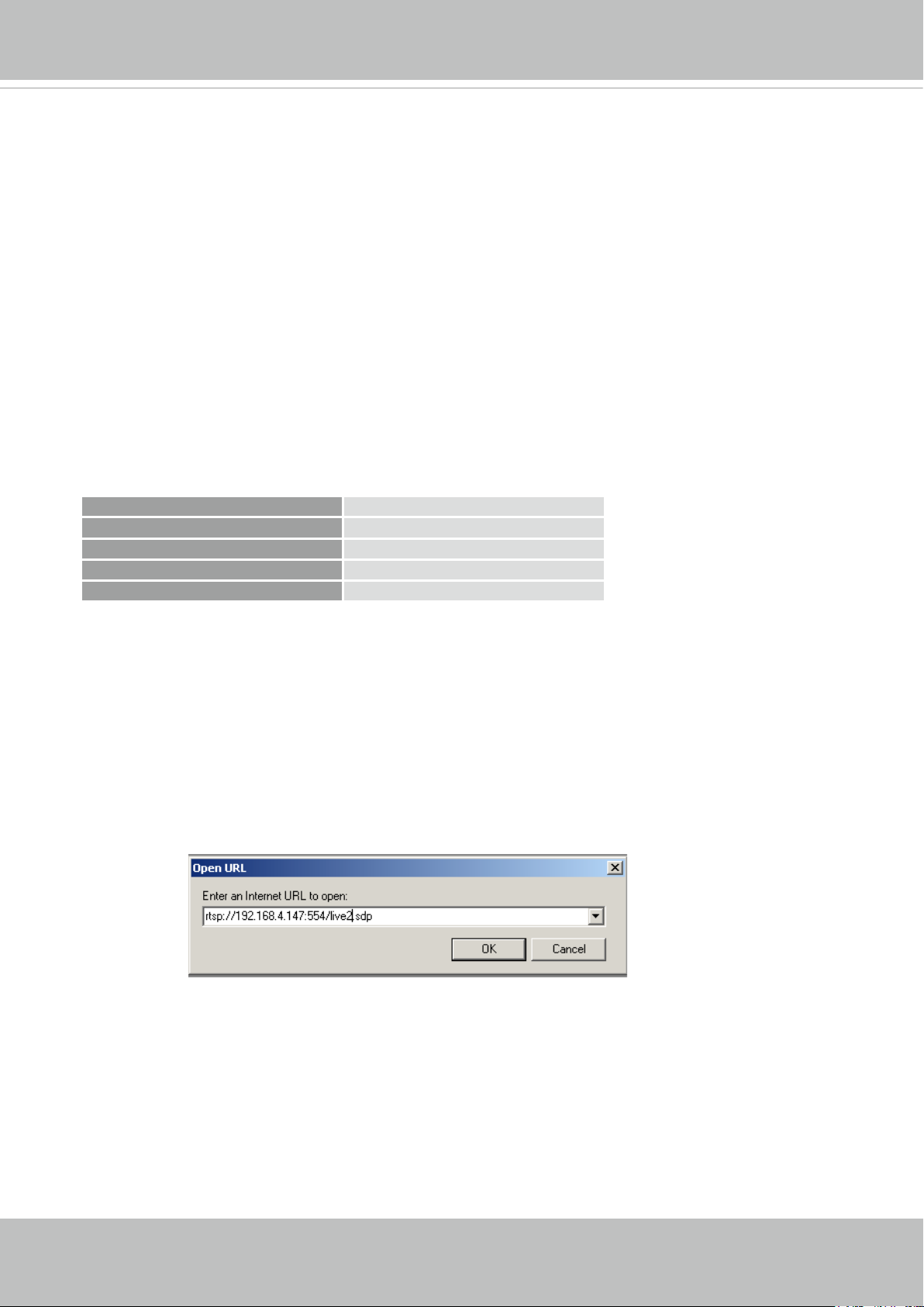
1. Launch the RTSP player.
mpegable Player
2. Choose File > Open URL. A URL dialog box will pop up.
3. The address format is rtsp://<ip address>:<rtsp port>/<RTSP streaming access name for
pvPlayer
stream1 or stream2>
As most ISPs and players only allow RTSP streaming through port number 554, please set the
RTSP port to 554. For more information, please refer to RTSP Streaming on page 85.
For example:
rtsp://192.168.5.151:554/live1s1.sdp
4. The live video will be displayed in your player.
For more information on how to configure the RTSP access name, please refer to RTSP
Streaming on page 85 for details.
Video 16:38:01 2012/01/25
28 - User's Manual
VIVOTEK
Video quality (Constant bit rate) 40kbps
Using 3GPP-compatible Mobile Devices
To view the streaming media through 3GPP-compatible mobile devices, make sure the Network
Camera can be accessed over the Internet. For more information on how to set up the Network
Camera over the Internet, please refer to Setup the Network Camera over the Internet on page
21.
To utilize this feature, please check the following settings on your Network Camera:
1. Because most players on 3GPP mobile phones do not support RTSP authentication, make
sure the authentication mode of RTSP streaming is set to disable.
For more information, please refer to RTSP Streaming on page 85.
2. As the the bandwidth on 3G networks is limited, you will not be able to use a large video size.
Please set the video streaming parameters as listed below.
For more information, please refer to Stream settings on page 67.
Video Mode H.264
Frame size 176 x 144
Maximum frame rate 5 fps
Intra frame period 1S
3. As most ISPs and players only allow RTSP streaming through port number 554, please set
the RTSP port to 554. For more information, please refer to RTSP Streaming on page 85.
4. Launch the player on the 3GPP-compatible mobile devices (e.g., QuickTime).
5. Type the following URL commands into the player.
The address format is rtsp://<public ip address of your camera>:<rtsp port>/<RTSP streaming
access name for stream # with small frame size and frame rate>.
For example:
You can configure Stream #2 into the suggested stream settings as listed above for live
viewing on a mobile device.
User's Manual - 29
VIVOTEK
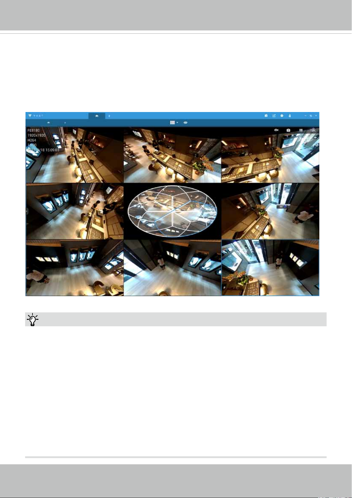
Using VIVOTEK Recording Software
VIVOTEK also provides a VAST recording software, allowing simultaneous monitoring and video
recording for multiple Network Cameras. Please install the recording software; then launch the
program to add the Network Camera to the Channel list. For detailed information about how to
use the recording software, please refer to the user’s manual of the software or download it from
http://www.vivotek.com.
Tips:
1. If you encounter problems with displaying live view or the onscreen plug-in control, you may try
to remove the plug-ins that might have been installed on your computer. Remove the following
folder: C:\Program Files (x86)\Camera Stream Controller\.
2. If you forget the root (administrator) password for the camera, you can restore the camera
defaults by pressing the reset button for longer than 5 seconds.
3. If DHCP is enabled in your network, and the camera cannot be accessed, run the Shepherd
utility to search the network. If the camera has been congured with xed IP that does not
comply with your local network, you may see its default IP 169.254.x.x. If you still cannot nd
the camera, you can restore the camera to its factory defaults.
4. If you change your network parameters, e.g., added a connection to a LAN card, re-start the
Shepherd utility.
30 - User's Manual
 Loading...