


Bullet
IB8373-EH
Network Camera
User’s Manual
3MP • 30m IR • IP67 • Smart IR • Smart Focus System
Day & Night • Weather-proof
Rev. 1.0

VIVOTEK
Table of Contents
Overview
Revision History ����������������������������������������������������������������������������������������������������������������������������������������������������� 4
Read Before Use ���������������������������������������������������������������������������������������������������������������������������������������������������� 5
Package Contents �������������������������������������������������������������������������������������������������������������������������������������������������� 5
Symbols and Statements in this Document ������������������������������������������������������������������������������������������������������������ 5
Physical Description ����������������������������������������������������������������������������������������������������������������������������������������������� 6
Installation
Hardware Installation ���������������������������������������������������������������������������������������������������������������������������������������������� 9
Network Deployment �������������������������������������������������������������������������������������������������������������������������������������������� 13
Software Installation ��������������������������������������������������������������������������������������������������������������������������������������������� 17
Ready to Use �������������������������������������������������������������������������������������������������������������������������������������������������������� 18
Accessing the Network Camera
Using Web Browsers �������������������������������������������������������������������������������������������������������������������������������������������� 21
Using RTSP Players ��������������������������������������������������������������������������������������������������������������������������������������������� 24
Using 3GPP-compatible Mobile Devices �������������������������������������������������������������������������������������������������������������� 25
Using VIVOTEK Recording Software ������������������������������������������������������������������������������������������������������������������� 26
Main Page
Client Settings
Conguration
System > General settings ����������������������������������������������������������������������������������������������������������������������������������� 38
System > Homepage layout �������������������������������������������������������������������������������������������������������������������������������� 39
System > Logs ����������������������������������������������������������������������������������������������������������������������������������������������������� 42
System > Parameters ������������������������������������������������������������������������������������������������������������������������������������������ 43
System > Maintenance ����������������������������������������������������������������������������������������������������������������������������������������� 44
Media > Image ��������������������������������������������������������������������������������������������������������������������������������������������������� 48
Media > Video ������������������������������������������������������������������������������������������������������������������������������������������������������ 58
Media > Video ������������������������������������������������������������������������������������������������������������������������������������������������������ 61
Media > Audio������������������������������������������������������������������������������������������������������������������������������������������������������� 68
Network > General settings ���������������������������������������������������������������������������������������������������������������������������������� 69
Network > Streaming protocols �������������������������������������������������������������������������������������������������������������������������� 77
Network > SNMP (Simple Network Management Protocol) ��������������������������������������������������������������������������������� 86
Security > User Account ��������������������������������������������������������������������������������������������������������������������������������������� 87
Security > HTTPS
Security > Access List ���������������������������������������������������������������������������������������������������������������������������������������� 93
PTZ > PTZ settings ���������������������������������������������������������������������������������������������������������������������������������������������� 98
Event > Event settings���������������������������������������������������������������������������������������������������������������������������������������� 102
Applications > Motion detection�������������������������������������������������������������������������������������������������������������������������� 117
Applications > DI and DO ����������������������������������������������������������������������������������������������������������������������������������� 120
Applications > Tampering detection ������������������������������������������������������������������������������������������������������������������� 120
Applications > Audio detection ������������������������������������������������������������������������������������������������������������������������� 121
Applications > VADP (VIVOTEK Application Development Platform) ���������������������������������������������������������������123
Recording > Recording settings ������������������������������������������������������������������������������������������������������������������������ 126
Local storage > SD card management ��������������������������������������������������������������������������������������������������������������� 131
Local storage > Content management ��������������������������������������������������������������������������������������������������������������� 132
��������������������������������������������������������������������������������������������������������������������������������������������������������������������
������������������������������������������������������������������������������������������������������������������������������������������������������������������
���������������������������������������������������������������������������������������������������������������������������
����������������������������������������������������������������������������������������������������������������������������������������������������������������
���������������������������������������������������������������������������������������������������������������������������������������������������������
�����������������������������������������������������������������������������������������������������������������������������������������������������������
(Hypertext Transfer Protocol over SSL)
���������������������������������������������������� 88
4
9
21
27
32
37
2 - User's Manual

VIVOTEK
Appendix
URL Commands for the Network Camera ������������������������������������������������������������������������������������������������ 135
Technical Specications ���������������������������������������������������������������������������������������������������������������������������214
Technology License Notice ����������������������������������������������������������������������������������������������������������������������� 215
Electromagnetic Compatibility (EMC) �������������������������������������������������������������������������������������������������������216
����������������������������������������������������������������������������������������������������������������������������������������������������
135
User's Manual - 3

VIVOTEK
Overview
VIVOTEK’s IB8373-EH network camera features a 3-Megapixel WDR CMOS sensor to cope with
challenging lighting conditions� The WDR Pro feature allows the camera to capture both the dark and
bright areas of an image and combine the differences to generate a highly realistic representation of the
original scene� This feature enables the camera to provide video quality very close to the capabilities of
the human eye� The IB8373-EH can be deployed widely in high contrast outdoor environments such as
parking areas and streets� The P-iris lens controls the iris with extreme precision; with its built-in stepper
motor, it maintains the iris opening at an optimal level at all times, resulting in superior image clarity and
depth of eld.
The IP67-rated housing is designed to help the camera body withstand rain and dust and ensures
smooth operation even under a multitude of harsh weather conditions� Additionally, the wide temperature
range further enhances the IB8373-EH’s performance and reliability in extremely cold environments�
Revision History
■ Rev. 1.0: Initial release.
4 - User's Manual
VIVOTEK
i
Read Before Use
The use of surveillance devices may be prohibited by law in your country� The Network Camera
is not only a high-performance web-ready camera but can also be part of a exible surveillance
system� It is the user’s responsibility to ensure that the operation of such devices is legal before
installing this unit for its intended use�
It is important to first verify that all contents received are complete according to the Package
Contents listed below� Take note of the warnings in the Quick Installation Guide before the Network
Camera is installed; then carefully read and follow the instructions in the Installation chapter to
avoid damage due to faulty assembly and installation� This also ensures the product is used
properly as intended�
The Network Camera is a network device and its use should be straightforward for those who
have basic networking knowledge� It is designed for various applications including video sharing,
general security/surveillance, etc� The Configuration chapter suggests ways to best utilize the
Network Camera and ensure proper operations� For creative and professional developers, the URL
Commands of the Network Camera section serves as a helpful reference to customizing existing
homepages or integrating with the current web server�
Package Contents
■ IB8373-EH with an RJ45 Cable
■
Sun Shield / Wrench / RJ45 Female-Female Coupler / Double-sided Tape / Screws
■ Wall Mount Bracket
■
Waterproof Connector for RJ45 Ethernet Enclosure
■ Waterproof Connector (for DI/DO and power wires)
■ Alignment Sticker / Desiccant Bag
■ Quick Installation Guide
■ Software CD
Symbols and Statements in this Document
INFORMATION: provides important messages or advices that might help prevent
inconvenient or problem situations�
NOTE: Notices provide guidance or advices that are related to the functional integrity of
the machine�
Tips: Tips are useful information that helps enhance or facilitae an installation, function,
or process�
WARNING! or IMPORTANT!: These statements indicate situations that can be
dangerous or hazardous to the machine or you�
Electrical Hazard: This statement appears when high voltage electrical hazards might
occur to an operator�
User's Manual - 5
VIVOTEK
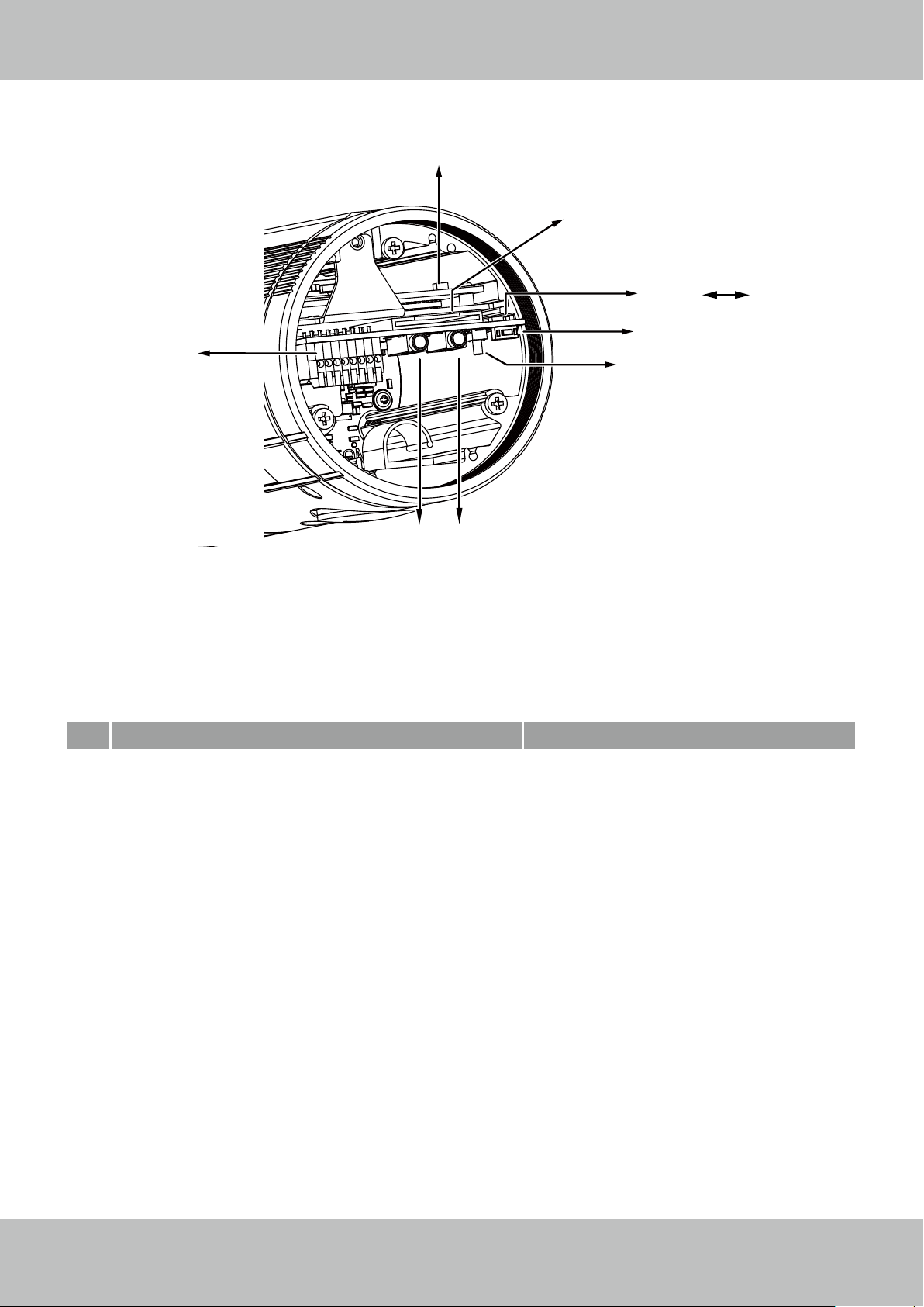
Physical Description
LED
SD/SDHC/SDXC Card Slot
NTSC-PAL switch
NTSCPAL
General I/O
Terminal Block
Audio in
AV out
Auto Focus
Reset Button
Status LED
Item LED status Description
Steady Red Power on and system booting
1
Red LED off Power off
2 Blinking Green every 1 sec� Network normal (heartbeat)
Steady Red and Green LED is off Network failed
Red blinking every 0�15 sec�, and Orange LED blinking
every 1 sec�
3
(Red on for 0�15 sec and off for 0�15 sec�); (Green on for 1
sec� and off for another� )
Blinking Orange every 0�15 sec� Both LEDs are on for 0�15
4
sec� and off for 0�15 sec�
6 - User's Manual
Upgrading firmware
Restoring default
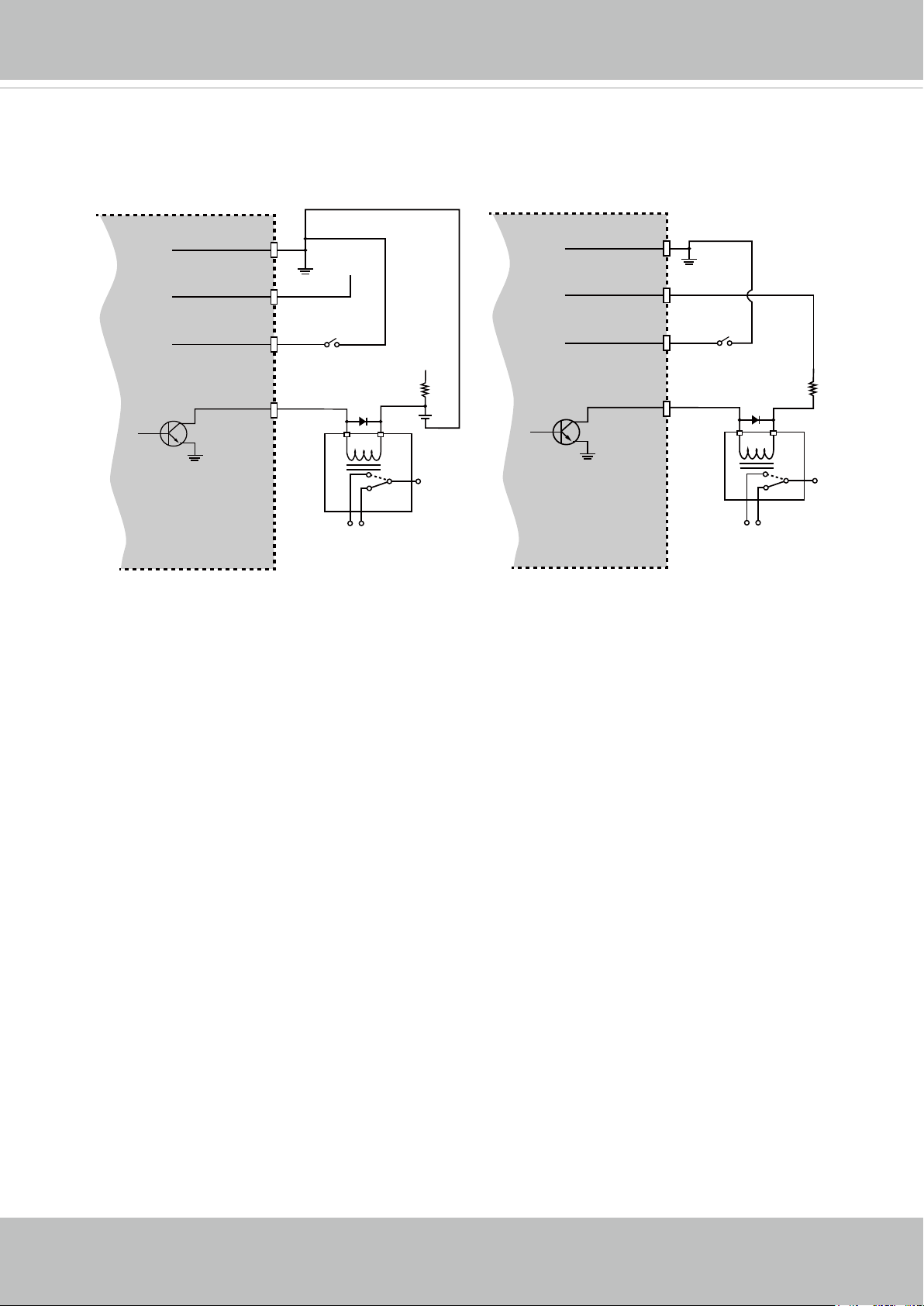
DI/DO Diagram
Please refer to the following illustration for the connection method�
VIVOTEK
Camera Power
BJT transistor
GND
Input
Output
VDC
Switch
Relay
+12
VDC
Max.
Camera Power
BJT transistor
GND
Input
Output
VDC
Switch
+12
VDC
Relay
User's Manual - 7
VIVOTEK
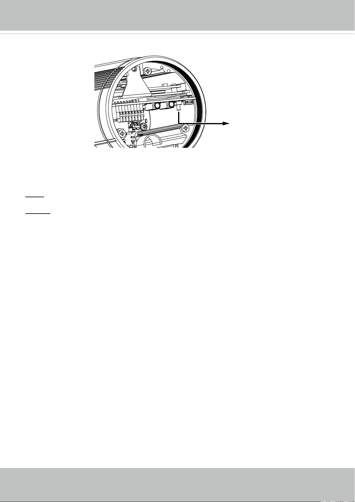
Hardware Reset
Reset Button
The reset button is used to reset the system or restore the factory default settings� Sometimes
resetting the system can return the camera to normal operation� If the system problems remain
after reset, restore the factory settings and install again�
Reset: Press and release the recessed reset button. Wait for the Network Camera to reboot.
Restore: Press and hold the recessed reset button until the status LED rapidly blinks. Note that
all settings will be restored to factory default� Upon successful restore, the status LED will blink
green and red during normal operation�
SD/SDHC/SDXC Card Capacity
This network camera is compliant with SD/SDHC/SDXC 16GB / 8GB / 32GB /64GB and other
preceding standard SD cards�
8 - User's Manual
VIVOTEK
Installation
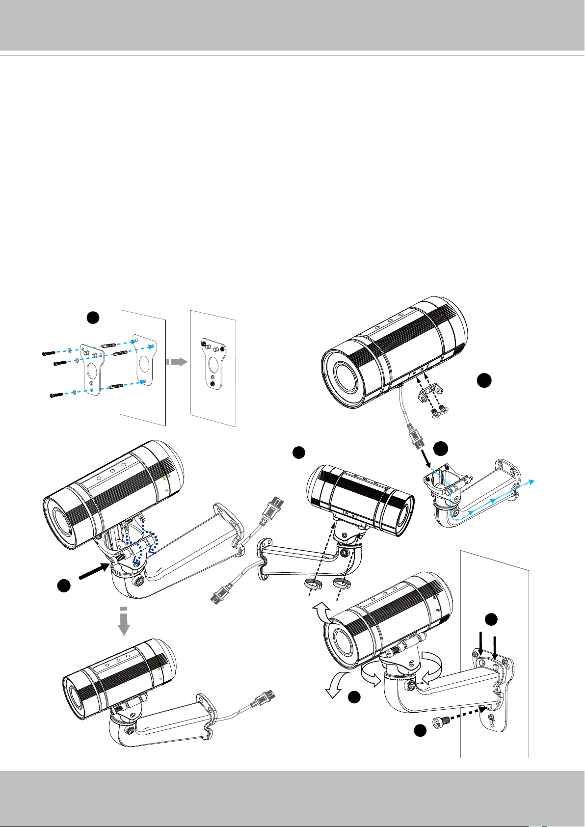
Hardware Installation
1� Attach the alignment sticker to the wall� Drill four holes into the wall� Then hammer the
supplied plastic anchors into the holes and secure the plate with supplied screws�
2� Fix the intersection bracket to the side of the Network Camera with two screws�
3. Feed the RJ45 cable through the front opening of the wall mount bracket. (If you want to use
external devices such as sensors and alarms, please refer to the assembling steps on the
next page�)
4� Push the spring mortise and hook the bracket onto the groove of the wall mount bracket�
5� Secure the two screws on the other side of the wall mount bracket�
6� Hang the wall mount bracket to the mounting plate�
7� Fix the wall mount bracket with the supplied screw�
8� Adjust the angle of the wall mount bracket to aim at the shooting area�
1
2
5
4
3
6
8
7
User's Manual - 9
VIVOTEK
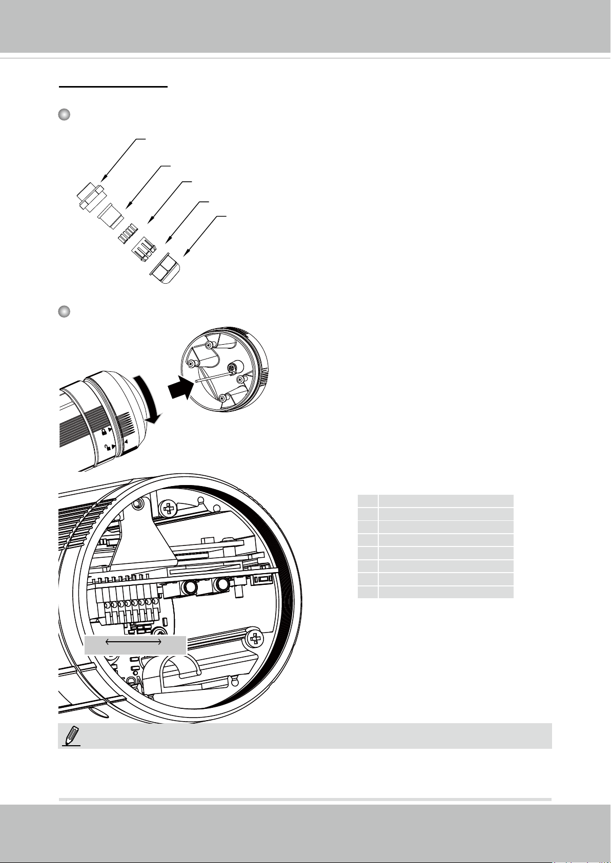
Waterproof Connector
Components of the Waterproof Connector
Screw Nut (A)
Seal (B)
Seals (C)
Housing (D)
Sealing Nut (E)
Pin Denitions
Open the rear cover by rotating to the
alignment mark, and pull the cover off the
canister�
Pin Denitions
1 DC 12V- IN
2 DC 12V+ IN
3 AC24V_2 IN
4 AC24V_1 IN
5 DI6 DI+
7 DO8 DO+ (12V)
8
Pin number
1
NOTE:
In addition to PoE (Power over Ethernet), you can also supply power to the camera using
pins #1~#4 from the terminal block, either using DC 12V or AC24V�
10 - User's Manual
VIVOTEK
9-2
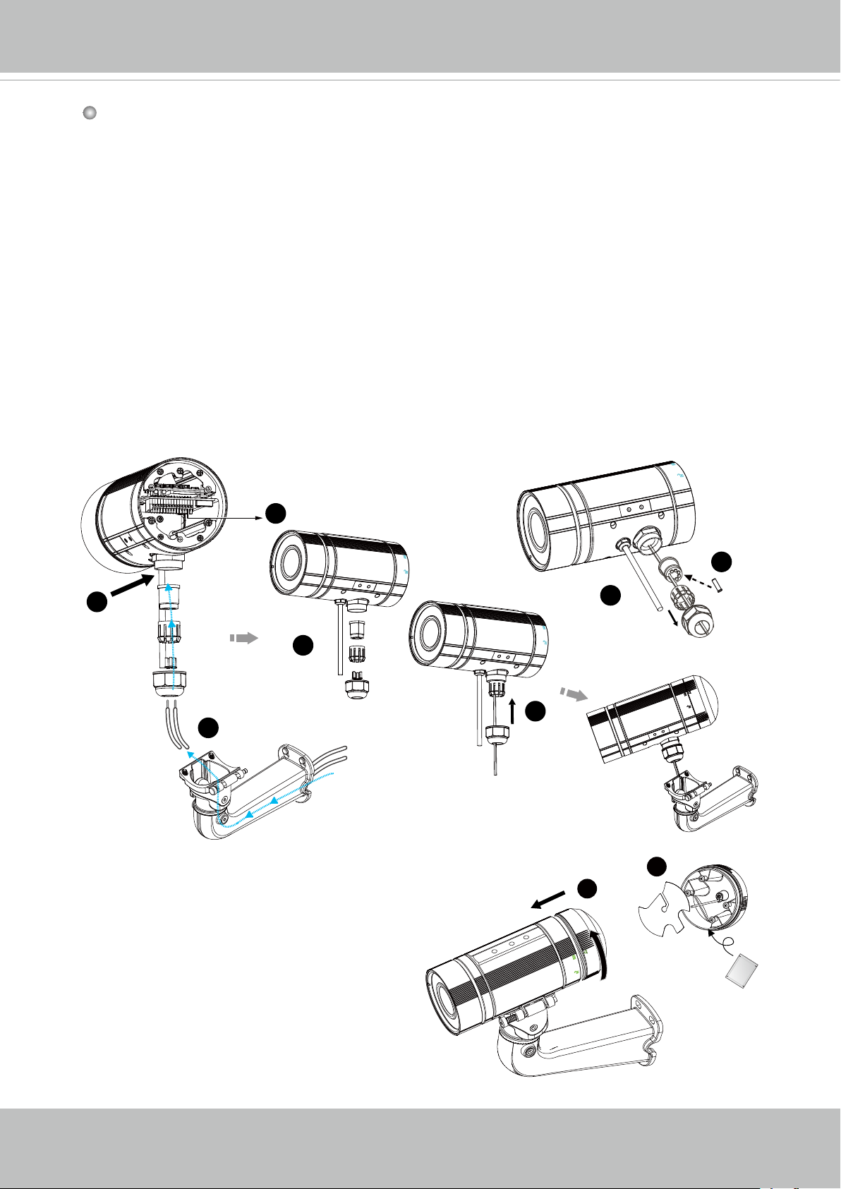
Assembling Steps
1� Disassemble the components of the waterproof connector into part (A) ~ (E) as shown
above�
2� Open the rear cover of the Network Camera�
3� Remove the rubber stopper from the bottom of the Network Camera and secure the
screw nut (A) tightly�
4� You may choose to use AC24V or DC12V inputs as power source, please feed the
power lines through the wall mount bracket and the waterproof connector (E --> D --> B -->
A) as illustrated below� Pass power lines through the rubber seal (B) and then connect
the power lines to the terminal block�
5� If you have external devices such as sensors and alarms, feed the cables through the
wall mount bracket and the waterproof connector (E --> D --> B --> A) as the illustration
shown below. Then refer to the pin denition to connect them to the general I/O terminal
block. Note: The recommended cable gauge is 2�0 ~ 2�8 mm�
6� Push the seal (B) into the housing (D)�
7� Insert the seals (C) into the empty holes on the seal (B) to avoid moisture�
8� Secure the sealing nut (E) tightly�
5
(A)
3
(B)
(D)
4
(E)
4
9� Open the aluminum foil vacuum bag
and take out the desiccant bag� Attach
the desiccant bag to the inner side of the
rear cover, to under the insulation pad,
and then tighten the rear cover� (Please
replace the desiccant bag with a new one
whenever you open the rear cover�)
(E)
7
6
(B)
(D)
8
9-1
9-2
(C)
User's Manual - 11

VIVOTEK
Cabling Assembly: RJ45 Cable Connector
RJ45 Cable Dimension (unit: mm)
Assembling Steps
Prepare an Ethernet
1
cable and strip part of the
sheath�
Recommended cable gauge:
O� D� 5�5~7
Insert the stripped Ether-
4
net cable through the sealing nut and the housing�
Insert the housing into
2
the screw nut�
Clamp the cable
5
with an RJ45 plug.
(C)
Components of the Waterproof
Connector
Sealing Nut (A)
Seal (B)
Screw Nut (C)
Housing (D)
Insert the seal into the
3
housing�
(D)
6
(B)
Push the RJ45 plug into
the housing, then secure
the sealing nut tightly�
Gasket (E)
(A)
7
Attach the gasket to the
front of the housing�
(E)
Connect the Ethernet cable to the RJ45 cable and secure
8
the connectors tightly�
12 - User's Manual
VIVOTEK
Network Deployment
Setting up the Network Camera over the Internet
This section explains how to congure the Network Camera to an Internet connection�
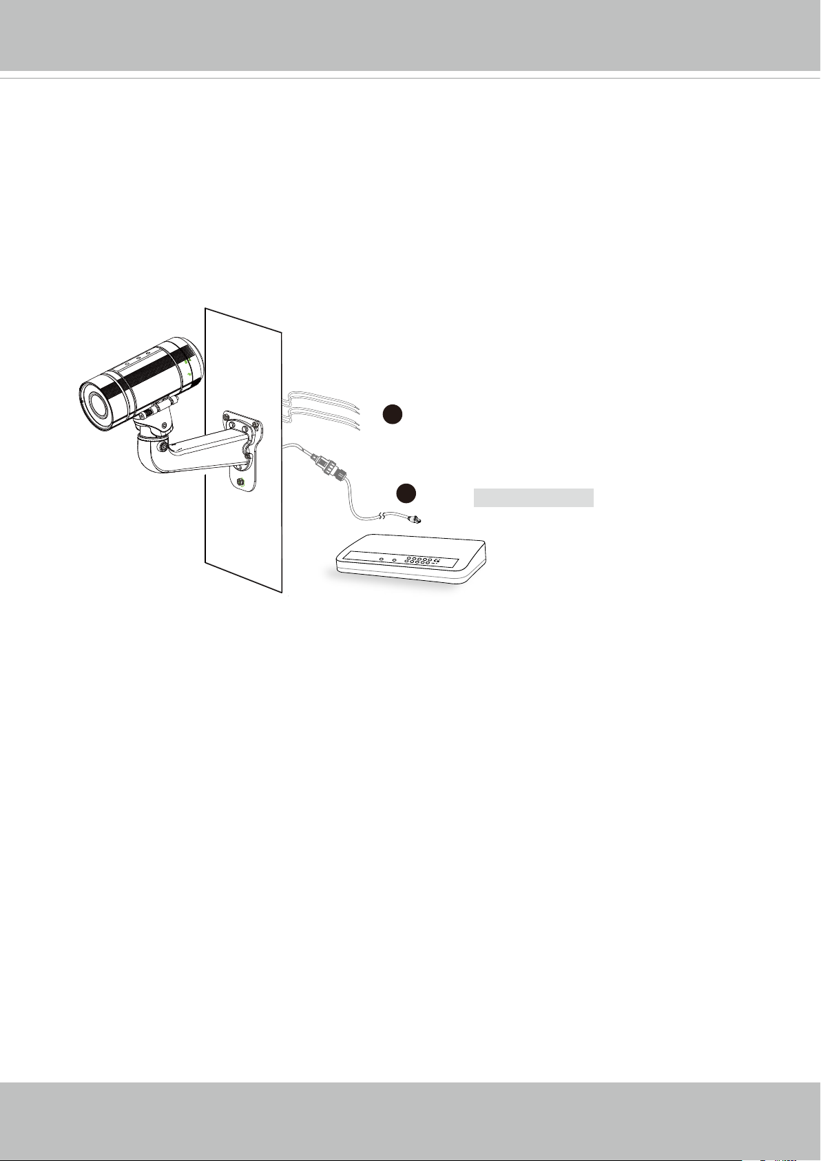
1� If you have external devices such as sensors and alarms, connect them to the general I/
O terminal block�
2� Connect the camera to a switch via Ethernet cable�
3� Connect either the DC 12V or AC 24V power wires from the Network Camera to a power
outlet�
3
2
POWER
COLLISION
LINK
RECEIVE
1
2
PARTITION
3
4
5
Ethernet Switch
There are several ways to set up the Network Camera over the Internet� The rst way is
to set up the Network Camera behind a router� The second way is to utilize a static IP� The
third way is using PPPoE�
User's Manual - 13
VIVOTEK
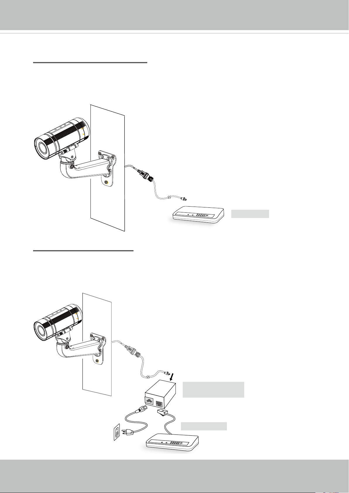
Set up the Network Camera through Power over Ethernet (PoE)
When using a PoE-enabled switch
The Network Camera is PoE-compliant, allowing transmission of power and data via a
single Ethernet cable� Follow the below illustration to connect the Network Camera to a
PoE-enabled switch via Ethernet cable�
power + data transmission
POWER
COLLISION
LINK
RECEIVE
1
2
PARTITION
3
4
5
PoE Switch
When using a non-PoE switch
If your switch/router does not support PoE, use a PoE power injector (optional) to connect
between the Network Camera and a non-PoE switch�
14 - User's Manual
PoE Power Injector
(optional)
Non-PoE Switch
POWER
COLLISION
LINK
RECEIVE
1
2
PARTITION
3
4
5
VIVOTEK
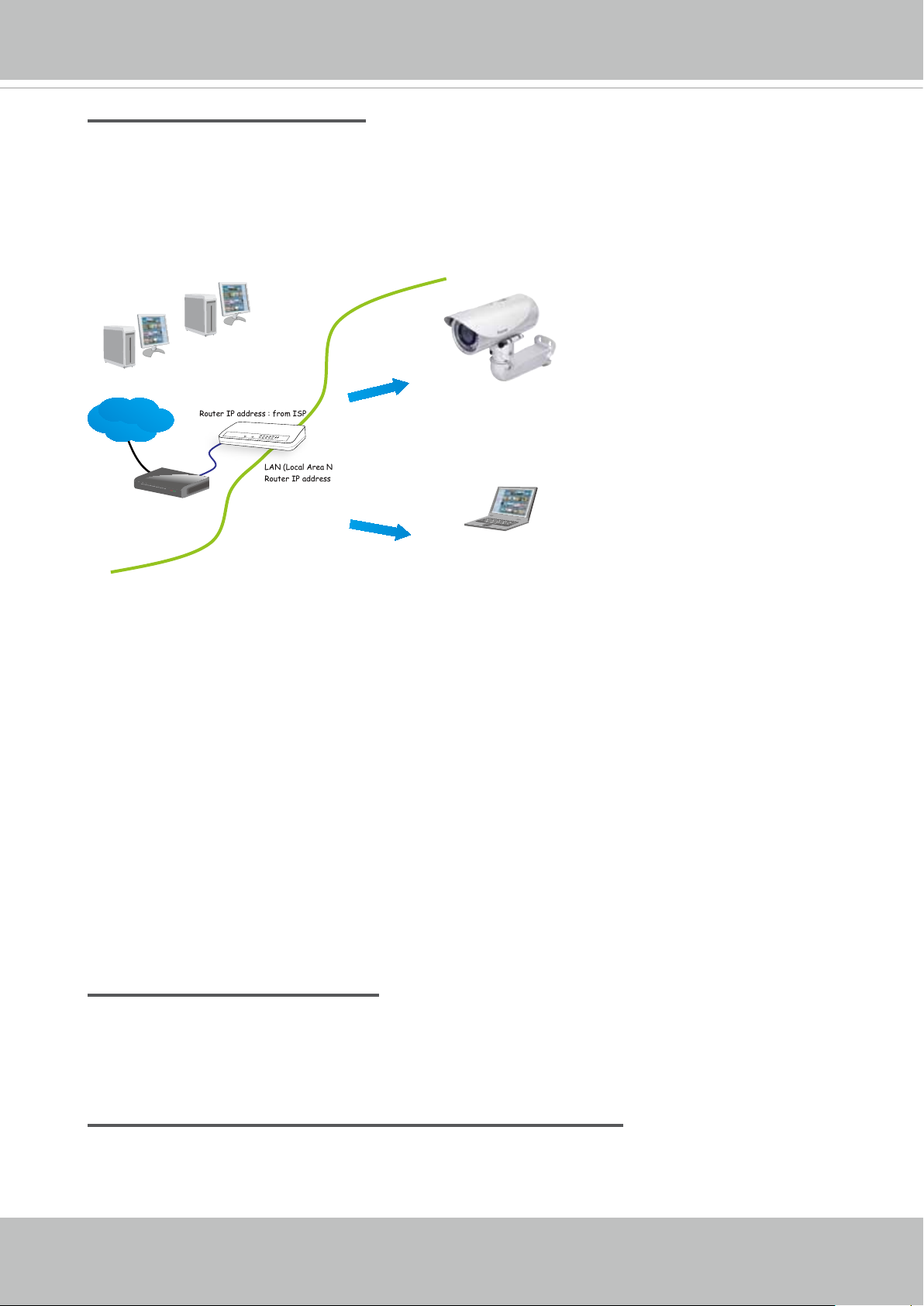
Internet connection via a router
Before setting up the Network Camera over the Internet, make sure you have a router and
follow the steps below�
1� Connect your Network Camera behind a router, the Internet environment is illustrated
below� Regarding how to obtain your IP address, please refer to Software Installation on
page 17 for details�
IP address : 192.168.0.3
Subnet mask : 255.255.255.0
Default router : 192.168.0.1
IP address : 192.168.0.2
Subnet mask : 255.255.255.0
Default router : 192.168.0.1
Internet
Cable or DSL Modem
WAN (Wide Area Network )
Router IP address : from ISP
LINK
POWER
COLLISION
RECEIVE
1
2
PARTITION
3
4
5
LAN (Local Area Network)
Router IP address : 192.168.0.1
2� In this case, if the Local Area Network (LAN) IP address of your Network Camera is
192�168�0�3, please forward the following ports for the Network Camera on the router�
■ HTTP port: default is 80
■ RTSP port: default is 554
■ RTP port for audio: default is 5558
■ RTCP port for audio: default is 5559
■ RTP port for video: default is 5556
■ RTCP port for video: default is 5557
If you have changed the port numbers on the Network page, please open the ports
accordingly on your router� For information on how to forward ports on the router, please
refer to your router’s documentation�
3� Find out the public IP address of your router provided by your ISP (Internet Service
Provider)� Use the public IP and the secondary HTTP port to access the Network
Camera from the Internet� Please refer to Network Type on page 69 for details�
Internet connection with static IP
Choose this connection type if you are required to use a static IP for the Network Camera�
Please refer to LAN settings on page 69 for details�
Internet connection via PPPoE (Point-to-Point over Ethernet)
Choose this connection type if you are connected to the Internet via a DSL Line� Please
refer to PPPoE on page 65 for details�
User's Manual - 15
VIVOTEK
For example, your router and IP settings may look like this:
Device IP Address: internal
port
IP Address: External Port (Mapped port on
the router)
Public IP of router 122�146�57�120
LAN IP of router 192�168�2�1
Camera 1 192.168.2.10:80 122.146.57.120:8000
Camera 2 192.168.2.11:80 122.146.57.120:8001
��� ��� ���
Congure the router, virtual server or rewall, so that the router can forward any data
coming into a precongured port number to a network camera on the private network, and
allow data from the camera to be transmitted to the outside of the network over the same
path�
From Forward to
122.146.57.120:8000 192.168.2.10:80
122.146.57.120:8001 192.168.2.11:80
��� ���
When properly congured, you can access a camera behind the router using the HTTP
request as follows: http://122.146.57.120:8000
If you change the port numbers on the Network conguration page, please open the ports
accordingly on your router� For example, you can open a management session with your
router to congure access through the router to the camera within your local network.
Please consult your network administrator for router conguration if you have troubles with
the conguration.
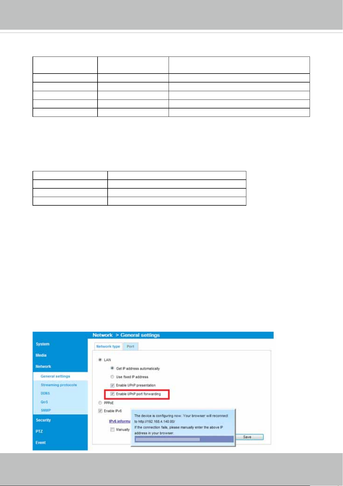
For more information with network conguration options (such as that of streaming ports),
please refer to Conguration > Network Settings. VIVOTEK also provides the automatic
port forwarding feature as an NAT traversal function with the precondition that your router
must support the UPnP port forwarding feature�
16 - User's Manual
VIVOTEK
Software Installation
Installation Wizard 2 (IW2), free-bundled software included on the product CD, helps you set up
your Network Camera on the LAN�
IW
1� Install IW2 under the Software Utility directory from the software CD�
Double-click the IW2 shortcut on your desktop to launch the program�
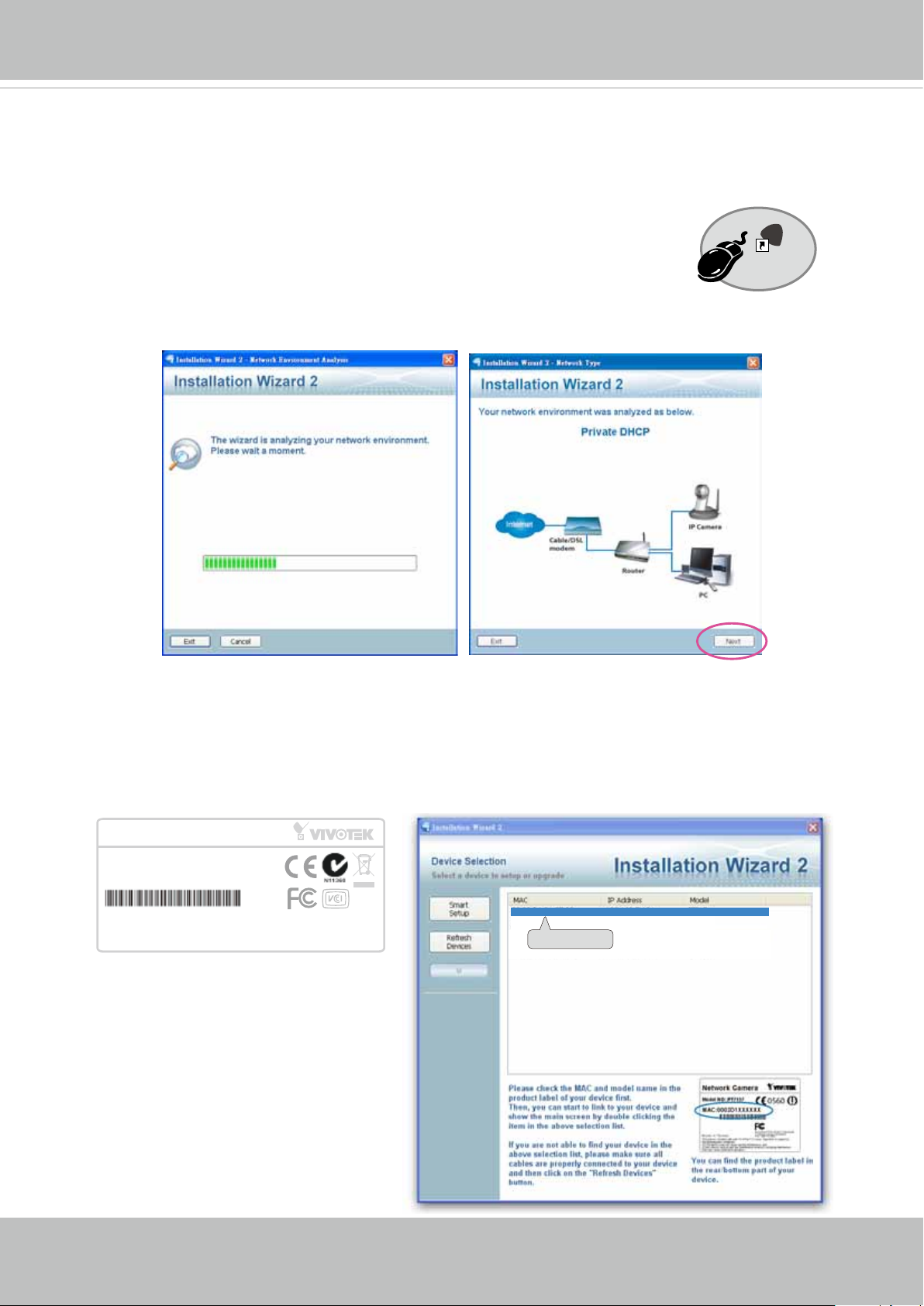
2� The program will conduct an analysis of your network environment�
After your network environment is analyzed, please click Next to continue the program�
2
Installation
Wizard 2
3� The program will search for all VIVOTEK network devices on the same LAN�
4� After a brief search, the installer window will prompt� Click on the MAC and model name
that matches the one printed on the product label� You can then double-click on the address to
open a management session with the Network Camera�
Network Camera
Model No: IB8373-EH
MAC:0002D1730202
This device complies with part 15 of the FCC rules. Operation is subject to the following two conditions:
(1)This device may not cause harmful interference, and
(2) this device must accept any interference received, including interference that may cause undesired operation.
Pat. 6,930,709
R o HS
Made in Taiwan
00-02-D1-73-02-02 192.168.5.151 IB8373-EH
0002D1730202
User's Manual - 17
VIVOTEK
Ready to Use
1� A browser session with the Network Camera should prompt as shown below�
2� You should be able to see live video from your camera� You may also install the 32-channel
recording software from the software CD in a deployment consisting of multiple cameras� For
its installation details, please refer to its related documents�
18 - User's Manual
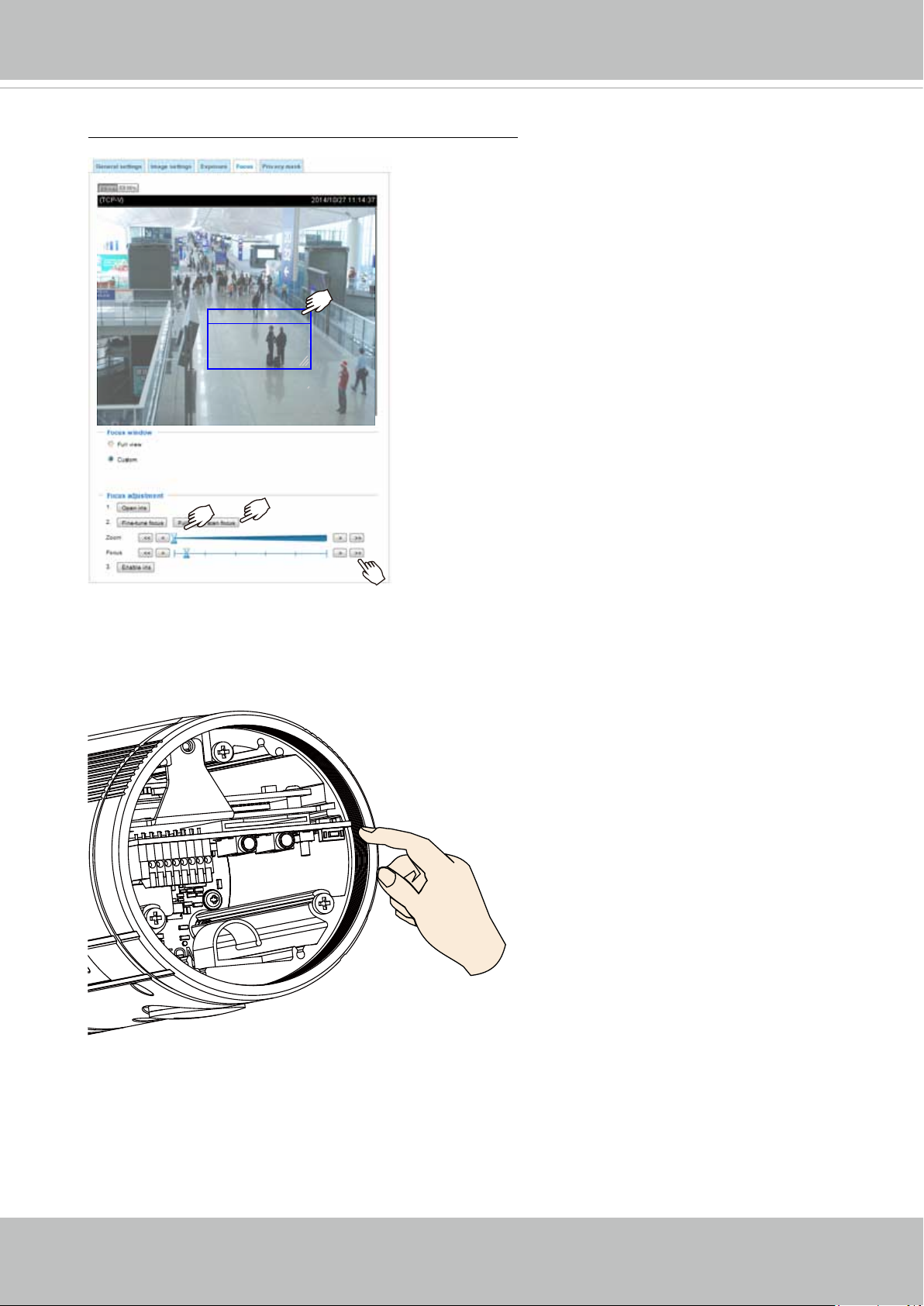
To adjust the zoom factor and focus range
1� The camera comes with a motorized vari-
focal lens module� With a web console,
you can enter the Configuration > Media
> Image > Focus page to tune the image
zoom and focus�
2� On this page, you can pull the Zoom and
Focus window
Focus pointers, set up a Focus window,
and use the Perform auto focus button to
automatically obtain an optimal focus result�
You may also manually fine-tune zoom and
focus using the various functional buttons�
Please refer to page 55, Media > Image >
Focus for more information�
VIVOTEK
3� You may also push the Auto Focus & Zoom
buttons on the camera to obtain the same
results especially when you are using camera
tester for onsite adjustment�
User's Manual - 19
VIVOTEK
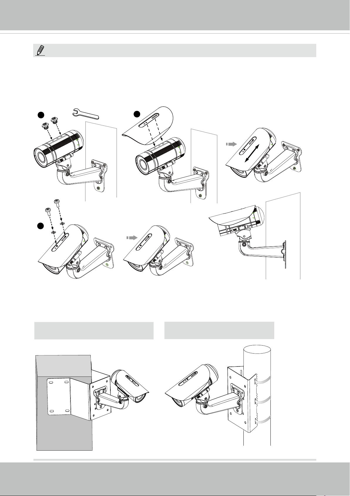
NOTE:
If you want to use the supplied sun shield for outdoor environments, please follow the
steps below to install:
1� Tighten the supplied two hex couplers�
2� Attach the supplied sun shield to the Network Camera and slide it to the desired position�
3� Fix the sun shield with the supplied two screws�
1
3
2
Accessories
VIVOTEK also provides other accessories for versatile applications as the following
illustrations. Please visit VIVOTEK's ofcial website for more purchase information.
Corner Mount Bracket
Pole Mount Bracket
20 - User's Manual
VIVOTEK
Accessing the Network Camera
This chapter explains how to access the Network Camera through web browsers, RTSP players,
3GPP-compatible mobile devices, and VIVOTEK recording software�
Using Web Browsers
Use Installation Wizard 2 (IW2) to access the Network Cameras on LAN�
If your network environment is not a LAN, follow these steps to access the Netwotk Camera:
1� Launch your web browser (e�g�, Microsoft
2. Enter the IP address of the Network Camera in the address eld. Press Enter�
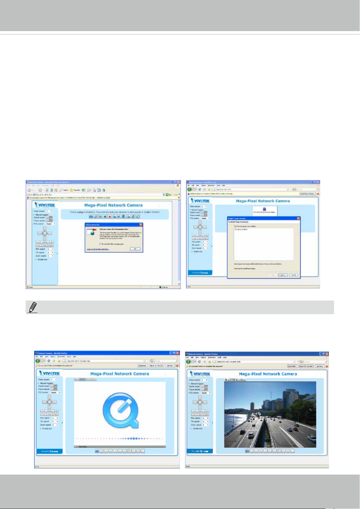
3� The live video will be displayed in your web browser�
4. If it is the rst time installing the VIVOTEK network camera, an information bar will prompt as
shown below� Follow the instructions to install the required plug-in on your computer�
®
Internet Explorer or Mozilla Firefox)�
NOTE:
NOTE
► For Mozilla Firefox users, your browser will use Quick Time to stream the live video. If you
don’t have Quick Time on your computer, please download it first, then launch the web
browser�
User's Manual - 21
VIVOTEK
► By default, the Network Camera is not password-protected. To prevent unauthorized access,
it is highly recommended to set a password for the Network Camera�
For more information about how to enable password protection, please refer to Security on
page 87�
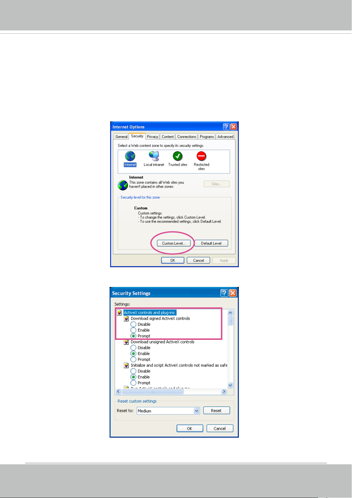
► If you see a dialog box indicating that your security settings prohibit running ActiveX
®
Controls, please enable the ActiveX
Controls for your browser�
®
1� Choose Tools > Internet Options > Security > Custom Level�
2� Look for Download signed ActiveX
®
controls; select Enable or Prompt� Click OK�
3� Refresh your web browser, then install the ActiveX
complete installation�
®
control� Follow the instructions to
22 - User's Manual

IMPORTANT:
Currently the Network Camera utilizes a 32-bit ActiveX plugin. You CAN NOT open a
•
management/view session with the camera using a 64-bit IE browser.
If you encounter this problem, try execute the Iexplore.exe program from C:\Windows\
•
SysWOW64. A 32-bit version of IE browser will be installed.
On Windows 7, the 32-bit explorer browser can be accessed from here: C:\Program
•
Files (x86)\Internet Explorer\iexplore.exe
If you experience compatibility issues between the plug-in control, you may try to
•
uninstall the Camera Stream Controller located in: C:/Program Files (x86)/Camera
Stream Controller.
VIVOTEK
Tips:
1� The onscreen Java control can malfunction under the following situations: A PC con-
nects to different cameras that are using the same IP address (or the same camera
running different rmware versions). Removing your browser cookies will solve this
problem�
2� If you encounter problems with displaying the conguration menus or UI items, try dis-
able the Compatibility View on IE8 or IE9�
You may also press the F12 key to open the developer tools utility, and then change the
Browser Mode to the genuine IE8 or IE9 mode�
User's Manual - 23
VIVOTEK
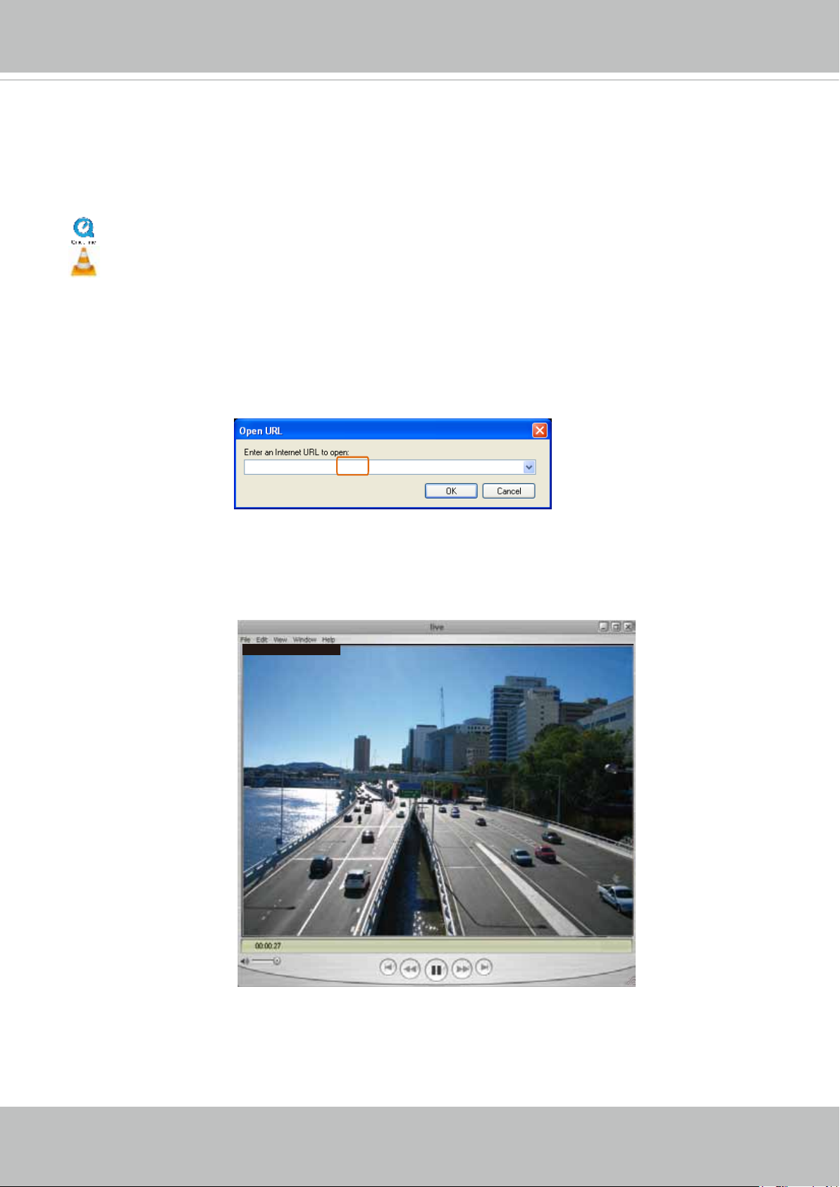
Using RTSP Players
To view the streaming media using RTSP players, you can use one of the following players that
support RTSP streaming�
Quick Time Player
VLC media player
mpegable Player
1� Launch the RTSP player�
2� Choose File > Open URL� A URL dialog box will pop up�
pvPlayer
3. The address format is rtsp://<ip address>:<rtsp port>/<RTSP streaming access name for
stream1 or stream2>
As most ISPs and players only allow RTSP streaming through port number 554, please set the
RTSP port to 554� For more information, please refer to RTSP Streaming on page 78�
For example:
rtsp://192.168.5.151:554/live.sdp
4� The live video will be displayed in your player�
For more information on how to configure the RTSP access name, please refer to RTSP
Streaming on page 78 for details�
Video 16:38:01 2012/01/25
24 - User's Manual
VIVOTEK
Using 3GPP-compatible Mobile Devices
To view the streaming media through 3GPP-compatible mobile devices, make sure the Network
Camera can be accessed over the Internet� For more information on how to set up the Network
Camera over the Internet, please refer to Setup the Network Camera over the Internet on page
15�
To utilize this feature, please check the following settings on your Network Camera:
1� Because most players on 3GPP mobile phones do not support RTSP authentication, make
sure the authentication mode of RTSP streaming is set to disable�
For more information, please refer to RTSP Streaming on page 78�
2� As the the bandwidth on 3G networks is limited, you will not be able to use a large video size�
Please set the video and audio streaming parameters as listed below�
For more information, please refer to Stream settings on page 59�
Video Mode MPEG-4
Frame size 176 x 144
Maximum frame rate 5 fps
Intra frame period 1S
Video quality (Constant bit rate) 40kbps
Audio type (GSM-AMR) 12.2kbps
3� As most ISPs and players only allow RTSP streaming through port number 554, please set
the RTSP port to 554� For more information, please refer to RTSP Streaming on page 78�
4� Launch the player on the 3GPP-compatible mobile devices�
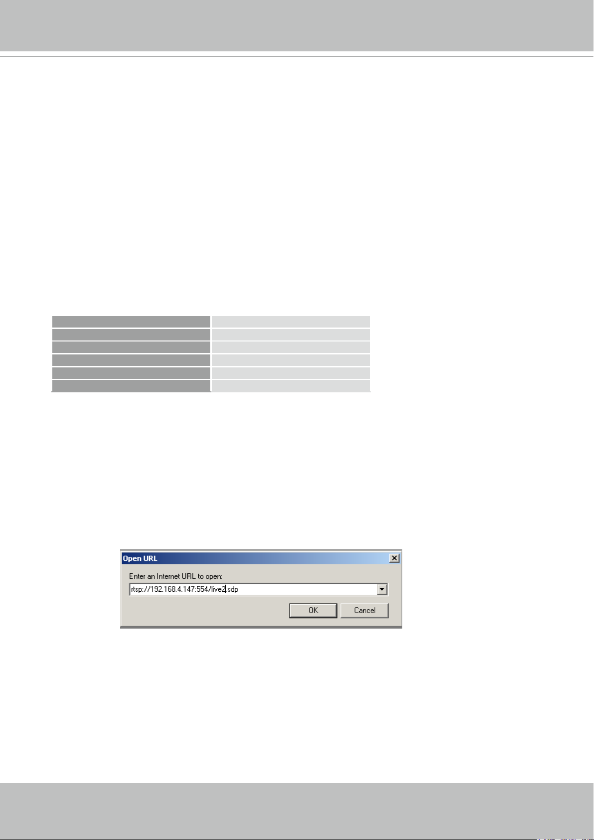
5� Type the following URL commands into the player�
The address format is rtsp://<public ip address of your camera>:<rtsp port>/<RTSP streaming
access name for stream # with small frame size and frame rate>�
For example:
You can configure Stream #2 into the suggested stream settings as listed above for live
viewing on a mobile device�
User's Manual - 25
VIVOTEK
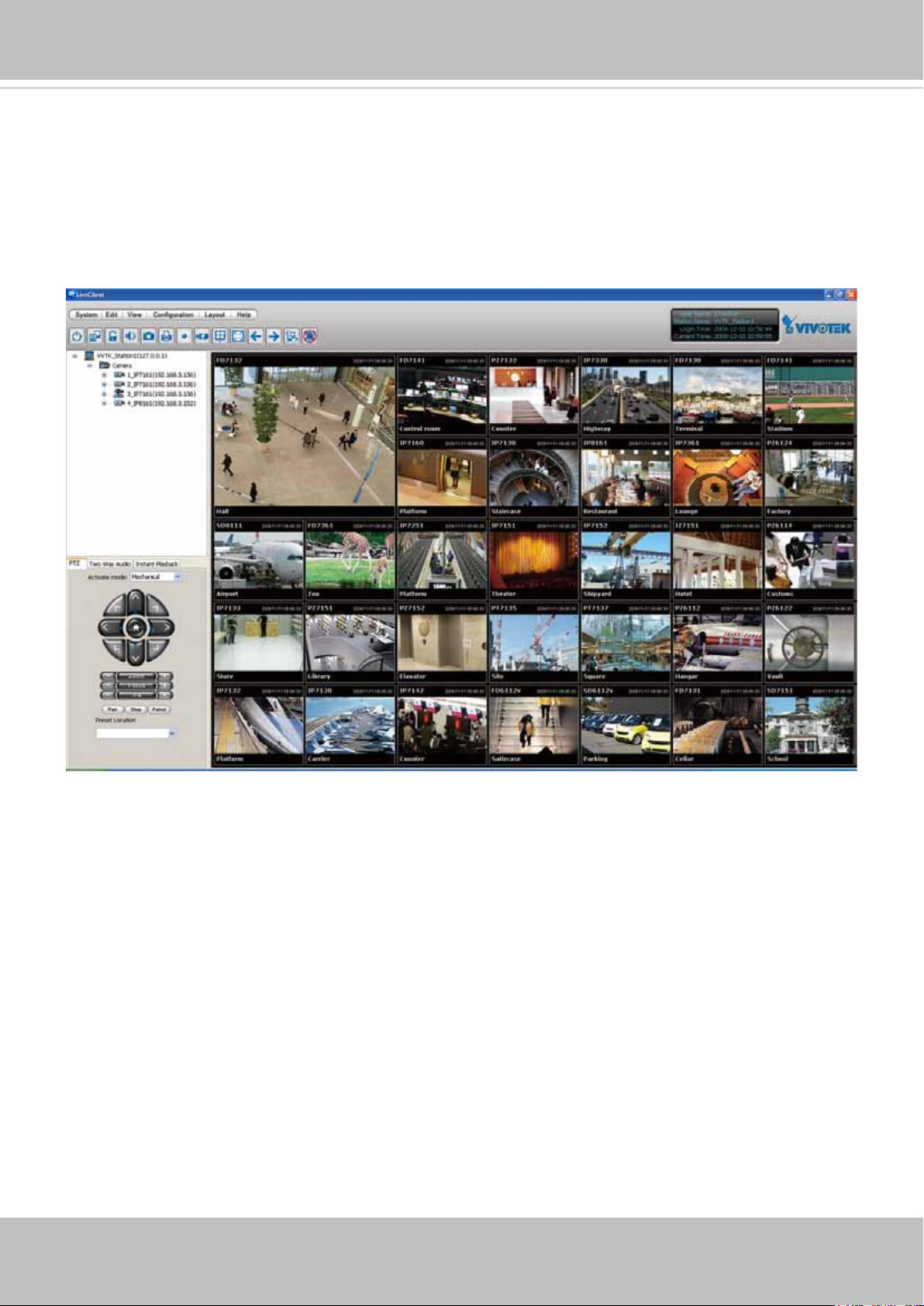
Using VIVOTEK Recording Software
The product software CD also contains an ST7501 recording software, allowing simultaneous
monitoring and video recording for multiple Network Cameras� Please install the recording
software; then launch the program to add the Network Camera to the Channel list� For detailed
information about how to use the recording software, please refer to the user’s manual of the
software or download it from http://www.vivotek.com�
26 - User's Manual
VIVOTEK
VIVOTEK INC.
Logo
Live View Window
Camera Control
Area
Configuration
Area
Host Name
Resize Buttons
Hide Button
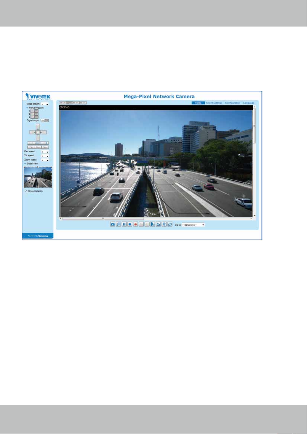
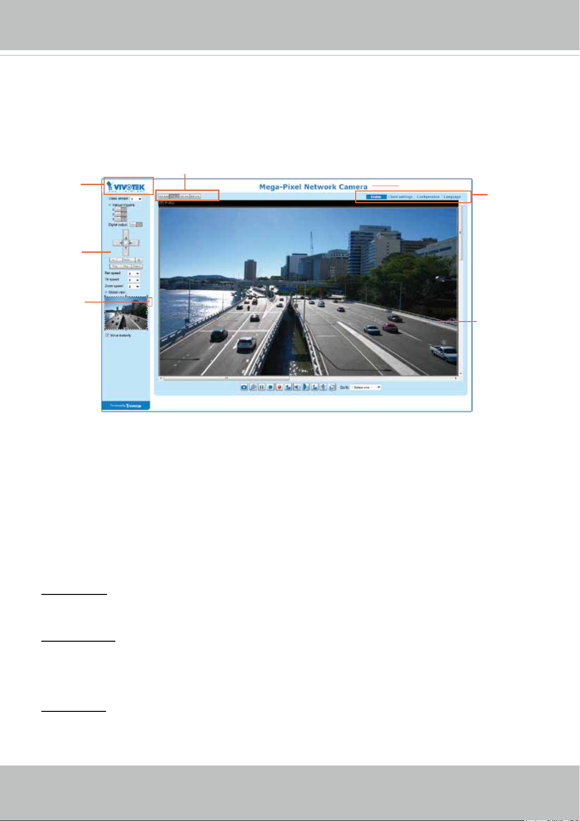
Main Page
This chapter explains the layout of the main page. It is composed of the following sections:
VIVOTEK INC� Logo, Host Name, Camera Control Area, Configuration Area, Menu, and Live
Video Window�
VIVOTEK INC. Logo
Click this logo to visit the VIVOTEK website�
Host Name
The host name can be customized to t your needs. For more information, please refer to System on page 38.
Camera Control Area
Video Stream: This Network Camera supports multiple streams (stream 1 ~ 4) simultaneously. You can
select either one for live viewing� For more information about multiple streams, please refer to page 59
for detailed information�
Manual Trigger: Click to enable/disable an event trigger manually. Please configure an event setting
on Application page before enable this function. A total of 3 event settings can be congured. For more
information about event setting, please refer to page 101� If you want to hide this item on the homepage,
please go to Conguration> System > Homepage Layout > General settings > Customized button
to deselect “show manual trigger button”�
Digital Output: Click to turn the digital output device on or off.
User's Manual - 27
VIVOTEK
H.264 Protocol and Media Options
Conguration Area
Client Settings: Click this button to access the client setting page. For more information, please refer to
Client Settings on page 32�
Conguration: Click this button to access the conguration page of the Network Camera. It is suggested
that a password be applied to the Network Camera so that only the administrator can configure the
Network Camera. For more information, please refer to Conguration on page 37.
Language: Click this button to choose a language for the user interface. Language options are available
in: English, Deutsch, Español, Français, Italiano,
日本語
, Português,
簡体中文
, and
繁體中文
� Please
note that you can also change a language on the Conguration page; please refer to page 37.
Hide Button
You can click the hide button to hide the control panel or display the control panel�
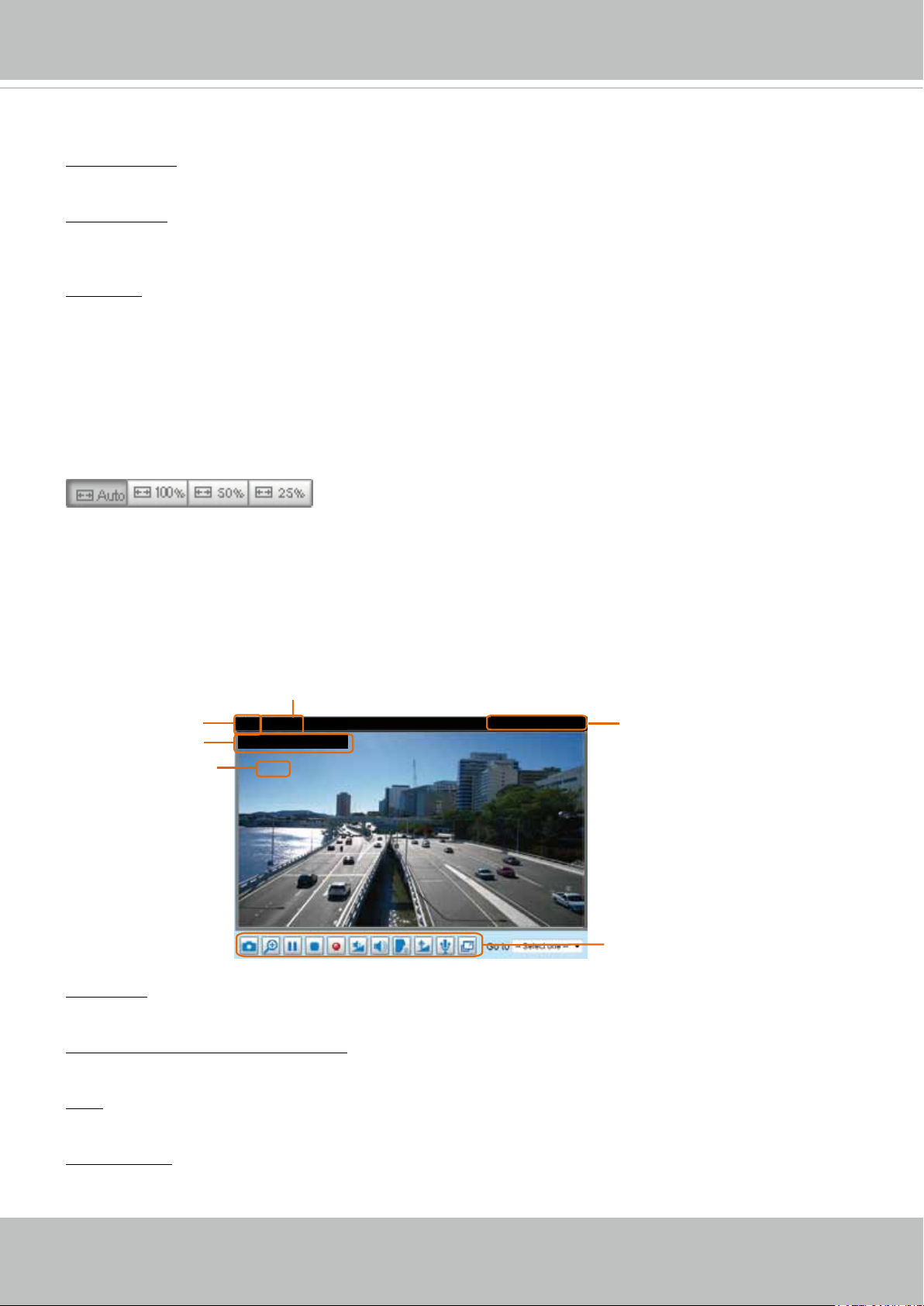
Resize Buttons
:
Click the Auto button, the video cell will resize automatically to t the monitor.
Click 100% is to display the original homepage size�
Click 50% is to resize the homepage to 50% of its original size�
Click 25% is to resize the homepage to 25% of its original size�
Live Video Window
■ The following window is displayed when the video mode is set to H.264:
Video Title
Title and Time
Zoom Indicator
Video (TPC-AV)
Video 17:08:56 2014/06/25
x4.0
Video Title: The video title can be congured. For more information, please refer to Video Settings on
page 48�
H�264 Protocol and Media Options: The transmission protocol and media options for H.264 video
streaming. For further conguration, please refer to Client Settings on page 32.
2014/06/25 17:08:56
Time
Video and Audio Control Buttons
Time: Display the current time. For further conguration, please refer to Media > Image > Genral settings
on page 48�
Title and Time: The video title and time can be stamped on the streaming video. For further conguration,
please refer to Media > Image > General settings on page 51�
28 - User's Manual
VIVOTEK
PTZ Panel: This Network Camera supports “digital“ (e-PTZ) pan/tilt/zoom control, which allows roaming
a smaller view frame within a large view frame� Please refer to PTZ settiings on page 98 for detailed
information�
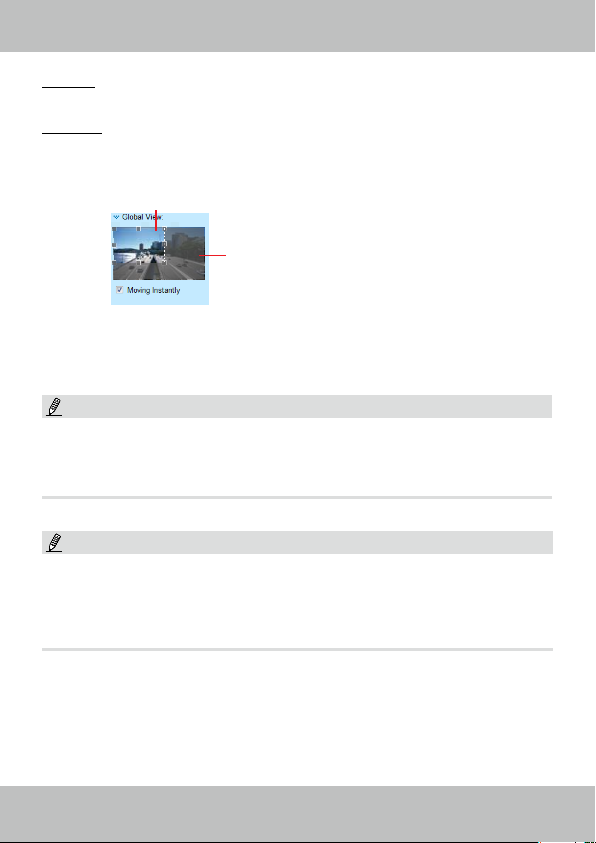
Global View: Click on this item to display the Global View window� The Global View window contains a
full view image (the largest frame size of the captured video) and a oating frame (the viewing region of
the current video stream). The oating frame allows users to control the e-PTZ function (Electronic Pan/
Tilt/Zoom)� For more information about e-PTZ operation, please refer to E-PTZ Operation on page 98�
For more information about how to set up the viewing region of the current video stream, please refer to
page 98�
The viewing region of
the current video
stream
The largest frame size
NOTE:
1� For a megapixel camera, it is recommended to use monitors of the 24" size or larger, and
are capable of 1600x1200 or better resolutions�
2� The video input is "muted" by default� To receive audio into from external microphone, you
need to enable the audio input from Media > Audio� Refer to page 68 for more information�
NOTE:
Quick Time player only supports playback of H.264 stream, and not the MJPEG stream. In terms of audio
codec, Quick Time only supports AAC� Since this camera supports G�711 codec, audio is not available
on Quick Time�
VLC player supports H.264/MPEG-4/MJPEG, and all audio codecs supported by VIVOTEK’s cameras.
User's Manual - 29
VIVOTEK
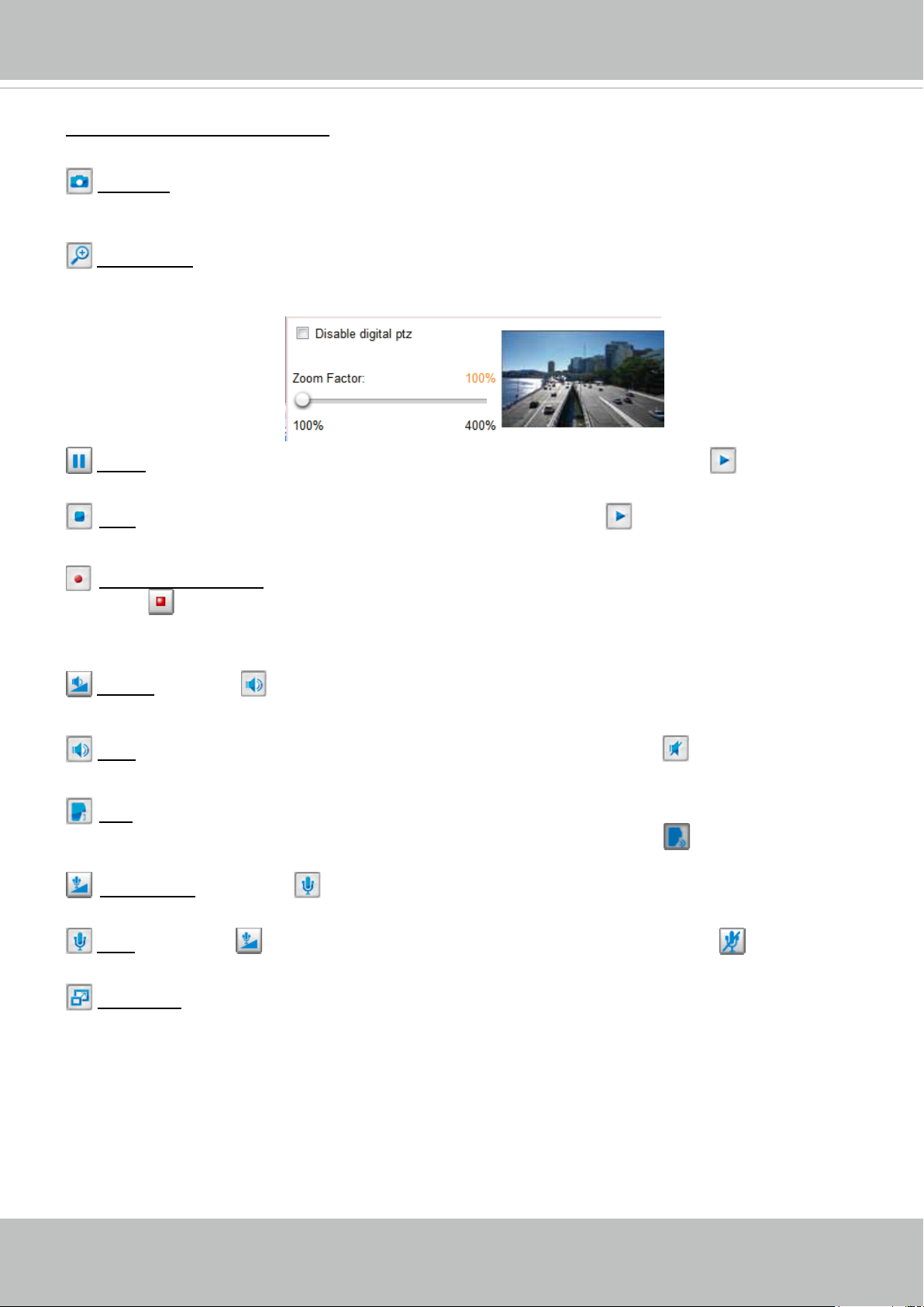
Video and Audio Control Buttons: Depending on the Network Camera model and Network Camera
conguration, some buttons may not be available.
Snapshot: Click this button to capture and save still images. The captured images will be displayed
in a pop-up window� Right-click the image and choose Save Picture As to save it in JPEG (*.jpg) or BMP
(*.bmp) format.
Digital Zoom: Click and uncheck “Disable digital zoom” to enable the zoom operation. The navigation
screen indicates the part of the image being magnied. To control the zoom level, drag the slider bar. To
move to a different area you want to magnify, drag the navigation screen�
Pause: Pause the transmission of the streaming media. The button becomes the Resume button
after clicking the Pause button�
Stop: Stop the transmission of the streaming media. Click the Resume button to continue
transmission�
Start MP4 Recording: Click this button to record video clips in MP4 file format to your computer.
Press the
Stop MP4 Recording button to end recording� When you exit the web browser, video
recording stops accordingly. To specify the storage destination and le name, please refer to MP4 Saving
Options on page 33 for details�
Volume: When the Mute function is not activated, move the slider bar to adjust the volume on the
local computer�
Mute: Turn off the volume on the local computer� The button becomes the Audio On button after
clicking the Mute button�
Talk: Click this button to talk to people around the Network Camera. Audio will project from
the external speaker connected to the Network Camera� Click this button
again to end talking
transmission�
Mic Volume: When the Mute function is not activated, move the slider bar to adjust the
microphone volume on the local computer�
Mute: Turn off the Mic volume on the local computer� The button becomes the Mic On button
after clicking the Mute button�
Full Screen: Click this button to switch to full screen mode. Press the “Esc” key to switch back to normal
mode�
30 - User's Manual
 Loading...