

Page 1
VIVOTEK - A Leading Provider of Multimedia Communication Solutions
Rev. 1.9
User's Manual - 1
Page 2

VIVOTEK - A Leading Provider of Multimedia Communication Solutions
Table of Contents
Revision History ..................................................................................................................................................... 8
Getting Started .......................................................................................................................................................... 10
Introducing VAST .................................................................................................................................................. 10
New Features ................................................................................................................................................ 10
Key Features ................................................................................................................................................. 10
VAST Server and Client Components .................................................................................................................. 11
Usage Scenario .................................................................................................................................................... 11
Technical Specications .......................................................................................................................................12
VAST Server Functionality .................................................................................................................................... 13
VAST LiveClient Functionality .............................................................................................................................. 14
VAST Playback Functionality ................................................................................................................................ 15
Minimum System Requirements .......................................................................................................................... 16
VAST Installation ....................................................................................................................................................... 18
Installing the VAST Software ................................................................................................................................ 18
VAST Server .............................................................................................................................................................. 20
Activating the VAST Server .................................................................................................................................. 20
How to Congure the Server ................................................................................................................................ 20
How to Stop/Reboot the Server ............................................................................................................................ 20
VAST LiveClient Conguration .................................................................................................................................. 21
Activating the VAST LiveClient and Logging in to a VAST Server ........................................................................ 21
VAST LiveClient User Interface ............................................................................................................................ 22
Menu Bar ....................................................................................................................................................... 22
Status Panel .................................................................................................................................................. 22
Help Panel ............................................................................................................................................................ 23
Quick Access Bar .......................................................................................................................................... 24
Live Video Monitoring Window ...................................................................................................................... 24
Hierarchical Management Tree ..................................................................................................................... 25
Camera Control Panel ................................................................................................................................... 26
Pan/Tilt/Zoom (PTZ) Control Panel ........................................................................................................ 26
Two Way Audio Control Panel ................................................................................................................ 28
Language Selection ............................................................................................................................... 28
Alarm Window ............................................................................................................................................... 29
Alarm Filter ............................................................................................................................................. 30
Instant Playback ............................................................................................................................................ 32
Instant Replay ............................................................................................................................................... 33
Audio Control ................................................................................................................................................ 34
How to Manage Devices ...................................................................................................................................... 35
Insert Cameras .............................................................................................................................................. 35
Seamless Recording ..................................................................................................................................... 39
Enable SVC .................................................................................................................................................. 41
2 - User's Manual
Page 3

VIVOTEK - A Leading Provider of Multimedia Communication Solutions
Insert NVR (Network Video Recorder) .......................................................................................................... 44
Insert a Video Server ..................................................................................................................................... 46
Update Devices ............................................................................................................................................. 48
Delete Devices from the VAST Server .......................................................................................................... 49
Batch Insert Devices ..................................................................................................................................... 50
Camera Conguration ................................................................................................................................... 55
View Live Videos ........................................................................................................................................... 60
Dual / Multiple Streams .......................................................................................................................... 60
Fisheye Display Modes .......................................................................................................................... 60
Refresh ................................................................................................................................................... 65
Streaming Server ................................................................................................................................... 65
Get Public IP .......................................................................................................................................... 65
Camera Settings .................................................................................................................................... 66
Open Recording Folder .......................................................................................................................... 66
Remove Live Video from the Video Monitoring Window ............................................................................... 67
How to Change the VAST LiveClient Layout ........................................................................................................ 68
Changing the Layout of the Live Video Monitoring Window .......................................................................... 68
Switch Video Channels .......................................................................................................................... 68
Congure Layout Mode .......................................................................................................................... 69
Congure Layout Mode .......................................................................................................................... 69
Rotating Video Pages ............................................................................................................................ 71
Edit Layout ............................................................................................................................................. 71
Maximize/Minimize the Live Video Monitoring Window ................................................................................. 73
View Live Video on Dual Monitors ................................................................................................................. 74
Simultaneously Viewing up to 64 Channels ........................................................................................... 75
Using different layouts on each monitor ................................................................................................. 75
View Live Video with Multiple Monitors ......................................................................................................... 76
How to Manage Stations ...................................................................................................................................... 77
Relay Settings ............................................................................................................................................... 77
Insert Sub-stations ........................................................................................................................................ 78
Delete Sub-stations ....................................................................................................................................... 81
Update Stations ............................................................................................................................................. 82
How to Manage User Accounts ............................................................................................................................ 83
The Default User Roles and Permissions of User Accounts ......................................................................... 83
Manage a User Account ................................................................................................................................ 85
Add a New User Account - Basic Account ............................................................................................. 85
Add a New User Account - Windows AD Account .................................................................................. 86
Permission of the User Account .................................................................................................................... 89
Delete the User Account ............................................................................................................................... 90
How to Set up Association Management .............................................................................................................. 91
Association Management .............................................................................................................................. 91
How to Set up Alarm Management ....................................................................................................................... 93
Alarm Management ....................................................................................................................................... 93
How to Manage the Virtual Matrix ...................................................................................................................... 101
The architecture of VAST Matrix ................................................................................................................. 101
Installing VAST Matrix Program .................................................................................................................. 102
User's Manual - 3
Page 4

VIVOTEK - A Leading Provider of Multimedia Communication Solutions
Launching VAST Matrix ...............................................................................................................................103
Conguration ........................................................................................................................................104
View Settings .......................................................................................................................................104
About ....................................................................................................................................................104
Exit .......................................................................................................................................................104
VAST Matrix Management ..........................................................................................................................105
Matrix Management Settings ...............................................................................................................105
Manage VAST Matrix through VAST LiveClient ...................................................................................106
Matrix View Settings ....................................................................................................................................107
How to Congure the Station General Settings ..................................................................................................108
Server Settings ............................................................................................................................................108
Log Settings ................................................................................................................................................108
How to Congure Station Network Settings .......................................................................................................109
Port Settings ................................................................................................................................................109
UPnP Settings .............................................................................................................................................109
Proxy Settings .............................................................................................................................................109
Web Access Settings ...................................................................................................................................109
How to Edit Recording Groups ........................................................................................................................... 110
Recording Storage Settings ........................................................................................................................110
Default Storage Group Settings ........................................................................................................... 111
Add New Recording Group(s) .............................................................................................................. 113
How to Edit Recording Schedules ...................................................................................................................... 114
Edit Schedule List .......................................................................................................................................115
Add Schedules ..................................................................................................................................... 115
Rename Schedules .............................................................................................................................. 115
Delete Schedules ................................................................................................................................. 115
Load/Save Schedule Templates ...........................................................................................................116
Edit Camera List .......................................................................................................................................... 11 7
Edit Time Frame List ...................................................................................................................................118
Add New Time Frames .........................................................................................................................119
Recording Settings ...............................................................................................................................120
The Concept of Repeat Frequency .............................................................................................................122
Repeat Frequency: Daily Setting .........................................................................................................123
Repeat Frequency: Weekly Setting (Day-based) .................................................................................126
Repeat Frequency: Monthly Setting (Day-based) ................................................................................129
Repeat Frequency: Yearly Setting (Day-based) ...................................................................................131
How to Manually Begin /Stop Recording ............................................................................................................133
How to Edit Scheduled Backup Settings ............................................................................................................134
Select Backup Source .................................................................................................................................134
Setup Backup Schedule ..............................................................................................................................135
Select Backup Target ..................................................................................................................................135
Other Options ..............................................................................................................................................135
How to Congure Station Server Settings ..........................................................................................................136
DDNS Settings ............................................................................................................................................136
Network Storage Server Settings ................................................................................................................137
SMTP Settings ............................................................................................................................................138
How to Use the Talk Panel .................................................................................................................................139
4 - User's Manual
Page 5

VIVOTEK - A Leading Provider of Multimedia Communication Solutions
Add a Camera to the Talk Panel ..................................................................................................................139
Remove a Camera from the Talk Panel ......................................................................................................141
How to Congure E-map Settings ......................................................................................................................142
Upload an E-map ........................................................................................................................................142
User Interface of E-map Settings Page (View Mode) ..................................................................................143
Quick Access Bar ................................................................................................................................. 144
Status Panel .........................................................................................................................................144
User Interface of E-map Settings Page (Edit Mode) ...................................................................................145
Device Management ...................................................................................................................................146
Live View Dialog Settings ............................................................................................................................147
Open Live View Dialog .........................................................................................................................147
Send to Single View .............................................................................................................................147
E-map Link ..................................................................................................................................................148
How to Congure Client Settings .......................................................................................................................151
Snapshot Settings .......................................................................................................................................151
Take a Snapshot ..................................................................................................................................152
Recording Settings ......................................................................................................................................153
Type 1: Record to EXE ........................................................................................................................153
Type 2: Record to 3GP .........................................................................................................................153
Type 3: Record to AVI ..........................................................................................................................154
Built-in Media Player--EXE ...................................................................................................................157
View Settings ...............................................................................................................................................159
Display Location ...................................................................................................................................159
Date and Time Format .........................................................................................................................160
Video Display Mode .............................................................................................................................160
Font Settings ........................................................................................................................................161
General Settings .........................................................................................................................................162
System Settings ...................................................................................................................................162
Alarm Settings ......................................................................................................................................163
Rotation Settings ..................................................................................................................................163
Display Settings ...................................................................................................................................164
Joystick Settings .........................................................................................................................................166
Enable Joystick ....................................................................................................................................166
Proxy Settings .............................................................................................................................................170
How to Use PiP (Picture-in-Picture) ...................................................................................................................171
Enable PiP ...................................................................................................................................................171
Global View ..........................................................................................................................................171
ROI (Region of Interest) .......................................................................................................................172
Digital Zoom In .....................................................................................................................................172
Snapshot & Print Zoomed In Image .....................................................................................................172
PiP Settings ..........................................................................................................................................172
Multi-touch Mode ..................................................................................................................................173
How to Congure Video Enhancement ..............................................................................................................174
Basic Image Adjustment .............................................................................................................................. 174
Defog ...........................................................................................................................................................176
Apply a Preset Defog Prole ................................................................................................................176
Create a New Defog Prole .................................................................................................................177
User's Manual - 5
Page 6

VIVOTEK - A Leading Provider of Multimedia Communication Solutions
How to Search for a Device on the Hierarchical Management Tree ..................................................................179
How to Print a Video Image ................................................................................................................................180
How to Lock LiveClient for Security Concerns ...................................................................................................180
How to Log out from the VAST Server ...............................................................................................................181
How to Exit VAST LiveClient ..............................................................................................................................181
VAST Playback Conguration .................................................................................................................................182
Activating VAST Playback and Logging in to a Server .......................................................................................182
VAST Playback User Interface ...........................................................................................................................183
Menu Bar .....................................................................................................................................................183
Status Panel ................................................................................................................................................183
Quick Access Bar ........................................................................................................................................184
Recorded Video Playback Window .............................................................................................................184
Language Selection ....................................................................................................................................185
Query Panel-- Browsing Page .....................................................................................................................185
Query Panel--Time Search Page ................................................................................................................187
Query Panel--Event Search Page ...............................................................................................................188
Query Panel--Bookmark Search Page ........................................................................................................189
Query Panel--Alarm Search Page ...............................................................................................................190
Query Panel--Log Viewer Page ...................................................................................................................191
Video Clips List Window ..............................................................................................................................192
Playback Control Panel ...............................................................................................................................193
Rewind ........................................................................................................................................................194
How to Playback Recorded Video ......................................................................................................................195
Select a Recorded Video Clip .....................................................................................................................195
Remove Recorded Video Clips from Video Cells ........................................................................................197
Timeline Slider Bar and Histogram ..............................................................................................................197
Zoom in / out of the Histogram ....................................................................................................................198
Synchronous Playback ................................................................................................................................199
Audio Control ..............................................................................................................................................201
How to Change the Playback Layout .................................................................................................................202
Changing the Layout of the Recorded Video Playback Window .................................................................202
Switch Video Channels ........................................................................................................................202
Congure Layout Mode ........................................................................................................................202
Maximize/Minimize the Recorded Video Playback Window ........................................................................203
View Recorded Video with Multiple Monitors ..............................................................................................204
How to Backup Recorded Video ........................................................................................................................205
How to Search for a Video Clip in a Specic Period of time ............................................................................... 2 11
How to Add a Bookmark .....................................................................................................................................212
How to Search for Events ...................................................................................................................................213
Select Event Category ................................................................................................................................214
Event Category- All Events ..................................................................................................................214
Event Category- All Motion Events.......................................................................................................214
Event Category- All IVA events ............................................................................................................215
Event Category- All DI Events ..............................................................................................................215
Event Category- Named DI Events ......................................................................................................216
Start Event Search ......................................................................................................................................217
6 - User's Manual
Page 7

VIVOTEK - A Leading Provider of Multimedia Communication Solutions
Backup the Event Videos ............................................................................................................................218
How to Search for a Bookmark ..........................................................................................................................219
How to Search Logs ...........................................................................................................................................220
Select Log Category/Log Type/Log Level ...................................................................................................221
Search All Local Logs...........................................................................................................................222
Search Login History ............................................................................................................................222
Search Login Activities ......................................................................................................................... 223
How to Congure Client Settings .......................................................................................................................225
Snapshot Settings .......................................................................................................................................225
Export Settings ............................................................................................................................................225
View Settings ...............................................................................................................................................227
Proxy Settings .............................................................................................................................................227
General Settings .........................................................................................................................................227
System Settings ...................................................................................................................................227
Display Settings ...................................................................................................................................227
How to Congure Video Enhancement ..............................................................................................................227
How to Search for a Device on the Hierarchical Management Tree ..................................................................227
How to Print a Video Image ................................................................................................................................227
How to Lock VAST Playback for Security Concerns ..........................................................................................228
How to Log out from the VAST Server ...............................................................................................................228
How to Exit VAST Playback ................................................................................................................................228
Import and Export Utility ..........................................................................................................................................229
Export Utility .......................................................................................................................................................229
Import Utility .......................................................................................................................................................229
VAST Service Control Tool ......................................................................................................................................230
Appendix A Panoramic PTZ (P-PTZ) Conguration ................................................................................................231
Enable Panoramic PTZ on VAST ......................................................................................................................231
Panoramic PTZ - Event Trigger .........................................................................................................................234
Enable or Disable the Panoramic PTZ Functions .............................................................................................236
Appendix B ONVIF Support.....................................................................................................................................237
Appendix C Support for Digital I/O Modbus TCP Modules ......................................................................................239
User's Manual - 7
Page 8

VIVOTEK - A Leading Provider of Multimedia Communication Solutions
Revision History
Rev. 1.5.2:
* VAST now supports Video Servers VS8801 & VS8401, and NVR servers NR8201 &
NR8301.
* Automatically saves the last layout when the management session is closed (for both
LiveClient and Playback).
* Added Playback as one of user's previlege options.
* A web session with an individual camera can be launched by a double-click on a camera's
icon.
Rev. 1.6.1:
* Added description for Adaptive Frame Rate Adjustment with the new SVC codec cameras.
* Added description for Auto Stream Size functionality.
* Added functionalities related to FE8171V fisheye camera.
* Added description for fisheye-specific screen control and playback functions.
* Replaced some description for the changes/improvements made on the user interface.
* Modified the graphic size limitation of E-map upload from 5MB to 2MB.
Rev. 1.6.18:
* Corrected editorial errors and added a conceptual drawing for the SVC-T (Temporal) func-
tion.
Rev. 1.6.1.11:
* Changed the maximum number of channel number in trial mode to 256.
Rev. 1.7.7:
* Added description for the Bookmark function.
* Added functional description related to the Panoramic PTZ feature in Appendix A.
* Added description for the Instant Replay function.
* Reflected changes on the new display and layout design.
* Added Hot key combinations.
* Removed the 1P3R fisheye display mode, which was removed from specifications later.
Rev. 1.8:
* Added individual Motion detection window options in the Event Management conguration
(see page 94).
* Added description for new Export video clips function.
* Added support for user accounts from Windows AD (Active Directory) service. (see page
86).
* Added G.726 audio codec support.
8 - User's Manual
Page 9

VIVOTEK - A Leading Provider of Multimedia Communication Solutions
* Added digital input options in the Recording Schedule settings. (see page 121)
* Added contents for the support of ONVIF rev. 2.2 in Appendix B (see page 237).
* Added new PTZ control options (speed and continuous move) for speed dome cameras. (see
page 27).
* Added description for the Seamless Recording function. (see page 39).
* User management: increased the number of configurable users to 1,024.
* Added the Device Pack update option (see page 23).
Rev. 1.9:
* Renamed and re-organized the Event Management window into the Alarm Management
windows. The Filter function is added. (see page 94).
* Added description for the vertical layouts. (see page 69).
* Added description for the Video mode option (see page 55).
* Added description for the common user name and password for multiple cameras (see page
54).
* Added the Sort devices by name option (see page 163).
* Added Storage lost as a system log type.
* Added description for the Alarm search function (see page 190).
* Added Appendix C for the I/O box support (Digital I/O Modbus TCP Modules). (see page
239).
* Added the Auto tracking button (see page 26).
* Added description of the new implementation for multiple event screens on video alarms (see
page 98).
User's Manual - 9
Page 10

VIVOTEK - A Leading Provider of Multimedia Communication Solutions
Getting Started
Introducing VAST
VIVOTEK VAST is the professional video / central management software designed for managing
all VIVOTEK IP surveillance products with intuitive functions and numerous features. It supports
hundreds of cameras and stations in a hierarchical structure of system for monitoring, recording,
playback and event trigger management with ease-of-use and efficient control. Moreover, VAST
also offers the video wall solution, VAST Matrix, for hundreds of cameras live view monitoring.
VAST integrates VIVOTEK network cameras to provide diverse solutions and applications, such
as seamless recording with the cameras for uninterrupted video recording and Panoramic PTZ
for 360° seamless surveillance solution. VAST performs remote management with full range of
the server & client structure and constitutes a robust system for various applications, such as
stores, banking and the public space.
New Features
● ONVIF Core Spec Version 2.2 (by project)
● Windows Active Directory Integration
● Seamless Recording with the Cameras for Uninterrupted Video Recording
● Device Packs for Extending New VIVOTEK Cameras
● Playback Rewind for Finding the Crucial Video Easily
Key Features
● Video Wall Solution "VAST Matrix" for Unlimited Live Views
● 64-channel Live Video Monitoring with Dual Monitors
● 16-channel Synchronous Playback
● PTZ/ePTZ/PiP (Digital Zoom) Function Control
● Event Alarm Management
● Overall Device Management through Intuitive E-map Feature
● Two-way Audio, Multi-channel Audio Broadcast
● Post-Video Enhancement and Defog
● Instant Replay & Playback on Live Client
● Auto Stream Size for Reducing Display Loading
● Directly Set up Basic Parameters for Cameras
● Multiple Fisheye Dewarp Support
● Web Access via Internet Explorer
● VIVOTEK Exclusive Feature: Panoramic PTZ for 360° Seamless Surveillance Solution
● Bookmark function to mark a specific point in time during playback with event description.
* The number of linked devices will depend on the license on the key dongle.
* The ability to extend devices is also subject to the network bandwidth and computer performance.
10 - User's Manual
Page 11
VIVOTEK - A Leading Provider of Multimedia Communication Solutions
Unlimited No. of Network Cameras , Video Servers...
Remote Server Structure
Router
Login
Login
VAST LiveClient
VAST Playback
Client
(Root station)
VAST CMS Server
VAST / ST7501 Server
(Sub-stations)
Software NVR
Web Console
VAST Server and Client Components
There are four components in VAST: one server component--VAST Server, three client
components--VAST LiveClient, VAST Playback, and VAST Matrix.
VAST Server provides a centralized management site for video recording. VAST LiveClient
is a client program for the user to login and modify the server's conguration, edit the server's
recording storage, schedules and many other functions on the server; VAST Playback is
another client program for the user to log in and browse the recorded video database and video
clips related to specic events on the server.
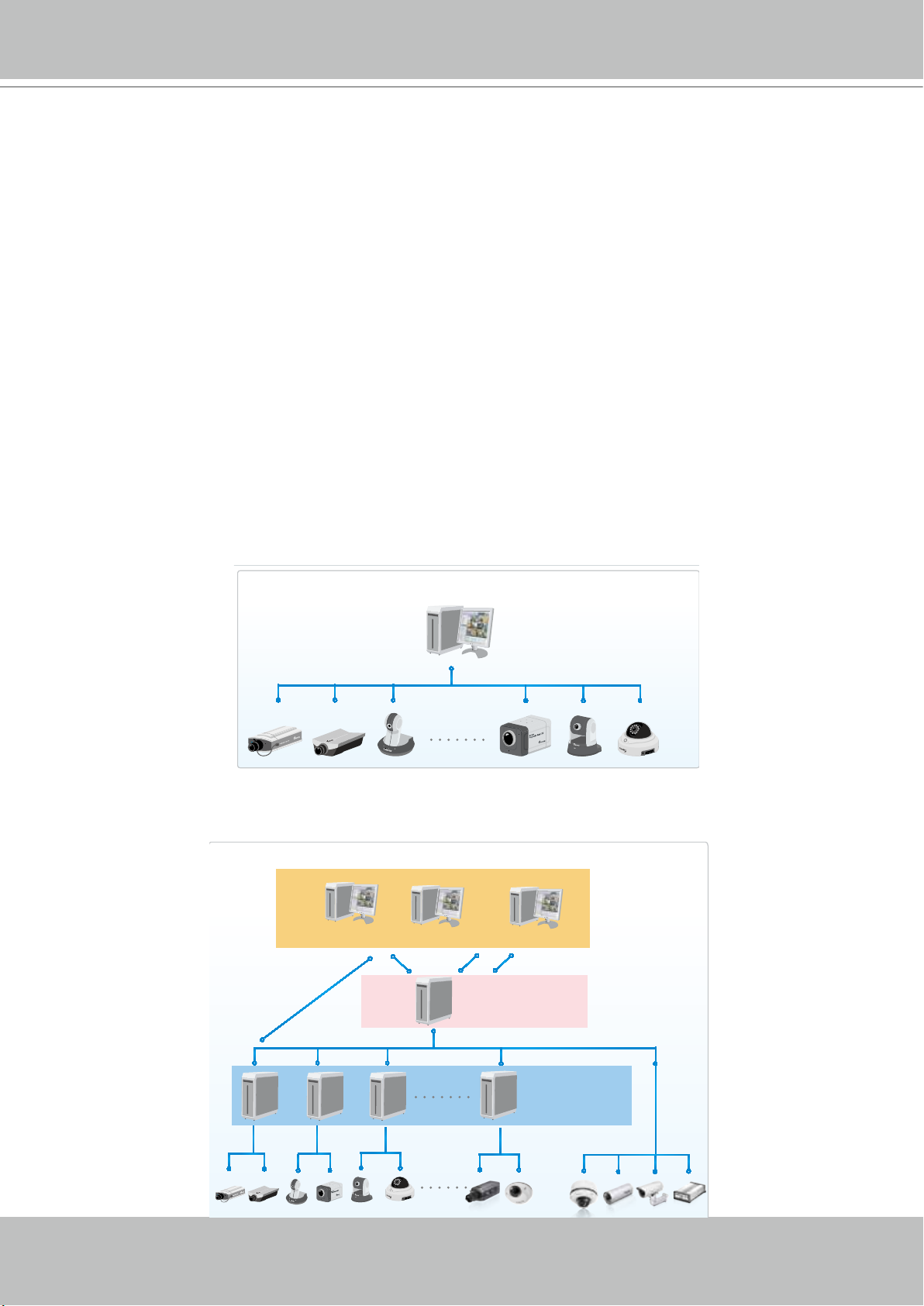
Usage Scenario
The powerful management scalability of VAST makes it suitable for managing small- to largescale structures.
For users that manage only a few cameras, we recommend installing the client and server
components on the same computer. A host with all of the three components installed is recognized
as a stand-alone site. All the functions can be simultaneously performed on one single site.
For users who manage large-scale surveillance deployments, please plan the hierarchical
structure rst. Then you can start to add cameras to each station and connect these sub-stations
to the root station. The whole hierarchical management system is thus constructed.
Local Server Structure
Remote Server Structure
Router
VAST LiveClient
Login
Network Cameras
Client
VAST Playback
Login
Stand-alone site
VAST Server
VAST LiveClient
VAST Playback
Web Console
VAST CMS Server
(Root station)
Router
Software NVR
VAST / ST7501 Server
(Sub-stations)
User's Manual - 11
Page 12
VIVOTEK - A Leading Provider of Multimedia Communication Solutions
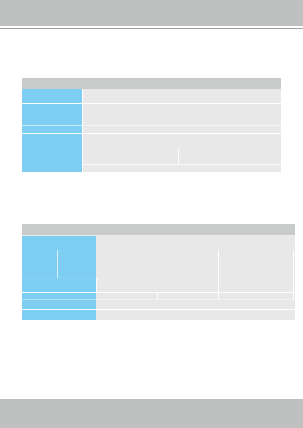
Technical Specications
Technical Specifications
Version
1.9
General
Maximum N umber of
Cameras
Maximum N umber of
Server
Maximum N umber of
Clients
Support OS
Suppor t Web Browser
Mobile Support
Virtua l Matrix Support
Devices Pack
Unlimited ( Please Refe r to System Requir ements Bel ow)
Unlimited ( Please Refe r to System Requir ements Bel ow)
Unlimited
Window s 8, 7, Vista, XP
Wind ows Ser ver 2012, 2008, 2003, 2000
Internet Explorer 11/10/9
iViewer (iOS/Android)
VAST Matri x (Please Refer to Syste m Requirement s Below)
CSV file U pdate
LiveView (Local D isplay)
Max. Channel
Layout
Stream Application
View Application
Fisheye Dewarp Mode
64-Channel (With dual monitor)
Multi Lay out display: 1x1, 2x 2, 1+5, 3x3, 1+12, 4x4, 5x5,
1+31, 1P+2, 1P+6, 1P+8, 2V, 3V, 4V, 2V+3
Single Layout display, Full screen display, Sequential
display
Stream Se lection & Au to Stream Size
Drag & Drop
Remote I/O Cont rol
PIP (Digit al Zoom)
Instant Replay
De-interlace
Video Dis play Mode (A spect Ratio)
Fisheye Disp lay Mode:
Regular: 1O, 1P, 1R, 1O3R, 4R
Wall Mount: 1P2R, 1P3R
Ceiling/F loor Mount: 2P, 4R Pro, 1O8R
Playback
Max. Channel
Layout
Playback Mode
Playback Control
Search Mode
16 Ch ann el
Multi Lay out display: 1x1, 2x 2, 1+5, 3x3, 1+12, 4x4
Single Layout display, Full screen display, Sequential
display
Asynchronous & Synchronous
Play, Rewind, P ause, Stop, Next / Prev ious Video Start ,
Next / Pre vious Frame , 1/8X ~ 64X Speed Control,
Bookmark
Browsin g, Date & Time (Fas t), Event, Boo kmark, Ala rm,
Log, Timeline, Timeline Scale
Video
Video For mat
Video Resolution
Video Enhancement
MJPEG, MPEG 4, H.264 AVC,H.264 SVC
Up to 5 Megap ixel
Basic Mode: Brightness, Contrast, Saturation, Hue
Intellig ent Mode: Defo g, Rain, Snow, Fire / Smoke
Audio
Audio Format
Audio Capability
Audio Control
G.711, G.726, AM R, AAC
Two W ay
Mute, Bro adcastin g & Sound Play
Record
Recording Time (sec.)
Recording Stream Type
Recording Stream
Recording Mode
Recording Setting
Recording File Format
External Storage
Recording
Pre-Re cord: 3-15, Post-Record: 10-60
Unicast
Single
Continuo us, Schedule, M anual, Event, Acti vity Ada ptive
Streaming
Recycle (un it: Size or Day)
3GP
NAS (SMB & CI FS)
System Requirements
VAST Server
4Mbps Each C hannel
CPU
RAM
Hard Drive (Enterprise Mo del Only)
Graphics Adapter
Netwo rk Interface Car d
* Each reco rding group can be se tup to only 60 channels
VAST LiveV iew & Playback
720P,4Mbps,H.264*
1080P,4Mbps,H.264**
CPU
RAM
Graphics Adapter
Netwo rk Interface Car d
* Display re quirements of the 3MP f isheye camera is e qual to a 720P camera.
** Display r equirements of the 5MP f isheye camera is e qual to a 1080P camera.
If install ing Server & Client i n the same PC, over all loading of the PC is t o be evaluated.
Upto 64 Chan nel
2nd Generat ion Intel® Core™ i3 Process ors or above
4 GB or above
Single Reco rding Group with On e Hard Drive
Direct X 9 compatible 1GB graphi cs card
100 0/100/ 10 Eth ern et
8CH
4CH
2nd Generat ion Intel® Core™ i3 Process ors
2 GB or above
Direct X 9 compatible 1GB graphi cs card
100 0/100/ 10 Eth ern et
Alarm Management
Alarm Period (sec.)
Alarm Filter
Alarm Setting
Sch edul e Type
Camera Event
Camera Status
Substation
Storage Status
Station Status
Event Action
Max. 30
Name, Tim e, Source, Eve nt Type
LiveView A larm Notificat ion: Fixed & Popup
Alert S ound
Continuous, Schedule, Manual
Motion, D I/O, Video lost/re store, PIR, Tampe ring,
Temperature, I R, IVA, P-PTZ
Connection Status, Recording Status, Recording Error
Substation Connection Status
Connection Status, Ca pacity Status
License St atus, Netw ork Status, Virtu al Memor y Status
Email, Sta rt Recording, Set D O, GSM Short Me ssage, HT TP
& Client Notification
eMap
Source
Marked
Event Notification
Import Picture
Add, Remove , Direction Contr ol, PTZ Con trol & Indica tor
LiveV iew
Event Icon Light Flash
PTZ
PTZ/ePTZ Control
PTZ/ePTZ Operation
PTZ Op eration Mo de
Panel Con trol & Mouse Cli ck Control
Direct ion Control, H ome, Zoom, Focus, Iris , Preset, Patr ol
(Group), Pan, Sto p, Speed
Click to Move & C ontinuous Mo ve
Export
Print
Snapshot
Export file
Select ion Window s & All Windows
BMP & JPEG
AVI, 3GP & EXE
Backup
Schedule
NAS (SMB & CI FS)
System
User Management
User Level
User Control
Date & Time
Network
Language
Authenti cation: Ba sic Account / Win dows AD Accou nt
Administr ator, Power User, User, Oper ator & Guest
Permission, Accessible Cameras & Accessible Substation
Sync PC
DDNS, SM TP, UPnP & Proxy
Czech, English, French, German, Italian, Japanese,
Persian, Portuguese, Russian, Spanish, Simplifie d
Chinese, Traditional Chinese
Device Integration
Joystick
I/O Box
VIVOTEK U SB Joystick
All Windo ws® Compatible USB Joy stick
Advant ech ADAM-6 000
Camera Integration
Camera Insert
Basic Setting
Connection Setting
Video Setting
Audio Setting
Remote Focus
NTP Setting
ONVIF
ONVIF Discover
Manual & Se arch
UserName, Password & Camera model detection
Configuration Protocol: HTTP,HTTPS
Streaming Protocol: TCP,UDP,HTTP,HTTPS
Video Str eam, Compre ssion, Resolut ion, FPS, Vi deo
Quality
Compression & Bitrate
Manual Fo cus Adjustment & Fu ll Rang Scan
IP Address (N TP Server or VAST S erver) & Updating
interval
Version 2.2 (by project)
Discover t he other bran d camera through " Insert Cam era"
Advanced Features
VIVOTEK E xclusive
Feature
16C H
10C H
2nd Generat ion Intel® Core™ i5 Process ors
4 GB or above
Panoramic PTZ
Seamless Recording
Upto 120 Channel
Duplex Re cording Group with Two Har d Drive*
32CH
18C H
2nd Generat ion Intel® Core™ i7 Process ors
4 GB or above
Ver 3.2
12 - User's Manual
Page 13

VIVOTEK - A Leading Provider of Multimedia Communication Solutions
VAST Server Functionality
Centralized management site for all the logged in clients
Maintain the configuration of the hierarchical management list
Hundreds of video recording channels
Store recorded data onto multiple networked or local hard disks
Live video for the local/remote LiveClient users
Retrieval of recorded video for the local/remote Playback users
Zero latency database recovery
LiveClient is the management interface to your VAST server. The server-related settings are
made via the VAST LiveClient utility. The convenient and intuitive user interface on VAST
LiveClient provides access to camera, live monitoring, and recording congurations.
User's Manual - 13
Page 14
VIVOTEK - A Leading Provider of Multimedia Communication Solutions
VAST LiveClient Functionality
Server function control
Hierarchical station management
User account management
Recording storage management
Recording schedule management
Recorded data backup
Event trigger management
Flexible video live view layout
Dual screens for a maximum of 64 or more channels for simultaneous monitoring
1x1, 2V, 1P+2, 3V, 2x2, 4V, 2V+3, 1+5, 1P+6, 3x3, 1P+8, 1+12, 4x4, 5x5, 1+31 monitoring
layouts (V stands for vertical layout)
1P+2, 1P+6, and 1P+8 Panoramic PTZ layouts
Multiple video viewing pages
Virtual Matrix for video wall display
Intelligent PiP function
E-map for overall management
Network storage for recorded video
Convenient switching among multiple monitors
PTZ / E-PTZ operation panel for camera control
Supports two way audio
Instant playback for event recording
Instant replay for immediate playback
Supports joystick control
Remote configuration for network cameras
14 - User's Manual
Page 15

VIVOTEK - A Leading Provider of Multimedia Communication Solutions
VAST Playback Functionality
Browse the database of recorded video from the server
Flexible video playback layout
Maximum 16 channels with simultaneous playback
1x1, 2V, 3V, 2x2, 4V, 2V+3, 1+5, 3x3, 1+12, 4x4 video playback layouts
Supports powerful playback functions
1/8x, 1/4x, 1/2x slow-down playback
2x, 4x, 8x, 16x, 32x, 64x video playback speed
Intelligent PiP function
Supports convenient evidence and data exporting
Export media files of recorded video
Supports snapshot and print out
Supports convenient switch among multiple monitors
Search engine:
Time search
Event search
Bookmark search
Alarm and Log search
Playback while recording
Support synchronous/ asynchronous playback
User's Manual - 15
Page 16
VIVOTEK - A Leading Provider of Multimedia Communication Solutions
Minimum System Requirements
Before installing the VAST software, please make sure your system meets the following
recommended minimum system requirements.
If you would like to install ST7501 Server only, please follow the requirements as below:
Server
Operating System
Recording Channels
(4Mbps per CH)
CPU 2nd Generation Intel
RAM 4GB or above
Network Interface Card Ethernet, 1 Gbit recommended
Graphics Adapter
Hard Disk Type
* Each recording group can receive recordings for 60 channels.
Windows Server 2000, 2003, 2008, 2012 / Windows XP Professional, Windows
7, Windows 8
up to 64 CH Up to 120CH
®
Core™ i3 Processors or above
DirectX 9 compatible 1GB graphics card
Single recording group w/ one
HDD
SATA, SCSI, SAS (7200 rpm or faster) in NTFS format
Two recording group w/ two HDDs*
If you would like to install both the server and client programs, please follow the requirements as
below:
LiveClient and Playback
Operating System
Clients
(Display
Channels)
CPU
RAM 2 GB or above 4GB or above 4GB or above
720P,4Mbps,
H.264*
1080P,4Mbps,
H.264**
Windows Server 2000, 2003, 2008, 2012 / Windows XP Professional, Windows
Vista, Windows 7, Windows 8
8CH 16CH 32CH
4CH 10CH 18 CH
®
2nd Generation Intel
Core™ i3 Processors
2nd Generation Intel®
Core™ i5 Processors
2nd Generation Intel® Core™
i7 Processors
Network Interface Card Ethernet, 1Gbit recommended
Graphics Adapter
* Display requirements of the 3MP sheye camera is equal to a 720P camera.
** Display requirements of the 5MP sheye camera is equal to a 1080P camera.
DirectX 9 compatible 1GB graphics card
If installing Server and Client on the same PC, the overall loading on the PC is to be evaluated.
16 - User's Manual
Page 17

VIVOTEK - A Leading Provider of Multimedia Communication Solutions
Only users with Administrator privileges can install or use VAST on a Windows Vista system.
The required hard disk space will depend on the video settings, the number of network cameras and recording
group settings. Please add more hard disks if you want to extend the system.
Below are approximate numbers for a week-long recording. The actual storage space required also depends on
imaging parameters, e.g., a complex retail environment that involves many moving objects requires more pixel
data to be transmitted over network than a simple environment such as a parking lot.
32-CH, VGA, about 1 week recording: 750 GB
64-CH, VGA, about 1 week recording: 1TB x 2
32-CH, 2-megapixel, about 1 week recording: 2TB x 2
64-CH, 2-megapixel, about 1 week recording: 2TB x 4
User's Manual - 17
Page 18
VIVOTEK - A Leading Provider of Multimedia Communication Solutions
VAST Installation
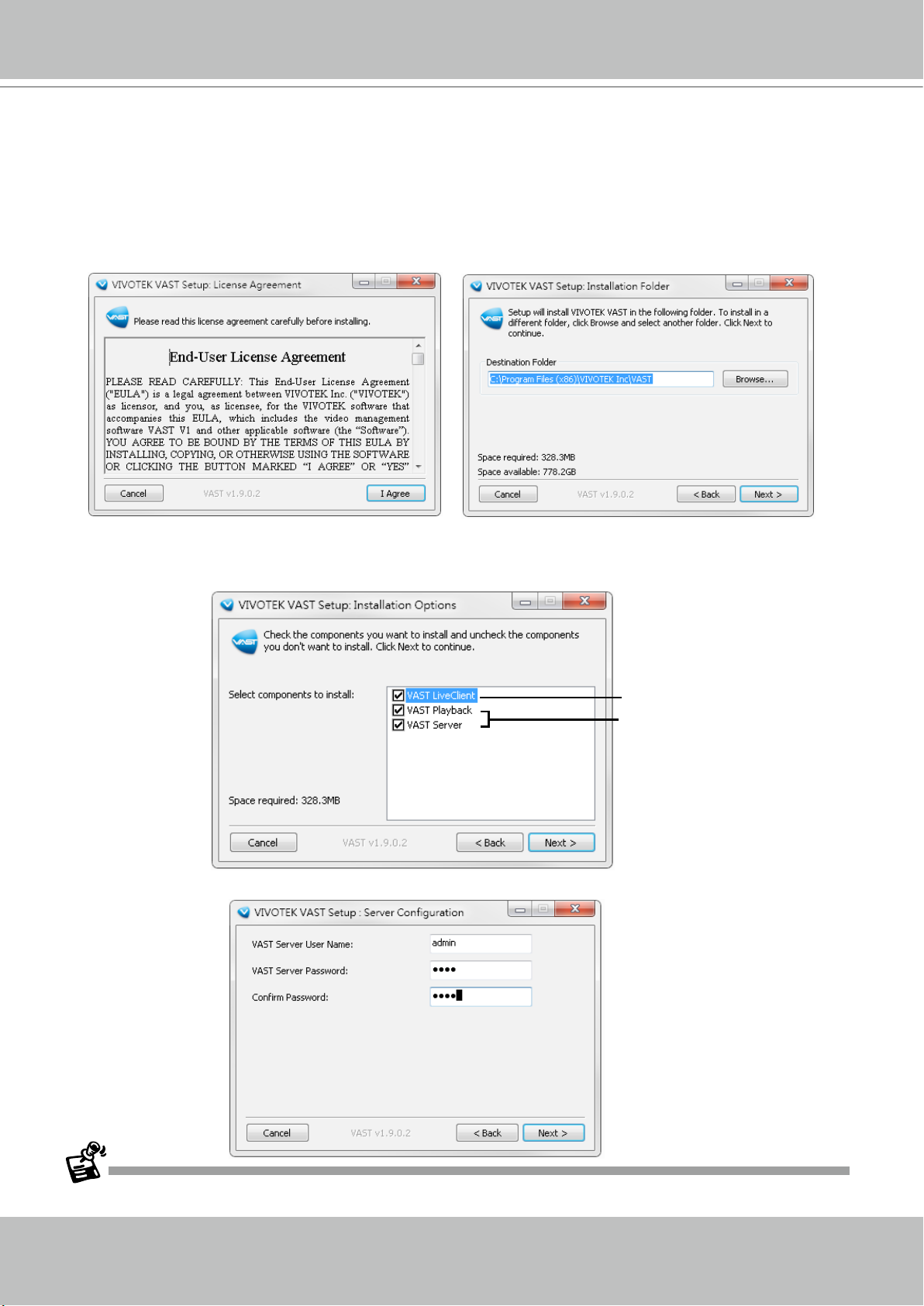
Installing the VAST Software
1. Run VAST_Setup.exe on your computer. Click I ACCEPT the License Agreement and specify a
location to install the program.
2. Select the items you want to install, then click Next to continue.
If you want to install both VAST Server component and Client components, please follow the steps
below to install the database.
Server component
Client components
3. Assign a username and password for the VAST Server and click Next to continue.
Please record the user name and password for login later.
18 - User's Manual
Page 19

VIVOTEK - A Leading Provider of Multimedia Communication Solutions
4. An SQL Lite database is automatically installed on your server. In order to avoid conflicts among
different databases, we suggest you remove the original database from your host.
Once you have created a user account for a VAST station, you can login to VAST Server from any computer over
the network through the LiveClient and Playback utilities.
User's Manual - 19
Page 20
VIVOTEK - A Leading Provider of Multimedia Communication Solutions
VAST Server
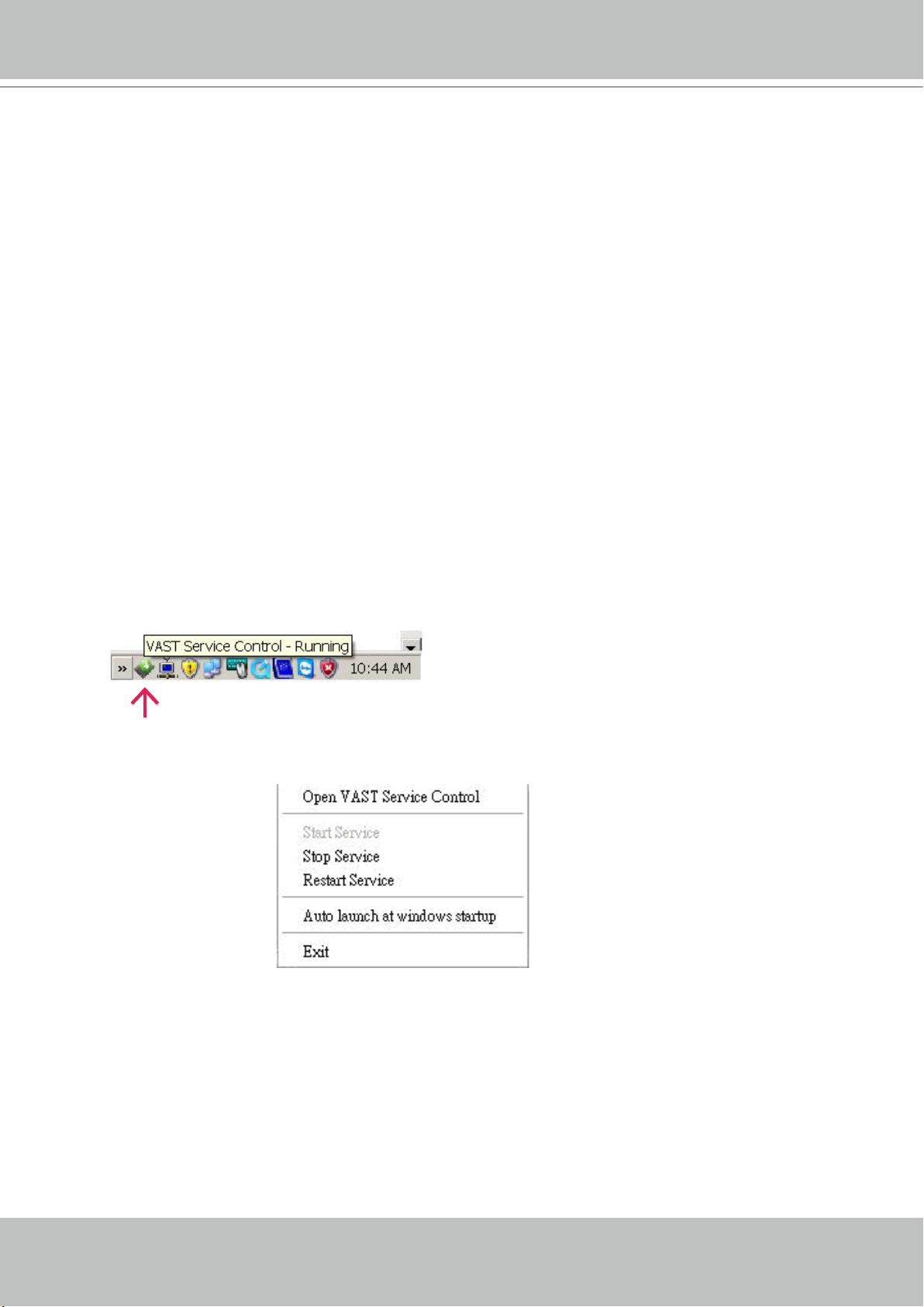
Activating the VAST Server
VAST Server is a service program that will run automatically when your VAST station starts.
Users can also deselect the Auto launch option at windows startup on the VAST Service Control
program tray. The program tray icon can be located on Windows tool bar.
How to Congure the Server
Please follow the steps below to congure the VAST Server:
1. Find a local/remote computer that has installed VAST LiveClient.
2. Activate VAST LiveClient and login to the target VAST Server.
3. Congure the server using the VAST LiveClient user interface.
How to Stop/Reboot the Server
Please follow the steps below to stop/reboot the server:
1. Click on the VAST Service Control program tray icon in the toolbar.
2. There are 3 options: Start Service, Stop Service, and Restart Service. It’s selectable by a right-click on
the Service Control program tray icon.
20 - User's Manual
Page 21
VIVOTEK - A Leading Provider of Multimedia Communication Solutions
VAST LiveClient Configuration
Activating the VAST LiveClient and Logging in to a VAST Server
VAST LiveClient allows you to monitor live video from cameras managed by the VAST Server; it
is also the main user interface for server function control.
After installing the VAST LiveClient program, please follow the steps below to activate VAST
LiveClient:
1. Run the VAST LiveClient program.
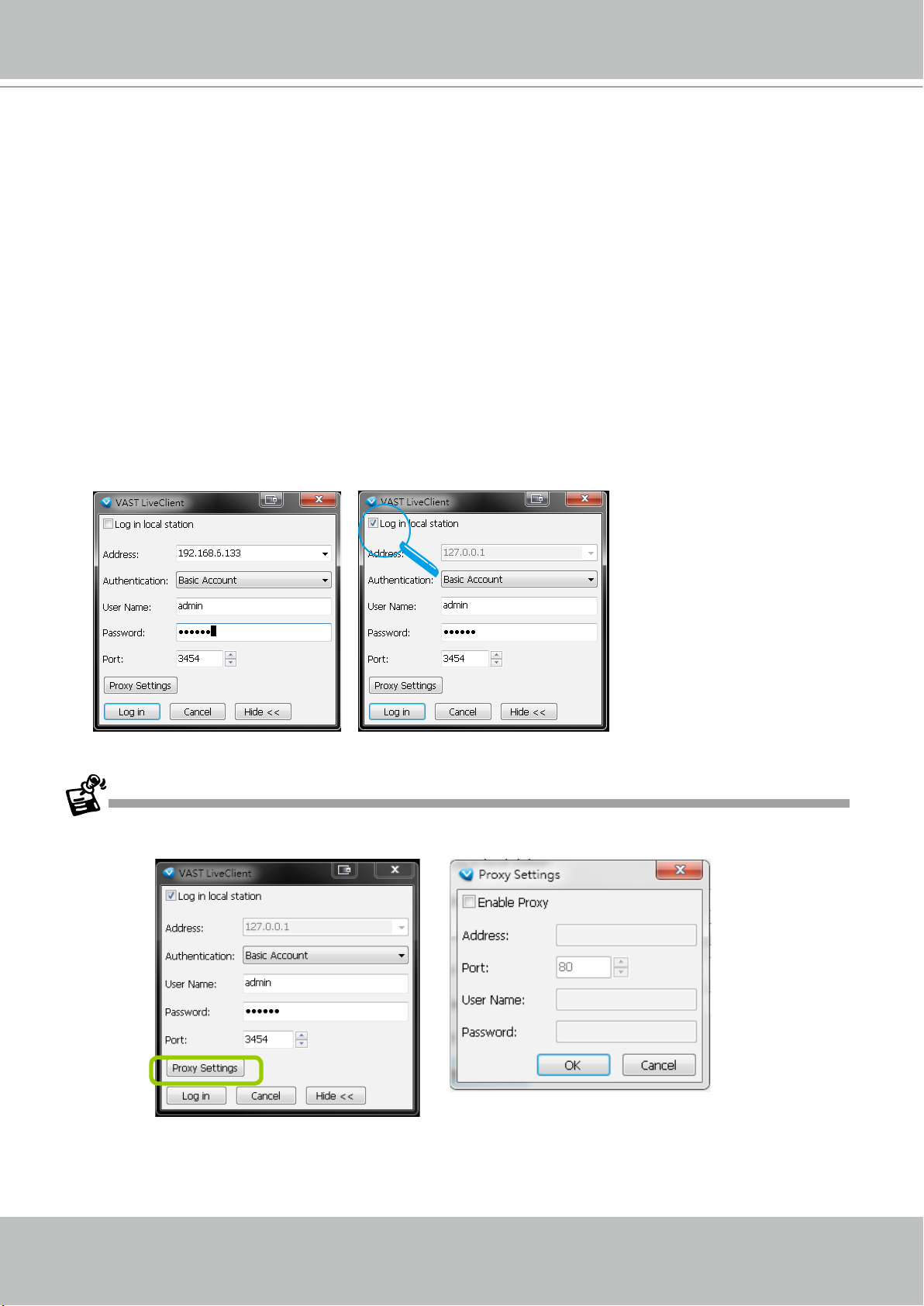
2. A Login window will pop up. Enter the information as shown below:
If you want to login to a remote VAST Server, enter the IP Address, User Name, Password and the
Communication Port of the target server correctly. Click Login to log in to the target server.
If you want to login to a local host that is running VAST Server, check the Login local station checkbox, then the local IP Address will be displayed automatically. Enter the User Name, Password,
and Communication Port of the local server for login. Click Login to login to the target server.
Please refer to page 86 for
how to enable and configure
Windows AD accounts.
3. The VAST LiveClient monitoring window will prompt.
If your network environment need to set up proxy, click More >> to extend the login window, then click Proxy
Settings to open the dialog. Then enter related information to link to your proxy server.
Available functions of the VAST LiveClient program will be enabled according to the role of your login account.
For more details about the privileges of the user account, please refer to How to Manage User Accounts on
page 83.
User's Manual - 21
Page 22
VIVOTEK - A Leading Provider of Multimedia Communication Solutions
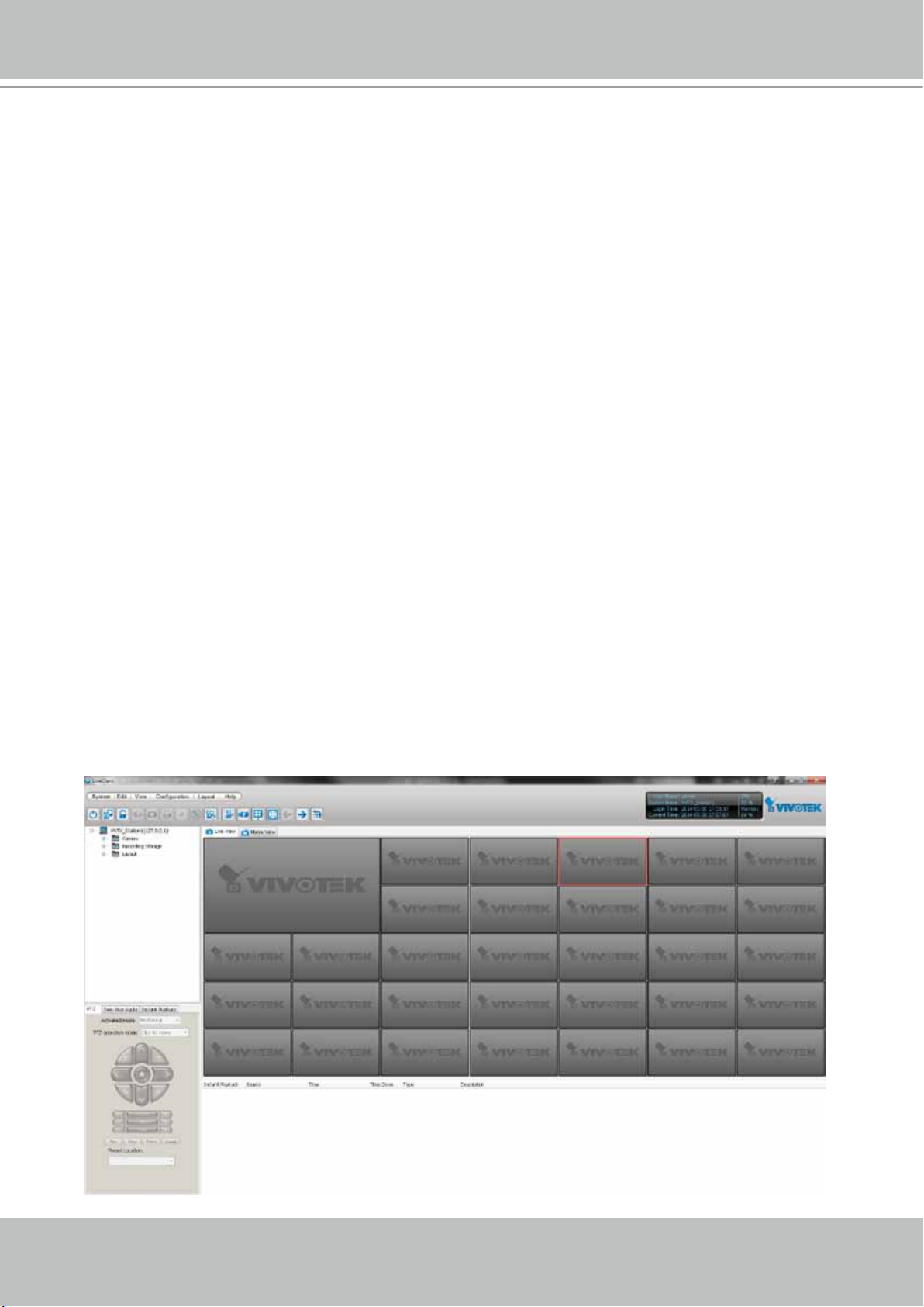
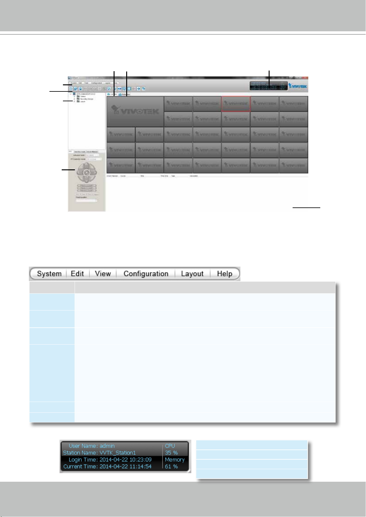
VAST LiveClient User Interface
B
E
F
G
A
C
D
A. Menu bar B. Quick access bar C. Hierarchical management tree
D. Camera control panel (PTZ / Two way audio / Instant Playback control panel)
E. Live view window F. Matrix view window G. Status panel H. Alarm window
H
Menu Bar
Menu Item Drop-down Options
System
Edit
View
Conguration
Layout Start Rotating (Stop Rotating) / Save to / Delete / Choose
Help About / License
Lock / Enable Click On Image (Disable Click On Image) / Language / Second View / E-map /
Launch Playback / Logout / Exit
Manually Begin Recording (Stop Manual Recording) / Snapshot / Print / Record to EXE (3GP,
AVI) / Snapshot Zoomed Image / Print Zoomed Image / Find
PTZ Panel / Two Way Audio Panel / Instant Playback Panel / Alarm Window / Full Screen /
Minimize / Matrix View
Camera Management (Insert Camera / Update Camera / Delete Cameras / Batch Insert
Cameras / Camera Configuration) / Station Management / User Management / Association
Management / Alarm Management / Virtual Matrix Management (Matrix Management / Matrix
View Settings) / Station Settings (General Settings / Network Settings / Recording Storage
Settings / Recording Schedule Settings / Scheduled Backup Settings / Server Settings / Relay
Settings) / Client Settings (Snapshot Settings / Recording Settings / View Settings / General
Settings / Joystick Settings / Proxy Settings / PiP Settings) / Video Enhancement (Basic Image
Adjustment / Defog)
Status Panel
User Name
Station Name (IP Address)
Login Time (yyyy-mm-dd hh:mm:ss)
Current Time (yyyy-mm-dd hh:mm:ss)
22 - User's Manual
Page 23
VIVOTEK - A Leading Provider of Multimedia Communication Solutions
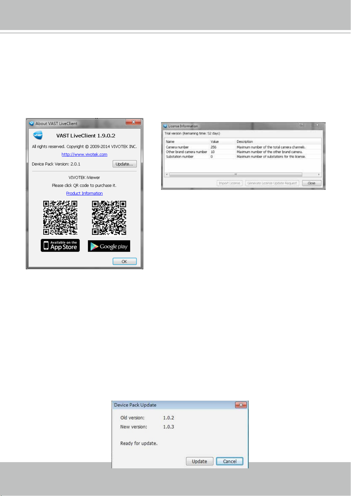
Help Panel
The Help panel provides software revision information and the access to the associated iViewer
software in either the iOS or Android version. You can also click on the License button to review
the number of cameras and manageable substations.
If necessary, you may also use the Import License button to activate the functionality you
separately purchased or generate a request for a license request.
Device Pack Update
A Device Pack consists of information of new VIVOTEK cameras or the updated information
for previous models, such as various congurations including resolutions, FPS, DI/DO, etc. For
example, some panels, such as the PTZ panel, may not be available for a new PTZ camera.
Your VAST server might not recognize the features of the latest VIVOTEK cameras. With the
Device Pack, you can congure and implement the latest VIVOTEK models without the need
to upgrade the entire VAST software to acquire the associated information. Please visit: http://
www.vivotek.com/web/product/productdetail.aspx?Model=VAST. For congurations not specied
in the device pack, you can still open a web console with individual cameras to change their
conguration.
You can consult VIVOTEK's technical support for the latest Device Pack [CSV files (*.csv)],
and use the Update... button in the Help window to replenish camera information. The update
information will be displayed, and the update process is completed almost immediately.
User's Manual - 23
Page 24
VIVOTEK - A Leading Provider of Multimedia Communication Solutions
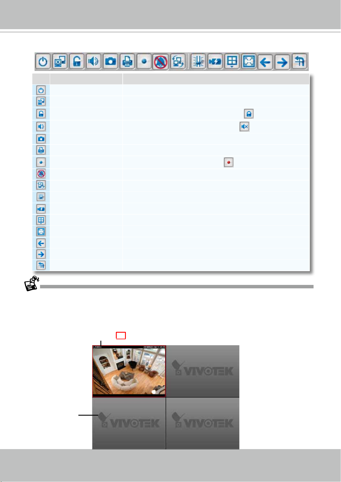
Quick Access Bar
Icon Function Description
Exit Exit the system
Logout Log out from the current station
Lock Click to Lock the system for security concerns (
Volume Adjust the audio volume of the current video ( Mute)
Snapshot Capture pictures from the focus live video cell
Print Print out the pictures of focus live view window or all live video cells
Record to Media Record media in EXE/3GP/AVI format (
Alert Sound Play sound when an event triggers
Switch Screen Switch the current window to another screen
Adjust SVC Level Dynamically adjust the SVC control over frame rates
Remove All Connections Remove all live videos from the live view window
Layout Change the layout of the live view window
Full Screen Maximize the live video cell
Page Up Switch to the previous live view page
Page Down Switch to the next live view page
Start / Stop Rotating Start or stop live view layout rotating
Recording Media)
Unlock the system)
Some buttons will be disabled if the selected devices do not support the corresponding functions.
Live Video Monitoring Window
The "VIVOTEK" logo is displayed where no camera has been assigned to a video cell.
The red frame ( ) represents the current selection.
Video Cell
24 - User's Manual
Page 25
VIVOTEK - A Leading Provider of Multimedia Communication Solutions
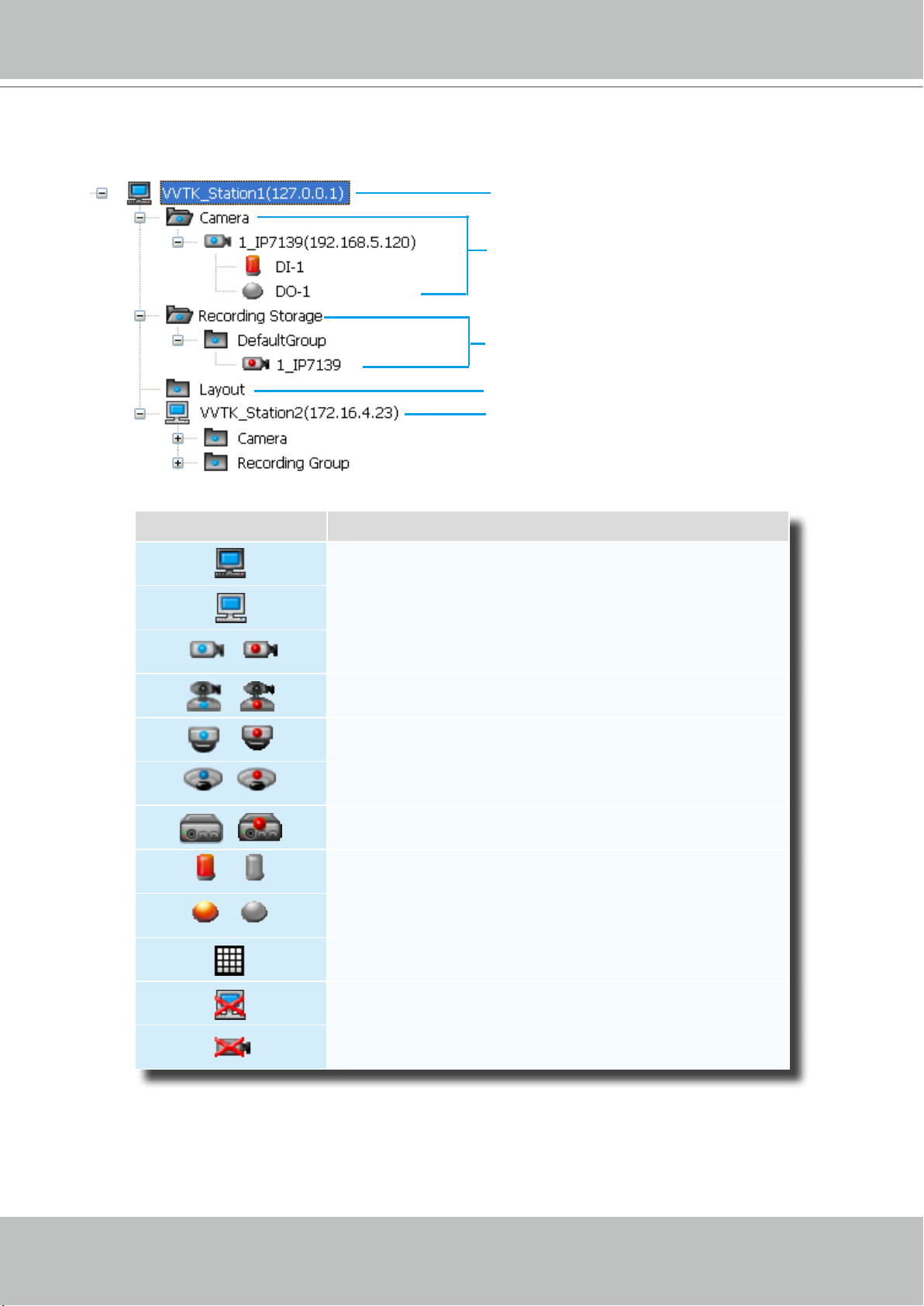
Hierarchical Management Tree
Root Station Name (IP address)
Connected devices listed under the root station
Camera name (IP Address)
Connected devices that have been assigned to
the default recording storage
Layout list
Sub-station Name (IP address)
Icon Description
A station (The host that’s installed with VAST Server)
A station (The host that’s installed with ST7501 Server)
/
/
/
/
/
/
/
VIVOTEK xed network camera (or ONVIF cameras)
Red dot signies that the camera is recording.
VIVOTEK PTZ network camera
Red dot signies that the camera is recording.
VIVOTEK dome network camera
Red dot signies that the camera is recording.
VIVOTEK sheye network camera
Red dot indicates that the camera is recording.
VIVOTEK video server
Red dot signies that the video server is recording.
Digital input on / off
Digital output on / off
A layout of the live monitoring window
A station that’s not able to be connected currently.
A device that’s not able to be connected currently.
User's Manual - 25
Page 26
VIVOTEK - A Leading Provider of Multimedia Communication Solutions
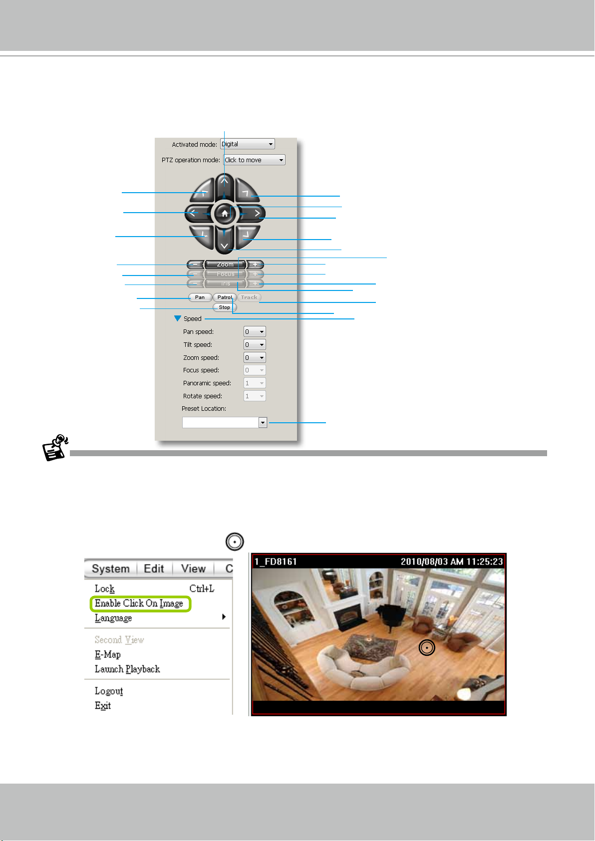
Camera Control Panel
Pan/Tilt/Zoom (PTZ) Control Panel
Up
op left
T
Left
Top right
Return to home position
Right
Bottom left
Bottom right
Down
Zoom out
Focus near
Close
Start to auto pan
Stop auto pan/
patrol
Zoom in
Focus far
Auto iris
Start to auto patrol
Speed control
Auto focus
Open
Auto Tracking
Drop-down list of preset positions
There are two types of PTZ control: Digital (E-PTZ for megapixel cameras) and Mechanical (PTZ cameras or
fixed cameras with camera control via RS-485). If the connected cameras support PTZ/E-PTZ function, the
PTZ option(s) will appear on the drop-down list. For detailed camera control settings, please refer to the user's
manual that came with VIVOTEK network camera .
Click System > Enable Click On Image to use the mouse for the control of the PTZ and E-PTZ functions in the
video cells for linked cameras. An icon
will appear in the video cell as shown below.
You can control the PTZ function through joystick as well. For more information regarding to the joystick
conguration, please refer to instructions on page 166.
26 - User's Manual
Page 27
VIVOTEK - A Leading Provider of Multimedia Communication Solutions
VIVOTEK's latest SD8xxx speed dome series supports the Continuous Move control. The
"Click to move" enables one movement by every mouse click on the PTZ buttons.
When Continuous Move is enabled from the PTZ panel, you can click and hold down the
mouse button on an arrow key to command the camera to continue moving to that direction.
The move will stop when you release the mouse button. Also, if the pan/tilt/zoom/focus speed
is congurable for a PTZ camera, you can use the Speed button to display the speed options:
pan, tilt, zoom, focus, panoramic, and rotate speeds.
For sheye cameras, two more options will be available: Panoramic speed and Rotate speed.
These two options apply to the onscreen control for the Panoramic and Regional views.
In addition to the PTZ panel, the following hot key combinations are also available:
Ctrl + NumPad (PTZ control)
Up Ctrl + 8
Left Ctrl + 4
Home Ctrl + 5
Right Ctrl + 6
Down Ctrl + 2
Focus (Far - Near) Ctrl + 1 Ctrl + 3
Zoom (Out - In) Ctrl + 7 Ctrl + 9
Pan Ctrl + /
Stop Ctrl + *
Patrol Ctrl + -
Preset locations (pre-
congured by users)
Full screen Ctrl + F
Single view Ctrl + V
Previous layout page Alt + PageUP
Next layout page Alt + PageDown
First layout page Alt + Home
Last layout page Alt + End
Snapshot Ctrl + S
Stop alarm Ctrl + A
Mute audio from
current stream
Start/ Stop rotation Ctrl + O
Ctrl + 0~9 (number keys above the
alphabetic keys)
Ctrl + M
User's Manual - 27
Page 28
VIVOTEK - A Leading Provider of Multimedia Communication Solutions
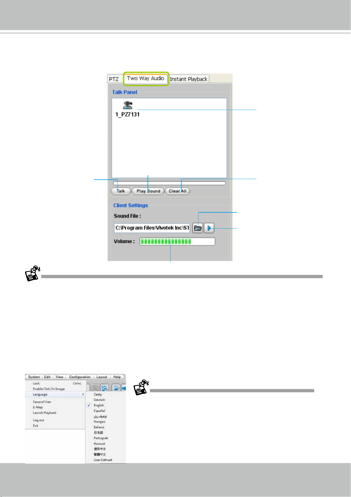
Two Way Audio Control Panel
The two way audio function allows the user to remotely communicate with people nearby the
network camera.
Selected device that
can use the two way
audio function
Click to play sound from the camera
Click to talk
Remove all cameras
from the Talk Panel
Select sound from the
le list
Click to play the selected
sound on the client's side
Click to adjust volume
For detailed information about How to Use the Talk Panel, please refer to page 139.
Only cameras that come with the two way audio function can be added to the Talk Panel.
Language Selection
VAST currently supports multi-lingual user interfaces including:
ñol, Farsi, Français, Italiano,
日本語
, Português, Русский,
簡体中文
English, Česky, Deutsch, Espa-
繁體中文
,
. If you want to select
another language for the interface, please click System > Language on the menu bar to select
the desired language. Please note that if you want to change the language option, a message
will prompt to remind you to restart the system.
28 - User's Manual
If you want to use "User Dened" language, please prepare images and
language strings, and upload the les to the following folders:
...\VAST\Client\LiveClient\language\zz_UD (language string)
...\VAST\Client\LiveClient\image (images)
Page 29
VIVOTEK - A Leading Provider of Multimedia Communication Solutions
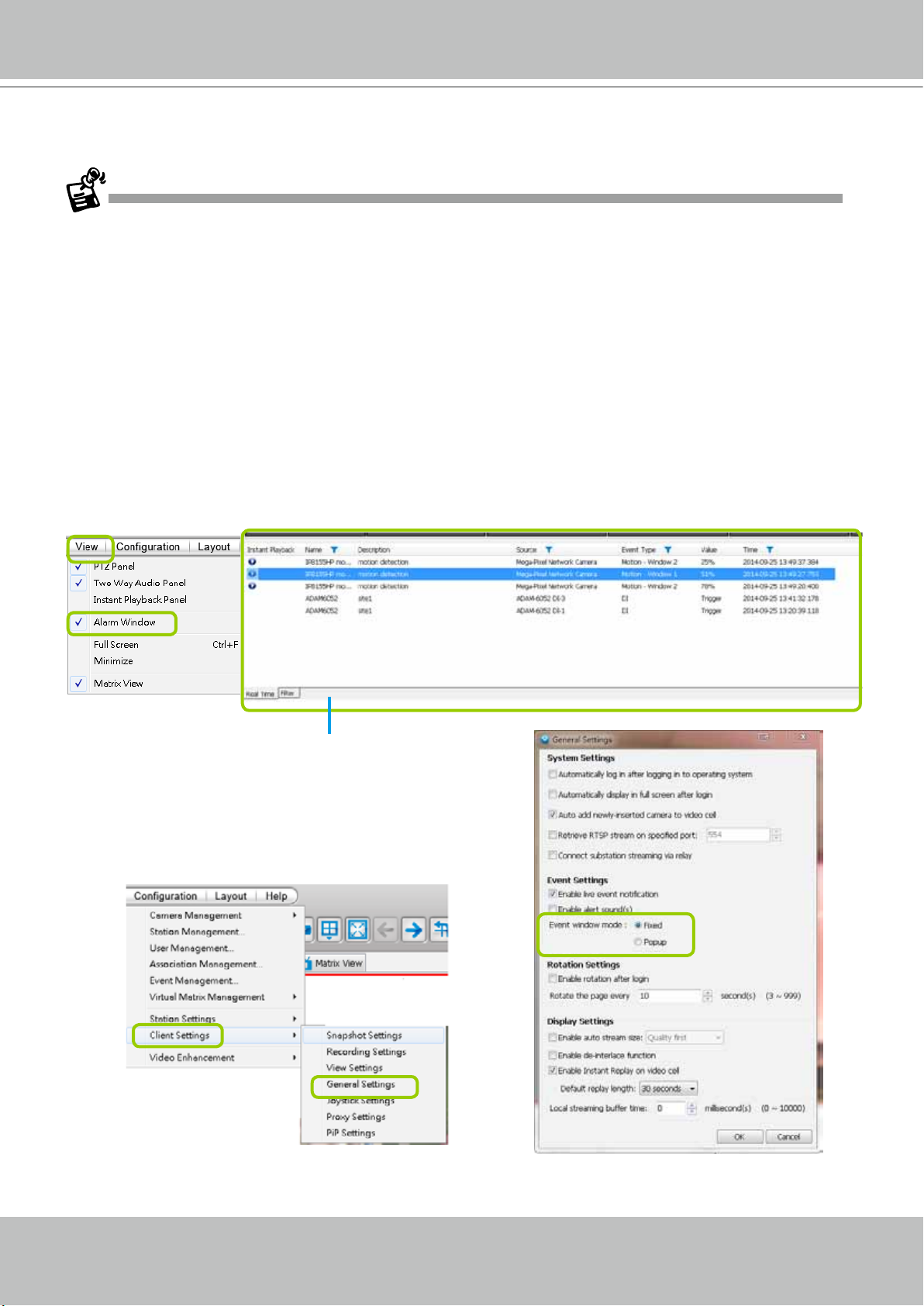
Alarm Window
• Only the alarm-related messages will be displayed in this window. An Alarm is a conguration
consisting of triggers and reactions set to activate during a specific period of time. The
Alarm-related settings is congured in Conguration > Alarm management. See page 93
for more information.
• For the event messages of the overall system operation, please refer to the Playback > Log
viewer.
• If a VAST server is reset, the Alarms will disappear from the Alarm window. You can go to the
Playback utility and use the Alarm search function to retrieve the past events.
Click View > Alarm Window to open a window showing the real-time information for event
triggers. If you want to hide this window, deselect this option on the menu bar.
Event Window
The default Alarm window is set to be fixed on the
bottom of the LiveClient. If you want to change
the Alarm window as a popup page, please click
Configuration > Client Settings > General
Settings to switch the modes.
User's Manual - 29
Page 30
VIVOTEK - A Leading Provider of Multimedia Communication Solutions
The Event Type eld in the Alarm window shows the event category and another eld Value displays
the percentage of motion in the detection window. You can go to the Conguration setting page of the
connected device to set the percentage.
Video(TCP-AV)
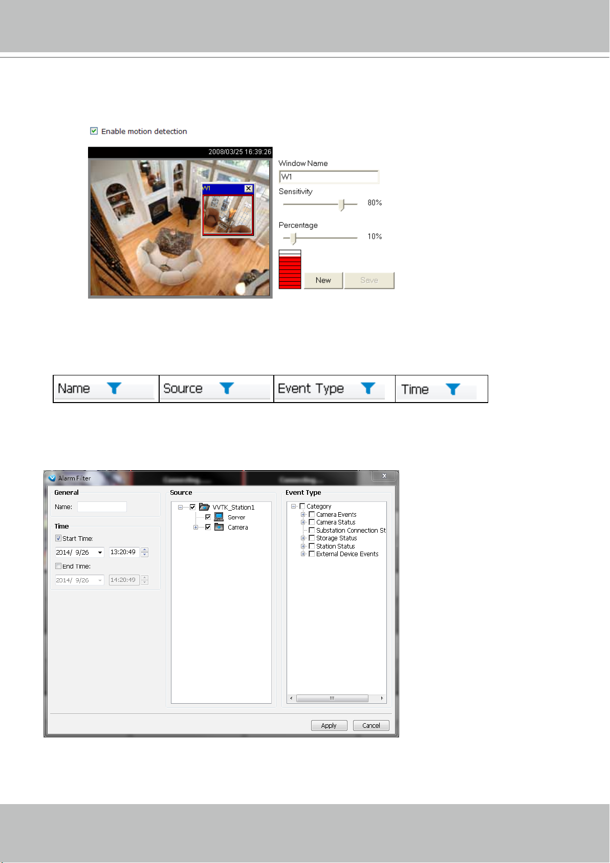
Alarm Filter
On the Alarm panel, a list of alarms will be displayed. Click on the attributes with a funnel icon.
The Alarm Filter window will prompt. Use the Name, Time selector, and the checkboxes in the
Source and Event Type panes to specify what kinds of alarms will be displayed.
30 - User's Manual
Page 31

VIVOTEK - A Leading Provider of Multimedia Communication Solutions
For example, you can set up a lter to display the alarms with a name associated with a specic
camera, such as "bullet on the corridor." The name of the alarm is congured in Conguration
> Alarm management on page 93.
Use the Filter tab at the bottom of the Alarm window to display a different sorted result.
User's Manual - 31
Page 32

VIVOTEK - A Leading Provider of Multimedia Communication Solutions
Instant Playback
Check View > Instant Playback to open the window on the panel. The entries listed in the
Event panel are the short recordings made from triggered events.
Deselect this item if you want to hide this window.
Instant Playback Window with a slide bar, play, pause, and stop function
The recorded media that was triggered by an event will be indicated with a playable
icon.
You can double-click an event on the list to playback the recorded video. Each event contains
a video clip of 20 seconds in length. (The default recording data of an event is 20 seconds. For
more information about event recording, please refer to page 112. )
32 - User's Manual
Page 33

VIVOTEK - A Leading Provider of Multimedia Communication Solutions
Instant Replay
If a camera is currently recording to the VAST server, then a Replay button will be
available at the lower left corner of its view cell. This allows you to immediately retrieve the video
recording in the past few seconds or minutes.
The Instant Replay function enables you to quickly retrieve videos of what has just happened (20
seconds to 15 minutes ago), without the need to open the Playback utility for the past videos.
Prerequisites for Instant Replay:
1. The function is enabled by default, only available on a LiveClient installed on a PC.
2. There must be recorded videos of the immediate past. If the video streams from a camera
were not recorded, you can not retrieve videos using the Instant Replay function.
NOTE:
1. When using the Instant Replay function and you change the stream number on a video cell,
the Instant Replay will be interrupted.
2. The Instant Replay will also be interrupted when the time comes for a rotation of Live View
pages. For example, if you have multiple Live View pages and you set up a rotation of these
pages by every 10 seconds, page swap (rotation) still has a higher priority even if you are
viewing the Instant Replay.
How to Use:
1. On a selected view cell, mouse over to the lower left corner. A Replay icon
will appear.
2. Click on it to display the Replay control bar. Click on the play button.
3. The default queue length is 30 seconds. You can click on the number on the right to change
the queue length.
The queue length configuration stays with the
view cell, and it will not go unless you remove
and insert the camera again.
4. To stop the Replay and return to the Live View, click on the Return to Live button.
5. On a Replay view cell, you can apply the same Snapshot, Print, Single view and Full screen
control as those on a normal view cell. You can also right-click to display the Display Mode
and Video Enhancement functions.
Click and drag the playhead to skip or move to a different point in time on the playback.
User's Manual - 33
Page 34

VIVOTEK - A Leading Provider of Multimedia Communication Solutions
An active Replay view cell is indicated by the Replay text indicator and the time of occurrence
of the current playback.
To change the default Replay settings, open the Conguration > Client Settings > General
Settings menu.
Audio Control
The audio function will be enabled if the device is equipped with an internal or external
microphone. For detailed audio control settings, please refer to page 138.
34 - User's Manual
Page 35

VIVOTEK - A Leading Provider of Multimedia Communication Solutions
How to Manage Devices
Please follow the steps below to open the Camera Management window:
a. Select the station from the hierarchical management tree.
b. Click Conguration > Camera Management on the menu bar (or right-click the station, then select
Camera Management).
c. Then you can choose to insert, update, delete, or batch insert cameras.
b
a
a
b
Insert Cameras
Please follow the steps below to add devices to a station:
a. Click Conguration > Camera Management > Insert Camera on the menu bar (or right-click the
device/station, then select Camera Management > Insert Camera).
b. The Camera Management - Insert window will pop up. The device tree managed by the station will
be displayed in the left Camera List window.
c. Enter the Camera Name, IP address (or you can enter an IP address and check Auto to get a
camera name automatically) and congure the Connection Settings.
If the camera is on the LAN, you can click Search Camera to detect all VIVOTEK network
cameras on the LAN. A Camera List window will pop up and show a list of detected cameras on
the LAN. On the top of Camera List window, you can select "List the cameras which are not
inserted" or "List all cameras". The items listed below will then change accordingly. You can click
Mac, IP Address, Model, HTTP port to sort the items. Then select a camera from the list to insert
to the station.
The streaming protocol determines how the live video stream is sent from the camera to the local
computer. Please refer to the note on the next page for a detailed description of each transmission
protocol. Specify the recommended live monitoring stream for the device. If you want to change the
live viewing stream, please refer to the next page to update the camera settings. Or you can right-
click the desired cell, then select a desired stream. Please refer to Dual / Multiple Streams on page
60 for a detailed illustration.
Click Detect Model to detect the device. The Model Name and MAC Address of the device will
automatically be displayed in the respective elds if the connection is successful.
d. If you want to make sure you are connected to the target device, click Connection Test to preview the
live video from the device.
User's Manual - 35
Page 36

VIVOTEK - A Leading Provider of Multimedia Communication Solutions
c
c
d
c
If you want to use "HTTPS Port", please enable the HTTPs settings on the conguration page of the Network
Camera rst.
The characteristics of each protocol are shown in the following table:
Protocol Description
UDP uses a simple transmission model without implicit hand-shaking dialogues for guaranteeing
reliability, ordering, or data integrity. Thus, UDP provides an unreliable service and data grams may
UDP
TCP
arrive out of order, appear duplicated, or go missing without notice. This protocol allows for almost
real-time audio and video streams. However, network packets may be lost due to network burst
trafc and images may be obscured. Activate UDP connection when occasions require time-sensitive
responses and video quality is less important.
TCP provides the service of exchanging data reliably directly between two network hosts, whereas IP
handles addressing and routing message across one or more networks. In particular, TCP provides
reliable, ordered delivery of a stream of bytes from a program on one computer to another program
on another computer. This protocol guarantees the delivery of streaming data and thus provides
better video quality. The downside with this protocol is that the real-time effect is worse than that with
UDP for a narrower bandwidth.
HTTP is a networking protocol for distributed, collaborative, hypermedia information systems. It’s the
HTTP
HTTPS
36 - User's Manual
foundation of data communication for the World Wide Web. This protocol allows for the same quality
as TCP and the users need not open a specic port for streaming under some network environment.
Users inside a rewall can utilize this protocol to allow streaming data through.
This protocol enables authentication and encrypted communication over SSL (Secure Socket Layer),
which protects streaming data transmission over the Internet on higer security level.
Page 37

VIVOTEK - A Leading Provider of Multimedia Communication Solutions
Time
e. Congure Recording Settings:
Recording Stream: By default, the stream source of the recording stream is stream 1, if you want to
change it later on, please refer to the previous page to update the camera settings.
Pre-event time: Enter a number to decide how much time to record before an event is triggered.
Post-event time: Enter a number to decide the duration of recording after an event is triggered.
e
pre-
10 sec.
Pre-event time
Trigger Activation
Post-event time
post-
10 sec.
For example: If both the Pre-event time and Postevent time are set to 10 seconds, a total of 20
seconds of video will be recorded if an event is triggered. This function is supported by the buffer area
of VAST server (time shift cache stream).
Activity Adaptive Stream (active if possible): Check
this item to enable activity adaptive stream recording
and time shift recording. For cameras combined
with time-shift cache stream and multiple streams
features, user can make use of activity adaptive
streaming for dynamic frame control.
If you check Activate Activity Adaptive Stream and
enable time-shift cache stream on the camera, the
Bandwidth
Bandwidth
I frame ---> Full frame rate ---> I frame
Activity Adaptive Streaming
for Dynamic Frame Rate Control
VAST server will record full-frame-rate video only
when an event is triggered on the camera; otherwise,
it will only request the I frame data during normal
monitoring, thus effectively save lots of bandwidths
and storage.
Minimum pre-event time: Due to the limited cache memory on each network camera, the pre-event
Continuous recording
time of time shift cache stream on camera may be very short. Then you can choose to set preevent recording on the VAST server. For example: To set up a minimum of 5 seconds. If the cache
memory of the selected Network Camera can only support up to 3 seconds, the VAST Server will
switch to enable pre-event recording for 5 seconds by itself, rather than requesting the time shift
cache stream from the network camera.
Please note that if you want to enable activity adaptive stream, we suggest you right-click the camera on the
heirarchical management tree > Camera Settings to open a managment session. Move to Conguraion > Media
> Audio and Video to activate "Time Shift Cache Stream" on the camera and select a stream source. This will
help record complete pre-event recording.
User's Manual - 37
Page 38

VIVOTEK - A Leading Provider of Multimedia Communication Solutions
h
g
f
j
h
f. The device will automatically be assigned to the default recording group. Deselect the item if you want
to cancel this setting.
g. You can deselect the "Auto" checkbox behind the Camera Name entry, and manually enter a name
of your choice, such as "East alley bullet." This name will be used as the folder name for the recorded
video les. An index number will still be appended to the folder name. Note that if this name is changed
when the recording is taking place, the conguration change will not take effect until the next day.
h. When all settings are completed, click Insert to add the device to the station. The device will be
displayed under the Camera List on the left.
i. To insert additional devices to the station, repeat the above steps.
j. When completed, click Close to exit the camera management window.
k. Back to the main window, you will nd the newly-inserted devices displayed under the station and the
live video in the video cell.
38 - User's Manual
Page 39

VIVOTEK - A Leading Provider of Multimedia Communication Solutions
Seamless Recording
Seamless Recording safeguards critical videos in the occurences of network disconnection.
In the event of temporary disconnection, video is stored in individual cameras' SD/SDHC/
SDXC card; and once the connection is restored, a VAST server can automatically resumes the
recording. More remarkable is that, a VAST server can simultaneously retrieve the time-tagged
videos that were temporarily stored on SD/SDHC/SDXC cards. For information about the latest
rmware/software revisions that support this feature, please contact your sales representatives
or technical support.
Seamless Recording
Disconnect Restored
14:30 14:50
Timeline
LAN/WAN
0
5
:
4
VAST
Server Station
Normal recording
Retrieval
LAN/WAN
VAST
Server Station
SD/SDHC
1
~
0
3
:
4
1
The video data retrieved from SD/SDHC/SDXC card also include event-triggered recordings
such as pre- or post-event footages, if events were detected during the network outage.
The Seamless Recording feature is enabled when inserting, updating, or batch inserting
cameras in the Camera Management window. The rmware/hadware compatibility of this
feature is automatically detected, i.e., this feature is not available when a non-compliant camera
is attached. If a compatible camera is attached, a checkbox will be available as shown below.
User's Manual - 39
Page 40

VIVOTEK - A Leading Provider of Multimedia Communication Solutions
• When the SD/SDHC/SDXC card storage space is full, cameras will stop recording. When
the network conneciton between VAST server and cameras is restored, videos in the SD
card will be transmitted back to the VAST server. Note that the videos that were not recorded
during the time when the network was disconnected will not be transmitted.
• If the videos on the cameras belong to those that are about to be erased within 24 hours (e.g.,
for the lack of storage space on a VAST server), those videos will not be retrieved.
Limitations:
• Retrieving video fragments from a camera can momentarily double the throughput of normal
video streaming.
• Video streams recorded using the MJPEG codec is not supported by Seamless recording.
• Seamless recording can only take place from a camera with 1 video stream recorded to a
maximum of 3 VAST servers. .
Onscreen Elements for Seamless Recording:
• The associated icons will appear in the Liveview, popup window on e-Map, and the Matrix
view. The status icon appears on the upper right of the view cell.
• Below is the description of the Seamless recording statuses and the indicative icons.
Normally the video fragments will be retrieved rst, and then the event log:
Currently not recording video from camera, but is retrieving data from camera due to
previous disconnection.
Currently not recording video from camera, but is retrieving event log.
Currently recording video to system as well as retrieving data.
Currently recording video to system as well as retrieving event log.
After a period of time, the gaps of recording (those blue lines or blocks representing network
interruptions during the recording) should be gradually stitched up. It is, however, system
integrators' responsibility to build a reliable network. Additional bandwidth should also be
available for retrieving fragmented recordings from the camera side.
The VAST checks for the need for retrieving framented videos by every one minute. If the
retrieval failed due to some network faults, the server will re-try the retrieval tasks later on.
40 - User's Manual
Page 41

VIVOTEK - A Leading Provider of Multimedia Communication Solutions
Enable SVC
If the camera to-be-added supports the latest SVC (Scalable Video Coding) feature, select the
SVC checkbox to enable the related control. The SVC feature enables streaming of videos for
multiple clients from one single set of layered IP packets. Designed for saving bandwidth and
CPU load on client stations, the frame rate of a video stream appearing through a view cell
can be individually adjusted. This feature applies when an administrator experiences unstable
video streaming due to the lack of network bandwidth, less-than-ideal hardware, or during an
occurence of network problems.
30fps
Client PC
25fps
Notebook
5fps
3G Cell Phone
SVC Packet
Network Camera
LAN
VAST Server
LAN/WAN
Stream
on Demand
Stream
on Demand
Stream
on Demand
Stream
on Demand
60fps
NVR Storage
The VAST server (rev. 1.6.1 and later) automatically negotiates with a camera and determines
whether a network camera comes with the SVC feature.
To congure the SVC-related feature:
1. When inserting a new camera into your conguration, select the streaming option, usually the
stream #1.
User's Manual - 41
Page 42

VIVOTEK - A Leading Provider of Multimedia Communication Solutions
2.
Right-click on the view cell of an SVC-enabled camera. Select SVC fps adjust bar.
3. A slide bar will appear above the view cell. Click and drag the slide bar. A numeric indicator
will display the current selection. See below for the frame rates represented by the numeric
indicator.
Indicator Frames per second (fps)
Maximum 30
7 26
6 22
5 18
4 12
3 8
2 4
1 1
Minimum 1/4
NOTE:
The SVC feature only applies to H.264 and MJPEG streams. It is not applicable to MPEG-4 streams.
Please refer to Conguration -> Media -> Video for individaul stream settings.
42 - User's Manual
Page 43

VIVOTEK - A Leading Provider of Multimedia Communication Solutions
If you have multiple SVC-enabled cameras, you can enable a collective setting via the Adjust
SVC level button on the tool bar. The frame rate selected here will then apply to all view cells on
the VAST LiveClient console.
Please note that the SVC related setting can not take effect while the LiveClient station is
running the Layout Rotation. Stop the layout rotation before conguring the SVC function.
While you save your bandwidth for live viewing, you can still record full-frame-rate video by changing the
recording setting. For example, you can enable resource-saving SVC on stream #1 and congure stream
#2 to be recorded with full details, in terms of frame size, frame rate, and video quality.
User's Manual - 43
Page 44

VIVOTEK - A Leading Provider of Multimedia Communication Solutions
Insert NVR (Network Video Recorder)
1. Before you can include an NVR system into your current conguration, you should enable
the corresponding configuration on a web management console with the NVR system. In
Conguration > System > VAST, click on the Enabled checkbox and enter a password for
authentication.
2. Return to your VAST management screen. Left-click to select your VAST station on the navigation
panel, and then right-click to display and select "Station Management..."
44 - User's Manual
Page 45

VIVOTEK - A Leading Provider of Multimedia Communication Solutions
3. The Station Management window will prompt. Enter the Address, Password, and check if the
Communication Port match that you set for the NVR. Click on the List Sub-Station Hierarchy
button.
After a brief delay, the NVR server will be listed in the column. You may also use the Search
button to locate similar devices if they are reacheable in your local area network.
4. You can then click the Insert button to add the NVR server to your configuration. When
done, click the Close button.
User's Manual - 45
Page 46

VIVOTEK - A Leading Provider of Multimedia Communication Solutions
5. The NVR will appear in the navigation panel along with its subordinate cameras.
Insert a Video Server
1. Left-click on your VAST station, and then right-click to display the Camera Management
command. Let your cursor stay on the command for a second and then move to the Insert
Camera command. Click on the command to open its conguration window.
46 - User's Manual
Page 47

VIVOTEK - A Leading Provider of Multimedia Communication Solutions
1
2
2. See below for the steps to insert a Video Server along with its subordinate cameras.
1
2
3
4
5
6
2-1. You can deselect the Auto checkbox to enter a name for the Video Server. If set to Auto and your
video server already has a name, that name will be displayed in your device list.
2-2. Enter the Address of the video server - or - use the Search
2-3. If you enter its address and it is found after you click on the Detect Model
Name and MAC Address will be listed.
2-4. Before you click the Detect button, you should enter the User Name and Password for access
to the video server. You should also confirm the Configuration Protocol, Configuration Port,
Streaming Protocol, and the rest of the networking parameters.
2-5. You may select or deselect the checkbox in front of the recording storage option - or - use the pull-
down menu to select the default group or a pre-congured storage group.
You might use the Connection Test button to verify if the stream comes from the device you prefer.
2-6. Click Insert to include the video server to your conguration.
The Video Server should now be listed on the Camera List.
You can also use the Search button to poll the local area network for VIVOTEK's devices. You can
select to list all cameras or list those that have not been included in your current conguration.
Click on a device, and its detailed information will immediately appear in the Camera Management
window on the left. For recording settings, please refer to page 37 as previously described.
button to open a Search window.
button, its Model
User's Manual - 47
Page 48

VIVOTEK - A Leading Provider of Multimedia Communication Solutions
Update Devices
Please follow the steps below to update a device via Camera Management window:
a. Click Conguration > Camera Management > Update Camera on the menu bar (or right-click the
device/station, then select Camera Management > Update Camera).
b. The Camera Management - Update window will pop up. The device tree managed by the station will
be displayed in the left Camera List window.
c. Select a device from the list you want to update. Its related information will automatically be displayed
in the corresponding fields in the Camera Management window. Then you can modify Connection
Settings and Recording Settings of the device.
d. After modifying the settings, you can click Connection Test to preview the live video from the device.
e. When all settings are completed, click Update to enable the settings.
a
b
c
d
48 - User's Manual
e
Page 49

VIVOTEK - A Leading Provider of Multimedia Communication Solutions
Delete Devices from the VAST Server
Delete a device:
Right-click the device on the device tree, then select Delete. A dialog box will pop up. Click Yes to
delete the device along with the recorded data; click No to delete the device but retain the recorded
data; click Cancel to cancel the delete action.
Delete more than one device at a time:
a. Click Conguration > Camera Management > Delete Cameras on the menu bar (or right-click the
device/station, then select Camera Management > Delete Cameras).
b. The Delete Cameras window will pop up.
c. Select the devices you want to delete from the list, then click Delete.
d. A dialog box will pop up. Click Yes to delete the device along with the recorded data; click No to delete
the device but retain the recorded data; click Cancel to cancel the delete action.
e. When completed, click Close to exit the Delete Cameras window and return to the main window. The
deleted device will disappear from the station.
b
a
d
c
e
User's Manual - 49
Page 50

VIVOTEK - A Leading Provider of Multimedia Communication Solutions
Batch Insert Devices
Batch insert is a very useful function that allows user to search, filter, and import a row of
devices that are in the same LAN to a VAST station. The basic settings can also be applied to
those inserted devices simultaneously, e.g., a common user name and password.
Please follow the steps below to batch insert devices to a station:
a. Click Conguration > Camera Management > Batch Insert Cameras on the menu bar (or right-
click the station, then select Camera Management > Batch Insert Camera).
b. The Batch Insert Cameras window will pop up. Then click Search to open the Search Camera
window.
c. On top of the Camera List window, you can select "List the cameras which are not inserted" or "List all
cameras". The items listed below will then change accordingly.
d. Use the 4 Filters to narrow down the range of the wanted cameras from the list.
IP Range: Type in a range of IP address to narrow down the list; the lter automatically applies after
you ll in a correct IP range.
c
b
d
50 - User's Manual
Page 51

VIVOTEK - A Leading Provider of Multimedia Communication Solutions
IP with prex: Type in the prex of the IP address to narrow down the list.
Model with prex: The user can type in the prex of the model name or the complete model name of
the cameras to narrow down the list.
MAC with prex: You can type in the prex of the MAC address of the cameras to narrow down the
list.
User's Manual - 51
Page 52

VIVOTEK - A Leading Provider of Multimedia Communication Solutions
e. When the list is ltered, you can select the cameras one by one or check Select All to add them to the
batch insert list. Then click OK to nish searching.
f. The selected cameras will be shown on the batch insert camera list with the camera information and
the connection status. When you click on a camera, a live view will show up on the right side for you to
identify the cameras on the list. If you want to remove a camera from the list, click the trash can icon to
delete it. On the Video Settings window, you can directly select and congure a camera's FOV, stream,
codec, frame size, frame size, etc.
f
h
g
52 - User's Manual
i
j
Page 53

VIVOTEK - A Leading Provider of Multimedia Communication Solutions
g. At the bottom of the window, there is a eld for you to alter the camera settings including Connection
Settings and Recording Settings. You can apply the new settings to each camera on the list, or
click Apply to All to apply the same congurations to all the cameras. For more information about
Connection Settings and Recording Settings, please refer to Insert Device on page 35 for detailed
information.
h. Specify host: If you want to add a camera to the list, click Specify
Address to directly add a wanted camera. Click Add after lling in
the correct information. The camera will be added to the list of the
Batch Insert Camera window.
i. By default, all inserted devices will be applied to the default
recording group. Deselect the Add checkbox if you do not want to
assign the selected devices to the default recording group.
j. Click Insert when all the settings are done. Cameras will be added.
When you modify the camera settings, and when the connection information (User Name, Password, Conguration
Protocol, Conguration Port, and Streaming Protocol) does not match the current network environment, the camera
will be disconnected and the status of the camera will become “Camera cannot be found” as shown below.
User's Manual - 53
Page 54

VIVOTEK - A Leading Provider of Multimedia Communication Solutions
You can enter a User name and Password and use the Apply to All button to apply this combination
to all selected cameras. This way, you do not need to change the user name and password for every
individual cameras.
54 - User's Manual
Page 55

VIVOTEK - A Leading Provider of Multimedia Communication Solutions
Camera Conguration
The Camera Conguration function group provides immediate access to the video streaming
and other settings without the need to open a web console. The function group is accessed by
selecting a camera on the device tree, and right-click to select Camera Management > Camera
Configuration. If you have new VIVOTEK cameras and the VAST server can not recognize
their features, see page 23 for how to update camera information using the Device Pack update.
FOV (Field of View)
The FOV configuration is available for 5 megapixel cameras (such as IP8372 and IP8172P),
which allows you to crop a portion of the image captured by the sensor. The FOV setting applies in the scenario where you do not need all of the video a camera can capture. For example,
when shooting a parking lot where the upper half of the image is the sky. Cropping a field of
view can help save bandwidth and reduce the requirements for storage space.
Video mode
For cameras having resource limitations such as having a lower frame rate when supporting dual streams, or
lower frame rate when using the Rotation mode, its video mode is automatically displayed in the Video window.
User's Manual - 55
Page 56

VIVOTEK - A Leading Provider of Multimedia Communication Solutions
Video
This tabbed window privides access to the selection of the live view stream, its compression codec, frame size, max. frame rate, and video quality. Note that the Constant Bit Rate methodology can be used to ensure that the size of video stream does not exceed a preferred threshold,
regardless of the complexity or the changes of pixels in the image. You should use a maximum
of 1080P as frame size and 6Mbps as constant bit rate for video streams managed by this
system.
If your camera supports the Smart Stream function, the related options will be available with the
Video quality. Note that only the Auto mode option will be available.
Auto: When set to Auto, only the moving objects and the areas around them will be displayed
with the Foreground quality. The rest of the screen will be displayed with the Background (lower)
quality.
56 - User's Manual
Page 57

VIVOTEK - A Leading Provider of Multimedia Communication Solutions
Audio
If audio feed is preferred, configure the audio codec type, sampling bit rate, and operating mode
in here.
User's Manual - 57
Page 58

VIVOTEK - A Leading Provider of Multimedia Communication Solutions
Remote Focus
For cameras supporting the remote focus feature, such as the FD8362E that comes with a motorized
lens, this window provides finetune buttons and full-range scan fucntion to help reach the best image focus.
NTP Settings
If cameras’ real time clocks are set to be synchronized with a time server, enter the NTP server’s address or domain name and specify an Updating interval. If you select the “Synchronize camera time with
system automatically” checkbox during the initial setup, the NTP server IP will be the VAST server’s IP.
Always remember to Save your configuration before leaving this window. You can also use the “Copy
settings to” button below to duplicate your current settings to adjacent cameras.
58 - User's Manual
Page 59

VIVOTEK - A Leading Provider of Multimedia Communication Solutions
Panoramic PTZ
Please refer to Appendix A Panoramic PTZ configuration on page 231 or the Panoramic PTZ
Installation Guide for more information.
User's Manual - 59
Page 60

VIVOTEK - A Leading Provider of Multimedia Communication Solutions
View Live Videos
The server will automatically add a newly-inserted device to the video cell for live viewing.
You also can double-click the target device or drag-and-drop the target device from the
hierarchical management tree to the video cell.
Dual / Multiple Streams
For dual-stream devices, you can right-click on the focused cell to select stream 1 or stream 2. For
multiple-stream devices, you can select from stream 1 ~ stream 4.
Fisheye Display Modes
By default, a circular view is displayed when a fisheye camera is successfully connected. To
display Regional, Panoramic, or the combination of different views, right-click on a fisheye
camera's live view to display the associated commands. The display modes available are: 1O
(Original), 1P (Panoramic), 1R (Regional), 2P (2 Panoramic), 1O3R (1 Original & 3 Regional),
4R (Quad Regional), 1O8R (1 Original & 8 Regional), and 4R Pro (4 Proactive) modes.
60 - User's Manual
Page 61

VIVOTEK - A Leading Provider of Multimedia Communication Solutions
Fisheye Display Modes: below are conceptual drawings for different display modes.
1O (Single Original) Display mode: 1R (Single Regional) Display mode:
An Original oval view covers the
hemisphere taken by the sheye lens.
1O View (Original View)
180° Hemispheric
A Regional view crops a portion of the hemisphere
as a region of interest. You can zoom in or out or
move the view area elsewhere from on the regional
view.
1R View (Single Regional View)
Zoom In
Zoom in/out
&
all-direction
navigation control
Zoom Out
A Regional view is dewarped, by correcting images
from the distorted oval view to a rectangular and
visually proportional image.
1P (Single Panoramic) Display mode:
With image correction algorithms in rmware, the hemispheric image is transformed into a
rectilinear stripe in the 1P display mode. Viewers can use the PTZ panel or simply use mouse
control to quickly move through the 360º panoramic view.
Note that the 1P view is apt for an overview, the Zoom in/out function does not apply in this
mode.
1P (Panoramic) Mode Screen Control
Swipe to scroll horizontally
User's Manual - 61
Page 62

VIVOTEK - A Leading Provider of Multimedia Communication Solutions
2P (2 Panoramic) Display mode:
Two dewarped rectangular views are placed one on top of another each showing 180 degree of
panoramic view. The 2P view looks like the upper view shows the front of hemisphere, and the
lower view the rear half of the hemisphere.
2P (Panoramic) Mode Screen Control
Swipe to scroll horizontally
1O3R (One Original & 3 Regional) Display mode:
Fisheye cameras also support the display of multiple regional views taken from within the same
hemisphere, and they can be displayed with or without an Original view in its view cell.
3R View (Regional View)
Zoom in/out
&
all-direction
navigation control
62 - User's Manual
* Only two regional views are shown for simplicity reason
Page 63

VIVOTEK - A Leading Provider of Multimedia Communication Solutions
PTZ Mouse Control
The "Mount type" setting also determines the display modes available to your display modes.
Please refer to sheye camera's User Manual for more information.
A highly versatile mouse control is implemented with sheye cameras. The same control takes
effect on a browser management session, on the LiveClient utility, and even on a video playback
screen. See the drawing below for how it works.
You can click and hold down the left mouse button to quickly swipe through the eld of view,
change the view angle, or use the mouse wheel to zoom in/out on a region of interest. However,
the PTZ mouse control is only available in the "R" (Regional) mode. In the Panoramic mode,
you can only scroll horizontally across the 180º or 360º panoramic view.
1O3R (Original & Regional) Mode Screen Control
Zoom In
Click to bring into
center of view
Zoom Out
3
Pan or tilt
1
Interactive
regional FOV indicators
2
Current screen selection
Click and hold down
the button
The various display modes require the support of D3D technologies by your display card on the
LiveClient or Playback station. Most off-the-shelf display cards today support this feature.
The onscreen mouse control is very agile. Therefore, use the PTZ panel for more delicate
moves in a field of view. Pan and Patrol moves are also supported if you have configured
preset PTZ positions in the camera's firmware. Note that the Pan move takes place in the
Panoramic and Regional views, while the Patrol function through preset positions applies only in
the Regional views.
User's Manual - 63
Page 64

VIVOTEK - A Leading Provider of Multimedia Communication Solutions
Below are the conceptual drawings for other display modes. The available display modes can
different with different mount types:
Regular: 1O, 1P, 1R, 1O3R, 4R.
Wall mount: 1P2R, 1P3R.
For more information, you can refer to sheye camera's user documents.
4R (Quad Regional) Display mode:
Regional View #2
Regional View #3
Regional View #1
Regional View #4
1O8R (One Original & 8 Regional) Display mode:
4RPro (4 Regional Proactive) Display mode:
Regional View #2
Regional View #3
Regional View #1
Regional View #4
Regional View #3
Regional View #4 Regional View #8
Original View
Regional View #6Regional View #5 Regional View #7
Regional View #1Regional View #2
64 - User's Manual
Page 65

VIVOTEK - A Leading Provider of Multimedia Communication Solutions
Refresh
Right-click the device, then click Refresh, the camera information will be refreshed from the server.
Streaming Server
Right-click the station or the device and click Output Streaming URL. A .txt le with streaming URL will
pop up. Then you can use this URL to link to the live streaming through QuickTime Player.
Get Public IP
If your access to Internet is via PPPoE, this function will display the public IP provided by your service
provider. If your access to Internet is via a router, please consult your network administrator or consult
your ISP for a valid public IP.
User's Manual - 65
Page 66

VIVOTEK - A Leading Provider of Multimedia Communication Solutions
Camera Settings
Left-click to select a camera, Right-click, and then click Camera Settings to open a brower's session
to the camera.
You must have an IE browser rev. 7.0
or above for opening a management
session.
Open Recording Folder
Click on this button, and the default recording folder will prompt. The specific folder for a specific
camera will be opened.
66 - User's Manual
Page 67

VIVOTEK - A Leading Provider of Multimedia Communication Solutions
Remove Live Video from the Video Monitoring Window
There are two ways to remove a live video from the video cell:
Method 1. Right-click the video cell and select Remove.
Method 2. Drag-and-drop the live view from the video cell to the hierarchical management tree window.
If you want to remove all live videos from the video cells, please click on the menu bar.
User's Manual - 67
Page 68

VIVOTEK - A Leading Provider of Multimedia Communication Solutions
How to Change the VAST LiveClient Layout
Changing the Layout of the Live Video Monitoring Window
VIVOTEK VAST LiveClient supports up to 32-CH simultaneous video viewing on a single
monitor and allows you to change the layout of the live video monitoring window based on the
number of inserted devices.
Switch Video Channels
To move a video channel to another empty video cell, drag-and-drop the view to the target video cell.
To switch two different channels, drag-and-drop one view to the other, then the two different channels
will be switched to the opposite.
68 - User's Manual
Page 69

VIVOTEK - A Leading Provider of Multimedia Communication Solutions
Congure Layout Mode
Click the Layout button on the quick access bar. Select a desired layout mode, and the layout
window will be changed accordingly. Below we illustrate 11 types of layout modes and the corresponding
page numbers:
Layout mode Description No. of Video page
32
16
20
11
8
8
7
4
8
3
6
2
2
1
1
More than 1 video page;
rotation function is enabled
Only 1 video page;
rotation function is disabled
P-PTZ modes
1 x 1
2V
1P+2
3V
2 x 2
4V
2V+3
1 + 5
1P+6
3 x 3
1P+8
1 + 12
4 x 4
5 x 5
1 + 31
Congure Layout Mode
Click the Layout button on the quick access bar. Select a desired layout mode, and the layout
window will be changed accordingly. Below we illustrate 11 types of layout modes and the corresponding
page numbers:
User's Manual - 69
Page 70

VIVOTEK - A Leading Provider of Multimedia Communication Solutions
The 1P+2, 1P+6, and 1P+8 layouts apply exclusively to the Panoramic PTZ congurations. Please refer
to page 230, Appendix A Panoramic PTZ Conguration, for details.
Normally, a Panoramic PTZ layout will consist of 1 sheye Original view, 1 speed dome eld of view, and
1 sheye Panoramic view as shown below. Note that the interactive click-on-image control only takes
place on the Original and the Panoramic views.
Speed dome
Fisheye Original
view window
view
Fisheye
panoramic view
Some layout modes (1x1, 2V, 3V, 2x2, 4V, 2V+3, 1+5, 3x3, 1+12, 4x4) will spread all video channels
into several pages. Some cameras support the video Rotation function for scenarios such as a tall, long
corridor or the inside of a vehicle. The Rotation conguration is made through a web console with such
cameras.
70 - User's Manual
Page 71

VIVOTEK - A Leading Provider of Multimedia Communication Solutions
For example, under the 3x3 layout mode, you can switch among the pages by clicking and on
the quick access bar. To arrange the content of each page, manually drag-and-drop cameras from the
hierarchical management tree to the video cells on each page.
Page 1 Page 2
Page 3
1
4
7
Rotating Video Pages
For layout modes that contain more than one page, the LiveClient provides the rotating function for
displaying all video pages in turn.
To enable this function, click on the Quick Access Bar, which will become Stop Rotating, and
the video pages will start to rotate so that the user does not have to click
To disable this function, click Stop Rotating, which will become on the Quick Access Bar.
You can also click Layout > Start to Rotate/Stop Rotating to enable/disable this function.
2
5
8
3
6
9
10
13
16
11
14
17
12
15
18
19
22
23
25 26
to move to the next page.
2120
24
27
The default rotating time interval is 6 seconds. If you want to edit rotation settings, please refer to
Rotation Settings on page 162.
Edit Layout
Please follow the steps below to save a layout:
a. Arrange a layout mode and drag devices to their desired video cells.
b. Click Layout > Edit > Save to > New on the menu bar. A Layout Name dialog box will pop up.
c. Enter a name for the the layout, then click OK to enable the setting.
User's Manual - 71
Page 72

VIVOTEK - A Leading Provider of Multimedia Communication Solutions
d. Back to the monitoring window, the new layout will be displayed under the hierarchical management
tree as shown below. You can save up to 10 layouts.
e. To change to another layout, double-click the layout options on the hierarchical management tree, or
click Layout > Choose on the menu bar to select a desired layout.
If you want to edit an existing layout, arrange a layout mode and drag devices to the desired video
cells, then click Layout > Edit > Save to > New to save as a new layout or an existing layout to
replace with the new one.
If you want to delete an existing layout, right-click the layout item on the hierarchical management
tree or click Layout > Edit > Delete on the menu bar to delete it.
Whenever you close the LiveClient or Playback programs and changes in screen layout have been
made, you will be prompted to save your current conguration.
72 - User's Manual
Page 73

VIVOTEK - A Leading Provider of Multimedia Communication Solutions
Maximize/Minimize the Live Video Monitoring Window
Single View: to maxmize a video cell to the entire live video window
Double-click the video cell, or right-click the video cell and select Single View. The focused video will
occupy the entire playback window as shown below.
To restore to the original layout, double-click the video cell or right-click the video cell and uncheck
Single View.
User's Manual - 73
Page 74

VIVOTEK - A Leading Provider of Multimedia Communication Solutions
Full Screen: Maximize the live video monitoring window to the entire screen
Click Full Screen
addition, you can also click View > Full Screen on the menu bar to maximize the live video monitoring
window.
To restore to the original layout, you can right-click a video cell and uncheck Full Screen or click the
Esc button on the keyboard to exit full screen mode.
Minimize: If you click View > Minimize on the menu bar, LiveClient will minimize to the Windows tool
bar.
on the quick access bar or right-click the video cell and select Full Screen. In
View Live Video on Dual Monitors
VAST also supports live video viewing on dual monitors, allowing you to manage a maximum of
64 channels concurrently on two screens. Moreover, the layout of the video monitoring window
on different monitors can be set up individually.
Please follow the steps below to set up dual-screen mode:
a. Set up dual monitors for your local computer.
b. Launch VAST LiveClient on monitor 1.
c. Click System > Second View on monitor 1, then the live video monitoring window will be displayed in
monitor 2 as shown below.
Monitor 1
Monitor 2
e
c
d. There are two ways to view live videos. One is to drag-and-drop the target device from the
hierarchical management tree window to the video cells. The other is to click any video cell on monitor
1 or monitor 2, then double-click the target device; the live video will be displayed in monitor 1 or 2 in
accordance with your selection.
e. If you click Switch Screen
monitor 2 will swap.
on the quick access bar, the live monitoring window on monitor 1 and
74 - User's Manual
Page 75

VIVOTEK - A Leading Provider of Multimedia Communication Solutions
Simultaneously Viewing up to 64 Channels
If you select 1+31 layout on dual screens, you can view a maximum of 64 channels live video
simultaneously. In this case, each layout contains 32 channels on 1 video page.
Monitor 1 - 32 channel
Using different layouts on each monitor
You can also select different layout for two monitors, simply click the Layout button on the quick
access bar. Below is an example of the 2x2 layout with 8 video pages on monitor 1 and the 4x4 layout
with 2 video pages on monitor 2. You can click
Monitor 1 - page 1
and to switch among the video pages.
Monitor 2 - 32 channel
Monitor 2 - page 1
Click
1
3
Monitor 1 - page 2
5
7
2
4
6
8
33
34 35
37 38 39
41 42 43
45 46 47
Monitor 2 - page 2
49
50 51
53 54 55
57 58 59
61 62 63
36
40
44
48
52
56
60
64
Monitor 1 - page 8
User's Manual - 75
Page 76

VIVOTEK - A Leading Provider of Multimedia Communication Solutions
View Live Video with Multiple Monitors
If you have multiple screens in your monitoring center, you can switch the VAST LiveClient
Window among these screens.
If you have two monitors, click Switch Screen on the menu bar; the LiveClient window on monitor
1 will switch to monitor 2.
Monitor 1 Monitor 2
If you have three or more monitors, a drop-down list will be displayed when you click Switch Screen
on the menu bar. The number of items on this list depends on the number of your screens. Select a
desired screen on the drop-down list and the LiveClient Window will switch to the specied screen.
Monitor 1
Monitor 2
Monitor 3
......
76 - User's Manual
Page 77

VIVOTEK - A Leading Provider of Multimedia Communication Solutions
How to Manage Stations
The VAST Server allows you to construct a hierarchical management system by adding more
sub-stations to the root station. Under each sub-station, it can also insert sub-stations and
network cameras.
Relay Settings
Before adding a sub-station, please follow the instruction below to enable the sub-station's
Relay Settings rst.
a. Login to the sub-station.
b. Select the station from the hierarchical management tree.
c. Click Conguration > Station Settings > Relay Settings on the menu bar (or right-click the station
on the hierarchical management tree and select Station Settings > Relay Settings).
b
c
d
d. The Relay Settings window will pop up. Check Allow Relay Connection and enter a Password.
Then click OK to enable the settings.
User's Manual - 77
Page 78

VIVOTEK - A Leading Provider of Multimedia Communication Solutions
Insert Sub-stations
Please follow the steps below to add sub-stations:
a. Select a target station from the hierarchical management tree.
b. Click Conguration > Station Management on the menu bar (or right-click the target station, then
select Station Management).
c. The Station Management window will pop up. The hierarchical management tree managed by the
target station will be displayed on the left panel.
b
b
a
c
d. Before inserting the sub-station, you can click List Sub-station Hierarchy button to know if there is
any sub-station under it.
e. Enter the sub-station's IP address and Password (dened in Relay Settings, not login password).
The default communication port is 3454.
If the sub-station is on the LAN, you can click the Search Station button to detect all ST7501 and
VAST on the LAN. A Station List window will pop up and show a list of detected cameras on
the LAN. On the top of Camera List window, you can select "List the stations which are not
inserted" or "List all stations". The items listed below will then change accordingly. You can click
Name, IP Address, Model, Http port to sort the items. Then select a device from the list to insert
to the station.
78 - User's Manual
Page 79

VIVOTEK - A Leading Provider of Multimedia Communication Solutions
f. When all settings are done, click Insert to add the sub-station to the target station. The sub-station will
be displayed under the left station tree.
g. To insert additional sub-stations to the target station, repeat the above steps.
h. When completed, click Close to exit the Station Management window.
e
f
e
d
e
f
h
i. Back to the main window, you will find the newly-inserted stations displayed under the hierarchical
management tree.
User's Manual - 79
Page 80

VIVOTEK - A Leading Provider of Multimedia Communication Solutions
You can add VAST or free standard ST7501 as the sub-stations. The number of sub-stations can be
added to the server depends on your key dongle. The VAST server will automatically detect the USB
dongle installed on your host PC. Following is an illustration for two-level hierarchical architecture:
Please note that the following cyclic relay is not allowed.
Server A
Add server B
as substation
Server B
Server C
Add serv er C
as substation
80 - User's Manual
Page 81

VIVOTEK - A Leading Provider of Multimedia Communication Solutions
Delete Sub-stations
There are two ways to delete a sub-station:
Method 1. Select the sub-station on the hierarchical management tree, then right-click to delete.
Method 2. Delete the sub-station via the Station Management window:
a. Click the station on the hierarchical management tree, then click Configuration > Station Manage-
ment on the menu bar (or right-click the station, then select Station Management).
b. The Station Management window will pop up. The hierarchical management tree managed by the
station will be displayed in the left Station List window.
c. Select a station from the list you want to delete. Its related information will automatically be displayed
in the corresponding blanks in the Station Management window.
d. Click Delete to delete it.
e. To delete additional devices, repeat step c. and d.
f. When completed, click Close to exit the camera management window and return to the main window.
The deleted device will disappear from the hierarchical management tree.
c
d
f
User's Manual - 81
Page 82

VIVOTEK - A Leading Provider of Multimedia Communication Solutions
Update Stations
Please follow the steps below to update a station via Station Management window:
a. Right-click the target device on the hierarchical management tree and click Station Management.
b. The Station Management window will pop up. The hierarchical management tree managed by the
station will be displayed in the Station List window on the left.
c. Select a station from the list you want to delete. Its related information will automatically be displayed
in the corresponding blanks in the Station Management window.
d. When all settings are completed, click Update to enable the settings.
a
b
c
d
82 - User's Manual
Page 83

VIVOTEK - A Leading Provider of Multimedia Communication Solutions
How to Manage User Accounts
VAST allows users to apply multiple user accounts to a station with five levels of user roles:
Administrator > Power User > User > Operator > Guest. Each role has different permissions
listed as shown below. Moreover, Administrators have the highest privileges, while Power Users
can only add/edit users as Power Users, Users, Operators, and Guests.
The Default User Roles and Permissions of User Accounts
Functions \ User Roles Administrator Power User User Operator Guest Description
Station Management
User Management
Camera Management
Association
Management
Access Alarm
Management
Modify Alarm
Management
General Station
Settings
Station Network
Settings
Access Recording
Storage/
Recording Schedule
Settings
Modify Recording
Storage/
Recording Schedule
Settings
Manually Record
Scheduled Backup
Settings
Access Server Settings
Modify Server Settings
License Management
Relay Management
Client Settings
Video Enhancement
Settings
Add sub-station under the
existing station
Manage user accounts
Insert and congure the
camera settings
Access and modify the
association settings
Access Alarm management
Modify Alarm management
Modify general station
settings
Modify network settings
Access the recording group
and recording schedule
Congure the recording
group and recording
schedule
Enable the recording
function manually
Congure backup schedule
Access server settings
Modify server settings
Allow user to manage
station licenses
Allow user to manage
station relaying settings
Congure the client
settings: snapshot, AVI,
etc.
Allow user to edit prole for
video enhancement and
assign prole to camera in
LiveClient
User's Manual - 83
Page 84

VIVOTEK - A Leading Provider of Multimedia Communication Solutions
Privileges \ User Roles Administrator Power User User Operator Guest Description
Modify Directories
Delete Station
Delete Camera
Add, remove and rename
directories
Delete sub-station from a
(parent) station
Delete camera from the
station
PTZ control for PTZ
PTZ Control
cameras and speed domes
in LiveClient
Control the digital output or
Device Control
white light/IR illuminators of
the cameras
Talk Control
Access Camera
Conguration
Modify E-map
Event Search
Log Viewer
Backup
Two way audio function for
the cameras
Access the camera settings
Allow user to modify the
E-map
Use built-in search engine
to search specic events
Use built-in search engine
to search the log
Back up database manually
Record live stream or
Record/Export Media
export playback stream to
local les
Virtual Matrix
Management
Virtual Matrix Control
Playback Authority
Allow user to manage
virtual matrix
Allow user to control virtual
matrix
Allow user to access
Playback
84 - User's Manual
Page 85

VIVOTEK - A Leading Provider of Multimedia Communication Solutions
Manage a User Account
Add a New User Account - Basic Account
a. Select the station from the hierarchical management tree.
b. Click Configuration > User Management on the menu bar (or right-click the station, then select
User Management).
b
b
a
c. The User Management window will pop up. The user accounts under the station will be displayed
under the left User List tree. Up to 1,021 users can be created (not including the default Admin and two
internal communication accounts).
d. Enter the User Name, Password, and specify the User Role of this user.
e. Click Add to add the user account to the station. It will be displayed under the User List.
c
d
e
User's Manual - 85
Page 86

VIVOTEK - A Leading Provider of Multimedia Communication Solutions
e
Add a New User Account - Windows AD Account
In an established, enterprise network environment, the support for Windows AD (Active Directory)
infrastructure enables ease of integration using the credentials of existing users. Using the same AD
authentication methodologies, you can congure the clients or users in an established network to access
the VAST server conguration.
Note the following with Windows AD support:
1. The ST7501 software does not support Windows AD accounts. However, if you log in to a VAST server
which supports Windows AD accounts, the AD account will work.
2. If you install VAST server on a Windows XP machine with Postqre SQL server, the login using a
Windows AD account will not work.
a. To configure a Windows AD user as a VAST user, enter the User Management window. Select
Windows AD Account, and click on the Search
button.
1
2
86 - User's Manual
Page 87

VIVOTEK - A Leading Provider of Multimedia Communication Solutions
b. A Select User or Group window will prompt. Click on the Object type button. Select Group or User.
c. You can also click on the Location button to specify a search range on a location on the AD
hierarchical tree, e.g., a department in an organization.
User's Manual - 87
Page 88

VIVOTEK - A Leading Provider of Multimedia Communication Solutions
d. Enter a name for user or group that is known to the AD. Click on the Check Name button. The search
results will be listed.
e. Click to select a user, and then click OK to conrm your selection.
f. Users thus added will be listed on the left in the User List. These users or groups will be listed with
their domain name listed in front of them and indicated by different icons
.
g. Select a User Role for the AD user as Administrator, Power user, user, operator, or guest.
h. Select user's privileges in terms of the Permission, Accessible Cameras, and Accessible
Substations from the tabbed windows below.
i. Click the Add button to complete the process.
The next time you log in, you can select Windows
AD Account, enter User Name and Password to
access the VAST software.
Note that you should specify the domain name in
front of the user name; "domain name\user name."
88 - User's Manual
Page 89

VIVOTEK - A Leading Provider of Multimedia Communication Solutions
Permission of the User Account
Administrator is granted with all access privileges, while other user roles' permission is limited. If
you want to modify the permission, please login as the Administrator to congure the settings.
f. Select a User account from the User List tree.
g. If you want to set the limit of the permission
of the user, click Permission tab to check or
uncheck the items.
f
g
h. If you want to limit the devices accessible
by the user, click Accessible Cameras tab to
select the desired devices.
h
User's Manual - 89
Page 90

VIVOTEK - A Leading Provider of Multimedia Communication Solutions
i. If you want to set the access limit of the sub-station accessible by the user, click Accessible
Substations tab to select the desired devices.
If you want to remove access permission mentioned above from the account, the user will not able to
operate some functions listed in the following warning dialog.
j. When completed, click Update to enable the new settings.
Delete the User Account
i
jk
k. Click Delete, a delete user dialog will pop up. Click OK to delete the user account.
If the Administrator modies or deletes the User Account, that modied user might be kicked off from the station.
90 - User's Manual
Page 91

VIVOTEK - A Leading Provider of Multimedia Communication Solutions
How to Set up Association Management
VAST LiveClient supports association management which allows the user to congure relative
event trigger notications of connected network devices. (E.g., DI/DO status on the hierarchical
management tree, motion detection windows appear in the video cell, the event list in the event
window)
Association Management
Please follow the steps below to congure assocation settings:
a. Select the station from the hierarchical management tree.
b. Click Configuration > Association Management on the menu bar (or right-click the station and
select Association Management).
b
b
a
c. The Association Management window will pop up. Check or uncheck the items and click Save
to enable the settings. The items you've selected will also be displayed under the hierarchical
management tree.
For example:
d
/
/
d. If you want to rename the DI device, select the DI item and click the Rename button. It will be very
convenient for you to recognize the target DI device.
Digital input on / off
Digital output on / off
User's Manual - 91
Page 92

VIVOTEK - A Leading Provider of Multimedia Communication Solutions
To manually enable DI/DO settings, please right-click the video cell and select Set DO to enable (Trigger) or
disable (Normal) the digital output of the linked device.
Before you congure the DI/DO Settings for VAST, please enable DI/DO settings on your network device and set
up the camera correctly on the conguration page. You can right-click the device and click Camera Settings to
open the conguration page.
92 - User's Manual
Page 93

VIVOTEK - A Leading Provider of Multimedia Communication Solutions
How to Set up Alarm Management
VAST LiveClient supports Alarm management which allows the server to respond to particular
situations (events).
Alarm Management
Please follow the steps below to congure event management:
a. Select the station from the hierarchical management tree.
b. Click Configuration > Event Management on the menu bar (or right-click the station and select
Event Management).
b
b
a
c. The Alarm Management window will prompt. Click New to set up a new event. Enter a name and
description for the new alarm. When you nish the general settings, click Next to set up trigger source
settings. The Alarm name you specify here will be displayed on the Alarm panel in the Live view.
Detect next event after 5 secs
User's Manual - 93
Page 94

VIVOTEK - A Leading Provider of Multimedia Communication Solutions
d. Click Add to select the trigger source by Device or Trigger Type.
Note that Motion detection windows are separately
congured using web consoles with each individual
cameras. Open a web console with the camera to congure
Motion detection windows.
Each individual motion detection window can be used as a
triggering condition.
If you connect your DI/DO devices via an I/O module (I/O box), please refer to page 239, Appendix C
Support for Digital I/O Modbus TCP Modules for details.
94 - User's Manual
Page 95

VIVOTEK - A Leading Provider of Multimedia Communication Solutions
There is a new event trigger type, P-PTZ. The P-PTZ refers to the occurrence of Auto Tracking action in
a Panoramic PTZ conguration.
Auto Tracking is congured on the sheye camera in a Panoramic PTZ
conguration.
If you manually congure a detection area for the Auto Tracking function,
the P-PTZ event will not be triggered.
e. The Device List window will pop up. Select one or more devices and set the Notification Type.
Depending on the trigger source, the Notification Type will be different. Then click OK to close the
window.
f. The trigger source(s) will be listed on the window as shown below. If you want to add more Trigger
sources, click Add and repeat d.~e. Then click Next to assign action(s) to the trigger source(s).
g. Click Add to open the Action Settings window.
f
g
User's Manual - 95
Page 96

VIVOTEK - A Leading Provider of Multimedia Communication Solutions
There are several types of Action Settings.
Email: The sever will send a notication via e-mail when a trigger is activated.
h. To enable this function, please set up the SMTP server rst. Click SMTP Setting to open the window
and refer to page 138 for detailed information.
i. Enter the related informtaion. You can modify the mail content in the blank. If you want to modify the
content, click Insert Macro to select the parameter. When completed, click OK on the bottom to
enable the setting.
h
i
Start to record on: The sever will start to record video from selected camera(s) when an event is
triggered.
j. Click Add Camera to select the target camera(s).
k. The selected camera(s) will be listed on the left window below. When completed, click OK on the
bottom to enable the setting.
j
k
j
k
Move to preset location: The target camera(s) will move the shooting area to the preset location(s)
when an event is triggered.
l. To enable this function, please set preset locations on the camera conguration page rst.
m. Click Add Location to select preset location(s).
n. The selected preset location(s) will be listed on the left window below. When completed, click OK on
the bottom to enable the setting.
m
n
96 - User's Manual
n
Page 97

VIVOTEK - A Leading Provider of Multimedia Communication Solutions
Set DO: Select this option to turn on external digital output device(s) when an event is triggered. For
more information about how to set DI/DO settings on the target camera, please refer to page 91.
o. Click Add DO to select DO decive(s) and select a DO status (Normal or Trigger).
p. The selected DO device(s) will be listed on the left window below. When completed, click OK to
enable the setting.
o
p
o
p
GSM Short Message: The sever will send a short message to a GSM cell phone when an event is
triggered.
q. Please enter the Phone Number and open GSM Settings window to set related information if
necessary. When completed, click OK to enable the setting.
Please enter the country code if you use overseas call.
User's Manual - 97
Page 98

VIVOTEK - A Leading Provider of Multimedia Communication Solutions
HTTP: This function allows user to send a CGI command to the linked network camera, such as pan/
tilt/zoom function or enable DO devices.
r. You can click Insert Macro to select the parameter. Please enter authentification information
if necessary. For example: http://192.168.3.66/cgi-bin/admin/setparam.cgi?system_
hostname=$(EventTime) $(CameraName)
If you want to use special characters such as $-_.+!*'(),#%+$,@:;/?=&, please refer to the
following table to transfer the Code (Hex).
For example: http://192.168.3.66/cgi-bin/admin/setparam.cgi?system_hostname=123&456
--> http://192.168.3.66/cgi-bin/admin/setparam.cgi?system_hostname=123%26456
Character Code (Hex)
! 21
# 23
$ 24
% 25
& 26
' 27
( 28
) 29
* 2A
+ 2B
Client Notification: On the occurence of an event, a pop-up window will display to show what is
Character Code (Hex)
, 2C
- 2D
. 2E
/ 2F
: 3A
; 3B
= 3D
? 3F
@ 40
_ 5F
~ 7E
triggering the current event. Select the window size, and select the display duration of the notication
window. If not selected, the notication window is manually closed.
Include the event triggering camera: You can select to
display the screens of other cameras (e.g., adjacent
cameras) when the notication prompts.
98 - User's Manual
Page 99

VIVOTEK - A Leading Provider of Multimedia Communication Solutions
s. The action(s) will be listed in the window as shown below.
Then click Next to set up schedule(s) to the action(s).
For more information about Schedule Settings, please refer to Recording Schedule Settings on page
114. You can assign more than one time frame to one action.
User's Manual - 99
Page 100

VIVOTEK - A Leading Provider of Multimedia Communication Solutions
t. When you finish schedule settings, click Next to review the detailed information of the new event
settings.
u. Following is the detailed information of the new event setting. You can click Back to modify the event
setting or click Finish to close the window.
v. Following is an example of an enabled event. You can click New to set up more events or click Close
to exit the window.
Click to remove the event
Click to disable or modify the selected event
If your target station has sub-station(s), the trigger sources can be selected from the device(s) under
the sub-station(s); while the actions can only be performed on the device(s) under the target station.
100 - User's Manual
 Loading...