

Page 1

1
CaMate Series User’s Manual
2017/11/17
1. Introduction ........................................................................................................................................................... 4
1.1 Configuration & Control ..................................................................................................................................... 4
2. Windows Application Software .............................................................................................................................. 6
2.1 Configuration/Status Page ................................................................................................................................. 9
2.1.1 Apply change ................................................................................................................................................. 9
2.1.2 Update ........................................................................................................................................................... 9
2.1.3 Device Info ..................................................................................................................................................... 9
2.1.4 LED Status ...................................................................................................................................................... 9
2.1.5 Device ID ........................................................................................................................................................ 9
Rev0.1
2.2 Baudrate ............................................................................................................................................................ 11
2.3 LED Control Mode ............................................................................................................................................. 11
2.3.1 DI mode ....................................................................................................................................................... 11
2.3.2 Direct mode ................................................................................................................................................. 12
2.3.3 Timer mode ................................................................................................................................................. 13
2.3.4 Light sensor mode ....................................................................................................................................... 13
2.4 Fade in/out ........................................................................................................................................................ 13
2.5 Trigger Level ..................................................................................................................................................... 14
2.6 LED indicator..................................................................................................................................................... 15
2.7 Ambient Light .................................................................................................................................................... 15
2.8 LED Light Level ................................................................................................................................................. 15
2.9 DO Mode ............................................................................................................................................................ 15
2.9.1 DO light sensor mode .................................................................................................................................. 15
2.9.2 DO LED state mode ...................................................................................................................................... 15
2.9.3 DO Diagnostic mode .................................................................................................................................... 15
2.10 Angle Level (Only available for the motorized version of CaMate, e.g. CA48I8-1040) .................................... 16
2.11 Diagnostic Page................................................................................................................................................. 16
2.11.1 System power on time (hours) .................................................................................................................. 17
2.11.2 LED power on time (hours) ........................................................................................................................ 17
2.11.3 Inputs ......................................................................................................................................................... 17
Page 2

2
2.11.4 LED Voltage ................................................................................................................................................ 17
2.11.5 LED Temperature ....................................................................................................................................... 17
2.11.6 MCU Temperature ..................................................................................................................................... 17
2.11.7 Boot count ................................................................................................................................................. 17
2.11.8 Error code .................................................................................................................................................. 17
2.12 Firmware Upgrade ............................................................................................................................................ 18
2.13 FactoryCode Page ............................................................................................................................................. 21
3. Android APP .......................................................................................................................................................... 22
4. Remote Controller ................................................................................................................................................ 25
5. Appendix .............................................................................................................................................................. 28
5.1 Appendix A: Pelco-D set of CaMate .................................................................................................................... 28
5.1.0 Use Windows Application Software to get commands ................................................................................... 28
5.1.1 Soft reset (0x0F)............................................................................................................................................... 30
5.1.2 Reset to default (0x29) .................................................................................................................................... 30
5.1.3 Set zoom position (0x4F) ................................................................................................................................. 30
5.1.4 Get zoom position (0x55) ................................................................................................................................ 30
5.1.5 Set Baud rate (0x67) ........................................................................................................................................ 31
5.1.7 Set/Read Configuration information (0x6D) ................................................................................................... 31
5.1.7.1 LED control mode ..................................................................................................................................... 32
5.1.7.2 Fade in/out control ................................................................................................................................... 32
5.1.7.3 DI/DO active polarity ................................................................................................................................ 33
5.1.7.4 DO mode ................................................................................................................................................... 33
5.7.1.5 LED on/off ................................................................................................................................................. 34
5.1.7.6 Indicator on/off ........................................................................................................................................ 35
5.1.7.7 Device ID address ..................................................................................................................................... 36
5.1.7.8 Clock time ................................................................................................................................................. 36
5.1.7.9 Timer LED on ............................................................................................................................................. 37
5.1.7.10 Timer LED off .......................................................................................................................................... 37
5.1.7.11 DI/DO status ........................................................................................................................................... 38
5.1.7.12 Hysteresis/Oversample of light sensor trigger ....................................................................................... 38
5.1.8 Query Diagnostic information (0x6F) .............................................................................................................. 39
5.1.8.1 Temperature of LED/MCU ........................................................................................................................ 39
5.1.8.2 Measurement of Input voltage ................................................................................................................. 40
5.1.8.3 Total System power on time..................................................................................................................... 40
5.1.8.4 Total LED power on time .......................................................................................................................... 41
5.1.8.5 Current ambient light ............................................................................................................................... 41
Page 3

3
5.1.8.6 Boot count ................................................................................................................................................ 41
5.1.4.8.7 LED voltage ............................................................................................................................................ 42
5.1.8.8 System error code .................................................................................................................................... 43
5.1.8.9 Count of over-heat and input voltage out of range ................................................................................. 44
5.1.9 Query Version information (0x73) ................................................................................................................... 45
5.1.9.1 Firmware revision ..................................................................................................................................... 45
5.1.9.2 Boot loader revision ................................................................................................................................. 45
5.1.9.3 Hardware revision .................................................................................................................................... 46
5.1.9.4 Serial number ........................................................................................................................................... 46
5.1.9.5 Model ID ................................................................................................................................................... 47
5.1.9.6 Maximum/Default LED current ................................................................................................................ 47
5.1.9.7 Lens angle information ............................................................................................................................. 47
5.1.9.8 Factory date .............................................................................................................................................. 47
5.1.9.9 Factory time .............................................................................................................................................. 48
5.1.10 Set brightness level (0x7D) ............................................................................................................................ 48
5.1.11 Set ambient threshold level (0x7F) ................................................................................................................ 48
5.1.12 Get brightness level (0x81) ............................................................................................................................ 49
5.1.13 Get ambient threshold (0x83) ....................................................................................................................... 49
5.2 Appendix B: Command set of CaMate................................................................................................................ 50
Page 4
4
1. Introduction
The CaMate illuminators' variable beam angles can be adjusted via an RS485 connection. Using a
USB‐to‐RS485 converter, the LED ON/OFF, trigger level, Dimming, Fade in/out can be remotely
controlled.
1.1 Configuration & Control
CaMate can be configured and controlled through the RS485 interface and/or a remote controller. A PC
or Android mobile phone can be used to configure CaMate through the RS485 interface. You can
download a Windows application software and Andriod APP from "www.vivotek.com\CaMate\app."
Devices that come with the RS485 interface, e.g. camera, can configure and control CaMate through
the RS485 interface with a correct command set (refer to Appendix A for Pelco-D or Appendix B for
CaMate’s commands).
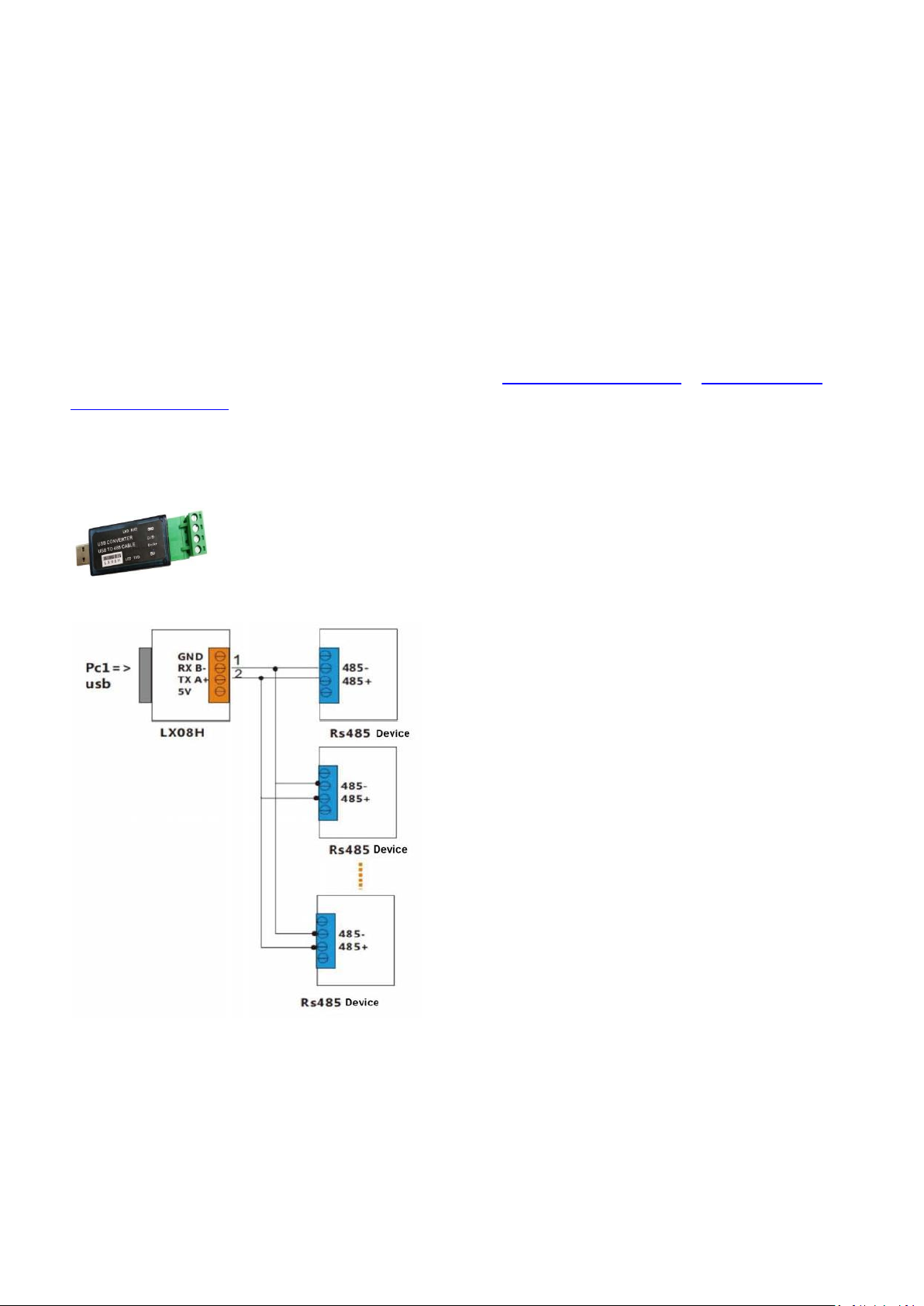
To connect a PC or Android device to a CaMate illuminator via the RS485 interface, an USB‐to‐RS485
converter should be used. The converter is separately purchased. An example is shown below:
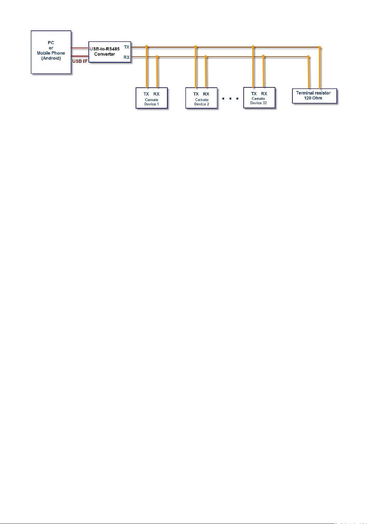
An exemplary connection should look like this:
Page 5
5
NOTES: If termination is required, a resistor value of 120Ω or greater should be used, and no more than
2 termination resistors should be used, one at each end of the RS485 transmission line.
Page 6
6
2. Windows Application Software
After the device driver for the USB-to-RS485 converter is installed (refer to the installation guide that
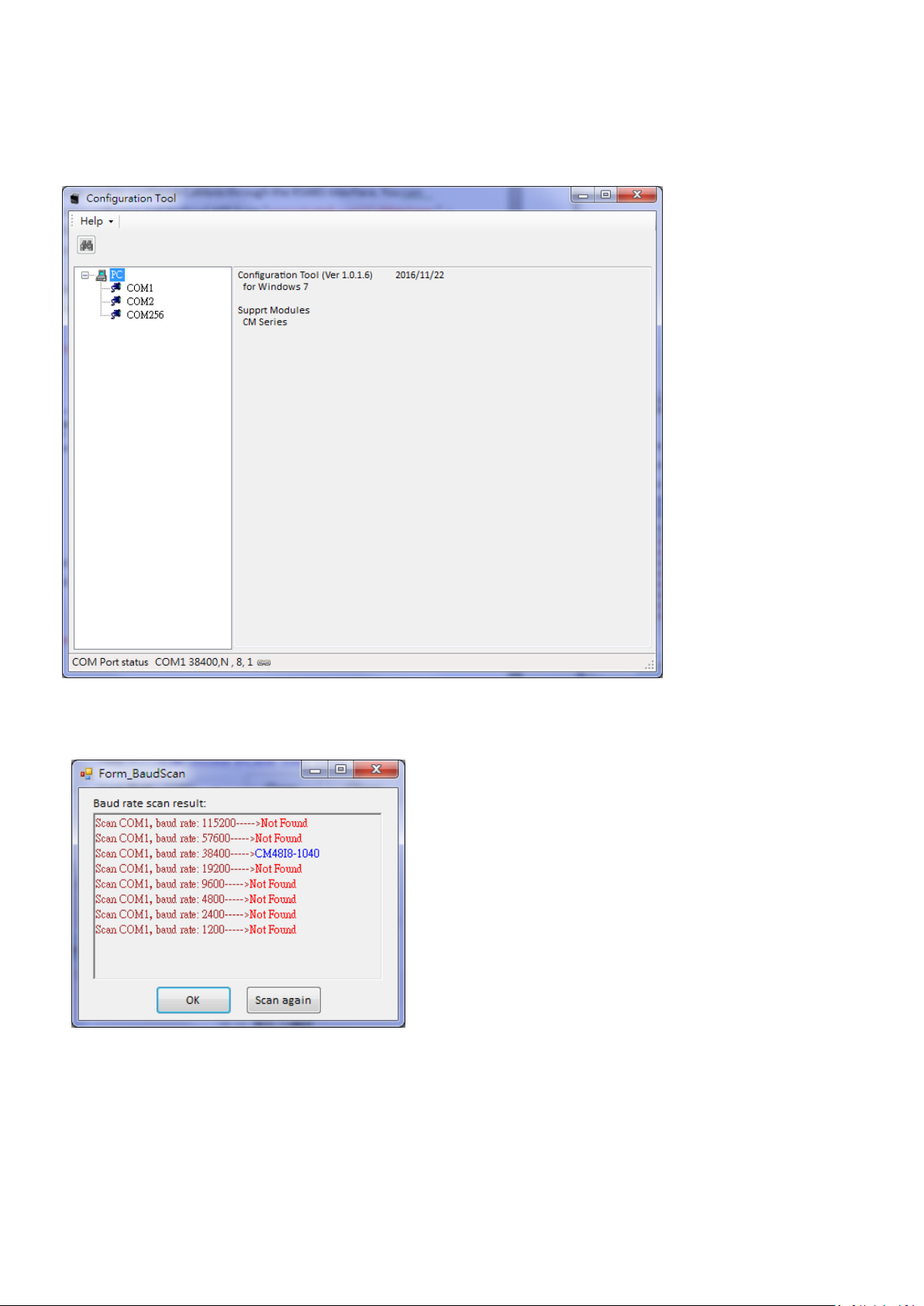
comes with the USB-to-RS485 converter), execute the EXIR_ConfigurationTool.exe application software.
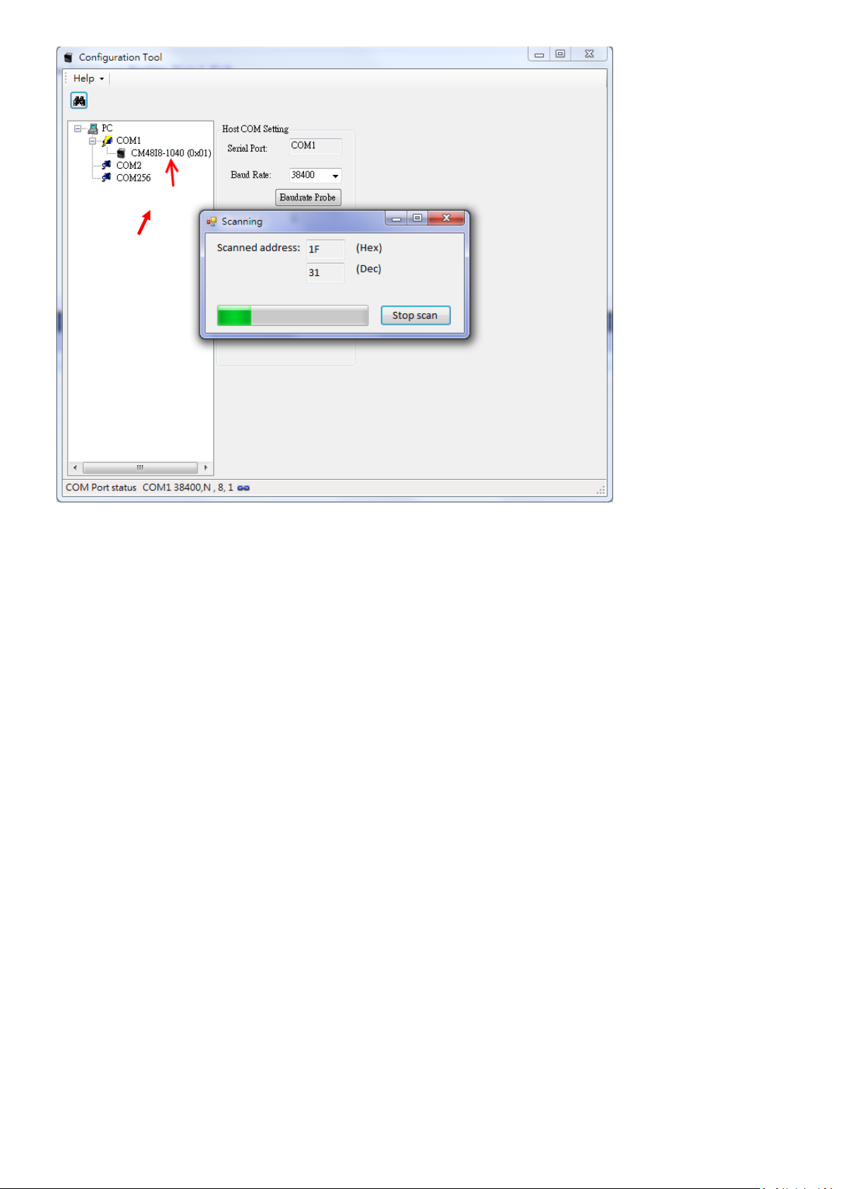
1. First select the correct COM port that is connected to CaMate.
If you are not sure of the baudrate of CaMate, (default is 38,400), you can use the Baudrate probe icon to
search for the correct baudrate.
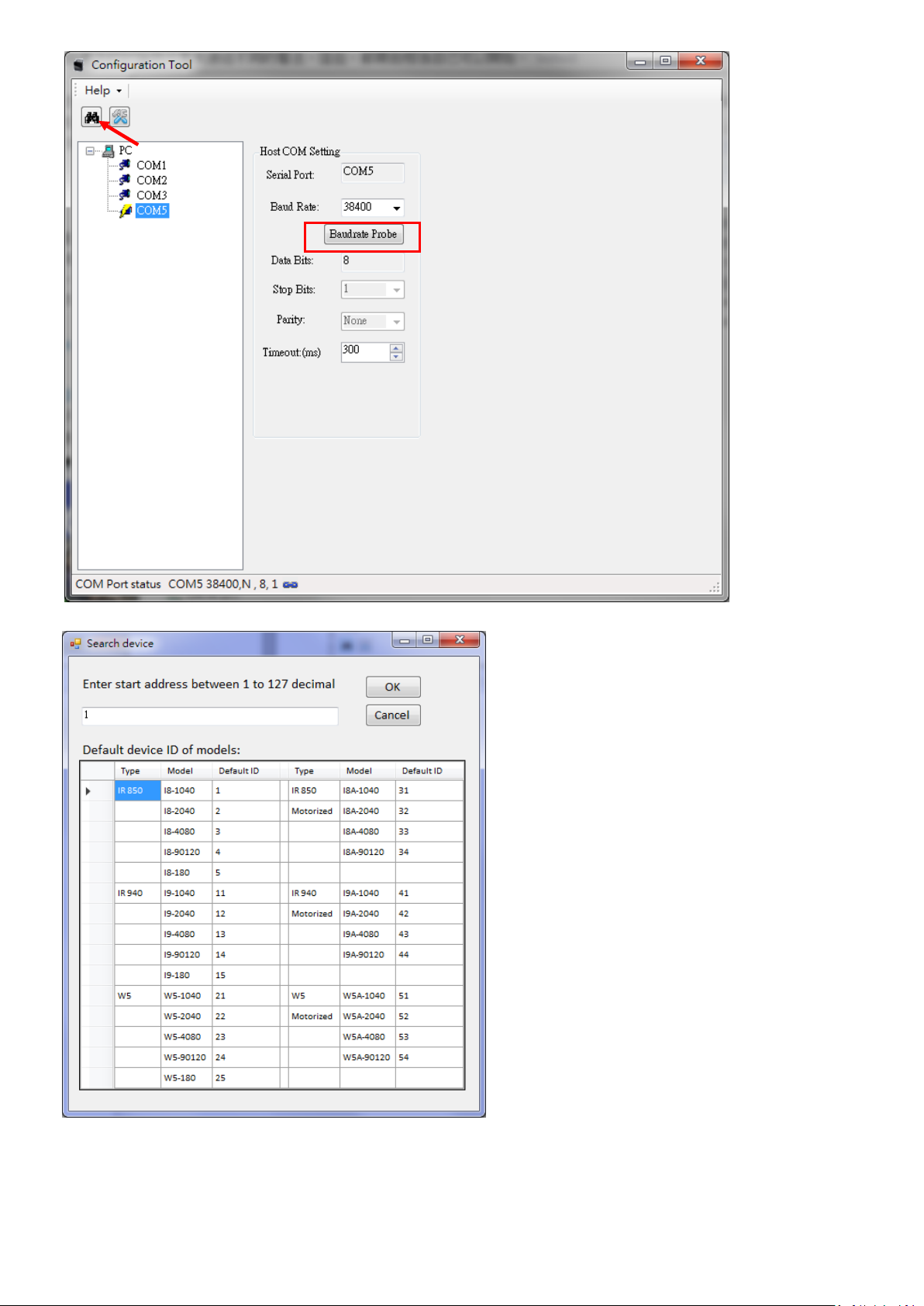
2. Then, configure the correct baudrate and click the Find icon. A search device window will prompt to ask
for a start Device ID number. Default is 1. Unless a change to the device ID of your CaMate was made,
otherwise, press OK to start finding from device ID 1. You can press the Stop scan button any time once
your CaMate is found.
Page 7
7
Page 8
8
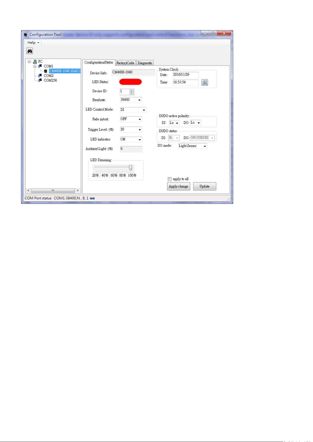
The CaMate illuminator thus found will be listed under the selected COM port. Select the CaMate you
want to configure and/or control, and the Configuration/Status page will display.
Page 9
9
2.1 Configuration/Status Page
2.1.1 Apply change
The Apply change button lets the configuration values take effect. CaMate configuration values will
not be saved until you click the Apply change button.
2.1.2 Update
The Update button is to used to query the CaMate configuration to display on the software. To
ensure the software is displaying the latest information from CaMate, you should use Update
button before you start to configure.
2.1.3 Device Info
Device Info indicates the CaMate model name, e.g., CM48I8‐1040.
2.1.4 LED Status
LED Status depicts the current ON/OFF state of LED. Red means OFF, and Green means ON.
2.1.5 Device ID
Each device comes with a unique Device ID when multiple CaMate devices are present on the RS485
bus. The Device ID ranges from 0 to 127. Make sure you configure different IDs for CaMate devices
bearing the same model name. There are a total of 128 device IDs, i.e. 0 ~ 127. A special Master
Page 10
Device ID 80h (128) can be used to configure any device no matter what the device ID of devices is
Model
Device ID
Remarks
IR 850
CM48I8-1040
1 CM80I8-1040
1
CM48I8-2040
2
CM80I8-2040
2 CM48I8-4080
3
CM80I8-4080
3
CM48I8-90120
4 CM80I8-90120
4
CM48I8-180
5
IR 940
CM48I9-1040
11 CM48I9-2040
12
CM48I9-4080
13
CM48I9-90120
14
W5
CM48W5-1040
21
CM48W5-2040
22
CM48W5-4080
23 CM48W5-90120
24
Model
Device ID
Remarks
IR 850
motorized
CA48I8-1040
31 CA80I8-1040
31
CA48I8-2040
32
CA80I8-2040
32 CA48I8-4080
33
CA80I8-4080
33
CA48I8-90120
34 CA80I8-90120
34
IR 940
motorized
CA48I9-1040
41
CA48I9-2040
42 CA48I9-4080
43
CA48I9-90120
44
W5
motorized
CA48W5-1040
51 CA48W5-2040
52
CA48W5-4080
53
CA48W5-90120
54
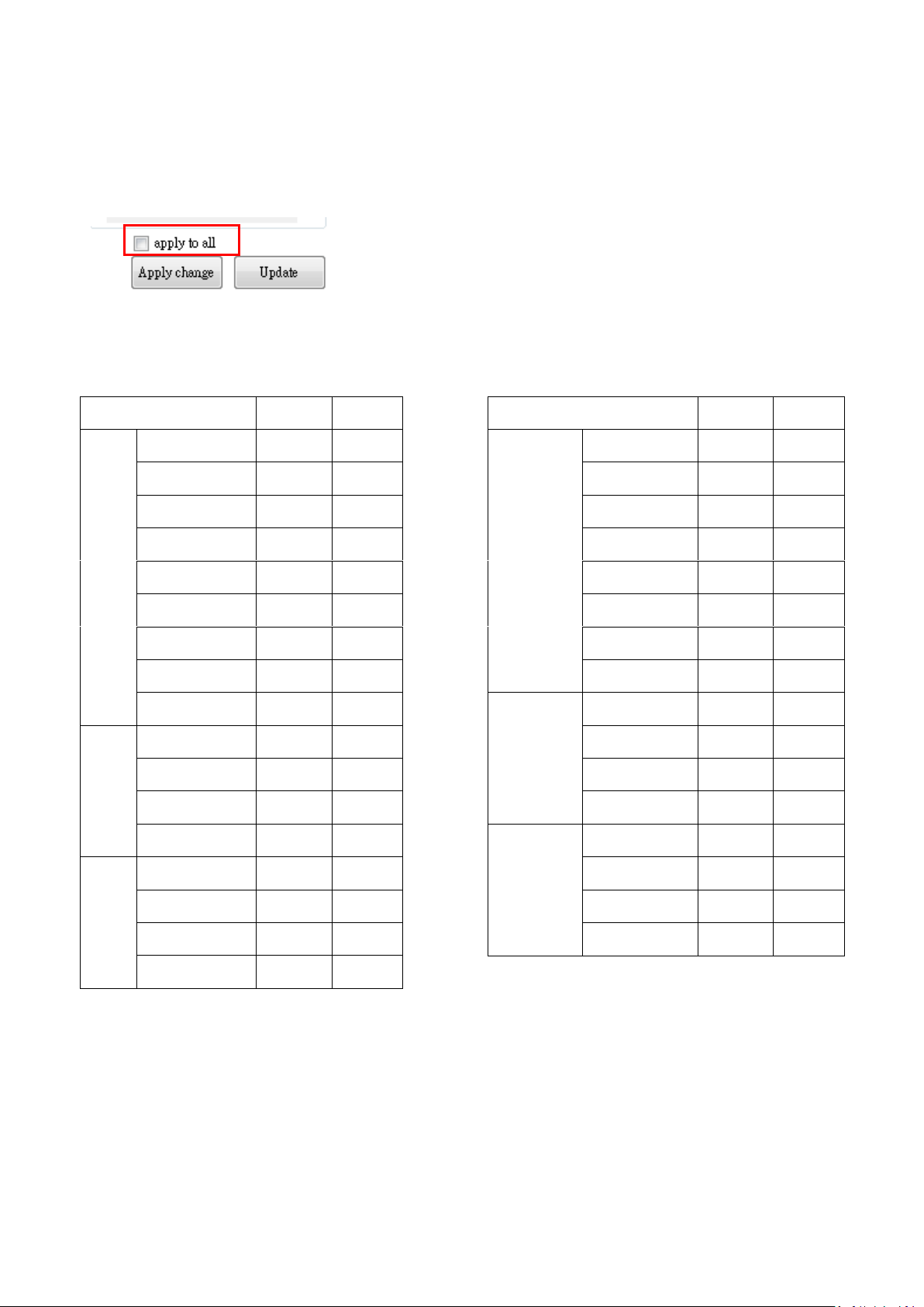
(the Master device ID only supports configuration and control functions, but not query ). The
Master Device ID can be used to configure multiple devices connected together with the same
configuration profile. If the apply to all checkbox is selected, the software will use the Master
device ID to proceed with configuration.
Default Device ID of models
10
Page 11
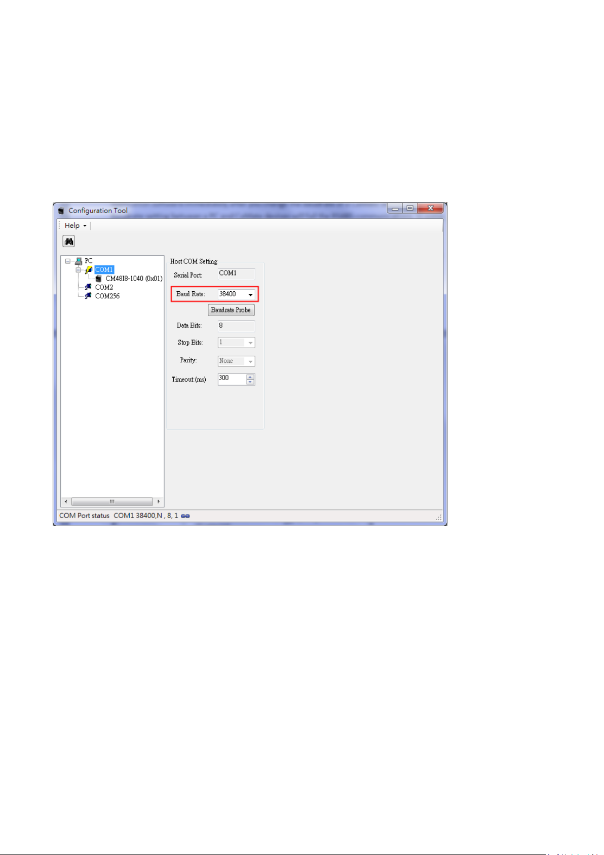
2.2 Baudrate
Baudrate sets the communication speed of CaMate devices on the RS485 interface. The Max. rate is
115,200, and the min. is 1,200. The default baudrate is 38,400. Remember to change the baudrate of
application software immediately after you change the baudrate of a CaMate device. Mismatched
Baudrate setting between a PC and CaMate devices will fail the RS485 communications. In some
computers, the max. baudrate may only reach 38,400.
It is recommended not to change the baudrate of CaMate devices because once the baudrate is changed
and forgotten, the only way is to run the PC software is to probe the baudrate.
2.3 LED Control Mode
There are 4 control modes for the illuminator LEDs: DI mode, Direct mode, Timer mode, and Light sensor
mode.
2.3.1 DI mode
In the DI mode, the system default, the LED ON/OFF is controlled via a DI signal. The associated
configuration is DI/DO active polarity, which defines the activation polarity of DI, e.g. low voltage or
high voltage. The DI/DO status shows the current state of DI and DO signal. The DI mode applies when
the application prefers a control signal from an external device, e.g., a network camera or a PIR
detector.
11
Page 12
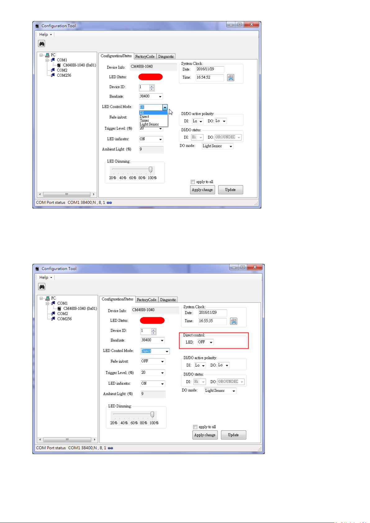
2.3.2 Direct mode
In the Direct control mode, the IR LED is controlled by the commands issued through the RS485
interface.
12
Page 13
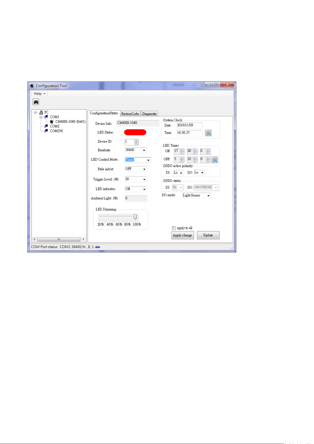
2.3.3 Timer mode
There is an embedded system clcok on CaMate devices. The Timer mode allows the configuration of
periodical ON/OFF time to control LED automatically. However, since there is no battery in CaMate, the
system Clock will reset to default setting when powered down. (If you need to implement a battery to
sustain the system clock during power-off, please contact your sales representative for customization
service)
2.3.4 Light sensor mode
In the Light sensor mode, the LED is directly controlled by the light sensor status. If the Ambient Light is
lower than the Trigger Level, LED turns ON. If higher than the Trigger level, the LED turns OFF.
2.4 Fade in/out
The Fade in/out control defines the LED ON/OFF behavior. If the Fade in/out function is disabled, the LED
is turned ON or OFF immediately. When the Fade in/out is set to FAST, the LED fades in or out in 1 second,
and 3 seconds if set to SLOW. Fade in/out can avoid sudden LED ON/OFF, which may cause the occurrence
of over-exposure or under-exposure on camera image. The sudden ON/OFF will also cause discomfort for
human eyes when using the visible light CaMate, such as the w5 series.
13
Page 14
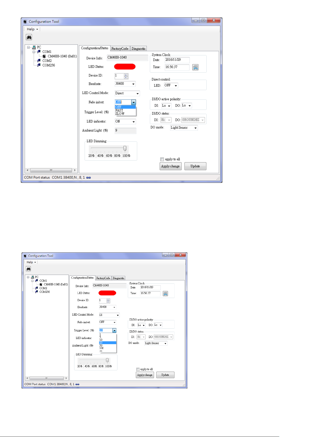
2.5 Trigger Level
Trigger Level defines the ambient Lux threshold for the embedded light sensor. There are 7 threshold
levels. 20 % is the default value. "" represents the infinite value, which means the light sensor detection
is always active. When the ambient light falls under the triggering threshold, the LEDs enter the active
state, and will become inactive state when the light level is 10 % above the threshold, e.g., when the
detected level is 30%.
14
Page 15

2.6 LED indicator
LED indicator activates or deactivates the information status LED, i.e. red and green LEDs (not the IR
illumination LEDs). Because of opaque front cover in the IR models, I8 and I9, the LED indicators only can
be seen in the non-IR CaMate products, i.e. w5. Below are the definitions of LED indicators:
Red LED constant ON means normal operation, OFF means system is not working.
Red LED flashes every 1 second means IR LEDs are overheated, flashes every 3 seconds means
LED voltage is out of range.
Green LED flashes means the device received and executing commands.
If both red and green LEDs flash simultaneously, the device upgrading its firmware.
2.7 Ambient Light
Ambient Light reports the current ambient lighting level. The ambient light level is polled every 10
seconds. The light sensor detection control may have a max. of 10 seconds delay when the ambient light
level changes.
2.8 LED Light Level
LED Light Level controls the strength of LED lighting from 100% (default setting, max. power consumption)
to 20% when the LED is ON.
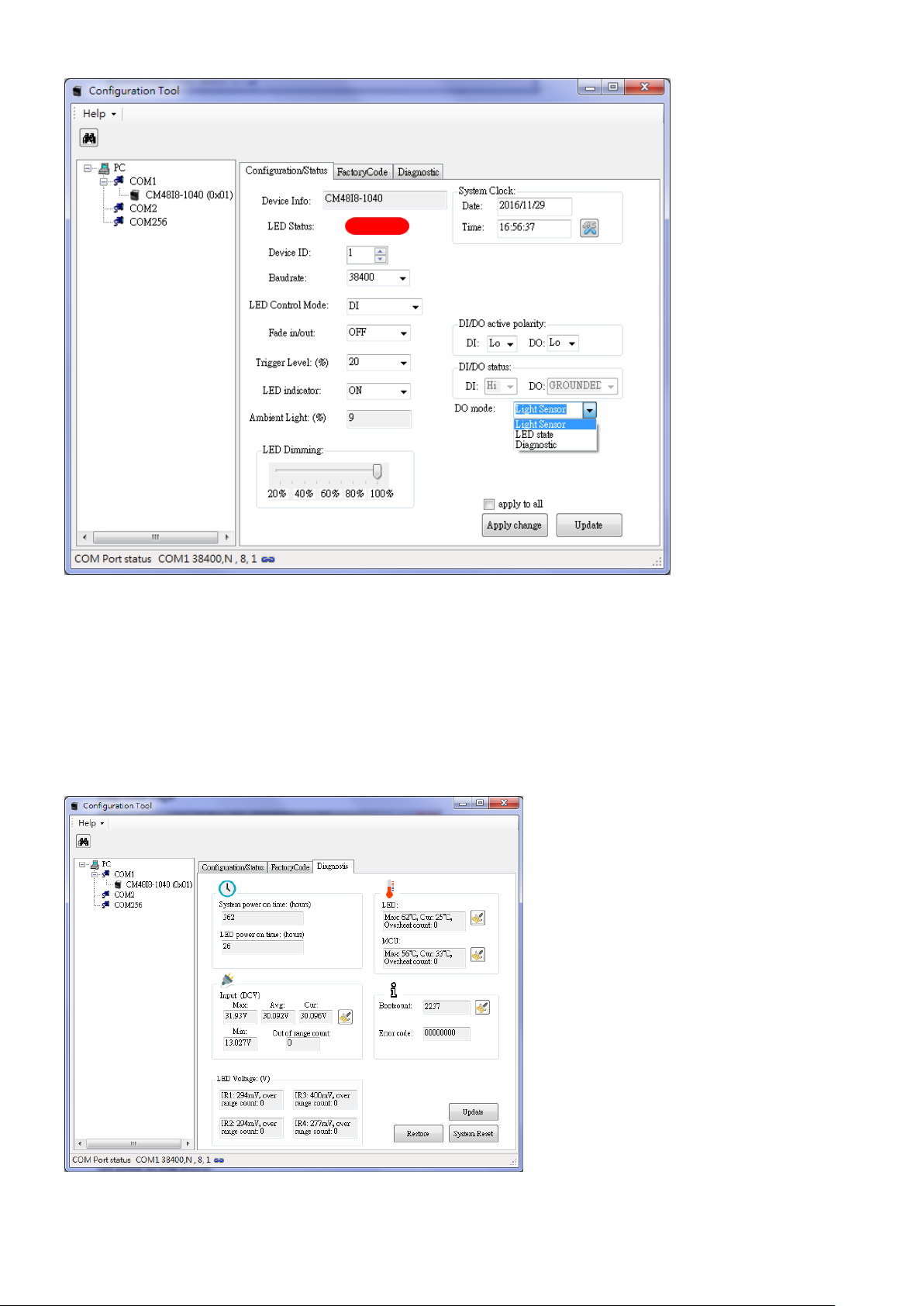
2.9 DO Mode
The DO mode defines the function of DO pin. The DO signal can be used to report three conditions:
Detected Light Level, LED state, or Diagnostic mode. The DO pin signal follows the DO active polarity
setting.
2.9.1 DO light sensor mode
In the default Light sensor mode, the DO pin outputs the light sensor detection result as the "bright"
state (ambient lighting higher than the Triggering level) or the "dark" state (ambient light lower than
the Triggering level). If the application requires CaMate to report Day/Night mode to other devices, e.g.,
the network camera, the DO mode should be configured to the Light sensor mode.
2.9.2 DO LED state mode
In the LED state mode, the DO pin outputs the LED ON/OFF state. If a CaMate is operating in the Direct
or Light sensor LED control mode, other devices can acknowledge the CaMate's LED ON/OFF status via
the DO connection.
2.9.3 DO Diagnostic mode
In the Diagnostic mode, the DO pin outputs the LED health status. Abnormal conditions may include:
LEDs overheated or LED voltage out of range. The Diagnostic mode can be used for maintenance
purpose.
15
Page 16
2.10 Angle Level (Only available for the motorized version of CaMate, e.g.
CA48I8-1040)
Angle level is used to adjust the beam angle of CaMate, and thus adjust the effective IR illumination
range.
2.11 Diagnostic Page
16
Page 17

In the diagnostics page, you can find important system operating information.
2.11.1 System power on time (hours)
System power on time records total the accumulated number of operating hours.
2.11.2 LED power on time (hours)
LED power on time as the total LED ON hours.
2.11.3 Inputs
The Input state reports the input voltage of power supply to CaMate. It records the Max. and Min.
voltage ever recorded, the average voltage during operation, and the current voltage reading. The Out
of range count records the event when the input voltage is under DC12V -10% (DC10.8V) or over the
AC24V+10% (AC26.4V).
2.11.4 LED Voltage
The LED voltage reports the health condition for LED strings, as there are 4 LED strings in CaMate. The
normal LED ON voltage should fall between 400mV and 1200mV. The Over range count records the
event when the detected LED voltage is over 1200mV. Once the LED voltage is over range, the LED is
probably damaged. The 4 LED strings work independently.
2.11.5 LED Temperature
The LED temperature records the Max. temperature of LEDs ever happened, the current temperature,
and the count of overheating events.
CaMate supports the automatic overheat protection when IR LED is overheated, i.e., over 95C (203F),
by automatically reducing the current to maintain the LED working in a safe temperature range and to
ensure the device reliability and longevity.
2.11.6 MCU Temperature
MCU temperature records the Max. temperature ever happened to MCU, current temperature reading,
and the count of overheating events.
2.11.7 Boot count
How many times the device is power on and off. It can be used to check if power losses have occurred
in the operation history.
2.11.8 Error code
The Error code is used for diagnostics purposes. You can report the error code to your technical support
for help if the device is out of order.
17
Page 18

2.12 Firmware Upgrade
CaMate's firmware can be upgraded through the RS485 interface. Access the firmware upgrade function
in the Help menu.
Select Firmware Upgrade , the Firmware Upgrade window will prompt.
1. Select the correct COM port, Baudrate, and Device ID, then click the OPEN COM button. When a
CaMate is connected, current firmware version and checksum will be read and shown.
18
Page 19

If the software cannot connect to a CaMate, a timeout warning displays. Please check if the COM port
and/or baudrate settings are correct, or the wire connection is correctly made.
2. Load CaMate firmware binary code by clicking the Load button, and select the correct binary file. The
new firmware version and checksum will display after loading.
You can find the firmware binary file at www.vivotek.com or contact your sales representative.
3. Click FW Update and confirm the upload, firmware upgrade will then start. Please do not turn off the
power to CaMate untill the upgrade is completed.
19
Page 20

20
Page 21

2.13 FactoryCode Page
The FactoryCode page records manufacturing information of the device. Generally, the code is used for
manufacturing.
Model ID
Model ID represents the model of CaMate.
FW Rev/Chks
Firmware revision and checksum of the code.
Max Current
Allowed max. LED current. It depends on hardware circuitry design.
Default Current
Default LED current configuration.
Lens angle
Optical Lens used in CaMate, e.g., 10 ~ 40.
Factory Date
Manufacturing date.
Factory Time
Manufacturing time.
21
Page 22

3. Android APP
After you install CaMateTool.apk in your Android device, the app will automatically launch upon
USB-to- RS485 converter connection. If not, tap the CaMate icon on the screen to launch.
When CaMateTool screen appears, the app enables RS-485 communication using the default baud rate
- 38,400 bps. The default device ID is 1. You can select a new one by touching the device ID value using a
drop-down menu with all other available values. Then, click on the Update button, the app will query
configuration status and display them on screen.
22
Page 23

Device configuration
After the configuration value is changed, click the Apply changes button for the configuration changes to
take effect. For the configuration details, please refer to the description in Windows Application Software
- Configuration/Status Page.
Device diagnostic information
For the diagnostic information, please refer to the description in Windows Application Software Diagnostic Page.
23
Page 24

Device list (baudrate scan and device search)
If you are not sure of the baudrate or device ID of CaMate, you can scroll down on the screen, click the
Press to Start button to search for correct baudrate and device ID. You can click Press to Stop button to
stop scanning anytime once your CaMate is found.
24
Page 25

4. Remote Controller
Unlock
By default, the CaMate IR remote control is disabled. To enable the control function, the unlock
button must be pressed continuously for at least 2 seconds. After being idle for 5 minutes, it
automatically enters the lock mode to disable IR remote control function.
LED on/off
The button is a toggle switch to turn LEDs on/off.
LED status
25
Page 26

The button is a toggle switch to turn status LED indicators on/off. Because of the opaque front cover
in the IR version, I8 and I9, the LED indicators only can be seen in the non‐IR CaMate products, i.e. w5.
Light sensor sensitivity
There are three pre‐defined levels to configure the light sensor threshold values.
Turn LED on when the ambient light is under 50 % and turn off when the ambient light is above 60%.
Turn LED on when ambient light is under 20 % and turn off when the ambient light is above 30 %.
Turn LED on when ambient light is under 10 % and turn off when the ambient light is above 20 %.
LED dimming
There are four pre‐defined levels to configure the strength of LED lighting.
100%
75%
50 %
25%
The fine‐tune button set the strength of LED lighting from 100% to 20%.
26
Page 27

Angle of illuminator
(Only available for the motorized version of CaMate, e.g. CM48I8A‐1040). The Angle level is used to
adjust the beam angle of CaMate for variable effective illumination distances.
Adjusts angle to tele
Adjusts angle to 66%
Adjusts angle to 33%
Adjusts angle to wide
Adjusts angle to tele (fine‐tune)
Adjusts angle to wide (fine-tune)
27
Page 28

5. Appendix
5.1 Appendix A: Pelco-D set of CaMate
Standard Commands
The Cmd2 of standard commands is always even. Responses are suppressed for standard commands
because some controllers output many repeated commands in rapid succession without sufficiently
delaying for a response to be sent between commands.
Extended Commands
The Cmd2 of Extended commands is always odd.
5.1.0 Use Windows Application Software to get commands
1. First select the command generator.
28
Page 29

2. Then, select Model information and the commands you want. The correspond Pelco-D command will
shown on the right
3. Copy and paste to command line on web page
29
Page 30

5.1.1 Soft reset (0x0F)
Byte number
1 2 3 4 5 6 7
Byte Definition
Sync
Addr
Cmd1
Cmd2
Data1
Data2
ChkSum
Set LED control
mode
0xFF
0x01
0x00
0x0F
0x00
0x00
--
Byte number
1 2 3
4
Byte Definition
Sync
Addr
Faults
ChkSum
General Response
0xFF
0x01
--
--
Byte number
1 2 3 4 5 6 7
Byte Definition
Sync
Addr
Cmd1
Cmd2
Data1
Data2
ChkSum
Set LED control
mode
0xFF
0x01
0x00
0x29
0x00
0x00
--
Byte number
1 2 3
4
Byte Definition
Sync
Addr
Faults
ChkSum
General Response
0xFF
0x01
--
--
Byte number
1 2 3 4 5 6 7
Byte Definition
Sync
Addr
Cmd1
Cmd2
Data1
Data2
ChkSum
Set LED control
mode
0xFF
0x01
0x00
0x4F
Zoom %
MSB
Zoom %
LSB
--
Byte number
1 2 3
4
Byte Definition
Sync
Addr
Faults
ChkSum
General Response
0xFF
0x01
--
--
Byte number
1 2 3 4 5 6 7
Byte Definition
Sync
Addr
Cmd1
Cmd2
Data1
Data2
ChkSum
Query LED control
mode
0xFF
0x01
0x00
0x55
0x00
0x00
--
Response Format:
5.1.2 Reset to default (0x29)
Response Format:
5.1.3 Set zoom position (0x4F)
The command set CaMate’s zoom position to an absolute value from 0-100%. The position is sent as a
16-bit value in Data1 and Data2, scaled by 65535(0xFFFF).
Response Format:
5.1.4 Get zoom position (0x55)
This command returns CaMate’s current zoom position.
Command format:
30
Page 31

Response Format:
Byte number
1 2 3 4 5 6 7
Byte Definition
Sync
Addr
Resp1
Resp2
Data1
Data2
ChkSum
Extended Response
0xFF
0x01
0x00
0x5D
Zoom %
MSB
Zoom %
LSB
--
Byte number
1 2 3 4 5 6 7
Byte Definition
Sync
Addr
Cmd1
Cmd2
Data1
Data2
ChkSum
Set LED control
mode
0xFF
0x01
0x00
0x67
0x00
Baud rate
--
Byte number
1 2 3
4
Byte Definition
Sync
Addr
Faults
ChkSum
General Response
0xFF
0x01
--
--
Byte number
1 2 3 4 5 6 7
Byte Definition
Sync
Addr
Cmd1
Cmd2
Data1
Data2
ChkSum
Query LED control
mode
0xFF
0x01
0x00
0x6B
0x00
0x00
--
Byte number
1 2 3 4 5 6 7
Byte Definition
Sync
Addr
Resp1
Resp2
Data1
Data2
ChkSum
Extended Response
0xFF
0x01
Model ID
byte3
Model ID
byte2
Model ID
byte1
Model ID
byte0
--
5.1.5 Set Baud rate (0x67)
The command will change CaMate’s baud rate.
Response Format:
0x00 Baud rate: 1200 bps 0x04 Baud rate: 19200 bps
0x01 Baud rate: 2400 bps 0x05 Baud rate: 38400 bps
0x02 Baud rate: 4800 bps 0x06 Baud rate: 57600 bps
0x03 Baud rate: 9600 bps 0x07 Baud rate: 115200 bps
5.1.6 Query device type (0x6B)
This command returns CaMate’s model ID.
Command format:
Response Format:
5.1.7 Set/Read Configuration information (0x6D)
This command sets/returns CaMate’s LED control mode, DIO’s polarity, DO mode, device ID address, LED
status, LED indicator on/off control.
31
Page 32

Byte number
1 2 3 4 5 6 7
Byte Definition
Sync
Addr
Cmd1
Cmd2
Data1
Data2
ChkSum
Query LED control
mode
0xFF
0x01
0x02
0x6D
0x00
0x00
--
Byte number
1 2 3 4 5 6 7
Byte Definition
Sync
Addr
Resp1
Resp2
Data1
Data2
ChkSum
Extended Response
0xFF
0x01
0x00
0x00
0x00
LED ctrl
mode
--
Byte number
1 2 3 4 5 6 7
Byte Definition
Sync
Addr
Cmd1
Cmd2
Data1
Data2
ChkSum
Set LED control
mode
0xFF
0x01
0x82
0x6D
0x00
LED ctrl
mode
--
Byte number
1 2 3
4
Byte Definition
Sync
Addr
Faults
ChkSum
General Response
0xFF
0x01
--
--
Byte number
1 2 3 4 5 6 7
Byte Definition
Sync
Addr
Cmd1
Cmd2
Data1
Data2
ChkSum
Query Fade in/out
0xFF
0x01
0x04
0x6D
0x00
0x00
--
5.1.7.1 LED control mode
There are 4 control modes of LED, i.e. DI, Direct, Timer, and Light sensor.
DI mode (default): in this mode, LED on/off is controlled by DI signal
Direct mode: LED on/off is controlled by command through RS485
Timer mode: set the periodical on/off time to control LED automatically
Light sensor mode: LED is controlled by light sensor status. If ambient light is lower than threshold level,
LED turns on, else off.
Command format: Get
Response Format:
LED ctrl mode: (0)DI/(1)Direct/(2)Timer/(3) Light Sensor
Command format: Set
Response Format:
5.1.7.2 Fade in/out control
Fade in/out control the on/off behavior of LED, to avoid sudden LED on/off at which may cause camera
over-exposure or under-exposure.
Off: the LED is on or off immediately.
Fast: the LED fades in or out in 1 second.
Slow: the LED fades in or out in 3 seconds.
Command format: Get
32
Page 33

Response Format:
Byte number
1 2 3 4 5 6 7
Byte Definition
Sync
Addr
Resp1
Resp2
Data1
Data2
ChkSum
Extended Response
0xFF
0x01
0x00
0x00
0x00
LED fade
in/out
--
Byte number
1 2 3 4 5 6 7
Byte Definition
Sync
Addr
Cmd1
Cmd2
Data1
Data2
ChkSum
Set Fade in/out
0xFF
0x01
0x84
0x6D
0x00
LED fade
in/out
--
Byte number
1 2 3
4
Byte Definition
Sync
Addr
Faults
ChkSum
General Response
0xFF
0x01
--
--
Byte number
1 2 3 4 5 6 7
Byte Definition
Sync
Addr
Cmd1
Cmd2
Data1
Data2
ChkSum
Query DIO’s polarity
0xFF
0x01
0x06
0x6D
0x00
0x00
--
Byte number
1 2 3 4 5 6 7
Byte Definition
Sync
Addr
Resp1
Resp2
Data1
Data2
ChkSum
Extended Response
0xFF
0x01
0x00
DI’s
polarity
0x00
DO’s
polarity
--
Byte number
1 2 3 4 5 6 7
Byte Definition
Sync
Addr
Cmd1
Cmd2
Data1
Data2
ChkSum
Set DIO’s polarity
0xFF
0x01
0x86
0x6D
DI’s
polarity
DO’s
polarity
--
Byte number
1 2 3
4
Byte Definition
Sync
Addr
Faults
ChkSum
General Response
0xFF
0x01
--
--
Fade in/out: (0) off / (1) Fast/ (2) Slow
Command format: Set
Response Format:
5.1.7.3 DI/DO active polarity
Command format: Get
Response Format:
DIO's active polarity: (0)Lo/(1)Hi
Command format: Set
Response Format:
5.1.7.4 DO mode
DO mode defines the function of DO pin, there are three modes.
33
Page 34

Light sensor: DO pin outputs the light sensor detection result.
Byte number
1 2 3 4 5 6 7
Byte Definition
Sync
Addr
Cmd1
Cmd2
Data1
Data2
ChkSum
Query DO mode
0xFF
0x01
0x08
0x6D
0x00
0x00
--
Byte number
1 2 3 4 5 6 7
Byte Definition
Sync
Addr
Resp1
Resp2
Data1
Data2
ChkSum
Extended Response
0xFF
0x01
0x00
0x00
0x00
DO mode
--
Byte number
1 2 3 4 5 6 7
Byte Definition
Sync
Addr
Cmd1
Cmd2
Data1
Data2
ChkSum
Set DO mode
0xFF
0x01
0x88
0x6D
0x00
DO mode
--
Byte number
1 2 3
4
Byte Definition
Sync
Addr
Faults
ChkSum
General Response
0xFF
0x01
--
--
Byte number
1 2 3 4 5 6 7
Byte Definition
Sync
Addr
Cmd1
Cmd2
Data1
Data2
ChkSum
Query LED on/off
status
0xFF
0x01
0x0A
0x6D
0x00
0x00
--
Byte number
1 2 3 4 5 6 7
Byte Definition
Sync
Addr
Resp1
Resp2
Data1
Data2
ChkSum
Extended Response
0xFF
0x01
0x00
0x00
0x00
LED
on/off
--
Byte number
1 2 3 4 5 6 7
Byte Definition
Sync
Addr
Cmd1
Cmd2
Data1
Data2
ChkSum
Set LED on/off
status
0xFF
0x01
0x8A
0x6D
0x00
LED
on/off
--
LED state: DO pin outputs the LED on/off state.
Diagnostic: DO pin outputs the health condition of LED for maintenance purpose.
Command format: Get
Response Format:
DO mode: (0) Light sensor state/ (1) LED state/ (2) Diagnostic
Command format: Set
Response Format:
5.7.1.5 LED on/off
When LED control mode is in direct mode, this command set CaMate to turn on or off.
Command format: Get
Response Format:
LED on/off state: (0) off/ (1) on
Command format: Set
34
Page 35

Response Format:
Byte number
1 2 3
4
Byte Definition
Sync
Addr
Faults
ChkSum
General Response
0xFF
0x01
--
--
Byte number
1 2 3 4 5 6 7
Byte Definition
Sync
Addr
Cmd1
Cmd2
Data1
Data2
ChkSum
Query indicator
on/off
0xFF
0x01
0x0C
0x6D
0x00
0x00
--
Byte number
1 2 3 4 5 6 7
Byte Definition
Sync
Addr
Resp1
Resp2
Data1
Data2
ChkSum
Extended Response
0xFF
0x01
0x00
0x00
0x00
Indicator
on/off
--
Byte number
1 2 3 4 5 6 7
Byte Definition
Sync
Addr
Cmd1
Cmd2
Data1
Data2
ChkSum
Set indicator on/off
0xFF
0x01
0x8C
0x6D
0x00
indicator
on/off
--
Byte number
1 2 3
4
Byte Definition
Sync
Addr
Faults
ChkSum
General Response
0xFF
0x01
--
--
Read-only if LED control is not in direct mode.
5.1.7.6 Indicator on/off
LED indicators activate or deactivate the information status LED. If indicator is on, the meanings of LED is
as below.
If red LED keeps ON means normal, keeps OFF means system is not working.
If red LED flashes every 1 second means LED is overheat, flashes every 3 seconds means LED
voltage is out of range.
Green LED flashes means the device received and executed commands.
If both red and green LEDs flash simultaneously, the device is in firmware upgrade mode.
Command format: Get
Response Format:
LED on/off state: (0) off/ (1) on
Command format: Set
Response Format:
35
Page 36

5.1.7.7 Device ID address
Byte number
1 2 3 4 5 6 7
Byte Definition
Sync
Addr
Cmd1
Cmd2
Data1
Data2
ChkSum
Query device ID
address
0xFF
0x01
0x0E
0x6D
0x00
0x00
--
Byte number
1 2 3 4 5 6 7
Byte Definition
Sync
Addr
Resp1
Resp2
Data1
Data2
ChkSum
Extended Response
0xFF
0x01
0x00
0x00
0x00
Device ID
address
--
Byte number
1 2 3 4 5 6 7
Byte Definition
Sync
Addr
Cmd1
Cmd2
Data1
Data2
ChkSum
Set device ID
address
0xFF
0x01
0x8E
0x6D
0x00
Device ID
address
--
Byte number
1 2 3
4
Byte Definition
Sync
Addr
Faults
ChkSum
General Response
0xFF
0x01
--
--
Byte number
1 2 3 4 5 6 7
Byte Definition
Sync
Addr
Cmd1
Cmd2
Data1
Data2
ChkSum
Query Clock time
0xFF
0x01
0x14
0x6D
0x00
0x00
--
Byte number
1 2 3 4 5 6 7
Byte Definition
Sync
Addr
Resp1
Resp2
Data1
Data2
ChkSum
Extended Response
0xFF
0x01
0x00
Hour
Minute
Second
--
Byte number
1 2 3 4 5 6 7
Byte Definition
Sync
Addr
Cmd1
Cmd2
Data1
Data2
ChkSum
Set Clock time -
hour
0xFF
0x01
0x94
0x6D
0x00
Hour
--
Byte number
1 2 3 4 5 6 7
Command format: Get
Response Format:
Device ID address: 1~127
Command format: Set
Response Format:
5.1.7.8 Clock time
This command returns the time of clock in MCU. Due to no battery is installed in CaMate, the clock data
will reset if power is off.
Command format: Get
Response Format:
Command format: Set
36
Page 37

Byte Definition
Sync
Addr
Cmd1
Cmd2
Data1
Data2
ChkSum
Set Clock time –
min/sec
0xFF
0x01
0x96
0x6D
Minute
Second
--
Response Format:
Byte number
1 2 3
4
Byte Definition
Sync
Addr
Faults
ChkSum
General Response
0xFF
0x01
--
--
Byte number
1 2 3 4 5 6 7
Byte Definition
Sync
Addr
Cmd1
Cmd2
Data1
Data2
ChkSum
Query timer LED on
0xFF
0x01
0x18
0x6D
0x00
0x00
--
Byte number
1 2 3 4 5 6 7
Byte Definition
Sync
Addr
Resp1
Resp2
Data1
Data2
ChkSum
Extended Response
0xFF
0x01
0x00
Hour
Minute
Second
--
Byte number
1 2 3 4 5 6 7
Byte Definition
Sync
Addr
Cmd1
Cmd2
Data1
Data2
ChkSum
Set timer LED on -
hour
0xFF
0x01
0x98
0x6D
0x00
Hour
--
Byte number
1 2 3 4 5 6 7
Byte Definition
Sync
Addr
Cmd1
Cmd2
Data1
Data2
ChkSum
Set timer LED on –
min/sec
0xFF
0x01
0x9A
0x6D
Minute
Second
--
Byte number
1 2 3
4
Byte Definition
Sync
Addr
Faults
ChkSum
General Response
0xFF
0x01
--
--
Byte number
1 2 3 4 5 6 7
Byte Definition
Sync
Addr
Cmd1
Cmd2
Data1
Data2
ChkSum
Query timer LED off
0xFF
0x01
0x1C
0x6D
0x00
0x00
--
5.1.7.9 Timer LED on
These commands return or set the periodical time of LED on.
Command format: Get
Response Format:
Command format: Set
Response Format:
5.1.7.10 Timer LED off
These commands return or set the periodical time of LED off.
Command format: Get
37
Page 38

Response Format:
Byte number
1 2 3 4 5 6 7
Byte Definition
Sync
Addr
Resp1
Resp2
Data1
Data2
ChkSum
Extended Response
0xFF
0x01
0x00
Hour
Minute
Second
--
Byte number
1 2 3 4 5 6 7
Byte Definition
Sync
Addr
Cmd1
Cmd2
Data1
Data2
ChkSum
Set timer LED off -
hour
0xFF
0x01
0x9C
0x6D
0x00
Hour
--
Byte number
1 2 3 4 5 6 7
Byte Definition
Sync
Addr
Cmd1
Cmd2
Data1
Data2
ChkSum
Set timer LED off –
min/sec
0xFF
0x01
0x9E
0x6D
Minute
Second
--
Byte number
1 2 3
4
Byte Definition
Sync
Addr
Faults
ChkSum
General Response
0xFF
0x01
--
--
Byte number
1 2 3 4 5 6 7
Byte Definition
Sync
Addr
Cmd1
Cmd2
Data1
Data2
ChkSum
Query DIO status
0xFF
0x01
0x20
0x6D
0x00
0x00
--
Byte number
1 2 3 4 5 6 7
Byte Definition
Sync
Addr
Resp1
Resp2
Data1
Data2
ChkSum
Extended Response
0xFF
0x01
0x00
0x24
DI state
DO state
--
Byte number
1 2 3 4 5 6 7
Byte Definition
Sync
Addr
Cmd1
Cmd2
Data1
Data2
ChkSum
Query ambient
hysteresis/oversample
0xFF
0x01
0x22
0x6D
0x00
0x00
--
Byte number
1 2 3 4 5 6 7
Byte Definition
Sync
Addr
Resp1
Resp2
Data1
Data2
ChkSum
Extended Response
0xFF
0x01
0x00
0x26
Hysteresis
Oversample
--
Command format: Set
Response Format:
5.1.7.11 DI/DO status
Command format: Get
Response Format:
DIO's state: (0) Lo/ (1) Hi
5.1.7.12 Hysteresis/Oversample of light sensor trigger
Command format: Get
Response Format:
38
Page 39

Command format: Set
Byte number
1 2 3 4 5 6 7
Byte Definition
Sync
Addr
Cmd1
Cmd2
Data1
Data2
ChkSum
Set ambient
hysteresis/oversample
0xFF
0x01
0xA2
0x6D
Hysteresis
Oversample
--
Byte number
1 2 3
4
Byte Definition
Sync
Addr
Faults
ChkSum
General Response
0xFF
0x01
--
--
Byte number
1 2 3 4 5 6 7
Byte Definition
Sync
Addr
Cmd1
Cmd2
Data1
Data2
ChkSum
Query temperature
0xFF
0x01
0x02
0x6F
0x00
0x00
--
Byte number
1 2 3 4 5 6 7
Byte Definition
Sync
Addr
Resp1
Resp2
Data1
Data2
ChkSum
Extended Response
0xFF
0x01
LED
Max
LED
Current
MCU
Max
MCU
Current
--
Byte number
1 2 3 4 5 6 7
Byte Definition
Sync
Addr
Cmd1
Cmd2
Data1
Data2
ChkSum
Clear temperature
0xFF
0x01
0x82
0x6F
LED Max
MCU Max
--
Byte number
1 2 3
4
Byte Definition
Sync
Addr
Faults
ChkSum
General Response
0xFF
0x01
--
--
Response Format:
5.1.8 Query Diagnostic information (0x6F)
This command returns CaMate’s temperature information, input voltage information, total system power
on time, total LED power on time, current ambient light, boot count, LED1~4 voltage, system error code,
out of range count.
5.1.8.1 Temperature of LED/MCU
Command format: Get
Response Format:
Temperature value is in 2’s complement.
Command format: Clear:
Response Format:
Set LED/MCU Max bit with 1 to clear max record
39
Page 40

5.1.8.2 Measurement of Input voltage
Byte number
1 2 3 4 5 6 7
Byte Definition
Sync
Addr
Cmd1
Cmd2
Data1
Data2
ChkSum
Query max/avg.
input voltage
0xFF
0x01
0x04
0x6F
0x00
0x00
--
Byte number
1 2 3 4 5 6 7
Byte Definition
Sync
Addr
Resp1
Resp2
Data1
Data2
ChkSum
Extended Response
0xFF
0x01
Max.
MSB
Max.
LSB
Average
MSB
Average
LSB
--
Byte number
1 2 3 4 5 6 7
Byte Definition
Sync
Addr
Cmd1
Cmd2
Data1
Data2
ChkSum
Clear max/avg. input
voltage
0xFF
0x01
0x84
0x6F
0x00
0x00
--
Byte number
1 2 3
4
Byte Definition
Sync
Addr
Faults
ChkSum
General Response
0xFF
0x01
--
--
Byte number
1 2 3 4 5 6 7
Byte Definition
Sync
Addr
Cmd1
Cmd2
Data1
Data2
ChkSum
Query current/min.
input voltage
0xFF
0x01
0x06
0x6F
0x00
0x00
--
Byte number
1 2 3 4 5 6 7
Byte Definition
Sync
Addr
Resp1
Resp2
Data1
Data2
ChkSum
Extended Response
0xFF
0x01
current
MSB
current
LSB
Min
MSB
Min
LSB
--
Byte number
1 2 3 4 5 6 7
Byte Definition
Sync
Addr
Cmd1
Cmd2
Data1
Data2
ChkSum
Query total system
power on time
0xFF
0x01
0x08
0x6F
0x00
0x00
--
Command format: Get
Response Format:
Voltage value is in mV
Command format: Clear:
Response Format:
Command format: Get:
Response Format:
Voltage value is in mV
5.1.8.3 Total System power on time
Command format: Get
40
Page 41

Response Format:
Byte number
1 2 3 4 5 6 7
Byte Definition
Sync
Addr
Resp1
Resp2
Data1
Data2
ChkSum
Extended Response
0xFF
0x01
Sys. time
Byte3
Sys. time
Byte2
Sys. time
Byte1
Sys. time
Byte0
--
Byte number
1 2 3 4 5 6 7
Byte Definition
Sync
Addr
Cmd1
Cmd2
Data1
Data2
ChkSum
Query total LED
power on time
0xFF
0x01
0x0A
0x6F
0x00
0x00
--
Byte number
1 2 3 4 5 6 7
Byte Definition
Sync
Addr
Resp1
Resp2
Data1
Data2
ChkSum
Extended Response
0xFF
0x01
LED time
Byte3
LED time
Byte2
LED time
Byte1
LED time
Byte0
--
Byte number
1 2 3 4 5 6 7
Byte Definition
Sync
Addr
Cmd1
Cmd2
Data1
Data2
ChkSum
Query ambient light
0xFF
0x01
0x0C
0x6F
0x00
0x00
--
Byte number
1 2 3 4 5 6 7
Byte Definition
Sync
Addr
Resp1
Resp2
Data1
Data2
ChkSum
Extended Response
0xFF
0x01
0x00
0x00
0x00
Ambient
light %
--
Byte number
1 2 3 4 5 6 7
Byte Definition
Sync
Addr
Cmd1
Cmd2
Data1
Data2
ChkSum
Query boot count
0xFF
0x01
0x0E
0x6F
0x00
0x00
--
System power on time: [Byte3] [Byte2] [Byte1] [Byte0] 0~232 hours
5.1.8.4 Total LED power on time
Command format: Get
Response Format:
LED power on time: [Byte3] [Byte2] [Byte1] [Byte0] 0~232 hours
5.1.8.5 Current ambient light
This command returns the current ambient light of light sensor.
Command format: Get
Response Format:
Ambient light percentage: 0~100%
5.1.8.6 Boot count
Command format: Get
41
Page 42

Response Format:
Byte number
1 2 3 4 5 6 7
Byte Definition
Sync
Addr
Resp1
Resp2
Data1
Data2
ChkSum
Extended Response
0xFF
0x01
0x00
0x00
Bootcount
MSB
Bootcount
LSB
--
Byte number
1 2 3 4 5 6 7
Byte Definition
Sync
Addr
Cmd1
Cmd2
Data1
Data2
ChkSum
Clear boot count
0xFF
0x01
0x8E
0x6F
0x00
0x00
--
Byte number
1 2 3
4
Byte Definition
Sync
Addr
Faults
ChkSum
General Response
0xFF
0x01
--
--
Byte number
1 2 3 4 5 6 7
Byte Definition
Sync
Addr
Cmd1
Cmd2
Data1
Data2
ChkSum
Query LED1 voltage
0xFF
0x01
0x10
0x6F
0x00
0x00
--
Byte number
1 2 3 4 5 6 7
Byte Definition
Sync
Addr
Resp1
Resp2
Data1
Data2
ChkSum
Extended Response
0xFF
0x01
0x00
0x00
Voltage
MSB
Voltage
LSB
--
Byte number
1 2 3 4 5 6 7
Byte Definition
Sync
Addr
Cmd1
Cmd2
Data1
Data2
ChkSum
Query LED2 voltage
0xFF
0x01
0x12
0x6F
0x00
0x00
--
Byte number
1 2 3 4 5 6 7
Byte Definition
Sync
Addr
Resp1
Resp2
Data1
Data2
ChkSum
Extended Response
0xFF
0x01
0x00
0x00
Voltage
MSB
Voltage
LSB
--
Byte number
1 2 3 4 5 6 7
Byte Definition
Sync
Addr
Cmd1
Cmd2
Data1
Data2
ChkSum
Query LED3 voltage
0xFF
0x01
0x14
0x6F
0x00
0x00
--
Command format: Clear
Response Format:
5.1.4.8.7 LED voltage
Command format: Get
Response Format:
Voltage is in mV.
Command format: Get
Response Format:
Voltage is in mV.
Command format: Get
42
Page 43

Response Format:
Byte number
1 2 3 4 5 6 7
Byte Definition
Sync
Addr
Resp1
Resp2
Data1
Data2
ChkSum
Extended Response
0xFF
0x01
0x00
0x00
Voltage
MSB
Voltage
LSB
--
Byte number
1 2 3 4 5 6 7
Byte Definition
Sync
Addr
Cmd1
Cmd2
Data1
Data2
ChkSum
Query LED4 voltage
0xFF
0x01
0x16
0x6F
0x00
0x00
--
Byte number
1 2 3 4 5 6 7
Byte Definition
Sync
Addr
Resp1
Resp2
Data1
Data2
ChkSum
Extended Response
0xFF
0x01
0x00
0x00
Voltage
MSB
Voltage
LSB
--
Byte number
1 2 3 4 5 6 7
Byte Definition
Sync
Addr
Cmd1
Cmd2
Data1
Data2
ChkSum
Query system error
code
0xFF
0x01
0x18
0x6F
0x00
0x00
--
Byte number
1 2 3 4 5 6 7
Byte Definition
Sync
Addr
Resp1
Resp2
Data1
Data2
ChkSum
Extended Response
0xFF
0x01
Error
byte3
Error
byte2
Error
byte1
Error
byte0
--
Voltage is in mV.
Command format: Get
Response Format:
Voltage is in mV.
5.1.8.8 System error code
Command format: Get
Response Format:
Error code: [byte3][byte2][byte1][byte0]
/*** Error code ***/
#define ErrorCode_None 0x00000000 //System is OK
//system or module
#define ErrorCode_WDTTimeout_bm 0x00000001 //internal watchdog
#define ErrorCode_RTC_CalibFailCmd_bm 0x00000002 //MCU uart1 rx buffer overflow
#define ErrirCode_EEPROM_WrFail_bm 0x00000004 //can't write into EEPROM
//LED functions
#define ErrorCode_OVP1_bm 0x00000100 //LED driver's OVP voltage is exceed 1.2V
#define ErrorCode_OVP2_bm 0x00000200 //LED driver's OVP voltage is exceed 1.2V
#define ErrorCode_OVP3_bm 0x00000400 //LED driver's OVP voltage is exceed 1.2V
#define ErrorCode_OVP4_bm 0x00000800 //LED driver's OVP voltage is exceed 1.2V
#define ErrorCode_LED_OverTemp 0x00001000 //over-temperature
#define ErrorCode_LED_UnderTemp 0x00002000 //under-temperature
43
Page 44

//Peripheral
Byte number
1 2 3 4 5 6 7
Byte Definition
Sync
Addr
Cmd1
Cmd2
Data1
Data2
ChkSum
Query VIN/Temp.
over range count
0xFF
0x01
0x1A
0x6F
0x00
0x00
--
Byte number
1 2 3 4 5 6 7
Byte Definition
Sync
Addr
Resp1
Resp2
Data1
Data2
ChkSum
Extended Response
0xFF
0x01
0x00
VIN count
0x00
Temp.
count
--
Byte number
1 2 3 4 5 6 7
Byte Definition
Sync
Addr
Cmd1
Cmd2
Data1
Data2
ChkSum
Clear VIN/Temp.
over range count
0xFF
0x01
0x9A
0x6F
VIN
Temp
--
Byte number
1 2 3
4
Byte Definition
Sync
Addr
Faults
ChkSum
General Response
0xFF
0x01
--
--
Byte number
1 2 3 4 5 6 7
Byte Definition
Sync
Addr
Cmd1
Cmd2
Data1
Data2
ChkSum
Query OVP over
range count
0xFF
0x01
0x1C
0x6F
0x00
0x00
--
Byte number
1 2 3 4 5 6 7
Byte Definition
Sync
Addr
Resp1
Resp2
Data1
Data2
ChkSum
Extended Response
0xFF
0x01
LED1
count
LED2
count
LED3
count
LED4
count
--
#define ErrorCode_LowPowerSupply_bm 0x00010000 //Power loss have occurred
#define ErrorCode_TempSensorFail_bm 0x00020000 //Read ID of temperature sensor is fail
#define ErrorCode_MCU_OverTemp 0x00040000 //over-temperature
#define ErrorCode_MCU_UnderTemp 0x00080000 //under-temperature
5.1.8.9 Count of over-heat and input voltage out of range
Command format: Get
Response Format:
VIN: Input voltage
Temp: Temperature of LED
Command format: Clear
Response Format:
Set VIN or Temp bit with 1 to clear count
Command format: Get
Response Format:
44
Page 45

Command format: Clear
Byte number
1 2 3 4 5 6 7
Byte Definition
Sync
Addr
Cmd1
Cmd2
Data1
Data2
ChkSum
Clear OVP count
0xFF
0x01
0x9C
0x6F
0x00
0x00
--
Byte number
1 2 3
4
Byte Definition
Sync
Addr
Faults
ChkSum
General Response
0xFF
0x01
--
--
Byte number
1 2 3 4 5 6 7
Byte Definition
Sync
Addr
Cmd1
Cmd2
Data1
Data2
ChkSum
Query FW Version
0xFF
0x01
0x02
0x73
0x00
0x00
--
Byte number
1 2 3 4 5 6 7
Byte Definition
Sync
Addr
Resp1
Resp2
Data1
Data2
ChkSum
Extended Response
0xFF
0x01
FW
Major
FW
Minor
FW Chks
MSB
FW Chks
LSB
--
Byte number
1 2 3 4 5 6 7
Byte Definition
Sync
Addr
Cmd1
Cmd2
Data1
Data2
ChkSum
Query BL Version
0xFF
0x01
0x04
0x73
0x00
0x00
--
Byte number
1 2 3 4 5 6 7
Byte Definition
Sync
Addr
Resp1
Resp2
Data1
Data2
ChkSum
Extended Response
0xFF
0x01
FW
Major
FW
Minor
FW Build
MSB
FW Build
LSB
--
Response Format:
5.1.9 Query Version information (0x73)
This command returns CaMate’s series number, Model ID, Firmware revision, Max/default current, Lens
tele/wide angle, Factory date, Factory time.
5.1.9.1 Firmware revision
Command format: Get
Response Format:
FW: firmware, Chks: checksum
5.1.9.2 Boot loader revision
Command format: Get
Response Format:
BL: boot loader, Chks: checksum
45
Page 46

Byte number
1 2 3 4 5 6 7
Byte Definition
Sync
Addr
Cmd1
Cmd2
Data1
Data2
ChkSum
Query HW Version
0xFF
0x01
0x06
0x73
0x00
0x00
--
Byte number
1 2 3 4 5 6 7
Byte Definition
Sync
Addr
Resp1
Resp2
Data1
Data2
ChkSum
Extended Response
0xFF
0x01
0x07
0x00
HW Rev
MSB
HW Rev
LSB
--
Byte number
1 2 3 4 5 6 7
Byte Definition
Sync
Addr
Cmd1
Cmd2
Data1
Data2
ChkSum
Query Serial
Number - MSB
0xFF
0x01
0x08
0x73
0x00
0x00
--
Byte number
1 2 3 4 5 6 7
Byte Definition
Sync
Addr
Resp1
Resp2
Data1
Data2
ChkSum
Extended Response
0xFF
0x01
Serial #
Byte7
Serial #
Byte6
Serial #
Byte5
Serial #
Byte4
--
Byte number
1 2 3 4 5 6 7
Byte Definition
Sync
Addr
Cmd1
Cmd2
Data1
Data2
ChkSum
Query Serial
Number - LSB
0xFF
0x01
0x0A
0x73
0x00
0x00
--
Byte number
1 2 3 4 5 6 7
Byte Definition
Sync
Addr
Resp1
Resp2
Data1
Data2
ChkSum
Extended Response
0xFF
0x01
Serial #
Byte3
Serial #
Byte2
Serial #
Byte1
Serial #
Byte0
--
5.1.9.3 Hardware revision
Command format: Get
Response Format:
HW: Hardware, Chks: checksum
5.1.9.4 Serial number
Command format: Get
Response Format:
Command format: Get
Response Format:
Serial number: [Byte7] [Byte6][Byte5] [Byte4][Byte3] [Byte2] [Byte1] [Byte0]
46
Page 47

5.1.9.5 Model ID
Byte number
1 2 3 4 5 6 7
Byte Definition
Sync
Addr
Cmd1
Cmd2
Data1
Data2
ChkSum
Query Model ID
0xFF
0x01
0x10
0x73
0x00
0x00
--
Byte number
1 2 3 4 5 6 7
Byte Definition
Sync
Addr
Resp1
Resp2
Data1
Data2
ChkSum
Extended Response
0xFF
0x01
Model ID
Byte3
Model ID
Byte2
Model ID
Byte1
Model ID
Byte0
--
Byte number
1 2 3 4 5 6 7
Byte Definition
Sync
Addr
Cmd1
Cmd2
Data1
Data2
ChkSum
Query Max./Default
Current
0xFF
0x01
0x14
0x73
0x00
0x00
--
Byte number
1 2 3 4 5 6 7
Byte Definition
Sync
Addr
Resp1
Resp2
Data1
Data2
ChkSum
Extended Response
0xFF
0x01
0x00
Max.
current
0x00
Default
current
--
Byte number
1 2 3 4 5 6 7
Byte Definition
Sync
Addr
Cmd1
Cmd2
Data1
Data2
ChkSum
Query Lens angle
0xFF
0x01
0x16
0x73
0x00
0x00
--
Byte number
1 2 3 4 5 6 7
Byte Definition
Sync
Addr
Resp1
Resp2
Data1
Data2
ChkSum
Extended Response
0xFF
0x01
0x00
Tele
angle
0x00
Wide
angle
--
Byte number
1 2 3 4 5 6 7
Byte Definition
Sync
Addr
Cmd1
Cmd2
Data1
Data2
ChkSum
Query Factory Date
0xFF
0x01
0x18
0x73
0x00
0x00
--
Command format: Get
Response Format:
5.1.9.6 Maximum/Default LED current
Command format: Get
Response Format:
5.1.9.7 Lens angle information
Command format: Get
Response Format:
5.1.9.8 Factory date
Command format: Get
47
Page 48

Response Format:
Byte number
1 2 3 4 5 6 7
Byte Definition
Sync
Addr
Resp1
Resp2
Data1
Data2
ChkSum
Extended Response
0xFF
0x01
Year MSB
Year LSB
Month
Day
--
Byte number
1 2 3 4 5 6 7
Byte Definition
Sync
Addr
Cmd1
Cmd2
Data1
Data2
ChkSum
Query Factory Time
0xFF
0x01
0x1C
0x73
0x00
0x00
--
Byte number
1 2 3 4 5 6 7
Byte Definition
Sync
Addr
Resp1
Resp2
Data1
Data2
ChkSum
Extended Response
0xFF
0x01
0x00
Hour
Minute
Second
--
Byte number
1 2 3 4 5 6 7
Byte Definition
Sync
Addr
Cmd1
Cmd2
Data1
Data2
ChkSum
Set brightness level
0xFF
0x01
0x00
0x7D
0x00
Brightness
%
--
Byte number
1 2 3
4
Byte Definition
Sync
Addr
Faults
ChkSum
General Response
0xFF
0x01
--
--
Byte number
1 2 3 4 5 6 7
Byte Definition
Sync
Addr
Cmd1
Cmd2
Data1
Data2
ChkSum
Set Factory Time -
hour
0xFF
0x01
0x00
0x7F
0x00
Threshold
%
--
Byte number
1 2 3
4
Byte Definition
Sync
Addr
Faults
ChkSum
General Response
0xFF
0x01
--
--
5.1.9.9 Factory time
Command format: Get
Response Format:
5.1.10 Set brightness level (0x7D)
This command set CaMate’s brightness level to the desired percentage.
Response Format:
5.1.11 Set ambient threshold level (0x7F)
This command set CaMate’s ambient threshold level to the desired percentage.
Response Format:
48
Page 49

5.1.12 Get brightness level (0x81)
Byte number
1 2 3 4 5 6 7
Byte Definition
Sync
Addr
Cmd1
Cmd2
Data1
Data2
ChkSum
Query ambient
threshold
0xFF
0x01
0x00
0x81
0x00
0x00
--
Byte number
1 2 3 4 5 6 7
Byte Definition
Sync
Addr
Resp1
Resp2
Data1
Data2
ChkSum
Extended Response
0xFF
0x01
0x00
0x85
0x00
Brightness
%
--
Byte number
1 2 3 4 5 6 7
Byte Definition
Sync
Addr
Cmd1
Cmd2
Data1
Data2
ChkSum
Query ambient
threshold
0xFF
0x01
0x00
0x83
0x00
0x00
--
Byte number
1 2 3 4 5 6 7
Byte Definition
Sync
Addr
Resp1
Resp2
Data1
Data2
ChkSum
Extended Response
0xFF
0x01
0x00
0x87
0x00
Threshold
%
--
This command will return current brightness level percentage in byte 6 of returned extended
response.
Command format:
Response Format:
5.1.13 Get ambient threshold (0x83)
Command format:
Response Format:
49
Page 50

5.2 Appendix B: Command set of CaMate
Byte1
Byte2
Byte3
Byte4
Byte5
Byte6
Byte7
Byte8
Sync Byte
Address
Command
Data1
Data2
Data3
Data4
Checksum
Command Name
Command Syntax
Description
Software Reset
FF 01 10 00 00 00 01 12
Read Serial No
FF 01 14 00 00 00 00 15
Reply: FF 01 14 (data) chks, data: 16-bytes
Read Model ID
FF 01 15 00 00 00 00 16
Reply: FF 01 15 dd dd dd dd chks, dddd dddd = model ID
Read F/W version
FF 01 16 00 00 00 00 17
Reply: FF 01 16 dd dd cc cc chks, dddd: version, cccc: checksum
Read Max/Default
current
FF 01 17 00 00 00 00 18
Reply: FF 01 17 00 mm 00 cc chks, mm: percentage of max current ,
cc: percentage of default current
Read Lens angle
FF 01 18 00 00 00 00 19
Reply: FF 01 18 pp qq rr ss chks, unit: degree
pp: Lens1 tele angle, qq: Lens1 wide angle
rr: Lens2 tele angle, ss: Lens2 wide angle
Read Factory date
FF 01 19 00 00 00 00 1A
Reply: FF 01 19 yy yy mm dd chks,
yyyy/mm/dd = year/month/day
Read Factory time
FF 01 1A 00 00 00 00 1B
Reply: FF 01 1A 00 hh mm ss chks,
hh/mm/ss = hours/minutes/seconds
Read Configuration
Data
FF 01 20 00 00 00 00 21
Reply: FF 01 20 dd dd dd dd chks,
dddd dddd: 32-bit configuration data
Write Configuration
Data
FF 01 21 dd dd dd dd chks
configuration data dddd dddd: (bold font is default value)
bit 31~24: Device ID (01)~(127)
bit 23~21: Baudrate (bps)
Protocol:
To avoid communication conflicts when several devices trying to send data at the same time, all
transmission and reception are controlled by the host computer. The basic form is a
command/response protocol with the host initiating the sequence. When the CaMate devices are not
transmitting, they are in the listening mode. The host sends a command to CaMate with a specified
address and waits a certain amount of time for the CaMate devices to respond.
The format for a command is:
All values below are shown in hexadecimal.
The synchronization byte is always 0xFF.
The address is the logical address of the CaMate being controlled.
The checksum is the 8-bit sum of the payload bytes (bytes2 through 7) in the command.
Command set Table: default address is 0x01
50
Page 51

(0)1200/(1)2400/(2)4800/(3)9600/(4)19200/(5)38400/(6)57600/(7)1
15200
bit 20~16: Brightness (0)20~(31)100%, unit=2.5%
bit 15~13: LED control mode (0)DI/(1)Direct/(2)Timer/(3) Light
Sensor
bit 12: LED status (1)on/ (0)off READ ONLY
bit 11~10: Fade inout (0)Off/(1)Fast/(2)Slow
bit 9: DI active polarity (1)Hi/(0)Lo, bit 8: DO active polarity
(1)Hi/(0)Lo
bit 7~6: Reserved
bit 5~4: DO mode (0)Light sensor state/ (1)LED state/ (2)Diagnostic
bit 3~1: Light sensor threshold (6)infinite/ (5)100/ (4)50/ (3)20/
(2)10/ (1)5/ (0)1 %
bit 0: LED indicator control (1)on/ (0)off
Read Clock Date
FF 01 22 00 00 00 00 23
Reply: FF 01 22 yy yy mm dd chks,
yyyy/mm/dd = year/month/day
Write Clock Date
FF 01 23 yy yy mm dd chks
yyyy/mm/dd = year/month/day
Read Clock Time
FF 01 24 00 00 00 00 25
Reply: FF 01 24 00 hh mm ss chks,
hh/mm/ss = hours/minutes/seconds
Write Clock Time
FF 01 25 00 hh mm ss chks
hh/mm/ss = hours/minutes/seconds
Write LED Status
FF 01 27 00 00 00 0d chks
d: (1) on, (0)off
Read Lens position
and motor speed
FF 01 28 00 00 00 00 chks
Reply: FF 01 28 00 mm 00 nn chks,
mm: Lens position, mapping to Lens angle range Wide (0x00) ~ Tele
(0xFF)
nn: motor speed SLOW(0) ~ FAST(3)
Write Lens position
and motor speed
FF 01 29 00 mm 00 nn chks
mm: Lens position, mapping to Lens angle range Wide (0x00) ~ Tele
(0xFF)
nn: motor speed SLOW(0) ~ FAST(3)
Read LED on timer
FF 01 2A 00 00 00 00 2B
Reply: FF 01 2A 00 hh mm ss chks,
hh/mm/ss = hours/minutes/seconds
Write LED on timer
FF 01 2B 00 hh mm ss chks
hh/mm/ss = hours/minutes/seconds
Read LED off timer
FF 01 2C 00 00 00 00 2D
Reply: FF 01 2C 00 hh mm ss chks,
hh/mm/ss = hours/minutes/seconds
Write LED off timer
FF 01 2D 00 hh mm ss chks
hh/mm/ss = hours/minutes/seconds
Read Temperature
FF 01 30 00 00 00 00 31
Reply: FF 01 30 pp qq rr ss chks,
51
Page 52

temperature value in 2's complement
pp: max. LED temperature, qq: current LED temperature,
rr: max. MCU temperature, ss: current MCU temperature
Read AC/DC
max/avg. voltage
FF 01 31 00 00 00 00 32
Reply: FF 01 31 mm mm nn nn chks,
mmmm: max. voltage (in mV)
nnnn: average voltage (in mV)
Read AC/DC current
voltage
FF 01 32 00 00 00 00 33
Reply: FF 01 32 rr rr pp pp chks
pppp: current voltage (in mV)
rrrr: min. voltage (in mV)
Read Total System
power on time
FF 01 35 00 00 00 00 36
Reply: FF 01 36 hh hh hh hh chks,
hhhh hhhh: 0~232 hours
Read Total LED on
time
FF 01 36 00 00 00 00 37
Reply: FF 01 36 hh hh hh hh chks,
hhhh hhhh: 0~232 hours
Read Ambient light
FF 01 37 00 00 00 00 38
Reply: FF 01 37 00 00 00 aa chks,
aa: ambient light in %
Read Boot count
FF 01 38 00 00 00 00 39
Reply: FF 01 38 00 00 bb bb chks,
bbbb: boot count
Read LED string1
voltage
FF 01 3A 00 00 00 00 3B
Reply: FF 01 3A 00 00 pp pp chks,
pppp: current voltage (in mV)
Read LED string2
voltage
FF 01 3B 00 00 00 00 3C
Reply: FF 01 3B 00 00 pp pp chks,
pppp: current voltage (in mV)
Read LED string3
voltage
FF 01 3C 00 00 00 00 3D
Reply: FF 01 3C 00 00 pp pp chks,
pppp: current voltage (in mV)
Read LED string4
voltage
FF 01 3D 00 00 00 00 3E
Reply: FF 01 3D 00 00 pp pp chks,
pppp: current voltage (in mV)
Read Error code
FF 01 3F 00 00 00 00 40
Reply: FF 01 3F ee ee ee ee chks,
eeee eeee: 32-bits
All zero: System is OK
Bit 0: Watchdog Reset
Bit 1: MCU RX buffer overflow
Bit2: EEPROM write fail
Bit8: LED driver1’s voltage is out of range
Bit9: LED driver2 ‘s voltage is out of range
Bit10: LED driver3’s voltage is out of range
52
Page 53

Bit11: LED driver4’s voltage is out of range
Bit17: Temperature sensor read fail
53
 Loading...