

Page 1
AW-IHT-1271 Industrial L2+ Managed GbE PoE+ Switch
Quick Installation Guide
INTRODUCTION
The AW-IHT-1271 managed switch supports 8x GbE PoE+, 4x GbE SFP, and 1x RJ45 console port. It is IEEE 802.3at/
af compliant and delivers the real full-load output of 240W on 8 PoE ports (30W per port). This industrial L2+ managed
switch also features a wide operating temperature range from -40ºC to 75ºC for harsh environment.
PACKAGE CONTENTS
* 1x PoE switch * 1x Quick Installation Guide * 2x 4-pin terminal block
* 1x DB9F-RJ45 console cable * 1x DIN rail bracket
IMPORTANT
:
1. Install the converter in a ventilated and dry place that is free of electromagnetic source, vibration, moisture, and dust.
2. Make sure the ventilation openings on the converter are not blocked.
3. Use ber optic cables and transceiver compliant with the following: Multi-mode: 50/125um, 62.5/125um, 850nm;
Single-mode): 9/125um ,1310nm.
4. DC input (48~57VDC). Follow the printed polarity for V+, V-, and Ground.
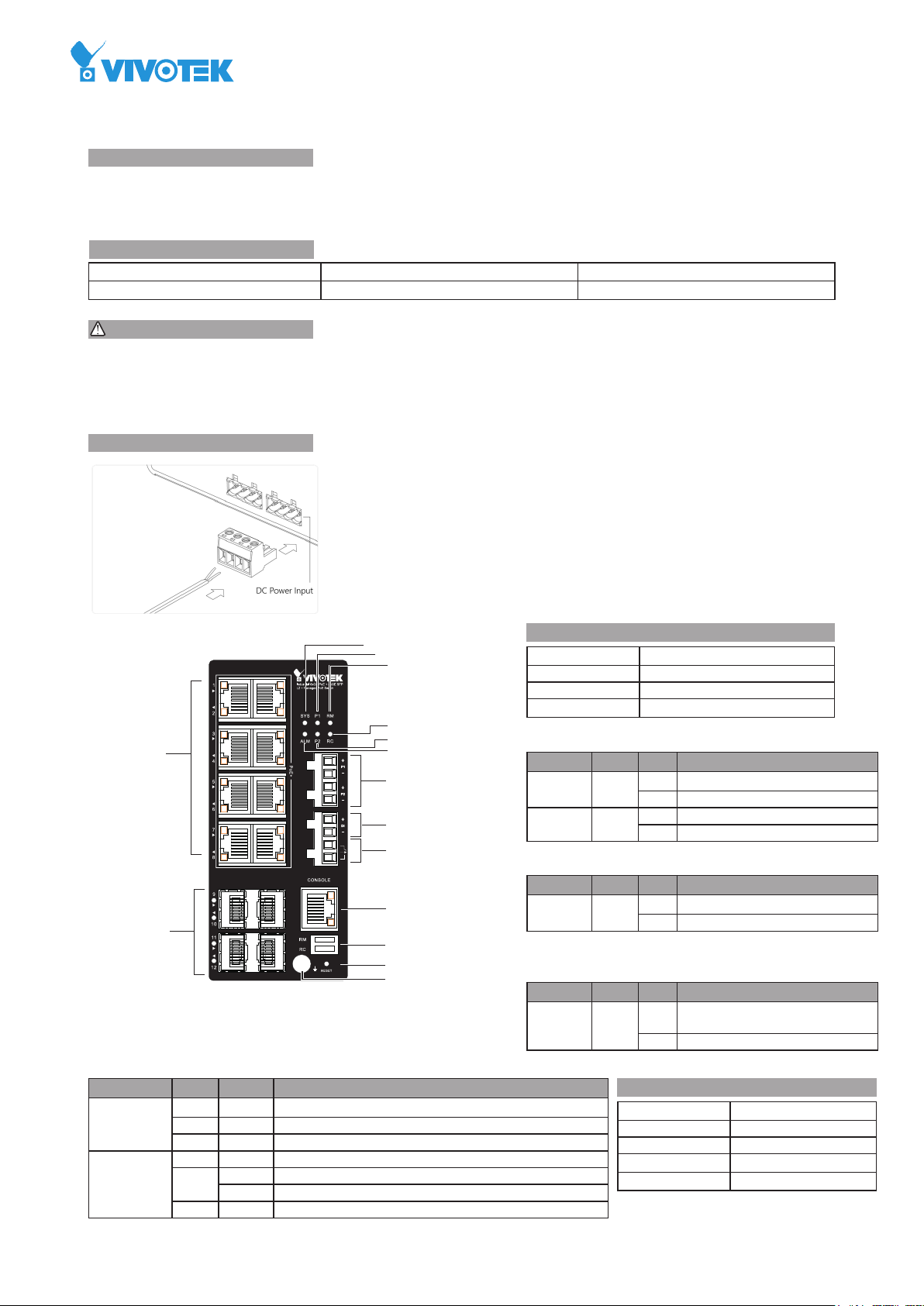
CONNECTION
1. Pull out the 4-pin terminal block.
2. Connect power wires to V+, and V-.
3. Connect SFP transceivers to the ber port.
4. install the 4-pin terminal block.
NOTE
: Digital output (relay): 24VDC/1A. Digital input: level 0(Low) -> 0V to 6V,
level 1(High) -> 10V to 24V.
DEFAULTS
IP Address
Subnet Mask
User Name
Password
Power LEDs
LED Color State Description
Power1 Green On Powered on correctly.
Power2 Green On Powered on correctly.
System LED
LED Color State Description
System Green On Switch is ready.
Alarm LED
LED Color State Description
Alarm Red On Abnormal state, such temperature,
DHCP client
255.255.255.0
admin
admin
Off Not receiving power from power1.
Off Not receiving power from power1.
Off Switch is not ready.
voltage, or DC power, has occurred.
Off System is normal.
Console Port Defaults
Baud rate
Stop bits
Data bits
Parity
Flow control
115200
1
8
N
none
10/100/1000
RJ45 ports
100/100
SFP ports
Ring Master and Rapid Chain LEDs
LED Color State Description
RM
(Ring Master)
RC
(Rapid Chain)
Green On Ring Master has been detected.
Amber On Ring Member has been detected.
- Off Disabled.
Green On Rapid Chain has been detected (Active path).
Amber On Rapid Chain has been detected (Backup path).
Blinking Error, there is no correspondent Rapid Chain switch found.
- Off Disabled.
System LED
Power1 LED
Ring Master LED
Rapid Chain LED
Power2 LED
Alarm LED
DC 54V power input
Digital input
Digital output relay
Console port
DIP switch (Ring Settings)
Reset button
Ground screw
Page 2
Port Status LEDs
LED Color State Description
RJ45 Ports UpGreen On The port is enabled and established a link to connected device, and the speed is 1000Mbps.
Green Blinking The port is transmitting/receiving packets, and the speed is 1000Mbps.
Amber On The port is enabled and established a link to connected device, and the speed is 10/100Mbps.
Amber Blinking The port is transmitting/receiving packets, and the speed is 10/100Mbps.
- Off The port has no active network connection, or it has no established link to connected device.
Otherwise, the port may have been disabled through the switch user interface.
RJ45 Ports
Down
Green On The port is enabled and supplying power to connected device.
Amber On An abnormal state, such as overload status, has been detected in the switch.
- Off The port has no active connection, or it is not connected to a PoE PD device. Otherwise, the port may
have been disabled through the switch user interface.
SFP Ports Green On The port is enabled and established a link to connected device, and the speed is 1000Mbps.
Green Blinking The port is transmitting/receiving packets, and the speed is 1000Mbps.
Amber On The port is enabled and established a link to connected device, and the speed is 100Mbps.
Amber Blinking The port is transmitting/receiving packets, and the speed is 100Mbps.
- Off The port has no active network connection, or it has no established link to connected device.
Otherwise, the port may have been disabled through the switch user interface.
Reset button
Task Method SYS LED Behavior Port Status LED Behavior
Reset Press 2 ~ 7 seconds Blinking Green All LEDs Off.
Restore Defaults Press 2 ~ 7 seconds Blinking Green All LEDS On.
RM: Ring Master
DIP Switch
RM
RC
2
RC: Rapid Chain
1
O N
Mode RM RC Rapid Ring status 1st Port 2nd Port LED RM LED RC
HW
Control
HW
Control
HW
Control
SW
Control
Off Off Single Ring member The largest Odd port
number
On Off Single Ring Master The largest Odd port
number
Off On Rapid Chain The largest Odd port
number
On On Rapid Ring settings
- - - -
by SW
The largest Even port
number
The largest Even port
number
The largest Even port
number
Amber Off
Green Off
Off Green (Active path);
Amber (Backup path)
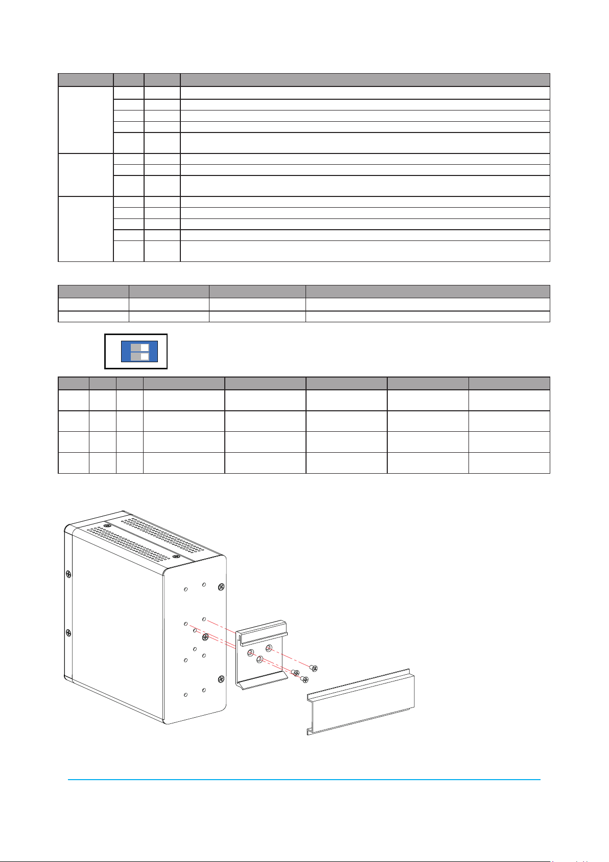
DIN Rail Installation
All specications are subject to change without noice.
Copyright © 2018 VIVOTEK INC. All rights reserved.
VIVOTEK INC.
6F, No.192, Lien-Cheng Rd., Chung-Ho, New Taipei City, 235, Taiwan, R.O.C.
|T: +886- 2-82455282|F: +886-2-82455532|E : sales@vivotek.com
VIVOTEK USA, INC.
2050 Ringwood Avenue, San Jose, CA 95131
|T: 408-773-8686| F: 408-773-8298| E: salesusa@vivotek.com
VIVOTEK Europe
Randstad 22-133, 1316BW Almere, The Netherlands
T: +31(0)36-5298-434 E: saleseurope@vivotek.com
 Loading...