

VIVO STAND-V002 Instruction Manual
Dual Monitor Desk Mount
Instruction Manual
SKU: STAND-V002
Scan the QR code with your mobile device or follow the link
for helpful videos and specifications related to this product.
https://vivo-us.com/products/stand-v002
GET IN TOUCH | Monday-Friday from 7:00am-7:00pm CST
help@vivo-us.com www.vivo-us.com 309-278-5303
Chat live with an agent!
WARNING!
If you do not understand these directions, or if you have any doubts about the safety of the
installation, please call a qualified technician. Check carefully to make sure there are no missing or
defective parts. Improper installation may cause damage or serious injury. Do not use this product
for any purpose that is not explicitly specified in this manual. Do not exceed weight capacity.
We cannot be liable for damage or injury caused by improper mounting, incorrect assembly or
inappropriate use.
TIPOVER WARNING
SERIOUS OR FATAL CRUSHING INJURIES CAN OCCUR FROM TIPOVER. TO HELP PREVENT TIPOVER:
• NEVER ALLOW CHILDREN TO CLIMB, STAND, HANG, OR PLAY ON ANY PART OF MONITOR OR
STAND.
• USE TIPOVER RESTRAINT OR ANCHOR STAND TO WALL
USE OF TIPOVER RESTRAINTS MAY ONLY REDUCE, BUT NOT ELIMINATE RISK OF TIPOVER.
WARNING: CHOKING HAZARD
SMALL PARTS - NOT FOR CHILDREN UNDER 3 YEARS. ADULT SUPERVISION IS REQUIRED.
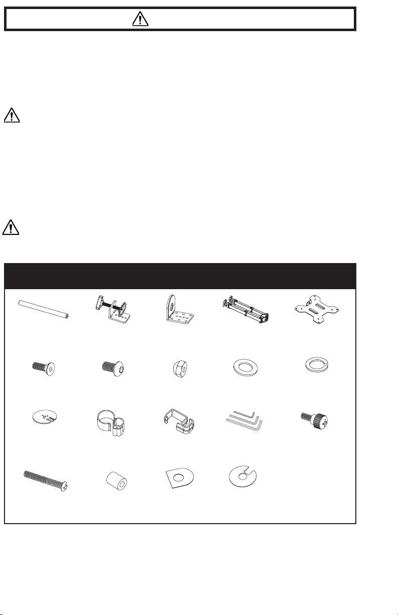
PACKAGE CONTENTS
2
A (x1)
Pole
F (x3)
M5x14 B olt
K (x1)
Grommet
Base Plate
O (x8)
M4x30 B olt
B (x1)
Clamp
G (x2)
M8x12 Bolt
L1 (x1)
Wire Clip
P (x8)
M4 Spacer
C (x1)
Clamp Brace
H (x2)
Nut
L2 (x4)
Wire Clip
Q1 (x1)
So Pad
D (x1)
Swivel Arm
I (x1)
M10 Washer
M (x1)
Allen Key Set
Q2 (x1)
So Pad
E (x2)
VESA Plate
J (x1)
Spring Washer
N (x8)
M4x12
Thumbscrew
NOTE: SOME HARDWARE INCLUDED MAY NOT BE USED
TOOLS NEEDED
t2
Figure 5
DO NOT EXCEED WEIGHT CAPACITY.
Failure to do so may result in serious injury.
Phillips
Screwdriver
ASSEMBLY STEPS
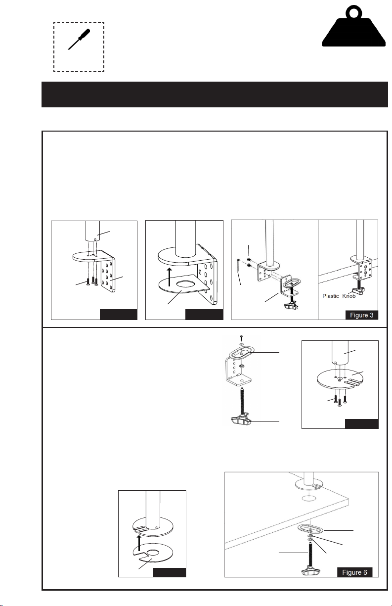
STEP 1
Option A: Desk Clamp Install
1. Install the clamp brace (C) to the pole (A) using x3 M5x14 bolts (F). See Figure 1.
2. Attach so pad (Q1) to the clamp brace (C) , see Figure 2.
3. Install the clamp (B) to the pole assembly according to the thickness of the desktop. The
thickness can be changed to 3 positions. Connect using x2 M8x12 bolts (G) and tighten using the
Allen wrench (M). Tighten the clamp to the desktop using the plastic knob. See Figure 3.
a
A
C
F
Figure 1
Q1
Figure 2
G
M
B
22 lbs
Per Arm
(10kg)
Option B: Grommet Install
1. If desk does not have an existing grommet
hole, drill a 3/8” (10mm) diameter hole at the
desired position through the mounting surface.
2. Completely disassemble clamp (B) into
individual parts. Set knob (B1) and clamp
plate (B2) aside for later use. The L bracket,
bolt, washer and bushing will not be used.
3. Install grommet base plate (K) to the pole (A)
using x3 M5x14 bolts (F). See Figure 4.
4. Attach so pad (Q2) to the grommet base plate
(K), see Figure 5.
5. Position pole (A) on the mounting surface
and secure using the clamp plate (B2), spring
washer (J), M10 washer (I) and knob (B1). See
Figure 6.
Q2
t2
Figure 5
B1
B2
B1
A
a
m
K
F
f
Figure 4
B2
J
I
3
 Loading...