

Vivo STAND-TV03N Instruction Manual

Black TV Floor Stand
Instruction Manual
SKU: STAND-TV03N
Scan the QR code with your mobile device or follow the link
for helpful videos and specifications related to this product.
https://vivo-us.com/products/stand-tv03n
GET IN TOUCH | Monday-Friday from 7:00am-7:00pm CST
help@vivo-us.com www.vivo-us.com 309-278-5303
Chat live with an agent!
WARNING!
If you do not understand these directions, or if you have any doubts about the safety of the
installation, please call a qualified technician. Check carefully to make sure there are no missing or
defective parts. Improper installation may cause damage or serious injury. Do not use this product
for any purpose that is not explicitly specified in this manual. Do not exceed weight capacity.
We cannot be liable for damage or injury caused by improper mounting, incorrect assembly or
inappropriate use.
TIPOVER WARNING
SERIOUS OR FATAL CRUSHING INJURIES CAN OCCUR FROM TIPOVER. TO HELP PREVENT TIPOVER:
• NEVER ALLOW CHILDREN TO CLIMB, STAND, HANG, OR PLAY ON ANY PART OF TV OR TV CART.
• USE TIPOVER RESTRAINT OR ANCHOR STAND TO WALL
USE OF TIPOVER RESTRAINTS MAY ONLY REDUCE, BUT NOT ELIMINATE RISK OF TIPOVER.
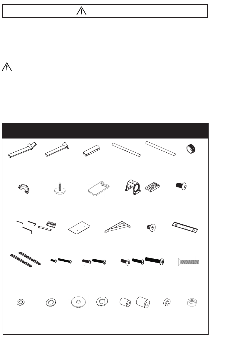
PACKAGE CONTENTS
1 (x1)
Le Base
7 (x4)
Pole
Cover
M2.5
Phillips
17 (x1)
VESA Bracket
Set
22 (x4)
M4 Washer
M4
12 (x1)
Too l Ki t
2 (x1)
Right Base
8 (x2)
RubberFoot
18 (x4)
M4x12
M4x30
23 (x14)
M6 Washer
Connector
13 (x1)
Shelf
24 x2)
Silver M6
washer
3 (x1)
Base
9 x2)
Suppor t Feet
and Pads
Shelf Support
19 (x4)
M6x20
M6x35
25 (x4)
M8 Washer
Base Pole
14 (x2)
4 (x2)
10(x2)
Plate Connector
and Plastic Shim
20 (x4)
M8x20
M8x35
M8x45
26 (x4)
M4 Spacer
M6/8 Spacer
(20mm)
15 x4)
M4x6
5 (x2)
Top Pole
27 (x8)
M6/8 Spacer
(5mm)
6 (x2)
Pole Connector
11 x20)
M6x10
16 x1)
Mounting
Plate
21 x2)
M6x29
28 (x2)
M6 Nut
NOTE: SOME HARDWARE INCLUDED MAY NOT BE USED
2
TOOLS NEEDED
Phillips
Screwdriver
DO NOT EXCEED WEIGHT CAPACITY.
Failure to do so may result in serious injury.
110 lbs
(49.9 kg)
CART SHELF
WARNING: CHOKING HAZARD
SMALL PARTS - NOT FOR CHILDREN UNDER 3 YEARS. ADULT SUPERVISION IS REQUIRED.
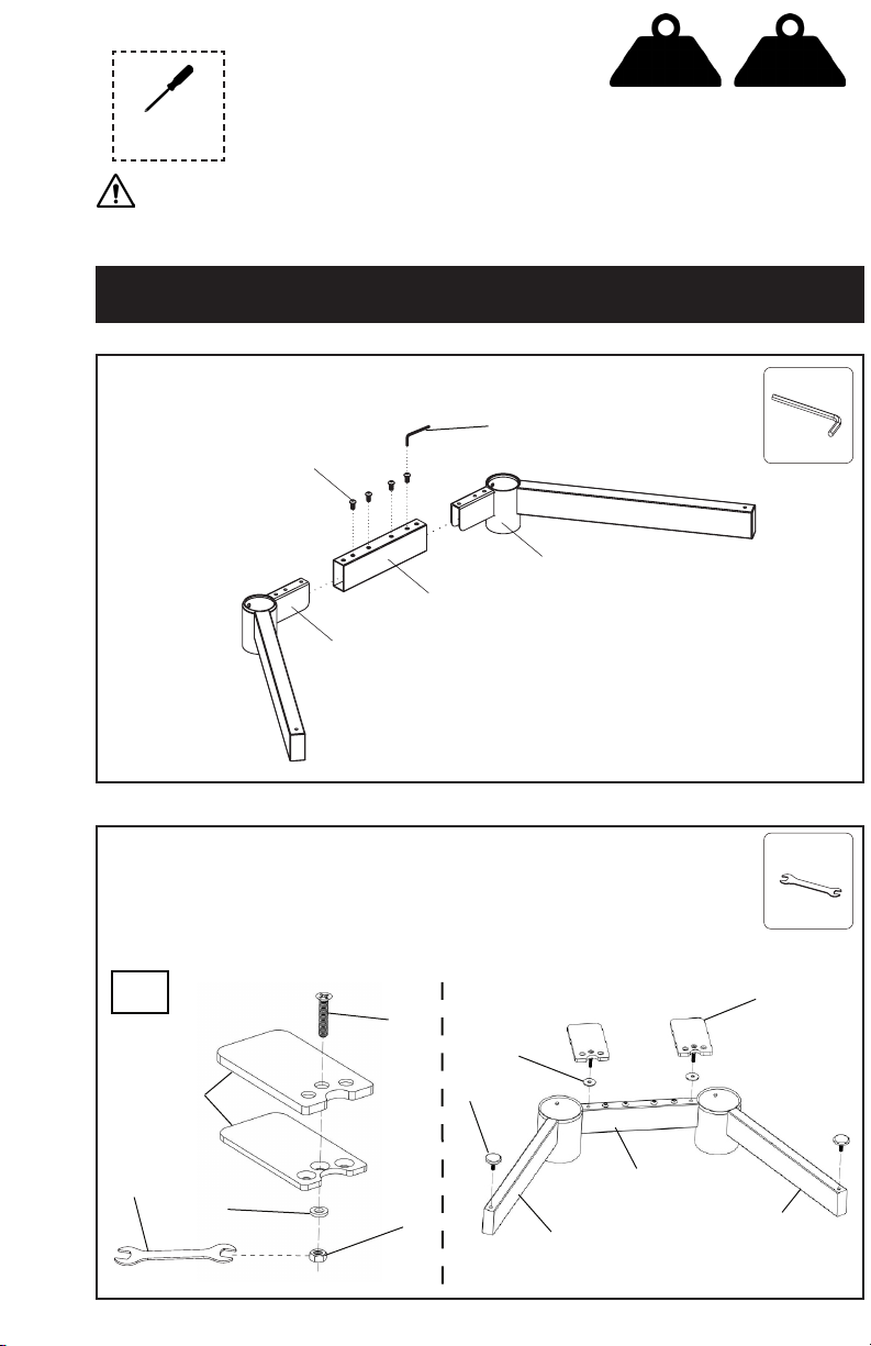
ASSEMBLY STEPS
STEP 1
Attach le and right base (1, 2) to the base connector (3) using M6x10 bolts (11).
Tighten with the 4mm Allen wrench (12).
12
10
11
1
3
2
10 lbs
(4.54 kg)
12
M4
x1
STEP 2
Assemble both of the Support Feet and Pads (9) using the M6x29 bolt (21), M6 washer
(23), and nut (28). Tighten using the Wrench (12). Spin both of these onto the Base
Connector (3) by hand while using the washer (24). When the Support Feet (9) are fully
seated, loosen it no more than a full turn to position them so they face backwards as
shown below. Then spin on the Rubber feet (8) onto the Right and Le Base (1,2).
2x
21
24
9
12
23
8
3
28
2
12
x1
9
1
3
 Loading...