

Vivo DESK-V101E, DESK-V100E Assembly Instructions Manual

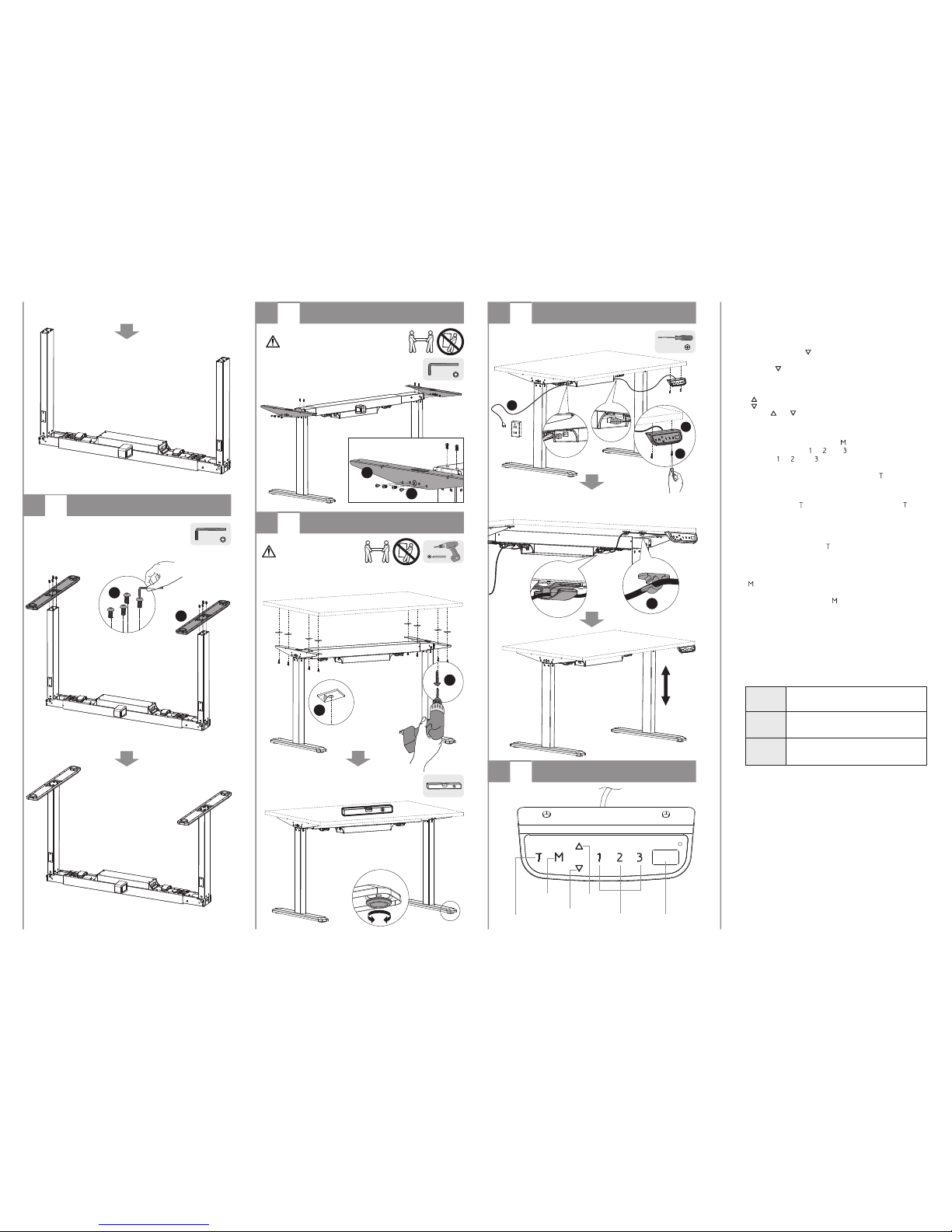
·Loosen the screws using the Allen key.
·Remove the hexagon rod.
A
1
Adjusting the Frame
·Adjust the extension frame length to
suit the desktop and tighten all screws
to secure the extension frame in place.
·Loosen the cross-head screws using
an appropriate screwdriver.
·Loosen the hexagon socket button
head screws using the Allen key.
hexagon rod
cross-head screw
hexagon socket button
head screw
C
base support
(x2)
F
control panel
(x1)
G
power cord
(x1)
S-B (x2)S-A (x24)
B (x2)
upper support
S-D
Allen key
(x1)
S-E
cable clip
(x3)
S-F
rubber pad
(x8)
A
telescopic frame
(x1)
D
lifting column
(x1)
E
lifting column
(x1)
Tools
Needed
ASSEMBLY INSTRUCTIONS
Height Adjustable Desk Frame
ELECTRIC
Model: DESK-V101E
product is not intended for use by young children without supervision.
This product contains small items that could be a choking hazard if
swallowed. Keep these items away from children.
This product is intended for indoor use only. Using this product outdoors
could lead to product failure and personal injury.
IMPORTANT: Ensure that you have received all parts according to the
component checklist prior to installation. If any parts are missing or
faulty, telephone your local distributor for a replacement.
This
CAUTION:
·This product can be used under the standard technical parameters only.
·Please place the product away from corrosive gas, water and dusty
environment.
·Please do not disassemble the pre-assembled components, as this will
void the warranty.
QUICK TIP: DO NOT over tighten screws during installation.
Important information
Read the entire instruction manual before you start
installation and assembly.
WARNING: FAILURE TO COMPLY WITH OR OBSERVE ALL
ASSEMBLY, SAFETY AND OPERATION INSTRUCTIONS AND
WARNINGS REGARDING THE USE OF THIS PRODUCT MAY
RESULT IN SERIOUS BODILY INJURY.
WARNING
Component Checklist
S-C (x8)
·Insert the previously removed hexagon rod through the hole in the lifting column.
2
Assembling the Lifting Columns
S-A
·Attach the lifting columns to the frame using the proper screws
and tighten all screws with the Allen key.
extension frame
C
B
S-A
7
Installing the Control Panel
Downward
movement
Upward
movement
Memory 1 / 2 / 3
Memory
/Screen lock
(unlock)
Timer
Display
·Attach the control panel to the back of desktop using
the appropriate screws.
·Tighten all screws to secure.
·Remove the protective film from the adhesive cable clips.
·Stick the cable clips to the back of the desktop.
·Run the cables through the cable clips.
Note:
1. The controller will start the self-protected function when the system runs
continuously for two minutes with “ HOT ” shown. The system will return to
normal after eighteen minutes.
2. Over-current protection: If the load exceeds 900N when operating the desk
upwards, the system will start the over-current protection. At this time, the desk
will run downwards automatically for 10mm and stop, with the current height
displayed.
If there are any obstacles when running downwards, the system will start the
over-current protection. At this time, the desk will run downwards automatically
for 10mm and stop. “ ER1 ” will occur after three continuous over-current
protections, please reset for normal operation. (Reset: Touch “ DOWN ” over 5
seconds for the automatic system reset.)
3. Attention: Please do not cut off the power supply to reset and operation during
the “ HOT ” state.
Description
ER1
Overload in downwards direction has occurred
and needs to be reset.
ER2
Over-heating in the controller has occurred
and needs to cool.
Error Code
Below are the possible error codes that may be displayed on the control panel.
Operation Instruction:
1. When the system is powered up ( Input: 100V AC-240 V AC), the buzzer will
beep with the current height displayed.
2. Reset
When power is on, touch “ ” and do not release until the desk is in the fully
lowered position, and the display will show “ ER1 ” or “ 75.0 ” (unit: cm). In either
case, touch “ ” and hold for 5 seconds, and the system will reset automatically
with “ RST ” displayed. After resetting, the display will show “ 75.0 ” (unit: cm),
which is the current height.
3. Upward movement
Downward movement
Touch the “ ” or “ ” and do not release until the desk reaches the desired
height.
4. Memory
To store a position in memory, first touch “ ” and “ S- ” will be displayed.
Within five seconds, touch “ ”, “ ”, or “ ” to store the position in memory.
The buttons “ ”, “ ”, and “ ” can each store a different height setting. After
setting, the system will automatically adjust to the stored height associated with
the numbered button used. Touching any buttons (except “ ” ) will stop the
automatic adjustment.
5. Timed Reminder
To set the timer, touch “ ” and the display will flash “ 0.5h ”. Touch “ ”
repeatedly to increase in steps of 0.5 hours. The maximum set time is two hours.
The timer is successfully set when the digit stops flashing and the light in the top
right corner is on. When time is up, the buzzer will beep to remind the user of the
working position adjustment, then the timer will automatically be cancelled. To
deactivate a timed reminder, touch “ ” five times until the current height is
displayed and the light in the top right corner is off.
6. Screensaver Mode
To prevent a misoperation by accidentally touching the buttons, touch and hold the
“ ” button for 3 seconds. The screensaver is activated when the display shows
“ --- ”. The screensaver will also be activated when there are no actions made for
over 90 seconds. Touch and hold the “ ” button for 3 seconds to deactivate the
screensaver.
7. Power-saving Mode
When no actions are made for over 10 minutes, the system will enter power-saving
mode. Touch any button to enter operation mode.
Trouble Shooting
S-C
S-B
F
HEAVY!
An assistant is needed for this step.
5
Installing the Upper Supports
·Turn the desk frame upright onto a level surface.
·Attach the two upper supports to both ends of the frame using
the screws provided and tighten all screws with the Allen key.
· Remove the protective film from the rubber pads.
· Stick the rubber pads to the frame.
· Attach the desktop to the frame using the proper screws.
· Tighten all screws to secure.
6
Installing the Desktop (Optional)
HEAVY!
An assistant is needed for this step.
8
Operating Controller
S-F
S-E
· Each foot pad can be adjusted independently for fine tuning.
· Slightly turn the foot pad to lower or raise the base.
· Use a level to make sure the desktop is even.
G
3
Installing the Base Supports
·Attach the base supports to the lifting columns using the
eight screws provided and tighten all screws to secure.
S-A
 Loading...