

Vivitek RP56HD21 Service Manual
Service Manual
RP56HD21
Revision Description Date
Approvals:
__________________________________ ____________
__________________________________ ____________
Marketing Date
__________________________________ ____________
__________________________________ ____________
Engineering Date

CONTENTS
I. Engineering Specifications...............................................................................................................................1
1. Summary specifications ..........................................................................................................................1
2. Introduction..............................................................................................................................................3
2.1. Digital Light Processing(DLP) by Texas Instruments .................................................................3
2.2. DCDi deinterlacing/enhancement chipset ..................................................................................3
2.3. Key Features ..............................................................................................................................3
2.3.1. Optical ..............................................................................................................................3
2.3.2. Mechanical .......................................................................................................................3
2.3.3. Electrical ...........................................................................................................................3
2.3.4. Power Supply ...................................................................................................................4
2.3.5. Packaging.........................................................................................................................4
2.4. Supplied Accessories.................................................................................................................4
2.5. Service .......................................................................................................................................4
2.6. Safety .........................................................................................................................................4
3. Optical .....................................................................................................................................................5
3.1. Illumination & Imaging Optics.....................................................................................................5
3.1.1. Projection Lens.................................................................................................................5
3.1.2. Color wheel.......................................................................................................................5
3.1.3. LAMP-Philips ....................................................................................................................5
3.2. Brightness,Uniformity,Contrast...................................................................................................6
3.3. Color...........................................................................................................................................6
3.4. Image .........................................................................................................................................7
3.5. DMD ...........................................................................................................................................7
3.5.1. Resolution and Display Type ............................................................................................7
3.5.2. Defects..............................................................................................................................7
3.6. Definitions...................................................................................................................................8
4. Electrical..................................................................................................................................................8
4.1. Input and Output Signal Levels ..................................................................................................8
4.2. Video Compatibility & Re-sizing ...............................................................................................11
4.2.1. Re-sizing.........................................................................................................................11
4.2.2. Data ................................................................................................................................11
4.2.3. Video...............................................................................................................................11
4.2.4. TVs Channel Table. ........................................................................................................12
4.3. User interface ...........................................................................................................................19
4.3.1. Hardware function ( Rear) ..............................................................................................19
4.3.2. SIDE:............................................................................................................................22
4.3.3. Control keypad.............................................................................................................22
4.3.4. Remote control keypads.................................................................................................23
5. Mechanical ............................................................................................................................................24
5.1. Outline Dimensions ..................................................................................................................24
5.2. Environmental ..........................................................................................................................24
5.3. Packaging/Shipping..................................................................................................................24
5.4. Construction Materials .............................................................................................................24
i

5.5. Clean Air Filters........................................................................................................................25
5.6. Cooling system: .....................................................................................................................25
5.7. Acoustic noise:.......................................................................................................................25
6. Safety ....................................................................................................................................................25
6.1. Interlocks ..................................................................................................................................25
6.2. Labels.......................................................................................................................................25
II. On-Screen Display Function Control Description ..........................................................................................26
1. Functional Requirements ......................................................................................................................26
2. OSD Flow chart .....................................................................................................................................29
III. Circuit Description..........................................................................................................................................47
1. Circuit Description .................................................................................................................................47
2. Hardware platform description ..............................................................................................................51
2.1. I/P board PCBA(Refer to picture 1).....................................................................................51
2.2. Power supply PCBA (Refer to picture 2) ............................................................................53
2.3. A/V board PCBA(Refer to picture 3)....................................................................................55
2.4. Keypad ECA & IR PCBA(Refer to picture 4).......................................................................56
2.5. Audio board PCBA(Refer to picture 5) ................................................................................56
2.6. Tuner board PCBA(Refer to picture 6)................................................................................57
IV. Troubleshooting Flow Chart ...........................................................................................................................59
1. NO POWER ( POWER LED OFF) ........................................................................................................61
2. NO PROJECTION LIGHT ( NO PICTURE) ..........................................................................................62
3. OSD NOT OPERATING ........................................................................................................................63
4. VIDEO NO IMAGE( CVBS ,S-VIDEO ,Y/Cb/Cr) ...................................................................................63
5. NO AUDIO.............................................................................................................................................64
6. NO TV OR LOST SOME CHANNEL.....................................................................................................64
7. PROTECTION IMAGE IS ABNORMAL.................................................................................................65
V. PCB Layout Diagram .....................................................................................................................................66
VI. Mechanical Assembly ....................................................................................................................................67
VII. Adjustment of Picture.....................................................................................................
................................73
VIII. Recommended Spare parts list ......................................................................................................................75
IX. Download Procedure (USE RS-232) .............................................................................................................78
ii

I. Engineering Specifications
1. Summary specifications
Performances Specification
Display type One 0.8” 1280 x 720 DLP.
Resolution supported VGA (640x480) expansion.
SVGA (800x600) expansion.
DTV(1280x720 p) native.
HDTV (1920x1080 i). compression
Colors 16.7M
Bandwidth 80 MHz
Weight < 130 Lb.
Image size (diagonal) 56 inch.
Brightness 400 nits
Brightness uniformity Better than 80%
Projection lens Fixed.
Projection method Rear.
Computer Compatibility IBM PC or Compatibles(VGA, SVGA, XGA), DVI input.
Video Compatibility NTSC/NTSC4.43, PAL, PAL 60,
PIP YES
POP YES
DCDi YES
H-Sync , V-Sync 30~60KHz, 50~85Hz.
Safety Certification UL, C-UL, FCC Class B, CCC, BASEC/BS, BSMI
Operation temperature 5~35 °C
Dimensions 1381mm(W) x 1113mm (H) x 480mm (D)
Power requirements 90-264VAC,50-60HZ,autoranging
Power Consumption 300W max, 250W typical
Standby < 3W
Lamp UHP , 120W.
Audio Speaker 15W x 2
BBE system and SRS system
Remote control Hand-held remote.
Data signal level Analog RGB:0.7Vpp/75 Ω.
H,V sync:Separate, TTL level, negative or positive
Digital Visual Interface Digital encoder signal:High 5V , Low 0V.
Video signal level Composite video:1.0Vpp/75Ω, Sync negative.
S-video Y:1.0Vpp/75Ω, Sync negative.
C
PAL 0.3Vpp/75Ω.
Components video Y:1.0Vpp/75 ohm, Sync negative.
Pb/Cb:0.7Vpp/75 ohm.
Pr/Cr:0.7Vpp/75 ohm.
:
NTSC 0.286Vpp/75Ω.
Page1 of 79

Audio signal level 0.5Vrms/47kΩ.
Input terminal (Side) PC:D-sub 15pin x 1
AV:S-Video x 1, Composite Video x 1
Audio:3.5mm stereo mini jack x 1
Input terminal (Rear ) PC:D-Sub 15pin x 1 and DVI x 1
AV:S-Video x 2, Composite Video x 2,YPbPr x 2
RF:F - TYPE x 1 (model name:RP56HD21-A/T)
I - TYPE x 1 (model name:RP56HD21-C)
Audio:3.5mm stereo mini jack x 1for D-sub 15pin
RCA (Red/White) x 1 for DVI
RCA (Red/White) x 2 for video
RCA (Red/White) x 2 for component
Out terminal AUDIO:RCA (Red / White) x 1
Earphone – Main x 1 and Sub x 1 (Side)
Page2 of 79

2. Introduction
The DVR5610 is a Rear Projection multi purpose display unit integrating DLP(Digital Light Processing)
technology that is targeted for multi media application and data processing applications. As such it will excel in
displaying real time video and graphics.
2.1. Digital Light Processing(DLP) by Texas Instruments
DLP5610 is a projection unit using a Texas Instruments’ Digital Light Processing(DLP) technology optical
engine.
DLP system is constructed with the 1280 x 720 -DME(Digital Multi- media Engine) using s one- chip Digital
Micromirror Device(DMD)
2.2. DCDi deinterlacing/enhancement chipset
By Using FLI2300 video processing of Faroudja , Its feature including DCDi deinterlacing, reverse 3:2
pulldown film mode, motion adaptive 3D video noise reduction, cross-color artifact suppression and nonlinear
enhancement functions.
2.3. Key Features
2.3.1. Optical
Philips UHP-120W AC lamp system
400 nits using 0.8” HD2 DLP.
80% ANSI brightness uniformity (9pt ANSI)
1000:1 contrast ratio (full-on ,full-off )
2.3.2. Mechanical
1381mm(W) x 1113mm (H) x 480mm (D)
The weight less than 130 lbs.
“Four point” foot system for stability
On screen display for inputs source select, keypads inputs intuitive
Target noise level less than 33db
Detachable connectors.(A/V:include Video phone jack , S-video & Audio phone jack, Earphone
jack, (Data include Analog Mini D-sub 15pin, Digital DVI 24pin). and RF input.
2.3.3. Electrical
Dual DB-15pin connector for computer input Rear x1 , Front x1, 1280 x 720 native resolution)
Digital DVI 24pin for computer input.
Video input (3sets Video RCA jacks, 3sets S-video mini Din, 2set Components/HDTV video.
Audio input(6 sets Audio RCA jacks , Phone jack x 2sets for Data).
NTSC, NTSC4.43, and PAL video compatible
Lamp standby feature.
2 split of PIP/POP feature.
1x12, 1+ 7 and side by side picture.
Design in SRS/BBE system.
Two tuners for Cable and air TV.
Page3 of 79

2.3.4. Power Supply
Auto-ranging from 90 to 264 VAC @ 50 to 60 Hz
Power consumption:300watts max. ,250watts typical.
2.3.5. Packaging
Cardboard with foam inserts
Anti-static plastic bag protects unit
2.4. Supplied Accessories
6.5 ft. IEC detachable Power cord.
Remote control, and two AAA batteries.
PIP remote control, and two AA batteries.
User Manual, and remote control manual
Warranty Card.
2.5. Service
MTBF estimated 20,000 hours min.
Lamp life 6000 hours (As Philips definition)
User replacement parts
Lamp module
Clean air filters
Service center replacement parts
Optical engine assembly.
Electronics/Power supply module/Ballast module.
Fans.
RS232 download.
2.6. Safety
UL/CUL
FCC class B
Locked rotor detection – auto shutdown
CCC,BASEC/BS (model name:RP56HD21-C)
BSMI (model name:RP56HD21-T)
Page4 of 79
3. Optical
The optical specifications are divided into component specifications and projector performance specifications.
3.1. Illumination & Imaging Optics
3.1.1. Projection Lens
Specification Units Minimum Maximum Typical Notes
Fixed lens
Focal length
Distortion
MTF(36lp/mm)
Center
Lateral color
F #
Mm
%
%
>80
2.5
13.2
<1.0
<1 pixel
3.1.2. Color wheel
Specification Units Minimum Maximum Typical Notes
Number of pairs
Color segments
deg G:55
R:75
B:50
G:55
R:75
B:50
3.1.3. LAMP-Philips
Specification Units Minimum Maximum Typical Notes
Lamp Type /
Ballast
Life 6000hrs As Philips definition
Philips UHP
120W/1.3
Philips EUC
120P/H11(H00)
Page5 of 79
3.2. Brightness,Uniformity,Contrast
Specification Units Minimum Maximum Typical Notes
White field nits TBD 360 400 Using ANSI 9 point avg.
Uniformity
Brightest
Dimmest
Contrast ratio Ratio 1000:1 Dark room measurement
Note:Specifications TBD at prototype phase
Percent >80%
>85%
Using ANSI 9 point
(full-on , full-off)
3.3. Color
Specification Units Minimum Maximum Typical Notes
Color Temperature K 7500
White color CIE x,y
x 0.265 0.325 0.295
y 0.314 0.374 0.344
Red color
x 0.629 0.689 0.659
y 0.317 0.377 0.347
Green color
x 0.274 0.334 0.304
y 0.556 0.616 0.586
Blue color
x 0.114 0.174 0.144
y 0.057 0.117 0.087
Color Uniformity
△
(u’,v’)
Note:The color values and uniformity tolerances are to be measured using the 9pt. ANSI standard.
0.015 <0.010
Page6 of 79

3.4. Image
Specification Units Minimum Maximum Typical Notes
Viewable screen size
Diagonal
Width
Height
Screen
Type
Gain
Viewing angle
Horizontal
Vertical
Viewable Pixel Pixel 1270x710 1280x720 Overscan
Geometric distortion pixel 5 0 Relative to the frame edge
Note:Specifications TBD at prototype phase
Inch
mm
mm
mm
degree
56”(16:9)
480
1381
1113
4.0
50
18
Two-part screen composed
of a front UCS type
lenticular and a back
fresnel lens.
Relative to normal axis of
screen
3.5. DMD
3.5.1. Resolution and Display Type
Specification Units Maximum Minimum Typical Notes
Resolution Native 1280x720
Horizontal 1280
Vertical 720
Display Type DLP 0.8” HD2
3.5.2. Defects
SEQ # TEST SCREEN ACCEPTANCE CRITERIA
1 Major Dark Blemish Blue 90 No visible blemishes darker than Blue 90
2 Dark Pixel Blue 90
Zoned Screen
3 Major Light Blemish Gray 10 No blemishes brighter than Gary 10
4 Light Pixel Gray 10 No pixels brighter than Gary 10
5 Minor Blemishes White or Black Total of Dark and Light Blemishes ≦ 6
6 Unstable Pixel Red Ramp Screen (or any other) No unstable Pixels
≦
1 dark pixel allowed in Zone A
≦
4 dark pixel allowed in ZoneS A+B
No adjacent dark pixels
Page7 of 79
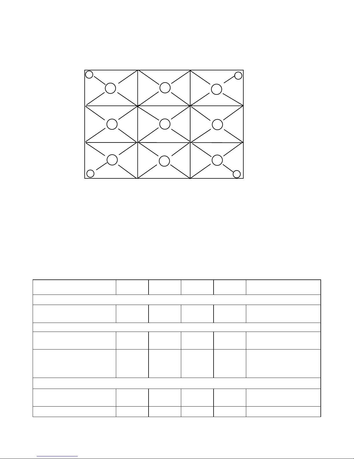
3.6. Definitions
The full white pattern is defined as an all white screen produced by 0.7V video input to R,G,B.
10
11
1 2 3
654
Note:All measurements are done in a darkened room. Contrast measurements are done using a full white
screen and a full black screen.
Note:The uniformity calculations for brightnessis to be done using the following formula:
Brightest:[(Max-Average Brightness)/Average Brightness]*100
Dimmest:[(Average Brightness-Min)/Average Brightness]*100
13
7 8
9
12
4. Electrical
4.1. Input and Output Signal Levels
Specification Units Minimum Maximum Typical Notes
Video input amplitude.
Composite video (CVBS)
Sync negative.
S-video.
Luminance (Y)
Sync negative.
Chrominance (C)
NTSC color burst signal.
PAL color burst signal.
V p-p 1.0 75 ohm.
V p-p 1.0 75 ohm.
V p-p
V p-p
0.286
0.3
75 ohm.
75 ohm.
Components video.
Luminance (Y)
Sync negative.
Chrominance (Pb/Cb/B-Y) V p-p 0.7 75 ohm
V p-p 1.0 75 ohm
Page8 of 79
Specification Units Minimum Maximum Typical Notes
Chrominance (Pr/Cr/R-Y) V p-p 0.7 75 ohm
Audio input amplitude
R/L audio input. V rms 0.5 47K ohm
Frequency
NTSC Video
Horizontal
Vertical
PAL Video
Horizontal
Vertical
Components Video(1080i)
Horizontal
Vertical
Components Video(720p)
Horizontal
Vertical
Components Video(480p)
Horizontal
Vertical
MHz
KHz
Hz
MHz
KHz
Hz
MHz
KHz
Hz
MHz
KHz
Hz
MHz
KHz
Hz
6.0
640 x 480 interlace
15.734
60
8.0
640 x 480 interlace
15.625
50
74.25
1920 x 1080 interlace
33.75
60/50
74.25
1280 x 720 progressive
45
60
27
progressive
31.469
59.94
Dot clock MHz 80
Horizontal frequency kHz 30 60
Vertical frequency Hz 50 85
Sync lock Will not lose sync lock with
signal inputs within stated
frequency range.
Total pixels per line Pixels 1280displayed
Active vertical lines # of HS 720displayed
Page9 of 79
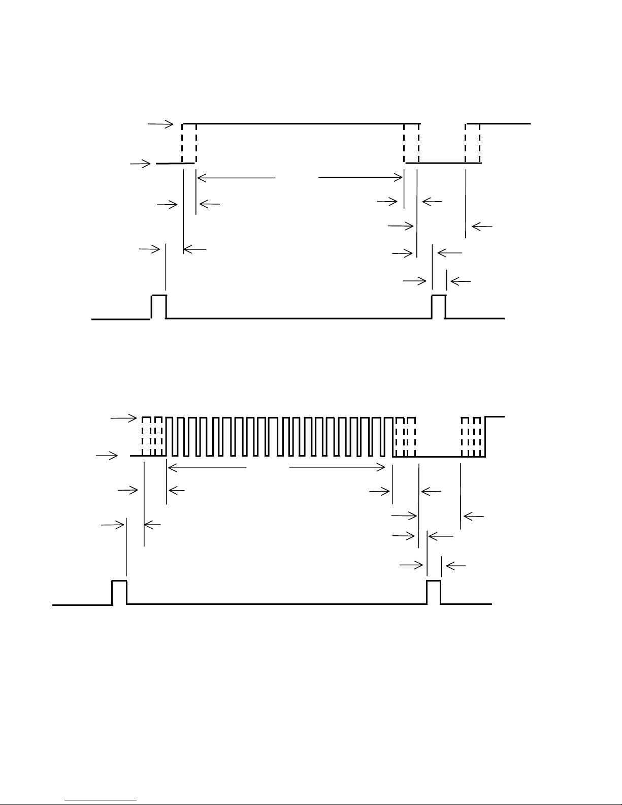
Horizontal Timing Intervals
Vertical Timing Intervals
0.700 volt
0.000 volt
Leading Border
60
Video
Trailing Border
Blanking
Back Porch
Front Porch
Sync polarity may be inverted
for some modes
Sync
0.700 volt
0.000 volt
Video
Leading Border
Trailing Border
Back Porch
Front Porch
Sync
Sync polarity may be inverted for some modes
Blanking
Page10 of 79
4.2. Video Compatibility & Re-sizing
4.2.1. Re-sizing
Specification Units Minimum Maximum Typical Notes
Total pixels per line Pixels 640 1920 1280 1280 displayed
Active vertical lines # of HS 350 1080 720 720 displayed
Resizing From To
Video NTSC/PAL/SECAM/YPbPr
/YCbCr
High TV
4:3
Full screen
16:9
4.2.2. Data
Mode Name(s) Used Horiz. Res. Vert. Res.
Native Mode 1280 720
TV Video Modes
NTSC TV mode 700 525
PAL TV mode 700 625
VGA Modes
VGA Text 720 400
VESA Modes
VGA/60 Hz 640 480
VGA/72 Hz 640 480
VGA/75 Hz 640 480
VGA/85 Hz 640 480
VGA/72 Hz 640 480
SVGA/56 Hz 800 600
SVGA/60 Hz 800 600
SVGA/72 Hz 800 600
SVGA/75 Hz 800 600
SVGA/85 Hz 800 600
XGA/60 Hz 1024 768
XGA/70 Hz 1024 768
XGA/75 Hz 1024 768
4.2.3. Video
NTSC/ NTSC4.43 Chroma subcarrier frequency, 3.58 MHz & 4.43 MHz
PAL CCIR, Chroma subcarrier frequency, 4.43 MHz
Components input (YPbPr)(YCbCr) HDTV compatible (480i/480p/720p/1080i).
Page11 of 79

4.2.4. NTSC TVs Channel Table
TV
CH
CATV
CH
Picture Carrier (MHz)
TV/STD CATV HRC CATV IRC
1 2 2 55.25 54.00 55.25
2 3 3 61.25 60.00 61.25
3 4 4 67.25 66.00 67.25
4 1 73.25 72.00 73.25
5 5 5 77.25 78.00 79.25
6 6 6 83.25 84.00 85.25
7 95/A-5 91.25 90.00 91.25
8 96/A-4 97.25 96.00 97.25
9 97/A-3 103.25 102.00 103.25
10 98/A-2 109.25 108.00 109.25
11 99/A-1 115.25 114.00 115.25
12 14/A 121.25 120.00 121.25
13 15/B 127.25 126.00 127.25
14 16/C 133.25 132.00 133.25
15 17/D 139.25 138.00 139.25
16 18/E 145.25 144.00 145.25
17 19/F 151.25 150.00 151.25
18 20/G 157.25 156.00 157.25
19 21/H 163.25 162.00 163.25
20 22/I 169.25 168.00 169.25
21 7 7 175.25 174.00 175.25
22 8 8 181.25 180.00 181.25
23 9 9 187.25 186.00 187.25
24 10 10 193.25 192.00 193.25
25 11 11 199.25 198.00 199.25
26 12 12 205.25 204.00 205.25
27 13 13 211.25 210.00 211.25
28 23/J 217.25 216.00 217.25
29 24/K 223.25 222.00 223.25
30 25/L 229.25 228.00 229.25
31 26/M 235.25 234.00 235.25
32 27/N 241.25 240.00 241.25
33 28/O 247.25 246.00 247.25
34 29/P 253.25 252.00 253.25
35 30/Q 259.25 258.00 259.25
36 31/R 265.25 264.00 265.25
37 32/S 271.25 270.00 271.25
38 33/T 277.25 276.00 277.25
Page12 of 79

39 34/U 283.25 282.00 283.25
40 35/V 289.25 288.00 289.25
41 36/W 295.25 294.00 295.25
42 37/AA 301.25 300.00 301.25
43 38/BB 307.25 306.00 307.25
44 39/CC 313.25 312.00 313.25
45 40/DD 319.25 318.00 319.25
46 41/EE 325.25 324.00 325.25
47 42/FF 331.25 330.00 331.25
48 43/GG 337.25 336.00 337.25
49 44/HH 343.25 342.00 343.25
50 45/II 349.25 348.00 349.25
51 46/JJ 355.25 354.00 355.25
52 47/KK 361.25 360.00 361.25
53 48/LL 367.25 366.00 367.25
54 49/MM 373.25 372.00 373.25
55 50/NN 379.25 378.00 379.25
56 51/OO 385.25 384.00 385.25
57 52/PP 391.25
58 53/QQ 397.25
59 54/RR 403.25 402.00 403.25
60 55/SS 409.25 408.00 409.25
61 56/TT 415.25 414.00 415.25
62 57/UU 421.25 420.00 421.25
63 58/VV 427.25 426.00 427.25
64 59/WW 433.25 432.00 433.25
65 60/XX 439.25 438.00 439.25
66 61/YY 445.25 444.00 445.25
67 62/ZZ 451.25
68
69
70
71
72 66
73
74
67
75
76
68
77
TV
CH
63/AAA 457.25
14
15
16
17
CATV
CH
64/BBB 463.25
65/CCC
TV/STD CATV HRC CATV IRC
469.25 468.00 469.25
471.25
475.25
477.25
481.25
483.25
487.25
489.25
Picture Carrier (MHz)
390.00
396.00
450.00
456.00
462.00
474.00
480.00
486.00 487.25
391.25
397.25
451.25
457.25
463.25
475.25
481.25
Page13 of 79

78 69 493.25 492.00 493.25
79 18 495.25
80 70 499.25
81 19 501.25
82 71 505.25 504.00 505.25
83 20 507.25
84 72 511.25 510.00 511.25
85
86
87 22 519.25
88 74 523.25 522.00 523.25
89 23 525.25
90 75 529.25
91 24 531.25
92
93
94
77
95 26
96 78 547.25
97 27 549.25
98 79 553.25 552.00
99 28 555.25
100 80 559.25 558.00 559.25
101 29 561.25
102
103 30 567.25
104 82 571.25 570.00 571.25
105
106
83
107
108 84 583.25 582.00 583.25
109 33 585.25
110 85 589.25 588.00 589.25
111 34 591.25
112 86 595.25 594.00 595.25
113 35 597.25
114 87 601.25 600.00
115 36 603.25
116 88 607.25 606.00 607.25
TV
CH
21 513.25
25 537.25
31
32
CATV
CH
TV/STD CATV HRC CATV IRC
73 517.25 516.00 517.25
76
535.25
541.25
543.25
81 565.25 564.00 565.25
573.25
577.25
579.25
Picture Carrier (MHz)
496.00 499.25
528.00
534.00
540.00
546.00 547.25
576.00
529.25
535.25
541.25
553.25
577.25
601.25
Page14 of 79

117 37 609.25
118
89
119 38 615.25
120 90 619.25 618.00 619.25
121 39 621.25
122 91 625.25
123 40 627.25
124 92 631.25 630.00 631.25
125 41
126
127 42
128 94 643.25 642.00 643.25
129 43 645.25
130 100 649.25 648.00
131
132
133
134 102 661.25 660.00 661.25
135 46 663.25
136 103 667.25 666.00 667.25
137
138 104 673.25 672.00 673.25
139
140 105 679.25 678.00 679.25
141 49 681.25
142 106 685.25 684.00 685.25
143 50 687.25
144 107 691.25 690.00 691.25
145 51 693.25
146 108 697.25 698.00 697.25
147 52 669.25
148 109 703.25 702.00 703.25
149 53 705.25
150 110 709.25 708.00 709.25
151 54 711.25
152 111 715.25 714.00 715.25
153 55 717.25
154 112 721.25 720.00 721.25
155 56 723.25
156 113 727.25 726.00 727.25
TV
CH
44
45 657.25
47
48 675.25
CATV
CH
TV/STD CATV HRC CATV IRC
613.25
633.25
93 637.25 636.00 637.25
639.25
651.25
101
655.25
669.25
Picture Carrier (MHz)
612.00
624.00 625.25
654.00
613.25
649.25
655.25
Page15 of 79
157 57 729.25
158 114 733.25 732.00 733.25
159 58 735.25
160 115 739.25 738.00 739.25
161 59 741.25
162 116 745.25 744.00 745.25
163 60 747.25
164 117 751.25 750.00 751.25
165 61 753.25
166 118 757.25 756.00 757.25
167 62 759.25
168 119 763.25 762.00 763.25
169 63 765.25
170 120 769.25 768.00 769.25
171 64 771.25
172 121 775.25 774.00 775.25
173 65 777.25
174 122 781.25 780.00 781.25
175 66 783.25
176 123 787.25 786.00 787.25
177 67 789.25
178 124 793.25 792.00 793.25
179 68 795.25
180 125 799.25 798.00 799.25
181 69 801.25
TV
CH
CATV
CH
TV/STD CATV HRC CATV IRC
Picture Carrier (MHz)
4.2.5. PAL TVs Channel Table(model name:RP56HD21-C)
PAL D/K
CATV MHz VIDEO SOUND CATV MHz VIDEO SOUND
01 48.5-56.5 49.75 56.25 50 470-478 471.25 477.75
02 56.5-64.5 57.75 64.25 51 478-486 479.25 485.75
03 64.5-72.5 65.75 72.25 52 486-494 487.25 493.75
04 76-84 77.25 83.75 53 494-502 495.25 501.75
05 84-92 85.25 91.75 54 502-510 503.25 509.75
06 167-175 168.25 174.75 55 510-518 511.25 517.75
07 175-183 176.25 182.75 56 518-526 519.25 525.75
08 183-191 184.25 190.75 57 526-534 527.25 533.75
09 191-199 192.25 198.75 58 534-542 535.25 541.75
Page16 of 79

CATV MHz VIDEO SOUND CATV MHz VIDEO SOUND
10 199-207 200.25 206.75 59 542-550 543.25 549.75
11 207-215 208.25 214.75 60 550-558 551.25 557.75
12 215-223 216.25 222.75 61 558-566 559.25 565.75
13 111-119 112.25 118.75 62 566-574 567.25 573.75
14 119-127 120.25 126.75 63 574-582 575.25 581.75
15 127-135 128.25 134.75 64 582-590 583.25 589.75
16 135-143 136.25 142.75 65 590-598 591.25 597.75
17 143-151 144.25 150.75 66 598-606 599.25 605.75
18 151-159 152.25 158.75 67 606-614 607.25 613.75
19 159-167 160.25 166.75 68 614-622 615.25 621.75
20 223-231 224.25 230.75 69 622-630 623.25 629.75
21 231-239 232.25 238.75 70 630-638 631.25 637.75
22 239-247 240.25 247.75 71 638-646 639.25 645.75
23 247-255 248.25 254.75 72 646-654 647.25 653.75
24 255-263 256.25 262.75 73 654-662 655.25 661.75
25 263-271 264.25 270.75 74 662-670 663.25 669.75
26 271-279 272.25 278.75 75 670-678 671.25 677.75
27 279-287 280.25 286.75 76 678-686 679.25 685.75
28 287-295 288.25 294.75 77 686-694 687.25 693.75
29 295-303 296.25 302.75 78 694-702 695.25 701.75
30 303-311 304.25 310.75 79 702-710 703.25 709.75
31 311-319 312.25 318.75 80 710-718 711.25 717.75
32 319-327 320.25 326.75 81 718-726 719.25 725.75
33 327-335 328.25 334.75 82 726-734 727.25 733.75
34 335-343 336.25 342.75 83 734-742 735.25 741.75
35 343-351 344.25 350.75 84 742-750 743.25 749.75
36 351-359 352.25 358.75 85 750-758 751.25 757.75
37 359-367 360.25 366.75 86 758-766 759.25 765.75
38 367-375 368.25 374.75 87 766-774 767.25 773.75
39 375-383 376.25 382.75 88 774-782 775.25 781.75
40 383-391 384.25 390.75 89 782-790 783.25 789.75
41 391-399 392.25 398.75 90 790-798 791.25 797.75
42 399-407 400.25 406.75 91 798-806 799.25 805.75
43 407-415 408.25 414.75 92 806-814 807.25 813.75
44 415-423 416.25 422.75 93 814-822 815.25 822.75
Page17 of 79
CATV MHz VIDEO SOUND CATV MHz VIDEO SOUND
45 423-431 424.25 430.75 94 822-830 823.25 829.75
46 431-439 432.25 438.75 95 830-838 831.25 837.75
47 439-447 440.25 446.75 96 838-846 839.25 845.75
48 447-455 448.25 454.75 97 846-854 847.25 853.75
49 455-463 456.25 462.75 98 854-862 855.25 861.75
99 862-870 863.25 869.75
PAL-I:
CH Cable channel Air channel CH Cable channel Air channel
1 69.25 45.75 30 351.25 631.25
2 76.25 53.75 31 359.25 639.25
3 83.25 61.75 32 367.25 647.25
4 105.25 175.25 33 375.25 655.25
5 112.25 183.25 34 353.25 663.25
6 119.25 191.25 35 391.25 671.25
7 126.25 199.25 36 399.25 679.25
8 113.25 207.25 37 407.25 687.25
9 140.25 215.25 38 415.25 695.25
10 147.25 471.25 39 423.25 703.25
11 154.25 479.25 40 431.25 711.25
12 161.25 487.25 41 439.25 719.25
13 168.25 495.25 42 447.25 727.25
14 231.25 50325 43 455.25 735.25
15 238.25 511.25 44 743.25
16 245.25 519.25 45 751.25
17 252.25 527.25 46 759.25
18 259.25 535.25 47 767.25
19 266.25 543.25 48 775.25
20 273.25 551.25 49 783.25
21 280.25 559.25 50 791.25
22 287.25 567.25 51 799.25
23 294.25 575.25 52 807.25
24 303.25 583.25 53 815.25
25 311.25 591.25 54 823.25
26 319.25 599.25 55 831.25
27 327.25 607.25 56 839.25
28 355.25 615.25 57 847.25
29 343.25 623.25 58 855.5
Page18 of 79

4.3. User interface
4.3.1. Hardware function ( Rear)
AV IN 1&2:Audio and video input connector (2 sets, respectively)
(a) AUDIO:R input (Right channel of stereo sound; red color of RCA JACK)
L input (Left channel of stereo sound; white color of RCA JACK)
(b) VIDEO:Composite video signal input (yellow color of RCA JACK)
(c) S-VIDEO:Y/C Separation signal input (4 pin Mini-DIN )
HDTV input:Component video signal input connector (2 set )
(a) Audio:R input (Right channel of stereo sound; red color of RCA JACK)
L input (Left channel of stereo sound; white color of RCA JACK)
(b) Component video input:
Y
Pb/Cb :digitalizing of B-Y chrominance signal input.
Pr/Cr :digitalizing of R-Y chrominance signal input.
OUT:Audio output connector (1 set )
(a)AUDIO:R output (Right channel of stereo sound; red color of RCA JACK)
L output (Left channel of stereo sound; white color of RCA JACK)
:
luminance signal input.
Page19 of 79
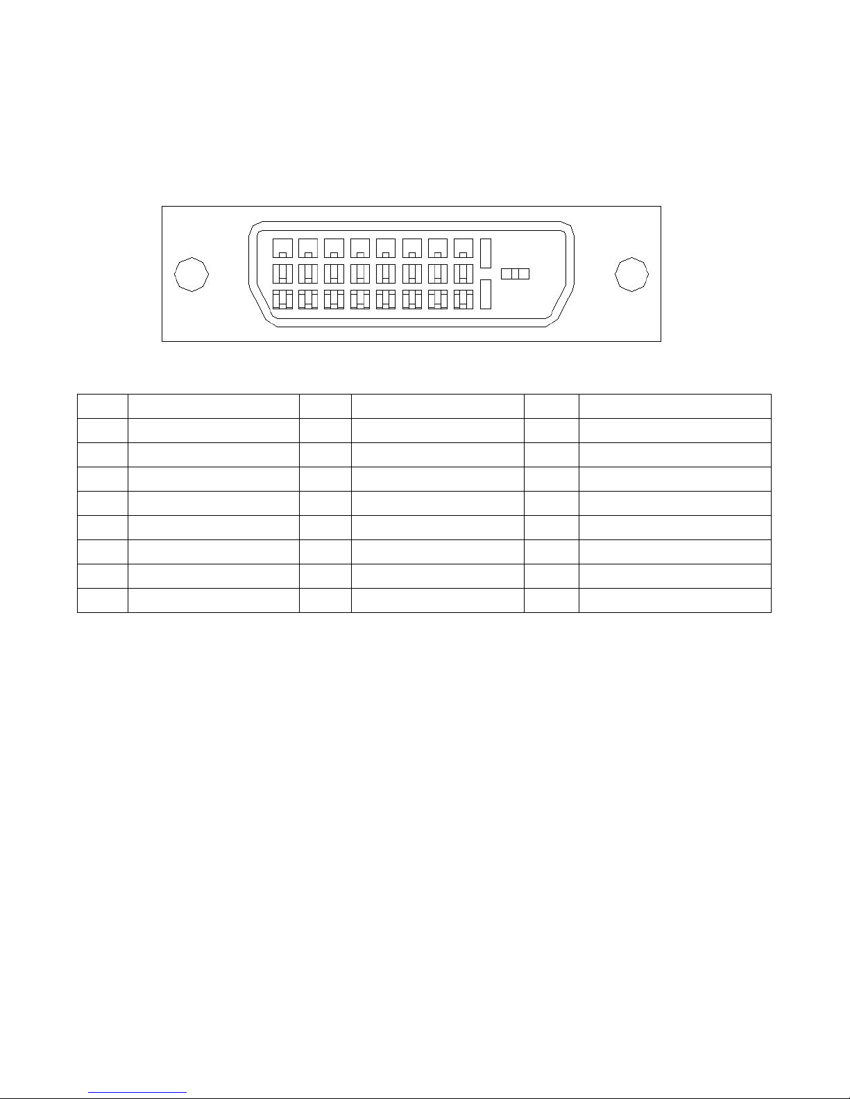
DATA INPUT:Digital and analog video signal input connector
(a)DVI:24pin digital only connector
Digital data input connector (VESA DFP)
Signal Pin Assignments:
Pin Signal Assignment Pin Signal Assignment Pin Signal Assignment
1 T.M.D.S. Data 2- 9 T.M.D.S. Data 1- 17 T.M.D.S. Data 0-
2 T.M.D.S. Data 2+ 10 T.M.D.S. Data 1+ 18 T.M.D.S. Data 0+
3 T.M.D.S. Data 2/4 Shield 11 T.M.D.S. Data 1/3 Shield 19 T.M.D.S. Data 0/5 Shield
4 T.M.D.S. Data 4- 12 T.M.D.S. Data 3- 20 T.M.D.S. Data 5-
5 T.M.D.S. Data 4+ 13 T.M.D.S. Data 3+ 21 T.M.D.S. Data 5+
6 DDC Clock 14 +5V Power 22 T.M.D.S. Clock Shield
7 DDC Data 15 Ground (for +5V) 23 T.M.D.S. Clock +
8 No Connect 16 Hot Plug Detect 24 T.M.D.S. Clock -
Audio:R input (Right channel of stereo sound ; red color of RCA JACK)
L input (Left channel of stereo sound ; white color of RCA JACK)
Page20 of 79
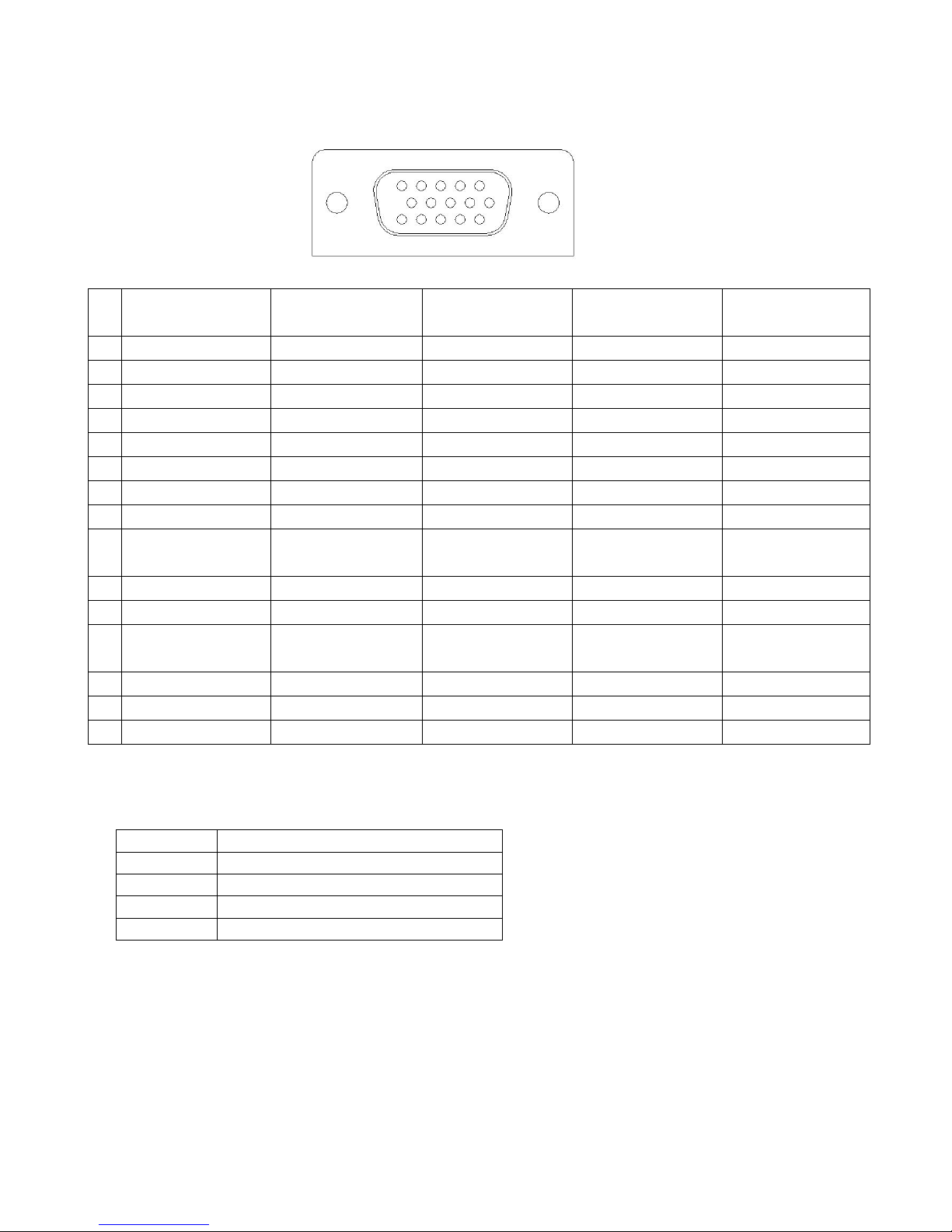
(b)VGA:15 pin D-sub analog video signal input connector
15 pin D-type connector Pin Assignments:
Pin Standard VGA DDC1 Host DDC2B Host
DDC2B+ or
DDC2AB Host
DDC1/2 Display
1 Red Video Red Video Red Video Red Video Red Video
2 Green Video Green Video Green Video Green Video Green Video
3 Blue Video Blue Video Blue Video Blue Video Blue Video
4 Monitor ID bit 2 Monitor ID bit 2 Monitor ID bit 2 Monitor ID bit 2 Monitor ID bit 2
5 Test (ground) Return Return Return Return
6 Red video return Red video return Red video return Red video return Red video return
7 Green video return Green video return Green video return Green video return Green video return
8 Blue video return Blue video return Blue video return Blue video return Blue video return
9 No connection
(mechanical key)
+5V supply
(mandatory supply)
+5V supply
(mandatory supply)
+5V supply
(mandatory supply)
+5V load
(optional use)
10 Sync. Return Sync. Return Sync. Return Sync. Return Optional
11 Monitor ID bit 0 Monitor ID bit 0 Monitor ID bit 0 Monitor ID bit 0 Monitor ID bit 0
12 Monitor ID bit 1 Data from display Bi-directional data
(SDA)
Bi-directional data
(SDA)
Bi-directional data
(SDA)
13 Horizontal sync. Horizontal sync. Horizontal sync. Horizontal sync. Horizontal sync.
14 Vertical sync. Vertical sync. Vertical sync. Vertical sync. Vertical sync.
15 Monitor ID bit 3 Open Data clock (SCL) Data clock (SCL) Data clock (SCL)
Audio:3.5 mm stereo mini jack*1
DDC Level requirement.
DDC Level Required Current Capability
DDC1 Minimum of 50mA, maximum of 1 A
DDC2B Minimum of 50mA, maximum of 1 A
DDC2B+ Minimum of 50mA, maximum of 1 A
DDC2ab Minimum of 300mA, maximum of 1 A
Page21 of 79
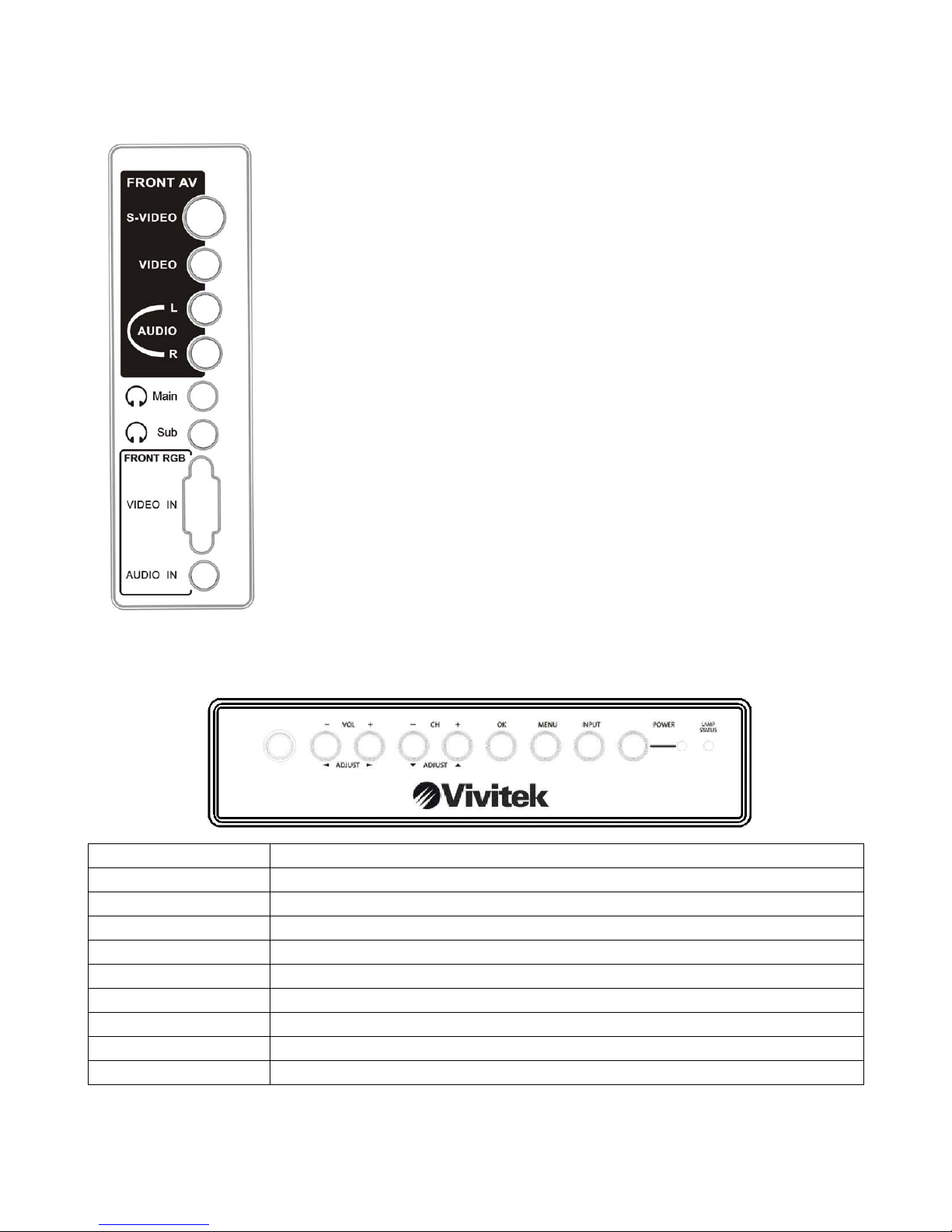
4.3.2. Hardware function(SIDE):
AV IN:Audio and video input connector(1 set)
(a)AUDIO:R input (Right channel of stereo sound ; red color of
RCA JACK)
L input (Left channel of stereo sound ; white color of
RCA JACK)
(b)VIDEO:Composite video signal input (yellow color of RCA
JACK)
(c)S-VIDEO:Y/C separation signal input (4 pin Mini-DIN)
AUDIO OUT:Phone output x2 (Sound output connector to Earphone ; green
color)
VGA:(a)15 pin D-sub analog video signal input connector
(b)Audio:3.5mm stereo mini jack x 1, green color
4.3.3. Control keypad
Name Usage
Power LED Power On:BLUE Stand-by:Orange Power Off:Not lit
Up OSD Menu Item Choice or Adjust (┼)
Down OSD Menu Item Choice or Adjust (─)
Volume Up Volume Adjust (┼)
Volume Down Volume Adjust (─)
Menu OSD Menu Open/Close or Exit Edit mode
Enter OSD Menu Item Enter or Entry Edit mode
INPUT Switches input source
Lamp LED Warm-up / cool-down:Flashing
Page22 of 79
 Loading...