

Page 1
Installation Manual
Model:LT30B-G
It is imperative that the installation instructions within this manual are followed for ●
safety reasons. Vivitek Corporation is not responsible for damages resulting from
incorrectly installed mounts or projectors on to the mount.
Sufcient expertise is required for installing this projector wall mount.●
Do not use the projector wall mount for purposes other than for which it is designed.●
Please contact Vivitek at 1-855-885-2378 with any questions pertaining to the correct ●
installation of this projector mount.
46101 FREMONT BLVD, FREMONT, CA. 94538 - TEL 855.885.2378 - EMAIL: - WWW.VIVITEKUSA.COMPROAV@VIVITEKCORP.COM
Page 2
Important Safety
2
3
4
5
7
8
9
*
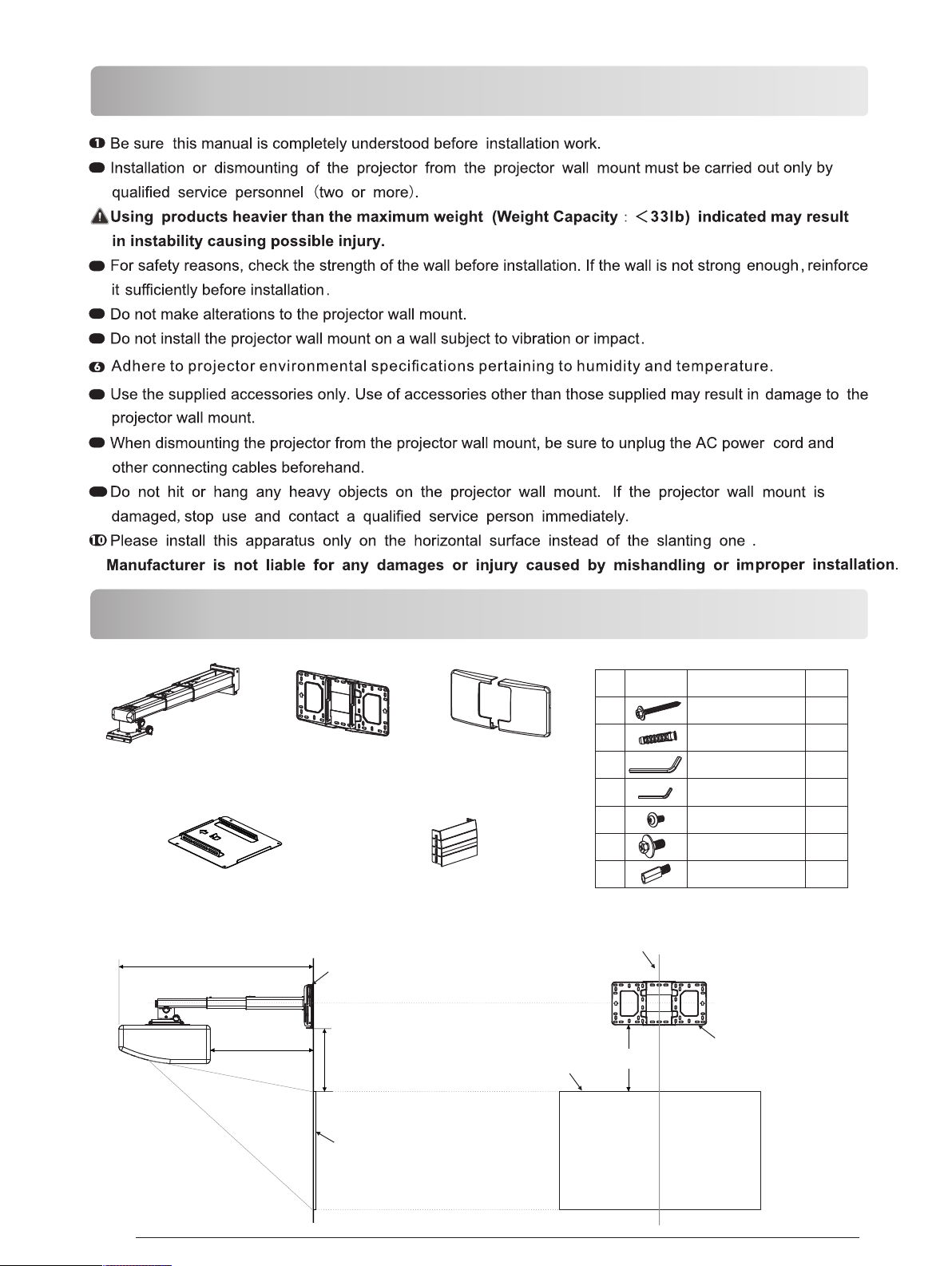
Checking The Supplied Accessories
Fixed Support Arm X 1
Projector Mounting
L2
Wall Plate X 1
Plate X 1
Wall Cover X 1
Wall Plate Cover X 1
Wal l plate
diagrammatic
NO
presentation
A
B
C
D
E
F
G
Wal l plate mus t be alig ned to cent er of screen
designation
Screw(M6X55)
Φ10mm Anchor bolt
L5 Allen key
L3 Allen key
Screw(M4X8)
Screw(M6X15)
M4 connecting
screw
quantity
5
5
1
1
4
4
4
Pg.2
L1
V-Offs et
Project ion screen
Top of image
V-Offs et
Project ion screen
Bottom of
mountin g plate
Page 3
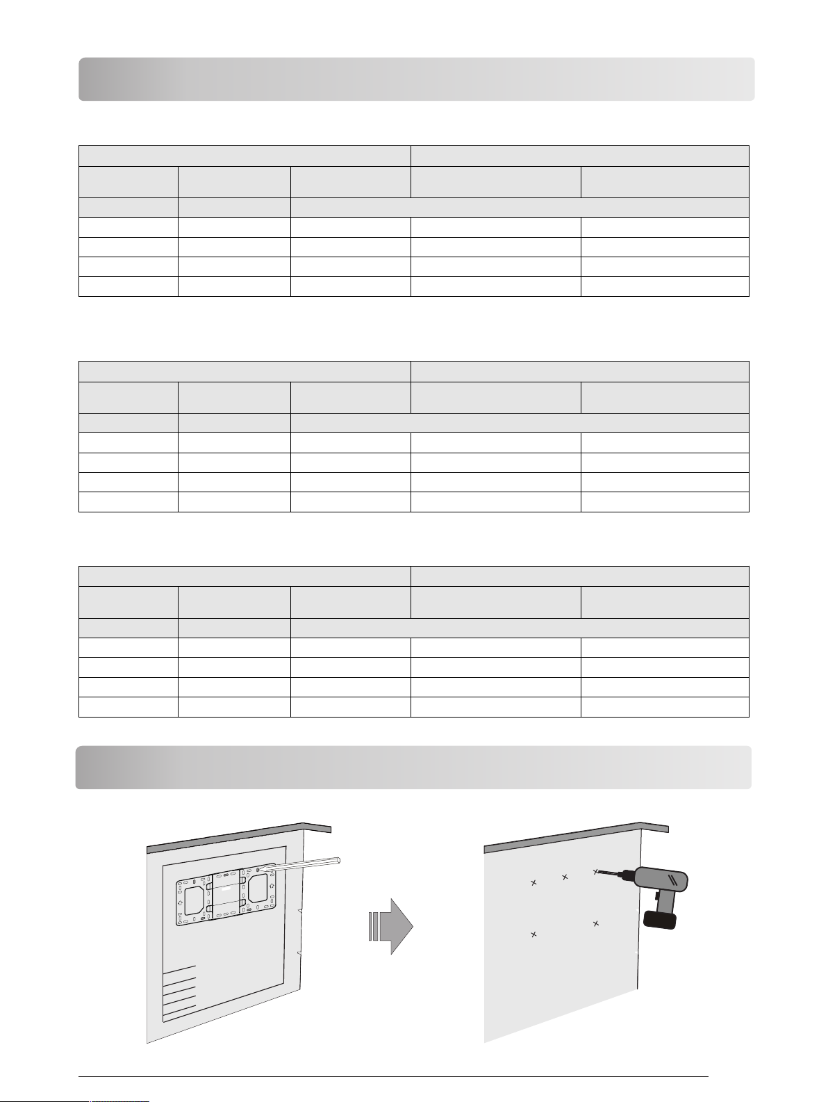
Checking The Installation Position
1080P [1920 x 1080]
Proje ction i mage si ze Insta llati on dist ance
Diago nal Width x H eight
inch
80
105
125
150
cm x cm
177 x 99. 6
232 x 130
277 x 156
332 x 187
WXGA [1280 x 800]
Proje ction i mage si ze Insta llati on dist ance
Diago nal Width x H eight
inch
80
105
125
150
cm x cm
172 x 108
226 x 141
269 x 168
323x 202
Botto m heigh t
(V-Off set)
11.1(2 8.2)
13.4( 34)
15.23 (38.7 )
17.53 (44.5 )
Botto m heigh t
(V-Off set)
101.0 5(256 .7)
120.9 (307. 1)
136.7 8(347 .4)
156.6 2(397 .8)
From a pr oject ing sur face
to the re ar of the u nit L1
From a pr oject ing sur face
to the re ar of the u nit L1
inch (c m)
1.63( 4.1)
6.87( 17.5)
11.06( 28.1)
16.3( 41.4)
inch (c m)
20.15 (51.2 )
73.67 (187. 1)
116.49 (295. 9)
169.9 9(431 .8)
From a pr oject ing sur face
to the re ar of the u nit L2
16.98 (43.1 )
22.22 (56.5 )
26.42 (67.1 )
31.65 (80.4 )
From a pr oject ing sur face
to the re ar of the u nit L2
173.6 9(441 .2)
227.2 2(577 .1)
270.0 3(685 .9)
323.5 3(821 .8)
XGA [1024x768]
Proje ction i mage si ze Insta llati on dist ance
Diago nal Width x H eight
inch
65
80
105
125
cm x cm
132 x 99
163 x 120
213 x 160
254x 191
Botto m heigh t
(V-Off set)
106.4 9(270 .5)
122.4 (310. 9)
148.9 (378. 2)
170.1 (432. 1)
From a pr oject ing sur face
to the re ar of the u nit L1
inch (c m)
13.02 (33.1 )
50.88 (129. 2)
113.95 (289. 4)
161.4 1(417 .6)
To Set The Projector Wall Mount On The Wall
From a pr oject ing sur face
to the re ar of the u nit L2
166.5 7(423 .1)
204.4 2(519 .2)
267.5 0(679 .4)
317.9 5(807 .6)
108 0P(1 920 x108 0)
Pg.3
Page 4

● The bracket is suitable for concrete wall mounting or wooden stud wall.
● Concrete wall mounting thickness must be a minimum 4'' (100mm). Anchor bolt and screw (M6 × 55) are
needed to be used for concrete wall installation.
● Dry-wall wall thickness must be a minimum 4.5" (114mm). Only screw(M6 × 55) is needed to be used for
installation, and gypsum board thickness less than 0.59" (15mm).
>55mm
If the wall is not strong enough, reinforce it sufficiently before installation.
● Please contact reseller if you have any questions
ø10~11mm
B
about mounting surface issue.
Take off the cap
The arrows up
Loosen the screw
Concrete wall mounting
>55mm
ø3mm
Dry-wall mounting
When installation on the
wood stud wall, Al ign t he
center of the wall mou nt
plate with the center of
A
the stud.
C
screw central point
The arrows up
Use anchor bolt
Not use anchor bolt
A
C
screw (M6 × 55) are needed
for installation in concrete wall mounting
D
The cables
Loosen the screws with L3 allen wrench,
pull out the support arm around 4'' (100mm)
and make power cable & signal cables go
through the support arm.
Pg.4
The cables
screw (M6 × 55) are needed
for installation in dry-wall mounting
F
C
The cables
The cables can be got through the wall plate
by three ways as shown in the pictures. The n,
Lock the screw “F” , but not tighten it.
Page 5

● You can adjust the projector upward/
-downward according to your need.
● Tighten the screw “F” after locating
the projector position.
Sliding d istance of
adjusti ng the projector
upward/ downward:
3.15''( 80mm)
To Install The Projector On The Projector Wall Mount
If the surf ace is not at,
pls use the “ G” to avoid
interfe rence.
F
C
E
G
● Move the projector mounting plate leftwards/rightwards to determine the projector position.
Leftward/Rightward
sliding distance
A
A
B
B
A
Screen Adjustment Direction
B
Pg.5
Page 6

To Install The Projector On The Projector Wall Mount
13in
12in
320mm
360mm
14in
420mm
16in
17in
Power cab le
and signa l cable
Tighten the screws
Connect power cable and other signal
cable to projector
To Adjust The Projector Forwards/Backwards
D
A
420mm
17in
B
230mm
9in
200mm
8in
390mm
16in
360mm
15in
14in
320mm
13in
290mm
12in
260mm
11in
10in
Check the scaleplate
to see the distance from
mounting plate to the wall.
Note: To make adjustments to meet your demands, screws must be loosened in a specific
order. (When the length of the inside arm does not meet your requirements, then you should
loosen the screws on the outside arm to adjust the middle arm. Under this circumstance, the
number read on the middle arm is correct).
A
A
B
B
Screen Adjustment Direction
Pg.6
Page 7

To Adjust The Projector Upwards/Downwards
F
C
To Adjust The Vertical Tilt Knob
A
B
A
B
A
B
Screen Adjustment Direction
A
Screen
Adjustment
Direction
Adjustment Knob
To Adjust The Horizontal Roll Knob
A
Adjustment Knob
B
A
Screen Adjustment Direction
B
B
Pg.7
Page 8

To Adjust The Horizontal Rotation Knob
A
B
A
Adjustment Knob
Screen Adjustment Direction
To Place The Decorative Cover Knob
Wall Plate cover
1
2
or
1
2
3
4
1
2
3
1
B
Note: When all adjustments are completed, the wall plate covers can be used to cover the
blank area on the top of wall plate. The number of wall plate covers used depends on the
size of the blank area. But the wall cover must be used in an specific order as the picture
on the left shows. Finally, put the wall cover on.
Product Information:
Model
Product Weight 9.9 lbs (4.5kg)
Load Capacity 33 lbs (15kg)
Adjustable Range
Adjustable Angle ± 5° tilt, left\right, front\rear and lateral rotation adjustment
8.7" (225m m) - 19.5" (495mm)
(from mo unting plate center to the screen)
LT30B-G
 Loading...